1
/~
,-""
---=,
"',"--""'~~,~-,...=
uni
.
---
en@
MC 61 0
MARINE RADIOTELEPHONE
OWNER'S MANUAL
.
'::r:
""'"
- .-
..
'1
f-.
UNIDEN MC610,
;
The UNIDEN MC610 VHF marine radio
transceiver has been designed to give you a
rugged reliable instrument that will provide you with years of trouble-free seNice.
You are encouraged to thoroughly read
this manual to acquaint yourself with the
characteristics and operation of your transceiver so that you can contribute to the
longevity of your investment.
With proper care and maintenance, your
UNIDEN MC61 0 will outlast your present
vessel and seNe you well on board several
more. The full features and flexibility de-
signed into this quality transceiver will prevent it from becoming obsolete regardless
of changes in craft or geographic locations.
The unit may be mounted in any number of
convenient locations by utilizing the universal mounting bracket.
The UNIDEN MC610 is of all solid state design with conseNatively rated rugged components and materials compatible with the
marine environment. The transceiver utilizes a number of gaskets, sealing rings,
waterproof membranes, and other sealants to effect a splash proof housing for
protection of the electronics.
INSTALLA;TI,ON
CAUTION: The MC610 will operate only with nominal 12 volt negative ground
battery systems.
It is important to carefully determine the
most suitable location for your MC610 on
your vessel. Electrical, mechanical, and environmental considerations must all be taken into account. You must select the optimum relationship among these considerations.
2. The microphone connector faces forward allowing convenient in-dash or
"built-in" installations.
Keep in mind the flexibility designed into
the MC610 so that you can most conveniently use your radio. Features which should
be considered are:
4. The REMOTEspeaker jack may be used
with an auxiliary speaker.
3. The front panel can be fully reversed to
provide for optimum viewing and operating for any mounting position.
All connections are "plug-in" type for
easy removal of the radio.
1. Universal mounting bracket may be installed on either top or bottom of shelf,
bulkhead, or overhead mounting.
"
~
-
--- -, -
_.-
~
r-
r
-=
<:
!-.~._=---,,~~
I
ANTENNA
CONSIDERATIONS
A variety of antennas is available from a
number of quality suppliers. It is recommended you draw upon the advice of your
Marine Dealer in determining a suitable
antenna for your vessel and range requirements.
. ,
---
The general rules for antennas are: The
more gain the greater the range and, the
higher above the water line the greater the
range. Antennas should be located so as
not to be in proximity to metal objects. Antennas should not have excessively long
coaxial feed cables.
."
"
CHOOSING.A'LQCA
Some of the more important external factors to consider in selecting the location of
your MC610 are:
1. Select a location is free from spray and
splash.
2. Keep the battery leads as short as possible. Connection directly to the battery is
most desirable. Ifdirect connection cannot be made with the supplied power
lead, any extension should be made
with # 10 AWG wire. Long extensions
should use larger wire.
3. Keep the antenna lead as short as possible. Long antenna leads can cause substantial loss of performance for both receiving and transmitting.
4. Locate your antenna as high as possible
and clear from metal objects. The reliable range of coverage is a direct function of antenna height.
5. Select a location that does not allow the
radio to be subjected to direct sunlight
(including that coming through windowsJ.
'.
TION
7. Select a location well away from the
ship"s compass. Auxiliary speakers also
should be located away from the compass.
Afteryou have carefully considered thevarious factors affecting your choice of location, position the radio (with the bracket,
microphone, power plug, antenna plug
and any auxiliary plugs installedJ into the
selected location to assure, there is no interference with surrounding items. Mark
the location of the mounting bracket.
Remove the bracket from the radio and use
it as a template to mark the holes to be
drilled for the mounting hardware. Drillthe
holes and mount the bracket with hardware compatible with the material of the
mounting surface. Install the power cable
(red is +, black is-J, antenna and all other
auxiliary cables and accessories.
Install the radio into the mounting bracket
and connect all cables and accessories to
the appropriate jacks and connectors.
6. Select a location that allows free air flow
around the heat sink on the rear of the
radio.
--
1::::
'---~
,-,---
r
~
-==
~
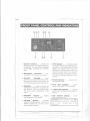
CDChannel Selector. . . Selectsthe
desired channel. LEDdisplay shows 01
through 88. All channels are displayed
by two digits, including "a" on the first
digit.
@ Microphone
Connector...
Receptacle for microphone connection.
CID
ON/OFF
VOLUME. . . Turns
power on and adjust the listening level.
Whenever the power is turned on, the
unit automatically goes to Channel 16.
.'
(j) CHI6Selector. . . Providesinstant
tuning to CHi 6 overriding RotaryChannel selector. LEDindicator and Channel
display will indicate when unit is on
Channel 16. When you press "OFF",the
channel will go back to the channel
tuned just before you pressed "CH 16".
The Channel display will go back to that
channel.
@ TXLEDIndicator.
the transmit mode.
. . Glows red in
@ SQUELCH.. . Used to silencethe
@ CHI6 LED Indicator...
Lights
when CH16 SELECTORis activated.
background noise when no signal is being received. Turn the knob just past
the point where background noise
stops.
@ I WATT LED Indicator.
. . Shows
when unit is switched to Low power (1
WATT).
CIDDIM/BRIT
the brightness
Selector...
of th~ display.
Adjusts
@ IW/25W
Selector...
Controls
transmitter output power. Use the 1W
(WATT) position for in-port or short
range communications.
,
@ LED Channel Display...
cates channel in use.
Indi-
CaUTION: When CH87A is used, LED
channel display shows as 87 , 8 (bigger
than 7) and 7 (smaller than 8) by
comparison.
.
...
~
-
;;"E
r
_. - -
-
--
--r
-=
.-- -
~
~-""
-..,
.
.
REAR PANEL CONNECTORS
3
1
CDREMOTE
Speaker
Connec-
tor. . . Ifyou want to use another
speaker in addition to the one in the unit, a four or eight ohm speaker equipped
with a miniature phone plug may be
connected to thisjack. Tooperate, connect external speaker (not supplied)
with this phone plug into jack located
on back of unit. Note that both speakers built-in and external can be used simultaneously.
2
@ DC Power Connector. . . Make
the battery connections with the cable
supplied. Remember, red is +, black is
-. The power cord is equipped with a
fuse to protect the radio. Use only a 6A
fast blow fuse for replacement. Thisfuse
issupplied with the unit as an accessory.
@ANT Connector. . . Connect the
antenna here. A type PL259 connector
is required to make proper connection.
.'
-
-...
~
1
_.
--
-
r
---
--
1--
=
.
=
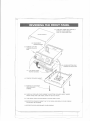
REVERSING/.THEFRONTPANEl
(2) TURN UNIT OVER AND CAREFULLY
REMOVE COVER CABINET
PULL UP FROM REAR FIRST.
(5) REMOVETOP TWO
SCREWSON EACH
SIDE.
(6) LOOSENBOTTOM TWO
SCREWSON EACH SIDE.
(7) FLIP FRONT PANEL.
TIGHTEN SCREWS.
(4) REMOVESPEAKERCABINET.
,
,
'
f.
------
(1) REMOVE FOUR SCREWS
FROM
SPEAKER
CABINET.
l
(8) CAREFULLYREPLACECOVERCABINETON BOTTOM OF RADIO. INSERTUNDER
FRONTPANELFIRSTAND THEN LOWERAT REAROF RADIO.
(9) TURN RADIOOVERAND RECONNECTSPEAKERWIRE LEADS.
(10)REPOSITIONSPEAKERCABINETON TOP OF RADIOAND REPLACEFOUR SCREWS
TO SECURETHE HOUSING.
(11) RETIGHTEN FOUR APPEARANCE COVER SCREWS.
r
'q:::
--
..-_. - '.
--
-----
1
,
.
CHANNELS AND FUNCTIONS
VHF FM MARINE RADIOTELEPHONE
FREOUENCY(MHz'
CHANNEL
DESIGN
01
02
03
04
05
06
07
OB
09
10
JJ
12
13
14
15
16
17
IB
19
20
21
22
23
24
25
26
27
2B
60
61
62
63
64
65
66
67
6B
69
71
72
73
74
77
7B
79
BO
BI
B2
B3
B4
85
86
87
87A
88
SHIP
SHORE
156.050
156.100
156.150
156.200
156.250
156.300
156.350
I56.400
J56.450
156.500
156.550
156.600
156.650
156.700
156.750
156.BOO
156.B50
I56.900
156.950
157.000
157.050
157.100
157.150
157.200
157.250
157.300
157.350
157.400
156.025
156.075
156.125
156.175
156.225
156.275
156.325
156.375
156.425
156.475
156.575
156.625
156.675
156.725
156.B75
156.925
156.975
157.025
157.075
157.125
157.175
157.225
157.275
157.325
157.375
157.375
157.425
160.650
160.700
160.750
160.BOO
160.B50
156.300
160.950
156.400
156.450
156.500
156.550
156.600
156.650
156.700
156.750
I 56.BOO
156.B50
161.500
161.550
161.600
161.650
161.700
161.750
16I.BOO
16I.B50
161.900
161.950
162.000
160.625
160.675
160.725
160.775
I60.B25
160.B75
160.925
156.375
156.425
156.475
156.575
156.625
156.675
156.725
156.B75
161.525
161.575
161.625
161.675
161.725
161.775
161.B25
161.875
161.925
161.975
157.375
162.025
TYPE
TRAFFIC
(INTERNATIONAL CHANNELS)
SHIP
TO SHIP
SHIP
TO SHORE
YTS
Port Ops
Port Ops
Port Ops
YTS
Safety
Com'l
Corn"
Corn" & Non Com'I
Corn"
Corn"
Port Ops
Navigational
Port Ops
Environmental
SafetyCalling
State Control
Corn"
Com'l
Port Ops
Coast Guard
Coast Guard
Coast Guard
Public Corresp.
Public Corresp.
PublicCorresp.
PublicCorresp.
Public Corresp.
Yes
Yes
Yes
Yes
Yes
Yes
Yes
Yes
Yes
Yes
Yes
Yes
Yes
Yes
Yes
Yes
Yes
Yes
Yes
Yes
Yes
Yes
Yes
No
No
No
No
No
Yes
Yes
Yes
Yes
Yes
No
Yes
No
Yes
Yes
Yes
Yes
Yes
Yes
Yes
Yes
Yes
Yes
Yes
Yes
Yes
Yes
Yes
Yes
Yes
Yes
Yes
Yes
Port Ops
Port Ops
Corn"
Non Com'l
Non Corn"
Non Corn"
Non Corn"
Port Ops
Port Ops
Port Ops
Non Corn"
Com'l
Com'l
Coast Guard
USGov On'y
Coast Guard
Public Corresp.
Public Corresp.
Public Corresp.
Public Corresp.
Yes
Yes
Yes
Yes
Yes
Yes
Yes
Yes
Yes
Yes
Yes
Yes
Yes
Yes
Yes
Yes
No
No
No
No
Yes
Yes
No
Yes
Yes
Yes
No
Yes
Yes
No
Yes
Yes
Yes
Yes
Yes
Yes
Yes
Yes
Yes
Yes
Coast Guard
Busy Tel.
Busy Tel.
Busy Tel.
Busy Tel.
Com'l
Yes
No
Busy Tel.
PERMANENT
SCAN LIST
Fish
Environmental
Busy Tel.
Busy Tel.
Busy Tel.
Busy Tel.
Busy Tel.
Fish
Fish
Fish
Fish
Coast Guard
CAUTION: OPERATION ON CHANNELS 15 AND 17 HAS BEEN ELECTRONICALLY
RESTRICTEDTO LOW POWER TO PROTECTCH. 16, THE DISTRESSFREQUENCY.
I
--"...
--
--
r
------
~
ENGINE NOISE SUPPRESSION
Interference from the impulse noise generated by the electrical systems of engines is
sometimes a prob/e.m with radios. The
MC6 10 has been designed to be essentially
impeNious to ignition impulse noise and d/ternator noise. However, in some installations it may be necessary to take measures
to further reduce the effect of noise interference. All DC battery wires, antenna
lead, and accessory cables should be routed away from the engine and engine compartment and from power cabling carrying
particularly high currents.
In severe cases of impulse noise interference, it may be necessary to install a noise
suppression kit that is available from your
Marine Dealer.
CARE AND MAINTENANCE
Your MC610 is a precision piece of electronic equipment and you should treat it
accordingly. Due to the rugged design,
very little maintenance is required, however, a few precautions should be obseNed.
If the antenna has been damaged, you
should not transmit except in case of
emergency. A defective antenna may cause
damage to your radio.
You are urged to arrange for periodic performance checks with your Marine dealer.
Ifyou radio has been accidentally subjected
to spray or splash you should immediately
wipe it down with a soft cloth dampened
with fresh water.
"
f
1::
--
---
~
-
~
~.~,.,.....
MEMO
- --,::
~
r
-l-'
<:::::;
TWO YEAR LIMITED WARRANTY
WARRANTOR. SANTRONICAGENCIES
PTY.LTD. 13 Garema Circuit, Kingsgrove
NSW 2208 ("SANTRONIC"J.
ELEMENTS OF WARRANTY. SANTRONIC warrants, for the duration of this
warranty, its UNIDEN Product to be
free from defects in materials and craftsmanship with only the limitation or exclusions set out below.
WARRANTY DURATION. ThisWarranty
shall terminate and be of no further effect
Two (2Jyears after the date of original purchase of the Product or at the time the Products is (aJ damaged or not maintained as
reasonable and necessary, (bJ modified, (cJ
improperly installed, (dJ is repaired by
someone other Warrantor for a defect or
malfunction covered by this Warranty, or
(eJ used in a manner or purpose for which
the Product was not intended.
PARTS COVERED. This Warranty covers
all components of the Products.
STATEMENTOF REMEDY. In the event
that the Product does not conform to this
Warranty at any time while this Warranty is
effective, Warrantor will repair the defect
and return it to you prepaid, without
charge for parts, seNice, or any other costs
incurred
by Warrantor or its representatives in connection with the performance of this Warranty. In addition, if the Product contains a
defect or malfunction which is not repaired
after a reasonable number of attempts by
Warrantor to repair the Product, the Product or defective component will at our discretion, be replaced without charge, when
the defective product is delivered to the
warrantor at 13 Garema Circuit Kingsgrove
NSW2208 free and clear of all liens and encumbrances. Please note that while the
Product will be remedied under this Warranty without charge, THIS WARRANTY
DOESNOT COVEROR PROVIDEFOR THE
REIMBURSEMENTOR PAYMENTOF INCIDENTAL OR CONSEQUENTIAL DAMAGES.
PROCEDURE FOR OBTAINING PERFORMANCE OF WARRANTY. In the
event that the Product does not conform to
this Warranty, the Product should be
shipped prepaid to Warrantor at 13 Garema Circuits Kingsgrove NSW 2208. THE
ORIGINAL OR COpy OF THE SALESRECEIPT OR OTHER VALIDEVIDENCE.OF
THEDATEOF THEORIGINALPURCHASE
MUSTACCOMPANYTHISPRODUCT.
~
AGENCIESPTY.LTD.
13 GAREMACIRCUIT,K/NGSGROVE MELBOURNE:446-448 BELLST.,
PHONE 758 1522, TELEXAA73170
EASTPRESTONVIC 3072
P.O. Box 12, Kingsgrove, NSW 2208
PHONE: (03J 484 0373
BRISBANE:3/12 RANDALLST
SLACKSCREEK,QLD 4127
PHONE 07 290 1188
Printed in Taiwan
UTSNO 183 1CA(SKJ
~~-
--
PERTH: 23 GEODES ST.,
BALCATTA WA 6021
PHONE: (09J 344 3937
.. ..
----
~