1
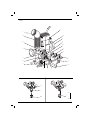
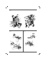
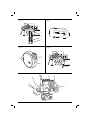
DW621
DW622
English (original instructions)
4
Copyright DEWALT
B
Figure 1
s
r
q
ff
a
p
b
xxxx
x
xx x
d
o
t
g
c
n
e
m
f
l
h
k
Figure 2
j
i
Figure 3
b
c
dd
c
u
1
Figure 4
l
q
m
x
v
p
p
o
n
m
l
w
Figure 6
Figure 5
r
o
y
t
d
e
t
d
h
j
i
g
h
f
g
2
Figure 7
Figure 8
j
z
aa
Figure 9
Figure 10
bb
a
j
cc
ee
Figure 11
o
o
3
ENGLISH
ROUTER
DW621, DW622
Congratulations!
You have chosen a DEWALT tool. Years of experience, thorough product development and innovation make
DEWALT one of the most reliable partners for professional power tool users.
Technical Data
Voltage
UK & Ireland
Type
Power Input
Power output
No-load speed
Router carriage
Router carriage stroke
Revolver depth stop
Collet size
Cutters diameter, max.
Weight
V
V
W
W
min-1
# columns
mm
mm
kg
DW621
XE
220–240
–
3
1,400
620
DW621
DW622
GB, LX, QS
GB, LX, QS
220–240
220–240
230/115
230/115
3
3
1,100
1,400
620
620
8,000–24,000 infinitely variable
2
2
2
55
55
55
3-step, with graduation and fine adjustment
1/4", 1/2"
8 mm (QS)
12 mm (QS)
1/4" (GB, LX)
1/2" (GB, LX)
36
36
36
3.1
3.1
3.1
Noise values and vibration values (triax vector sum) according to EN 60745-2-17.
LPA (emission sound pressure level)
dB(A)
86
LWA (sound power level)
dB(A)
95
KWA (uncertainty for the given sound level) dB(A)
3
86
95
3
86
95
3
Vibration emission value ah =
Uncertainty K =
3.3
1.5
3.3
1.5
m/s²
m/s²
3.3
1.5
The vibration emission level given in this information
sheet has been measured in accordance with a
standardised test given in EN 60745 and may be
used to compare one tool with another. It may be
used for a preliminary assessment of exposure.
WARNING: The declared vibration
emission level represents the main
applications of the tool. However if the
tool is used for different applications,
with different accessories or poorly
maintained, the vibration emission may
differ. This may significantly increase the
exposure level over the total working
period.
4
An estimation of the level of exposure to
vibration should also take into account
the times when the tool is switched off
or when it is running but not actually
doing the job. This may significantly
reduce the exposure level over the total
working period.
Identify additional safety measures to
protect the operator from the effects of
vibration such as: maintain the tool and
the accessories, keep the hands warm,
organisation of work patterns.
Fuses:
Europe
U.K. & Ireland
230 V tools
230 V tools
10 Amperes, mains
13 Amperes, in plugs
ENGLISH
Definitions: Safety Guidelines
The definitions below describe the level of severity
for each signal word. Please read the manual and
pay attention to these symbols.
DANGER: Indicates an imminently
hazardous situation which, if not avoided,
will result in death or serious injury.
WARNING: Indicates a potentially
hazardous situation which, if not
avoided, could result in death or
serious injury.
CAUTION: Indicates a potentially
hazardous situation which, if not
avoided, may result in minor or
moderate injury.
NOTICE: Indicates a practice not
related to personal injury which, if
not avoided, may result in property
damage.
Denotes risk of electric shock.
Denotes risk of fire.
EC-Declaration of Conformity
MACHINERY DIRECTIVE
ROUTER
DW621, DW622
DEWALT declares that these products described
under Technical Data are in compliance with:
2006/42/EC, EN 60745-1, EN 60745-2-17.
These products also comply with Directive
2014/30/EU and 2011/65/EU. For more information,
please contact DEWALT at the following address or
refer to the back of the manual.
The undersigned is responsible for compilation of
the technical file and makes this declaration on
behalf of DEWALT.
Horst Grossmann
Vice President Engineering
DEWALT, Richard-Klinger-Straße 11,
D-65510, Idstein, Germany
06.03.2015
WARNING: To reduce the risk of injury,
read the instruction manual.
General Power Tool Safety Warnings
WARNING! Read all safety warnings
and instructions Failure to follow the
warnings and instructions may result in
electric shock, fire and/or serious injury.
SAVE ALL WARNINGS AND INSTRUCTIONS
FOR FUTURE REFERENCE
The term “power tool” in the warnings refers
to your mains-operated (corded) power tool or
battery-operated (cordless) power tool.
1) WORK AREA SAFETY
a) Keep work area clean and well lit.
Cluttered or dark areas invite accidents.
b) Do not operate power tools in explosive
atmospheres, such as in the presence of
flammable liquids, gases or dust. Power
tools create sparks which may ignite the dust
or fumes.
c) Keep children and bystanders away while
operating a power tool. Distractions can
cause you to lose control.
2) ELECTRICAL SAFETY
a) Power tool plugs must match the outlet.
Never modify the plug in any way. Do
not use any adapter plugs with earthed
(grounded) power tools. Unmodified plugs
and matching outlets will reduce risk of
electric shock.
b) Avoid body contact with earthed or
grounded surfaces such as pipes,
radiators, ranges and refrigerators. There
is an increased risk of electric shock if your
body is earthed or grounded.
c) Do not expose power tools to rain or wet
conditions. Water entering a power tool will
increase the risk of electric shock.
d) Do not abuse the cord. Never use the
cord for carrying, pulling or unplugging
the power tool. Keep cord away from
heat, oil, sharp edges or moving parts.
Damaged or entangled cords increase the
risk of electric shock.
e) When operating a power tool outdoors,
use an extension cord suitable for outdoor
use. Use of a cord suitable for outdoor use
reduces the risk of electric shock.
f) If operating a power tool in a damp
location is unavoidable, use a residual
current device (RCD) protected supply.
Use of an RCD reduces the risk of electric
shock.
5
ENGLISH
3) PERSONAL SAFETY
a) Stay alert, watch what you are doing and
use common sense when operating a
power tool. Do not use a power tool while
you are tired or under the influence of
drugs, alcohol or medication. A moment of
inattention while operating power tools may
result in serious personal injury.
b) Use personal protective equipment.
Always wear eye protection. Protective
equipment such as dust mask, non-skid
safety shoes, hard hat, or hearing protection
used for appropriate conditions will reduce
personal injuries.
c) Prevent unintentional starting. Ensure
the switch is in the off position before
connecting to power source and/or
battery pack, picking up or carrying the
tool. Carrying power tools with your finger
on the switch or energising power tools that
have the switch on invites accidents.
d) Remove any adjusting key or wrench
before turning the power tool on. A
wrench or a key left attached to a rotating
part of the power tool may result in personal
injury.
e) Do not overreach. Keep proper
footing and balance at all times. This
enables better control of the power tool in
unexpected situations.
f) Dress properly. Do not wear loose
clothing or jewellery. Keep your hair,
clothing and gloves away from moving
parts. Loose clothes, jewellery or long hair
can be caught in moving parts.
g) If devices are provided for the connection
of dust extraction and collection facilities,
ensure these are connected and properly
used. Use of dust collection can reduce
dust-related hazards.
4) POWER TOOL USE AND CARE
a) Do not force the power tool. Use the
correct power tool for your application.
The correct power tool will do the job
better and safer at the rate for which it
was designed.
b) Do not use the power tool if the switch
does not turn it on and off. Any power
tool that cannot be controlled with the switch
is dangerous and must be repaired.
c) Disconnect the plug from the power
source and/or the battery pack from
the power tool before making any
adjustments, changing accessories, or
storing power tools. Such preventive safety
measures reduce the risk of starting the
power tool accidentally.
6
d)
e)
f)
g)
Store idle power tools out of the reach
of children and do not allow persons
unfamiliar with the power tool or these
instructions to operate the power tool.
Power tools are dangerous in the hands of
untrained users.
Maintain power tools. Check for
misalignment or binding of moving parts,
breakage of parts and any other condition
that may affect the power tool’s operation.
If damaged, have the power tool repaired
before use. Many accidents are caused by
poorly maintained power tools.
Keep cutting tools sharp and clean.
Properly maintained cutting tools with sharp
cutting edges are less likely to bind and are
easier to control.
Use the power tool, accessories and
tool bits etc., in accordance with these
instructions taking into account the
working conditions and the work to
be performed. Use of the power tool for
operations different from those intended
could result in a hazardous situation.
5) SERVICE
a) Have your power tool serviced by a
qualified repair person using only identical
replacement parts. This will ensure that the
safety of the power tool is maintained.
Additional Safety Rules for Routers
• Hold power tool by insulated gripping
surfaces, because the cutter may contact
its own cord. Cutting a “live” wire may make
exposed metal parts of the power tool “live” and
shock the operator.
• Use clamps or another practical way to
secure and support the workpiece to a
stable platform. Holding the work by your
hand or against the body leaves it unstable and
may lead to loss of control.
Additional Safety Rules for Cutters
• Always use straight-cutters, rabbet-cutters,
profile cutters, slotter cutters or grooved knives
with a shank diameter of 6–8 mm which
corresponds to the size of the collet in your tool.
• Always use cutters suitable for a speed of min.
30,000 min-1 and marked accordingly.
WARNING: Never use cutters with
a diameter exceeding the maximum
diameter indicated in the technical data.
• For straight-cutters, rabbet-cutters,
profile cutters, the maximum shank
diameter MUST be 8 mm, the
ENGLISH
maximum diameter MUST be
36 mm, the maximum cutting
depth MUST be 10 mm.
• For slotter cutters, the maximum
shank diameter MUST be 8 mm
and the maximum diameter MUST
be 25 mm.
• For grooved knives, the maximum
shank diameter MUST be 8 mm, the
maximum diameter MUST be
40 mm and the maximum cutting
width MUST be 4 mm.
WARNING: We recommend the use of
a residual current device with a residual
current rating of 30mA or less.
Residual Risks
In spite of the application of the relevant safety
regulations and the implementation of safety
devices, certain residual risks cannot be avoided.
These are:
– Impairment of hearing
– Risk of personal injury due flying particles.
– Risk of burns due to accessories becoming hot
during operation.
– Risk of personal injury due to prolonged use.
Markings on Tool
The following pictograms are shown on the tool:
Read instruction manual before use.
1 Wrench # 17 (DW621 GB, LX, QS)
1 Wrench # 22 (DW621-XE, DW622 GB, LX, QS)
1 Dust extraction plug
1 Instruction manual
• Check for damage to the tool, parts or
accessories which may have occurred during
transport.
• Take the time to thoroughly read and
understand this manual prior to operation.
Description (fig. 1)
WARNING: Never modify the power
tool or any part of it. Damage or
personal injury could result.
a. Lock-on/lock-off switch
b. Spindle lock
c. Collet nut
d. Parallel fence locking bolt
e. Guide rods for parallel fence
f. Dust extraction outlet in parallel fence
g. Fine adjuster for parallel fence
h. Parallel fence
i. Locking bolt
j. Router base
k. Finger guard
l. Revolver depth stop
m. Depth stop
n. Depth stop locking bolt
o. Plunge limiter
DATE CODE POSITION (FIG. 1)
The Date Code (ff), which also includes the year of
manufacture, is printed into the housing.
Example:
XX XX 2015
Year of Manufacture
p. Quick adjuster for depth stop
q. Fine adjuster for depth stop
r. Dust extraction adaptor
s. Speed control dial
t. End lock
INTENDED USE
Package Contents
The package contains:
1 Router
1 Parallel fence with fine adjustment and
guiderods
1 Collet 1/4" (DW621-XE, DW621 GB, LX)
1 Collet 1/2" (DW621-XE, DW622 GB, LX)
1 Collet 8 mm (DW621 QS)
Your DEWALT DW621/DW622 high-performance
routers have been designed for professional heavy
duty routing of wood, wood products and plastics.
DO NOT use under wet conditions or in presence of
flammable liquids or gases.
These routers are professional power tools.
DO NOT let children come into contact with the
tool. Supervision is required when inexperienced
operators use this tool.
1 Collet 12 mm (DW622 QS)
1 Guide bush 24 mm
7
ENGLISH
• Young children and the infirm. This appliance
is not intended for use by young children or
infirm persons without supervision.
• This product is not intended for use by persons
(including children) suffering from diminished
physical, sensory or mental abilities; lack of
experience, knowledge or skills unless they are
supervised by a person responsible for their
safety. Children should never be left alone with
this product.
Electrical Safety
The electric motor has been designed for one
voltage only. Always check that the power supply
corresponds to the voltage on the rating plate.
Your DEWALT tool is double insulated in
accordance with EN 60745; therefore no
earth wire is required.
WARNING: 115 V units have to
be operated via a fail-safe isolating
transformer with an earth screen
between the primary and secondary
winding.
If the supply cord is damaged, it must be replaced
by a specially prepared cord available through the
DEWALT service organisation.
Mains Plug Replacement
(U.K. & Ireland Only)
If a new mains plug needs to be fitted:
• Safely dispose of the old plug.
• Connect the brown lead to the live terminal in
the plug.
• Connect the blue lead to the neutral terminal.
WARNING: No connection is to be
made to the earth terminal.
Follow the fitting instructions supplied with good
quality plugs. Recommended fuse: 13 A.
Using an Extension Cable
If an extension cable is required, use an approved 3–
core extension cable suitable for the power input of
this tool (see technical data).The minimum conductor
size is 1.5 mm2; the maximum length is 30 m.
When using a cable reel, always unwind the cable
completely.
ASSEMBLY AND ADJUSTMENTS
WARNING: To reduce the risk of
injury, turn unit off and disconnect
machine from power source before
8
installing and removing accessories,
before adjusting or changing setups or when making repairs. Be sure
the trigger switch is in the OFF position.
An accidental start-up can cause injury.
Inserting and Removing a Cutter
(fig. 2)
1. Press and hold down the spindle lock (b).
2. Using the wrench supplied, loosen the collet nut
(c) a few turns and insert a cutter (dd).
3. Tighten the collet nut and release the spindle
lock.
WARNING: Never tighten the collet nut
without a cutter in the collet.
Replacing the Collet Assembly
(fig. 3)
Your router is supplied with a 1/4", 1/2", 8 mm, or
12 mm collet fitted to the tool. The collet and the
collet nut are inseparable.
1. Loosen the collet nut (c) completely.
2. Remove the collet assembly (u).
3. Fit a new assembly and tighten the collet nut
(c).
Setting the Electronic Speed
Control Dial (fig. 1)
The speed is infinitely variable from 8,000 to 24,000
min-1 using the electronic speed control dial (s) for
uniform cutting results in all types of wood, plastics
and in aluminium.
Turn the electronic speed control dial to the required
level.
Generally, use the low setting for large diameter
cutters and the high setting for small diameter
cutters. The correct setting, however, is a matter of
experience.
1 =
8,000 min-1
2 =
9,500 min-1
3 =
11,500 min-1
4 =
16,000 min-1
5 =
19,500 min-1
6 =
22,500 min-1
7 =
24,000 min-1
Adjusting the Depth of Cut (fig. 4)
Your router is equipped with a high-precision depth
adjustment system including a zero reset ring for
both the quick adjuster and the fine adjuster.
ENGLISH
QUICK ADJUSTMENT USING THE GRADUATION
WITH ZERO RESET RING
1. Loosen the depth stop locking bolt (n).
2. Unlock the plunge limiter (o) by turning it
counterclockwise.
3. Lower the router carriage until the cutter is in
contact with the workpiece.
4. Tighten the plunge limiter (o).
Fitting the Parallel Fence (fig. 1, 5)
1. Fit the guide rods (e) to the router base (j).
2. Tighten the locking bolts (i).
3. Slide the parallel fence (h) over the rods.
4. Tighten the locking bolts (d) temporarily.
5. Remove the dust extraction adaptor (r) and
close the outlet using the dust extraction plug
(y) supplied with the tool.
5. Set the quick adjuster (p) to zero using the ring
(v). The depth stop (m) must be in contact with
the revolver depth stop (l).
Adjusting the Parallel Fence (fig. 6)
6. Adjust the depth of cut using the quick adjuster
(p) and the corresponding graduation. The
adjusted depth of cut is indicated by the
arrows (w).
2. Lower the router carriage until the cutter is in
contact with the workpiece.
7. Tighten the depth stop locking bolt (n).
1. Draw a cutting line on the material.
3. Tighten the plunge limiter (o).
4. Position the router on the cutting line.
TRIPLE DEPTH ADJUSTMENT USING THE
REVOLVER DEPTH STOP
5. Slide the parallel fence (h) against the workpiece
and tighten the locking bolts (d).
The revolver depth stop (l) can be used to set three
different depths. This is particularly useful for deep
cuts, performed in steps.
6. Adjust the parallel fence (h) using the fine
adjuster (g). The outer cutting edge of the cutter
must coincide with the cutting line.
– Place a depth template between the depth
stop (m) and the revolver depth stop (l) to
adjust the exact cutting depth.
– If required, set all three screws.
FINE ADJUSTMENT
When not using a depth template, or if the depth of
cut needs readjustment, it is recommended to use
the fine adjuster (q).
7. Firmly tighten the end lock (t).
Fitting a Guide Bush (fig. 7)
Together with a template, guide bushes play a
valuable part in cutting and shaping to a pattern.
– Fit the guide bush (z) to the router base (j) using
the screws (aa) as shown.
1. Adjust the depth of cut as described above.
2. Set the fine adjuster to zero using the ring (x).
3. Rotate the fine adjuster (q) to the required
position: one turn corresponds to approximately
1 mm and 1 mark to 0.1 mm.
Depth Adjustment with Router
Connecting a Dust Extractor
(fig. 1, 5)
Connect a dust extractor hose to the dust extraction
adaptor (r) in the router carriage column or to the
dust extraction outlet in the parallel fence (f).
INSTALLED IN INVERTED POSITION (FIG. 4)
1. Remove the depth stop (m) and replace it with
the depth stop (DE6956) available as an option.
2. Connect the threaded rod of the depth stop (m)
to the revolver depth stop (l).
3. Set the depth of cut using the adjuster on the
depth stop (m).
WARNING: For installing the router in
inverted position, refer to the relevant
instruction manual on the stationary tool.
Prior to Operation
1. Check that the cutter is correctly installed in
the collet.
2. Select the optimal speed using the electronic
speed control dial.
3. Set the cutting depth.
4. Connect a dust extractor.
5. Make sure the plunge limiter is always locked
before switching on.
9
ENGLISH
OPERATION
Instructions for Use
WARNING: Always observe the safety
instructions and applicable regulations.
WARNING: To reduce the risk
of serious personal injury, turn
tool off and disconnect tool from
power source before making any
adjustments or removing/installing
attachments or accessories.
WARNING: Always move your router as
indicated in figure 8 (outer edges/inner
edges).
Proper Hand Position (fig. 11)
WARNING: To reduce the risk of
serious personal injury, ALWAYS use
proper hand position as shown.
WARNING: To reduce the risk of
serious personal injury, ALWAYS hold
securely in anticipation of a sudden
reaction.
Proper hand position requires one hand on either
plunge limiter (o).
Switching On and Off (fig. 9)
The lock-on/lock-off switch (a) is located in the
handle on the right-hand side. The router is normally
locked in the off position.
1. Switching on: press and hold down the switch
(bb) to unlock the tool and subsequently
squeeze the trigger (cc).
2. For continuous operation, press the switch
(bb) again.
3. Switching off: squeeze the trigger (cc) again.
WARNING: Loosen the plunge limiter
and allow the router carriage to regain
its rest position before switching off.
Using the Guide Bushes (fig. 7)
1. Secure the template to the workpiece using end
clamps.
2. Select and install an appropriate guide bush (z).
3. Subtract the diameter of the cutter from the
outside diameter of the guide bush and divide
by 2. This is the difference between template
and workpiece.
WARNING: If the workpiece is not thick
enough, place it on a piece of waste
wood.
10
Guiding Off a Batten
Where an edge guide cannot be used, it is also
possible to guide the router along a batten clamped
across the workpiece (with an overhang at
both ends).
Freehand Routing
Your router can also be used without any sort of
guide, e.g. for signwriting or creative work.
WARNING: Make shallow cuts only!
Use cutters with a max. diameter of
8 mm.
Routing with Pilot Cutters (fig. 2)
Where a parallel guide or guide bush are
inappropriate, it is possible to use pilot cutters (dd)
for cutting shaped edges.
Consult your dealer for further information on the
appropriate accessories.
These include collets (6–12 mm), a depth stop
for use in inverted position, finger jointing tools
for dovetail and finger jointing jigs, dowel jointing
templates, guide bushes (17–40 mm) and guide rails
in various lengths.
MAINTENANCE
Your DEWALT power tool has been designed to
operate over a long period of time with a minimum
of maintenance. Continuous satisfactory operation
depends upon proper tool care and regular cleaning.
WARNING: To reduce the risk of
injury, turn unit off and disconnect
machine from power source before
installing and removing accessories,
before adjusting or changing setups or when making repairs. Be sure
the trigger switch is in the OFF position.
An accidental start-up can cause injury.
Cleaning the Dust Extraction
Column (fig. 10)
1. Remove the dust extraction plug or adaptor.
2. Remove the four screws (ee) in the bottom of
the router base (j).
3. Clean the dust extraction column.
4. Reassemble the parts in reverse order.
Lubrication
Your power tool requires no additional lubrication.
ENGLISH
Cleaning
WARNING: Blow dirt and dust out of
the main housing with dry air as often as
dirt is seen collecting in and around the
air vents. Wear approved eye protection
and approved dust mask when
performing this procedure.
WARNING: Never use solvents or
other harsh chemicals for cleaning the
non-metallic parts of the tool. These
chemicals may weaken the materials
used in these parts. Use a cloth
dampened only with water and mild
soap. Never let any liquid get inside the
tool; never immerse any part of the tool
into a liquid.
DEWALT provides a facility for the collection and
recycling of DEWALT products once they have
reached the end of their working life. To take
advantage of this service please return your product
to any authorised repair agent who will collect them
on our behalf.
You can check the location of your nearest
authorised repair agent by contacting your local
DEWALT office at the address indicated in this
manual. Alternatively, a list of authorised DEWALT
repair agents and full details of our after-sales
service and contacts are available on the Internet at:
www.2helpU.com.
Optional Accessories
WARNING: Since accessories, other
than those offered by DEWALT, have
not been tested with this product, use
of such accessories with this tool could
be hazardous. To reduce the risk of
injury, only DEWALT, recommended
accessories should be used with this
product.
Consult your dealer for further information on the
appropriate accessories.
Protecting the Environment
Separate collection. This product must
not be disposed of with normal
household waste.
Should you find one day that your DEWALT product
needs replacement, or if it is of no further use to
you, do not dispose of it with household waste.
Make this product available for separate collection.
Separate collection of used products
and packaging allows materials to be
recycled and used again. Re-use of
recycled materials helps prevent
environmental pollution and reduces
the demand for raw materials.
Local regulations may provide for separate collection
of electrical products from the household, at
municipal waste sites or by the retailer when you
purchase a new product.
11
12
13
Belgique et
Luxembourg België
en Luxemburg
DEWALT - Belgium BVBA
Egide Walschaertsstraat 16
2800 Mechelen
Tel: NL
Tel: FR
Fax:
Danmark
DEWALT
Roskildevej 22
2620 Albertslund
Tel: 70 20 15 10
Fax: 70 22 49 10
www.dewalt.dk
[email protected]
Deutschland
DEWALT
Richard Klinger Str. 11
65510 Idstein
Tel: 06126-21-1
Fax: 06126-21-2770
www.dewalt.de
[email protected]
Ελλάς
Τηλ: 00302108981616
DEWALT (Ελλάς) Α.Ε.
EΔΡΑ-ΓΡΑΦΕΙΑ : Στράβωνος 7
Φαξ: 00302108983570
& Λ. Βουλιαγμένης, Γλυφάδα 166 74, Αθήνα
SERVICE : Ημερος Τόπος 2 (Χάνι Αδάμ) –
193 00 Ασπρόπυργος
www.dewalt.gr
[email protected]
España
DEWALT Ibérica, S.C.A.
Parc de Negocios “Mas Blau”
Edificio Muntadas, c/Bergadá, 1, Of. A6
08820 El Prat de Llobregat (Barcelona)
Tel: 934 797 400
Fax: 934 797 419
www.dewalt.es
[email protected]
France
DEWALT
5, allée des Hêtres
BP 30084, 69579 Limonest Cedex
Tel: 04 72 20 39 20
Fax: 04 72 20 39 00
www.dewalt.fr
[email protected]
Schweiz
Suisse
Svizzera
DEWALT
In der Luberzen 42
8902 Urdorf
Tel: 044 - 755 60 70
Fax: 044 - 730 70 67
www.dewalt.ch
[email protected]
Ireland
DEWALT
Calpe House Rock Hill
Black Rock, Co. Dublin
Tel: 00353-2781800
Fax: 00353-2781811
www.dewalt.ie
Italia
DEWALT
via Energypark
20871 Vimercate (MB), IT
Tel:
800-014353
39 039 9590200
Fax: 39 039 9590313
www.dewalt.it
Nederlands
Tel: 31 164 283 063
DEWALT Netherlands BV
Holtum Noordweg 35
Fax: 31 164 283 200
6121 RE BORN, Postbus 83, 6120 AB BORN
www.dewalt.nl
Norge
DEWALT
Postboks 4613, Nydalen
0405 Oslo
Tel: 45 25 13 00
Fax: 45 25 08 00
www.dewalt.no
[email protected]
Österreich
DEWALT
Werkzeug Vertriebsges m.b.H
Oberlaaerstrasse 248, A-1230 Wien
Tel: 01 - 66116 - 0
Fax: 01 - 66116 - 614
www.dewalt.at
[email protected]
Portugal
DEWALT Limited, SARL
Tel: 214 66 75 00
Centro de Escritórios de Sintra Avenida
Fax: 214 66 75 80
Almirante Gago Coutinho, 132/134, Edifício 14
2710-418 Sintra
www.dewalt.pt
[email protected]
Suomi
DEWALT
PL 47
00521 Helsinki
Puh: 010 400 4333
Faksi: 0800 411 340
www.dewalt.fi
[email protected]
Sverige
DEWALT
Box 94
431 22 Mölndal
Tel: 031 68 61 60
Fax: 031 68 60 08
www.dewalt.se
[email protected]
Türkiye
KALE Hırdavat ve Makina A.Ş.
Defterdar Mah. Savaklar Cad. No:15
Edirnekapı / Eyüp / İSTANBUL 34050
TÜRKİYE
Tel: 0212 533 52 55
Faks: 0212 533 10 05
www.dewalt.com.tr
United
Kingdom
DEWALT, 210 Bath Road;
Slough, Berks SL1 3YD
Tel: 01753-567055
Fax: 01753-572112
www.dewalt.co.uk
[email protected]
Australia
DEWALT
82 Taryn Drive, Epping
VIC 3076 Australia
Tel: Aust 1800 338 002
Tel: NZ 0800 339 258
www.dewalt.com.au
www.dewalt.co.nz
Middle East Africa
DEWALT
P.O. Box - 17164,
Jebel Ali Free Zone (South), Dubai, UAE
Tel: 971 4 812 7400
Fax: 971 4 2822765
www.dewalt.ae
[email protected]
N424267
32 15 47 37 63
32 15 47 37 64
32 15 47 37 99
www.dewalt.be
[email protected]
01/15