1
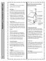
Caution Notice
CAUTION
WARNING:
RISK OF ELECTRIC SHOCK
DO NOT OPEN
TO REDUCE THE RISK OF ELECTRIC SHOCK DO NOT REMOVE COVER (OR BACK). NO USER SERVICEABLE PARTS INSIDE. REFER TO QUALIFIED PERSONNEL.
The lighting flash with arrowhead symbol, within an equilateral triangle, is intended to alert the user to the
presence of uninsulated “dangerous voltage” within the product’s enclosure that may be of sufficient magnitude
to constitute a risk of electric shock to persons.
The exclamation point within an equilateral triangle is intended to alert the user to the presence of important
operating and maintenance (servicing) insturctions in the literature accompanying the appliance.
WARNING:
TO PREVENT FIRE OR SHOCK HAZARDS, DO NOT EXPOSE THIS PRODUCT TO RAIN OR MOISTURE.
NOTE TO CABLE/TV INSTALLER:
This reminder is provided to call the CATV system installer’s attention to Article 820-40 of the National Electric Code
(U.S.A.). The code provides guidelines for proper grounding and, in particular, specifies that the cable ground shall
be connected to the grounding system of the building, as close to the point of the cable entry as practical.
REGULATORY INFORMATION
This equipment has been tested and found to comply with the limits for a Class B digital device, pursuant to Part 15
of the FCC Rules. These limits are designed to provide reasonable protection against harmful interference in a residential
installation. This equipment generates, uses and can radiate radio frequency energy and, if not installed and
used in accordance with the instructions, may cause harmful interference to radio communications. However, there
is no guarantee that interference will not occur in a particular installation. If this equipment does cause harmful interference
to radio or television reception, which can be determined by turning the equipment off and on, the user is
encouraged to try to correct the interference by one or more of the following measures:
- Reorient or relocate the receiving antenna.
- Increase the separation between the equipment and receiver.
- Connect the equipment into an outlet on a circuit different from that to which the receiver is connected.
- Consult the dealer or an experienced radio/TV technician for help.
CAUTION:
2
To comply with the limits for an FCC class B computing device, always use the signal cord and power cord supplied with this
unit. The Federal Communications Commision warns that changes or modifications to the unit not expressly approved by
the party responsible for compliance could void the user’s authority to operate the equipment.
Your product has been manufactured and tested with your safety in mind. However, improper use can result in potential
electrical shock or fire hazards. To avoid defeating the safeguards that have been built into your new product, please
read and observe the following safety points when installing and using your new product, and save them for future reference.
Observing the simple precautions discussed in this booklet can help you get many years of enjoyment and safe operation that are built into your new product. This product complies with all applicable U.S. Federal safety requirements,
and those of the Canadian Standards Association.
Important Safety Instructions
1) Read these instructions.
2) Keep these instructions.
3) Heed all warnings.
4) Follow all instructions.
5) Do not use this apparatus near water.
6) Clean only with dry cloth.
7) Do not block any ventilation openings. Install in accordance
with the manufacturer's instructions.
8) Do not install near any heat sources such as radiators, heat
registers, stoves, or other apparatus (including amplifiers) that
produce heat.
9) Do not defeat the safety purpose of the polarized or
grounding type plug. A polarized plug has two blades with one
wider than the other. A grounding type plug has two blades
and a third grounding prong. The wide blade or the third prong
are provided for your safety. If the provided plug does not fitinto your outlet, consult an electrician for replacement of the
obsolete outlet.
10) Protect the power cord from being walked on or pinched
particularly at plugs, convenience receptacles, and the point
where they exit from the apparatus.
11) Only use attachments/accessories specified by the manufacturer.
12) Use only with the cart, stand, tripod, bracket, or table specified by the manufacturer, or sold with the apparatus. When a
cart is used, use caution when moving the cart/apparatus combination to avoid injury from tipover.
13) Unplug this apparatus during lightning storms or when
unused for long periods of time.
Safety Instructions
Important safeguards for you and your new product
PORTABLE CART WARNING
14) Refer all servicing to qualified service personnel. Servicing
is required when the apparatus has been damaged in any
way,such as power-supply cord or plug is damaged, liquid has
been spilled or objects have fallen into the apparatus, the
apparatus has been exposed to rain or moisture, does not
operate normally, or has been dropped.
15) To Reduce the Risk of Fire or Electric Shock,Do not
Expose This
Apparatus To Rain or Moisture.
16) Apparatus shall not be exposed to dripping or splashing
and no objects filled with liquids, such as vases, shall be
placed on the apparatus.
3
Safety Instructions
17) Attachments
Do not use attachments not recommended by the product
manufacturer as they may cause hazards.
18) Ventilation
Slots and openings in the cabinet are provided for ventilation
and to ensure reliable operation of the product and to protect
it from overheating, and these openings must not be blocked
or covered. The openings should never be blocked by placing
the product on a bed, sofa, rug, or other similar surface.
This product should not be placed in a built-in installation
such as a bookcase or rack unless proper ventilation is provided or the manufacturer s instructions have been adheredto.
19) Power Sources
This product should be operated only from the type of power
source indicated on the marking label. If you are not sure of
the type of power supply to your home, consult your product
dealer or local power company. For products intended to operate from battery power, or other sources, refer to the operating
instructions.
20) Power-Cord Polarization
This product is equipped with a three-wire grounding type
plug, a plug having a third (grounding) pin. This plug will only
fit into the grounding-type power outlet. This is a safety feature. If you are unable to insert the plug into the outlet, contact
your electrician to replace your obsolete outlet. Do not
defeat the safety purpose of the grounding-type plug.
21) Power-Cord Protection
Power-supply cords should be routed so that they are not
likely to be walked on or pinched by items placed upon or
against them, paying particular attention to cords at plugs,
convenience receptacles, and the point where they exit from
the product.
4
Example of Grounding According to National
Electrical Code Instructions
22) Lightning
For added protection for this product (receiver) during a
lightning storm, or when it is left unattended and unused for
long periods of time, unplug it from the wall outlet and disconnect the antenna or cable system. This will prevent damage
to the product due to lightning and power-line surges.
NEC - National Electrical Code
23) Outdoor Antenna Grounding
If an outside antenna or cable system is connected to the
product, be sure the antenna or cable system is grounded so
as to provide some protection against voltage surges and
built-up static charges. Article 810 of the National Electrical
Code (U.S.A.), ANSI/ NFPA70 provides information with
regard to proper grounding of the lead-in wire to an antenna
discharge unit, size of grounding conductors, location of
antenna-dis-charge unit, connection to grounding electrodes,
and requirments for the grounding electrode.
24) Power Lines
An outside antenna system should not be located in the vicinity of overhead power lines or other electric light or power circuits, or where it can fall into such power lines or circuits.
When installing an outside antenna system,extreme care
should be taken to keep from touching such power lines or
circuits as contact with them might be fatal.
25) Overloading
Do not overload wall outlets and extension cords as this can
result in a risk of fire or electric shock.
27) Servicing
Do not attempt to service this product yourself as opening or
removing covers may expose you to dangerous voltage or
other hazards.
28) Damage Requiring Service
Unplug this product from the wall outlet and refer servicing to
qualified service personnel under the following conditions:
a. If the power-supply cord or plug is damaged.
b. If liquid has been spilled, or objects have fallen into
theproduct.
c. If the product has been exposed to rain or water.
d. If the product does not operate normally by following the
operating instructions. Adjust only those controls that are
covered by the operating instructions as an improper
adjustment of other controls may result in damage and will
often require extensive work by a qualified technician to
restore the product to its normal operation.
e. If the product has been dropped or the cabinet has been
damaged.
f. If the product exhibits a distinct change in performance.
30) Safety Check
Upon completion of any service or repairs to this product,
ask the service technician to perform safety checks to determine that the product is in proper operating condition.
31) Wall or Ceiling Mounting
The product should be mounted to a wall or ceiling only as
recommended by the manufacturer. The product may slide
or fall, causing serious injury to a child or adult, and serious
damage to the product.
32) Heat
The product should be situated away from heat sources
such as radiators, heat registers, stoves, or other products
(including amplifiers) that produce heat.
Safety Instructions
Safety Instructions
26) Object and Liquid Entry
Never push objects of any kind into this product through openings as they may touch dangerous voltage points or short-out
parts that could result in a fire or electric shock. Never spill liquid of any kind on the product.
29) Replacement Parts
When replacement parts are required, be sure the service
technician has used replacement parts specified by the
manufacturer or have the same characteristics as the original
part. Unauthorized substitutions may result in fire, electric
shock, or other hazards.
5
Contents
Caution Notice............................................................................................................................... 2
Safety Instructions.......................................................................................................................3-5
Remote Control Handset..............................................................................................................7-8
Controls............................................................................................................................................................7
Battery installation............................................................................................................................................8
Controls of
Front & Top panel.............................................................................................................................................9
Connections of
Back panel......................................................................................................................................................10
Connection to
External equipment....................................................................................................................................11-14
Menu Adjustments...................................................................................................................15-19
TV Mode........................................................................................................................................................ 15
S-Video / AV Modes....................................................................................................................................... 16
Component (YPbPr1, YPbPr2) Modes.......................................................................................................... 17
VGA Mode......................................................................................................................................................18
DVI Mode....................................................................................................................................................... 19
V-Chip............................................................................................................................................................ 20
Picture-in-Picture Menu................................................................................................................21
Description of View Modes.......................................................................................................... 22
Troubleshooting Guide.............................................................................................................23-24
Specifications...............................................................................................................................25
Limited Warranty......................................................................................................................... .26
6
2
3
5
4
6
7
8
11
12
9
10
13
14
16
18
15
17
19
21
20
22
23
23
Remote Control Handset
1
Controls
1. POWER
To turn on LCD display.
2. MUTE / OFF
Press to turn off the sound. Press again or press volume +/- to restore the
original volume.
3. DISPLAY
Press to display the current channel on screen.
4. CC
Press to activate closed caption subtitles & teletext where available.
5. FREEZE
Press to digitally freeze frame your signal source. Press again to return to live viewing.
6. SLEEP TIMER
Press repeatedly to set the sleep timer to OFF/30/60/90/120 minutes. When timer expires the LCD TV will
automatically turn off. To cancel your selection, simply press the button repeatedly until OFF is displayed
7. PIP INPUT
Press to activate Picture in Picture (PIP) whereby another input source appears in a smaller picture box.
8. MAIN
Press to activate (audio) sound from the main picture input while in PIP mode.
9. SWAP
Press to switch between the input source in the main picture and small picture box while in PIP mode.
10. PIP
Press to activate (audio) sound from the small picture box input while in PIP mode.
11. POSITION
Select the positon the small picture box displays while in PIP mode.
12. SIZE
Change the size of the small picture box while in PIP mode.
13. MENU (and Navigation)
Press to activate the OSD menu. Press again to quit the menu. Press 5634
to navigate & make selection.
14. DEL
Press to delete a favorite channel from memory.
15. FAVORITE CH
Press to scroll through custom pre-selected favorite channels.
16. MEM
Press to store a favorite channel in memory.
17. PICTURE
Press to select factory settings (Movie, Sport, Game, Vivid); User mode to select custom settings.
18. VIEW
Press to select aspect ratio preference (NORMAL, ZOOM 1, ZOOM 2, FULL).
19. VOL +/Adjust volume up or down.
20. CH (Channel) +/- (up/down)
Press to scroll through channels one at a time.
21. ENTER
22. MTS (Multi-channel TV sound)
Press MTS button and to select STEREO, MONO, or SAP (where available).
23. INPUT (Main picture signal source)
Sequentially select the signal sources as follows: TV, AV, S-VIDEO, YPbPr1, YPbPr2, VGA, and DVI
24. 0-9
Press 0-9 to select channels from 02 to 99.
25. 100/Press to select channels over 100.
26. R (Recall)
Press to select the previously viewed channel.
24
25
26
7
Battery Installation
Remote Control Handset
Your remote control handset is powered by two AAA type batteries.
1
To insert batteries, turn the remote
control over and remove the battery
cover.
2
Put the two batteries into the compartment with correct polarity.
3
Replace the cover.
To avoid damage from possible battery leakage, remove the batteries if you do not plan to use the remote control handset for an extended
period of time. Do not mix batteries of different age and type. Always discard of used batteries safely.
8
3. Channel/Function 56
Press the 56 button to select the channel in TV mode,
or to navigate in MENU mode.
Controls of
2. MENU
Activate the menu.
Press the MENU button on the top left of the LCD TV to
adjust your settings.
Front & Top Panel
1. MAIN POWER
Turn on/off LCD TV.
Press the power button in the lower right corner of the
television to turn on/off LCD TV.
When power is on, the LED indicator turns green, then
the screen image will appear in a few seconds. When
power is off, the LED indicator turns red.
4. Volume/Adjust 34
Press 34 button to adjust volume. These buttons are
also used to adjust settings in the MENU mode.
5. Input Select
After connecting your DVD, VCR, etc., select the input to
view by pressing this button repeatedly to choose
between the following input sources.
TV (NTSC TUNER)
AV
S-VIDEO
YPbPr l
YPbPr 2
VGA
DVI
Note:
1. Do not press or touch the LCD display with fingers or
other objects as this may produce temporary and in some
cases permanent abnormalities on the screen.
Channel
/ Function
Volume
/ Adjust
2. If the LCD TV is brought indoors from a cold environment, you may experience a small “flicker” when the LCD
TV is switched on. This is normal, there is nothing wrong
with the television.
9
Back Panel
Connections of
Power Cord Input
YPbPr1 and Audio 1 & YPbPr2 and Audio 2
When connecting to YPbPr(R/L), you can use YPbPr component video
sources such as a progressive DVD player, HDTV decoder or satellite
receiver to obtain a picture with maximum resolution. For audio sound
connect red and white audio cables.
S-Video / Audio3 Input
Connects to a DVD, set top box, or VCR when using S-Video (Y/C).
For audio sound connect red and white audio cables.
A/V / Audio4 Input
Connects to a VCR or DVD player when using Composite Audio/Video
connections. For audio sound connect red and white audio cables.
10
TV Input
Connection for RF/antenna cable source. The AVL 2778 features a
125 channel cable ready tuner. For reception of high definition signals
you will need an optional HDTV cable, satellite, or HDTV set top box.
RS232 (Reserved for Service Technicians only)
Subwoofer Output
Outputs a subwoofer signal.
PC Audio Input
For use in VGA or DVI modes only. Use this 3.5mm mini input jack
to connect 2 channel audio sound from your CATV or HDTV set-top
box audio outputs to your LCD TV. (The use of an optional 3.5mm
stereo mini-plug to two RCA connectors is required)
Earphone Output
VGA Input
When connecting the LCD TV to a personal computer.
DVI
Use when connecting to a satellite or cable set top box that incoporates a DVI output.
2
Connecting Video Playback Equipment
to TV Input
Connecting Cable TV to TV Input
1. Connect the RF Out from your external video playback equipment (ie: VCR player) to the TV input on the back panel of the
LCD TV.
- For further information on cable TV, contact your local cable TV
station.
2. Select channel 3 or 4.
1. If no cable set-top box is used connect coaxial cable from your
existing cable outlet/antenna directly into TV Input.
Connection to
1
External Equipment
You may connect video equipment such as a DVD player, VCR, Cable/Satellite set top-box, camcorder etc. to your LCD TV. However
please check with each product’s instruction booklet for specific information. Make sure that all electronics are unplugged before all connections are made. The diagrams shown may be different from your set.
2. When using a cable set-top box, connect antenna to “Input
From Antenna” on cable box. Next, use a separate coaxial cable
to connect from the cable box “Output To TV” to TV Input on the
LCD TV.
3. Select channel 3 or 4
Antenna /
Cable
Back of Video Playback Device
Back of Cable Set-top Box
11
External Equipment
Connection to
3
For Good Performance
Connecting Cable Set-Top Box/Video
Equipment to Composite Video Input
Connecting Video Equipment to S-Video
Input
How to connect
Connect from video & audio output jacks on your ext. equipment
to the LCD TV inputs labeled “AV IN” & “AUDIO 4”
Note: If a 4:3 picture format is displayed, there may be black
borders around the image.
How to connect
Connect from S-Video & audio output jacks on your ext.
equipment to the LCD TV inputs labeled “S-Video” &
“AUDIO 3”
Note: If a 4:3 picture format is displayed, there may be black
borders around the image.
- Connect to video equipment using optional yellow video and red
and white audio cables.
How to use
1. Press the INPUT button on the remote control to
select AV.
2. Turn on the external video equipment, and insert video
content. Press play.
Video Equipment
with Composite &
Audio Outputs
- Connect to video equipment using optional S-Video and red
and white audio cables.
How to use
1. Press the INPUT button on the remote control to
select S-Video.
2. Turn on the external video equipment, and insert video
content. Press play.
Video Equipment
with S-Video &
Audio Outputs
OUTPUT
12
4
OUTPUT
OUTPUT
OUTPUT
OUTPUT
6
For Best Performance
Connecting Video Equipment to
Component Video Input
(YPbPr1, YPbPr2)
Connecting Video Equipment to DVI Input
(HDTV SET-TOP-BOX, HDTV Satellite Receiver,
Personal Computer)
- Connect to equipment using optional component video and
red and white audio cables.
- Connect to video equipment using optional DVI video cable
and audio cable with 3.5mm stereo mini plug to two RCA
connectors.
- To watch HDTV broadcast programs, you must use an HDTV
cable set-top box, HDTV satellite receiver or external HDTV
tuner.
How to connect
Connect from component video (blue, green, red) & audio output jacks on your ext. equipment to the LCD TV inputs labeled
“YPbPr COMPONENT” 1 or 2 & “AUDIO IN” 1 or 2.
Note: If a 4:3 picture format is displayed; there may be black
borders around the image.
How to use
1. Press the INPUT button on the remote control to
select YPBPR1 or YPBPR2 .
2. Turn on the external video equipment, and insert video
content. Press play.
Video Device (ie.
DVD player)
with Component
(YPbPr) Outputs
How to connect
Connect from “DVI OUTPUT” to the LCD TV input labeled DVI.
To connect an audio cable from your external equipment directly to the LCD TV, use of an optional 3.5mm stereo mini-plug to
two RCA connectors is required.
Connection to
For Better Performance
External Equipment
5
How to use
1. Press the INPUT button on the remote control to
select DVI.
2. Turn on the HD set-top box or PC.
(The use of an optional 3.5mm
stereo mini-plug to two RCA connectors is required)
AUD IOOUTPUT
Video Device
(ie. HD Digital
Set-top box, HD
Satellite
Receiver)
with DVI
Output
DVI OUTPUT
13
14
2200x1125
16:9
1920x1080
33.75 kHz, 60 Hz
1650x750
16:9
1080i
31 kHz, 60 Hz
33.75 kHz, 60 Hz
1280x720
720p
16:9
4:3
31 kHz, 60 Hz
704x480
480i
720x480
15 kHz, 60/50 Hz
15 kHz, 50/60 Hz
720x480
704x480
858x525
858x525
858x525
4:3
16:9
Aspect Ratio
MODE
(Optional 3.5mm stereo audio
cable required)
H/V Frequency
How to use
1. Turn on the digital set-top box or your personal computer
(Refer to the owner’s manual for the digital set-top box.)
2. Press the INPUT button on the remote control to
select VGA.
Resolution
How to connect
Connect from “VGA OUTPUT” to the LCD TV input labeled
VGA. To connect an audio cable from your external equipment directly to the LCD TV, use of an optional 3.5mm stereo
mini-plug to two RCA connectors is required.
858x525
- Connect to video equipment using an optional VGA cable
and special audio cable.
- To watch digitally broadcast programs, you must use a digital
cable set-top box or satellite receiver.
480p
Remarks
Connecting Video Equipment to VGA
Input
(Digital SET-TOP-BOX, Personal
Computer...etc.)
Video Signal Resolution
External Equipment
Connection to
7
Once you’ve selected your desired sub-menu, press the3/4buttons and 5/6 buttons to select a
desired setting, then press 3/4buttons to adjust.
Display
Highlight Contrast to
increase or decrease the picture contrast.
Highlight Brightness to
make picture brighter or
darker.
Highlight Backlight to
increase or decrease the
intensity of light within the
panel.
Highlight Saturation to
change the intensity of color.
Highlight Hue to change colors towards a red or green
tint.
Highlight Sharpness to
make the picture sharper or
softer.
Highlight Color Temp button
to select “Cool” “Normal” or
“Warm”.
Highlight Recall to restore to
factory default settings.
Advanced
Highlight Picture to select
between factory presets:
Movie, Sport, Game, Vivid or
User* modes. *When in
USER mode you have
access to highlight the following sub-menus:
Highlight Noise Reduction
to adjust noise reduction
level from HIGH, MIDDLE, to
LOW.
Highlight Film Mode to turn
on or off the deinterlacing
3:2 movie feature for DVD
viewing.
Highlight DLC (Dynamic
Luminance Circuit) to
enhance picture.
Highlight Skin Tone to intensify flesh tones.
TV Setup
Audio
Highlight CH Scan to automatically store all available
channels into memory.
Highlight Balance to adjust
the balance between right
and left speakers.
Highlight CATV / AIR to
designate whether a cable
or over the air signal will be
fed into the LCD TV tuner.
Highlight Channel ADD /
DEL to add or delete a specific channel of your choice.
Highlight Bass to increase
or decrease effect.
Highlight Treble to increase
or decrease effect.
Highlight Surround Mode to
turn ON or turn OFF the surround effect.
Highlight Recall to restore
to factory default settings.
System
Highlight Language to select
the following languages:
English/French/Spanish/Germ
an/Italian/Japanese/Chinese
(Traditional)/Chinese.
Menu Adjustments
To select TV mode, press the INPUT button located on the remote or top of the LCD TV panel until channels are displayed. Press the MENU button. Use 5/6 button to select each sub-menu.
TV Mode
1
Menu adjustments are available to change the settings of your LCD TV to your preferences.
Over the next few pages you will be shown how to adjust all available input sources & settings.
Highlight OSD Background
to select an opaque or
translucent background.
Highlight CCD to select the
subtitle and teletext function.
Each sequential press of the
3/4buttons will display CCICC4, T1-T4, OFF.
V-Chip Set Up (See pg. 20)
Change Password (See
pg. 20)
Highlight Recall to restore to
factory default settings.
Highlight Nature Color to
intensify colors typically
found in nature scenes.
Highlight Recall to restore to
factory default settings.
15
AV Mode / S-Video
Menu Adjustments
2
Menu adjustments are available to change the settings of your LCD TV to your preferences.
To select AV or S-Video mode, press the INPUT button located on the remote or top of the LCD TV panel
until desired mode is displayed. Press the MENU button. Use 5/6 button to select each sub-menu.
Once you’ve selected your desired sub-menu, press the3/4buttons and 5/6 buttons to select a desired
setting, then press 3/4buttons to adjust.
Display
Highlight Contrast to increase
or decrease the picture contrast.
Highlight Brightness to make
picture brighter or darker.
Highlight Backlight to increase
or decrease the intensity of light
within the panel.
Highlight Saturation to change
the intensity of color.
Highlight Hue to change colors
towards a red or green tint.
Highlight Sharpness to make
the picture sharper or softer.
Highlight Color Temp button to
select “Cool” “Normal” or
“Warm”.
Highlight Recall to restore to
factory default settings.
Advanced
Highlight Picture to select
between factory presets: Movie,
Sport, Game, Vivid or User*
modes. *When in USER mode
you have access to highlight
the following sub-menus:
Highlight Balance to adjust the
balance between right and left
speakers.
Highlight Noise Reduction to
adjust noise reduction level from
HIGH, MIDDLE, to LOW.
Highlight Treble to increase or
decrease effect.
Highlight Film Mode to turn on
or off the deinterlacing 3:2 movie
feature for DVD viewing.
Highlight DLC (Dynamic
Luminance Circuit) to enhance
picture.
Highlight Skin Tone to intensify
flesh tones.
Highlight Nature Color to intensify colors typically found in
nature scenes.
16
Audio
Highlight Recall to restore to
factory default settings.
Highlight Bass to increase or
decrease effect.
Highlight Surround Mode to
turn ON or turn OFF the surround effect.
Highlight Recall to restore to
factory default settings.
System
Highlight Language to select the
following languages:
English/French/Spanish/German/
Italian/Japanese/Chinese
(Traditional)/Chinese.
Highlight OSD Background to
select an opaque or translucent
background.
Highlight CCD to select the subtitle and teletext function. Each
sequential press of the 3/4buttons will display CCI-CC4, T1T4, OFF.
V-Chip Set Up (See pg. 20)
Change Password (See pg.
20)
Highlight Recall to restore to
factory default settings.
Display
Highlight Contrast to increase
or decrease the picture contrast.
Highlight Brightness to make
picture brighter or darker.
Highlight Backlight to increase
or decrease the intensity of light
within the panel.
Highlight Saturation to change
the intensity of color.
Highlight Hue to change colors
towards a red or green tint.
Highlight Sharpness to make
the picture sharper or softer.
Highlight Color Temp button to
select “Cool” “Normal” or
“Warm”.
Highlight Recall to restore to
factory default settings.
Advanced
Highlight Picture to select
between factory presets: Movie,
Sport, Game, Vivid or User*
modes. *When in USER mode
you have access to highlight
the following sub-menus:
Highlight Noise Reduction to
adjust noise reduction level from
HIGH, MIDDLE, to LOW.
Highlight Film Mode to turn on
or off the deinterlacing 3:2 movie
feature for DVD viewing.
Highlight DLC (Dynamic
Luminance Circuit) to enhance
picture.
Highlight Skin Tone to intensify
flesh tones.
Highlight Nature Color to intensify colors typically found in
nature scenes.
Audio
Highlight Balance to adjust the
balance between right and left
speakers.
Highlight Bass to increase or
decrease effect.
Highlight Treble to increase or
decrease effect.
Highlight Surround Mode to
turn ON or turn OFF the surround effect.
Highlight Recall to restore to
factory default settings.
System
Highlight Language to select the
following languages:
English/French/Spanish/German/
Italian/Japanese/Chinese
(Traditional)/Chinese.
Highlight OSD Background to
select an opaque or translucent
background.
Highlight CCD to select the subtitle and teletext function. Each
sequential press of the 3/4buttons will display CCI-CC4, T1-T4,
OFF.
Menu Adjustments
Menu adjustments are available to change the settings of your LCD TV to your preferences.
To select YPbPr1 or YPbPr2 Component modes, press the INPUT button located on the remote or top of the
LCD TV panel until desired mode is displayed. Press the MENU button. Use 5/6 button to select each submenu.
Once you’ve selected your desired sub-menu, press the3/4buttons and 5/6 buttons to select a desired setting, then press 3/4buttons to adjust.
Component (YPbPr1, YPbPr2) Modes
3
V-Chip Set Up (See pg. 20)
Change Password (See pg.
20)
Highlight Recall to restore to factory default settings.
Highlight Recall to restore to
factory default settings.
17
VGA Mode
Menu Adjustments
4
Menu adjustments are available to change the settings of your LCD TV to your preferences.
To select VGA mode, press the INPUT button located on the remote or top of the LCD TV panel until VGA
mode is displayed. Press the MENU button. Use 5/6 button to select each sub-menu.
Once you’ve selected your desired sub-menu, press the3/4buttons and 5/6 buttons to select a desired
setting, then press 3/4buttons to adjust.
Display
Highlight Contrast to increase
or decrease the picture contrast.
Highlight Brightness to make
picture brighter or darker.
Highlight Color-Temp to select
“Cool”, “Normal” or “Warm”.
Highlight Red to increase or
decrease red tint.
Highlight Green to increase or
decrease red tint.
Highlight Blue to increase or
decrease blue tint.
Highlight Recall to restore to
factory default settings.
18
Geometry
Highlight Auto to automatically
adjust and center the VGA
image.
Highlight Clock to stabalize the
display of the VGA image.
Highlight Phase to to adjust the
focus and sharpness of VGA
image.
Highlight H-Position to adjust
the horizontal position of VGA
image.
Highlight V-Position to adjust
the vertical position of the VGA
image.
Highlight Recall to restore to
factory default settings.
Audio
Highlight Balance to adjust the
balance between right and left
speakers.
Highlight Bass to increase or
decrease effect.
Highlight Treble to increase or
decrease effect.
Highlight Surround Mode to
turn ON or turn OFF the surround effect.
Highlight Recall to restore to
factory default settings.
System
Highlight Language to select the
following languages:
English/French/Spanish/German/
Italian/Japanese/Chinese
(Traditional)/Chinese.
Highlight OSD Background to
select an opaque or translucent
background.
Highlight CCD to select the subtitle and teletext function. Each
sequential press of the 3/4buttons will display CCI-CC4, T1-T4,
OFF.
V-Chip Set Up (See pg. 20)
Change Password (See pg.
20)
Highlight Recall to restore to factory default settings.
To select DVI mode, press the INPUT button located on the remote or top of the LCD TV panel until DVI mode
is displayed. Press the MENU button. Use 5/6 button to select each sub-menu.
Once you’ve selected your desired sub-menu, press the3/4buttons and 5/6 buttons to select a desired
setting, then press 3/4buttons to adjust.
Display
Highlight Contrast to increase
or decrease the picture contrast.
Highlight Brightness to make
picture brighter or darker.
Highlight Recall to restore to
factory default settings.
Audio
Highlight Balance to adjust the
balance between right and left
speakers.
Highlight Bass to increase or
decrease effect.
Highlight Treble to increase or
decrease effect.
Highlight Surround Mode to
turn ON or turn OFF the surround effect.
Highlight Recall to restore to
factory default settings.
System
Highlight Language to select the
following languages:
English/French/Spanish/German/
Italian/Japanese/Chinese
(Traditional)/Chinese.
Menu Adjustments
Menu adjustments are available to change the settings of your LCD TV to your preferences.
DVI Mode
5
Highlight OSD Background to
select an opaque or translucent
background.
Highlight CCD to select the subtitle and teletext function. Each
sequential press of the 3/4buttons will display CCI-CC4, T1-T4,
OFF.
V-Chip Set Up (See pg. 20)
Change Password (See pg.
20)
Highlight Recall to restore to factory default settings.
19
V-CHIP (all modes)
Menu Adjustments
TV
Rating
Y7
PG
suitable for older kids
parental guidance required
parents should be aware if the
programs are suitable for children
MA adults only
FV fantasy and violence
some sexual content and dialogue
D
low level of content and profanity
L
Sex
S
Violence
V
14
MPAA G
Rating
PG
suitable for general audience
parental guidance required
suitable for kids less than 13 years
PG-13 underparental supervision
rated, children under 17 should be
R
accompanied by parents
NC-17 children under 17 are not allowed
X
adult
V-Chip mode is a feature that
allows the user to block or
unblock television programming
based upon the MPAA ratings
standard. In default mode no
programming is blocked.
Press the MENU button located on the remote or top of the LCD TV panel. Press 5/6
buttons to select the SYSTEM sub-menu.
Once you’ve selected the SYSTEM sub-menu, press the3/4buttons and 5/6 buttons
to select the V-CHIP SET UP setting. Enter your 4 digit password to access the MENU
for V-CHIP settings. Factory default setting is “0000”. This default password is always
active in addition to any personal 4 digit password you may choose (in case your personal password is forgotten).
Once the V-Chip menu is displayed you may choose to Block (not allowed to watch) or
Unblock (allowed to watch). Press the 3/4to select the rating and 5/6 to adjust.
To Change Password:
20
Once you’ve selected the SYSTEM sub-menu, press the3/4buttons and 5/6 buttons
to select the CHANGE PASSWORD setting. Enter the original 4 digit password; you will
be prompted to select a new 4 digit password.
PIP Signal
PIP Mode
To Activate PIP
Your LCD TV can display the main signal and an
auxillary signal input simultaneously.
The PIP signal appears in a small box within the
screen when the PIP feature is activated.
While your main signal is on, press PIP INPUT
on the remote control.
Refer to the chart at right as to the inputs allowed
using PIP when viewing your main signal.
As an example, we will use YPbPr1 mode as
your main signal.
While your main signal (TV) is displayed, press
PIP input, on the remote, continuously until your
input source displays a signal. An OSD will
appear with the source input options available to
display in the PIP box.
Press PIP INPUT on remote to select an input
option.
Press SWAP to switch signal sources.
Press PIP SIZE to change the size of your PIP
image.
Press PIP POS to reposition PIP image in other
corners of your LCD TV display.
PIP Modes That Function Together are
Checked below:
Main
Signal
PIP Signal
TV
AV
SV
YPbPr
VGA
DVI
TV
a a a
AV
a a a
SVIDEO
a a a
YPbPr 1/2
a a a
VGA
a a a
DVI
a a a
Picture-in-Picture Menu
Main Signal
How to display menus
In order to use the PIP feature you must take note of the input selected as the
main (larger) picture. You should familiarize yourself with this page as not all
inputs connected to the television are available using the PIP feature.
IE: While in TV mode your PIP will display those
signals connected to YPbPr, VGA and DVI only.
21
Description of View Modes
View modes are available that allow you to watch normal 4:3 television broadcasts in several different ways
to take advantage of the larger 16:9 display area on your LCD TV. Press VIEW repeatedly to access all
modes.
NOTE: When viewing programming in DVI mode the VIEW feature is not active.
Normal 4:3 Mode: returns a standard 4:3 picture to its original size. Black bars
are visible at left and right sides.
Full Mode: Stretches the 4:3 picture horizontally to fill the 16:9 screen. The picture may have an elongated appearance.
ZOOM 1: Enlarges the 4:3 picture proportionally to fill the 16:9 screen entirely.
Also appropriate for viewing letterbox movies within an aspect ratio of 2:35 to
minimize the black bars.
ZOOM 2: Enlarges the picture vertically while reducing it on the sides. May be
useful for subtitles displayed on certain discs.
22
Problems
Reasons
Solutions
No picture
Did you connect the power cord?
Did you turn on power?
Is the signal line connected correctly?
Is the screen under the energy-saving
mode?
• Unplug LCD TV for 30 seconds then replug.
• Connect power cord correctly to a functioning
wall outlet.
• Turn on power; indicator will illuminate green.
• Reconnect Antenna cable securely.
• Press the INPUT button to cycle through the
connected video sources.
Abnormal colors
Are the AV patch cords on either end
connected using the exact same colored
input jacks?
Is signal line connected correctly?
• Verify each connection.
Picture too dark
Are brightness and contrast set at the
lowest level?
• Adjust brightness and contrast from the menu.
Sound only, no images
Is input signal connected correctly?
Is TV signal too weak?
• Verify each connection again.
• TV-RF signals must not be lower than 70dB.
Picture only, no sound
Is signal line connected correctly?
Is volume at the minimum level?
Is audio signal line not connected?
Is TV signal too weak?
• Adjust volume to proper level.
• If there is sound in TV MODE but not in other
modes your audio cable connections on play
back equipment should be rechecked.
• TV-RF signal must not be lower than 70dB.
• Mute function on your stereo or LCD TV may
be enabled.
Remote control doesn’t
operate
Are batteries still fresh / still charged?
Is there excessively bright reflection of
light adjacent to the LCD TV?
Are you within 12-15 feet of the LCD TV?
• Change the batteries they may be weak,
replace periodically.
• Unplug LCD TV for 30 seconds then replug.
• Check if polarity of batteries is correct.
• Locate TV away from nearby reflective or
excessively bright lights.
• Move to within 12-15 feet from the LCD TV
and no more than an angle of 30º from the
remote eye sensor located at bottom right of
unit.
Troubleshooting Guide
We encourage you to visit our website at www.apexdigitalinc.com and review the customer support and
FAQ pages for updates to this list. Register to validate your warranty at our website and order accessories for your product.
23
Troubleshooting Guide
We encourage you to visit our website at www.apexdigitalinc.com and review the customer support and
FAQ pages for updates to this list. Register to validate your warranty at our website and order accessories for your product.
Problems
Solutions
Are you in MOVIE, SPORT, GAME, or
VIVID mode? Settings to certain adjustments are limited unless in USER mode.
• Press PICTURE on the remote control to
change mode to USER.
Cannot receive certain
channels.
Have you done an auto scan?
• Sometimes the signal may not be strong
enough to lock in channels during auto-scan.
• See page 15, TV Set Up to ADD/DELETE
channels.
Auto scan does not
add/delete certain channels automatically when
activated.
The LCD TV tuner may not adequately
read the fluctuations of a signal from a
broadcasted channel.
• See page 15, TV Set Up to ADD/DELETE
channels or repeat Automatic Channel Scan.
TV blocks out certain
channels.
Did you originally set up parental controls?
• User controls have been inabled to block out
programming based on parental ratings. See
page 20 to change parental control settings.
There is excessive pixelation or distortion when
viewing TV channels,
VCR tapes, and certain
DVD’s.
The quality of video tapes and older
DVD’s may not have the high resolution
that provides as pleasing a picture as
most newer DVD’s or HD signals.
• Use higher resolution content, ie. satellite,
digital cable, DVD, or HDTV set top box from
your local cable or satellite company.
• View in 4:3 mode.
Is the text option in CCD enabled?
No close captioned or text information
may be present.
• Disable (turn off) text in the Set Up menu,
under SYSTEM. See page 15.
I can’t make ADVANCED
adjustments, they are
greyed out.
Black box on screen.
24
Reasons
TV unit dimension
Pedestal Depth
Aspect Ratio
Number of Pixels
Luminance
Contrast
Response Time
Viewing Angle
32.7”(W) X 19”(H) X 3.25”(D)
9.25”(D)
16:9 WIDE
1280(H) X 720(V)
550cd/m (Typical)
600:1(Typical)
16ms
Typical 170 Degree (Horizontal/Vertical)
Video in
S-Video in
Component in
Tuner in
Audio in
VGA in
DVI in
RS232 in
Audio out
PIP
Display Mode
RCA Jack X 1
Y/C X 1
YPbPr X 2
NTSC
RCA Jack (R+L)X 4
PC Audio In X 1
D-sub 15 pin 3 row type
DVI 29 pin (support HDCP)
D-sub 9 pin (for service technician only)
RCA Jack (R+L) X 1 / Subwoofer RCA Jack X 1
4:3, ZOOM 1, ZOOM 2, Full.
Color system/Video system
PC
NTSC
VGA/SVGA/XGA/SXGA
640 x 350 @ 70Hz
640 x 480 VGA @ 60Hz, 72Hz, 75Hz
800 x 600 SVGA @ 56HZ, 60Hz, 72Hz
1024 x 768 XGA @ 60Hz, 70Hz
1280 x 720 @ 60Hz
1280 x 1024 @ 60Hz
SDTV/HDTV scanning format
1080i, 720p, 480p, 480i (NTSC)
Built-in speaker
8w + 8w (Stereo)
Regulation
Accessories
Other
VGA Cable / Power Cable
User’s Manual
AV Cable / Remote control / Batteries
Power Source
Operating temperature
Input : 100-240V, 2.4A, 50-60Hz
32~104ºF
Signal Input / output
Compatibility
Audio Output
Note:
If possible, use the VESA 1,024 x 768 @ 60Hz video mode to obtain the best image quality for your LCD TV. When used as a PC monitor, a vertical
frequency of 85Hz may cause noise in PIP mode. In this case, set the PC vertical frequency to 60Hz. The LCD TV has been pre-adjusted to the mode
VESA 1,024 x 768 @ 60Hz.
Specifications
Display panel
25
Limited Warranty
Limited North American Warranty
Apex Digital AVL2778
Apex Digital, Inc. expresses the following limited warranty. This warranty extends to the original consumer, purchaser or product received as a gift and no other purchaser or transferee.
You must retain the original bill of sale for proof of purchase.
Limited One (1) Year Warranty
Apex Digital warrants the parts in this product against defects in material or workmanship for a period of one (1) year from the date of original purchase with the exception of the remote
control and LCD backlight which are guaranteed for 90 days only. During this period Apex Digital, Inc. will replace a defective part with a new or refurbished part without charge to you.
It is the responsibilty of the consumer to retain original packaging or provide like packaging in order to facilitate the warranty process. Apex Digital, Inc. will incur no liability whatsoever
to provide packaging for warranty items. Upon receipt of the warranty item, should it be determined that the packaging was insufficient, Apex Digital, Inc., at its discretion, may void the
warranty. The consumer is responsible for the transportation (cost) and insurance charges (if applicable) for the set to the designated factory Service Center. The consumer will be responsible for all tariffs, duty and taxes imposed to ship or receive warranty or warranty replacement units to and from the U.S. You must receive a return authorization number before sending
a unit in for service. There are no exceptions and no package will be accepted without a valid return authorization number clearly visible on the package.
Limited Ninety (90) Day Labor Warranty
Apex Digital warrants It will be responsible for labor charges on this product for a period of ninety days from the date of original retail purchase. During this period, Apex Digital will repair
or replace a defective part or product at its sole option, with a new or refurbished part or product without charge to you, except for the shipping charges incurred by the consumer, to the
designated factory Service Center.
Rental Product
The warranty for a rental product begins with the original date of receipt by the rental firm.
Your Responsibility
The above warranties are subject to the following conditions:
= You must retain the original bill of sales to provide proof of purchase. There are no exceptions.
= You must call the provided phone number for an assessment of the problem. No service or shipment of product will be accepted unless an RA# is provided, attached or printed to
shipping carton along with bill of sale. You are responsible for all tariffs and taxes imposed to ship or receive warranty or warranty replacement units to and from the U.S.
= These warranties are effective only if product is purchased through an Authorized retail reseller and the unit is operated in North America.
= Labor service charges for set installation, setup, adjustment of consumer controls and installation or repair of any type of antenna or cable systems are not covered by this war-
ranty. Reception problems caused by inadequate antenna or cable systems are your responsibility.
= Warranties extend only to defects in materials or workmanship as limited above and do not extend to any other products or parts that have been lost, discarded or damaged by
misuse, accident, neglect, acts of God, such as lightning or voltage surges in the home, improper installation, improper maintenance or use in violation of instructions provided or
product which has been modified, have had the serial number removed, altered, or rendered illegible. Warranties do not cover cosmetic damage or lost accessories.
How to Obtain Warranty Service
If after following the operating instructions, the Troubleshooting Guide and the FAQ pages on televisions, found at our website, www.apexdigitalinc.com...
1. Should it be necessary to contact Customer Service Center directly, call (800) 880-1227 Monday through Friday, 7am to 6pm (Pacific Time). You will be instructed on how
your claim will be processed.
2. Have your pertinent information available including proof of purchase and a specific understanding of the complaint.
3. You must obtain Return Authorization number in order to return a product.
4. You must ship the product, at your expense, within seven days of the date your Return Authorization number is issued.
Limitations
Your LCD panel is an innovative device that is manufactured to precise tolerances with active performing pixels of at least 99.99%. As such, it is NOT a malfunction to view multiple nonperforming pixels on your screen. Only pixel clusters of six or more within a square inch on an area of the screen will be considered defective. All warranties implied by state law are
expressly limited to the duration of the limited warranties set forth above with the exception of warranties implied by state law as herby limited, the foregoing warranty is exclusive and in
lieu of all other warranties, guarantees, agreements etc., with respect to repair or replacement of any parts. Apex Digital shall not be liable for consequential or incidental damage.
26
The warranty gives you specific rights and you may also have rights that vary from state to state accordingly. Some states do not allow limitation on how long a warranty lasts, or the
exclusions or limitation of incidental or consequential damages, so the above may not apply to you.