1
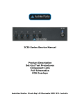
CLASSROOM INFRA RED SYSTEM
INSTRUCTION MANUAL
AVT COMMUNICATION
Systems Ltd.
11 East Butts Road
Rugeley
WS15 2LU
Tel & Fax. (01889) 583158
Customer Orders & Enquiries Lo Call (0845) 766 0800
FREEPOST 1980, Rugeley, WS15 1BR
Registered in England & Wales No. 3117233
ii
INTRODUCTION
ThankyouforselectingtheAzden“RED”infraredsystemasyourwirelesssolution.Weareconfidentthatitwillperform
beyond your expectations. For over 40 years Azden Corporation has been creating technologically advanced products.
BytakingadvantageofthelatestinCADdesignandSMTproductiontechniques,Azden’sengineersareabletoproduce
products that exceed the published specifications and perform well beyond the warranty period.
Azden “RED” represents a breakthrough in wireless. Instead of the normal radio waves that other wireless systems use,
Azden“RED”usesinvisiblelightbeamsintheinfraredrange.Throughtheuseofinfraredyouwillnolongerbeplaguedby
outsideinterference.“RED’s”enhancedperformanceassuresyouofthefinestinaudioclarityandreliability.Thespecially
selectedhigh-frequenciesprovideyouwithtroublefreeperformance,eveninfluorescentlitrooms.Likeallinfrared,Azden
“RED” will not operate correctly outside in the sunlight.
In the real world, the ability to use multiple systems in the same location without frequency interference will prove to be a
tremendousbenefittoyou.Usinginfraredmeansthattheaudiogeneratedinyourroomstaysinyourroom.Yourdiscussions
cannot be overheard on other systems in other rooms.
Designed by professionals - for professionals, Azden “RED” will provide you with years of worry-free, high-quality
performance.
iii
TABLE OF CONTENTS
INFRA-RED RECEIVER
EXPLODED VIEWS . . . . . . . . . . . . . . . . . . . . . . . .
INTRODUCTION . . . . . . . . . . . . . . . . . . . . . . . . . . .
RECEIVER SET UP . . . . . . . . . . . . . . . . . . . . . . . . .
Receiver front panel . . . . . . . . . . . . . . . . . . . . . . . . .
Receiver rear panel . . . . . . . . . . . . . . . . . . . . . . . . . .
Mounting the receiver . . . . . . . . . . . . . . . . . . . . . . . .
Powering the receiver . . . . . . . . . . . . . . . . . . . . . . . .
THE IRB-10 BODY-PACK . . . . . . . . . . . . . . . . . . .
Batteries for the IRB-10 . . . . . . . . . . . . . . . . . . . . . . .
Frequency selection . . . . . . . . . . . . . . . . . . . . . . . . .
Power mode selection . . . . . . . . . . . . . . . . . . . . . . . .
Adjusting MIC gain . . . . . . . . . . . . . . . . . . . . . . . . . .
Using the IRB-10 . . . . . . . . . . . . . . . . . . . . . . . . . . .
Attaching and using the lanyard with the IRE-10 emitter
THE IRH-10 HANDHELD MIC . . . . . . . . . . . . . . . .
Batteries for the IRH-10 . . . . . . . . . . . . . . . . . . . . . . .
Frequency selection . . . . . . . . . . . . . . . . . . . . . . . . .
Using the IRH-10 . . . . . . . . . . . . . . . . . . . . . . . . . . .
THE IRD-10 EXTERNAL SENSOR . . . . . . . . . . . . .
Mounting bracket instruction . . . . . . . . . . . . . . . . . . .
TROUBLESHOOTING . . . . . . . . . . . . . . . . . . . . . .
SPECIFICATIONS . . . . . . . . . . . . . . . . . . . . . . . . .
.
.
.
.
.
.
.
.
.
.
.
.
.
.
.
.
.
.
.
.
.
.
.
.
.
.
.
.
.
.
.
.
.
.
.
.
.
.
.
.
.
.
.
.
.
.
.
.
.
.
.
.
.
.
.
.
.
.
.
.
.
.
.
.
.
.
.
.
.
.
.
.
.
.
.
.
.
.
.
.
.
.
.
.
.
.
.
.
.
.
.
.
.
.
.
.
.
.
.
.
.
.
.
.
.
.
.
.
.
.
.
.
.
.
.
.
.
.
.
.
.
.
.
.
.
.
.
.
.
.
.
.
.
.
.
.
.
.
.
.
.
.
.
.
.
.
.
.
.
.
.
.
.
.
.
.
.
.
.
.
.
.
.
.
.
.
.
.
.
.
.
.
.
.
.
.
.
.
.
.
.
.
.
.
.
.
.
.
.
.
.
.
.
.
.
.
.
.
.
.
.
.
.
.
.
.
.
.
.
.
.
.
.
.
.
.
.
.
.
.
.
.
.
.
.
.
.
.
.
.
.
.
.
.
.
.
.
.
.
.
.
.
.
.
.
.
.
.
.
.
.
.
.
.
.
.
.
.
.
.
.
.
.
.
.
.
.
.
.
.
.
.
.
.
.
.
.
.
.
.
.
.
.
.
.
.
.
.
.
.
.
.
.
.
.
.
.
.
.
.
.
.
.
.
.
.
.
.
.
.
.
.
.
.
.
.
.
.
.
.
.
.
.
.
.
.
.
.
.
.
.
.
.
.
.
.
.
.
.
.
.
.
.
.
.
.
.
.
.
.
.
.
.
.
.
.
.
.
.
.
.
.
.
.
.
.
.
.
.
.
.
.
.
.
.
.
.
.
.
.
.
.
.
.
.
.
.
.
.
.
.
.
.
.
.
.
.
.
.
.
.
.
.
.
.
.
.
.
.
.
.
.
.
.
.
.
.
.
.
.
.
.
.
.
.
.
.
.
.
.
.
.
.
.
.
.
.
.
.
.
.
.
.
.
.
.
.
.
.
.
.
.
.
.
.
.
.
.
.
.
.
.
.
.
.
.
.
.
.
.
.
.
.
.
.
.
.
.
.
.
.
.
.
.
.
.
.
.
.
.
.
.
.
.
.
.
.
.
.
.
.
.
.
.
.
.
.
.
.
.
.
.
.
.
.
.
.
.
.
.
.
.
.
.
.
.
.
.
.
.
.
.
.
.
.
.
.
.
.
.
.
.
.
.
.
.
.
.
.
.
.
.
.
.
.
.
.
.
.
.
.
.
.
.
.
.
.
.
.
.
.
.
.
.
.
.
.
.
.
.
.
.
.
.
.
.
.
.
.
.
.
.
.
.
.
.
.
.
.
.
.
.
.
.
.
.
.
.
.
.
.
.
.
.
.
.
.
.
.
.
.
.
.
.
.
.
.
.
.
.
.
.
.
.
.
.
.
.
.
.
.
.
.
.
.
.
.
.
.
.
.
.
.
.
.
.
.
.
.
.
.
.
.
.
.
.
.
.
.
.
.
.
.
.
.
.
.
.
.
.
.
.
.
.
.
.
.
.
.
.
.
.
.
.
.
.
.
.
.
.
.
.
.
.
. ii
iii
. 1
. 1
. 1
. 1
. 1
. 1
. 1
. 2
. 2
. 2
. 2
. 3
. 3
. 3
. 3
. 4
. 4
. 4
. 5
. 6
AUSTRALIAN MONITOR IC30 - 30W MIXER AMPLIFIER
PRODUCT DESCRIPTION . . .
FRONT PANEL FEATURES . . .
Microphone / Line Level Controls
Bass Control . . . . . . . . . . . . . . .
Treble Control . . . . . . . . . . . . .
Power Switch . . . . . . . . . . . . .
.
.
.
.
.
.
.
.
.
.
.
.
.
.
.
.
.
.
.
.
.
.
.
.
.
.
.
.
.
.
.
.
.
.
.
.
.
.
.
.
.
.
.
.
.
.
.
.
.
.
.
.
.
.
.
.
.
.
.
.
.
.
.
.
.
.
.
.
.
.
.
.
.
.
.
.
.
.
.
.
.
.
.
.
.
.
.
.
.
.
.
.
.
.
.
.
.
.
.
.
.
.
.
.
.
.
.
.
.
.
.
.
.
.
.
.
.
.
.
.
.
.
.
.
.
.
.
.
.
.
.
.
.
.
.
.
.
.
.
.
.
.
.
.
.
.
.
.
.
.
.
.
.
.
.
.
.
.
.
.
.
.
.
.
.
.
.
.
.
.
.
.
.
.
.
.
.
.
.
.
.
.
.
.
.
.
.
.
.
.
.
.
.
.
.
.
.
.
.
.
.
.
.
.
.
.
.
.
.
.
.
.
.
.
.
.
.
.
.
.
.
.
.
.
.
.
.
.
.
.
.
.
.
.
.
.
.
.
.
.
.
.
.
.
.
.
.
.
.
.
.
.
.
.
.
.
.
.
.
.
.
.
.
.
.
.
.
.
.
.
.
.
.
.
.
.
.
.
.
.
.
.
.
.
.
.
.
.
. 8
8
. 8
8
. 8
. 8
REAR PANEL FEATURES . . . . . . . . .
230V/240V Slide Switch . . . . . . . . . . .
AC Power Inlet . . . . . . . . . . . . . . . . . .
Speaker Output Terminal Strip . . . . . . .
Tape Output . . . . . . . . . . . . . . . . . . . .
Microphone / Line Inputs . . . . . . . . . . .
Fuse Sizes . . . . . . . . . . . . . . . . . . . . .
DC Fuse and Amplifier Protection Circuit
.
.
.
.
.
.
.
.
.
.
.
.
.
.
.
.
.
.
.
.
.
.
.
.
.
.
.
.
.
.
.
.
.
.
.
.
.
.
.
.
.
.
.
.
.
.
.
.
.
.
.
.
.
.
.
.
.
.
.
.
.
.
.
.
.
.
.
.
.
.
.
.
.
.
.
.
.
.
.
.
.
.
.
.
.
.
.
.
.
.
.
.
.
.
.
.
.
.
.
.
.
.
.
.
.
.
.
.
.
.
.
.
.
.
.
.
.
.
.
.
.
.
.
.
.
.
.
.
.
.
.
.
.
.
.
.
.
.
.
.
.
.
.
.
.
.
.
.
.
.
.
.
.
.
.
.
.
.
.
.
.
.
.
.
.
.
.
.
.
.
.
.
.
.
.
.
.
.
.
.
.
.
.
.
.
.
.
.
.
.
.
.
.
.
.
.
.
.
.
.
.
.
.
.
.
.
.
.
.
.
.
.
.
.
.
.
.
.
.
.
.
.
.
.
.
.
.
.
.
.
.
.
.
.
.
.
.
.
.
.
.
.
.
.
.
.
.
.
.
.
.
.
.
.
.
.
.
.
.
.
.
.
.
.
.
.
.
.
.
.
.
.
.
.
.
.
.
.
.
.
.
.
.
.
.
.
.
.
.
.
.
.
.
.
.
.
.
.
.
.
.
.
.
.
.
.
.
.
.
.
.
.
.
.
.
.
.
.
.
.
.
.
.
.
.
.
.
.
.
.
.
.
.
.
.
.
.
.
.
.
.
.
.
.
.
.
.
9
9
9
9
10
10
10
10
OPTIONAL ACCESSORIES . . . . . . . . . . . . . . . . . . . . . . . . . . . . . . . . . . . . . . . . . . . . . . . . . . 10
Tone Generators . . . . . . . . . . . . . . . . . . . . . . . . . . . . . . . . . . . . . . . . . . . . . . . . . . . . . . . . . . . . 11
VOX Muting Module . . . . . . . . . . . . . . . . . . . . . . . . . . . . . . . . . . . . . . . . . . . . . . . . . . . . . . . . . 11
iv
Rack Mounting Kit . . . . . . . . . . . . . . . . . . . . . . . . . . . . . . . . . . . . . . . . . . . . . . . . . . . . . . . . . . 11
IMPORTANT SAFETY INFORMATION . . . . . . . . . . . . . . . . . . . . . . . . . . . . . . . . . . . . 12
1
RECEIVER SETUP ( see illustration on page i )
I.
Receiver Front Panel:
A.
Power Switch - turns the receiver On and Off.
B.
Power LED - indicates the power state of the receiver.
C.
Receiving Sensors - internal receiving infrared sensors.
D.
Channel 1 Volume - adjusts the output volume for Channel 1.
E.
Channel 1 Indicator - glows green when receiving Channel 1.
F.
Channel 2 Volume - adjusts the output volume for channel 2.
G.
Channel 2 Indicator - glows green when receiving Channel 2.
II.
Receiver Rear Panel:
H.
Switched External Sensor Input (Phono connector) - Plugging an external
sensor in here turns the front panel sensor (C) off.
I.
2-External Sensor Inputs (Phono connector) - Plugging external sensors in
here extends the receiver’s potential working distance.
J.
Input Selector - selects either Mic (-20dB max @ 1.5K ohms) or Line
(+4dB max @ 1K ohms) level for the output jack (K).
K.
Output Jack - connects the receiver to a mixer or audio amplifier/speaker
combination (1/4 inch unbalanced connector). In general, choose “MIC”
when attaching to a mixer input and “LINE” when attaching to an amplifier
input.
L.
Power Input - plug in AC-AC Adaptor (BC-28i) to power receiver
(12VAC-1.6A)
III.
Mounting the Receiver:
As infrared operates “line-of-sight” and can be interrupted by any solid object, it is
strongly suggested that the receiver (or external sensors) be mounted or placed in a
location that puts the receiving sensors above the audience’s heads or any other
obstacles.
IV.
Powering the Receiver:
The IRR-20 is powered by a BC-28i AC-AC power supply. Before turning the
receiver ON be sure to plug it into an active 220-240V AC wall socket and into the
rear of the IRR-23 (L). DO NOT USE any power supply except the BC-28i.
THE IRB-10 BODY PACK (see illustration on page ii )
I.
Batteries for the IRB-10:
The IRB-10 uses two “AA” batteries for power. They are placed in the battery
compartment (S). After sliding the battery compartment door off, carefully place
FRESH batteries in the compartment in the directions shown on the sticker.
OBSERVE PROPER POLARITY! The IRB-10 can use either Alkaline, Ni-Cad
or Ni-MH batteries. In the case of rechargeable batteries, be sure that they are
FULLY CHARGED before use. Battery life depends on (1) the type of battery
Page 2
used, (2) the power mode chosen and other factors.
II.
Frequency Selection:
The IRB-10 can be set to transmit on either one of two preset frequencies. T his
is so that two different speakers can talk at the same time in the same room. While
it does not matter which frequency is chosen for the body-pack, two transmitters
cannot share the same frequency at the same time. To select the desired frequency
(channel) slide the switch (T) as shown on the sticker on the back of the battery
door.
III.
Power Mode Selection:
The IRB-10 has two Power Modes - Lo and Hi. These modes can be selected via
a switch (Q) inside the battery compartment, and affect two areas related to
performance - battery life and area coverage. If the body-pack is switched to the
Hi position (Q - to the right) the range is set to maximum (approximately 1600
square feet) while the battery life is reduced to approximately 10 hours with Alkaline
batteries. If, on the other hand, the body-pack is switched to Lo the operating
range is reduced to approximately 1200 square feet and the battery life increases to
approximately 15 hours with Alkaline batteries. Experimentation is the only way to
know which position is best for your room.
To avoid ‘blind spots’ use the Hi position
IV.
Adjusting MIC gain:
The MIC gain (volume) is adjustable to compensate for various microphone element
characteristics. The adjustment (R) is located in the battery compartment and can
be adjusted using the provided tool. While speaking into your microphone, adjust
the gain (more gain - clockwise rotation, less gain - anticlockwise rotation) until the
desired volume level is achieved. Best results are normally achieved when the gain
control on the IRB-10 body-pack and the volume control on the IRR-20 receiver
(D or F) are both at their mid-points.
V.
Using the IRB-10:
After inserting fresh batteries, the IRB-10 can be powered by sliding the ON/OFF
Switch (N) to the ON position. The Power LED (O) will glow green when the
IRB-10 is powered ON as will the green LED on the front panel of the IRR-23
which corresponds to the chosen channel. Be sure to slide the Power Switch to
OFF when not in use to preserve battery life.
The emitter (1) must be plugged into the IRB-10 (P) and either attached to the
clothing with the clip (2) or worn around the neck with the lanyard (7) as described
in section VII. The emitter acts as the transmitter and, for best results, should be
worn in such a way as to have a clear path to the receiving sensor(s).
Page 3
VI.
Using the IRB-10 (continued):
While there is a built-in microphone in the emitter, for best results an external
microphone should be used. This microphone can be attached to the IRB-10
through the 3.5mm EXT. MIC jack (M). See page 5 for microphone suggestions.
The internal microphone is disabled when an external mic is attached.
The IRB-10 can be attached to the belt or other clothing by way of the metal belt
clip. It is suggested that the body-pack can be worn in the front portion of the body
to avoid the possibility of damaging it.
VII.
Attaching and Using the Lanyard with the IRE-10 Emitter:
As described above, the emitter can be attached to clothing using the built-in clip
(2). If that is not convenient, or if the built-in auxiliary mic is being used, it is best to
use the included lanyard. To attach, insert the metal clip (2) though the holes (3) on
the lanyard’s clear plastic slide (5).
To adjust the emitter, hold the end of the lanyard (4) and slide the emitter up or
down to the desired position. When using the built-in auxiliary mic it is best to slide
the emitter up as far as possible so that it is close to the mouth (6).
THE IRH-10 HANDHELD MIC (see illustration on page ii)
I.
Batteries for the IRH-10:
The IRH-10 uses two “AA” batteries or one AN-2A Ni-Cd for power. Batteries
are placed in the battery compartment after unscrewing and removing the bottom
portion of the mic handle (W). When using the AN-2A battery (U) carefully place a
FULLY CHARGED battery in the compartment in the direction shown in the
illustration (- to the top, + to the bottom). OBSERVE PROPER POLARITY!
The IRH-10 can also use either 2 “AA” size Alkaline, Ni-Cd or Ni-MH batteries.
When using this size battery, first place the two batteries (Y) into the included
adaptor sleeve (X) and then place in the compartment as shown. Again OBSERVE
PROPER POLARITY! Be sure to use FRESH “AA” Alkaline batteries, or, in the
case of “AA” rechargeable batteries, be sure that they are FULLY CHARGED
before use. Battery life depends on (1) the type of battery used, (2) the power
mode chosen and other factors.
II.
Frequency Selection:
The IRH-10 can be set to transmit on either one of two preset frequencies. This is
so that two different speakers can talk at the same time in the same room. While it
does not matter which frequency is chosen for the handheld mic, two transmitters
cannot share the same frequency at the same time. To select the desired frequency
(channel) slide the switch (V) as shown on the sticker on the side of the battery
Page 4
compartment.
THE IRH-10 HANDHELD MIC (continued).
I.
Using the IRH-10:
After installing fresh batteries and choosing a frequency, simply turn the
mic/transmitter on by sliding the ON/OFF switch up. The red Power LED above the
switch will glow as will the green LED on the front panel of the IRR-23 which
corresponds to the chosen channel. Be sure to slide the Power Switch to OFF when
not in use to preserve battery life.
Best performance is achieved when the mic is held close to the mouth and one
speaks in a normal tone. The mic is designed to be held in the middle of the handle
with the ON/OFF switch facing you. This allows the emitters at the base and near
the mic element to operate at their peak.
THE IRD-10 EXTERNAL SENSOR
To increase the working range of the system, up to three external sensors can be
added, IRD-10 sensors are powered by the receiver and can be plugged into the
“EXT. SENSOR INPUTS” (H and I) on the rear panel. Plugging into inputs 1 and
/or 2 (I) adds to the built-in front sensor (C) and extends the working range by 33
feet in any direction. Plugging into input 3 (H) automatically disconnects the front
panel sensor. This way, if the front panel sensor is blocked (perhaps in a secured
cabinet or closet) it can be replaced. Follow the illustrations below to install the
IRD-10 mounting plate and
sensor.
Page 5
1st
2nd
3rd
Page 6
4th
TROUBLESHOOTING
The single most important thing to ALWAYS check when trouble arises are the batteries.
Make sure they are fresh and the POWER LED is glowing brightly.
SYMPTOM
No POWER LED
No audio from body pack
No audio from handheld mic
Intermittent audio
Limited working range
CAUSE
a. Receiver switch is set to “OFF” - change to “ON”.
b. External 12V AC power source is not connected or is
malfunctioning.
c. Dead of very weak battery in body-pack or handheld.
a. Make sure the volume on the receiver is turned up for the
appropriate channel and the body-pack is powered ON.
b. If two body-packs are being used, make sure they are set
to different frequency channels.
c. If using an external mic, make sure it is plugged in to the
body -pack properly and the internal gain control has been
adjusted.
a. Make sure the volume on the receiver is turned up for the
appropriate channel and the handheld mic is powered ON.
b. If two handheld mics are being used, make sure they are
set to different frequency channels.
a. Make sure there is a clear path between the emitter and
the receiving sensor. Best results are obtained when the
receiving sensors are mounted high - above everyone’s head
a. Install extra external sensors.
b. If using a body-pack, set the Power Mode to Hi.
MICROPHONE SUGGESTIONS
In addition to the IRE-10 emitter’s built-in uni-directional microphone, any one of many fine external
microphones can be used. In the case of head or collar worn mics is that it would be possible to
increase the gain (volume) without adding feedback noise. This is due to the proximity of the mic
element to the speaker’s mouth. Any of the following Azden microphones will produce excellent
results.
EX-503 Omni-directional Lavalier
EX-505U Uni-directional Lavalier
HS-11 Uni-directional Headset
HS-9 Omni-directional Headset
CM-10 Uni-directional Collar-Worn
Page 7
SPECIFICATIONS
System overall
Working range .............................................IRB-10 - 1600 ft² w/built-in sensor
IRH-10 - 2500 ft² w/built-in sensor
Frequency response......................................50Hz - 9kHz (±3dB) body pack (mic dependent)
50Hz - 5kHz (±3dB) auxiliary emitter mic
40Hz - 9kHz (±3dB) handheld
Dynamic range.............................................>100dB
Operating temperature range........................32° - 113°F (0° - 45°C)
Noise reduction............................................2.1 log compander
IRR-20 2-channel receiver
Sub-carrier frequencies................................2.06MHz & 2.56MHz switchable
Type.............................................................super heterodyne - crystal controlled
Modulation..................................................FM
Signal to noise.............................................>90dB
Image rejection............................................>40dB
Reception sensitivity...................................>25dBµV
Reception selectivity...................................±40kHz
Audio output adjustment.............................mic:-20dB max
line:+4dB max
Audio output impendence...........................mic:<1.5k ohms
line:<1k ohms
Power requirement......................................12VAC @ 1.6A
Size..............................................................8.46" W x 8.27" D x 1.73" H (215 x 210 x 44)
Weight.........................................................2.53 lb (1.5 kg)
IRB-10 - channel body pack transmitter
Sub carrier frequencies................................2.06MHz & 2.56MHz switchable
Modulation..................................................FM
Audio distortion..........................................< 1.0% (± 40kHz deviation @ 1kHz)
Mic input impedance...................................2.2k ohms
Mic input jack..............................................3.5mm
Built-in auxiliary mic..................................uni-directional electret
Mic gain adjustment....................................Max to -50dB
Battery type.................................................2 - “AA” alkaline (2 x 1.5V)
2 - “AA” rechargeable Nh-MH or Ni-Cd (2 x 1.2V)
Battery life (100mA drain)..........................>15 hours w/alkaline batteries - low power mode
(160 mA drain)............................>10 hours w/alkaline batteries - high power mode
Size ............................................................3.94" H x 2.52" W x 1.06" D (100 x 64 x 27 mm)
Weight........................................................4.65oz (132g) - transmitter (w/alkaline batteries)
1.34oz (38g) - clip-on emitter
IRH-10 - 2-channel handheld transmitter
Sub-carrier frequencies...............................2.06MHz & 2.56MHz switchable
Modulation.................................................FM
Audio distortion.........................................< 1.0% (± 15kHz deviation @ 1kHz)
Microphone element type...........................uni-directional dynamic
Battery type.................................................2 “AA” alkaline (2 x 1.5V)
2 “AA” rechargeable Ni-MH or Ni-Cd (2 x 1.2V)
1 - Azden AN-2A rechargeable Ni-Cd
Battery life (260mA drain)..........................>10 hours w/alkaline batteries
Size.............................................................10.04" x 2.28" (255 x 58mm)
Weight.........................................................9.0 oz (258g) w/alkaline batteries
Page 8
IRD-10 external sensor
Cable length.................................................32.8' (10m)
Power...........................................................powered by receiver
Size..............................................................2" W x 3" W x 1! H (50.8 x 76.2 x 25.4 mm)
Weight.........................................................4 oz (113.4g)
Mounting.....................................................included metal bracket
Australian Monitor
Installation Series
IC30
30 w Mixer Amplifier
Page 9
IC30, 30 WATT MIXER AMPLIFIER
Product Description
The IC30 is a 30 watt mixer amplifier which operates on 230/240 VAC (115 VAC with factory
modification) or 12 VDC via an external DC power supply source. The amplifier is supplied free
standing with rubber feet but can be rack mounted via an optional rack mount kit (IC30RMK). The
IC30 will deliver 30 watts into a load of 4 ohms, 70 or 100 volt line. The IC30 may be stacked to a
maximum of four units high. An IEC type mains cord and receptacle are provided, the receptacle also
houses the mains fuse in a drawer which pulls open to expose the fuse. A single spare fuse is also located
in this drawer.
Front Panel Features
Microphone/Line Level Controls
The dual mic/line level controls are labelled Ch 1 through to Ch 3 and should be adjusted to provide the
required mix level for each individual channel. Start with the controls set to 0 and turn the controls
clockwise until the desired mix level is achieved.
Bass Control
This control allows the user to increase or decrease the bass response of the system. Adjusting the bass
control in a clockwise direction will provide up to 10dB of bass boost at 100Hz. Adjusting the bass
control in a counter-clockwise direction will provide up to -10dB of bass cut at 100Hz. It is
recommended to start with the bass control at the centre (0) position and adjust if necessary.
Treble Control
Page 10
This control allows the user to increase or decrease the amount of treble in the system. Adjusting the
treble control in a clockwise direction will provide up to 9dB of treble boost at 10kHz. Adjusting the
treble control in a counter-clockwise direction will provide up to -9dB of treble cut at 10kHz. It is
recommended to start with the treble control at the centre (0) position and adjust if necessary.
Power Switch
The power switch controls the switching of AC (mains) power to the amplifier. Rocking this switch
upwards turns on the AC power to the amplifier while rocking the switch downwards turns power off
to the amplifier. When in an upward position and when connected to AC power, the blue LED above
the power switch will illuminate. When running from 12 VDC power, the LED
will not illuminate.
Rear Panel Features
230V/240V Slide Switch
The operating voltage of the amplifier is user selectable between 230V and 240V via a slide switch
located on the top left side of the rear panel. This switch should be set to match the AC voltage of your
country.
AC Power Inlet
The 3 pin IEC power inlet is located on the bottom left of the rear panel and accepts a standard mains
power lead fitted with an IEC connector. Before plugging in a power lead, please check the rear panel
of the amplifier to ensure that the voltage switch is set correctly for your part of the world.
The inlet is equipped with an in-built AC fuse holder fitted with a 1Amp slow blow fuse plus a spare
fuse.
---- Please ensure that the mains power cord is disconnected before attempting to check or
replace this fuse----
Speaker Output Terminal Strip
Located in the middle of the rear panel is the speaker output terminal strip. Spare screw terminals are
provided to allow for the connection of a tone module option. Reading from left to right, the connections
are:
+
-
12 Volts DC positive (+) power connection (for external power supply)
12 Volts DC negative (-) power connection (for external power supply)
Page 11
Spare
COM
4
COM
70
100
Spare
Spare
Mute
Mute
Not used
Common or “-” for low impedance speaker loads
The “+” for 4 ohm speaker loads (use with common)
Common or “-” for 70v or 100v speaker loads (maximum load of 330 ohms at 100v)
The “+” for 70v line speaker loads (use with common)
The “+” for 100v line speaker loads (use with common)
Not used
Not used
Remote Muting On/Off Connection*
Remote Muting On/Off Connection*
* Channels 2 and 3 are muted when the two mute contacts are shorted together. An optional VOX
muting module (TX3010) is also available.
Please ensure that the correct “Common” is used. Low impedance and 70/100v loads can be used
simultaneously but please pay careful attention to the overall speaker load. When used individually, the
low impedance load should be 4 ohms or higher while the 100v line load should not fall below 330
ohms. When both outputs are used simultaneously, ensure that neither output is loaded to maximum.
Tape Output
A line level tape output is provided on the rear panel using an RCA connector. The tape output provides
a maximum of 350mV into 10K ohms making it suitable for connection to most recording devices. Signal
from all three input channels are fed to the tape output. Level adjustments made to the three input
channels will affect the level going to the tape output.
Microphone/Line Inputs
Three universal microphone/line inputs are provided. Microphone inputs are via the 3 pin XLR
connectors while line inputs are via the RCA style connectors (one of each is provided per channel). All
three inputs can be used for microphone and auxiliary input sources. It is also possible to connect both
a microphone and line/aux source to the one channel simultaneously however their relative levels to one
another will be fixed, as there is only one gain control per channel.
The XLR connectors are wired: Pin 1: Earth. Pin 2: Active (high, +), Pin 3: Active (low, -).
Microphone input sensitivity is 1.5mV at 200 ohms.
The RCA connectors have an input sensitivity of 80mV at 47K ohms.
Fuse Sizes
Mains 240 VAC, 1 Ampere Slow Blow
DC Fuse and Amplifier Protection Circuit
The DC fuse is located on the circuit board. This is a feature of the IC30 which is equipped with a
current limiting circuit preventing excessive DC currents, thus eliminating the risk of blowing high tension
fuses. In the unlikely event that the DC fuse actuates, the output IC’s should be checked, as it is
Page 12
probable that the amplifier has been subjected to very extreme conditions.
Optional Accessories
The installation of some of the following accessories involves access to the inside of the amplifier.
Installation should only be attempted by a qualified technician. Always turn off the AC power and
remove the AC power cord before attempting to access the inside of the amplifier. Please contact your
nearest Australian Monitor Installation Series dealer for details of your nearest qualified technician.
Tone Generators
Four separate tones are available as an optional plug in card (ATC5488). The ATC5488 is a small
circuit board which simply plugs into a socket inside the amplifier. Activation is via contact closures
which may be wired to the rear panel of the IC30 or to external switches or a timer. Full installation
instructions are provided with the tone generator.
Tones available on the ATC5488 tone generator board are:
Evacuation Tone (to Australian Standard AS2220.1.2)
Alert Tone (to Australian Standard AS2220.1.2)
Bell Tone
Pre Announce Chime
VOX Muting Module
An optional VOX muting module (TX3010) is available. When installed inside the amplifier, signal on
channel 1 of the amplifier will automatically mute channels 2 and 3. When there is no signal on channel
1, channels 2 and 3 will operate normally. Full installation instructions are provided with the TX3010.
Rack Mounting Kit
An optional rack mounting kit (IC30RMK) is available to mount the IC30 in a standard 19” equipment
rack.
Page 13
Important Safety Information
1. Save the carton and packing material even if the equipment has arrived in good condition.
Should you ever need to ship the unit, use only the original factory packing.
2. Read all documentation before operating your equipment. Retain all documentation for future
reference.
3. Follow all instructions printed on unit chassis for proper operation.
4. Do not spill water or other liquids into or on the unit, or operate the unit while standing in liquid.
5. Make sure power outlets conform to the power requirements listed on the back of the unit.
6. Do not use the unit if the electrical power cord is frayed or broken. The power supply cords
should be routed so that they are not likely to be walked on or pinched by items placed upon or against
them, paying particular attention to cords and plugs, convenience receptacles, and the point where they
exit from the appliance.
7. Always operate the unit with the AC ground wire connected to the electrical system ground.
Precautions should be taken so that the means of grounding of a piece of equipment is not defeated.
8. Mains voltage must be correct and the same as that printed on the rear of the unit. Damage
caused by connection to improper AC voltage is not covered by any warranty.
9. Have gain controls on amplifiers turned down during power-up to prevent speaker damage if
there are high signal levels at the inputs.
10. Power down & disconnect units from mains voltage before making connections.
11. Never hold a power switch in the “ON” position if it won’t stay there itself!
12. Do not use the unit near stoves, heat registers, radiators, or other heat producing devices.
13. Do not block fan intake or exhaust ports. Do not operate equipment on a surface or in an
environment which may impede the normal flow of air around the unit, such as a bed, rug, weather sheet,
carpet, or completely enclosed rack. If the unit is used in an extremely dusty or smoky environment, the
unit should be periodically “blown free” of foreign matter.
Page 14
14. Do not remove the cover. Removing the cover will expose you to potentially dangerous voltages.
There are no user serviceable parts inside.
15. Do not drive the inputs with a signal level greater than that required to drive equipment to
full output.
16. Do not connect the inputs/outputs of amplifiers or consoles to any other voltage source,
such as a battery, mains source, or power supply, regardless of whether the amplifier or console is
turned on or off.
17. Do not run the output of any amplifier channel back into another channel’s input. Do not
parallel or series connect an amplifier output with any other amplifier output.
Audio Telex Communications Pty Ltd is not responsible for damage to loudspeakers for any
reason.
18. Do not ground any red (“hot”) terminal. Never connect a “hot” (red) output to ground or
to another “hot” (red) output!
19. Non-use periods. The power cord of equipment should be unplugged from the outlet when left
unused for a long period of time.
20. Service Information Equipment should be serviced by qualified service personnel when:
A. The power supply cord or the plug has been damaged.
B. Objects have fallen, or liquid has been spilled into the equipment
C. The equipment has been exposed to rain
D. The equipment does not appear to operate normally, or exhibits a marked change in performance
E. The equipment has been dropped, or the enclosure damaged.
Page 15