1
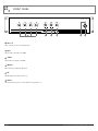
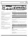
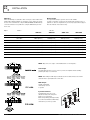
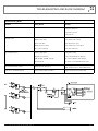
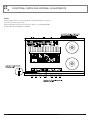
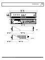
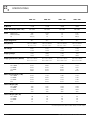
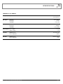
INSTALLATION AND OPERATION MANUAL
AMC+ SERIES
MIXER AMPLIFIERS
AMC+30
AMC+60
AMC+120
AMC+250
IMPORTANT SAFETY INFORMATION
PRÉCAUTIONS DURANT UTILISATION
1.
Read these instructions.
1.
LISEZ ces instructions.
2.
Keep these instructions.
2.
Tenez ces instructions.
3.
Heed all warnings.
3.
Notez tous les avertissements.
4.
Follow all instructions.
4.
Suivez toutes les avertissements.
5.
Do not use this apparatus near water.
5.
N’utilisez pas ce produit près de l’eau (la piscine, la plage, le lac, etc.).
6.
Clean only with dry cloth.
6.
Nettoyez seulement avec une étoffe sèche.
7.
Do not block any ventilation openings. Install in accordance with the
manufacturer’s instructions.
7.
Ne bloquez aucuns troux de ventilation. Installez en accord avec
les instructions du manufacturier.
8.
Do not install near any heat sources such as radiators, heat registers,
stoves, or other apparatus (including amplifiers) that produce heat.
8.
9.
Do not defeat the safety purpose of the polarized or grounding-type plug.
A polarized plug has two blades with one wider than the other.
A grounding type plug has two blades and a third grounding prong.
The wide blade or the third prong are provided for your safety. If the
provided plug does not fit into your outlet, consult an electrician for
replacement of the obsolete outlet.
N’installez près aucunes sources de chaleur comme radiateurs, registres
de chaleur, fours ou les autres équipements (y compris amplificateurs)
qui produisent la chaleur.
9.
Ne défaites pas le but de sécurité de la fiche polarisée ou base-type.
Une fiche polarisée a deux tranchants avec un plus large que l’autre.
Une fiche de base type a deux a deux tranchants et une troisième
pointe de base, le tranchant large ou la troisième pointe est fourni
pour votre sécurité. Si la fiche donnée ne conforme pas votre prise
de contact, consultez un électricien pour remplacement de la prise
de contact obsolète.
10. Protect the power cord from being walked on or pinched particularly
at plugs, convenience receptacles, and the point where they exit from
the apparatus.
11. Only use attachments/accessories specified by the manufacturer.
12. Use only with the cart, stand, tripod, bracket, or table specified by the
manufacturer, or sold with the apparatus. When a cart is used, use caution
when moving the cart/apparatus combination to avoid injury from tip-over.
13. Unplug this apparatus during lightning storms or when
unused for long periods of time.
14. Refer all servicing to qualified service personnel.
Servicing is required when the apparatus has been
damaged in any way, such as power-supply cord or plug
is damaged, liquid has been spilled or objects have fallen into the
apparatus, the apparatus has been exposed to rain or moisture, does
not operate normally, or has been dropped.
15. This appliance shall not be exposed to dripping or splashing water and
that no object filled with liquid such as vases shall be placed on the
apparatus.
16. Plug this apparatus to the proper wall outlet and make the plug to be
disconnected readily operable.
17. Main plug is used as disconnected device and it should remain readily
operable during intended use. In order to disconnect the apparatus from
the mains completely, the mains plug should be disconnected from the
mains socket outlet completely.
18. WARNING: To reduce the risk of fire or electric shock, do not expose this
apparatus to rain or moisture.
19. An appliance with a protective earth terminal should be connected to a
mains outlet with a protective earth connection.
10. Protegez le cordon de secteur contre être marchée dessus ou pincez
en particulier aux fiches, aux douilles de convenance, et au point où ils
sortent de l’appareil.
11. Seulement utilisez attachements/accessoires spécifiés par le
manufacturier.
12. Utilisez seulement avec un chariot, un stand, un trépied, un support
ou une table indiquée par le manufacturier, ou vendue avec l’appareil.
Quand un chariot est utilisé, faites attention en déplaçant la combinaison
d’appareil/chariot pour éviter de se déséquilibrer.
13. Arrachez la fiche du dispositif durant éclair et orage ou
quand pas utilisé pour longues périodes de temps.
14. Référez au personnel qualifié de service pour toutes
réparations. La réparation est donnée quand le système
a été endommagé à n’importe façon, par exemple un fil ou une fiche
endommagé(e) de la source d’alimentation. Avoir été exposé à pluie ou
humidité, n’opère pas normalement, ou avoir été tombé.
15. L’appareil ne doit pas être exposé aux écoulements ou aux éclaboussures
et aucun objet ne contenant de liquide, tel qu’un vase, ne doit être placé
sur l’objet.
16. Branchez l’appareil à une source appropriée et faire que la prise à
débrancher soit facilement accessible.
17. La prise du secteur ne doit pas être obstruée ou doit être facilement
accessible pendant son utilisation. Pour être complètement déconnecté
de l’alimentation d’entrée, la prise doit être débranchée du secteur.
18. AVERTISSEMENT: Pour éviter le risque d’incendie ou de chocs électriques,
ne pas exposer cet appareil à la pluie ou à l’humidité.
19. Un appareil avec la borne de terre de protection doit être connecté au
secteur avec la connexiion de terre de protection.
PAGE 2
AMC+ SERIES INSTALLATION AND OPERATION MANUAL
INTRODUCTION AND CONTENTS
AMC+ SERIES
INTRODUCTION
3
The Australian Monitor AMC+ series of amplifiers takes the heritage
and reliability of our famous AMIS series amplifiers and integrates
these features into low cost amplifiers for applications where
reliability is everything, but the more elaborate features of our AMIS
series are not required.
FRONT PANEL
4
REAR PANEL
5
INSTALLATION
6
TROUBLESHOOTING AND BLOCK DIAGRAM
7
Available in 30, 60, 120 and 250 watt versions, the AMC+ series
are 2 RU mixer amplifiers, featuring 70/100 volt line and 4 ohm
outputs, and 4 universal
mic/line inputs.
FUNCTIONAL NOTES AND INTERNAL ADJUSTMENTS 8
Master volume and overall treble and bass controls are provided,
along with Vox triggered muting (defeatable), giving channel 1
priority over inputs 2, 3 and 4. There is also the facility to add a tone
generator card.
DIMENSIONS
9
SPECIFICATIONS
10 – 11
The Australian Monitor AMC+ series gives the contractor a low cost
alternative in applications that are price sensitive, but still require a
high quality of sound reproduction and reliability.
Revision 1.6 July 2010
WARNING!
TO PREVENT FIRE OR SHOCK HAZARD, DO NOT USE THE PLUG WITH
AN EXTENSION CORD, RECEPTACLE OR OTHER OUTLET UNLESS THE BLADES
CAN BE FULLY INSERTED TO PREVENT BLADE EXPOSURE.
TO REDUCE THE RISK OF FIRE OR ELECTRIC SHOCK, DO NOT EXPOSE
THIS APPLIANCE TO RAIN OR MOISTURE.
TO PREVENT ELECTRICAL SHOCK, MATCH WIDE BLADE PLUG TO WIDE SLOT, FULLY INSERT.
CAUTION
RISK OF ELECTRIC SHOCK
DO NOT OPEN
The lightning flash with arrowhead symbol,
within an equilateral triangle, is intended
to alert the user to the presence of
uninsulated “dangerous voltage” within
the product’s enclosure that may be of
sufficient magnitude to constitute a risk
of electric shock to persons.
WARNING: TO REDUCE THE RISK
OF ELECTRIC SHOCK, DO NOT
REMOVE COVER (OR BACK).
NO USER SERVICEABLE PARTS INSIDE.
REFER SERVICING TO QUALIFIED
SERVICE PERSONNEL.
The exclamation point within an equilateral
triangle is intended to alert the user to
the presence of important operating and
maintenance (servicing) instructions in the
literature accompanying the appliance.
Rating plate and caution marking are marked on the back enclosure of the apparatus
AMC+ SERIES INSTALLATION AND OPERATION MANUAL
PAGE 3
FRONT PANEL
1
2
3
4
5
6
1 CH 1–4
These control the levels for each channel input.
2 Bass
There is 12dB of cut and boost at 100Hz.
3 Treble
There is 9dB of cut and boost at 10kHz.
4 Master
This controls the overall mixed output level.
5 On
This LED indicates the unit is powered “on”.
6 Power
This switch switches power on or off the mains. The up position is on.
PAGE 4
AMC+ SERIES INSTALLATION AND OPERATION MANUAL
REAR PANEL
5
4
7
6
1 CH 1–4
Each channel input section has two inputs: XLR input – This
is a balanced microphone input. It has an input sensitivity of
1mV. RCA input – This is an unbalanced line level input. It
has an input sensitivity of 150mV. The two RCA sockets are
summed to mono internally.
3
2
Minimum Impedance
1
AMC+30
AMC+60
AMC+120
AMC+250
166ohm
333ohm
83ohm
166ohm
41ohm
83ohm
20ohm
40ohm
4ohm
4ohm
4ohm
4ohm
Distributed Line Output
70V (115V version)
100V (230/240V version)
Low Impedance Output
2 REC Output
The REC output is on unbalanced RCA connectors. The output
level is 150mV into 10kohm at rated output. The output is
dual mono.
The REC output is not affected by the MASTER volume control
or the BASS and TREBLE controls.
The REC output does not receive the tone signal if the
optional tone generator module is installed.
(both versions)
Note: Only connect one output – either Distributed Line or Low Impedance per channel.
Do not connect LowZ and 70/100V at the same time.
The output strip comes fitted with a touch-proof cover held in place by two M3 machine screws
with flat and spring washers.
5
3 Line Output
The LINE output is on a balanced XLR connector. The output
level is 0.775V into 1k at rated output.
Note: When wiring the LINE output as unbalanced, Pin2
should be wired as hot and Pin1 should be wired as ground/
shield. Do not wire Pin3.
4 Direct Out
IEC Mains Input Socket
This is a standard IEC 3 pin socket. It accepts a standard IEC mains cable, provided. The fuse
draw at 5 contains the mains fuse and a spare. The mains fuse is a time lag (slow blow)
HRC 20mm x 5mm ceramic type fuse.
The ratings are:
230V/240V model
115V model
AMC+30
AMC+60
AMC+120
AMC+250
0.5A
1.6A
2A
3.15A
1A
3.15A
4A
6.3A
Always replace the fuse with one of the same value and type.
The speaker connections are on the 12 pole terminal strip.
There is a low impedance output (OHM) and a distributed line
voltage output (LINE). 70V out is available on 115V models.
100V out is available on 230V/240V models.
Note: Always disconnect power to the amplifier before replacing fuses.
6 (Optional) Tone Module
These terminals are for use with an optional tone module (not supplied). Use Australian Monitor
ATC5488 module.
7
Phantom Power
12V phantom power is available for condenser or electret microphones on the XLR input when
this switch is pushed in.
AMC+ SERIES INSTALLATION AND OPERATION MANUAL
PAGE 5
INSTALLATION
Mounting
When rack mounting, it is advisable to allow 1 rack space above and below the
amplifier. When multiple amplifiers are mounted in a rack, exhaust fans should
be used on the rack. Airflow for cooling the AMC30, AMC60 and AMC120 is by
convection from bottom to top. Airflow for cooling the AMC250 is by fan from
front to side.
Output
Distance
Wire Size
+
100V
70V
4 ohm
Direct Output
The output terminal strip accepts wire sizes from 16-22AWG
(1.5mm2 – 0.35mm2) or spade lugs. The following table should be used as a
guideline for cable sizes. Regulations in your area may require different gauged
wire and should be checked before using.
AMC 30
AMC+60
AMC+120
AMC+250
Up to 50m
AWG26(0.12mm2)
AWG26(0.12mm2)
AWG24(0.2mm2)
AWG22(0.35mm2)
50m–200m
AWG24(0.2mm2)
AWG20(0.5mm2)
AWG18(0.75mm2)
AWG16(1.5mm2)
Over 200m
AWG20(0.5mm2)
AWG18(0.75mm2)
AWG16(1.5mm2)
AWG13(2.5mm2)
Up to 50m
AWG26(0.12mm2)
AWG24(0.2mm2)
AWG22(0.35mm2)
AWG18(0.75mm2)
50m–200m
AWG20(0.5mm2)
AWG18(0.75mm2)
AWG16(1.5mm2)
AWG13(2.5mm2)
Over 200m
AWG18(0.75mm2)
AWG16(1.5mm2)
AWG13(2.5mm2)
AWG10(6.0mm2)
Up to 10m
AWG18(0.75mm2)
AWG18(0.75mm2)
AWG18(0.75mm2)
AWG18(0.75mm2)
10m–30m
AWG13(2.5mm2)
AWG13(2.5mm2)
AWG13(2.5mm2)
AWG13(0.35mm2)
Over 30m
Not Recommended
Not Recommended
Not Recommended
Not Recommended
NOTE: Only connect one output – either Distributed Line or Low Impedance.
Line Output
The LINE output XLR can be used to connect up to 6 booster amplifiers. Balanced wiring
(shielded pair cable) is recommended.
NOTE: When wiring the LINE output as unbalanced, Pin2 should be wired as hot and Pin1
should be wired as ground/shield. Do not wire Pin3.
REC Output
The REC output wiring
should be kept as short
as possible.
Input Connections
For wiring balanced in, pin 2 is hot.
Unbalanced wiring on the microphone
inputs is not recommended.
Balanced input wiring (shielded pair cable)
is recommended. Unbalanced RCA wiring
should be keep as short as possible.
PAGE 6
AMC+ SERIES INSTALLATION AND OPERATION MANUAL
TROUBLESHOOTING AND BLOCK DIAGRAM
Troubleshooting Guide
Trouble
Likely Cause
Remedy
Power LED not on
Power not reaching amplifier
Check power switch is on
Check mains connection
Check mains fuse
Distorted sound
Output is short circuit
Check speaker loads for shorts
Input is overloaded
Reduce input level at source
Output is being over driven
Reduce volume levels on front panel
Bass control is turned up
Reduce Bass control level
Volume controls down
Check volume controls
Amplifier has overheated
(AMC+60, AMC+120 AMC+250 only)
Check for obstructions above and below
Make sure the amplifier is well ventilated
DC fuse(s) blown
Refer product to local Australian Monitor dealer
No sound from channels 2 and 3
Priority function is being used
Remove signal (disconnect input) from channel 1 OR
Disable priority function (see Internal Adjustments)
Tones do not sound when triggered
Tone generator module not installed
Purchase optional Tone generator module
No sound but amp is on
AMC+ SERIES INSTALLATION AND OPERATION MANUAL
PAGE 7
FUNCTIONAL NOTES AND INTERNAL ADJUSTMENTS
Priority
Channel 1 will mute channels 2, 3 and 4. This will only occur when signal appears on channel 1,
irrespective of the channel volume control.
Priority can be disabled. (See below). The release time is approx. 3 secs and is NOT adjustable.
The mute depth is approx. 40dB and is not adjustable.
PAGE 8
AMC+ SERIES INSTALLATION AND OPERATION MANUAL
DIMENSIONS
AMC+ SERIES INSTALLATION AND OPERATION MANUAL
PAGE 9
SPECIFICATIONS
AMC+ 30
AMC+ 60
AMC+ 120
AMC+ 250
30W
60W
120W
250W
> 75dBr
> 75dBr
> 80dBr
>85dBr
85Hz-15kHz
75Hz-15kHz
75Hz-15kHz
30Hz-20kHz
1.0A
0.5A
1.6A (x2)
3.15A
1.6A
4A
4A
2A
8A
6.3A
3.15A
10A (x2)
96%
93%
93%
90%
482 x 88 x 190mm
19” x 3.5” x 7.5”
482 x 88 x 281mm
19” x 3.5” x 11.1”
482 x 88 x 281mm
19” x 3.5” x 11.1”
482 x 88 x 384mm
19” x 3.5” 15.1”
Net Weight
6.0kg
13.2lb
8.5kg
18.7lb
10.5kg
23.1lb
11.5kg
25.3lb
Shipping Weight
7.5kg
16.5lb
10.5kg
23.1lb
12.5kg
27.6lb
14kg
30.8lb
510 x 145 x 297mm
20.1” x 5.7” x 11.7”
525 x 175 x 385mm
20.7” x 6.9” x 15.2”
525 x 175 x 385mm
20.7” x 6.9” x 15.2”
525 x 185 x 470mm
20.7” x 7.3” x 18.5”
Mains Current Draw (240v)
FULL POWER
1/3 POWER
1/8 POWER
IDLE
0.35A
0.23A
0.17A
0.08A
0.66A
0.44A
0.32A
0.13A
1.20A
0.80A
0.55A
0.15A
2.53A
1.61A
1.10
0.15A
Mains Current Draw (115v)
FULL POWER
1/3 POWER
1/8 POWER
IDLE
0.73A
0.48A
0.35A
0.17A
1.38A
0.92A
0.67A
0.27A
2.50A
1.67A
1.15A
0.31A
5.28A
3.36A
2.30A
0.31A
Thermal Output (W)
FULL POWER
1/3 POWER
1/8 POWER
IDLE
38W
33W
26W
11W
67W
63W
51W
19W
128W
118W
91W
26W
259W
231W
168W
26W
Thermal Output (Btu/Hr)
FULL POWER
1/3 POWER
1/8 POWER
IDLE
130
113
90
38
229
215
172
65
437
403
311
89
884
788
573
89
Power Output (0.5%Thd, 1khz)
S/N Ratio
Power Bandwidth (-3db +1db)
Fuses
MAINS (115V)
MAINS (230/240V)
DC
Output Regulation
Size (Wxhxd)
Shipping Dimensions (Wxhxd)
*1/3 and 1/8 power levels relate to voltage changes, not load changes.
PAGE 10
AMC+ SERIES INSTALLATION AND OPERATION MANUAL
SPECIFICATIONS
COMMON TO ALL MODELS
Thd (1khz, -1db)
Better than 0.5%
Mic Input
SENSITIVITY
IMPEDANCE
HEADROOM
1mV @ 200ohm
1k3 ohm
77mV (37dB)
Aux Input
SENSITIVITY
IMPEDANCE
HEADROOM
150mV
>200kohm
> 15V (>40dB)
Tone Control BASS @ 100HZ
TREBLE @ 10KHZ
+/- 12 dB
+/- 9 dB
Line Out
NOMINAL OUTPUT
OUTPUT IMPEDANCE
0.775V @ 1kohm
100ohm
Rec Out
NOMINAL OUTPUT
OUTPUT IMPEDANCE
250mV @ 10kohm
1kohm
AMC+ SERIES INSTALLATION AND OPERATION MANUAL
PAGE 11
ENGINEERED BY AUSTRALIAN MONITOR
Address: 1 Clyde Street, Silverwater, Sydney NSW 2128 Australia. Private Bag 149, Silverwater NSW 1811 ABN 78 001 345 482
Website: www.australianmonitor.com.au International enquiries email: [email protected]
DISTRIBUTED IN AUSTRALIA AND NEW ZEALAND BY HILLS SVL www.hillssvl.com.au
NSW
P: 02 9647 1411
E: [email protected]
QLD
P: 07 3852 1312
E: [email protected]
ACT
P: 02 6260 4544
E: [email protected]
WA
P: 08 9204 0200
E: [email protected]
VIC
P: 03 9890 7477
E: [email protected]
SA
NZ
P: 08 8408 8300
P: 09 415 9426
E: [email protected] E: [email protected]