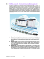
1
User Manual AIMB-201DS Intel® Core™ i7/i5/i3/Celeron uFC-PGA988 Mini-ITX with 3 HDMI(CEC) - Digital Signage Copyright The documentation and the software included with this product are copyrighted 2013 by Advantech Co., Ltd. All rights are reserved. Advantech Co., Ltd. reserves the right to make improvements in the products described in this manual at any time without notice. No part of this manual may be reproduced, copied, translated or transmitted in any form or by any means without the prior written permission of Advantech Co., Ltd. Information provided in this manual is intended to be accurate and reliable. However, Advantech Co., Ltd. assumes no responsibility for its use, nor for any infringements of the rights of third parties, which may result from its use. Acknowledgements IBM, PC/AT, PS/2 and VGA are trademarks of International Business Machines Corporation. Intel® and CoreTM are trademarks of Intel Corporation. Microsoft Windows® is a registered trademark of Microsoft Corp. AMI is a registered trademark of American Megatrends Inc. ESS is a trademark of ESS Technology, Inc. UMC is a trademark of United Microelectronics Corporation. SMI is a trademark of Silicon Motion, Inc. Creative is a trademark of Creative Technology LTD. CHRONTEL is a trademark of Chrontel Inc. All other product names or trademarks are properties of their respective owners. For more information about this and other Advantech products, please visit our website at: http://www.advantech.com/ For technical support and service, please visit our support website at: http://support.advantech.com.tw/support/ AIMB-201DS User Manual Part No. 2006A20100 Edition 1 Printed in China January 2013 ii Product Warranty (2 years) Advantech warrants to you, the original purchaser, that each of its products will be free from defects in materials and workmanship for two years from the date of purchase. This warranty does not apply to any products which have been repaired or altered by persons other than repair personnel authorized by Advantech, or which have been subject to misuse, abuse, accident or improper installation. Advantech assumes no liability under the terms of this warranty as a consequence of such events. Because of Advantech’s high quality-control standards and rigorous testing, most of our customers never need to use our repair service. If an Advantech product is defective, it will be repaired or replaced at no charge during the warranty period. For outof-warranty repairs, you will be billed according to the cost of replacement materials, service time and freight. Please consult your dealer for more details. If you think you have a defective product, follow these steps: 1. Collect all the information about the problem encountered. (For example, CPU speed, Advantech products used, other hardware and software used, etc.) Note anything abnormal and list any onscreen messages you get when the problem occurs. 2. Call your dealer and describe the problem. Please have your manual, product, and any helpful information readily available. 3. If your product is diagnosed as defective, obtain an RMA (return merchandize authorization) number from your dealer. This allows us to process your return more quickly. 4. Carefully pack the defective product, a fully-completed Repair and Replacement Order Card and a photocopy proof of purchase date (such as your sales receipt) in a shippable container. A product returned without proof of the purchase date is not eligible for warranty service. 5. Write the RMA number visibly on the outside of the package and ship it prepaid to your dealer. iii AIMB-201DS User Manual Declaration of Conformity FCC Class B Note: This equipment has been tested and found to comply with the limits for a Class B digital device, pursuant to part 15 of the FCC Rules. These limits are designed to provide reasonable protection against harmful interference in a residential installation. This equipment generates, uses and can radiate radio frequency energy and, if not installed and used in accordance with the instructions, may cause harmful interference to radio communications. However, there is no guarantee that interference will not occur in a particular installation. If this equipment does cause harmful interference to radio or television reception, which can be determined by turning the equipment off and on, the user is encouraged to try to correct the interference by one or more of the following measures: Reorient or relocate the receiving antenna. Increase the separation between the equipment and receiver. Connect the equipment into an outlet on a circuit different from that to which the receiver is connected. Consult the dealer or an experienced radio/TV technician for help. CPU Compatibility CPU Family Speed Core Stepping TDP L3 cache Intel i7-3610QE 2.3 GHz D-4 45 W 6 MB Intel i7-2710QE 2.1 GHz D-4 45 W 6 MB Intel i5-3610ME 2.7 GHz D-2 35 W 3 MB Intel i5-2510E 2.5 GHz D-2 35 W 3 MB Intel i3-3120ME 2.4 GHz D-2 35 W 3 MB Intel i3-2330 2.2 GHz D-2 35 W 3 MB Intel Celeron B810 1.6 GHz D-2 35 W 2 MB AIMB-201DS User Manual iv Memory Compatibility Test Item Description Brand Size Speed Type Result Remark ECC Vendor PN Memory Transcend 1GB DDR3 SODIMM N 1066 DDR3 TS128MS K64V1U SEC K4B1G0846GBCH9 PASS Transcend 2GB DDR3 SODIMM N 1066 DDR3 TS128MS K64V1U SEC HCH9 K4B1G0846D (128x8) PASS Transcend 4GB DDR3 SODIMM N 1066 DDR3 HYNIX TS7KSN28 H5TQ2G83BFR 420-1Y (256x8) PASS Apacer 4GB DDR3 SODIMM N 1066 DDR3 HYNIX 78.B2GC8. H5TQ2G83BFR AF1 (256x8) PASS Transcend 1GB DDR3 SODIMM N 1333 DDR3 TS128MS K64V3U ELPIDA J1108BFBG-DJ-F PASS Transcend 2GB DDR3 SODIMM N 1333 DDR3 TS256MS K64V3N HYNIX H5TQ2G83CFR PASS Transcend 4GB DDR3 SODIMM N 1333 DDR3 TS512MS K64V3N HYNIX H5TQ2G83BFR (256x8) PASS Transcend 8GB DDR3 SODIMM N 1333 DDR3 TS1GSK6 MICRON IVD22 4V3H D9PBC PASS Apacer 1GB DDR3 SODIMM N 1333 DDR3 HYNIX 78.02GC6. H5TQ1G83DFRAF0 H9C PASS 1GB DDR3 SODIMM N 1333 DDR3 HYNIX H5TQ1G83TFRH9C PASS Apacer 2GB DDR3 SODIMM N 1333 DDR3 78.A2GC9. ELPIDA 4200C J2108BCSE-DJ-F PASS Apacer 4GB DDR3 SODIMM N 1333 DDR3 HYNIX 78.B2GC9. H5TQ2G83BFR AF1 (256x8) PASS Apacer 4GB DDR3 SODIMM N 1333 DDR3 78.B2GC9. ELPIDA 4210C J2108BCSE-DJ-F PASS DSL 4GB DDR3 SODIMM N 1333 DDR3 HYNIX D3SH5608 H5TQ2G83BFR 2XH15AA (256x8) PASS DSL 2GB DDR3 SODIMM N 1600 DDR3 SEC 113 HCK0 D3SS5608 K4B2G0846C 1XH12AA (256x8) PASS DSL 4GB DDR3 SODIMM N 1600 DDR3 SEC 113 HCK0 D3SS5608 K4B2G0846C 2XH12AA (256x8) PASS Transcend 2GB DDR3 SODIMM N 1600 DDR3 TS256MS K64V6N MICRON IVM77 D9PFJ PASS Transcend 4GB DDR3 SODIMM N 1600 DDR3 TS512MS K64N6N MICRON IRM72 D9PFJ PASS v AIMB-201DS User Manual Ordering Information Part Number Chipset HDMI CRT USB COM LAN STOREAGE AIMB-201VG-DSA1E QM77 3 3 (1) 1 1 1*SATA 3.0, CFast, MiniPCIe Technical Support and Assistance 1. 2. Visit the Advantech website at http://support.advantech.com where you can find the latest information about the product. Contact your distributor, sales representative, or Advantech's customer service center for technical support if you need additional assistance. Please have the following information ready before you call: – Product name and serial number – Description of your peripheral attachments – Description of your software (operating system, version, application software, etc.) – A complete description of the problem – The exact wording of any error messages Warnings, Cautions and Notes Warning! Warnings indicate conditions, which if not observed, can cause personal injury! Caution! Cautions are included to help you avoid damaging hardware or losing data. e.g. There is a danger of a new battery exploding if it is incorrectly installed. Do not attempt to recharge, force open, or heat the battery. Replace the battery only with the same or equivalent type recommended by the manufacturer. Discard used batteries according to the manufacturer's instructions. Note! Notes provide optional additional information. AIMB-201DS User Manual vi Safety Instructions 1. 2. 3. Read these safety instructions carefully. Keep this User Manual for later reference. Disconnect this equipment from any AC outlet before cleaning. Use a damp cloth. Do not use liquid or spray detergents for cleaning. 4. For plug-in equipment, the power outlet socket must be located near the equipment and must be easily accessible. 5. Keep this equipment away from humidity. 6. Put this equipment on a reliable surface during installation. Dropping it or letting it fall may cause damage. 7. The openings on the enclosure are for air convection. Protect the equipment from overheating. DO NOT COVER THE OPENINGS. 8. Make sure the voltage of the power source is correct before connecting the equipment to the power outlet. 9. Position the power cord so that people cannot step on it. Do not place anything over the power cord. 10. All cautions and warnings on the equipment should be noted. 11. If the equipment is not used for a long time, disconnect it from the power source to avoid damage by transient overvoltage. 12. Never pour any liquid into an opening. This may cause fire or electrical shock. 13. Never open the equipment. For safety reasons, the equipment should be opened only by qualified service personnel. 14. If one of the following situations arises, get the equipment checked by service personnel: The power cord or plug is damaged. Liquid has penetrated into the equipment. The equipment has been exposed to moisture. The equipment does not work well, or you cannot get it to work according to the user's manual. The equipment has been dropped and damaged. The equipment has obvious signs of breakage. 15. DO NOT LEAVE THIS EQUIPMENT IN AN ENVIRONMENT WHERE THE STORAGE TEMPERATURE MAY GO BELOW -20° C (-4° F) OR ABOVE 60° C (140° F). THIS COULD DAMAGE THE EQUIPMENT. THE EQUIPMENT SHOULD BE IN A CONTROLLED ENVIRONMENT. 16. CAUTION: DANGER OF EXPLOSION IF BATTERY IS INCORRECTLY REPLACED. REPLACE ONLY WITH THE SAME OR EQUIVALENT TYPE RECOMMENDED BY THE MANUFACTURER, DISCARD USED BATTERIES ACCORDING TO THE MANUFACTURER'S INSTRUCTIONS. The sound pressure level at the operator's position according to IEC 704-1:1982 is no more than 70 dB (A). DISCLAIMER: This set of instructions is given according to IEC 704-1. Advantech disclaims all responsibility for the accuracy of any statements contained herein. vii AIMB-201DS User Manual Packing List Before installation, please ensure the following items have been shipped: 1 x AIMB-201DS motherboard 2 x I/O port bracket 1 x Startup manual 1 x Driver CD Optional Power Cord & Accessories Part Number 1757003734 1700019384 1700017999 1960057850T001 1960051292N001 1700003195 1700002204 AIMB-201DS User Manual Description ADAPTER 100-240V 65W 19V 3.42A SATA power cable 30cm SATA power cable 17cm Heat Pipe CPU Cooler USB cable with two ports, 17.5 cm USB cable with two ports, 27 cm viii Contents Chapter 1 General Introduction ...........................1 1.1 1.2 Introduction ............................................................................................... 2 Product Features....................................................................................... 2 1.2.1 General ......................................................................................... 2 1.2.2 Display .......................................................................................... 2 1.2.3 Power Consumption...................................................................... 2 Hardware Specifications ........................................................................... 2 Board Layout............................................................................................. 3 1.4.1 Dimensions ................................................................................... 3 1.4.2 Weight........................................................................................... 3 AIMB-201DS Block Diagram..................................................................... 4 Power Requirements................................................................................. 4 1.6.1 System Power............................................................................... 4 1.6.2 RTC Battery .................................................................................. 4 Environmental Specifications .................................................................... 4 1.7.1 Operating Temperature................................................................. 4 1.7.2 Relative Humidity .......................................................................... 4 1.7.3 Storage Temperature.................................................................... 4 1.7.4 EMC .............................................................................................. 4 Jumper Settings ........................................................................................ 5 1.8.1 How to Set Jumpers...................................................................... 5 1.8.2 CMOS Clear (CMOS1) ................................................................. 5 Table 1.1: CMOS1....................................................................... 5 1.8.3 PSON1: ATX, AT Mode Selector .................................................. 5 Table 1.2: PSON1: ATX, AT Mode Selector................................ 5 1.3 1.4 1.5 1.6 1.7 1.8 Chapter 2 Hardware Installation ..........................7 2.1 AIMB-201DS I/O Connectors .................................................................... 8 Figure 2.1 Front and rear view..................................................... 8 AIMB-201DS Front Side External I/O Connectors .................................... 8 2.2.1 Power ON/OFF Button.................................................................. 8 Figure 2.2 Power button .............................................................. 8 2.2.2 COM Connector ............................................................................ 8 Figure 2.3 COM connector .......................................................... 8 Table 2.1: COM Port Pin Assignments........................................ 9 2.2.3 USB Connectors ........................................................................... 9 Figure 2.4 USB connector ........................................................... 9 Table 2.2: USB Port Pin Assignments......................................... 9 AIMB-201DS Rear Side External I/O Connectors................................... 10 2.3.1 Audio Connector ......................................................................... 10 Figure 2.5 Audio connector........................................................ 10 2.3.2 Ethernet Connector (LAN) .......................................................... 10 Figure 2.6 LAN connector.......................................................... 10 Table 2.3: LAN Connector Pin Assignments ............................. 10 2.3.3 HDMI Connector ......................................................................... 11 Figure 2.7 HDMI connector........................................................ 11 Table 2.4: HDMI Connector Pin Assignments ........................... 11 2.3.4 Power Input Connector ............................................................... 11 Figure 2.8 DC input connector................................................... 11 2.2 2.3 Chapter 3 BIOS Settings.....................................13 ix AIMB-201DS User Manual 3.1 3.2 BIOS Introduction.................................................................................... 14 Main Setup.............................................................................................. 14 3.2.1 System Time / System Date ....................................................... 14 Figure 3.1 Main Setup Screen................................................... 14 3.2.2 Advanced BIOS Features Setup................................................. 15 Figure 3.2 Advanced BIOS Features Setup Screen.................. 15 Figure 3.3 S5 RTC Setup Screen.............................................. 16 Figure 3.4 CPU Setup screen.................................................... 17 Figure 3.5 SATA Setup screen.................................................. 17 Figure 3.6 Intel Anti-Theft Technology Configuration ................ 18 Figure 3.7 AMT Configuration setup screen.............................. 19 Figure 3.8 USB Configuration setup screen .............................. 20 Figure 3.9 Embedded Controller Configuration setup screen ... 21 Figure 3.10Serial Port 0 Configuration setup screen.................. 22 Figure 3.11H/W monitor screen.................................................. 22 Figure 3.12CPU PPM Configuration setup screen ..................... 23 3.2.3 Chipset BIOS Feature Setup ...................................................... 24 3.2.4 Boot BIOS Feature Setup ........................................................... 24 Figure 3.13Boot configuration setup screen............................... 24 3.2.5 Security BIOS Feature Setup ..................................................... 25 Figure 3.14Security configuration setup screen ......................... 25 3.2.6 Save & Exit BIOS Feature Setup................................................ 26 Figure 3.15Save & Exit configuration setup screen.................... 26 4 Software Introduction & Service ..... 27 4.1 4.2 Introduction ............................................................................................. 28 Value-Added Software Services ............................................................. 28 4.2.1 Software API............................................................................... 28 4.2.2 Software Utility............................................................................ 30 5 Chipset Software Installation Utility 31 5.1 5.2 5.3 Before You Begin.................................................................................... 32 Introduction ............................................................................................. 32 Windows XP/Windows 7 Driver Setup .................................................... 33 6 VGA Setup ......................................... 35 6.1 6.2 Introduction ............................................................................................. 36 Windows 7/XP......................................................................................... 36 7 LAN Configuration ............................ 39 7.1 7.2 7.3 7.4 Introduction ............................................................................................. 40 Features.................................................................................................. 40 Installation............................................................................................... 40 Windows® 7/XP Driver Setup (Intel 82579LM)....................................... 40 Appendix A SUSIAccess Introduction ................. 41 A.1 SUSIAccess® - Remote Device Management........................................ 42 Chapter Chapter Chapter Chapter AIMB-201DS User Manual x Chapter 1 1 General Introduction This chapter gives background information of AIMB-201DS series. 1.1 Introduction AIMB-201DS is powered by 3rd Gen Intel® Core™ i7/i5/i3 processors with Intel® HD Graphics for Full HD video playback performance. AIMB-201DS is a media player that delivers advanced graphics performance for all your signage applications. AIMB-201DS has 3 HDMI video output interfaces with CEC function to provide multi display outputs simultaneously. For better connectivity, it supports internal 1 x Mini PCIe interface for add-on functions such as wireless network and TV tuner cards to fulfill different requirements. And it also supports 1 x USB 3.0, 2 x USB 2.0, 1 x COM (RS-232) ports for system integration and applications. 1.2 Product Features 1.2.1 General Supports 3rd Gen. Intel® Core™ i7/i5/i3 mobile CPUs. Socket type is rPGA 988B (CPU TDP up to 45W) Supports 3 HDMI (w/ CEC) ports for multiple displays Supports 1 x GbE , 1 x USB 3.0, 2 x USB 2.0 and 1 x COM (RS-232) Internal 2.5-inch SATA HDD drive bay and Cfast slot for storage devices. Built-in MiniPCIe slot for easy expansion e.g. WiFi, TV-tuner, etc Easy integration and easy maintenance 1.2.2 Display Multi-display support; up to 2x1080P and 1x 720P video playback performance (but subject to the video media format and playback software) 1.2.3 Power Consumption Typical: 17.4 W (3rd Gen. Intel® Core™ i7-3610QE 2.3 GHz and w/o expansion) Max.: 43.8 W (3rd Gen. Intel® Core™ i7-3610QE 2.3 GHz and w/o expansion) 1.3 Hardware Specifications CPU: 3rd Gen. Intel® Core™ i7/i5/i3 mobile CPUs. Socket type is rPGA 988B System Chipset: Intel® QM77 BIOS: AMI 16-Mbit Flash BIOS System Memory: 2 x DDR3 SO-DIMM sockets, support DDR3 1333 MHz up to 16 GB (Max. 8GB per each SO-DIMM socket) Graphic chipset: Integrated in Intel® Core™ i CPU SSD: Supports 1 x Cfast slot HDD: Supports 1 x 2.5" SATA HDD Watchdog Timer: Supported by Advantech SUSIAccess I/O Interface: 1 x RS-232 USB: 1 x USB 3.0 and 2 x USB 2.0 compliant ports Audio: Supports one audio jack, default is line-out, supports jack sense AIMB-201DS User Manual 2 1.4 Board Layout 1.4.1 Dimensions 170 x 170 mm (6.69" x 6.69") 1.4.2 Weight 0.365 kg 3 AIMB-201DS User Manual General Introduction Ethernet Chipset: 1 x Intel 82579LM (Gigabit LAN) – Speed: 10/100/1000 Mbps – Interface: 1 x RJ-45 jacks with LED – Standard: IEEE 802.3z/ab (1000 Base-T) or IEEE 802.3u 100 Base-T compliant Expansion: – miniPCIe: 1 socket internal Resolution – HDMI: Up to 1920 x 1080 at 60 Hz (1080P) Chapter 1 1.5 AIMB-201DS Block Diagram 1.6 Power Requirements 1.6.1 System Power Minimum power input: DC 19V, 4.74A 1.6.2 RTC Battery 3V/200 mAH BR2032 1.7 Environmental Specifications 1.7.1 Operating Temperature 0° C - 60° C (32~140° F, Depending on CPU) 1.7.2 Relative Humidity 95% @ 40° C (non-condensing) 1.7.3 Storage Temperature -20~70° C (-4~167° F) 1.7.4 EMC CE, FCC AIMB-201DS User Manual 4 This section provides instructions on how to configure your motherboard by setting the jumpers. It also includes the motherboards's default settings and your options for each jumper. 1.8.1 How to Set Jumpers 1.8.2 CMOS Clear (CMOS1) The AIMB-201DS motherboard contains a jumper that can erase CMOS data and reset the system BIOS information. Normally this jumper should be set with pins 1-2 closed. If you want to reset the CMOS data, set CMOS1 to 2-3 closed for just a few seconds, and then move the jumper back to 1-2 closed. This procedure will reset the CMOS to its default setting. Table 1.1: CMOS1 Function Jumper Setting *Keep CMOS data 1-2 closed Clear CMOS data 2-3 closed * Default 1 1 PWM brightness control 2-3 closed Linear brightness control 1-2 closed 1.8.3 PSON1: ATX, AT Mode Selector Table 1.2: PSON1: ATX, AT Mode Selector Closed Pins Result 1-2 AT Mode 2-3* ATX Mode *Default 1 1 ATX Mode 2-3 closed AT Mode 1-2 closed 5 AIMB-201DS User Manual General Introduction You can configure your motherboard to match the needs of your application by setting the jumpers. A jumper is a metal bridge that closes an electrical circuit. It consists of two metal pins and a small metal clip (often protected by a plastic cover) that slides over the pins to connect them. To “close” (or turn ON) a jumper, you connect the pins with the clip. To “open” (or turn OFF) a jumper, you remove the clip. Sometimes a jumper consists of a set of three pins, labeled 1, 2, and 3. In this case you connect either pins 1 and 2, or 2 and 3. A pair of needle-nose pliers may be useful when setting jumpers. Chapter 1 1.8 Jumper Settings AIMB-201DS User Manual 6 Chapter 2 2 Hardware Installation This chapter introduces external I/ O and the installation of AIMB201DS Hardware. 2.1 AIMB-201DS I/O Connectors Figure 2.1 Front and rear view 2.2 AIMB-201DS Front Side External I/O Connectors 2.2.1 Power ON/OFF Button AIMB-201DS has a power ON/OFF button on front side. Push this button to turn the system ON and OFF. It can also support 4 second delay soft power off. Figure 2.2 Power button 2.2.2 COM Connector AIMB-201DS provides one D-sub 9-pin connector serial communication interface port. The port can support RS-232 mode communication. 1 2 3 4 5 6 7 8 9 Figure 2.3 COM connector AIMB-201DS User Manual 8 Chapter 2 Table 2.1: COM Port Pin Assignments Signal Name 1 DCD 2 RxD 3 TxD 4 DTR 5 GND 6 DSR 7 RTS 8 CTS 9 RI 2.2.3 USB Connectors The AIMB-201DS provides two USB interface connectors (2 x USB 2.0 in front-side; and 1 x USB 3.0 in rear-side), which give complete Plug & Play and hot swapping capability for up to 127 external devices. The front side two USB interface is compliant with USB UHCI, Rev. 2.0. and the rear one is compliant with USB UHCI, Rev. 3.0. All the USB ports support Plug and Play, which enables you to connect or disconnect a device without turning off the computer. Figure 2.4 USB connector Table 2.2: USB Port Pin Assignments Pin Signal Name 1 VCC 2 USB Data- 3 USB Data+ 4 GND 9 AIMB-201DS User Manual Hardware Installation Pin 2.3 AIMB-201DS Rear Side External I/O Connectors 2.3.1 Audio Connector Line-out: Stereo speakers, earphone or front surround speakers can be connected to the line out jack. It supports jack-sense and can be the Line-in or Mic-in input functions. Setting by driver UI) Figure 2.5 Audio connector 2.3.2 Ethernet Connector (LAN) AIMB-201DS provides one RJ45 LAN interface connector, it is fully compliant with IEEE 802.3u 10/100/1000 Base-T CSMA/CD standards. The Ethernet port provides a standard RJ-45 jack connector with LED indicators on the front side to show its Active/Link status and speed status. Figure 2.6 LAN connector Table 2.3: LAN Connector Pin Assignments Pin Signal Name 1 MDI0+ 2 MDI0- 3 MDI1+ 4 MDI1- 5 GND 6 GND 7 MDI2+ 8 MDI2- 9 MDI3+ 10 MDI3- 11 VCC 12 ACT 13 Link100# 14 Link1000# AIMB-201DS User Manual 10 AIMB-201DS provides 3 HDMI (High-Definition Multimedia Interface) connectors which provide an all-digital audio/video interface to transmit the uncompressed audio/ video signals and are HDCP and CEC compliant. Connect HDMI audio/video devices to this port. HDMI technology can support a maximum resolution of 1920 x 1080p but the actual resolutions supported depends on the monitors being used. Hardware Installation Figure 2.7 HDMI connector Table 2.4: HDMI Connector Pin Assignments Pin Signal Name 1 TMDS Data2+ 2 GND 3 TMDS Data2- 4 TMDS Data1+ 5 GND 6 TMDS Data1- 7 TMDS Data0+ 8 GND 9 TMDS Data0- 10 TMDS Clock+ 11 GND 12 TMDS Clock- 13 NC 14 NC 15 SCL 16 SDA 17 GND 18 +5 V Power 19 Detect 2.3.4 Power Input Connector AIMB-201DS comes with a DC-Jack header that takes 19 VDC external power input. Figure 2.8 DC input connector 11 Chapter 2 2.3.3 HDMI Connector AIMB-201DS User Manual AIMB-201DS User Manual 12 Chapter 3 3 BIOS Settings This chapter introduces how to set BIOS configuration data. 3.1 BIOS Introduction AMIBIOS has been integrated into many motherboards for over two decades. With the AMIBIOS setup program, you can modify BIOS settings and control various system features. This chapter describes the basic navigation of the AIMB-201DS series BIOS setup screens. AMIBIOS's ROM has a built-in setup program that allows users to modify the basic system configuration. This information is stored in battery-backed CMOS so it retains the setup information when the power is turned off. 3.2 Main Setup When you first enter the BIOS Setup Utility, you will enter the Main setup screen. You can always return to the Main setup screen by selecting the Main tab. The Main BIOS setup screen has two main frames. The left frame displays all the options that can be configured. Options in blue can be configured, and grayed-out options cannot be configured instead. The right frame displays the key legend. The key legend in the top is an area reserved for a text message. When an option is selected in the left frame, it is highlighted in white. Often a text message will accompany it. 3.2.1 System Time / System Date Use this option to change the system time and date. Highlight System Time or System Date using the <Arrow> keys. Enter new values through the keyboard. Press the <Tab> key or the <Arrow> keys to move between fields. The date must be entered in MM/DD/YY format. The time must be entered in HH:MM:SS format. Figure 3.1 Main Setup Screen AIMB-201DS User Manual 14 Select the Advanced tab from the AIMB-201DS setup screen to enter the Advanced BIOS Setup screen. You can select any of the items in the left frame of the screen, such as CPU configuration, to go to the sub menu for that item. You can display an Advanced BIOS Setup option by highlighting it using the <Arrow> keys. All Advanced BIOS setup options are described in this section. The Advanced BIOS setup screens are shown below. The sub menus are described on the following pages. Chapter 3 3.2.2 Advanced BIOS Features Setup BIOS Settings Figure 3.2 Advanced BIOS Features Setup Screen ACPI Settings This section allows you to control hardware monitoring and power management. 15 AIMB-201DS User Manual S5 RTC Wake Settings Enable system to wake from S5 using RTC alarm Figure 3.3 S5 RTC Setup Screen CPU Configuration – Hyper-threading: Enabled for Windows XP and Linux (OS optimized for Hyper-Threading Technology) and Disabled for other OS (OS not optimized for Hyper-Threading Technology). When disabled, only one thread per enabled-core is enabled. – Active Processor Cores: Number of cores to be enabled in each processor package. – Limit CPUID Maximum: Disabled for Windows XP. – Execute Disable Bit: It can prevent certain classes of malicious buffer overflow attacks when combined with a supporting OS (Windows Server 2003 Sp1, Windows XP SP2, SuSE Linux 9.2 RedHat Enterprise 3 Update 3.). – Intel Virtualization Technology: When enabled, a VMM can utilize the additional hardware capabilities provided by Vander pool Technology. – Hardware Prefetcher: To turn on/off the Mid Level Cache (L2) streamer prefetcher. – Adjacent Cache Line Prefetch: To turn on/off prefetching of adjacent cache lines AIMB-201DS User Manual 16 Chapter 3 BIOS Settings Figure 3.4 CPU Setup screen SATA Configuration This section allows you to set up SATA devices configuration. – SATA Controller(s): Enable or disable SATA Device. – SATA Mode Selection: Determines how SATA controller(s) operate. The choice: IDE, AHCI, RAID Figure 3.5 SATA Setup screen 17 AIMB-201DS User Manual PCH-FW Configuration Configuration Management Engine Technology Parameters. Intel Anti-Theft Technology Configuration: Disabling Intel AT Allow user to login to platform. This is strictly for testing only. This does not disable AT Services in ME. – Intel Anti-Theft Technology: Enable/Disable Intel AT in BIOS for testing only. – Intel Anti-Theft Technology Recovery: Set the number of times Recovery attempted will be allowed. Range: 1- 64 Figure 3.6 Intel Anti-Theft Technology Configuration AIMB-201DS User Manual 18 Figure 3.7 AMT Configuration setup screen 19 AIMB-201DS User Manual BIOS Settings AMT Configuration Configuration Active Management Technology parameters. – Intel AMT: Enable/Disable Intel(R) Active Management Technology BIOS Extension. – Note: iAMT H/W is always enabled. This option just controls the BIOS extension. If enabled, this requires additional firmware in the SPI device. – BIOS Hotkey Pressed: OEMFLag Bit 1: Enable/Disable BIOS hotkey press. – MEBx Selection Screen: OEMFLag Bit 2: Enable/Disable MEBx selection screen. – Hide Un-Configure ME Confirmation: OEMFLag Bit 6: Hide Un-Configure ME without password Confirmation Prompt. – MEBx Debug Message Output: OEMFLag Bit 14: Enable MEBx debug message Output. – Un-Configure ME: OEMFLag Bit 15: Un-Configure ME without password. – Amt Wait Timer: Set timer to wait before sending ASF_GET_BOOT_OPTIONS. – ASF: Enable/Disable Alert Specification Format – Activate Remote Assistance Process: Trigger CIRA boot. – USB Configure: Enable/Disable USB Configure function. – PET Progress: User can Enable/Disable PET Events progress to receive PET events or not. – WatchDog: Enable/Disable WatchDog Timer. Chapter 3 USB Configuration USB Configuration Parameters. – Legacy USB Support: Enable Legacy USB support. AUTO option disables legacy support if no USB devices are connected. DISABLE option will keep USB devices available only for EFI applications – EHCI Hand-off: This is a workaround for 0Ses without EHCI hand-off support. The EHCI ownership change should be claimed by EHCI driver. – USB transfer time-out: The time-out value for Control, Bulk, and Interrupt transfers. The choice: 1 sec, 5 sec, 10 sec, 20 sec – Device reset time-out: USB mass storage device Start Unit Command timeout. The choice: 10 sec, 20 sec, 30 sec, 40 sec – Device power-up delay: USB mass storage device Start Unit Command timeout. Figure 3.8 USB Configuration setup screen AIMB-201DS User Manual 20 Figure 3.9 Embedded Controller Configuration setup screen 21 AIMB-201DS User Manual BIOS Settings Embedded Controller Configuration System Embedded Controller Chip Parameters. – Power Saving Mode: Select ITE8518 Power Saving Mode. The choice: Normal, Deep Sleep – Resume on Ring: Enable/Disable Resume on Ring Function – Serial Port 0 Configuration: Set parameters of serial port 0 (COM) – Serial port: Enable/Disable – Change setting: Select an optimal setting for super IO device. – Device mode: Normal/High speed – H/W Monitor: Monitor hardware status Chapter 3 Figure 3.10 Serial Port 0 Configuration setup screen Figure 3.11 H/W monitor screen AIMB-201DS User Manual 22 Figure 3.12 CPU PPM Configuration setup screen 23 AIMB-201DS User Manual BIOS Settings Serial Port Console Redirection: – Console Redirection: Enable/Disable CPU PPM Configuration CPU PPM Configuration Parameters – EIST: Enable/Disable Intel SpeedStep – Turbo Mode: Turbo Mode – CPU C3 Report: Enable/Disable CPU C3(ACPI C2) report to OS – CPU C6 Report: Enable/Disable CPU C6(ACPI C3) report to OS – CPU C7 Report: Enable/Disable CPU C7(ACPI C3) report to OS – ACPI T State: Enable/Disable ACPI T State support Chapter 3 3.2.3 Chipset BIOS Feature Setup Select the Chipset tab from the AIMB-201DS setup screen to enter the Chipset BIOS Setup screen. Users can select any item in the left frame of the screen. PCH-IO Configuration: PCH Parameters – PCI Express Configuration: PCI Express configuration settings – USB Configuration: Enable or disable XHCI pre-boot driver support – PCH Azalia Configuration: Disable, Enable, Auto – PCH LAN Controller: Enable or disable on board NIC – Wake On LAN: Enable or disable integrated LAN to wake the system. (The Wake On LAN cannot be disabled if ME is on at Sx state) – Launch PXE OpROM: Enable or disable boot options for legacy network devices. – High Precision Timer: Enable or disable the high precision event timer. – SLP_S4 Assertion Width: Select a minimum assertion width of the SLP_S4# signal – Restore AC Power Loss: Select AC power state when power is re-applied after a power failure. The choice: Power Off, Power On, Last State System Agent (SA) Configuration: System Agent (SA) Parameters – VT-d: Check to enable VT-d function on MCH – Graphics Configuration: Config graphics settings – DMI Configuration: Control various DMI functions. – Memory Configuration: Memory configuration parameters 3.2.4 Boot BIOS Feature Setup Select the Boot tab from the AIMB-201DS setup screen to enter the Boot BIOS Setup screen. Users can select any item in the left frame of the screen. Figure 3.13 Boot configuration setup screen AIMB-201DS User Manual 24 3.2.5 Security BIOS Feature Setup Select the Security tab from the setup screen to enter the Security BIOS Setup screen. Figure 3.14 Security configuration setup screen Administrator Password: Set up Administrator Password. User Password: Set User Password. 25 AIMB-201DS User Manual BIOS Settings Setup Prompt Timeout: Number of seconds to wait for setup activation key. 65535(0xFFFF) means indefinite waiting. Bootup NumLock State: Select the keyboard NumLock state Ouiet Boot: Enable or disable Quiet Boot option Fast Boot: Enables or disables boot with initialization of a minimal set of devices required to launch active boot option. Has no effect for BBS boot options. Option ROM Messages: Set display mode for option ROM. The choice: Force BIOS, Keep Current Boot Option #1: Set the system boot order Hard Driver BBS Priorities: Set the order of the legacy devices in this group Chapter 3 3.2.6 Save & Exit BIOS Feature Setup Select the Save & Exit tab from the setup screen to enter the Save & Exit BIOS Setup screen. Figure 3.15 Save & Exit configuration setup screen Save Changes and Exit: Exit system setup after saving the changes. Discard Changes and Exit: Exit system setup without saving any changes. Save Changes and Reset: Reset the system after saving the changes. Discard Changes and Reset: Reset system setup without saving any changes. Save Changes: Save Changes done so far to any of the setup options. Discard Changes: Discard Changes done so far to any of the setup options. Restore Defaults: Restore/Load Defaults values for all the setup options. Save as User Defaults: Save the changes done so far as User Defaults. Restore User Defaults: Restore the User Defaults to all the setup options. AIMB-201DS User Manual 26 Chapter 4 4 Software Introduction & Service 4.1 Introduction The mission of Advantech Embedded Software Services is to "Enhance quality of life with Advantech platforms and Microsoft® Windows® embedded technology." We enable Windows® Embedded software products on Advantech platforms to more effectively support the embedded computing community. Customers are freed from the hassle of dealing with multiple vendors (hardware suppliers, system integrators, embedded OS distributors) for projects. Our goal is to make Windows® Embedded Software solutions easily and widely available to the embedded computing community. 4.2 Value-Added Software Services Software API: An interface that defines the ways by which an application program may request services from libraries and/or operating systems. Provides not only the underlying drivers required but also a rich set of user-friendly, intelligent and integrated interfaces, which speeds development, enhances security and offers add-on value for Advantech platforms. It plays the role of catalyst between developer and solution, and makes Advantech embedded platforms easier and simpler to adopt and operate with customer applications. 4.2.1 Software API 4.2.1.1 Control GPIO General Purpose Input/Output is a flexible parallel interface that allows a variety of custom connections. It allows users to monitor the level of signal input or set the output status to switch on/off the device. Our API also provide Programmable GPIO, which allows developers to dynamically set the GPIO input or output status. SMBus SMBus is the System Management Bus defined by Intel Corporation in 1995. It is used in personal computers and servers for low-speed system management communications. The SMBus API allows a developer to interface a embedded system environment and transfer serial messages using the SMBus protocols, allowing multiple simultaneous device control. AIMB-201DS User Manual 28 Brightness Control The Brightness Control API allows a developer to access embedded devices and easily control brightness. The Backlight API allows a developer to control the backlight (screen) on/off in embedded devices. 4.2.1.3 Monitor Watchdog A watchdog timer (WDT) is a device that performs a specific operation after a certain period of time if something goes wrong and the system does not recover on its own. A watchdog timer can be programmed to perform a warm boot (restarting the system) after a certain number of seconds. Hardware Monitor The Hardware Monitor (HWM) API is a system health supervision API that inspects certain condition indexes, such as fan speed, temperature and voltage. 4.2.1.4 Power Saving CPU Speed Makes use of Intel SpeedStep technology to save power consumption. The system will automatically adjust the CPU speed depending on the system loading. System Throttling Refers to a series of methods for reducing power consumption in computers by lowering the clock frequency. This API allows the user to adjust the clock from 87.5% to 12.5%. 29 AIMB-201DS User Manual Software Introduction & Service Backlight Chapter 4 4.2.1.2 Display 4.2.2 Software Utility BIOS Flash The BIOS Flash utility allows customers to update the flash ROM BIOS version, or use it to back up current BIOS by copying it from the flash chip to a file on customers’ disk. The BIOS Flash utility also provides a command line version and an API for fast implementation into customized applications. Embedded Security ID The embedded application is the most important property of a system integrator. It contains valuable intellectual property, design knowledge and innovation, but it is easy to copy! Embedded Security ID utility provides reliable security functions for customers to secure their application data within the embedded BIOS. Monitoring The Monitoring is a utility for customer to monitor the system health, like voltage, CPU and system temperature and fan speed. These items are important to a device, if the critical errors occur and are not solved immediately, permanent damage may be caused. eSOS The eSOS is a small OS stored in BIOS ROM. It will boot up in case of a main OS crash. It will diagnose the hardware status, and then send an e-mail to the designated administrator. The eSOS also provide for remote connection via Telnet server and FTP server so the administrator can attempt to rescue the system. Note: This function requires BIOS customization. AIMB-201DS User Manual 30 Chapter 5 Chipset Software Installation Utility 5 5.1 Before You Begin To facilitate the installation of the enhanced display drivers and utility software, read the instructions in this chapter carefully. The drivers for the AIMB-201DS are located on the software installation CD. The driver in the folder of the driver CD will guide and link you to the utilities and drivers under a Windows system. Updates are provided via Service Packs from Microsoft*. Note! The files on the software installation CD are compressed. Do not attempt to install the drivers by copying the files manually. You must use the supplied SETUP program to install the drivers. Before you begin, it is important to note that most display drivers need to have the relevant software application already installed in the system prior to installing the enhanced display drivers. In addition, many of the installation procedures assume that you are familiar with both the relevant software applications and operating system commands. Review the relevant operating system commands and the pertinent sections of your application software’s user manual before performing the installation. 5.2 Introduction The Intel® Chipset Software Installation (CSI) utility installs the Windows INF files that outline to the operating system how the chipset components will be configured. This is needed for the proper functioning of the following features: Core PCI PnP services IDE Ultra ATA 100/66/33 and Serial ATA interface support USB 1.1/2.0 support (USB 2.0 driver needs to be installed separately for Win98) Identification of Intel® chipset components in the Device Manager Note! This utility is used for the following versions of Windows, and it has to be installed before installing all the other drivers: Windows 7 (32-bit) Windows 7 (64-bit) Windows XP professional edition (32-bit) Windows XP professional edition (64-bit) AIMB-201DS User Manual 32 1. Insert the driver CD into your system's CD-ROM drive. You can see the driver folder items. Navigate to the "Chipset" folder and click "infinst_autol.exe" to complete the installation of the driver. Chapter 5 5.3 Windows XP/Windows 7 Driver Setup Chipset Software Installation Utility 33 AIMB-201DS User Manual AIMB-201DS User Manual 34 Chapter 6 VGA Setup 6 6.1 Introduction The Intel mobile Core i7-3610QE, Core i5-3610ME, Core i3-3120ME, Celeron B810 CPUs with dual core are embedded with an integrated graphics controller. You need to install the VGA driver to enable the function. Optimized integrated graphic solution: With Intel Graphics Flexible, it supports versatile display options and 32-bit 3D graphics engine. Dual independent display, enhanced display modes for widescreen flat panels for extend, twin, and clone dual display mode, and optimized 3D support deliver an intensive and realistic visual experience. 6.2 Windows 7/XP Note! Before installing this driver, make sure the CSI utility has been installed in your system. See Chapter 5 for information on installing the CSI utility. Insert the driver CD into your system's CD-ROM drive. You can see the driver folders items. Navigate to the "VGA" folder and click "setup.exe" to complete the installation of the drivers for Windows 7 and Windows XP. AIMB-201DS User Manual 36 Chapter 6 VGA Setup 37 AIMB-201DS User Manual AIMB-201DS User Manual 38 Chapter 7 7 LAN Configuration 7.1 Introduction The AIMB-201DS has dual Gigabit Ethernet LANs via dedicated PCI Express x1 lanes (Intel 82579LM) that offer bandwidth of up to 500 MB/sec, eliminating the bottleneck of network data flow and incorporating Gigabit Ethernet at 1000 Mbps. 7.2 Features Integrated 10/100/1000 Mbps transceiver 10/100/1000 Mbps triple-speed MAC High-speed RISC core with 24-KB cache On-chip voltage regulation Wake-on-LAN (WOL) support PCI Express X1 host interface 7.3 Installation Note! Before installing the LAN drivers, make sure the CSI utility has been installed on your system. See Chapter 5 for information on installing the CSI utility. The AIMB-201DS’s Intel 82579LM Gigabit integrated controllers support all major network operating systems. However, the installation procedure varies from system to system. Please find and use the section that provides the driver setup procedure for the operating system you are using. 7.4 Windows® 7/XP Driver Setup (Intel 82579LM) Insert the driver CD into your system's CD-ROM drive. Select the LAN folder then navigate to the directory for your OS. AIMB-201DS User Manual 40 Appendix A SUSIAccess Introduction A A.1 SUSIAccess® - Remote Device Management Advantech has designed an industrial remote management program to provide our customers with remote device monitoring, desktop connection, system recovery and system protection features that will help customers to access multiple clients through a single console for remote device management. SUSIAccess will immediately recognize sudden equipment malfunctions and provide real-time equipment maintenance, as well as system security protection mechanisms that significantly improve maintenance efficiency. Plus, an active update feature will improve system stability and reliability. Remote Monitoring: Monitors system status of remote devices, including hard disk temperature, hard drive health, network connection, system / CPU temperatures, system / CPU fan speeds and system voltages. Support for email alarms and function logs so that managers can regularly keep on top of their remote devices. Remote On/Off: Control on/off times according to each device, or pre-set time cycles to switch a device on/off. For example, a public service machine can be set for 6:00 am start and 23:00 pm shutdown. Ideal for night time and energy saving applications. Remote KVM: Controls the desktops of remote devices. IT technicians or maintenance engineers can manipulate a remote computer directly for maintenance and updates. Pre-configure settings without the need to enter individual IP, username and passwords—providing significant reduction in service times required. AIMB-201DS User Manual 42 System Recovery: Controls system backup and restore of remote devices, or pre-set system backup types and restore times. For example, a bank ATM machine is set for system backup every Monday at 1:00 am. If a system crashes, you can immediately gain access via the remote console, and perform a system recovery so that the equipment maintains normal operation. (System recovery programs use Acronis True Image backup and restore technology which must be installed before use.) System Protection: Controls remote equipment, system protection and monitoring, and security. If a machine is threatened by a virus, the program will automatically detect and prevent intrusions. *System Saver program integrates McAfee’s Embedded Security System Protection program which must be installed before use. 43 AIMB-201DS User Manual Appendix A SUSIAccess Introduction www.advantech.com Please verify specifications before quoting. This guide is intended for reference purposes only. All product specifications are subject to change without notice. No part of this publication may be reproduced in any form or by any means, electronic, photocopying, recording or otherwise, without prior written permission of the publisher. All brand and product names are trademarks or registered trademarks of their respective companies. © Advantech Co., Ltd. 2013