1
Internal Serial PC Watchdog
User’s Manual
Berkshire Products, Inc.
Phone:
770-271-0088
http://www.berkprod.com/
Rev: 2.09
© Copyright 1999 - 2009
PC Watchdog is a registered trademark of Berkshire Products
Table of Contents
1. INTRODUCTION............................................................................................................................................1
2. OPERATION...................................................................................................................................................2
3. INSTALLATION OF SUPPLIED COMPONENTS....................................................................................3
3.1 BASIC INSTALLATION..............................................................................................................................................3
3.2 SECONDARY RESET OPTION....................................................................................................................................3
3.2.1 SECONDARY RESET OPTION DIAGRAM #1................................................................................................................4
3.2.2 SECONDARY RESET OPTION DIAGRAM #2................................................................................................................5
4. DIP SWITCH SETTINGS..............................................................................................................................6
4.1 MODE SWITCHES - SW1, SW2 & SW3...............................................................................................................6
4.1.1 MONITOR MODE - SW1......................................................................................................................................6
4.1.2 COMMAND MODE - SW2.....................................................................................................................................6
4.1.3 RING MODE - SW3.............................................................................................................................................7
4.2 POWER ON DELAY (POD) - SW4........................................................................................................................7
4.3 OVER-TEMP RESET - SW5....................................................................................................................................7
4.4 TIMEOUT COUNT / RING COUNT - SW6, SW7, & SW8........................................................................................8
5. COMMAND MODE OPERATION...............................................................................................................9
5.1 COM PORT SETTINGS..........................................................................................................................................9
5.2 COMMAND FORMATS..............................................................................................................................................9
5.3 RESPONSE FORMAT..............................................................................................................................................11
5.4 WATCHDOG COMMANDS – REVISION B BOARDS....................................................................................................12
5.4.1 RESET PC NOW - [0X20]..................................................................................................................................12
5.4.2 RESET PC IN 10 SECONDS - [0X21]....................................................................................................................12
5.4.3 OVERRIDE POWER-ON-DELAY - [0X24]...............................................................................................................13
5.4.4 DISABLE WATCHDOG - [0X28]............................................................................................................................13
5.4.5 ENABLE WATCHDOG - [0X29].............................................................................................................................13
5.4.6 FIRMWARE MAJOR REV - [0X30]........................................................................................................................13
5.4.7 FIRMWARE MINOR REV - [0X31]........................................................................................................................14
5.4.8 NO OPERATION - [0X34]....................................................................................................................................14
5.4.9 GET RESET COUNT - [0X38]..............................................................................................................................14
5.4.10 CLEAR RESET COUNT & LED - [0X39]............................................................................................................14
5.4.11 TURN ON RELAY #2 - [0X50]..........................................................................................................................14
5.4.12 TURN OFF RELAY #2 - [0X51].........................................................................................................................15
5.4.13 READ THE TEMPERATURE - [0X58]....................................................................................................................15
5.4.14 DIAGNOSTIC COMMANDS - [0XC0-0XCF]...........................................................................................................15
5.5 WATCHDOG COMMANDS – REVISION C BOARDS....................................................................................................16
i
5.5.1 READ DIP SWITCH MSB - [0X40].....................................................................................................................17
5.5.2 READ DIP SWITCH LSB - [0X41]......................................................................................................................18
5.5.3 GET STATUS - [0X44]........................................................................................................................................18
5.5.4 RELAY #2 ON AT POWER ON - [0X52]...............................................................................................................18
5.5.5 RELAY #2 OFF AT POWER ON - [0X53].............................................................................................................19
5.5.6 READ RELAY #2 STATUS - [0X54]......................................................................................................................19
5.5.7 SET DELAY - SECONDS - [0X60].........................................................................................................................19
5.5.8 SET DELAY - MINUTES - [0X61].........................................................................................................................20
5.5.9 SAVE DELAY - SECONDS - [0X64].......................................................................................................................20
5.5.10 SAVE DELAY - MINUTES - [0X65].....................................................................................................................20
5.5.11 SET TIMEOUT - SECONDS - [0X68]....................................................................................................................20
5.5.12 SET TIMEOUT - MINUTES - [0X69]....................................................................................................................21
5.5.13 SAVE TIMEOUT - SECONDS - [0X6C].................................................................................................................21
5.5.14 SAVE TIMEOUT - MINUTES - [0X6D].................................................................................................................21
5.5.15 SAVE RESET RELAY PULSE WIDTH - [0X70].......................................................................................................21
5.5.16 SAVE TEMPERATURE OFFSET - [0X74]...............................................................................................................22
5.5.17 SAVE USER ID DATA - [0X90 - 97].................................................................................................................22
5.5.18 READ NV DELAY (POD) - [0XA0].................................................................................................................23
5.5.19 READ NV TIMEOUT - [0XA1]..........................................................................................................................23
5.5.20 READ NV RESET RELAY PULSE WIDTH - [0XA2]...............................................................................................23
5.5.21 READ NV TEMPERATURE OFFSET - [0XA3].......................................................................................................23
5.5.22 READ NV USER ID DATA - [0XB0 - B7].........................................................................................................24
6. LED OPERATION .......................................................................................................................................25
6.1 TOP LED...........................................................................................................................................................25
6.2 BOTTOM LED....................................................................................................................................................25
7. GETTING PAST THE LOGIN ON WIN95/98 & ME...............................................................................26
8. WATCHDOG PROGRAMS.........................................................................................................................27
8.1 WATCHDOG TEST PROGRAM - WINDOWS 9X, ME, 2K & NT...............................................................................27
8.2 VISUAL BASIC TEST PROGRAM - WINDOWS 9X, ME, 2K & NT...........................................................................27
9. APPENDIX A - SPECIFICATIONS............................................................................................................29
10. APPENDIX B - WARRANTY....................................................................................................................30
11. APPENDIX C - SERVICE AND TECH SUPPORT.................................................................................31
11.1 CALLING TECH SUPPORT....................................................................................................................................31
11.2 PRODUCT RETURNS............................................................................................................................................31
ii
12. APPENDIX D - AGENCY APPROVALS..................................................................................................32
12.1 FCC - CLASS A...............................................................................................................................................32
12.2 CE ..................................................................................................................................................................32
iii
1.Introduction
The Serial Watchdog is an internal device that is used to monitor a PC in order to
ensure maximum system availability. It has the following features:
• Acts as a pass-through serial port with standard PC DB-9 connectors.
• Monitors the PC serial port for control line activity on TxD, DTR, and RTS from the
PC.
• Monitors the Ring Indicator (RI) from a MODEM on the serial port for excessive
rings without an answer.
• Can be used right from the box without any support programs.
• Has an on-board temp sensor to detect fan failures or other over-temp conditions.
• Also has a Command Mode that allows a user program to exert additional control
over the Watchdog.
• Two externally visible LEDs show status of Watchdog.
• Watchdog has a second relay available on an external plug to control other devices
such as resetting another PC.
• Programmable power-on delay to allow the PC to complete its initialization
sequence.
• Non-Volatile memory to store operating parameters.
• Eight bytes of non-volatile memory reserved for user data to implement simple
software protection
1
2.Operation
This device is designed to monitor PCs used in critical applications such as: File
Servers, Voice Mail Systems, ISP systems, industrial applications, etc. The idea is to
make sure the PC is always available and running; especially for systems that are not
continuously monitored.
When power is applied to the Watchdog, or after a reset of the PC, the Watchdog will
wait 2.5 minutes (shorter times allowed in Command Mode) before it arms itself. This
allows the PC to complete its reset and initialization sequence. There is a Dip switch
option to allow the Watchdog to extend this time for PCs that need additional re-boot
time.
Once the Watchdog is ready to arm itself it will check the Dip switches and enable up
to three independent operating modes. These modes can ALL be active at once. They
are:
• Command Mode - Receive commands from PC on serial port and send responses.
• Monitor Mode - Monitor RS-232 control lines from the PC serial port for activity.
• Ring Mode - Count ring signals from MODEM to detect ring-no-answer conditions.
Additional Dip switches are used to set the timeout period and ring count. If no activity
is detected in Command or Monitor Mode by the time the Watchdog timer expires, the
PC Watchdog will start its reset sequence on the PC. If the Ring Mode is enabled and
an excessive number of rings are detected from a MODEM then the Watchdog will also
reset the PC.
The two LEDs on the Watchdog are used for status indication. The top LED provides
the arming status of the Watchdog by varying the rate at which the LED flashes. When
the Watchdog resets the PC it will turn on the bottom LED and leave it on which
provides an indication that at least one Watchdog reset has occurred, possibly more. In
Command Mode the PC can turn this LED off and also get a count of the number of
resets that have occurred. The bottom LED will also flash (on or off) once per second
for a tenth of a second if a Watchdog timer reset event occurred in the prior second.
Note: If you stop your application program or you reset the PC with CTL-ALT-DEL,
then be sure to disable the Watchdog by unplugging the reset cable or removing power.
Otherwise it may count down and reset your PC at an inopportune time!
2
3. Installation of Supplied Components
The standard Watchdog package contains the following items:
• This manual (on diskette as a PDF file).
• The Watchdog timer on a standard PC I/O bracket.
• A disk drive “Y” style power cable to power the board.
• A DB-9 to DB-9 serial cable.
• A 3 ½” program diskette.
• A reset cable
3.1Basic Installation
Perform these steps to install the Watchdog:
• Locate an unused I/O slot in the PC. Remove the blank bracket and install the
Watchdog.
• Make sure the Dip switches are set properly before applying power to the Watchdog
since it only checks the switches at power up and after each reset of the PC.
• Disconnect the PC reset cable from the motherboard. Plug this cable onto the J3
header in the upper left corner of the Watchdog board.
• Plug the supplied reset cable onto J2 on the Watchdog board and plug the other end
onto the original reset header on the motherboard.
• Connect the DB-9S end of the serial cable to a COM port on the PC. Connect the
other end of the cable (DB-9P) to the Serial Input port on the Watchdog.
• Optional Step. If you are using the pass through mode of the Watchdog then connect
your original serial device to the Serial Output port on the Watchdog.
3.2Secondary Reset Option
If you purchased this option (Part Number: 1122) then you will have the following:
• A PC I/O bracket with a 1/8" stereo jack and two headers on a small circuit board.
• A three conductor cable with 1/8" stereo plugs on each end
• A two conductor reset cable.
The second relay contacts are on the 1/8" stereo jack on the bracket above the LEDs.
The two relay contacts are on the inner two contacts of the jack (Tip & Ring). The
sleeve of the jack is grounded through its connection to the bracket.
3
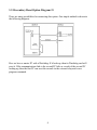
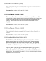
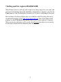
3.2.1Secondary Reset Option Diagram #1
There are many possibilities for connecting this option. One simple method is shown in
the following diagram:
Here we have a master PC with a Watchdog. If it locks up, then its Watchdog card will
reset it. If the communications link to the second PC fails as a result of the second PC
locking up, then the first PC can reset the second via the external relay and a user
program command.
4
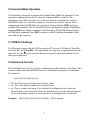
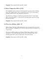
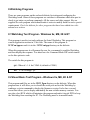
3.2.2Secondary Reset Option Diagram #2
This diagram shows an even more complex example:
Now both PCs have Watchdog cards to reset them if either one locks up. They also talk
to each other through the serial ports and a null MODEM cable. Now either PC can
reset the other if it only partially locks ups.
5
4.Dip Switch Settings
All the switches are read at power up and after each time that the Watchdog resets the
PC. A switch that is DOWN is OFF and a switch that is UP is ON. The following
sections cover the switch options.
4.1Mode Switches - SW1, SW2 & SW3
These three switches set the operating mode of the Watchdog. If all three of these
switches are off then the Watchdog powers up in factory diagnostics mode and will not
operate properly!
It is OK for Ring mode and one more of these switches to be on at one time. The
Watchdog will support Ring mode and one other mode together.
4.1.1Monitor Mode - SW1
When this mode is active the Watchdog will monitor the three output control lines on
the serial COM port of the PC. The lines are:
• Transmit Data (TxD) on Pin 3 of the DB-9.
• Data Terminal Ready (DTR) on Pin 4 of the DB-9.
• Request To Send (RTS) on Pin 7 of the DB-9.
Any activity on any of these lines will cause the Watchdog to reset its timeout count.
4.1.2Command Mode - SW2
If this switch is on the Watchdog enters command mode. This requires that the PC send
commands to the Watchdog as serial data to make it reset the timeout counter. See the
Command Mode section for further information. This mode will require the user to
write support software into their application program.
6
4.1.3Ring Mode - SW3
If this switch is on the Watchdog will count pulses on the Ring Indicator (RI) pin 9 of
the cable from the MODEM. If the number of rings exceed a preset number (set by
switches 6-8) then the Watchdog will reset the PC. If the number of rings is lower,
followed by an idle time of about 15 seconds, then the Watchdog will reset the ring
counter based on the settings of switches 6-8.
If this is the only switch of three that is on then the Watchdog will not use the timeout
mode at all. It will only function as a ring-no-answer Watchdog.
4.2Power On Delay (POD) - SW4
After a power up or a PC reset the Watchdog normally waits 2.5 minutes to allow the
PC to re-boot. This time can be shortened in Command Mode. Sometimes the PC will
require more than 2.5 minutes to complete the re-boot, which can be accommodated by
turning on this switch.
In Monitor or Command Mode the Watchdog will delay starting the timeout counter
until it "sees" the first activity in either of these modes. In the Ring mode it will wait
until the DTR line to MODEM goes active. When DTR goes active the bottom LED
will flash once.
Note: If the PC does not complete the re-boot process correctly, then this option can
disable the Watchdog as well as leave the PC frozen.
4.3Over-temp Reset - SW5
If this switch is on then the Watchdog will reset and hold the reset on a PC during an
over-temp condition. The first trip point is 46°C (115°F) at which point the buzzer will
start to sound. The second trip point where the Watchdog can reset the PC is 56°C
(133°F). If the Watchdog resets the PC, it will remain in reset until the temperature
drops back below 50°C (122°F). A software command allows you to increase these trip
points by adding a fixed offset up to 31°C.
7
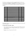
4.4Timeout Count / Ring Count - SW6, SW7, & SW8
These switches set the delay time until the Watchdog resets the PC. As long as the
Watchdog is getting activity in Command or Monitor Mode then it will reset the
timeout counter with these values. These switches also set the ring counts in Ring
Mode for ring-no-answer detection. The settings and times are:
Switches 6-8
OFF-OFF-OFF
OFF-OFF- ON
OFF- ON-OFF
OFF- ON- ON
ON-OFF-OFF
ON-OFF- ON
ON- ON-OFF
ON- ON- ON
Delay Time
5 Seconds
10 Seconds
30 Seconds
1 Minute
10 Minutes
30 Minutes
1 Hour
2 Hour
.
8
Ring Count
2
3
5
9
9
9
9
9
5.Command Mode Operation
The Watchdog is designed to monitor the Transmit Data (TxD) line from the PC and
respond to commands from the PC when the Command Mode is enabled. The
Watchdog is wire-ORed into the receive data line from an external device such as a
MODEM to allow it to send back responses. In a lot of cases the PC may be able to
communicate with a MODEM by activating Data Terminal Ready (DTR) and using
standard AT commands. The PC should be able to communicate with the Watchdog by
dropping DTR and sending commands to the Watchdog. The MODEM should ignore
the Watchdog commands since DTR is inactive and the Watchdog commands do not
start with the AT sequence.
5.1COM Port Settings
The Watchdog requires that the COM port on the PC be set to 1200 Baud, 8 Data Bits,
No Parity Bit, and 2 Stop Bits. The requirement for 2 stop bits is important because the
processor uses the idle time between characters to process input data and take care of
other processing tasks.
5.2Command Formats
The Watchdog looks for a five (5) byte command packet that includes a checksum. This
is done to help insure that MODEM data is not accidentally interpreted as commands.
The format is:
[0x01] [0x57] [0x84] [cc] [ss]
• The first three bytes are always the fixed hex values.
• cc - This is the actual command byte described later.
• ss - This is a simple checksum. It is calculated by adding the prior 4 bytes and
subtracting the value from 0x00. When the Watchdog receives the data and sums all
5 bytes (including checksum) it should get the byte (unsigned char) result 0x00.
Example:
[0x01] [0x57] [0x84] [0x34] [0xF0] - NOP command
9
Example checksum computation using NOP command – 0x34:
0x01 + 0x57 = 0x58
0x58 + 0x84 = 0xDC
0xDC + 0x34 = 0x110 => 0x10 (Checksum is only a byte or unsigned char)
at this point the number required to add to 0x10 is 0xF0 for the checksum byte.
0X10 + 0xF0 = 0x100 => 0x00
Example C code:
int i ;
unsigned char b, strTxBuff[5] = {0x01, 'W', 0x84, 0x00, 0x00} ;
strTxBuff[3] = 0x34 ;
for(i = 0, b = 0; i < 4; i++)
b += strTxBuff[i] ;
strTxBuff[4] = (0 - b) ;
// nop command
// compute checksum
1
5.3Response Format
Important Note:
Any commands that are received OK (except RESET) will cause the Watchdog to
reset the timeout counter.
The response data from the board is a four (4) byte packet that does not have a
checksum. The format is:
[0x57] [0x84] [rr] [0x0d]
• The first two bytes are always the fixed hex values.
• rr - This is the response data byte.
• The last byte is an ASCII Carriage Return [0x0d].
The responses can be one of the following:
•
•
•
•
[0x06] - ACK - Command received and processed OK but no response required.
[0x15] - NAK1 - Command had checksum error.
[0x16] - NAK2 - Invalid command.
[0x20-0xFF] - Responses from commands where required. All responses will have
0x20 (except the temp command – 0x58) added so that they do not look like ASCII
control codes.
1
5.4Watchdog Commands – Revision B Boards
See Section 5.5 for new commands that were added for revision C (and higher)
Internal Serial PC Watchdogs.
The following sections cover the commands that the Watchdog will accept and the
return values if required. This table gives a quick overview of the command numbers.
Command
0x20
0x21
0x24
0x28
0x29
0x30
0x31
0x34
0x38
0x39
0x50
0x51
0x58
Description
Reset PC Now
Reset PC in 10 Seconds
Arm Watchdog Now
Disable Watchdog
Enable Watchdog
Firmware Major Rev
Firmware Minor Rev
No Operation
Get Reset Count
Clear Reset Count & LED
Turn on Relay #2
Turn off Relay #2
Read the Temperature
5.4.1Reset PC Now - [0x20]
This Command will reset the PC within 1 - 2 seconds after the response has been
sent.
Response: None required, will be an ACK - [0x06].
5.4.2Reset PC in 10 Seconds - [0x21]
This Command will reset the PC within 10 - 12 seconds after the response has
been sent.
Response: None required, will be an ACK - [0x06].
1
5.4.3Override Power-On-Delay - [0x24]
This Command will make the Watchdog terminate the 2.5-minute power on delay
and arm itself after a power up or PC reset. If the Power-on-Delay Dip switch is set
(switch number 4) then you will still need to send at least one command (such as
No Operation – 0x34) in order to arm the board. Do not send this command more
than one time!
Response:
0x20 - command processed OK.
0x21 - Watchdog was already armed - command ignored.
5.4.4Disable Watchdog - [0x28]
This Command will disable the Watchdog. USE IT CAREFULLY!
Response: None required, will be an ACK - [0x06].
5.4.5Enable Watchdog - [0x29]
This Command will enable the Watchdog and is used to terminate a Disable
Watchdog command.
Response: None required, will be an ACK - [0x06].
5.4.6Firmware Major Rev - [0x30]
This Command returns the major revision of the firmware.
Response: A value from 0x20 - 0x29. Subtract 0x20 to get the value in hex.
Ex: 0x22 - 0x20 = 2 -> Rev 2.xx
1
5.4.7Firmware Minor Rev - [0x31]
This Command returns the minor revision of the firmware.
Response: A value from 0x20 - 0x83. Subtract 0x20 to get the value in hex.
Ex: 0x43 - 0x20 = 0x23 = 35 -> Rev x.35
5.4.8No Operation - [0x34]
This Command is only used to reset the timeout counter and verify
communications.
Response: None required, will be an ACK - [0x06].
5.4.9Get Reset Count - [0x38]
This Command returns the number of times the Watchdog has reset the PC. The
counter stops at 128 (0x80).
Response: A value from 0x20 - 0xA0. Subtract 0x20 to get the value in hex.
5.4.10Clear Reset Count & LED - [0x39]
This Command clears the reset counter back to zero and turns off the bottom LED.
Response: None required, will be an ACK - [0x06].
5.4.11Turn On Relay #2 - [0x50]
This command turns on the second relay whose contacts are available on the
1/8" Stereo jack above the two LEDs.
Response: None required, will be an ACK - [0x06].
1
5.4.12Turn Off Relay #2 - [0x51]
This command turns off the second relay.
Response: None required, will be an ACK - [0x06].
5.4.13Read the Temperature - [0x58]
This command returns the temperature in degrees Celsius. It can return values
from -32° to +127°C. To accommodate this range the result returned also has an
additional 0x20 added to value. Note: After subtracting the total offset you will
have a signed byte value.
Response: A value from 0x20 - 0xbf. Subtract 0x40 to get the signed value in hex.
Ex: 0x53 - 0x40 = 0x13 = 19°C
Ex: 0x35 - 0x40 = 0xf5 = -11°C
5.4.14Diagnostic Commands - [0xC0-0xCF]
Commands in this range are reserved for diagnostic production tests. They may
produce undesirable results.
1
5.5Watchdog Commands – Revision C Boards
Internal Serial PC Watchdogs that have a PCB Revision of C, or higher, will accept
new commands. Revision C boards will have a firmware version of 2.00 or higher.
Some of these commands allow the user to save configuration data in an on-board nonvolatile memory to override some of the switch settings.
The new Watchdog looks for six (6) byte command packets as well. The format is:
[0x01] [0x57] [0x85] [cc] [vv] [ss]
•
•
•
•
The first three bytes are always the fixed hex values (note the 0x85).
cc - This is the actual command byte described later.
vv – This is a command value such a new delay time.
ss - This is a simple checksum. It is calculated by adding the prior 5 bytes and
subtracting the value from 0x00. When the Watchdog receives the data and sums all
6 bytes (including checksum) it should get the byte (unsigned char) result 0x00.
Example:
[0x01] [0x57] [0x85] [0x60] [0x50] [0x73] - Set Delay Seconds
1
This table gives a quick overview of the new command numbers. This table has two
new sections called: 6 BYTE & NV. If the 6 BYTE value is: YES then it is a 6-byte
command packet. If the NV value is: YES then it is a command that writes or reads the
non-volatile memory. Allow an additional 100mS for the board to respond to these
commands.
Command
0x40
0x41
0x44
0x52
0x53
0x54
0x60
0x61
0x64
0x65
0x68
0x69
0x6C
0x6D
0x70
0x74
0x90-97
0xA0
0xA1
0xA2
0xA3
0xB0-B7
Description
Read DIP Switch MSB
Read DIP Switch LSB
Get Status
Relay #2 ON at Power On
Relay #2 OFF at Power On
Read Relay #2 Status
Set Delay (POD) – Seconds
Set Delay (POD) – Minutes
Save Delay (POD) Seconds
Save Delay (POD) Minutes
Set Timeout – Seconds
Set Timeout – Minutes
Save Timeout Seconds
Save Timeout Minute
Save Reset Relay Pulse Width
Save Temperature Offset
Save User ID Data
Read NV Delay (POD)
Read NV Timeout
Read NV Reset Relay Pulse Width
Read NV Temperature Offset
Read NV User ID Data
6 BYTE
No
No
No
No
No
No
Yes
Yes
Yes
Yes
Yes
Yes
Yes
Yes
Yes
Yes
Yes
No
No
No
No
No
NV
No
No
No
Yes
Yes
Yes
No
No
Yes
Yes
No
No
Yes
Yes
Yes
Yes
Yes
Yes
Yes
Yes
Yes
Yes
The following sections cover the new commands that the Watchdog will accept and the
return values if required.
5.5.1Read DIP Switch MSB - [0x40]
This Command will return the settings of the upper nibble of DIP Switch settings
with 0x20 added. The values will range from 0x20 to 0x2F. A switch that is on
will read as a one (1).
Response: Values will range from 0x20 to 0x2F.
1
5.5.2Read DIP Switch LSB - [0x41]
This Command will return the settings of the lower nibble of DIP Switch settings
with 0x20 added. The values will range from 0x20 to 0x2F. A switch that is on
will read as a one (1).
Response: Values will range from 0x20 to 0x2F.
5.5.3Get Status - [0x44]
This command returns two (2) bits of data in D0 and D1 of the response. There is
also an offset of 0x20 added to the response. The bits are defined as follows:
D0:
D1:
One (1) means that the non-volatile memory was OK at power up.
One (1) means that temperature monitor IC was OK at power up.
Response: Values will range from 0x20 to 0x23.
5.5.4Relay #2 ON at Power On - [0x52]
This Command allows you to set the mode of Relay #2 each time the board powers
up. This relay’s contacts are available on the 1/8" Stereo jack above the two
LEDs. If you send this command the board will store this in non-volatile memory
and turn on the relay each time power is applied to the PC. Use command 0x50
(section 5.4.11) if you want to turn on the relay immediately.
Response: None required, will be an ACK - [0x06].
1
5.5.5Relay #2 OFF at Power On - [0x53]
This Command allows you to set the mode of Relay #2 each time the board powers
up. If you send this command the board will store this in non-volatile memory and
leave the relay off each time power is applied to the PC. Use command 0x51
(section 5.4.12) if you want to turn off the relay immediately.
Response: None required, will be an ACK - [0x06].
5.5.6Read Relay #2 Status - [0x54]
This command returns two (2) bits of data in D0 and D1 of the response. There is
also an offset of 0x20 added to the response. The bits are defined as follows:
D0:
D1:
One (1) means that Relay #2 is currently ON.
One (1) means that Relay #2 is set for ON at power up.
Response: Values will range from 0x20 to 0x23.
5.5.7Set Delay - Seconds - [0x60]
When the board powers up, or after it resets the PC it will normally wait 2.5
minutes (Power-On-Delay - POD) before it arms itself. It may wait a shorter or
longer time if a value has been set in the non-volatile memory using a Save
command. If the board is still in the power on delay mode when it receives this
command then it will set the power on delay to the new value. This enables the
user to shorten or lengthen the current delay.
The value passed in the value byte (vv) allows a range of 0x01 to 0xFF or delays in
the range 0x01 to 0xFF seconds. Note that a value of zero will actually be one
second.
Response:
0x20 - command processed OK.
0x21 - Watchdog was already armed - command ignored.
1
5.5.8Set Delay - Minutes - [0x61]
This works just like the prior command (0x60) except it allows delays to be in
minutes. Note that a value of zero will actually be one minute.
Response:
0x20 - command processed OK.
0x21 - Watchdog was already armed - command ignored.
5.5.9Save Delay - Seconds - [0x64]
This command saves the new value in non-volatile memory for future use. If the
value data (vv) is 0x00, which is a delay of zero, then the non-volatile value will
be cleared and the board will revert back to the 2.5 minute delay at the next re-boot
cycle.
Response:
None required, will be an ACK - [0x06].
5.5.10Save Delay - Minutes - [0x65]
This works just like the prior command (0x60) except it allows delays to be in
minutes.
Response:
None required, will be an ACK - [0x06].
5.5.11Set Timeout - Seconds - [0x68]
When the board starts it will use the DIP switches to get the timeout value or it
may get this value from the non-volatile memory. This command enables the user
to shorten or lengthen the current timeout value.
The value passed in the value byte (vv) should in the range of 0x01 to 0xFF or
timeouts in the range 0x01 to 0xFF seconds. Note that a value of zero will cause
the board to revert to the value in non-volatile memory first if it is present, or the
DIP switch setting.
Response: None required, will be an ACK - [0x06].
2
5.5.12Set Timeout - Minutes - [0x69]
This works just like the prior command (0x68) except it allows timeouts to be in
minutes.
Response: None required, will be an ACK - [0x06].
5.5.13Save Timeout - Seconds - [0x6C]
This command saves the new value in non-volatile memory for future use. If the
value data (vv) is 0x00, which is a delay of zero (0x00), then the non-volatile value
will be cleared and the board will revert back to the timeout setting on the DIP
switches. The new non-volatile time will be used the next time the board is
“tickled”.
Response: None required, will be an ACK - [0x06].
5.5.14Save Timeout - Minutes - [0x6D]
This works just like the prior command (0x6C) except it allows delays to be in
minutes.
Response: None required, will be an ACK - [0x06].
5.5.15Save Reset Relay Pulse Width - [0x70]
The default mode for the Watchdog is to pulse a reset relay (which simulates
pushing the reset button) for 3 seconds. This value works for most computers,
however some machines may require longer or shorter values. This command
allows you to tailor the pulse time by selecting a delay in 50mS tics. This value is
stored in the non-volatile memory.
The value passed in the value byte (vv) should in the range of 0x01 to 0xFF or
pulses in the range 50mS to 12.75 seconds.. A value of zero (0x00) allows you to
return to the default 3-second pulse. The new time will be activated at the next reboot of the PC. Be careful using low times (1 or 2 tics) since these may be too short
to generate valid resets on the PC.
2
Response: None required, will be an ACK - [0x06].
5.5.16Save Temperature Offset - [0x74]
This command permits an increase in the temperature trip points on the watchdog
board. The command allows you to set the offsets up to 31 (0x1f). If the offset is
used then it will be active every time the PC powers up.
The offset here is in degrees C and can range from 0x00 to 0x1F. Values higher
will be corrected modulo 32. A value of zero causes the board to go back to using
the fixed trip values.
Response: None required, will be an ACK - [0x06].
5.5.17Save User ID Data - [0x90 - 97]
Eight (8) bytes of the non-volatile memory have been reserved for the user to store
their own ID data. Commands 0x90 to 0x97 store the user ID bytes in locations 0 to
7 respectively.
These bytes could have many uses with one of them being a software security
mechanism. A user could make their software refuse to run unless there was a
watchdog board in the system with the correct code in the memory.
Response: None required, will be an ACK - [0x06].
2
5.5.18Read NV Delay (POD) - [0xA0]
When you save a Power-On-Delay (POD) in the non-volatile memory the time is
actually stored and used internally as a 16-bit value. In order to read back the value
you will need to issue this command 4 times. Each read will return 4 bits of the
value starting with the MSB. These four bits will have an offset added to them that
will start at 0x20 and increase by 0x10 for each read to keep in sync. If another
command is sent before you complete the 4 reads, then the next time you send this
command it will start over.
Ex: Time saved was 7 minutes = 420 seconds = 0x01A4 saved.
Read #1 = 0x20 | #2 = 0x31 | #3 = 0x4A | #4 = 0x54
Response: Values will range from 0x20 to 0x5F.
5.5.19Read NV Timeout - [0xA1]
This command works just like command 0xA0 described in the prior section
except it returns the watchdog timeout value.
Response: Values will range from 0x20 to 0x5F.
5.5.20Read NV Reset Relay Pulse Width - [0xA2]
When you save a reset relay pulse width in the non-volatile memory the time is
stored as an 8-bit value This command works just like command 0xA0 described
in the prior section except it returns only 2 nibbles (4 bits each) of data.
Response: Values will range from 0x20 to 0x3F.
5.5.21Read NV Temperature Offset - [0xA3]
This command works just like command 0xA2 described in the prior section
except it returns the temperature offset value.
Response: Values will range from 0x20 to 0x3F.
2
5.5.22Read NV User ID Data - [0xB0 - B7]
This command works just like command 0xA2 described in the prior section
except it returns the user ID data bytes. Commands 0xB0 to 0xB7 return the user
ID bytes in locations 0 to 7 respectively.
Response: Values will range from 0x20 to 0x3F.
2
6.LED Operation
The two LEDs on the Watchdog are used for system status.
6.1Top LED
During the 2.5 minutes that the Watchdog waits after power-up or after it resets the PC
it will flash this LED at a 1 second rate (1 second on, 1 second off). Once the Watchdog
has armed itself it will flash the LED at a 350mS rate. In the last 3 seconds before the
Watchdog resets the PC it will flash this LED rapidly at a 100mS rate.
6.2Bottom LED
After the first time the Watchdog resets the PC it will light this LED as a visible
indicator that at least one reset (maybe more) has occurred. This LED can be turned off
by cycling power on the Watchdog, pushing the PC reset button, or via Command
Mode.
This LED will also flash once per second for 100mS to indicate that activity has been
detected in Command or Monitor Mode and for each ring pulse from the MODEM in
Ring Mode. This flash will be the inverse of the LED state at the time.
2
7.Getting past the Login on Win95/98 & ME
When Windows boots it will stop with a login screen that prompts for a user name and
password. It will hang at this point indefinitely until the data is entered or you click the
Cancel button. If the Watchdog has rebooted your PC then it would hang at this point.
Microsoft has solved this problem with a set of utilities called Powertoys that can be
downloaded from their site at: http://www.microsoft.com/. One of the utilities in the
package is called TWEAKUI that installs in the Control Panel under My Computer.
When you run the utility there will be a tab called Network that allows you to specify
an auto login and provide the computer name and password.
2
8.Watchdog Programs
There are some programs on the enclosed diskette for testing and configuring the
Watchdog board. Some of these programs use switches to determine which user port to
check to get status or perform commands. All the source and other support files are
supplied for each program which should make it easier to modify them for user's special
requirements. Check the diskette for other programs that have been added since this
manual was written.
8.1Watchdog Test Program - Windows 9x, ME, 2K & NT
This program is used to test and configure the Serial Watchdog. This program is a
console application written in 32 bit code. The name of this program is:
W32ConApp.exe and it is in the \ W32ConApp directory on the diskette.
When this program runs it will prompt the user for a command to send the Watchdog
and then display the response. You must have the Command Mode DIP switch turned
on for this option to work.
The switch for this program is:
/p# - Where # = 1-4 for COM1-4 (default is COM1)
EX: C:>w32conapp /p2
8.2Visual Basic Test Program - Windows 9x, ME, 2K & NT
This program and files are in the VB32_Pgm directory on the diskette. When this
program runs it will allow you to choose the serial port and test the Watchdog by
sending a revision command to display the firmware version. It also has a second
screen that allows you to display and modify the non-volatile memory contents. You
can also select RUN which will minimize the program and make it toggle DTR to keep
the Watchdog from resetting the PC. The Watchdog must be in monitor mode.
2
You can put this program into a startup group with two command line switches that
must be present. The switches for this program are:
/p# - Where # = 1-4 for COM1-4 (default is COM1)
/m - start minimized
EX: Ser-WDog /p2 /m
2
9.Appendix A - Specifications
Power Requirements:
+5 VDC - 200mA Max.
Environmental:
-20 - 65°C Operating
-20 - 70°C Storage
5-95% Relative Humidity - Non Condensing
MTBF:
500,000 Hours
TEMP:
± 1.5°C
Note: You may find that the board will continue to work just fine beyond the
specified temperature limits, especially at lower temperatures. These temperature
limits are those specified by the manufacturers of the integrated circuits.
Relay #2:
SPST (1 form a) - 48V @ 0.5A max
This relay has contacts that are available on the 1/8" Stereo jack above the two
LEDs. The tip of the plug is one relay contact and the ring (second terminal on the
plug) is the other relay contact. The major or last conductor (sleeve) of the plug is
ground and is connected to the PC bracket.
2
10.Appendix B - Warranty
Berkshire Products, Inc. warrants to the original consumer or other end user purchaser
that this product is free from defects in materials or workmanship for a period of one
(1) year from the date of purchase. During the warranty period, and upon proof of
purchase, the product will be repaired or replaced (with the same or functionally
equivalent model) at our option, without charge for either parts or labor.
This warranty does not apply to defects due directly or indirectly to misuse, abuse,
negligence, accident, repairs or alterations made by the customer or another party.
UNDER NO CIRCUMSTANCES WILL BERKSHIRE PRODUCTS, Inc. BE LIABLE
IN ANY WAY TO ANY PURCHASER FOR DAMAGES, LOST REVENUE, LOST
WAGES, OR ANY OTHER INCIDENTAL OR CONSEQUENTIAL DAMAGES
ARISING OUT OF THE USE OR INABILITY TO USE THIS PRODUCT.
Berkshire Products, Inc. reserves the right to make modifications in this product
without prior notification.
3
11.Appendix C - Service and Tech Support
We are available to help you with your questions and problems that you may have with
our product. Our technical support is available:
Monday through Friday (except holidays)
8:30 AM to 5:00 PM (Eastern Time)
770-271-0088
Email: [email protected]
11.1Calling Tech Support
To help our tech support personnel with your problem, please try to have the following
information ready:
• Type of PC
• Type of operating system and version
• Clear description of the problem
11.2Product Returns
Please call our tech support personnel before returning a product. Many times the
problem can be corrected over the phone. If the tech support representative determines
that your product must be returned, they will assign you a RMA #.
Package the product in a secure container and return it to us freight prepaid. We will
not accept COD freight charges! Indicate the RMA # on the package or shipping label.
If the repairs are done under warranty the unit will be returned UPS ground and we will
pay the freight charges. If you prefer Federal Express, please provide your Federal
Express account number.
If your unit is out of warranty, repairs and shipping will be charged COD or other
method established in advance.
3
12.Appendix D - Agency Approvals
The PC Watchdog meets the following agency approvals.
12.1FCC - Class A
This equipment generates and uses radio frequency energy and if not installed and used
properly, that is in strict adherence with the manufacturer’s instructions, may cause
interference to radio and television reception. It has been tested and found to comply
with the limits for a Class A computing device in accordance with the specifications in
Subpart J of Part 15 of FCC rules, which are designed to provide reasonable protection
against such interference in a commercial installation. If this equipment does cause
interference to radio or television reception, which can be determined by turning the
equipment off and on, the user is encouraged to try to correct the interference by one or
more of the following measures:
•
•
•
•
Reorient the receiving antenna.
Relocate the computer with respect to the receiver.
Move the computer away from the receiver.
Plug the computer into a different outlet so that the computer and receiver are on
different branch circuits.
• Consult the dealer or an experienced radio/TV technician for help.
12.2CE
The Internal Serial PC Watchdog has successfully passed all appropriate tests that are
necessary for its certification under EMC directive 89/336/EEC.
3