1
Agilent 4294A Precision Impedance Analyzer
Programming Manual
Eighth Edition
FIRMWARE REVISIONS
This manual applies directly to instruments that have the firmware revision 1.11.
For additional information about firmware revisions, see Appendix A.
Part No. 04294-90061
August 2012
Printed in Japan
Notices
The information contained in this document is subject to change without notice.
This document contains proprietary information that is protected by copyright. All
rights are reserved. No part of this document may be photocopied, reproduced, or
translated to another language without the prior written consent of Agilent
Technologies.
Agilent Technologies Japan, Ltd.
Kobe Instrument Division
1-3-2, Murotani, Nishi-Ku, Kobe-shi, Hyogo, 651-2241 Japan
MS-DOS, Windows, Windows 95, Windows NT, Visual C++, Visual Basic and
Excel are U.S. registered trademarks of Microsoft Corporation.
UNIX is a registered trademark in the United States and other countries, licensed
exclusively through X/Open Company Limited.
Copyright © 1999, 2000, 2002, 2003, 2012 Agilent Technologies Japan, Ltd.
Manual Printing History
The manual’s printing date and part number indicate its current edition. The
printing date changes when a new edition is printed. (Minor corrections and
updates incorporated in reprints do not necessitate a new printing date.) The
manual part number changes when extensive technical changes are incorporated.
April 1999
First Edition (Agilent P/N: 04294-90001)
June 1999
Second Edition (Agilent P/N: 04294-90011)
December 1999
Third Edition (Agilent P/N: 04294-90021)
May 2000
Fourth Edition (Agilent P/N: 04294-90031)
May 2002
Fifth Edition (Agilent P/N: 04294-90041)
November 2002 Sixth Edition (Agilent P/N: 04294-90051)
June 2003
Seventh Edition (Agilent P/N: 04294-90061)
August 2012
Eighth Edition (Agilent P/N: 04294-90061)
2
Sample Program Disk
A sample program disk (Agilent Part Number 04294-18020) is supplied with this
manual. The disk contains the sample programs listed in this manual.
The customer shall have the personal, nontransferable rights to use, copy, or
modify SAMPLE PROGRAMS in this manual for the Customer’s internal
operations. The customer shall use the SAMPLE PROGRAMS solely and
exclusively for their own purpose and shall not license, lease, market, or distribute
the SAMPLE PROGRAMS or modifications of any part thereof.
Agilent Technologies shall not be liable for the quality, performance, or behavior
of the SAMPLE PROGRAMS. Agilent Technologies especially disclaims that the
operation of the SAMPLE PROGRAMS shall be uninterrupted or error free. The
SAMPLE PROGRAMS are provided AS IS.
AGILENT TECHNOLOGIES DISCLAIMS IMPLIED WARRANTIES OF
MERCHANTABILITY AND FITNESS FOR A PARTICULAR PURPOSE.
Agilent Technologies shall not be liable for any infringement of any patent,
trademark, copyright, or other proprietary rights by the SAMPLE PROGRAMS or
their use. Agilent Technologies does not warrant that the SAMPLE PROGRAMS
are free from infringements of such rights of third parties. However, Agilent
Technologies will not knowingly infringe or deliver software that infringes the
patent, trademark, copyright, or other proprietary right of a third party.
3
4
Contents
1. To make effective use of this manual
Contents of this manual . . . . . . . . . . . . . . . . . . . . . . . . . . . . . . . . . . . . . . . . . . . . . . . . . . . . . . . . . . . . . . . . 20
How To Use This Manual . . . . . . . . . . . . . . . . . . . . . . . . . . . . . . . . . . . . . . . . . . . . . . . . . . . . . . . . . . . . . . . 22
Sample programs. . . . . . . . . . . . . . . . . . . . . . . . . . . . . . . . . . . . . . . . . . . . . . . . . . . . . . . . . . . . . . . . . . . . 22
Other manuals attached to this unit. . . . . . . . . . . . . . . . . . . . . . . . . . . . . . . . . . . . . . . . . . . . . . . . . . . . . . . . 23
Operation Manual (part number: 04294-900x0) . . . . . . . . . . . . . . . . . . . . . . . . . . . . . . . . . . . . . . . . . . . . 23
HP Instrument BASIC User’s Handbook (part number: E2083-90005). . . . . . . . . . . . . . . . . . . . . . . . . . 23
Service Manual (option 0BW only) (part number: 04294-901x0) . . . . . . . . . . . . . . . . . . . . . . . . . . . . . . 23
2. Remote Control, Overview
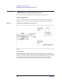
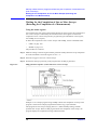
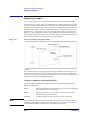
GPIB Remote Control System, Overview . . . . . . . . . . . . . . . . . . . . . . . . . . . . . . . . . . . . . . . . . . . . . . . . . . 26
System configuration. . . . . . . . . . . . . . . . . . . . . . . . . . . . . . . . . . . . . . . . . . . . . . . . . . . . . . . . . . . . . . . . . 26
Controller . . . . . . . . . . . . . . . . . . . . . . . . . . . . . . . . . . . . . . . . . . . . . . . . . . . . . . . . . . . . . . . . . . . . . . . . . 28
Device selector . . . . . . . . . . . . . . . . . . . . . . . . . . . . . . . . . . . . . . . . . . . . . . . . . . . . . . . . . . . . . . . . . . . . . 28
Sending GPIB Command Messages . . . . . . . . . . . . . . . . . . . . . . . . . . . . . . . . . . . . . . . . . . . . . . . . . . . . . . . 29
GPIB commands . . . . . . . . . . . . . . . . . . . . . . . . . . . . . . . . . . . . . . . . . . . . . . . . . . . . . . . . . . . . . . . . . . . . 29
Message syntax . . . . . . . . . . . . . . . . . . . . . . . . . . . . . . . . . . . . . . . . . . . . . . . . . . . . . . . . . . . . . . . . . . . . . 29
The Basics of Writing/Running Programs . . . . . . . . . . . . . . . . . . . . . . . . . . . . . . . . . . . . . . . . . . . . . . . . . . 30
An easy way to write a program . . . . . . . . . . . . . . . . . . . . . . . . . . . . . . . . . . . . . . . . . . . . . . . . . . . . . . . . 30
Running the program. . . . . . . . . . . . . . . . . . . . . . . . . . . . . . . . . . . . . . . . . . . . . . . . . . . . . . . . . . . . . . . . . 32
Saving and Reading the Program . . . . . . . . . . . . . . . . . . . . . . . . . . . . . . . . . . . . . . . . . . . . . . . . . . . . . . . . . 33
Saving the program generated. . . . . . . . . . . . . . . . . . . . . . . . . . . . . . . . . . . . . . . . . . . . . . . . . . . . . . . . . . 33
Reading the saved file . . . . . . . . . . . . . . . . . . . . . . . . . . . . . . . . . . . . . . . . . . . . . . . . . . . . . . . . . . . . . . . . 33
Remote Control using a LAN . . . . . . . . . . . . . . . . . . . . . . . . . . . . . . . . . . . . . . . . . . . . . . . . . . . . . . . . . . . . 34
3. Setting Measurement Conditions
Setting Measurement Parameters . . . . . . . . . . . . . . . . . . . . . . . . . . . . . . . . . . . . . . . . . . . . . . . . . . . . . . . . . 36
Setting Measurement Signals . . . . . . . . . . . . . . . . . . . . . . . . . . . . . . . . . . . . . . . . . . . . . . . . . . . . . . . . . . . . 38
Setting the oscillator . . . . . . . . . . . . . . . . . . . . . . . . . . . . . . . . . . . . . . . . . . . . . . . . . . . . . . . . . . . . . . . . . 38
Setting a dc bias. . . . . . . . . . . . . . . . . . . . . . . . . . . . . . . . . . . . . . . . . . . . . . . . . . . . . . . . . . . . . . . . . . . . . 38
Setting a Sweep Condition . . . . . . . . . . . . . . . . . . . . . . . . . . . . . . . . . . . . . . . . . . . . . . . . . . . . . . . . . . . . . . 39
Setting a sweep parameter. . . . . . . . . . . . . . . . . . . . . . . . . . . . . . . . . . . . . . . . . . . . . . . . . . . . . . . . . . . . . 39
Setting a sweep range . . . . . . . . . . . . . . . . . . . . . . . . . . . . . . . . . . . . . . . . . . . . . . . . . . . . . . . . . . . . . . . . 39
Setting sweep time . . . . . . . . . . . . . . . . . . . . . . . . . . . . . . . . . . . . . . . . . . . . . . . . . . . . . . . . . . . . . . . . . . 39
Setting a sweep direction. . . . . . . . . . . . . . . . . . . . . . . . . . . . . . . . . . . . . . . . . . . . . . . . . . . . . . . . . . . . . . 39
Setting a sweep type . . . . . . . . . . . . . . . . . . . . . . . . . . . . . . . . . . . . . . . . . . . . . . . . . . . . . . . . . . . . . . . . . 39
Setting the On-screen Arrangement . . . . . . . . . . . . . . . . . . . . . . . . . . . . . . . . . . . . . . . . . . . . . . . . . . . . . . . 40
Setting how the way traces are displayed . . . . . . . . . . . . . . . . . . . . . . . . . . . . . . . . . . . . . . . . . . . . . . . . . 40
Setting a display scale . . . . . . . . . . . . . . . . . . . . . . . . . . . . . . . . . . . . . . . . . . . . . . . . . . . . . . . . . . . . . . . . 41
Setting Averaging . . . . . . . . . . . . . . . . . . . . . . . . . . . . . . . . . . . . . . . . . . . . . . . . . . . . . . . . . . . . . . . . . . . . . 43
Setting a measurement bandwidth. . . . . . . . . . . . . . . . . . . . . . . . . . . . . . . . . . . . . . . . . . . . . . . . . . . . . . . 43
Setting averaging. . . . . . . . . . . . . . . . . . . . . . . . . . . . . . . . . . . . . . . . . . . . . . . . . . . . . . . . . . . . . . . . . . . . 43
Combining Two or More Sweep Conditions (List Sweep). . . . . . . . . . . . . . . . . . . . . . . . . . . . . . . . . . . . . . 44
Making/editing a segment . . . . . . . . . . . . . . . . . . . . . . . . . . . . . . . . . . . . . . . . . . . . . . . . . . . . . . . . . . . . . 44
Deleting a segment . . . . . . . . . . . . . . . . . . . . . . . . . . . . . . . . . . . . . . . . . . . . . . . . . . . . . . . . . . . . . . . . . . 45
Setting the trace color of each segment. . . . . . . . . . . . . . . . . . . . . . . . . . . . . . . . . . . . . . . . . . . . . . . . . . . 45
Setting the Limit Test Functions . . . . . . . . . . . . . . . . . . . . . . . . . . . . . . . . . . . . . . . . . . . . . . . . . . . . . . . . . . 46
Making/editing a segment . . . . . . . . . . . . . . . . . . . . . . . . . . . . . . . . . . . . . . . . . . . . . . . . . . . . . . . . . . . . . 46
5
Contents
Deleting a segment . . . . . . . . . . . . . . . . . . . . . . . . . . . . . . . . . . . . . . . . . . . . . . . . . . . . . . . . . . . . . . . . . .
Moving offset ranges . . . . . . . . . . . . . . . . . . . . . . . . . . . . . . . . . . . . . . . . . . . . . . . . . . . . . . . . . . . . . . . .
Saving/Recalling Measurement Conditions . . . . . . . . . . . . . . . . . . . . . . . . . . . . . . . . . . . . . . . . . . . . . . . . .
A Sample Program for Setting Measurement Conditions . . . . . . . . . . . . . . . . . . . . . . . . . . . . . . . . . . . . . .
47
47
48
49
4. Preparing For Accurate Measurement
Adapter Setting. . . . . . . . . . . . . . . . . . . . . . . . . . . . . . . . . . . . . . . . . . . . . . . . . . . . . . . . . . . . . . . . . . . . . . .
User Calibration . . . . . . . . . . . . . . . . . . . . . . . . . . . . . . . . . . . . . . . . . . . . . . . . . . . . . . . . . . . . . . . . . . . . . .
Fixture Compensation . . . . . . . . . . . . . . . . . . . . . . . . . . . . . . . . . . . . . . . . . . . . . . . . . . . . . . . . . . . . . . . . .
Port Extension Compensation . . . . . . . . . . . . . . . . . . . . . . . . . . . . . . . . . . . . . . . . . . . . . . . . . . . . . . . . . . .
54
58
63
70
5. Starting a Measurement (Trigger) and Detecting the Completion of a Measurement (End of Sweeps)
Triggering a Measurement (Starting a Measurement) . . . . . . . . . . . . . . . . . . . . . . . . . . . . . . . . . . . . . . . . .
Trigger system. . . . . . . . . . . . . . . . . . . . . . . . . . . . . . . . . . . . . . . . . . . . . . . . . . . . . . . . . . . . . . . . . . . . . .
Triggering a measurement . . . . . . . . . . . . . . . . . . . . . . . . . . . . . . . . . . . . . . . . . . . . . . . . . . . . . . . . . . . .
Waiting for the Completion of One or More Sweeps (Detecting the Completion of a Measurement) . . . .
Using the status register . . . . . . . . . . . . . . . . . . . . . . . . . . . . . . . . . . . . . . . . . . . . . . . . . . . . . . . . . . . . . .
Using the *OPC? command . . . . . . . . . . . . . . . . . . . . . . . . . . . . . . . . . . . . . . . . . . . . . . . . . . . . . . . . . . .
Inserting a wait . . . . . . . . . . . . . . . . . . . . . . . . . . . . . . . . . . . . . . . . . . . . . . . . . . . . . . . . . . . . . . . . . . . . .
72
72
73
74
74
76
76
6. Reading/Writing Measurement Data
Data Transfer Format . . . . . . . . . . . . . . . . . . . . . . . . . . . . . . . . . . . . . . . . . . . . . . . . . . . . . . . . . . . . . . . . . .
ASCII format (Form 4) . . . . . . . . . . . . . . . . . . . . . . . . . . . . . . . . . . . . . . . . . . . . . . . . . . . . . . . . . . . . . . .
IEEE 32-bit floating point format (Form 2) . . . . . . . . . . . . . . . . . . . . . . . . . . . . . . . . . . . . . . . . . . . . . . .
IEEE 64-bit floating point format (Form 3) . . . . . . . . . . . . . . . . . . . . . . . . . . . . . . . . . . . . . . . . . . . . . . .
MS-DOS personal computer format (Form 5) . . . . . . . . . . . . . . . . . . . . . . . . . . . . . . . . . . . . . . . . . . . . .
Internal Data Processing. . . . . . . . . . . . . . . . . . . . . . . . . . . . . . . . . . . . . . . . . . . . . . . . . . . . . . . . . . . . . . . .
Data processing sequence . . . . . . . . . . . . . . . . . . . . . . . . . . . . . . . . . . . . . . . . . . . . . . . . . . . . . . . . . . . . .
Internal data arrays . . . . . . . . . . . . . . . . . . . . . . . . . . . . . . . . . . . . . . . . . . . . . . . . . . . . . . . . . . . . . . . . . .
Reading/Writing Data. . . . . . . . . . . . . . . . . . . . . . . . . . . . . . . . . . . . . . . . . . . . . . . . . . . . . . . . . . . . . . . . . .
Reading/writing measurement data . . . . . . . . . . . . . . . . . . . . . . . . . . . . . . . . . . . . . . . . . . . . . . . . . . . . .
Reading level monitoring results . . . . . . . . . . . . . . . . . . . . . . . . . . . . . . . . . . . . . . . . . . . . . . . . . . . . . . .
Reading limit test results. . . . . . . . . . . . . . . . . . . . . . . . . . . . . . . . . . . . . . . . . . . . . . . . . . . . . . . . . . . . . .
When to read/write data . . . . . . . . . . . . . . . . . . . . . . . . . . . . . . . . . . . . . . . . . . . . . . . . . . . . . . . . . . . . . .
78
78
79
80
80
81
81
81
84
84
87
89
93
7. Processing Measurement Results
Reading Measurement Data at Specific Measurement Points (Using the Marker Function). . . . . . . . . . . . 96
Moving the marker . . . . . . . . . . . . . . . . . . . . . . . . . . . . . . . . . . . . . . . . . . . . . . . . . . . . . . . . . . . . . . . . . . 96
Reading the marker-specified value . . . . . . . . . . . . . . . . . . . . . . . . . . . . . . . . . . . . . . . . . . . . . . . . . . . . . 98
Sample program for using the marker function . . . . . . . . . . . . . . . . . . . . . . . . . . . . . . . . . . . . . . . . . . . . 98
Analyzing Measurement Results . . . . . . . . . . . . . . . . . . . . . . . . . . . . . . . . . . . . . . . . . . . . . . . . . . . . . . . . 100
Equivalent circuit analysis . . . . . . . . . . . . . . . . . . . . . . . . . . . . . . . . . . . . . . . . . . . . . . . . . . . . . . . . . . . 100
Statistics analysis . . . . . . . . . . . . . . . . . . . . . . . . . . . . . . . . . . . . . . . . . . . . . . . . . . . . . . . . . . . . . . . . . . 102
Bandwidth analysis . . . . . . . . . . . . . . . . . . . . . . . . . . . . . . . . . . . . . . . . . . . . . . . . . . . . . . . . . . . . . . . . . 103
Various analysis methods available with waveform analysis commands. . . . . . . . . . . . . . . . . . . . . . . . 106
8. Saving/Recalling a Measurement Result/Measurement Setup
Save/Recall of a File. . . . . . . . . . . . . . . . . . . . . . . . . . . . . . . . . . . . . . . . . . . . . . . . . . . . . . . . . . . . . . . . . . 112
6
Contents
Specifying a location for save/recall . . . . . . . . . . . . . . . . . . . . . . . . . . . . . . . . . . . . . . . . . . . . . . . . . . . .
Saving data into a file . . . . . . . . . . . . . . . . . . . . . . . . . . . . . . . . . . . . . . . . . . . . . . . . . . . . . . . . . . . . . . .
Recalling a file . . . . . . . . . . . . . . . . . . . . . . . . . . . . . . . . . . . . . . . . . . . . . . . . . . . . . . . . . . . . . . . . . . . .
Copying/deleting a file . . . . . . . . . . . . . . . . . . . . . . . . . . . . . . . . . . . . . . . . . . . . . . . . . . . . . . . . . . . . . .
Creating a directory. . . . . . . . . . . . . . . . . . . . . . . . . . . . . . . . . . . . . . . . . . . . . . . . . . . . . . . . . . . . . . . . .
Sample Program for Save/Recall . . . . . . . . . . . . . . . . . . . . . . . . . . . . . . . . . . . . . . . . . . . . . . . . . . . . . . . .
112
112
113
114
114
115
9. Communication with External Equipment (Using the I/O Ports)
Using the I/O Ports . . . . . . . . . . . . . . . . . . . . . . . . . . . . . . . . . . . . . . . . . . . . . . . . . . . . . . . . . . . . . . . . . . . 120
8-bit I/O port . . . . . . . . . . . . . . . . . . . . . . . . . . . . . . . . . . . . . . . . . . . . . . . . . . . . . . . . . . . . . . . . . . . . . . 120
24-bit I/O port . . . . . . . . . . . . . . . . . . . . . . . . . . . . . . . . . . . . . . . . . . . . . . . . . . . . . . . . . . . . . . . . . . . . . 122
Sample Program to Use the I/O Port . . . . . . . . . . . . . . . . . . . . . . . . . . . . . . . . . . . . . . . . . . . . . . . . . . . . . 129
10. Handling Errors
Using the Status Register . . . . . . . . . . . . . . . . . . . . . . . . . . . . . . . . . . . . . . . . . . . . . . . . . . . . . . . . . . . . . . 132
Using the Error Queue . . . . . . . . . . . . . . . . . . . . . . . . . . . . . . . . . . . . . . . . . . . . . . . . . . . . . . . . . . . . . . . . 133
Sample program for error handling . . . . . . . . . . . . . . . . . . . . . . . . . . . . . . . . . . . . . . . . . . . . . . . . . . . . . . 134
11. Using HP Instrument BASIC
HP Instrument BASIC, Overview . . . . . . . . . . . . . . . . . . . . . . . . . . . . . . . . . . . . . . . . . . . . . . . . . . . . . . . 138
Controlling the Agilent 4294A . . . . . . . . . . . . . . . . . . . . . . . . . . . . . . . . . . . . . . . . . . . . . . . . . . . . . . . . . . 138
Reserving an Area for BASIC on the Screen . . . . . . . . . . . . . . . . . . . . . . . . . . . . . . . . . . . . . . . . . . . . . . . 139
Entering BASIC Commands Using the Keys Located on the Front Panel. . . . . . . . . . . . . . . . . . . . . . . . . 139
Editing a Program . . . . . . . . . . . . . . . . . . . . . . . . . . . . . . . . . . . . . . . . . . . . . . . . . . . . . . . . . . . . . . . . . . . . 140
Starting up and exiting edit mode . . . . . . . . . . . . . . . . . . . . . . . . . . . . . . . . . . . . . . . . . . . . . . . . . . . . . . 140
Editing a program . . . . . . . . . . . . . . . . . . . . . . . . . . . . . . . . . . . . . . . . . . . . . . . . . . . . . . . . . . . . . . . . . . 140
Re-numbering a line number. . . . . . . . . . . . . . . . . . . . . . . . . . . . . . . . . . . . . . . . . . . . . . . . . . . . . . . . . . 142
Running a Program . . . . . . . . . . . . . . . . . . . . . . . . . . . . . . . . . . . . . . . . . . . . . . . . . . . . . . . . . . . . . . . . . . . 143
Running a program through the softkey interface. . . . . . . . . . . . . . . . . . . . . . . . . . . . . . . . . . . . . . . . . . 143
Automatically starting a program at power-on . . . . . . . . . . . . . . . . . . . . . . . . . . . . . . . . . . . . . . . . . . . . 143
Listing a Program (LIST) . . . . . . . . . . . . . . . . . . . . . . . . . . . . . . . . . . . . . . . . . . . . . . . . . . . . . . . . . . . . . . 144
Displaying a program listing on the screen . . . . . . . . . . . . . . . . . . . . . . . . . . . . . . . . . . . . . . . . . . . . . . . 144
Outputting a program listing to the printer . . . . . . . . . . . . . . . . . . . . . . . . . . . . . . . . . . . . . . . . . . . . . . . 144
Saving a Program (SAVE) . . . . . . . . . . . . . . . . . . . . . . . . . . . . . . . . . . . . . . . . . . . . . . . . . . . . . . . . . . . . . 145
Listing File Names (CAT). . . . . . . . . . . . . . . . . . . . . . . . . . . . . . . . . . . . . . . . . . . . . . . . . . . . . . . . . . . . . . 146
Displaying a list of file names on the screen. . . . . . . . . . . . . . . . . . . . . . . . . . . . . . . . . . . . . . . . . . . . . . 146
Outputting a list of file names to the printer . . . . . . . . . . . . . . . . . . . . . . . . . . . . . . . . . . . . . . . . . . . . . . 146
Reading a Program (GET) . . . . . . . . . . . . . . . . . . . . . . . . . . . . . . . . . . . . . . . . . . . . . . . . . . . . . . . . . . . . . 147
ON KEY LABEL Functions. . . . . . . . . . . . . . . . . . . . . . . . . . . . . . . . . . . . . . . . . . . . . . . . . . . . . . . . . . . . 148
Pass Control Involved with an External Controller . . . . . . . . . . . . . . . . . . . . . . . . . . . . . . . . . . . . . . . . . . 149
Pass control . . . . . . . . . . . . . . . . . . . . . . . . . . . . . . . . . . . . . . . . . . . . . . . . . . . . . . . . . . . . . . . . . . . . . . . 149
Communicating with an external controller . . . . . . . . . . . . . . . . . . . . . . . . . . . . . . . . . . . . . . . . . . . . . . 150
Usable I/O Interfaces and Select Code . . . . . . . . . . . . . . . . . . . . . . . . . . . . . . . . . . . . . . . . . . . . . . . . . . . . 151
External RUN/CONTinue Connector . . . . . . . . . . . . . . . . . . . . . . . . . . . . . . . . . . . . . . . . . . . . . . . . . . . . . 151
Displaying Graphics . . . . . . . . . . . . . . . . . . . . . . . . . . . . . . . . . . . . . . . . . . . . . . . . . . . . . . . . . . . . . . . . . . 152
Graphics commands of Instrument BASIC. . . . . . . . . . . . . . . . . . . . . . . . . . . . . . . . . . . . . . . . . . . . . . . 152
Hard copy . . . . . . . . . . . . . . . . . . . . . . . . . . . . . . . . . . . . . . . . . . . . . . . . . . . . . . . . . . . . . . . . . . . . . . . . 153
Default setting . . . . . . . . . . . . . . . . . . . . . . . . . . . . . . . . . . . . . . . . . . . . . . . . . . . . . . . . . . . . . . . . . . . . . 153
7
Contents
A sample graphics program . . . . . . . . . . . . . . . . . . . . . . . . . . . . . . . . . . . . . . . . . . . . . . . . . . . . . . . . . .
Keyboard . . . . . . . . . . . . . . . . . . . . . . . . . . . . . . . . . . . . . . . . . . . . . . . . . . . . . . . . . . . . . . . . . . . . . . . . . .
Character entry keys . . . . . . . . . . . . . . . . . . . . . . . . . . . . . . . . . . . . . . . . . . . . . . . . . . . . . . . . . . . . . . . .
Cursor control and display control . . . . . . . . . . . . . . . . . . . . . . . . . . . . . . . . . . . . . . . . . . . . . . . . . . . . .
Numeric keys . . . . . . . . . . . . . . . . . . . . . . . . . . . . . . . . . . . . . . . . . . . . . . . . . . . . . . . . . . . . . . . . . . . . .
Edit keys . . . . . . . . . . . . . . . . . . . . . . . . . . . . . . . . . . . . . . . . . . . . . . . . . . . . . . . . . . . . . . . . . . . . . . . . .
Program control keys . . . . . . . . . . . . . . . . . . . . . . . . . . . . . . . . . . . . . . . . . . . . . . . . . . . . . . . . . . . . . . .
System control keys . . . . . . . . . . . . . . . . . . . . . . . . . . . . . . . . . . . . . . . . . . . . . . . . . . . . . . . . . . . . . . . .
Softkeys . . . . . . . . . . . . . . . . . . . . . . . . . . . . . . . . . . . . . . . . . . . . . . . . . . . . . . . . . . . . . . . . . . . . . . . . .
Soft control keys . . . . . . . . . . . . . . . . . . . . . . . . . . . . . . . . . . . . . . . . . . . . . . . . . . . . . . . . . . . . . . . . . . .
Softkeys accessed from [Shift]+[F9] key.. . . . . . . . . . . . . . . . . . . . . . . . . . . . . . . . . . . . . . . . . . . . . . . .
The [Ctrl] in edit mode . . . . . . . . . . . . . . . . . . . . . . . . . . . . . . . . . . . . . . . . . . . . . . . . . . . . . . . . . . . . . .
Displaying program execution status . . . . . . . . . . . . . . . . . . . . . . . . . . . . . . . . . . . . . . . . . . . . . . . . . . .
Instrument BASIC Commands Specific to the Agilent 4294A . . . . . . . . . . . . . . . . . . . . . . . . . . . . . . . . .
DATE . . . . . . . . . . . . . . . . . . . . . . . . . . . . . . . . . . . . . . . . . . . . . . . . . . . . . . . . . . . . . . . . . . . . . . . . . . .
DATE$ . . . . . . . . . . . . . . . . . . . . . . . . . . . . . . . . . . . . . . . . . . . . . . . . . . . . . . . . . . . . . . . . . . . . . . . . . .
READIO . . . . . . . . . . . . . . . . . . . . . . . . . . . . . . . . . . . . . . . . . . . . . . . . . . . . . . . . . . . . . . . . . . . . . . . . .
SET TIME. . . . . . . . . . . . . . . . . . . . . . . . . . . . . . . . . . . . . . . . . . . . . . . . . . . . . . . . . . . . . . . . . . . . . . . .
SET TIMEDATE . . . . . . . . . . . . . . . . . . . . . . . . . . . . . . . . . . . . . . . . . . . . . . . . . . . . . . . . . . . . . . . . . .
TIME. . . . . . . . . . . . . . . . . . . . . . . . . . . . . . . . . . . . . . . . . . . . . . . . . . . . . . . . . . . . . . . . . . . . . . . . . . . .
TIME$. . . . . . . . . . . . . . . . . . . . . . . . . . . . . . . . . . . . . . . . . . . . . . . . . . . . . . . . . . . . . . . . . . . . . . . . . . .
WRITEIO . . . . . . . . . . . . . . . . . . . . . . . . . . . . . . . . . . . . . . . . . . . . . . . . . . . . . . . . . . . . . . . . . . . . . . . .
Instrument BASIC Commands that Cannot be Run on the Agilent 4294A . . . . . . . . . . . . . . . . . . . . . . . .
153
154
154
154
155
155
155
156
156
156
157
158
158
159
159
159
160
160
160
161
161
161
162
12. Using LAN
Advantages of LAN Connection . . . . . . . . . . . . . . . . . . . . . . . . . . . . . . . . . . . . . . . . . . . . . . . . . . . . . . . .
Getting Ready for Using LAN . . . . . . . . . . . . . . . . . . . . . . . . . . . . . . . . . . . . . . . . . . . . . . . . . . . . . . . . . .
Getting ready for LAN connection . . . . . . . . . . . . . . . . . . . . . . . . . . . . . . . . . . . . . . . . . . . . . . . . . . . . .
Connecting with LAN. . . . . . . . . . . . . . . . . . . . . . . . . . . . . . . . . . . . . . . . . . . . . . . . . . . . . . . . . . . . . . .
Transferring Files . . . . . . . . . . . . . . . . . . . . . . . . . . . . . . . . . . . . . . . . . . . . . . . . . . . . . . . . . . . . . . . . . . . .
File transfer procedure using ftp . . . . . . . . . . . . . . . . . . . . . . . . . . . . . . . . . . . . . . . . . . . . . . . . . . . . . . .
File transfer procedure using a file transfer application . . . . . . . . . . . . . . . . . . . . . . . . . . . . . . . . . . . . .
Saving/Recalling a File in/from an External Computer . . . . . . . . . . . . . . . . . . . . . . . . . . . . . . . . . . . . . . .
Controlling the Agilent 4294A. . . . . . . . . . . . . . . . . . . . . . . . . . . . . . . . . . . . . . . . . . . . . . . . . . . . . . . . . .
Control by use of sockets . . . . . . . . . . . . . . . . . . . . . . . . . . . . . . . . . . . . . . . . . . . . . . . . . . . . . . . . . . . .
Control by making use of the dynamic data disk . . . . . . . . . . . . . . . . . . . . . . . . . . . . . . . . . . . . . . . . . .
164
165
165
166
167
167
169
171
174
174
184
13. Application Sample Programs
Basic Measurement . . . . . . . . . . . . . . . . . . . . . . . . . . . . . . . . . . . . . . . . . . . . . . . . . . . . . . . . . . . . . . . . . .
Measuring Dielectric Material . . . . . . . . . . . . . . . . . . . . . . . . . . . . . . . . . . . . . . . . . . . . . . . . . . . . . . . . . .
Measurement Procedure . . . . . . . . . . . . . . . . . . . . . . . . . . . . . . . . . . . . . . . . . . . . . . . . . . . . . . . . . . . . .
Sample Program for Contacting Electrode Method . . . . . . . . . . . . . . . . . . . . . . . . . . . . . . . . . . . . . . . .
Sample Program for Non-Contacting Electrode Method . . . . . . . . . . . . . . . . . . . . . . . . . . . . . . . . . . . .
Measuring Magnetic Materials. . . . . . . . . . . . . . . . . . . . . . . . . . . . . . . . . . . . . . . . . . . . . . . . . . . . . . . . . .
Measurement Procedure . . . . . . . . . . . . . . . . . . . . . . . . . . . . . . . . . . . . . . . . . . . . . . . . . . . . . . . . . . . . .
Sample Program . . . . . . . . . . . . . . . . . . . . . . . . . . . . . . . . . . . . . . . . . . . . . . . . . . . . . . . . . . . . . . . . . . .
Measurement controlling oscillator level . . . . . . . . . . . . . . . . . . . . . . . . . . . . . . . . . . . . . . . . . . . . . . . . . .
Measurement using scanner . . . . . . . . . . . . . . . . . . . . . . . . . . . . . . . . . . . . . . . . . . . . . . . . . . . . . . . . . . .
186
190
190
193
205
213
213
215
224
229
8
Contents
Measurement procedure . . . . . . . . . . . . . . . . . . . . . . . . . . . . . . . . . . . . . . . . . . . . . . . . . . . . . . . . . . . . . 229
Sample program . . . . . . . . . . . . . . . . . . . . . . . . . . . . . . . . . . . . . . . . . . . . . . . . . . . . . . . . . . . . . . . . . . . 231
File Transfer Function. . . . . . . . . . . . . . . . . . . . . . . . . . . . . . . . . . . . . . . . . . . . . . . . . . . . . . . . . . . . . . . . . 239
File Transfer from 4294A to External Controller . . . . . . . . . . . . . . . . . . . . . . . . . . . . . . . . . . . . . . . . . . 240
File Transfer from External Controller to 4294A . . . . . . . . . . . . . . . . . . . . . . . . . . . . . . . . . . . . . . . . . . 242
Displaying List of Files in Current Directory . . . . . . . . . . . . . . . . . . . . . . . . . . . . . . . . . . . . . . . . . . . . . 244
14. Using Printer
Printing onto a Printer Directly Connected to Agilent 4294A . . . . . . . . . . . . . . . . . . . . . . . . . . . . . . . . . . 248
Setting images to be printed . . . . . . . . . . . . . . . . . . . . . . . . . . . . . . . . . . . . . . . . . . . . . . . . . . . . . . . . . . 248
How to print screen . . . . . . . . . . . . . . . . . . . . . . . . . . . . . . . . . . . . . . . . . . . . . . . . . . . . . . . . . . . . . . . . . 249
Printing onto a Printer Available on an External Computer . . . . . . . . . . . . . . . . . . . . . . . . . . . . . . . . . . . . 250
15. Setting the Display (LCD)
Setting the LCD Screen . . . . . . . . . . . . . . . . . . . . . . . . . . . . . . . . . . . . . . . . . . . . . . . . . . . . . . . . . . . . . . . 252
Setting colors for images on the LCD screen . . . . . . . . . . . . . . . . . . . . . . . . . . . . . . . . . . . . . . . . . . . . . 252
Setting overall condition for the LCD screen . . . . . . . . . . . . . . . . . . . . . . . . . . . . . . . . . . . . . . . . . . . . . 252
Restoring factory setting . . . . . . . . . . . . . . . . . . . . . . . . . . . . . . . . . . . . . . . . . . . . . . . . . . . . . . . . . . . . . 252
Sample program for setting the LCD screen . . . . . . . . . . . . . . . . . . . . . . . . . . . . . . . . . . . . . . . . . . . . . . . 253
16. GPIB Command Reference
Notational conventions in this command reference . . . . . . . . . . . . . . . . . . . . . . . . . . . . . . . . . . . . . . . . . . 256
Syntax . . . . . . . . . . . . . . . . . . . . . . . . . . . . . . . . . . . . . . . . . . . . . . . . . . . . . . . . . . . . . . . . . . . . . . . . . . . 256
Description . . . . . . . . . . . . . . . . . . . . . . . . . . . . . . . . . . . . . . . . . . . . . . . . . . . . . . . . . . . . . . . . . . . . . . . 256
Parameters . . . . . . . . . . . . . . . . . . . . . . . . . . . . . . . . . . . . . . . . . . . . . . . . . . . . . . . . . . . . . . . . . . . . . . . . 256
Query response . . . . . . . . . . . . . . . . . . . . . . . . . . . . . . . . . . . . . . . . . . . . . . . . . . . . . . . . . . . . . . . . . . . . 256
Corresponding key . . . . . . . . . . . . . . . . . . . . . . . . . . . . . . . . . . . . . . . . . . . . . . . . . . . . . . . . . . . . . . . . . 257
IEEE common command . . . . . . . . . . . . . . . . . . . . . . . . . . . . . . . . . . . . . . . . . . . . . . . . . . . . . . . . . . . . . . 258
*CLS . . . . . . . . . . . . . . . . . . . . . . . . . . . . . . . . . . . . . . . . . . . . . . . . . . . . . . . . . . . . . . . . . . . . . . . . . . . . 258
*ESE . . . . . . . . . . . . . . . . . . . . . . . . . . . . . . . . . . . . . . . . . . . . . . . . . . . . . . . . . . . . . . . . . . . . . . . . . . . . 258
*ESR? . . . . . . . . . . . . . . . . . . . . . . . . . . . . . . . . . . . . . . . . . . . . . . . . . . . . . . . . . . . . . . . . . . . . . . . . . . . 259
*IDN? . . . . . . . . . . . . . . . . . . . . . . . . . . . . . . . . . . . . . . . . . . . . . . . . . . . . . . . . . . . . . . . . . . . . . . . . . . . 259
*OPC . . . . . . . . . . . . . . . . . . . . . . . . . . . . . . . . . . . . . . . . . . . . . . . . . . . . . . . . . . . . . . . . . . . . . . . . . . . . 259
*OPC? . . . . . . . . . . . . . . . . . . . . . . . . . . . . . . . . . . . . . . . . . . . . . . . . . . . . . . . . . . . . . . . . . . . . . . . . . . . 259
*OPT? . . . . . . . . . . . . . . . . . . . . . . . . . . . . . . . . . . . . . . . . . . . . . . . . . . . . . . . . . . . . . . . . . . . . . . . . . . . 260
*RST . . . . . . . . . . . . . . . . . . . . . . . . . . . . . . . . . . . . . . . . . . . . . . . . . . . . . . . . . . . . . . . . . . . . . . . . . . . . 260
*SRE . . . . . . . . . . . . . . . . . . . . . . . . . . . . . . . . . . . . . . . . . . . . . . . . . . . . . . . . . . . . . . . . . . . . . . . . . . . . 260
*STB? . . . . . . . . . . . . . . . . . . . . . . . . . . . . . . . . . . . . . . . . . . . . . . . . . . . . . . . . . . . . . . . . . . . . . . . . . . . 261
*TRG. . . . . . . . . . . . . . . . . . . . . . . . . . . . . . . . . . . . . . . . . . . . . . . . . . . . . . . . . . . . . . . . . . . . . . . . . . . . 261
*TST? . . . . . . . . . . . . . . . . . . . . . . . . . . . . . . . . . . . . . . . . . . . . . . . . . . . . . . . . . . . . . . . . . . . . . . . . . . . 261
*WAI . . . . . . . . . . . . . . . . . . . . . . . . . . . . . . . . . . . . . . . . . . . . . . . . . . . . . . . . . . . . . . . . . . . . . . . . . . . . 262
The Agilent 4294A commands . . . . . . . . . . . . . . . . . . . . . . . . . . . . . . . . . . . . . . . . . . . . . . . . . . . . . . . . . . 263
ACCUD. . . . . . . . . . . . . . . . . . . . . . . . . . . . . . . . . . . . . . . . . . . . . . . . . . . . . . . . . . . . . . . . . . . . . . . . . . 263
ADDRCONT. . . . . . . . . . . . . . . . . . . . . . . . . . . . . . . . . . . . . . . . . . . . . . . . . . . . . . . . . . . . . . . . . . . . . . 263
ADDRGW. . . . . . . . . . . . . . . . . . . . . . . . . . . . . . . . . . . . . . . . . . . . . . . . . . . . . . . . . . . . . . . . . . . . . . . . 264
ADDRIP . . . . . . . . . . . . . . . . . . . . . . . . . . . . . . . . . . . . . . . . . . . . . . . . . . . . . . . . . . . . . . . . . . . . . . . . . 265
ANAODATA . . . . . . . . . . . . . . . . . . . . . . . . . . . . . . . . . . . . . . . . . . . . . . . . . . . . . . . . . . . . . . . . . . . . . . 266
ANAOMEMO. . . . . . . . . . . . . . . . . . . . . . . . . . . . . . . . . . . . . . . . . . . . . . . . . . . . . . . . . . . . . . . . . . . . . 266
9
Contents
ANARANG . . . . . . . . . . . . . . . . . . . . . . . . . . . . . . . . . . . . . . . . . . . . . . . . . . . . . . . . . . . . . . . . . . . . . .
ANARFULL . . . . . . . . . . . . . . . . . . . . . . . . . . . . . . . . . . . . . . . . . . . . . . . . . . . . . . . . . . . . . . . . . . . . . .
ANASEGM. . . . . . . . . . . . . . . . . . . . . . . . . . . . . . . . . . . . . . . . . . . . . . . . . . . . . . . . . . . . . . . . . . . . . . .
AUTO . . . . . . . . . . . . . . . . . . . . . . . . . . . . . . . . . . . . . . . . . . . . . . . . . . . . . . . . . . . . . . . . . . . . . . . . . . .
AVER . . . . . . . . . . . . . . . . . . . . . . . . . . . . . . . . . . . . . . . . . . . . . . . . . . . . . . . . . . . . . . . . . . . . . . . . . . .
AVERFACT . . . . . . . . . . . . . . . . . . . . . . . . . . . . . . . . . . . . . . . . . . . . . . . . . . . . . . . . . . . . . . . . . . . . . .
AVERREST . . . . . . . . . . . . . . . . . . . . . . . . . . . . . . . . . . . . . . . . . . . . . . . . . . . . . . . . . . . . . . . . . . . . . .
BACI . . . . . . . . . . . . . . . . . . . . . . . . . . . . . . . . . . . . . . . . . . . . . . . . . . . . . . . . . . . . . . . . . . . . . . . . . . . .
BEEPDONE . . . . . . . . . . . . . . . . . . . . . . . . . . . . . . . . . . . . . . . . . . . . . . . . . . . . . . . . . . . . . . . . . . . . . .
BEEPFAIL . . . . . . . . . . . . . . . . . . . . . . . . . . . . . . . . . . . . . . . . . . . . . . . . . . . . . . . . . . . . . . . . . . . . . . .
BEEPWARN . . . . . . . . . . . . . . . . . . . . . . . . . . . . . . . . . . . . . . . . . . . . . . . . . . . . . . . . . . . . . . . . . . . . . .
BLIGHT . . . . . . . . . . . . . . . . . . . . . . . . . . . . . . . . . . . . . . . . . . . . . . . . . . . . . . . . . . . . . . . . . . . . . . . . .
BMON . . . . . . . . . . . . . . . . . . . . . . . . . . . . . . . . . . . . . . . . . . . . . . . . . . . . . . . . . . . . . . . . . . . . . . . . . .
BOTV . . . . . . . . . . . . . . . . . . . . . . . . . . . . . . . . . . . . . . . . . . . . . . . . . . . . . . . . . . . . . . . . . . . . . . . . . . .
BWFACT . . . . . . . . . . . . . . . . . . . . . . . . . . . . . . . . . . . . . . . . . . . . . . . . . . . . . . . . . . . . . . . . . . . . . . . .
CAL{A|B|C}. . . . . . . . . . . . . . . . . . . . . . . . . . . . . . . . . . . . . . . . . . . . . . . . . . . . . . . . . . . . . . . . . . . . . .
CALDON . . . . . . . . . . . . . . . . . . . . . . . . . . . . . . . . . . . . . . . . . . . . . . . . . . . . . . . . . . . . . . . . . . . . . . . .
CALECPARA . . . . . . . . . . . . . . . . . . . . . . . . . . . . . . . . . . . . . . . . . . . . . . . . . . . . . . . . . . . . . . . . . . . . .
CALP . . . . . . . . . . . . . . . . . . . . . . . . . . . . . . . . . . . . . . . . . . . . . . . . . . . . . . . . . . . . . . . . . . . . . . . . . . .
CALQUI . . . . . . . . . . . . . . . . . . . . . . . . . . . . . . . . . . . . . . . . . . . . . . . . . . . . . . . . . . . . . . . . . . . . . . . . .
CALS . . . . . . . . . . . . . . . . . . . . . . . . . . . . . . . . . . . . . . . . . . . . . . . . . . . . . . . . . . . . . . . . . . . . . . . . . . .
CALST . . . . . . . . . . . . . . . . . . . . . . . . . . . . . . . . . . . . . . . . . . . . . . . . . . . . . . . . . . . . . . . . . . . . . . . . . .
CBRI . . . . . . . . . . . . . . . . . . . . . . . . . . . . . . . . . . . . . . . . . . . . . . . . . . . . . . . . . . . . . . . . . . . . . . . . . . . .
CENT . . . . . . . . . . . . . . . . . . . . . . . . . . . . . . . . . . . . . . . . . . . . . . . . . . . . . . . . . . . . . . . . . . . . . . . . . . .
CHAD . . . . . . . . . . . . . . . . . . . . . . . . . . . . . . . . . . . . . . . . . . . . . . . . . . . . . . . . . . . . . . . . . . . . . . . . . . .
CIN . . . . . . . . . . . . . . . . . . . . . . . . . . . . . . . . . . . . . . . . . . . . . . . . . . . . . . . . . . . . . . . . . . . . . . . . . . . . .
CLEL . . . . . . . . . . . . . . . . . . . . . . . . . . . . . . . . . . . . . . . . . . . . . . . . . . . . . . . . . . . . . . . . . . . . . . . . . . .
CLES. . . . . . . . . . . . . . . . . . . . . . . . . . . . . . . . . . . . . . . . . . . . . . . . . . . . . . . . . . . . . . . . . . . . . . . . . . . .
CLOSE . . . . . . . . . . . . . . . . . . . . . . . . . . . . . . . . . . . . . . . . . . . . . . . . . . . . . . . . . . . . . . . . . . . . . . . . . .
COLO . . . . . . . . . . . . . . . . . . . . . . . . . . . . . . . . . . . . . . . . . . . . . . . . . . . . . . . . . . . . . . . . . . . . . . . . . . .
COLOR . . . . . . . . . . . . . . . . . . . . . . . . . . . . . . . . . . . . . . . . . . . . . . . . . . . . . . . . . . . . . . . . . . . . . . . . . .
COM{A|B|C} . . . . . . . . . . . . . . . . . . . . . . . . . . . . . . . . . . . . . . . . . . . . . . . . . . . . . . . . . . . . . . . . . . . . .
COMS . . . . . . . . . . . . . . . . . . . . . . . . . . . . . . . . . . . . . . . . . . . . . . . . . . . . . . . . . . . . . . . . . . . . . . . . . . .
COMST{A|B|C} . . . . . . . . . . . . . . . . . . . . . . . . . . . . . . . . . . . . . . . . . . . . . . . . . . . . . . . . . . . . . . . . . . .
CONT . . . . . . . . . . . . . . . . . . . . . . . . . . . . . . . . . . . . . . . . . . . . . . . . . . . . . . . . . . . . . . . . . . . . . . . . . . .
COPA . . . . . . . . . . . . . . . . . . . . . . . . . . . . . . . . . . . . . . . . . . . . . . . . . . . . . . . . . . . . . . . . . . . . . . . . . . .
COPT . . . . . . . . . . . . . . . . . . . . . . . . . . . . . . . . . . . . . . . . . . . . . . . . . . . . . . . . . . . . . . . . . . . . . . . . . . .
COUT . . . . . . . . . . . . . . . . . . . . . . . . . . . . . . . . . . . . . . . . . . . . . . . . . . . . . . . . . . . . . . . . . . . . . . . . . . .
CRED . . . . . . . . . . . . . . . . . . . . . . . . . . . . . . . . . . . . . . . . . . . . . . . . . . . . . . . . . . . . . . . . . . . . . . . . . . .
CWD? . . . . . . . . . . . . . . . . . . . . . . . . . . . . . . . . . . . . . . . . . . . . . . . . . . . . . . . . . . . . . . . . . . . . . . . . . . .
CWFREQ . . . . . . . . . . . . . . . . . . . . . . . . . . . . . . . . . . . . . . . . . . . . . . . . . . . . . . . . . . . . . . . . . . . . . . . .
DATMEM . . . . . . . . . . . . . . . . . . . . . . . . . . . . . . . . . . . . . . . . . . . . . . . . . . . . . . . . . . . . . . . . . . . . . . . .
DATOVAL . . . . . . . . . . . . . . . . . . . . . . . . . . . . . . . . . . . . . . . . . . . . . . . . . . . . . . . . . . . . . . . . . . . . . . .
DCALLOAD{R|L}. . . . . . . . . . . . . . . . . . . . . . . . . . . . . . . . . . . . . . . . . . . . . . . . . . . . . . . . . . . . . . . . .
DCALOPEN{G|C} . . . . . . . . . . . . . . . . . . . . . . . . . . . . . . . . . . . . . . . . . . . . . . . . . . . . . . . . . . . . . . . . .
DCALSHOR{R|L} . . . . . . . . . . . . . . . . . . . . . . . . . . . . . . . . . . . . . . . . . . . . . . . . . . . . . . . . . . . . . . . . .
DCI . . . . . . . . . . . . . . . . . . . . . . . . . . . . . . . . . . . . . . . . . . . . . . . . . . . . . . . . . . . . . . . . . . . . . . . . . . . . .
DCMOD . . . . . . . . . . . . . . . . . . . . . . . . . . . . . . . . . . . . . . . . . . . . . . . . . . . . . . . . . . . . . . . . . . . . . . . . .
DCO . . . . . . . . . . . . . . . . . . . . . . . . . . . . . . . . . . . . . . . . . . . . . . . . . . . . . . . . . . . . . . . . . . . . . . . . . . . .
10
267
268
268
268
269
269
269
270
270
271
271
272
272
273
274
274
274
275
275
275
275
276
276
277
278
278
279
279
280
280
281
281
281
282
282
282
283
283
284
284
285
285
286
287
288
289
290
291
291
Contents
DCOMLOAD{R|L} . . . . . . . . . . . . . . . . . . . . . . . . . . . . . . . . . . . . . . . . . . . . . . . . . . . . . . . . . . . . . . . . 292
DCOMOPEN{G|C} . . . . . . . . . . . . . . . . . . . . . . . . . . . . . . . . . . . . . . . . . . . . . . . . . . . . . . . . . . . . . . . . 293
DCOMSHOR{R|L} . . . . . . . . . . . . . . . . . . . . . . . . . . . . . . . . . . . . . . . . . . . . . . . . . . . . . . . . . . . . . . . . 294
DCRNG. . . . . . . . . . . . . . . . . . . . . . . . . . . . . . . . . . . . . . . . . . . . . . . . . . . . . . . . . . . . . . . . . . . . . . . . . . 294
DCV . . . . . . . . . . . . . . . . . . . . . . . . . . . . . . . . . . . . . . . . . . . . . . . . . . . . . . . . . . . . . . . . . . . . . . . . . . . . 295
DEFC. . . . . . . . . . . . . . . . . . . . . . . . . . . . . . . . . . . . . . . . . . . . . . . . . . . . . . . . . . . . . . . . . . . . . . . . . . . . 295
DEFEC{R1|C1|L1|C0} . . . . . . . . . . . . . . . . . . . . . . . . . . . . . . . . . . . . . . . . . . . . . . . . . . . . . . . . . . . . . . 296
DFLT . . . . . . . . . . . . . . . . . . . . . . . . . . . . . . . . . . . . . . . . . . . . . . . . . . . . . . . . . . . . . . . . . . . . . . . . . . . . 297
DIN . . . . . . . . . . . . . . . . . . . . . . . . . . . . . . . . . . . . . . . . . . . . . . . . . . . . . . . . . . . . . . . . . . . . . . . . . . . . . 297
DISA . . . . . . . . . . . . . . . . . . . . . . . . . . . . . . . . . . . . . . . . . . . . . . . . . . . . . . . . . . . . . . . . . . . . . . . . . . . . 298
DISECIRC. . . . . . . . . . . . . . . . . . . . . . . . . . . . . . . . . . . . . . . . . . . . . . . . . . . . . . . . . . . . . . . . . . . . . . . . 298
DISECPARA . . . . . . . . . . . . . . . . . . . . . . . . . . . . . . . . . . . . . . . . . . . . . . . . . . . . . . . . . . . . . . . . . . . . . . 299
DISL . . . . . . . . . . . . . . . . . . . . . . . . . . . . . . . . . . . . . . . . . . . . . . . . . . . . . . . . . . . . . . . . . . . . . . . . . . . . 299
DISLLIST . . . . . . . . . . . . . . . . . . . . . . . . . . . . . . . . . . . . . . . . . . . . . . . . . . . . . . . . . . . . . . . . . . . . . . . . 299
DISMAMP . . . . . . . . . . . . . . . . . . . . . . . . . . . . . . . . . . . . . . . . . . . . . . . . . . . . . . . . . . . . . . . . . . . . . . . 300
DISMPRM . . . . . . . . . . . . . . . . . . . . . . . . . . . . . . . . . . . . . . . . . . . . . . . . . . . . . . . . . . . . . . . . . . . . . . . 300
DISP . . . . . . . . . . . . . . . . . . . . . . . . . . . . . . . . . . . . . . . . . . . . . . . . . . . . . . . . . . . . . . . . . . . . . . . . . . . . 301
DMKR. . . . . . . . . . . . . . . . . . . . . . . . . . . . . . . . . . . . . . . . . . . . . . . . . . . . . . . . . . . . . . . . . . . . . . . . . . . 302
DMKRAUV . . . . . . . . . . . . . . . . . . . . . . . . . . . . . . . . . . . . . . . . . . . . . . . . . . . . . . . . . . . . . . . . . . . . . . 303
DMKRP. . . . . . . . . . . . . . . . . . . . . . . . . . . . . . . . . . . . . . . . . . . . . . . . . . . . . . . . . . . . . . . . . . . . . . . . . . 304
DMKRPRM . . . . . . . . . . . . . . . . . . . . . . . . . . . . . . . . . . . . . . . . . . . . . . . . . . . . . . . . . . . . . . . . . . . . . . 305
DMKRVAL . . . . . . . . . . . . . . . . . . . . . . . . . . . . . . . . . . . . . . . . . . . . . . . . . . . . . . . . . . . . . . . . . . . . . . . 306
DMODE . . . . . . . . . . . . . . . . . . . . . . . . . . . . . . . . . . . . . . . . . . . . . . . . . . . . . . . . . . . . . . . . . . . . . . . . . 307
DOUT . . . . . . . . . . . . . . . . . . . . . . . . . . . . . . . . . . . . . . . . . . . . . . . . . . . . . . . . . . . . . . . . . . . . . . . . . . . 307
DPI . . . . . . . . . . . . . . . . . . . . . . . . . . . . . . . . . . . . . . . . . . . . . . . . . . . . . . . . . . . . . . . . . . . . . . . . . . . . . 308
DSKEY . . . . . . . . . . . . . . . . . . . . . . . . . . . . . . . . . . . . . . . . . . . . . . . . . . . . . . . . . . . . . . . . . . . . . . . . . . 308
E4TP . . . . . . . . . . . . . . . . . . . . . . . . . . . . . . . . . . . . . . . . . . . . . . . . . . . . . . . . . . . . . . . . . . . . . . . . . . . . 309
ECAL{P|A|B|C} . . . . . . . . . . . . . . . . . . . . . . . . . . . . . . . . . . . . . . . . . . . . . . . . . . . . . . . . . . . . . . . . . . . 309
ECALDON . . . . . . . . . . . . . . . . . . . . . . . . . . . . . . . . . . . . . . . . . . . . . . . . . . . . . . . . . . . . . . . . . . . . . . . 309
ECALQUI . . . . . . . . . . . . . . . . . . . . . . . . . . . . . . . . . . . . . . . . . . . . . . . . . . . . . . . . . . . . . . . . . . . . . . . . 310
EDITDONE. . . . . . . . . . . . . . . . . . . . . . . . . . . . . . . . . . . . . . . . . . . . . . . . . . . . . . . . . . . . . . . . . . . . . . . 310
EDITLIML . . . . . . . . . . . . . . . . . . . . . . . . . . . . . . . . . . . . . . . . . . . . . . . . . . . . . . . . . . . . . . . . . . . . . . . 310
EDITLIST . . . . . . . . . . . . . . . . . . . . . . . . . . . . . . . . . . . . . . . . . . . . . . . . . . . . . . . . . . . . . . . . . . . . . . . . 310
ENKEY . . . . . . . . . . . . . . . . . . . . . . . . . . . . . . . . . . . . . . . . . . . . . . . . . . . . . . . . . . . . . . . . . . . . . . . . . . 310
EQUC . . . . . . . . . . . . . . . . . . . . . . . . . . . . . . . . . . . . . . . . . . . . . . . . . . . . . . . . . . . . . . . . . . . . . . . . . . . 311
EQUC0? . . . . . . . . . . . . . . . . . . . . . . . . . . . . . . . . . . . . . . . . . . . . . . . . . . . . . . . . . . . . . . . . . . . . . . . . . 311
EQUCPARS4?. . . . . . . . . . . . . . . . . . . . . . . . . . . . . . . . . . . . . . . . . . . . . . . . . . . . . . . . . . . . . . . . . . . . . 312
ESB? . . . . . . . . . . . . . . . . . . . . . . . . . . . . . . . . . . . . . . . . . . . . . . . . . . . . . . . . . . . . . . . . . . . . . . . . . . . . 313
ESNB. . . . . . . . . . . . . . . . . . . . . . . . . . . . . . . . . . . . . . . . . . . . . . . . . . . . . . . . . . . . . . . . . . . . . . . . . . . . 314
EXPP . . . . . . . . . . . . . . . . . . . . . . . . . . . . . . . . . . . . . . . . . . . . . . . . . . . . . . . . . . . . . . . . . . . . . . . . . . . . 314
FILC . . . . . . . . . . . . . . . . . . . . . . . . . . . . . . . . . . . . . . . . . . . . . . . . . . . . . . . . . . . . . . . . . . . . . . . . . . . . 315
FMT. . . . . . . . . . . . . . . . . . . . . . . . . . . . . . . . . . . . . . . . . . . . . . . . . . . . . . . . . . . . . . . . . . . . . . . . . . . . . 315
FNAME? . . . . . . . . . . . . . . . . . . . . . . . . . . . . . . . . . . . . . . . . . . . . . . . . . . . . . . . . . . . . . . . . . . . . . . . . . 316
FNUM? . . . . . . . . . . . . . . . . . . . . . . . . . . . . . . . . . . . . . . . . . . . . . . . . . . . . . . . . . . . . . . . . . . . . . . . . . . 316
FORM2 . . . . . . . . . . . . . . . . . . . . . . . . . . . . . . . . . . . . . . . . . . . . . . . . . . . . . . . . . . . . . . . . . . . . . . . . . . 316
FORM3 . . . . . . . . . . . . . . . . . . . . . . . . . . . . . . . . . . . . . . . . . . . . . . . . . . . . . . . . . . . . . . . . . . . . . . . . . . 316
FORM4 . . . . . . . . . . . . . . . . . . . . . . . . . . . . . . . . . . . . . . . . . . . . . . . . . . . . . . . . . . . . . . . . . . . . . . . . . . 317
FORM5 . . . . . . . . . . . . . . . . . . . . . . . . . . . . . . . . . . . . . . . . . . . . . . . . . . . . . . . . . . . . . . . . . . . . . . . . . . 317
FORMFEED . . . . . . . . . . . . . . . . . . . . . . . . . . . . . . . . . . . . . . . . . . . . . . . . . . . . . . . . . . . . . . . . . . . . . . 317
11
Contents
FSIZE? . . . . . . . . . . . . . . . . . . . . . . . . . . . . . . . . . . . . . . . . . . . . . . . . . . . . . . . . . . . . . . . . . . . . . . . . . .
HIDI . . . . . . . . . . . . . . . . . . . . . . . . . . . . . . . . . . . . . . . . . . . . . . . . . . . . . . . . . . . . . . . . . . . . . . . . . . . .
HOLD . . . . . . . . . . . . . . . . . . . . . . . . . . . . . . . . . . . . . . . . . . . . . . . . . . . . . . . . . . . . . . . . . . . . . . . . . . .
INID . . . . . . . . . . . . . . . . . . . . . . . . . . . . . . . . . . . . . . . . . . . . . . . . . . . . . . . . . . . . . . . . . . . . . . . . . . . .
INP8IO? . . . . . . . . . . . . . . . . . . . . . . . . . . . . . . . . . . . . . . . . . . . . . . . . . . . . . . . . . . . . . . . . . . . . . . . . .
INPT? . . . . . . . . . . . . . . . . . . . . . . . . . . . . . . . . . . . . . . . . . . . . . . . . . . . . . . . . . . . . . . . . . . . . . . . . . . .
INPUCALC{1-3} . . . . . . . . . . . . . . . . . . . . . . . . . . . . . . . . . . . . . . . . . . . . . . . . . . . . . . . . . . . . . . . . . .
INPUCOMC{1-3} . . . . . . . . . . . . . . . . . . . . . . . . . . . . . . . . . . . . . . . . . . . . . . . . . . . . . . . . . . . . . . . . .
INPUDATA. . . . . . . . . . . . . . . . . . . . . . . . . . . . . . . . . . . . . . . . . . . . . . . . . . . . . . . . . . . . . . . . . . . . . . .
INPUDTRC . . . . . . . . . . . . . . . . . . . . . . . . . . . . . . . . . . . . . . . . . . . . . . . . . . . . . . . . . . . . . . . . . . . . . .
INTE . . . . . . . . . . . . . . . . . . . . . . . . . . . . . . . . . . . . . . . . . . . . . . . . . . . . . . . . . . . . . . . . . . . . . . . . . . . .
KEY . . . . . . . . . . . . . . . . . . . . . . . . . . . . . . . . . . . . . . . . . . . . . . . . . . . . . . . . . . . . . . . . . . . . . . . . . . . .
LANDSCAPE . . . . . . . . . . . . . . . . . . . . . . . . . . . . . . . . . . . . . . . . . . . . . . . . . . . . . . . . . . . . . . . . . . . . .
LIMCLEL . . . . . . . . . . . . . . . . . . . . . . . . . . . . . . . . . . . . . . . . . . . . . . . . . . . . . . . . . . . . . . . . . . . . . . . .
LIMDSTAR . . . . . . . . . . . . . . . . . . . . . . . . . . . . . . . . . . . . . . . . . . . . . . . . . . . . . . . . . . . . . . . . . . . . . .
LIMDSTOP. . . . . . . . . . . . . . . . . . . . . . . . . . . . . . . . . . . . . . . . . . . . . . . . . . . . . . . . . . . . . . . . . . . . . . .
LIMEDONE . . . . . . . . . . . . . . . . . . . . . . . . . . . . . . . . . . . . . . . . . . . . . . . . . . . . . . . . . . . . . . . . . . . . . .
LIMIAMPO . . . . . . . . . . . . . . . . . . . . . . . . . . . . . . . . . . . . . . . . . . . . . . . . . . . . . . . . . . . . . . . . . . . . . .
LIMIPRMO . . . . . . . . . . . . . . . . . . . . . . . . . . . . . . . . . . . . . . . . . . . . . . . . . . . . . . . . . . . . . . . . . . . . . .
LIMITEST . . . . . . . . . . . . . . . . . . . . . . . . . . . . . . . . . . . . . . . . . . . . . . . . . . . . . . . . . . . . . . . . . . . . . . .
LIMLSTAR. . . . . . . . . . . . . . . . . . . . . . . . . . . . . . . . . . . . . . . . . . . . . . . . . . . . . . . . . . . . . . . . . . . . . . .
LIMLSTOP . . . . . . . . . . . . . . . . . . . . . . . . . . . . . . . . . . . . . . . . . . . . . . . . . . . . . . . . . . . . . . . . . . . . . . .
LIMSADD . . . . . . . . . . . . . . . . . . . . . . . . . . . . . . . . . . . . . . . . . . . . . . . . . . . . . . . . . . . . . . . . . . . . . . .
LIMSDEL . . . . . . . . . . . . . . . . . . . . . . . . . . . . . . . . . . . . . . . . . . . . . . . . . . . . . . . . . . . . . . . . . . . . . . . .
LIMSDON . . . . . . . . . . . . . . . . . . . . . . . . . . . . . . . . . . . . . . . . . . . . . . . . . . . . . . . . . . . . . . . . . . . . . . .
LIMSEDI . . . . . . . . . . . . . . . . . . . . . . . . . . . . . . . . . . . . . . . . . . . . . . . . . . . . . . . . . . . . . . . . . . . . . . . .
LIMSEGM . . . . . . . . . . . . . . . . . . . . . . . . . . . . . . . . . . . . . . . . . . . . . . . . . . . . . . . . . . . . . . . . . . . . . . .
LIMSQUI . . . . . . . . . . . . . . . . . . . . . . . . . . . . . . . . . . . . . . . . . . . . . . . . . . . . . . . . . . . . . . . . . . . . . . . .
LIMSTAR . . . . . . . . . . . . . . . . . . . . . . . . . . . . . . . . . . . . . . . . . . . . . . . . . . . . . . . . . . . . . . . . . . . . . . . .
LIMSTEST . . . . . . . . . . . . . . . . . . . . . . . . . . . . . . . . . . . . . . . . . . . . . . . . . . . . . . . . . . . . . . . . . . . . . . .
LIMSTOP . . . . . . . . . . . . . . . . . . . . . . . . . . . . . . . . . . . . . . . . . . . . . . . . . . . . . . . . . . . . . . . . . . . . . . . .
LIMUSTAR . . . . . . . . . . . . . . . . . . . . . . . . . . . . . . . . . . . . . . . . . . . . . . . . . . . . . . . . . . . . . . . . . . . . . .
LIMUSTOP. . . . . . . . . . . . . . . . . . . . . . . . . . . . . . . . . . . . . . . . . . . . . . . . . . . . . . . . . . . . . . . . . . . . . . .
LIMVSTAR . . . . . . . . . . . . . . . . . . . . . . . . . . . . . . . . . . . . . . . . . . . . . . . . . . . . . . . . . . . . . . . . . . . . . .
LIMVSTOP. . . . . . . . . . . . . . . . . . . . . . . . . . . . . . . . . . . . . . . . . . . . . . . . . . . . . . . . . . . . . . . . . . . . . . .
LISPAN. . . . . . . . . . . . . . . . . . . . . . . . . . . . . . . . . . . . . . . . . . . . . . . . . . . . . . . . . . . . . . . . . . . . . . . . . .
LISV . . . . . . . . . . . . . . . . . . . . . . . . . . . . . . . . . . . . . . . . . . . . . . . . . . . . . . . . . . . . . . . . . . . . . . . . . . . .
LMARG . . . . . . . . . . . . . . . . . . . . . . . . . . . . . . . . . . . . . . . . . . . . . . . . . . . . . . . . . . . . . . . . . . . . . . . . .
LMAXS?. . . . . . . . . . . . . . . . . . . . . . . . . . . . . . . . . . . . . . . . . . . . . . . . . . . . . . . . . . . . . . . . . . . . . . . . .
LMINS? . . . . . . . . . . . . . . . . . . . . . . . . . . . . . . . . . . . . . . . . . . . . . . . . . . . . . . . . . . . . . . . . . . . . . . . . .
MANP . . . . . . . . . . . . . . . . . . . . . . . . . . . . . . . . . . . . . . . . . . . . . . . . . . . . . . . . . . . . . . . . . . . . . . . . . . .
MANR . . . . . . . . . . . . . . . . . . . . . . . . . . . . . . . . . . . . . . . . . . . . . . . . . . . . . . . . . . . . . . . . . . . . . . . . . .
MANS . . . . . . . . . . . . . . . . . . . . . . . . . . . . . . . . . . . . . . . . . . . . . . . . . . . . . . . . . . . . . . . . . . . . . . . . . . .
MAXDCV. . . . . . . . . . . . . . . . . . . . . . . . . . . . . . . . . . . . . . . . . . . . . . . . . . . . . . . . . . . . . . . . . . . . . . . .
MEAS . . . . . . . . . . . . . . . . . . . . . . . . . . . . . . . . . . . . . . . . . . . . . . . . . . . . . . . . . . . . . . . . . . . . . . . . . . .
MEASTAT . . . . . . . . . . . . . . . . . . . . . . . . . . . . . . . . . . . . . . . . . . . . . . . . . . . . . . . . . . . . . . . . . . . . . . .
MINDCV . . . . . . . . . . . . . . . . . . . . . . . . . . . . . . . . . . . . . . . . . . . . . . . . . . . . . . . . . . . . . . . . . . . . . . . .
MKR . . . . . . . . . . . . . . . . . . . . . . . . . . . . . . . . . . . . . . . . . . . . . . . . . . . . . . . . . . . . . . . . . . . . . . . . . . . .
MKRAMPO . . . . . . . . . . . . . . . . . . . . . . . . . . . . . . . . . . . . . . . . . . . . . . . . . . . . . . . . . . . . . . . . . . . . . .
12
318
318
318
319
319
319
320
321
321
322
322
323
324
324
325
326
326
327
327
328
328
329
330
331
331
332
333
333
334
335
336
337
338
339
340
341
341
342
343
344
345
346
347
347
348
349
350
350
351
Contents
MKRAUV? . . . . . . . . . . . . . . . . . . . . . . . . . . . . . . . . . . . . . . . . . . . . . . . . . . . . . . . . . . . . . . . . . . . . . . . 351
MKRCENT . . . . . . . . . . . . . . . . . . . . . . . . . . . . . . . . . . . . . . . . . . . . . . . . . . . . . . . . . . . . . . . . . . . . . . . 351
MKRCOUP . . . . . . . . . . . . . . . . . . . . . . . . . . . . . . . . . . . . . . . . . . . . . . . . . . . . . . . . . . . . . . . . . . . . . . . 352
MKRDSPAN . . . . . . . . . . . . . . . . . . . . . . . . . . . . . . . . . . . . . . . . . . . . . . . . . . . . . . . . . . . . . . . . . . . . . . 352
MKRL . . . . . . . . . . . . . . . . . . . . . . . . . . . . . . . . . . . . . . . . . . . . . . . . . . . . . . . . . . . . . . . . . . . . . . . . . . . 352
MKRLIMSTAR. . . . . . . . . . . . . . . . . . . . . . . . . . . . . . . . . . . . . . . . . . . . . . . . . . . . . . . . . . . . . . . . . . . . 353
MKRLIMSTOP. . . . . . . . . . . . . . . . . . . . . . . . . . . . . . . . . . . . . . . . . . . . . . . . . . . . . . . . . . . . . . . . . . . . 353
MKRLIMVSTAR . . . . . . . . . . . . . . . . . . . . . . . . . . . . . . . . . . . . . . . . . . . . . . . . . . . . . . . . . . . . . . . . . . 354
MKRLIMVSTOP . . . . . . . . . . . . . . . . . . . . . . . . . . . . . . . . . . . . . . . . . . . . . . . . . . . . . . . . . . . . . . . . . . 354
MKRMANP . . . . . . . . . . . . . . . . . . . . . . . . . . . . . . . . . . . . . . . . . . . . . . . . . . . . . . . . . . . . . . . . . . . . . . 354
MKRMON . . . . . . . . . . . . . . . . . . . . . . . . . . . . . . . . . . . . . . . . . . . . . . . . . . . . . . . . . . . . . . . . . . . . . . . 355
MKRMOV . . . . . . . . . . . . . . . . . . . . . . . . . . . . . . . . . . . . . . . . . . . . . . . . . . . . . . . . . . . . . . . . . . . . . . . 355
MKRO. . . . . . . . . . . . . . . . . . . . . . . . . . . . . . . . . . . . . . . . . . . . . . . . . . . . . . . . . . . . . . . . . . . . . . . . . . . 356
MKROFS . . . . . . . . . . . . . . . . . . . . . . . . . . . . . . . . . . . . . . . . . . . . . . . . . . . . . . . . . . . . . . . . . . . . . . . . 356
MKRP . . . . . . . . . . . . . . . . . . . . . . . . . . . . . . . . . . . . . . . . . . . . . . . . . . . . . . . . . . . . . . . . . . . . . . . . . . . 357
MKRPKD . . . . . . . . . . . . . . . . . . . . . . . . . . . . . . . . . . . . . . . . . . . . . . . . . . . . . . . . . . . . . . . . . . . . . . . . 357
MKRPRM . . . . . . . . . . . . . . . . . . . . . . . . . . . . . . . . . . . . . . . . . . . . . . . . . . . . . . . . . . . . . . . . . . . . . . . . 358
MKRREF . . . . . . . . . . . . . . . . . . . . . . . . . . . . . . . . . . . . . . . . . . . . . . . . . . . . . . . . . . . . . . . . . . . . . . . . 358
MKRSTAR . . . . . . . . . . . . . . . . . . . . . . . . . . . . . . . . . . . . . . . . . . . . . . . . . . . . . . . . . . . . . . . . . . . . . . . 359
MKRSTOP . . . . . . . . . . . . . . . . . . . . . . . . . . . . . . . . . . . . . . . . . . . . . . . . . . . . . . . . . . . . . . . . . . . . . . . 359
MKRTR . . . . . . . . . . . . . . . . . . . . . . . . . . . . . . . . . . . . . . . . . . . . . . . . . . . . . . . . . . . . . . . . . . . . . . . . . . 359
MKRTRMAX . . . . . . . . . . . . . . . . . . . . . . . . . . . . . . . . . . . . . . . . . . . . . . . . . . . . . . . . . . . . . . . . . . . . . 359
MKRTRMIN . . . . . . . . . . . . . . . . . . . . . . . . . . . . . . . . . . . . . . . . . . . . . . . . . . . . . . . . . . . . . . . . . . . . . . 360
MKRVAL?. . . . . . . . . . . . . . . . . . . . . . . . . . . . . . . . . . . . . . . . . . . . . . . . . . . . . . . . . . . . . . . . . . . . . . . . 360
MKRXUNIT . . . . . . . . . . . . . . . . . . . . . . . . . . . . . . . . . . . . . . . . . . . . . . . . . . . . . . . . . . . . . . . . . . . . . . 361
MKRZM . . . . . . . . . . . . . . . . . . . . . . . . . . . . . . . . . . . . . . . . . . . . . . . . . . . . . . . . . . . . . . . . . . . . . . . . . 361
NEGL . . . . . . . . . . . . . . . . . . . . . . . . . . . . . . . . . . . . . . . . . . . . . . . . . . . . . . . . . . . . . . . . . . . . . . . . . . . 362
NEXNPK?. . . . . . . . . . . . . . . . . . . . . . . . . . . . . . . . . . . . . . . . . . . . . . . . . . . . . . . . . . . . . . . . . . . . . . . . 362
NEXP . . . . . . . . . . . . . . . . . . . . . . . . . . . . . . . . . . . . . . . . . . . . . . . . . . . . . . . . . . . . . . . . . . . . . . . . . . . 363
NEXPK? . . . . . . . . . . . . . . . . . . . . . . . . . . . . . . . . . . . . . . . . . . . . . . . . . . . . . . . . . . . . . . . . . . . . . . . . . 363
NPEAK? . . . . . . . . . . . . . . . . . . . . . . . . . . . . . . . . . . . . . . . . . . . . . . . . . . . . . . . . . . . . . . . . . . . . . . . . . 364
NUMG. . . . . . . . . . . . . . . . . . . . . . . . . . . . . . . . . . . . . . . . . . . . . . . . . . . . . . . . . . . . . . . . . . . . . . . . . . . 364
OMON. . . . . . . . . . . . . . . . . . . . . . . . . . . . . . . . . . . . . . . . . . . . . . . . . . . . . . . . . . . . . . . . . . . . . . . . . . . 365
OPEP . . . . . . . . . . . . . . . . . . . . . . . . . . . . . . . . . . . . . . . . . . . . . . . . . . . . . . . . . . . . . . . . . . . . . . . . . . . . 365
OSE . . . . . . . . . . . . . . . . . . . . . . . . . . . . . . . . . . . . . . . . . . . . . . . . . . . . . . . . . . . . . . . . . . . . . . . . . . . . . 365
OSER?. . . . . . . . . . . . . . . . . . . . . . . . . . . . . . . . . . . . . . . . . . . . . . . . . . . . . . . . . . . . . . . . . . . . . . . . . . . 366
OSNT . . . . . . . . . . . . . . . . . . . . . . . . . . . . . . . . . . . . . . . . . . . . . . . . . . . . . . . . . . . . . . . . . . . . . . . . . . . 366
OSPT . . . . . . . . . . . . . . . . . . . . . . . . . . . . . . . . . . . . . . . . . . . . . . . . . . . . . . . . . . . . . . . . . . . . . . . . . . . . 367
OSR? . . . . . . . . . . . . . . . . . . . . . . . . . . . . . . . . . . . . . . . . . . . . . . . . . . . . . . . . . . . . . . . . . . . . . . . . . . . . 367
OUT1{H|L}. . . . . . . . . . . . . . . . . . . . . . . . . . . . . . . . . . . . . . . . . . . . . . . . . . . . . . . . . . . . . . . . . . . . . . . 367
OUT1ENV{H|L} . . . . . . . . . . . . . . . . . . . . . . . . . . . . . . . . . . . . . . . . . . . . . . . . . . . . . . . . . . . . . . . . . . 367
OUT2{H|L}. . . . . . . . . . . . . . . . . . . . . . . . . . . . . . . . . . . . . . . . . . . . . . . . . . . . . . . . . . . . . . . . . . . . . . . 368
OUT2ENV{H|L} . . . . . . . . . . . . . . . . . . . . . . . . . . . . . . . . . . . . . . . . . . . . . . . . . . . . . . . . . . . . . . . . . . 368
OUT8IO . . . . . . . . . . . . . . . . . . . . . . . . . . . . . . . . . . . . . . . . . . . . . . . . . . . . . . . . . . . . . . . . . . . . . . . . . 368
OUTAIO . . . . . . . . . . . . . . . . . . . . . . . . . . . . . . . . . . . . . . . . . . . . . . . . . . . . . . . . . . . . . . . . . . . . . . . . . 369
OUTBIO . . . . . . . . . . . . . . . . . . . . . . . . . . . . . . . . . . . . . . . . . . . . . . . . . . . . . . . . . . . . . . . . . . . . . . . . . 369
OUTCIO . . . . . . . . . . . . . . . . . . . . . . . . . . . . . . . . . . . . . . . . . . . . . . . . . . . . . . . . . . . . . . . . . . . . . . . . . 370
OUTDIO . . . . . . . . . . . . . . . . . . . . . . . . . . . . . . . . . . . . . . . . . . . . . . . . . . . . . . . . . . . . . . . . . . . . . . . . . 370
OUTEIO . . . . . . . . . . . . . . . . . . . . . . . . . . . . . . . . . . . . . . . . . . . . . . . . . . . . . . . . . . . . . . . . . . . . . . . . . 371
13
Contents
OUTFIO . . . . . . . . . . . . . . . . . . . . . . . . . . . . . . . . . . . . . . . . . . . . . . . . . . . . . . . . . . . . . . . . . . . . . . . . .
OUTGIO . . . . . . . . . . . . . . . . . . . . . . . . . . . . . . . . . . . . . . . . . . . . . . . . . . . . . . . . . . . . . . . . . . . . . . . . .
OUTHIO . . . . . . . . . . . . . . . . . . . . . . . . . . . . . . . . . . . . . . . . . . . . . . . . . . . . . . . . . . . . . . . . . . . . . . . . .
OUTPCALC{1-3}? . . . . . . . . . . . . . . . . . . . . . . . . . . . . . . . . . . . . . . . . . . . . . . . . . . . . . . . . . . . . . . . .
OUTPCERR? . . . . . . . . . . . . . . . . . . . . . . . . . . . . . . . . . . . . . . . . . . . . . . . . . . . . . . . . . . . . . . . . . . . . .
OUTPCOMC{1-3}? . . . . . . . . . . . . . . . . . . . . . . . . . . . . . . . . . . . . . . . . . . . . . . . . . . . . . . . . . . . . . . . .
OUTPDATA? . . . . . . . . . . . . . . . . . . . . . . . . . . . . . . . . . . . . . . . . . . . . . . . . . . . . . . . . . . . . . . . . . . . . .
OUTPDATAP? . . . . . . . . . . . . . . . . . . . . . . . . . . . . . . . . . . . . . . . . . . . . . . . . . . . . . . . . . . . . . . . . . . . .
OUTPDC?. . . . . . . . . . . . . . . . . . . . . . . . . . . . . . . . . . . . . . . . . . . . . . . . . . . . . . . . . . . . . . . . . . . . . . . .
OUTPDCP? . . . . . . . . . . . . . . . . . . . . . . . . . . . . . . . . . . . . . . . . . . . . . . . . . . . . . . . . . . . . . . . . . . . . . .
OUTPDMKR? . . . . . . . . . . . . . . . . . . . . . . . . . . . . . . . . . . . . . . . . . . . . . . . . . . . . . . . . . . . . . . . . . . . .
OUTPDTRC? . . . . . . . . . . . . . . . . . . . . . . . . . . . . . . . . . . . . . . . . . . . . . . . . . . . . . . . . . . . . . . . . . . . . .
OUTPDTRCP? . . . . . . . . . . . . . . . . . . . . . . . . . . . . . . . . . . . . . . . . . . . . . . . . . . . . . . . . . . . . . . . . . . . .
OUTPERRO? . . . . . . . . . . . . . . . . . . . . . . . . . . . . . . . . . . . . . . . . . . . . . . . . . . . . . . . . . . . . . . . . . . . . .
OUTPFAIP? . . . . . . . . . . . . . . . . . . . . . . . . . . . . . . . . . . . . . . . . . . . . . . . . . . . . . . . . . . . . . . . . . . . . . .
OUTPIAC? . . . . . . . . . . . . . . . . . . . . . . . . . . . . . . . . . . . . . . . . . . . . . . . . . . . . . . . . . . . . . . . . . . . . . . .
OUTPIACP? . . . . . . . . . . . . . . . . . . . . . . . . . . . . . . . . . . . . . . . . . . . . . . . . . . . . . . . . . . . . . . . . . . . . . .
OUTPINPCIO? . . . . . . . . . . . . . . . . . . . . . . . . . . . . . . . . . . . . . . . . . . . . . . . . . . . . . . . . . . . . . . . . . . . .
OUTPINPDIO?. . . . . . . . . . . . . . . . . . . . . . . . . . . . . . . . . . . . . . . . . . . . . . . . . . . . . . . . . . . . . . . . . . . .
OUTPINPEIO? . . . . . . . . . . . . . . . . . . . . . . . . . . . . . . . . . . . . . . . . . . . . . . . . . . . . . . . . . . . . . . . . . . . .
OUTPLIMF?. . . . . . . . . . . . . . . . . . . . . . . . . . . . . . . . . . . . . . . . . . . . . . . . . . . . . . . . . . . . . . . . . . . . . .
OUTPLIML? . . . . . . . . . . . . . . . . . . . . . . . . . . . . . . . . . . . . . . . . . . . . . . . . . . . . . . . . . . . . . . . . . . . . .
OUTPLIMM? . . . . . . . . . . . . . . . . . . . . . . . . . . . . . . . . . . . . . . . . . . . . . . . . . . . . . . . . . . . . . . . . . . . . .
OUTPMAX? . . . . . . . . . . . . . . . . . . . . . . . . . . . . . . . . . . . . . . . . . . . . . . . . . . . . . . . . . . . . . . . . . . . . . .
OUTPMEMO? . . . . . . . . . . . . . . . . . . . . . . . . . . . . . . . . . . . . . . . . . . . . . . . . . . . . . . . . . . . . . . . . . . . .
OUTPMEMOP? . . . . . . . . . . . . . . . . . . . . . . . . . . . . . . . . . . . . . . . . . . . . . . . . . . . . . . . . . . . . . . . . . . .
OUTPMIN? . . . . . . . . . . . . . . . . . . . . . . . . . . . . . . . . . . . . . . . . . . . . . . . . . . . . . . . . . . . . . . . . . . . . . .
OUTPMINMAX? . . . . . . . . . . . . . . . . . . . . . . . . . . . . . . . . . . . . . . . . . . . . . . . . . . . . . . . . . . . . . . . . . .
OUTPMKR? . . . . . . . . . . . . . . . . . . . . . . . . . . . . . . . . . . . . . . . . . . . . . . . . . . . . . . . . . . . . . . . . . . . . . .
OUTPMSTA? . . . . . . . . . . . . . . . . . . . . . . . . . . . . . . . . . . . . . . . . . . . . . . . . . . . . . . . . . . . . . . . . . . . . .
OUTPMTRC? . . . . . . . . . . . . . . . . . . . . . . . . . . . . . . . . . . . . . . . . . . . . . . . . . . . . . . . . . . . . . . . . . . . . .
OUTPMTRCP?. . . . . . . . . . . . . . . . . . . . . . . . . . . . . . . . . . . . . . . . . . . . . . . . . . . . . . . . . . . . . . . . . . . .
OUTPMWID?. . . . . . . . . . . . . . . . . . . . . . . . . . . . . . . . . . . . . . . . . . . . . . . . . . . . . . . . . . . . . . . . . . . . .
OUTPRESO? . . . . . . . . . . . . . . . . . . . . . . . . . . . . . . . . . . . . . . . . . . . . . . . . . . . . . . . . . . . . . . . . . . . . .
OUTPRESR? . . . . . . . . . . . . . . . . . . . . . . . . . . . . . . . . . . . . . . . . . . . . . . . . . . . . . . . . . . . . . . . . . . . . .
OUTPSMKR{1-7}? . . . . . . . . . . . . . . . . . . . . . . . . . . . . . . . . . . . . . . . . . . . . . . . . . . . . . . . . . . . . . . . .
OUTPSWPRM? . . . . . . . . . . . . . . . . . . . . . . . . . . . . . . . . . . . . . . . . . . . . . . . . . . . . . . . . . . . . . . . . . . .
OUTPSWPRMP? . . . . . . . . . . . . . . . . . . . . . . . . . . . . . . . . . . . . . . . . . . . . . . . . . . . . . . . . . . . . . . . . . .
OUTPVAC? . . . . . . . . . . . . . . . . . . . . . . . . . . . . . . . . . . . . . . . . . . . . . . . . . . . . . . . . . . . . . . . . . . . . . .
OUTPVACP? . . . . . . . . . . . . . . . . . . . . . . . . . . . . . . . . . . . . . . . . . . . . . . . . . . . . . . . . . . . . . . . . . . . . .
PARS. . . . . . . . . . . . . . . . . . . . . . . . . . . . . . . . . . . . . . . . . . . . . . . . . . . . . . . . . . . . . . . . . . . . . . . . . . . .
PAVER . . . . . . . . . . . . . . . . . . . . . . . . . . . . . . . . . . . . . . . . . . . . . . . . . . . . . . . . . . . . . . . . . . . . . . . . . .
PAVERFACT . . . . . . . . . . . . . . . . . . . . . . . . . . . . . . . . . . . . . . . . . . . . . . . . . . . . . . . . . . . . . . . . . . . . .
PDELT . . . . . . . . . . . . . . . . . . . . . . . . . . . . . . . . . . . . . . . . . . . . . . . . . . . . . . . . . . . . . . . . . . . . . . . . . .
PEAK? . . . . . . . . . . . . . . . . . . . . . . . . . . . . . . . . . . . . . . . . . . . . . . . . . . . . . . . . . . . . . . . . . . . . . . . . . .
PEAKCENT . . . . . . . . . . . . . . . . . . . . . . . . . . . . . . . . . . . . . . . . . . . . . . . . . . . . . . . . . . . . . . . . . . . . . .
PHAU . . . . . . . . . . . . . . . . . . . . . . . . . . . . . . . . . . . . . . . . . . . . . . . . . . . . . . . . . . . . . . . . . . . . . . . . . . .
PKDLTX . . . . . . . . . . . . . . . . . . . . . . . . . . . . . . . . . . . . . . . . . . . . . . . . . . . . . . . . . . . . . . . . . . . . . . . . .
PKDLTY . . . . . . . . . . . . . . . . . . . . . . . . . . . . . . . . . . . . . . . . . . . . . . . . . . . . . . . . . . . . . . . . . . . . . . . . .
14
371
372
372
373
373
374
375
375
376
376
377
378
379
380
380
380
381
381
382
382
383
383
384
384
385
385
386
386
387
388
388
389
390
391
392
393
394
394
394
395
395
396
396
397
397
398
398
399
400
Contents
PKPOL . . . . . . . . . . . . . . . . . . . . . . . . . . . . . . . . . . . . . . . . . . . . . . . . . . . . . . . . . . . . . . . . . . . . . . . . . . 400
POIN . . . . . . . . . . . . . . . . . . . . . . . . . . . . . . . . . . . . . . . . . . . . . . . . . . . . . . . . . . . . . . . . . . . . . . . . . . . . 401
PORE. . . . . . . . . . . . . . . . . . . . . . . . . . . . . . . . . . . . . . . . . . . . . . . . . . . . . . . . . . . . . . . . . . . . . . . . . . . . 401
PORTL . . . . . . . . . . . . . . . . . . . . . . . . . . . . . . . . . . . . . . . . . . . . . . . . . . . . . . . . . . . . . . . . . . . . . . . . . . 402
PORTZ . . . . . . . . . . . . . . . . . . . . . . . . . . . . . . . . . . . . . . . . . . . . . . . . . . . . . . . . . . . . . . . . . . . . . . . . . . 402
POSL . . . . . . . . . . . . . . . . . . . . . . . . . . . . . . . . . . . . . . . . . . . . . . . . . . . . . . . . . . . . . . . . . . . . . . . . . . . . 403
POWE . . . . . . . . . . . . . . . . . . . . . . . . . . . . . . . . . . . . . . . . . . . . . . . . . . . . . . . . . . . . . . . . . . . . . . . . . . . 403
POWMOD. . . . . . . . . . . . . . . . . . . . . . . . . . . . . . . . . . . . . . . . . . . . . . . . . . . . . . . . . . . . . . . . . . . . . . . . 404
PREP . . . . . . . . . . . . . . . . . . . . . . . . . . . . . . . . . . . . . . . . . . . . . . . . . . . . . . . . . . . . . . . . . . . . . . . . . . . . 404
PRES . . . . . . . . . . . . . . . . . . . . . . . . . . . . . . . . . . . . . . . . . . . . . . . . . . . . . . . . . . . . . . . . . . . . . . . . . . . . 404
PRIC . . . . . . . . . . . . . . . . . . . . . . . . . . . . . . . . . . . . . . . . . . . . . . . . . . . . . . . . . . . . . . . . . . . . . . . . . . . . 405
PRINALL . . . . . . . . . . . . . . . . . . . . . . . . . . . . . . . . . . . . . . . . . . . . . . . . . . . . . . . . . . . . . . . . . . . . . . . . 405
PRSOFT . . . . . . . . . . . . . . . . . . . . . . . . . . . . . . . . . . . . . . . . . . . . . . . . . . . . . . . . . . . . . . . . . . . . . . . . . 405
PURG . . . . . . . . . . . . . . . . . . . . . . . . . . . . . . . . . . . . . . . . . . . . . . . . . . . . . . . . . . . . . . . . . . . . . . . . . . . 406
READ? . . . . . . . . . . . . . . . . . . . . . . . . . . . . . . . . . . . . . . . . . . . . . . . . . . . . . . . . . . . . . . . . . . . . . . . . . . 407
RECD . . . . . . . . . . . . . . . . . . . . . . . . . . . . . . . . . . . . . . . . . . . . . . . . . . . . . . . . . . . . . . . . . . . . . . . . . . . 408
REFP . . . . . . . . . . . . . . . . . . . . . . . . . . . . . . . . . . . . . . . . . . . . . . . . . . . . . . . . . . . . . . . . . . . . . . . . . . . . 408
REFV . . . . . . . . . . . . . . . . . . . . . . . . . . . . . . . . . . . . . . . . . . . . . . . . . . . . . . . . . . . . . . . . . . . . . . . . . . . 409
REFX. . . . . . . . . . . . . . . . . . . . . . . . . . . . . . . . . . . . . . . . . . . . . . . . . . . . . . . . . . . . . . . . . . . . . . . . . . . . 410
REFY. . . . . . . . . . . . . . . . . . . . . . . . . . . . . . . . . . . . . . . . . . . . . . . . . . . . . . . . . . . . . . . . . . . . . . . . . . . . 410
RESAVD . . . . . . . . . . . . . . . . . . . . . . . . . . . . . . . . . . . . . . . . . . . . . . . . . . . . . . . . . . . . . . . . . . . . . . . . . 411
RESD. . . . . . . . . . . . . . . . . . . . . . . . . . . . . . . . . . . . . . . . . . . . . . . . . . . . . . . . . . . . . . . . . . . . . . . . . . . . 411
ROPEN . . . . . . . . . . . . . . . . . . . . . . . . . . . . . . . . . . . . . . . . . . . . . . . . . . . . . . . . . . . . . . . . . . . . . . . . . . 412
RPLHEI? . . . . . . . . . . . . . . . . . . . . . . . . . . . . . . . . . . . . . . . . . . . . . . . . . . . . . . . . . . . . . . . . . . . . . . . . . 413
RPLLHEI?. . . . . . . . . . . . . . . . . . . . . . . . . . . . . . . . . . . . . . . . . . . . . . . . . . . . . . . . . . . . . . . . . . . . . . . . 413
RPLPP? . . . . . . . . . . . . . . . . . . . . . . . . . . . . . . . . . . . . . . . . . . . . . . . . . . . . . . . . . . . . . . . . . . . . . . . . . . 413
RPLPPS? . . . . . . . . . . . . . . . . . . . . . . . . . . . . . . . . . . . . . . . . . . . . . . . . . . . . . . . . . . . . . . . . . . . . . . . . . 414
RPLRHEI? . . . . . . . . . . . . . . . . . . . . . . . . . . . . . . . . . . . . . . . . . . . . . . . . . . . . . . . . . . . . . . . . . . . . . . . 414
RSCO . . . . . . . . . . . . . . . . . . . . . . . . . . . . . . . . . . . . . . . . . . . . . . . . . . . . . . . . . . . . . . . . . . . . . . . . . . . 414
SADD . . . . . . . . . . . . . . . . . . . . . . . . . . . . . . . . . . . . . . . . . . . . . . . . . . . . . . . . . . . . . . . . . . . . . . . . . . . 415
SAVCAL . . . . . . . . . . . . . . . . . . . . . . . . . . . . . . . . . . . . . . . . . . . . . . . . . . . . . . . . . . . . . . . . . . . . . . . . . 416
SAVDASC. . . . . . . . . . . . . . . . . . . . . . . . . . . . . . . . . . . . . . . . . . . . . . . . . . . . . . . . . . . . . . . . . . . . . . . . 416
SAVDAT . . . . . . . . . . . . . . . . . . . . . . . . . . . . . . . . . . . . . . . . . . . . . . . . . . . . . . . . . . . . . . . . . . . . . . . . . 417
SAVDDAT. . . . . . . . . . . . . . . . . . . . . . . . . . . . . . . . . . . . . . . . . . . . . . . . . . . . . . . . . . . . . . . . . . . . . . . . 417
SAVDS1P . . . . . . . . . . . . . . . . . . . . . . . . . . . . . . . . . . . . . . . . . . . . . . . . . . . . . . . . . . . . . . . . . . . . . . . . 418
SAVDSTA . . . . . . . . . . . . . . . . . . . . . . . . . . . . . . . . . . . . . . . . . . . . . . . . . . . . . . . . . . . . . . . . . . . . . . . . 419
SAVDTIF. . . . . . . . . . . . . . . . . . . . . . . . . . . . . . . . . . . . . . . . . . . . . . . . . . . . . . . . . . . . . . . . . . . . . . . . . 419
SAVDTRC. . . . . . . . . . . . . . . . . . . . . . . . . . . . . . . . . . . . . . . . . . . . . . . . . . . . . . . . . . . . . . . . . . . . . . . . 420
SAVMEM . . . . . . . . . . . . . . . . . . . . . . . . . . . . . . . . . . . . . . . . . . . . . . . . . . . . . . . . . . . . . . . . . . . . . . . . 420
SAVMTRC . . . . . . . . . . . . . . . . . . . . . . . . . . . . . . . . . . . . . . . . . . . . . . . . . . . . . . . . . . . . . . . . . . . . . . . 421
SAVPSTA . . . . . . . . . . . . . . . . . . . . . . . . . . . . . . . . . . . . . . . . . . . . . . . . . . . . . . . . . . . . . . . . . . . . . . . . 421
SCAC . . . . . . . . . . . . . . . . . . . . . . . . . . . . . . . . . . . . . . . . . . . . . . . . . . . . . . . . . . . . . . . . . . . . . . . . . . . 422
SCAF. . . . . . . . . . . . . . . . . . . . . . . . . . . . . . . . . . . . . . . . . . . . . . . . . . . . . . . . . . . . . . . . . . . . . . . . . . . . 422
SCAL. . . . . . . . . . . . . . . . . . . . . . . . . . . . . . . . . . . . . . . . . . . . . . . . . . . . . . . . . . . . . . . . . . . . . . . . . . . . 423
SCOL. . . . . . . . . . . . . . . . . . . . . . . . . . . . . . . . . . . . . . . . . . . . . . . . . . . . . . . . . . . . . . . . . . . . . . . . . . . . 424
SCRN . . . . . . . . . . . . . . . . . . . . . . . . . . . . . . . . . . . . . . . . . . . . . . . . . . . . . . . . . . . . . . . . . . . . . . . . . . . 424
SDEL. . . . . . . . . . . . . . . . . . . . . . . . . . . . . . . . . . . . . . . . . . . . . . . . . . . . . . . . . . . . . . . . . . . . . . . . . . . . 425
SDELT. . . . . . . . . . . . . . . . . . . . . . . . . . . . . . . . . . . . . . . . . . . . . . . . . . . . . . . . . . . . . . . . . . . . . . . . . . . 426
SDON . . . . . . . . . . . . . . . . . . . . . . . . . . . . . . . . . . . . . . . . . . . . . . . . . . . . . . . . . . . . . . . . . . . . . . . . . . . 426
15
Contents
SEAL . . . . . . . . . . . . . . . . . . . . . . . . . . . . . . . . . . . . . . . . . . . . . . . . . . . . . . . . . . . . . . . . . . . . . . . . . . .
SEAM . . . . . . . . . . . . . . . . . . . . . . . . . . . . . . . . . . . . . . . . . . . . . . . . . . . . . . . . . . . . . . . . . . . . . . . . . . .
SEANPK . . . . . . . . . . . . . . . . . . . . . . . . . . . . . . . . . . . . . . . . . . . . . . . . . . . . . . . . . . . . . . . . . . . . . . . . .
SEANPKL . . . . . . . . . . . . . . . . . . . . . . . . . . . . . . . . . . . . . . . . . . . . . . . . . . . . . . . . . . . . . . . . . . . . . . .
SEANPKR . . . . . . . . . . . . . . . . . . . . . . . . . . . . . . . . . . . . . . . . . . . . . . . . . . . . . . . . . . . . . . . . . . . . . . .
SEAR . . . . . . . . . . . . . . . . . . . . . . . . . . . . . . . . . . . . . . . . . . . . . . . . . . . . . . . . . . . . . . . . . . . . . . . . . . .
SEARLINE . . . . . . . . . . . . . . . . . . . . . . . . . . . . . . . . . . . . . . . . . . . . . . . . . . . . . . . . . . . . . . . . . . . . . . .
SEARMAX . . . . . . . . . . . . . . . . . . . . . . . . . . . . . . . . . . . . . . . . . . . . . . . . . . . . . . . . . . . . . . . . . . . . . . .
SEARMAXP. . . . . . . . . . . . . . . . . . . . . . . . . . . . . . . . . . . . . . . . . . . . . . . . . . . . . . . . . . . . . . . . . . . . . .
SEARMIN . . . . . . . . . . . . . . . . . . . . . . . . . . . . . . . . . . . . . . . . . . . . . . . . . . . . . . . . . . . . . . . . . . . . . . .
SEARMINP . . . . . . . . . . . . . . . . . . . . . . . . . . . . . . . . . . . . . . . . . . . . . . . . . . . . . . . . . . . . . . . . . . . . . .
SEARNG . . . . . . . . . . . . . . . . . . . . . . . . . . . . . . . . . . . . . . . . . . . . . . . . . . . . . . . . . . . . . . . . . . . . . . . .
SEATARG. . . . . . . . . . . . . . . . . . . . . . . . . . . . . . . . . . . . . . . . . . . . . . . . . . . . . . . . . . . . . . . . . . . . . . . .
SEATARGL . . . . . . . . . . . . . . . . . . . . . . . . . . . . . . . . . . . . . . . . . . . . . . . . . . . . . . . . . . . . . . . . . . . . . .
SEDI . . . . . . . . . . . . . . . . . . . . . . . . . . . . . . . . . . . . . . . . . . . . . . . . . . . . . . . . . . . . . . . . . . . . . . . . . . . .
SEGM . . . . . . . . . . . . . . . . . . . . . . . . . . . . . . . . . . . . . . . . . . . . . . . . . . . . . . . . . . . . . . . . . . . . . . . . . . .
SEGMNUM . . . . . . . . . . . . . . . . . . . . . . . . . . . . . . . . . . . . . . . . . . . . . . . . . . . . . . . . . . . . . . . . . . . . . .
SETCDATE . . . . . . . . . . . . . . . . . . . . . . . . . . . . . . . . . . . . . . . . . . . . . . . . . . . . . . . . . . . . . . . . . . . . . .
SETCTIME . . . . . . . . . . . . . . . . . . . . . . . . . . . . . . . . . . . . . . . . . . . . . . . . . . . . . . . . . . . . . . . . . . . . . . .
SIMFCHAR . . . . . . . . . . . . . . . . . . . . . . . . . . . . . . . . . . . . . . . . . . . . . . . . . . . . . . . . . . . . . . . . . . . . . .
SING . . . . . . . . . . . . . . . . . . . . . . . . . . . . . . . . . . . . . . . . . . . . . . . . . . . . . . . . . . . . . . . . . . . . . . . . . . . .
SMKR{1-7} . . . . . . . . . . . . . . . . . . . . . . . . . . . . . . . . . . . . . . . . . . . . . . . . . . . . . . . . . . . . . . . . . . . . . .
SMKRAUV{1-7}? . . . . . . . . . . . . . . . . . . . . . . . . . . . . . . . . . . . . . . . . . . . . . . . . . . . . . . . . . . . . . . . . .
SMKRP{1-7} . . . . . . . . . . . . . . . . . . . . . . . . . . . . . . . . . . . . . . . . . . . . . . . . . . . . . . . . . . . . . . . . . . . . .
SMKRPRM{1-7} . . . . . . . . . . . . . . . . . . . . . . . . . . . . . . . . . . . . . . . . . . . . . . . . . . . . . . . . . . . . . . . . . .
SMKRVAL{1-7}?. . . . . . . . . . . . . . . . . . . . . . . . . . . . . . . . . . . . . . . . . . . . . . . . . . . . . . . . . . . . . . . . . .
SPAN. . . . . . . . . . . . . . . . . . . . . . . . . . . . . . . . . . . . . . . . . . . . . . . . . . . . . . . . . . . . . . . . . . . . . . . . . . . .
SPLD. . . . . . . . . . . . . . . . . . . . . . . . . . . . . . . . . . . . . . . . . . . . . . . . . . . . . . . . . . . . . . . . . . . . . . . . . . . .
STAR. . . . . . . . . . . . . . . . . . . . . . . . . . . . . . . . . . . . . . . . . . . . . . . . . . . . . . . . . . . . . . . . . . . . . . . . . . . .
STOD . . . . . . . . . . . . . . . . . . . . . . . . . . . . . . . . . . . . . . . . . . . . . . . . . . . . . . . . . . . . . . . . . . . . . . . . . . .
STOP. . . . . . . . . . . . . . . . . . . . . . . . . . . . . . . . . . . . . . . . . . . . . . . . . . . . . . . . . . . . . . . . . . . . . . . . . . . .
SUBNET . . . . . . . . . . . . . . . . . . . . . . . . . . . . . . . . . . . . . . . . . . . . . . . . . . . . . . . . . . . . . . . . . . . . . . . . .
SWED . . . . . . . . . . . . . . . . . . . . . . . . . . . . . . . . . . . . . . . . . . . . . . . . . . . . . . . . . . . . . . . . . . . . . . . . . . .
SWET . . . . . . . . . . . . . . . . . . . . . . . . . . . . . . . . . . . . . . . . . . . . . . . . . . . . . . . . . . . . . . . . . . . . . . . . . . .
SWPP . . . . . . . . . . . . . . . . . . . . . . . . . . . . . . . . . . . . . . . . . . . . . . . . . . . . . . . . . . . . . . . . . . . . . . . . . . .
SWPT . . . . . . . . . . . . . . . . . . . . . . . . . . . . . . . . . . . . . . . . . . . . . . . . . . . . . . . . . . . . . . . . . . . . . . . . . . .
TARL?. . . . . . . . . . . . . . . . . . . . . . . . . . . . . . . . . . . . . . . . . . . . . . . . . . . . . . . . . . . . . . . . . . . . . . . . . . .
TARR? . . . . . . . . . . . . . . . . . . . . . . . . . . . . . . . . . . . . . . . . . . . . . . . . . . . . . . . . . . . . . . . . . . . . . . . . . .
THRR . . . . . . . . . . . . . . . . . . . . . . . . . . . . . . . . . . . . . . . . . . . . . . . . . . . . . . . . . . . . . . . . . . . . . . . . . . .
TINT . . . . . . . . . . . . . . . . . . . . . . . . . . . . . . . . . . . . . . . . . . . . . . . . . . . . . . . . . . . . . . . . . . . . . . . . . . . .
TITL . . . . . . . . . . . . . . . . . . . . . . . . . . . . . . . . . . . . . . . . . . . . . . . . . . . . . . . . . . . . . . . . . . . . . . . . . . . .
TMARG . . . . . . . . . . . . . . . . . . . . . . . . . . . . . . . . . . . . . . . . . . . . . . . . . . . . . . . . . . . . . . . . . . . . . . . . .
TOPV . . . . . . . . . . . . . . . . . . . . . . . . . . . . . . . . . . . . . . . . . . . . . . . . . . . . . . . . . . . . . . . . . . . . . . . . . . .
TRAC . . . . . . . . . . . . . . . . . . . . . . . . . . . . . . . . . . . . . . . . . . . . . . . . . . . . . . . . . . . . . . . . . . . . . . . . . . .
TRACK . . . . . . . . . . . . . . . . . . . . . . . . . . . . . . . . . . . . . . . . . . . . . . . . . . . . . . . . . . . . . . . . . . . . . . . . . .
TRGEVE. . . . . . . . . . . . . . . . . . . . . . . . . . . . . . . . . . . . . . . . . . . . . . . . . . . . . . . . . . . . . . . . . . . . . . . . .
TRGP . . . . . . . . . . . . . . . . . . . . . . . . . . . . . . . . . . . . . . . . . . . . . . . . . . . . . . . . . . . . . . . . . . . . . . . . . . .
TRGS . . . . . . . . . . . . . . . . . . . . . . . . . . . . . . . . . . . . . . . . . . . . . . . . . . . . . . . . . . . . . . . . . . . . . . . . . . .
USKEY . . . . . . . . . . . . . . . . . . . . . . . . . . . . . . . . . . . . . . . . . . . . . . . . . . . . . . . . . . . . . . . . . . . . . . . . . .
16
426
427
427
427
428
428
428
429
430
431
432
432
433
433
434
435
436
436
437
437
437
438
438
439
440
441
442
443
444
445
446
447
448
448
449
449
450
451
452
454
454
455
456
457
457
458
458
459
459
Contents
WIDFVAL . . . . . . . . . . . . . . . . . . . . . . . . . . . . . . . . . . . . . . . . . . . . . . . . . . . . . . . . . . . . . . . . . . . . . . . . 460
WIDSIN . . . . . . . . . . . . . . . . . . . . . . . . . . . . . . . . . . . . . . . . . . . . . . . . . . . . . . . . . . . . . . . . . . . . . . . . . 460
WIDSOUT . . . . . . . . . . . . . . . . . . . . . . . . . . . . . . . . . . . . . . . . . . . . . . . . . . . . . . . . . . . . . . . . . . . . . . . 461
WIDT . . . . . . . . . . . . . . . . . . . . . . . . . . . . . . . . . . . . . . . . . . . . . . . . . . . . . . . . . . . . . . . . . . . . . . . . . . . 461
WIDVTYPE . . . . . . . . . . . . . . . . . . . . . . . . . . . . . . . . . . . . . . . . . . . . . . . . . . . . . . . . . . . . . . . . . . . . . . 462
WOPEN. . . . . . . . . . . . . . . . . . . . . . . . . . . . . . . . . . . . . . . . . . . . . . . . . . . . . . . . . . . . . . . . . . . . . . . . . . 462
WRITE . . . . . . . . . . . . . . . . . . . . . . . . . . . . . . . . . . . . . . . . . . . . . . . . . . . . . . . . . . . . . . . . . . . . . . . . . . 463
ZMAPER. . . . . . . . . . . . . . . . . . . . . . . . . . . . . . . . . . . . . . . . . . . . . . . . . . . . . . . . . . . . . . . . . . . . . . . . . 463
Instrument BASIC control commands . . . . . . . . . . . . . . . . . . . . . . . . . . . . . . . . . . . . . . . . . . . . . . . . . . . . 464
:PROGram:CATalog? . . . . . . . . . . . . . . . . . . . . . . . . . . . . . . . . . . . . . . . . . . . . . . . . . . . . . . . . . . . . . . . 464
:PROGram[:SELected]:DEFine . . . . . . . . . . . . . . . . . . . . . . . . . . . . . . . . . . . . . . . . . . . . . . . . . . . . . . . 464
:PROGram[:SELected]:DELete:ALL . . . . . . . . . . . . . . . . . . . . . . . . . . . . . . . . . . . . . . . . . . . . . . . . . . . 465
:PROGram[:SELected]:DELete:[SELected]. . . . . . . . . . . . . . . . . . . . . . . . . . . . . . . . . . . . . . . . . . . . . . 465
:PROGram[:SELected]:EXECute . . . . . . . . . . . . . . . . . . . . . . . . . . . . . . . . . . . . . . . . . . . . . . . . . . . . . . 465
:PROGram[:SELected]:MALLocate. . . . . . . . . . . . . . . . . . . . . . . . . . . . . . . . . . . . . . . . . . . . . . . . . . . . 465
:PROGram[:SELected]:NAME. . . . . . . . . . . . . . . . . . . . . . . . . . . . . . . . . . . . . . . . . . . . . . . . . . . . . . . . 466
:PROGram[:SELected]:NUMBer . . . . . . . . . . . . . . . . . . . . . . . . . . . . . . . . . . . . . . . . . . . . . . . . . . . . . . 466
:PROGram[:SELected]:STATe . . . . . . . . . . . . . . . . . . . . . . . . . . . . . . . . . . . . . . . . . . . . . . . . . . . . . . . . 467
:PROGram[:SELected]:STRing . . . . . . . . . . . . . . . . . . . . . . . . . . . . . . . . . . . . . . . . . . . . . . . . . . . . . . . 467
:PROGram[:SELected]:WAIT . . . . . . . . . . . . . . . . . . . . . . . . . . . . . . . . . . . . . . . . . . . . . . . . . . . . . . . . 468
Commands starting with :PROGram:EXPLicit . . . . . . . . . . . . . . . . . . . . . . . . . . . . . . . . . . . . . . . . . . . 468
A. Manual Changes
Manual Changes . . . . . . . . . . . . . . . . . . . . . . . . . . . . . . . . . . . . . . . . . . . . . . . . . . . . . . . . . . . . . . . . . . . . . 470
Change 1 . . . . . . . . . . . . . . . . . . . . . . . . . . . . . . . . . . . . . . . . . . . . . . . . . . . . . . . . . . . . . . . . . . . . . . . . . . . 471
Change to the revision 1.0x. . . . . . . . . . . . . . . . . . . . . . . . . . . . . . . . . . . . . . . . . . . . . . . . . . . . . . . . . . . 471
Change 2 . . . . . . . . . . . . . . . . . . . . . . . . . . . . . . . . . . . . . . . . . . . . . . . . . . . . . . . . . . . . . . . . . . . . . . . . . . . 472
Change to the revision 1.10. . . . . . . . . . . . . . . . . . . . . . . . . . . . . . . . . . . . . . . . . . . . . . . . . . . . . . . . . . . 472
B. Status Reporting System
General Status Register Model . . . . . . . . . . . . . . . . . . . . . . . . . . . . . . . . . . . . . . . . . . . . . . . . . . . . . . . . . . 474
Event register. . . . . . . . . . . . . . . . . . . . . . . . . . . . . . . . . . . . . . . . . . . . . . . . . . . . . . . . . . . . . . . . . . . . . . 475
Enable register. . . . . . . . . . . . . . . . . . . . . . . . . . . . . . . . . . . . . . . . . . . . . . . . . . . . . . . . . . . . . . . . . . . . . 475
Status byte register . . . . . . . . . . . . . . . . . . . . . . . . . . . . . . . . . . . . . . . . . . . . . . . . . . . . . . . . . . . . . . . . . 475
Transition filter and condition register . . . . . . . . . . . . . . . . . . . . . . . . . . . . . . . . . . . . . . . . . . . . . . . . . . 476
Status Register Structure. . . . . . . . . . . . . . . . . . . . . . . . . . . . . . . . . . . . . . . . . . . . . . . . . . . . . . . . . . . . . . . 477
C. GPIB command table
GPIB command list sorted according to function. . . . . . . . . . . . . . . . . . . . . . . . . . . . . . . . . . . . . . . . . . . . 482
D. Error messages
Order of error number. . . . . . . . . . . . . . . . . . . . . . . . . . . . . . . . . . . . . . . . . . . . . . . . . . . . . . . . . . . . . . . . . 492
17
Contents
18
of this manual
To make effective use of this manual
This chapter describes the contents and the use of this manual and makes references to
various other manuals.
19
1. To make the effective use
1
To make effective use of this manual
Contents of this manual
Contents of this manual
This manual is a guide to writing BASIC programs for the Agilent 4294A precision
impedance analyzer.
Chapter 1 , “To make effective use of this manual.”
This chapter describes the contents and the use of this manual and makes references
to various other manuals.
Chapter 2 , “Remote Control, Overview.”
This chapter describes how to set up a GPIB remote control system and the basic use
of GPIB commands.
Chapter 3 , “Setting Measurement Conditions.”
This chapter describes how to set measurement conditions.
Chapter 4 , “Preparing For Accurate Measurement.”
This chapter describes how to apply adapter setting, user calibration, fixture
compensation, and port extension compensation.
Chapter 5 , “Starting a Measurement (Trigger) and Detecting the Completion of a
Measurement (End of Sweeps).”
This chapter describes how to generate a trigger to start a measurement and how to
detect the completion of a measurement.
Chapter 6 , “Reading/Writing Measurement Data.”
This chapter describes how to read and write measurement data and how to obtain
level monitoring and limit test results.
Chapter 7 , “Processing Measurement Results.”
This chapter describes how to process measurement results using the marker
function, the equivalent circuit analysis function, the trace bandwidth analysis
function, and analysis commands.
Chapter 8 , “Saving/Recalling a Measurement Result/Measurement Setup.”
This chapter describes how to save/recall a measurement result, measurement setup,
and other data into/from a file.
Chapter 9 , “Communication with External Equipment (Using the I/O Ports).”
This chapter describes how to use the 8-bit I/O port and the 24-bit I/O port of the
Agilent 4294A to communicate with external equipment (for example, handlers in
production lines).
Chapter 10 , “Handling Errors.”
This chapter describes how to handle errors that may occur in the Agilent 4294A
while running a program.
20
Chapter 1
This chapter gives an overview of HP Instrument BASIC and explains how to use the
keyboard. Read this chapter before using the HP Instrument BASIC program
installed in the Agilent 4294A.
Chapter 12 , “Using LAN.”
This chapter describes LAN (Local Area Network)-based file transfer and remote
control.
Chapter 13 , “Application Sample Programs.”
This chapter provides sample measurements (sample programs).
Chapter 14 , “Using Printer.”
This chapter describes the procedures for printing out your measurement results with
a printer.
Chapter 15 , “Setting the Display (LCD).”
This chapter describes the procedures for setting the displayed colors of traces and
characters as well as the brightness of the LCD display.
Chapter 16 , “GPIB Command Reference.”
This chapter is the GPIB command reference for the Agilent 4294A. The IEEE
common commands, the 4294A commands, and the Instrument BASIC control
commands are described in alphabetical order.
Appendix A , “Manual Changes.”
This appendix contains the information required to adapt this manual to earlier
versions or configurations of the Agilent 4294A than the current printing date of this
manual. The information in this manual applies directly to a 4294A model that has a
serial number prefix listed on the title page of this manual.
Appendix B , “Status Reporting System.”
This appendix describes the status reporting system of the Agilent 4294A.
Appendix C , “GPIB command table.”
This appendix provides the Agilent 4294A GPIB command list sorted according to
function.
Appendix D , “Error messages.”
The Agilent 4294A provides error messages to indicate its operating status. This
appendix describes the error messages of the the 4294A.
Chapter 1
21
of this manual
Chapter 11 , “Using HP Instrument BASIC.”
1. To make the effective use
To make effective use of this manual
Contents of this manual
To make effective use of this manual
How To Use This Manual
How To Use This Manual
This manual may be used as follows depending on how familiar you are with writing
BASIC programs.
1. If you have experience in writing programs for the GPIB system, pick sample programs
suitable for your application out of those given in this manual.
2. If you have no experience in writing programs for GPIB equipment, it is best for you to
read this manual thoroughly from the beginning. In particular, Chapter 2 , “Remote
Control, Overview,” describes entry-level programming skills.
3. Sample programs can be useful as “programming hints” for some GPIB commands.
For descriptions of GPIB commands in detail, see Chapter 16 , “GPIB Command
Reference.”
4. You can also use HP Instrument BASIC functions with the Agilent 4294A. Chapter 11 ,
“Using HP Instrument BASIC,” describes how to use Instrument BASIC. Read this
chapter if you are a novice in Instrument BASIC.
Sample programs
The HP BASIC sample programs given in this manual are stored in text form in the sample
program disk (part number 04294-18010) attached to this manual. These sample programs
are in DOS format.
How to load a sample program
To use a sample program, load it into HP BASIC by use of the GET command. The
example below shows a command in which the sample program setup.bas is loaded.
GET "setup.bas"
22
Chapter 1
Read the manuals below when using the Agilent 4294A.
Operation Manual (part number: 04294-900x0)
Most basic information necessary for using the Agilent 4294A is described in this manual.
It includes installation procedures, explanations of measurement operations, example
measurements, performances (specifications), and information on options and accessories.
For GPIB programming, see this manual together with “HP Instrument BASIC User's
Handbook”.
HP Instrument BASIC User’s Handbook (part number: E2083-90005)
This manual explains how to use HP Instrument BASIC by giving sample programs and
general suggestions, and a description of every HP Instrument BASIC command. This
manual has three parts: “HP Instrument BASIC Programming Technique,” “HP Instrument
BASIC Interface Technique,” and “HP Instrument BASIC Language Reference.”
Service Manual (option 0BW only) (part number: 04294-901x0)
This manual describes how to adjust and repair the Agilent 4294A and how to carry out
performance tests. This manual will be attached if you choose option 0BW.
Chapter 1
23
of this manual
Other manuals attached to this unit
1. To make the effective use
To make effective use of this manual
Other manuals attached to this unit
To make effective use of this manual
Other manuals attached to this unit
24
Chapter 1
1. Chapter Title
2. Remote Control,
Overview
3. Chapter Title
4. Chapter Title
2
Remote Control, Overview
5. Chapter Title
This chapter describes how to set up a GPIB remote control system and the basic use of
GPIB commands.
25
Remote Control, Overview
GPIB Remote Control System, Overview
GPIB Remote Control System, Overview
This section describes the configuration of the GPIB remote control system.
System configuration
Connect the Agilent 4294A and an external controller (computer) with a GPIB cable.
Figure 2-1 shows an overview of the configuration of an GPIB remote control system.
Figure 2-1
Configuration of GPIB remote control system
What is GPIB?
GPIB (General Purpose Interface Bus) is one of the interface standards for connecting a
computer and peripheral devices and complies with IEEE 488.1, IEC-625, IEEE 488.2 and
JIS-C1901, which are worldwide standards. Using the GPIB interface allows you to control
the Agilent 4294A from an external computer. The computer sends commands and
instructions through the GPIB to the 4294A and receives data sent from the 4294A.
26
Chapter 2
Necessary equipment
1. The Agilent 4294A precision impedance analyzer and accessories necessary for
measuring test samples
1. Chapter Title
Remote Control, Overview
GPIB Remote Control System, Overview
2. GPIB system controller
or
To use an external computer as a system controller:
a. set the 4294A in addressable-only mode.
Press [Local] - ADDRESSABLE ONLY.
3. Chapter Title
You can use an external computer as a system controller. This
requires an HP Vectra PC (or an IBM PC compatible) mounted
with a GPIB interface such as HP 82341D or the HP 9000 series
700 mounted with a GPIB interface such as HP E2071D. In either
case, software such as HP BASIC for Windows or the like is
required for controlling this unit through the GPIB. The HP 9000
series 300 may also be used, but if this computer is used several
peripheral devices are also required.
2. Remote Control,
Overview
You can use the Agilent 4294A as a system controller. To use HP
Instrument BASIC without an external computer, set the 4294A to
system controller mode. For details, see Chapter 11 , “Using HP
Instrument BASIC.”
b. Set the GPIB's address to 17.
Press [Local] - ADDRESS HPIB: - [1] - [7] - [×1].
3. Peripheral devices compliant with the intended use and various additional devices
4. Chapter Title
4. GPIB cables (10833A/B/C/D) used for connecting the computer, the Agilent 4294A,
and peripheral devices
5. Chapter Title
Chapter 2
27
Remote Control, Overview
GPIB Remote Control System, Overview
The system size you can set up
•
You can connect up to 15 devices with a single GPIB system.
•
The length of a cable that connects one device with another must not be more than 4
meters. The total length of connection cables used in a single GPIB system should not
be more than 2 meters times the number of devices (counting the controller as one
device). You cannot set up a system makeup in which the total cable length exceeds 20
meters.
•
Limit the number of connectors attached to a single device to four. Attaching five or
more connectors exerts excessive force on them and may cause failure.
•
Star, linear, and combinational cable configurations are allowed. You must not use a
loop configuration.
Controller
A device that can permit talking (outputting data) and listening (receiving data) is called a
controller, as opposed to a GPIB device.
The active controller, if connected to two or more controllers, can control other devices on
the bus. Only one controller among multiple controllers can be active at a given time. The
active controller can pass control to another controller by use of the PASS CONTROL
command.
When the power of the system controller is turned on, it becomes the active controller.
When another controller is active, the system controller can execute the
“ABORT <select code>” command at any time so that it becomes the active controller.
Device selector
GPIB device control is carried out by receiving commands from the active controller. The
active controller can operate the device selector to select a target device.
HP Instrument BASIC is connected to the Agilent 4294A by its interface installed in the
4294A. The interface select code of the built-in interface is set to 8 so as to distinguish it
from the external select code 7.
Since this unit alone is connected to the built-in interface, any address from “00” through
“30” may be used to specify the analyzer used with the internal connection from
Instrument BASIC. In this unit, address “00” is used so that the device selector turns to
“800”.
28
Chapter 2
Sending GPIB Command Messages
1. Chapter Title
Remote Control, Overview
Sending GPIB Command Messages
GPIB commands
GPIB commands can be grouped into two classes:
IEEE common commands
Agilent 4294A commands
Commands specific to the Agilent 4294A. These include all of the measurement functions
and some of the general-purpose functions.
2. Remote Control,
Overview
Commands defined by IEEE488.2
Message syntax
Uppercase letters and lowercase letters
The difference between uppercase and lowercase letters is disregarded.
Program message terminator
3. Chapter Title
Descriptions of the syntax used in sending program messages from the GPIB are given
below. A program message is sent from an external controller to a measuring instrument.
The content of a program message is composed of a series of commands that are properly
set off and terminated by delimiters and a message terminator.
A program message must terminate with one of three program message terminators: <new
line>, <^END>, or <new line><^END>. <^END> means that EOI turns to the active level
on the GPIB interface as soon as the immediately preceding data byte is sent out. For
example, the OUTPUT statement of HP BASIC automatically sends a message terminator
along with the last data byte.
A space (ASCII code 32) must be put between the last command mnemonic and the first
parameter.
To send two or more parameters by a single command, each parameter must be delimited
by a comma (,).
4. Chapter Title
Parameters
A message including two or more commands
To send two or more commands within a single message, each command must be delimited
by a semicolon (;). An example is given below in which the “PRES” command and the
“*CLS” command are sent within a single message.
Chapter 2
5. Chapter Title
OUTPUT 717;"PRES;*CLS"
29
Remote Control, Overview
The Basics of Writing/Running Programs
The Basics of Writing/Running Programs
An easy way to write a program
The following describes a procedure for writing an Instrument BASIC program as an
example of simple programming. For more on how to use Instrument BASIC, see Chapter
11 , “Using HP Instrument BASIC.”
This example sets the Agilent 4294A as shown below.
ACTIVE TRACE block
Trace A (default setting)
MEASUREMENT block
Cs-Rs
Linear Y-axis format (default setting)
Display scale: automatic
SWEEP block
Center frequency: 70 MHz
Span frequency: 100 kHz
In this example, the program can be input by only using the keys located on the front panel
without having to touch the keyboard. You can also enter the program with the keyboard.
Step 1. Turn on the Agilent 4294A.
Step 2. Press the following key and soft keys.
[System] - IBASIC - Edit
The system goes into system edit mode. The cursor appears on line 10.
10 _
Step 3. Press the following soft keys.
ASSIGN @Hp4294
The command automatically appears at the cursor position.
10 ASSIGN @Hp4294 TO 800_
Step 4. Press the entry following key.
[×1]
The command is entered into the System, and the cursor moves to the next line.
10 ASSIGN @Hp4294 TO 800
20 _
Step 5. Press the following soft keys.
OUTPUT @Hp4294
Character strings appear as shown below.
10 ASSIGN @Hp4294 TO 800
20 OUTPUT @Hp4294;""
30
Chapter 2
Step 6. Press the following instrument state key to enter the preset command.
[Preset]
1. Chapter Title
Remote Control, Overview
The Basics of Writing/Running Programs
The GPIB command “;PRES” to be used for presetting the equipment automatically
appears at the cursor position.
10 ASSIGN @Hp4294 TO 800
20 OUTPUT @Hp4294;";PRES"
NOTE
To send two or more commands within a single OUTPUT statement, you need to delimit
the commands by a semicolon. In entering GPIB commands with the control panel keys, a
semicolon is automatically placed before each command.
Step 7. Press the following soft keys to set the measurement parameters Cs-Rs.
2. Remote Control,
Overview
Next, press[×1].
OUTPUT @Hp4294 - [Meas] - Cs-Rs
Program code is generated as shown below.
10 ASSIGN @Hp4294 TO 800
3. Chapter Title
20 OUTPUT @Hp4294;";PRES "
30 OUTPUT @Hp4294;";MEAS CSR"
Next, press [×1].
Step 8. Press the following keys and soft keys to set a center frequency and a span frequency.
[System] - IBASIC - OUTPUT @Hp4294 - [Cent] - [7] - [0] - [M/μ] - [Span] - [1] - [0] - [0]
- [k/m] - [×1]
10 ASSIGN @Hp4294 TO 800
20 OUTPUT @Hp4294;";PRES"
4. Chapter Title
30 OUTPUT @Hp4294;";MEAS CSR"
40 OUTPUT @Hp4294;";CENT 70E6;SPAN 100E3"
50 _
Step 9. Press the following keys and soft keys to achieve automatic scaling.
[System] - IBASIC - OUTPUT @Hp4294 - [Scale Ref] - AUTO SCALE - [×1]
10 ASSIGN @Hp4294 TO 800
20 OUTPUT @Hp4294;";PRES"
30 OUTPUT @Hp4294;";MEAS CSR"
5. Chapter Title
40 OUTPUT @Hp4294;";CENT 70E6;SPAN 100E3"
50 OUTPUT @Hp4294;";AUTO"
60 _
Chapter 2
31
Remote Control, Overview
The Basics of Writing/Running Programs
Step 10. Enter the END command to quit the program.
[System] - IBASIC - END - [×1]
10 ASSIGN @Hp4294 TO 800
20 OUTPUT @Hp4294;";PRES"
30 OUTPUT @Hp4294;";MEAS CSR"
40 OUTPUT @Hp4294;";CENT 70E6;SPAN 100E3"
50 OUTPUT @Hp4294;";AUTO"
60 END
70 _
Step 11. Press the following soft key to exit edit mode.
done
The measurement screen returns.
NOTE
In certain cases, some operations to handle user calibration or other tasks cannot be
properly programmed.
Running the program
Press the following key and soft keys to run the program.
[System] - IBASIC - Run
The System runs the program. You can also run the program by typing as below.
RUN [Enter]
32
Chapter 2
Saving and Reading the Program
1. Chapter Title
Remote Control, Overview
Saving and Reading the Program
Saving the program generated
A simple saving procedure is given here. For details see “Saving a Program (SAVE)” on
page 145.
2. Remote Control,
Overview
Step 1. First, connect the keyboard.
Step 2. Press the key and soft keys as given below to switch the screen.
[Display] - more 1/2 - ALLOCATION - ALL BASIC
Step 3. Select a storage unit in which to save the program.
[System] - IBASIC - more 1/3 - MASS STORE[]
Step 4. Pressing [INTERNAL] selects a floppy disk, [MEMORY] selects a volatile memory disk
(RAM disk), or [FLASH MEMORY] selects a nonvolatile memory disk (flash memory
disk) for the storage unit.
Step 5. Press the key and soft keys as given below.
3. Chapter Title
[System] - IBASIC - more 1/3 - SAVE
Then, the screen will look like as shown below.
SAVE ""
Step 6. Enter an optional file name with the keyboard. If a file having the same name is present in
the storage unit, the SAVE command cannot save the file. Either give another file name or
use the RE-SAVE command to overwrite the existing file.
Reading the saved file
4. Chapter Title
Step 1. Press the key and soft keys as given below to switch the screen.
[Display] - more 1/2 - ALLOCATION - ALL BASIC
Step 2. Select the storage unit on which a file in view is present.
[System] - IBASIC - more 1/3 - MASS STORE[]
Step 3. Press the key and soft keys as given below.
[System] - IBASIC - more 1/3 - GET
Step 4. Enter the name of the file in view with the keyboard.
Chapter 2
33
5. Chapter Title
Step 5. If you are not sure of your file name, use the CAT command to list files and then look up
the file name.
Remote Control, Overview
Remote Control using a LAN
Remote Control using a LAN
The Agilent 4294A can be connected to a local area network (LAN). Connecting the
4294A to its external controller via a LAN allows you to efficiently send GPIB commands
to and read data from the external controller.
For how to connect to a LAN and how to set up remote control, see Chapter 12 , “Using
LAN.”
34
Chapter 2
1. Chapter Title
2. Chapter Title
3. Setting Measurement
Conditions
4. Chapter Title
Setting Measurement Conditions
3
5. Chapter Title
This chapter describes how to set measurement conditions.
35
Setting Measurement Conditions
Setting Measurement Parameters
Setting Measurement Parameters
To set measurement parameters, use the command given below. This command sets
measurement parameters for both trace A and trace B at the same time.
•
“MEAS” on page 348
You can set measurement parameters in the combinations shown in Table 3-1 depending on
the parameters used at the time of sending a command.
Table 3-1
Measurement parameters
Parameters for
sending a
command
Parameters to be set
Trace A
Trace B
IMPH
|Z|
θ
IRIM
R
X
LSR
Ls
Rs
LSQ
Ls
Q
CSR
Cs
Rs
CSQ
Cs
Q
CSD
Cs
D
AMPH
|Y|
θ
ARIM
G
B
LPG
Lp
G
LPQ
Lp
Q
CPG
Cp
G
CPQ
Cp
Q
CPD
Cp
D
COMP
Z
Y
IMLS
|Z|
Ls
IMCS
|Z|
Cs
IMLP
|Z|
Lp
IMCP
|Z|
Cp
IMRS
|Z|
Rs
IMQ
|Z|
Q
IMD
|Z|
D
LPR
Lp
Rp
CPR
Cp
Rp
36
Chapter 3
The following gives brief descriptions of the measurement parameters in Table 3-1:
|Y|
Admittance amplitude (absolute value)
θ
Impedance phase (for |Z|-θ),
Admittance phase (for |Y|-θ)
Z
Impedance (complex number (R+jX))
Y
Admittance (complex number (G+jB))
R, Rs
Equivalent series resistance
X
Equivalent series reactance
Ls
Equivalent series inductance
Cs
Equivalent series capacitance
Rp
Equivalent parallel resistance
G
Equivalent parallel conductance
B
Equivalent parallel susceptance
Lp
Equivalent parallel inductance
Cp
Equivalent parallel capacitance
D
Dissipation factor
Q
Quality factor (Inverse of D)
3. Setting Measurement
Conditions
Impedance amplitude (absolute value)
2. Chapter Title
|Z|
1. Chapter Title
Setting Measurement Conditions
Setting Measurement Parameters
4. Chapter Title
5. Chapter Title
Chapter 3
37
Setting Measurement Conditions
Setting Measurement Signals
Setting Measurement Signals
Setting the oscillator
To set an oscillator level, use the commands given below.
•
“POWMOD” on page 404
•
“POWE” on page 403
Either a voltage or a current can be used to set the oscillator level. First, specify whether
you use voltage or a current with the “POWMOD” command and then set a level with the
“POWE” command.
To set the oscillator frequency during oscillator level sweep and dc bias sweep, use the
command given below.
•
“CWFREQ” on page 285
Setting a dc bias
To turn on or off the dc bias output or to select an output mode, use the commands given
below.
•
“DCO” on page 291
•
“DCMOD” on page 291
To set a dc bias level, use the commands given below.
•
“DCI” on page 290
•
“DCV” on page 295
To set a dc bias output range, use the command given below.
•
“DCRNG” on page 294
If the dc bias output is either in constant voltage mode or in constant current mode, use the
commands given below to set the limit of the current output or the voltage output. In both
constant voltage mode and constant current mode, set the limit of output level in terms of
voltage.
•
“MAXDCV” on page 347
•
“MINDCV” on page 350
38
Chapter 3
Setting a Sweep Condition
1. Chapter Title
Setting Measurement Conditions
Setting a Sweep Condition
Setting a sweep parameter
Choose a sweep parameter from among the oscillator frequency, oscillator level, and dc
bias level. To set the parameter, use the command given below.
•
“SWPP” on page 449
Setting a sweep range
There are two ways to set the sweep range: by specifying the central value and span of the
sweep range or by specifying the start point and endpoint of the sweep range. To specify
the central value and the span, use the commands given below.
•
“CENT” on page 277
•
“SPAN” on page 442
•
“STAR” on page 444
•
“STOP” on page 446
To set the number of measurement points within the sweep range, use the command given
below.
•
“POIN” on page 401
3. Setting Measurement
Conditions
To specify the start point and the endpoint, use the commands given below.
2. Chapter Title
The following settings for the sweep condition will be stored in memory for each
parameter chosen above.
Setting sweep time
To set the sweep time, use the command given below.
•
“SWET” on page 448
•
“PDELT” on page 397
•
“SDELT” on page 426
4. Chapter Title
You can set the point delay time (waiting time for measurement start at each measurement
point) and the sweep delay time (waiting time for sweep start at each sweep). To set them,
use the commands given below.
Setting a sweep direction
To set the sweep direction, use the command given below.
•
“SWED” on page 448
5. Chapter Title
Setting a sweep type
To set the sweep type, use the command given below.
•
“SWPT” on page 449
Chapter 3
39
Setting Measurement Conditions
Setting the On-screen Arrangement
Setting the On-screen Arrangement
You carry out most of the on-screen arrangement settings independently for trace A and
trace B. After made, these will take effect on the active trace. Thus you need to use the
command given below to properly switch the active trace settings from one trace to the
other.
•
“TRAC” on page 457
Setting how the way traces are displayed
You can select one of two ways to display traces A and B: overlapping the traces in the
same area or horizontally splitting the screen into two halves to display the traces
separately. When the traces are overlapped, you can set an inactive trace so that it
disappears. To make these settings, use the commands given below.
•
“SPLD” on page 443
•
“HIDI” on page 318
If the measurement results are stored in a memory trace (carried out with the “DATMEM”
command on page 285), then set the trace to display by using the command given below.
•
“DISP” on page 301
To turn on the function that allows you to accumulate a group of overlapping measurement
results without updating each trace’s display, use the command given below.
•
NOTE
“ACCUD” on page 263
The parameters set by use of the “SPLD” and “ACCUD” commands are common to traces
A and B.
If a phase is used as the measurement parameter, you can select the unit for the phase to
display. You can also specify whether or not to display extended phases (repeatedly
displaying phases outside the range of -180 ° to +180 °). To make these settings, use the
commands given below.
•
“PHAU” on page 398
•
“EXPP” on page 314
If a scalar value is used as the measurement parameter, you can set an offset for the data to
be displayed in a data trace by using the command given below.
•
40
“DATOVAL” on page 286
Chapter 3
Setting a display scale
If both a data trace and a memory trace are concurrently displayed, you can separately set
different scales to these traces. Use the commands given below to specify whether to use
the same scale for both data and memory traces or to specify which trace to set a scale to
when not using the same scale.
“SCAC” on page 422
•
“SCAF” on page 422
The commands above are closely related to displaying a trace, that is, there can be
instances in which executing these commands for a purpose other than properly setting a
display trace causes an error; for example, changing the settings of the trace to display also
changes other items in a linked manner. Therefore, you need to carefully plan the sequence
of executing commands in writing a program.
2. Chapter Title
NOTE
•
1. Chapter Title
Setting Measurement Conditions
Setting the On-screen Arrangement
Three ways of setting a display scale are available depending on the display format to be
set with the command given below. Accordingly, you need to set a display format before
setting a display scale.
•
“FMT” on page 315
The display format you can choose varies depending on the measurement parameters.
NOTE
Settings for the display scale and display format are set for each parameter. That is, the
settings are determined by the parameters selected in the active trace at the time the settings
are made, and are not the settings for trace A or trace B.
The following sections describe the method used for each type of format.
3. Setting Measurement
Conditions
NOTE
Linear/log Y-axis format
•
“SCAL” on page 423
•
“REFP” on page 408
•
“REFV” on page 409
•
“TOPV” on page 456
•
“BOTV” on page 273
4. Chapter Title
Since the display scale of the X-axis depends on the sweep settings, only set the display
scale of the Y-axis (the axis showing the measurement parameter). To set the scale, choose
the scale parameter by using one of the commands given below.
In the case of a log Y-axis, however, you can only make the settings with the “TOPV” and
“BOTV” commands. The relations between the commands and the scale parameters are
shown in Figure 3-1.
5. Chapter Title
Chapter 3
41
Setting Measurement Conditions
Setting the On-screen Arrangement
Figure 3-1
Commands for setting display scale parameters
Polar chart format
Make the settings by using the full-scale value (the value of the outermost circle) only. To
make the settings, use the command given below.
•
“REFV” on page 409
Complex plane format
Set the scale parameters by using the commands given below.
•
“SCAL” on page 423
•
“REFX” on page 410
•
“REFY” on page 410
The center line of the grid along the X-axis and that along the Y-axis are always used as the
lines for the reference values and cannot be changed. The relations between the commands
and the scale parameters are shown in Figure 3-1.
42
Chapter 3
Setting Averaging
1. Chapter Title
Setting Measurement Conditions
Setting Averaging
Setting a measurement bandwidth
To set a measurement bandwidth, use the command given below.
•
“BWFACT” on page 274
2. Chapter Title
Setting averaging
Setting sweep averaging
To set or control sweep averaging, use the command given below.
•
“AVER” on page 269
•
“AVERFACT” on page 269
•
“AVERREST” on page 269
3. Setting Measurement
Conditions
Setting point averaging
To set point averaging, use the commands given below.
•
“PAVER” on page 396
•
“PAVERFACT” on page 396
4. Chapter Title
5. Chapter Title
Chapter 3
43
Setting Measurement Conditions
Combining Two or More Sweep Conditions (List Sweep)
Combining Two or More Sweep Conditions (List Sweep)
You can carry out a sweep (list sweep) by combining the segments that set the sweep
condition; these segments can provide up to 18 identical sweep parameters. To carry out a
list sweep, prepare a table of segments. At the start and the end of the table, send the
commands given below.
NOTE
•
“EDITLIST” on page 310
•
“EDITDONE” on page 310
If the “EDITDONE” command is not executed, the resulting settings from making, editing,
and deleting with the commands given below will not take effect. (The table to be used in
carrying out a list sweep is left as it was before the execution of the “EDITLIST”
command.)
Making/editing a segment
To make a new segment, use the commands given below. The “SADD” command adds a
segment so that you can edit it. To make settings for a segment’s parameters, use the
commands for setting identical parameters described in “Setting Measurement Signals” on
page 38, “Setting a Sweep Condition” on page 39 and “Setting Averaging” on page 43.
After setting the parameters, send the “SDON” command to finish setting the segment.
•
“SADD” on page 415
•
“SDON” on page 426
Each segment is assigned a segment number (a row number in the table) for specifying the
segment to be set, changed or deleted. To specify the number of the segment to be worked
on, use the command given below.
•
“SEGM” on page 435
Executing the “SADD” command makes an additional insertion under the line of the
specified segment (if no segment is specified, then the segment to be worked on at the time
of executing the command involved), and the added segment becomes the target of setting.
Thus you don't need to specify segment numbers for the “SADD” command while making
a new table by adding segments in the intended sequence. You need to specify a segment
number only when adding a new segment at a position between two existing segments.
To change the parameter settings of existing segments, use the command given below to
make a specified segment changeable (if no segment is specified, then the segment to be
worked on at the time of executing the command involved). After changing the parameters,
send the “SDON” command to finish changing segments.
•
44
“SEDI” on page 434
Chapter 3
Deleting a segment
To delete a segment, use the commands given below.
•
“SDEL” on page 425
•
“CLEL” on page 279
1. Chapter Title
Setting Measurement Conditions
Combining Two or More Sweep Conditions (List Sweep)
The “SDEL” command deletes a specified segment from the table (if no table is specified,
then he segment to be worked on at the time of executing the command involved). The
“CLEL” command deletes all segments from the table.
2. Chapter Title
Setting the trace color of each segment
To specify the trace color of each segment, use the command given below.
•
“SCOL” on page 424
3. Setting Measurement
Conditions
4. Chapter Title
5. Chapter Title
Chapter 3
45
Setting Measurement Conditions
Setting the Limit Test Functions
Setting the Limit Test Functions
To turn on or off the limit test functions, use the command given below.
•
“LIMITEST” on page 328
To use the limit test functions, you need to make a limit line table, which includes the limits
of sweep ranges (segments) defined by start points and endpoints. When beginning and
finishing a table, send the commands given below.
NOTE
•
“EDITLIML” on page 310
•
“LIMEDONE” on page 326
With the “LIMEDONE” command not executed, the settings resulting from making,
editing, and deleting with the commands given below will not take effect, and the limit line
table is left as it was before execution of the “EDITLIML” command.
Making/editing a segment
To make a new segment, use the command given below. This command adds a segment
that is ready to be edited.
•
“LIMSADD” on page 330
To set a segment's range (its start point and end point), use the commands given below.
•
“LIMSTAR” on page 334
•
“MKRLIMSTAR” on page 353
•
“LIMSTOP” on page 336
•
“MKRLIMSTOP” on page 353
To set a range for limiting start points, use the commands given below.
•
“LIMUSTAR” on page 337
•
“LIMLSTAR” on page 328
•
“LIMVSTAR” on page 339
•
“MKRLIMVSTAR” on page 354
•
“LIMDSTAR” on page 325
To set a range for limiting endpoints, use the commands given below.
•
“LIMUSTOP” on page 338
•
“LIMLSTOP” on page 329
•
“LIMVSTOP” on page 340
•
“MKRLIMVSTOP” on page 354
•
“LIMDSTOP” on page 326
46
Chapter 3
To turn on or off the ranges for limiting individual segments, use the command given
below.
•
1. Chapter Title
Setting Measurement Conditions
Setting the Limit Test Functions
“LIMSTEST” on page 335
After setting the parameters, send the command given below to finish setting segments.
•
“LIMSDON” on page 331
•
“LIMSEGM” on page 333
Executing the “LIMSADD” command makes an additional insertion under the line of a
specified segment (if no segment is specified, then the segment to be worked on at the time
of executing the command involved), and the added segment becomes the target of setting.
Thus you don't need to specify segment numbers when using the “LIMSADD” command
to make a new table by adding segments in the intended sequence. You only need to
specify a segment number only when adding a new segment at an arbitrary position of an
existing table.
•
“LIMSEDI” on page 332
Deleting a segment
To delete a segment, use the commands given below.
•
“LIMSDEL” on page 331
•
“LIMCLEL” on page 324
Moving offset ranges
4. Chapter Title
The “LIMSDEL” command deletes a specified segment (if no segment is specified, then
the segment to be worked on at the time of executing the command involved) from the
limit line table. The “LIMCLEL” command deletes all of the segments included in the
limit line table.
3. Setting Measurement
Conditions
To change the parameters settings of existing segments, use the command given below to
make a specified segment changeable (if no segment is specified, then the segment to be
worked on at the time of executing the command involved). After changing the parameters,
send the “LIMSDON” command to finish changing the segments.
2. Chapter Title
Each segment is assigned a segment number (a row number in the limit line table) for
specifying the segment to be set, changed, or deleted. To specify the number of the
segment to be worked on, use the command given below.
To move limit lines that define a range in parallel, you can set an offset distance for any
range among all of the segments by using the commands given below.
•
“LIMIAMPO” on page 327
•
“LIMIPRMO” on page 327
5. Chapter Title
Chapter 3
47
Setting Measurement Conditions
Saving/Recalling Measurement Conditions
Saving/Recalling Measurement Conditions
You can save the measurement conditions in a file. By saving frequently used measurement
conditions, you can set the Agilent 4294A to a desired measurement condition by merely
recalling the corresponding file when needed, avoiding the need to send a number of
commands. To save or recall measurement conditions, use the commands given below. See
Chapter 8 , “Saving/Recalling a Measurement Result/Measurement Setup,” for details of
saving/recalling.
•
“SAVDSTA” on page 419
•
“RECD” on page 408
48
Chapter 3
A Sample Program for Setting Measurement Conditions
1. Chapter Title
Setting Measurement Conditions
A Sample Program for Setting Measurement Conditions
The following is a sample program for setting measurement conditions. The program is
given the file name setup.bas and stored on the sample program disk.
This program resets the Agilent 4294A, then makes the settings shown below, and finally
delivers the completion message when the settings are completed.
Setting
2. Chapter Title
Item
No adaptor
Measurement parameter
A: Impedance amplitude
B: Impedance phase
Limit of dc bias output
15 V
dc bias range
10 mA range
Type of sweep
List sweep (refer to a separate table)
How to indicate list sweeps
Segment by segment
Separation of trace A and trace B
Turned on
Whether to lay a trace over another
Turned on
Trace A
Trace to be displayed
DATA
Display format
Log Y axis format
The maximum value to be displayed on
the screen
1E-3
The minimum value to be displayed on
the screen
1E-9
Trace to be displayed
DATA
Display format
Linear Y axis format
Position of the grid's reference line
5
Value of the grid's reference line
0
Value for one graduation of the grid
72
Unit of indicating a phase
° (degrees)
Whether to turn on of off the extended
phase indication
Turned on
Trace B
Segment 1
Segment 2
4. Chapter Title
Setting in the list sweep table
3. Setting Measurement
Conditions
Adaptor setting
Segment 3
1 MHz
20 MHz
40 MHz
Stop frequency
20 MHz
40 MHz
100 MHz
Number of measurement points
21
51
21
Oscillator output setting mode
In voltage
In voltage
In voltage
Oscillator output level
1V
1V
1V
dc bias output mode
Constant voltage
Constant voltage
Constant voltage
dc bias output level
10 V
10 V
10 V
Measurement bandwidth
Bandwidth 1
Bandwidth 5
Bandwidth 1
Number of points used in averaging
1
4
1
Trace color
Pen 1
Pen 2
Pen 3
Chapter 3
49
5. Chapter Title
Start frequency
Setting Measurement Conditions
A Sample Program for Setting Measurement Conditions
Lines 90 to 130
These lines distinguish between an external controller and the
Instrument BASIC and set the GPIB address.
Lines 150 to 180
These lines substitute the settings of adapter selection, measurement
parameters, and limits of dc bias output and of dc bias range to the
variables Adapter$, Meas_para$, Dc_b_max, Dc_b_rng$,
respectively.
Lines 220 to 500
These lines substitute the parameter settings necessary for making a
list sweep table to the variables List_star(*), List_stop(*), Nop(*),
Osc_mode$(*), Osc_pow(*), Dc_b_mode$(*), Dc_bias(*),
Bw_fact$(*), and P_ave(*).
Lines 540 to 680
These line substitute the display-related parameter settings to the
variables Split$, Accumulate$, Disp_a$, Disp_b$, Fmt_a$, Fmt_b$,
Top_v_a, Btm_v_a, Ref_p_b, Ref_v_b, Scal_b, Phase_unit$, and
Exp_phase$.
Lines 700 to 710
These lines reset the Agilent 4294A and then set the adapter selection
to the variable Adapter$.
Lines 750 to 900
These lines make a list sweep table.
Lines 920 to 970
These lines set the measurement parameter to Meas_para$, limit of dc
bias output to Dc_b_max, dc bias range to Dc_b_rng$, On/Off setting
of dc bias to On and set the type of sweep to List Sweep and the
display format to Segment By Segment.
Lines 980 to 990
These lines set the display parameters common to traces A and B.
Lines 1030 to 1070 These lines set the display parameters of trace A.
Lines 1110 to 1180 These lines set the display parameters of trace B.
Lines 1200 to 1230 These lines wait for execution of the commands used to make settings,
indicate the message of completion, and end the program.
Example 3-1
Setting measurement conditions
10
20
30
40
50
60
70
80
90
100
110
120
130
140
150
160
170
180
190
200
210
50
DIM Adapter$[9],Meas_para$[5],Dc_b_rng$[9],Buff$[9]
DIM Osc_mode$(1:3)[9],Dc_b_mode$(1:3)[9],Bw_fact$(1:3)[9]
DIM Split$[9],Accumulate$[9],Disp_a$[9],Disp_b$[9]
DIM Fmt_a$[9],Fmt_b$[9],Phase_unit$[9],Exp_phase$[9]
REAL List_star(1:3),List_stop(1:3),Osc_pow(1:3),Dc_bias(1:3)
REAL Dc_b_max,Top_v_a,Btm_v_a,Ref_v_b,Scal_b
INTEGER Nop(1:3),P_ave(1:3),Ref_p_b
!
IF SYSTEM$("SYSTEM ID")="HP4294A" THEN
ASSIGN @Hp4294a TO 800
ELSE
ASSIGN @Hp4294a TO 717
END IF
!
Adapter$="OFF"
Meas_para$="IMPH"
Dc_b_max=15.0
Dc_b_rng$="M10"
!
! List Sweep Table
! -- Segment 1 --
Chapter 3
List_star(1)=1.0E+6
List_stop(1)=2.0E+7
Nop(1)=21
Osc_mode$(1)="VOLT"
Osc_pow(1)=1.0
Dc_b_mode$(1)="CVOLT"
Dc_bias(1)=10.0
Bw_fact$(1)="1"
P_ave(1)=1
! -- Segment 2 -List_star(2)=2.0E+7
List_stop(2)=4.0E+7
Nop(2)=51
Osc_mode$(2)="VOLT"
Osc_pow(2)=1.0
Dc_b_mode$(2)="CVOLT"
Dc_bias(2)=10.0
Bw_fact$(2)="5"
P_ave(2)=4
! -- Segment 3 -List_star(3)=4.0E+7
List_stop(3)=1.0E+8
Nop(3)=21
Osc_mode$(3)="VOLT"
Osc_pow(3)=1.0
Dc_b_mode$(3)="CVOLT"
Dc_bias(3)=10.0
Bw_fact$(3)="1"
P_ave(3)=1
!
! Display Setting
!
Split$="ON"
Accumulate$="ON"
! -- Trace A -Disp_a$="DATA"
Fmt_a$="LOGY"
Top_v_a=1.0E-3
Btm_v_a=1.0E-9
! -- Trace B -Disp_b$="DATA"
Fmt_b$="LINY"
Ref_p_b=5
Ref_v_b=0.
Scal_b=72.0
Phase_unit$="DEG"
Exp_phase$="ON"
!
OUTPUT @Hp4294a;"PRES"
OUTPUT @Hp4294a;"E4TP "&Adapter$
!
! List Sweep Tabel Edit
!
OUTPUT @Hp4294a;"EDITLIST"
FOR I=1 TO 3
OUTPUT @Hp4294a;"SADD"
OUTPUT @Hp4294a;"STAR ";List_star(I)
OUTPUT @Hp4294a;"STOP ";List_stop(I)
3. Setting Measurement
Conditions
4. Chapter Title
5. Chapter Title
Chapter 3
2. Chapter Title
220
230
240
250
260
270
280
290
300
310
320
330
340
350
360
370
380
390
400
410
420
430
440
450
460
470
480
490
500
510
520
530
540
550
560
570
580
590
600
610
620
630
640
650
660
670
680
690
700
710
720
730
740
750
760
770
780
790
1. Chapter Title
Setting Measurement Conditions
A Sample Program for Setting Measurement Conditions
51
Setting Measurement Conditions
A Sample Program for Setting Measurement Conditions
800
810
820
830
840
850
860
870
880
890
900
910
920
930
940
950
960
970
980
990
1000
1010
1020
1030
1040
1050
1060
1070
1080
1090
1100
1110
1120
1130
1140
1150
1160
1170
1180
1190
1200
1210
1220
1230
52
OUTPUT @Hp4294a;"POIN ";Nop(I)
OUTPUT @Hp4294a;"POWMOD "&Osc_mode$(I)
OUTPUT @Hp4294a;"POWE ";Osc_pow(I)
OUTPUT @Hp4294a;"DCMOD "&Dc_b_mode$(I)
OUTPUT @Hp4294a;"DCV ";Dc_bias(I)
OUTPUT @Hp4294a;"BWFACT "&Bw_fact$(I)
OUTPUT @Hp4294a;"PAVERFACT ";P_ave(I)
OUTPUT @Hp4294a;"SDON"
OUTPUT @Hp4294a;"SCOL ";((I-1) MOD 6)+1
NEXT I
OUTPUT @Hp4294a;"EDITDONE"
!
OUTPUT @Hp4294a;"MEAS "&Meas_para$
OUTPUT @Hp4294a;"MAXDCV ";Dc_b_max
OUTPUT @Hp4294a;"DCRNG "&Dc_b_rng$
OUTPUT @Hp4294a;"DCO ON"
OUTPUT @Hp4294a;"SWPT LIST"
OUTPUT @Hp4294a;"LISPAN SEGMENT"
OUTPUT @Hp4294a;"SPLD "&Split$
OUTPUT @Hp4294a;"ACCUD "&Accumulate$
!
! Trace A Setting
!
OUTPUT @Hp4294a;"TRAC A"
OUTPUT @Hp4294a;"DISP "&Disp_a$
OUTPUT @Hp4294a;"FMT "&Fmt_a$
OUTPUT @Hp4294a;"TOPV ";Top_v_a
OUTPUT @Hp4294a;"BOTV ";Btm_v_a
!
! Trace B Setting
!
OUTPUT @Hp4294a;"TRAC B"
OUTPUT @Hp4294a;"DISP "&Disp_b$
OUTPUT @Hp4294a;"FMT "&Fmt_b$
OUTPUT @Hp4294a;"REFP ";Ref_p_b
OUTPUT @Hp4294a;"REFV ";Ref_v_b
OUTPUT @Hp4294a;"SCAL ";Scal_b
OUTPUT @Hp4294a;"PHAU "&Phase_unit$
OUTPUT @Hp4294a;"EXPP "&Exp_phase$
!
OUTPUT @Hp4294a;"*OPC?"
ENTER @Hp4294a;Buff$
PRINT "Measurement Condition Setup Complete"
END
Chapter 3
1. Chapter Title
2. Chapter Title
3. Chapter Title
4. Getting Ready For
Accurate Measurement
4
Preparing For Accurate Measurement
53
5. Chapter Title
This chapter describes how to apply adapter setting, user calibration, fixture compensation,
and port extension compensation.
Preparing For Accurate Measurement
Adapter Setting
Adapter Setting
To select an adapter, use the command given below.
•
“E4TP” on page 309
If you select any adapter other than NONE, you need to measure the data indicated in the
table below to calculate the setup data.
Adapter
Phase
Open
Short
Load
NONE
Unnecessary
Unnecessary
Unnecessary
Unnecessary
4TP 1M
Necessary
Unnecessary
Unnecessary
Necessary
4TP 2M
Necessary
Unnecessary
Unnecessary
Necessary
7mm 42942A
Necessary
Necessary
Necessary
Necessary
PROBE 42941A
Necessary
Necessary
Necessary
Necessary
To measure data, use the command given below.
•
“ECAL{P|A|B|C}” on page 309
After measuring the necessary data, execute the command given below to calculate the
setup data for the selected adapter and then store this in the nonvolatile memory
(EEPROM).
•
NOTE
“ECALDON” on page 309
If you execute the “ECAL{P|A|B|C}” command to measure unnecessary data, an error
occurs and the command is ignored.
To suspend the above process, execute the command given below.
•
“ECALQUI” on page 310
A sample program for adapter setting is shown in Example 4-1. This program is given the
file name adapter.bas and is stored on the sample program disk.
This program selects 7mm 42942A for adapter setting, measures phase data, open data,
short data and load data and then stores them in nonvolatile memory.
Lines 40 to 100
These lines distinguish between the external controller and Instrument
BASIC and set the GPIB address and the select code.
Line 110
This line substitutes the adapter selection to the variable Adapter$.
Lines 130 to 160
These lines reset the Agilent 4294A and then set the adapter selection
to the variable Adapter$.
Lines 180 to 190
These lines set 1 to Bit 8 of the instrument event status register (the bit
for completion of the measurement of calibration data and
compensation data) and to Bit 2 of the service request enable register
so that SRQ can be used.
54
Chapter 4
Lines 210 to 310
These lines measure phase data, open data, short data and load data by
using the subprogram FNAdap_setup. If an error is detected after any
measurement, the program is terminated.
Lines 330 to 350
These lines calculate setup data and store them in non-volatile
memory.
Lines 360 to 380
These lines indicate the message of completion and terminate the
program.
This line clears the status byte register.
Lines 460 to 470
These lines prompt for the connection of the standard for measurement
specified by Standard$ and wait for you to press the y key and the
return key.
Lines 490 to 500
These lines set the branch target for an SRQ interrupt to make the SRQ
interrupt effective.
Lines 510 to 600
These lines send the commands to execute the measurement specified
by Standard$.
Line 620
This line waits for measurement to finish.
Lines 640 to 740
These lines check whether an error has occurred during measurement.
If no error occurred, then these lines indicate the message of
measurement completion and return a 0 as the return value from the
subprogram. If an error occurred, then these lines indicate an error
message, execute the command that suspends data measurement, and
return -1 as the return value from the subprogram.
Lines 760 to 780
These lines are steps for any key other than the y key pressed in
response to line 470. These lines execute the command that suspends
data measurement and then return -1 as the return value from the
subprogram.
DIM Adapter$[9],Buff$[9]
INTEGER Scode,Result
CLEAR SCREEN
IF SYSTEM$("SYSTEM ID")="HP4294A" THEN
ASSIGN @Hp4294a TO 800
Scode=8
ELSE
ASSIGN @Hp4294a TO 717
Scode=7
END IF
Adapter$="APC7"
!
OUTPUT @Hp4294a;"PRES"
OUTPUT @Hp4294a;"*OPC?"
ENTER @Hp4294a;Buff$
OUTPUT @Hp4294a;"E4TP "&Adapter$
!
OUTPUT @Hp4294a;"ESNB 256"
OUTPUT @Hp4294a;"*SRE 4"
Chapter 4
5. Chapter Title
10
20
30
40
50
60
70
80
90
100
110
120
130
140
150
160
170
180
190
4. Getting Ready For
Accurate Measurement
Data measurement for adapter setting
3. Chapter Title
Example 4-1
Line 450
2. Chapter Title
The following describes FNAdap_setup, a data measurement subprogram for calculating
setup data, which is shown in lines 420 to 800.
1. Chapter Title
Preparing For Accurate Measurement
Adapter Setting
55
Preparing For Accurate Measurement
Adapter Setting
200
!
210
Result=FNAdap_setup(@Hp4294a,Scode,"Phase")
220
IF Result<>0 THEN Prog_end
230
!
240
Result=FNAdap_setup(@Hp4294a,Scode,"Open")
250
IF Result<>0 THEN Prog_end
260
!
270
Result=FNAdap_setup(@Hp4294a,Scode,"Short")
280
IF Result<>0 THEN Prog_end
290
!
300
Result=FNAdap_setup(@Hp4294a,Scode,"Load")
310
IF Result<>0 THEN Prog_end
320
!
330
OUTPUT @Hp4294a;"ECALDON"
340
OUTPUT @Hp4294a;"*OPC?"
350
ENTER @Hp4294a;Buff$
360
PRINT "All Data Measurement Complete"
370
!
380 Prog_end: END
390
!
400
! Adapter Setup Data Measurement Function
410
!
420 DEF FNAdap_setup(@Hp4294a,INTEGER Scode,Standard$)
430
DIM Inp_char$[9],Err_mes$[50]
440
INTEGER Err_no
450
OUTPUT @Hp4294a;"*CLS"
460
PRINT "Set "&Standard$&"-Connection"
470
INPUT "OK? [Y/N]",Inp_char$
480
IF UPC$(Inp_char$)="Y" THEN
490
ON INTR Scode GOTO Meas_end
500
ENABLE INTR Scode;2
510
SELECT Standard$
520
CASE "Phase"
530
OUTPUT @Hp4294a;"ECALP"
540
CASE "Open"
550
OUTPUT @Hp4294a;"ECALA"
560
CASE "Short"
570
OUTPUT @Hp4294a;"ECALB"
580
CASE "Load"
590
OUTPUT @Hp4294a;"ECALC"
600
END SELECT
610
PRINT "Now measuring..."
620 Meas_wait: GOTO Meas_wait
630 Meas_end: !
640
OUTPUT @Hp4294a;"OUTPERRO?"
650
ENTER @Hp4294a;Err_no,Err_mes$
660
IF Err_no=0 THEN
670
PRINT Standard$&" Data Measurement Complete"
680
RETURN 0
690
ELSE
700
PRINT "Error: "&Err_mes$
710
PRINT "Program Interruption"
720
OUTPUT @Hp4294a;"ECALQUI"
730
RETURN -1
740
END IF
750
ELSE
760
PRINT "Program Interruption"
770
OUTPUT @Hp4294a;"ECALQUI"
56
Chapter 4
780
790
800
RETURN -1
END IF
FNEND
2. Chapter Title
3. Chapter Title
4. Getting Ready For
Accurate Measurement
5. Chapter Title
57
Chapter 4
1. Chapter Title
Preparing For Accurate Measurement
Adapter Setting
Preparing For Accurate Measurement
User Calibration
User Calibration
Selecting either 7mm or PROBE while setting the adapter allows you to use the user
calibration functions. To turn the user calibration functions on or off, use the command
given below. If no user calibration coefficients have been retained, the user calibration
functions cannot be turned on.
•
“CALST” on page 276
To measure open data, short data and load data for calculating the user calibration
coefficients, use the command given below.
•
NOTE
“CAL{A|B|C}” on page 274
User calibration data and fixture compensation data are measured either at fixed points
preset by the Agilent 4294A (fixed measurement points) or at sweep measurement points
set at the time of command execution (user measurement points). In the former case, the
compensation coefficient at a sweep measurement point is obtained by interpolation. To
select points for measuring data, use the “CALP” command on page 275.
To set standard values to be used in measuring these data, use the commands given below.
•
“DCALOPEN{G|C}” on page 288
•
“DCALSHOR{R|L}” on page 289
•
“DCALLOAD{R|L}” on page 287
After measuring individual data, execute the command given below to calculate the user
calibration coefficient and to store it in volatile memory (RAM).
•
NOTE
“CALDON” on page 274
To calculate the user calibration coefficient, all of the open data, short data and load data
are required. If you execute this command before measurement of the data is fully
completed, an error occurs and the command is ignored.
To suspend the above process, execute the command given below.
•
58
“CALQUI” on page 275
Chapter 4
To read measured open data, short data or load data, use the command given below.
•
1. Chapter Title
Preparing For Accurate Measurement
User Calibration
“OUTPCALC{1-3}?” on page 373
You can calculate the user calibration coefficients by entering open data, short data and
load data (data read by the above or a similar command). To enter data, use the command
given below.
•
“INPUCALC{1-3}” on page 320
NOTE
To use the input data, you need to enter all of the open data, short data and load data. At the
instant when all the data are entered, the calibration coefficient is automatically calculated
and stored in volatile memory. Therefore, you don't need to execute the “CALDON”
command if you enter all the data.
NOTE
Enter data after making settings identical to the data measurement points (fixed
measurement points, user-selected measurement points) set at the time when the input data
were acquired. In addition, in the case of user-selected measurement points, enter data after
making sweep settings identical to the data measurement points.
Example 4-2 shows a sample program for measuring data to be used for calculating a user
calibration coefficient. This program is given the file name user_cal.bas and is stored on
the sample program disk.
After you enter standard values for open data, short data and load data, this program
measures open data, short data and load data, calculates the user calibration coefficient, and
stores it in volatile memory.
Line 120
This line substitutes the selection of data measurement points to the
variable Cal_point$.
Lines 160 to 190
These lines reset the Agilent 4294A and then set data measurement
points to Cal_point$.
Lines 230 to 280
These lines use the subprogram Inp_data to acquire standard values for
open data, short data, and load data.
Lines 290 to 340
These lines prepare the standard values you entered for subsequent
use. The open standard capacitance needs to be in femtofarad, so these
lines make necessary conversion.
Lines 380 to 390
These lines set 1 to Bit 8 of the instrument event status register (the bit
for the completion of the measurement of calibration data and
compensation data) and to Bit 2 of the service request enable register
so that SRQ can be used.
Lines 410 to 480
These lines measure open data, short data and load data by using the
subprogram FNUser_cal. If an error is detected after any
measurement, the program is terminated.
Lines 500 to 520
These lines calculate the user calibration coefficient and store it in
Chapter 4
59
5. Chapter Title
These lines distinguish between the external controller and Instrument
BASIC and set the GPIB address and the select code.
4. Getting Ready For
Accurate Measurement
Lines 50 to 110
3. Chapter Title
Enter data after setting the standard values used in measuring the data because these values
are needed to calculate user calibration coefficients.
2. Chapter Title
NOTE
Preparing For Accurate Measurement
User Calibration
volatile memory.
Lines 530 to 540
These lines indicate the message of completion and terminate the
program.
The following describes FNUser_cal, a data measurement subprogram for user calibration,
which is shown in lines 580 to 920.
Line 610
This line clears the status byte register.
Lines 620 to 630
These lines prompt for the connection of the standard for measurement
specified by Standard$ and wait for you to press the y key and the
return key.
Lines 650 to 660
These lines set the branch target for an SRQ interrupt to make the SRQ
interrupt effective.
Lines 670 to 740
These lines send the commands to execute the standard measurement
specified by Standard$.
Line 760
This line waits for the measurement to finish.
Lines 780 to 880
These lines check whether an error has occurred during measurement.
If no error occurred, then these lines indicate the message of
measurement completion and return 0 as the return value from the
subprogram. If an error occurred, then these lines indicate an error
message, execute the command that suspends data measurement, and
return -1 as the return value from the subprogram.
Lines 900 to 920
These lines are steps for any key other than the y key pressed in
response to line 630. These lines execute the command that suspends
date measurement and then return -1 as the return value from the
subprogram.
The following describes the subprogram Inp_data for entering the data shown in lines 980
to 1090.
Line 1000
This line returns to the start line of input if an error occurs due to an
invalid input or similar reason. This allows you to make entries again.
Lines 1020 to 1030 These lines prompt you to enter a data item specified by Mes$ and
wait for you to enter it.
Lines 1040 to 1060 These lines indicate the value entered and wait for you to press either
the y key or the n key to notify whether the input is correct or not.
Line 1070
60
This line returns to the start line of input if any key other than the y key
is pressed in response to line 1060.
Chapter 4
Example 4-2
Data measurement for user calibration
3. Chapter Title
4. Getting Ready For
Accurate Measurement
5. Chapter Title
Chapter 4
2. Chapter Title
10
DIM Input_val$[9],Buff$[9],Adapter$[9]
20
REAL Open_g,Open_c,Short_r,Short_l,Load_r,Load_l
30
INTEGER Scode,Err_no
40
CLEAR SCREEN
50
IF SYSTEM$("SYSTEM ID")="HP4294A" THEN
60
ASSIGN @Hp4294a TO 800
70
Scode=8
80
ELSE
90
ASSIGN @Hp4294a TO 717
100
Scode=7
110
END IF
120
Cal_point$="USER"
130
!
140
! Initial Setting
150
!
160
OUTPUT @Hp4294a;"PRES"
170
OUTPUT @Hp4294a;"*OPC?"
180
ENTER @Hp4294a;Buff$
190
OUTPUT @Hp4294a;"CALP ";Cal_point$
200
!
210
! Entry Standard Value
220
!
230
CALL Inp_data("Open(G)",Open_g)
240
CALL Inp_data("Open(C)",Open_c)
250
CALL Inp_data("Short(R)",Short_r)
260
CALL Inp_data("Short(L)",Short_l)
270
CALL Inp_data("Load(R)",Load_r)
280
CALL Inp_data("Load(L)",Load_l)
290
OUTPUT @Hp4294a;"DCALOPENG ";Open_g
300
OUTPUT @Hp4294a;"DCALOPENC ";Open_c/1.E-15
310
OUTPUT @Hp4294a;"DCALSHORR ";Short_r
320
OUTPUT @Hp4294a;"DCALSHORL ";Short_l
330
OUTPUT @Hp4294a;"DCALLOADR ";Load_r
340
OUTPUT @Hp4294a;"DCALLOADL ";Load_l
350
!
360
! Data Measurement
370
!
380
OUTPUT @Hp4294a;"ESNB 256"
390
OUTPUT @Hp4294a;"*SRE 4"
400
!
410
Result=FNUser_cal(@Hp4294a,Scode,"Open")
420
IF Result<>0 THEN Prog_end
430
!
440
Result=FNUser_cal(@Hp4294a,Scode,"Short")
450
IF Result<>0 THEN Prog_end
460
!
470
Result=FNUser_cal(@Hp4294a,Scode,"Load")
480
IF Result<>0 THEN Prog_end
490
!
500
OUTPUT @Hp4294a;"CALDON"
510
OUTPUT @Hp4294a;"*OPC?"
520
ENTER @Hp4294a;Buff$
530
PRINT "All Data Measurement Complete"
540 Prog_end: END
550
!
1. Chapter Title
Preparing For Accurate Measurement
User Calibration
61
Preparing For Accurate Measurement
User Calibration
560
! User Calibration Data Measurement Function
570
!
580 DEF FNUser_cal(@Hp4294a,INTEGER Scode,Standard$)
590
DIM Inp_char$[9],Err_mes$[50]
600
INTEGER Err_no
610
OUTPUT @Hp4294a;"*CLS"
620
PRINT "Set "&Standard$&"-Connection"
630
INPUT "OK? [Y/N]",Inp_char$
640
IF UPC$(Inp_char$)="Y" THEN
650
ON INTR Scode GOTO Meas_end
660
ENABLE INTR Scode;2
670
SELECT Standard$
680
CASE "Open"
690
OUTPUT @Hp4294a;"CALA"
700
CASE "Short"
710
OUTPUT @Hp4294a;"CALB"
720
CASE "Load"
730
OUTPUT @Hp4294a;"CALC"
740
END SELECT
750
PRINT "Now measuring..."
760 Meas_wait: GOTO Meas_wait
770 Meas_end: !
780
OUTPUT @Hp4294a;"OUTPERRO?"
790
ENTER @Hp4294a;Err_no,Err_mes$
800
IF Err_no=0 THEN
810
PRINT Standard$&" Data Measurement Complete"
820
RETURN 0
830
ELSE
840
PRINT "Error: "&Err_mes$
850
PRINT "Program Interruption"
860
OUTPUT @Hp4294a;"CALQUI"
870
RETURN -1
880
END IF
890
ELSE
900
PRINT "Program Interruption"
910
OUTPUT @Hp4294a;"CALQUI"
920
RETURN -1
930
END IF
940 FNEND
950
!
960
! Data Input Function
970
!
980 SUB Inp_data(Mes$,Inp_val)
990
DIM Inp_char$[30]
1000
ON ERROR GOTO Inp_start
1010 Inp_start:!
1020
PRINT "Input "&Mes$
1030
INPUT "Value?",Inp_char$
1040
Inp_val=VAL(UPC$(Inp_char$))
1050
PRINT "Input value: ";Inp_val
1060
INPUT "OK? [Y/N]",Inp_char$
1070
IF UPC$(Inp_char$)<>"Y" THEN Inp_start
1080
OFF ERROR
1090 SUBEND
62
Chapter 4
Fixture Compensation
1. Chapter Title
Preparing For Accurate Measurement
Fixture Compensation
To turn on or off the open/short/load compensation of the fixture compensation functions,
use the command given below. You can set open/short/load compensations independently.
However, if no compensation coefficients are retained, the functions cannot be turned on.
•
“COMST{A|B|C}” on page 282
•
NOTE
“COM{A|B|C}” on page 281
2. Chapter Title
To measure open data, short data and load data for calculating compensation coefficients in
open/short/load compensation of the fixture compensation functions, use the commands
given below. Executing these commands calculates fixture compensation coefficients of
measured data and stores them in volatile memory (RAM). In addition, the compensation
function for measured data is turned on.
User calibration data and fixture compensation data are measured either at fixed points
preset by the Agilent 4294A (fixed measurement points) or at sweep measurement points
set at the time of command execution (user-selected measurement points). In the case of
the former, the compensation coefficient at a sweep measurement point is obtained by
interpolation. To select points for measuring data, use the “CALP” command on page 275.
•
“DCOMOPEN{G|C}” on page 293
•
“DCOMSHOR{R|L}” on page 294
•
“DCOMLOAD{R|L}” on page 292
3. Chapter Title
To set standard values to be used in measuring these data, use the commands given below.
To read open data, short data or load data measured, use the command given below.
•
“OUTPCOMC{1-3}?” on page 374
•
“INPUCOMC{1-3}” on page 321
NOTE
Enter data after setting the standard values used in measuring the data because these values
are needed to calculate fixture compensation coefficients.
NOTE
Enter data after making settings identical to the data measurement points (fixed
measurement points, user-selected measurement points) set at the time when the input data
were acquired. In addition, in the case of the user-selected measurement points, enter data
after making the sweep settings identical to the data measurement points.
4. Getting Ready For
Accurate Measurement
You can calculate fixture compensation coefficients by entering open data, short data and
load data (data read by the above or similar command). To enter data, use the command
given below. Executing these commands calculates the fixture compensation coefficients
of measured data and stores them in volatile memory (RAM). In addition, the
compensation function for measured data is turned on.
5. Chapter Title
Chapter 4
63
Preparing For Accurate Measurement
Fixture Compensation
Example 4-3 shows a sample program for measuring data to be used for calculating a
fixture compensation coefficient. This program is given the file name com_meas.bas and is
stored on the sample program disk.
Enter standard values for open data, short data and load data. This program then measures
open data, short data and load data at fixed measurement points preset by the Agilent
4294A and stores the measured data and the defined standard values in a flash disk
(nonvolatile memory disk) by giving the data the filenames COM_DATA and STD_VAL,
respectively.
Lines 60 to 150
These lines distinguish between the external controller and Instrument
BASIC and set the GPIB address and select code. In the case of
Instrument BASIC, flash memory is used as the storage unit.
Lines 160 to 180
These lines substitute the selection of data measurement points to the
variable Cal_point$, the name of the file to be retained measured data
to the variable File$, and the name of the file to be retained as standard
value to the variable Std_file$.
Lines 220 to 250
These lines reset the Agilent 4294A and then substitutes the data
measurement points to Cal_point$.
Lines 290 to 340
These lines use the subprogram Inp_data to acquire standard values to
enter open data, short data and load data.
Lines 350 to 400
These lines set the standard values. The open standard capacitance
needs to be in femtofarad, so these lines make the necessary
conversion.
Lines 440 to 450
These lines set 1 to Bit 8 of the instrument event status register (the bit
for the completion of the measurement of calibration data and
compensation data) and to Bit 2 of the service request enable register
so that SRQ can be used.
Lines 470 to 540
These lines measure open data, short data and load data by using the
subprogram FNFixt_comp. If an error is detected after any
measurement, the program is terminated.
Lines 580 to 740
These lines select the IEEE 64-bit floating-point format for the data
transfer format, read open data, short data and load data to store them
in the arrays Com_o(*), Com_s(*), and Com_l(*), respectively.
Lines 790 to 810
These lines delete a file named File$ if already exists.
Lines 830 to 860
This lines create a file named File$ and write the data stored in the
arrays Com_o(*), Com_s(*), Com_l(*) to that file.
Lines 880 to 900
These lines delete a file named Std_file$ if already exists.
Lines 910 to 950
This lines create a file named File$ and write the open/short/load
standard values.
Lines 970 to 980
These lines indicate the message of completion and terminate the
program.
The following describes FNFixt_comp, a data measurement subprogram for fixture
compensation, which is shown in lines 1020 to 1280.
Line 1050
This line clears the status byte register.
Lines 1060 to 1070 These lines prompt the connection for the measurement specified by
64
Chapter 4
Standard$ and wait for you to press the y key and the return key.
Lines 1090 to 1100 These lines set the branch target for an SRQ interrupt to make the
SRQ interrupt effective.
1. Chapter Title
Preparing For Accurate Measurement
Fixture Compensation
Lines 1110 to 1180 These lines send the commands to execute the standard measurement
specified by Standard$.
Line 1200
This line waits for measurement to finish.
Lines 1250 to 1260 These lines are steps for any key other than the y key pressed in
response to line 970. These lines return -1 as the return value from the
sub-program.
See Example 4-2 on page 61 for the subprogram Inp_data.
Example 4-3
2. Chapter Title
Lines 1220 to 1230 These lines indicate the message of measurement completion and
return 0 as the return value from the sub-program.
Date measurement for fixture compensation
5. Chapter Title
65
4. Getting Ready For
Accurate Measurement
Chapter 4
3. Chapter Title
10
DIM Adapter$[9],Buff$[9],File$[20],Std_file$[20],Cal_point$[9],
Size$[9]
20
DIM Com_o(1:100,1:2),Com_s(1:100,1:2),Com_l(1:100,1:2)
30
REAL Open_g,Open_c,Short_r,Short_l,Load_r,Load_l
40
INTEGER Result,Scode
50
CLEAR SCREEN
60
IF SYSTEM$("SYSTEM ID")="HP4294A" THEN
70
ASSIGN @Hp4294a TO 800
80
ASSIGN @Binary TO 800;FORMAT OFF
90
MASS STORAGE IS ":INTERNAL1,5"
100
Scode=8
110
ELSE
120
ASSIGN @Hp4294a TO 717
130
ASSIGN @Binary TO 717;FORMAT OFF
140
Scode=7
150
END IF
160
Cal_point$="FIXED"
170
File$="COM_DATA"
180
Std_file$="STD_VAL"
190
!
200
! Initial Setting
210
!
220
OUTPUT @Hp4294a;"PRES"
230
OUTPUT @Hp4294a;"*OPC?"
240
ENTER @Hp4294a;Buff$
250
OUTPUT @Hp4294a;"CALP ";Cal_point$
260
!
270
! Entry Standard Value
280
!
290
CALL Inp_data("Open(G)",Open_g)
300
CALL Inp_data("Open(C)",Open_c)
310
CALL Inp_data("Short(R)",Short_r)
320
CALL Inp_data("Short(L)",Short_l)
330
CALL Inp_data("Load(R)",Load_r)
340
CALL Inp_data("Load(L)",Load_l)
350
OUTPUT @Hp4294a;"DCOMOPENG ";Open_g
360
OUTPUT @Hp4294a;"DCOMOPENC ";Open_c/1.E-15
370
OUTPUT @Hp4294a;"DCOMSHORR ";Short_r
380
OUTPUT @Hp4294a;"DCOMSHORL ";Short_l
390
OUTPUT @Hp4294a;"DCOMLOADR ";Load_r
400
OUTPUT @Hp4294a;"DCOMLOADL ";Load_l
410
!
420
! Data Measurement
430
!
Preparing For Accurate Measurement
Fixture Compensation
440
OUTPUT @Hp4294a;"ESNB 256"
450
OUTPUT @Hp4294a;"*SRE 4"
460
!
470
Result=FNFixt_comp(@Hp4294a,Scode,"Open")
480
IF Result<>0 THEN Prog_end
490
!
500
Result=FNFixt_comp(@Hp4294a,Scode,"Short")
510
IF Result<>0 THEN Prog_end
520
!
530
Result=FNFixt_comp(@Hp4294a,Scode,"Load")
540
IF Result<>0 THEN Prog_end
550
!
560
! Data Reading
570
!
580
OUTPUT @Hp4294a;"FORM3"
590
!
600
OUTPUT @Hp4294a;"OUTPCOMC1?"
610
ENTER @Hp4294a USING "#,2A";Buff$
620
ENTER @Hp4294a USING "#,6A";Size$
630
ENTER @Binary;Com_o(*)
640
ENTER @Hp4294a USING "#,1A";Buff$
650
!
660
OUTPUT @Hp4294a;"OUTPCOMC2?"
670
ENTER @Hp4294a USING "#,8A";Buff$
680
ENTER @Binary;Com_s(*)
690
ENTER @Hp4294a USING "#,1A";Buff$
700
!
710
OUTPUT @Hp4294a;"OUTPCOMC3?"
720
ENTER @Hp4294a USING "#,8A";Buff$
730
ENTER @Binary;Com_l(*)
740
ENTER @Hp4294a USING "#,1A";Buff$
750
!
760
! Data Saving
770
!
780
Data_size=VAL(Size$)*3
790
ON ERROR GOTO Skip_purge1
800
PURGE File$
810 Skip_purge1: OFF ERROR
820
PRINT "Compensation Data Save file: "&File$
830
CREATE File$,Data_size
840
ASSIGN @File TO File$;FORMAT OFF
850
OUTPUT @File;Com_o(*),Com_s(*),Com_l(*)
860
ASSIGN @File TO *
870
!
880
ON ERROR GOTO Skip_purge2
890
PURGE Std_file$
900 Skip_purge2: OFF ERROR
910
PRINT "Standard Value Save file: "&Std_file$
920
CREATE Std_file$,48
930
ASSIGN @File TO Std_file$;FORMAT OFF
940
OUTPUT @File;Open_g,Open_c,Short_r,Short_l,Load_r,Load_l
950
ASSIGN @File TO *
960
!
970
PRINT "All Data Measurement Complete"
980 Prog_end: END
990
!
1000
! Fixture Compensation Data Measurement Function
1010
!
1020 DEF FNFixt_comp(@Hp4294a,INTEGER Scode,Standard$)
1030
DIM Inp_char$[9],Err_mes$[50]
1040
INTEGER Err_no
1050
OUTPUT @Hp4294a;"*CLS"
1060
PRINT "Set "&Standard$&"-Connection"
1070
INPUT "OK? [Y/N]",Inp_char$
66
Chapter 4
IF UPC$(Inp_char$)="Y" THEN
ON INTR Scode GOTO Meas_end
ENABLE INTR Scode;2
SELECT Standard$
CASE "Open"
OUTPUT @Hp4294a;"COMA"
CASE "Short"
OUTPUT @Hp4294a;"COMB"
CASE "Load"
OUTPUT @Hp4294a;"COMC"
END SELECT
PRINT "Now measuring..."
Meas_wait: GOTO Meas_wait
Meas_end: !
PRINT Standard$&" Data Measurement Complete"
RETURN 0
ELSE
PRINT "Program Interruption"
RETURN -1
END IF
FNEND
!
! Data Input Function
!
SUB Inp_data(Mes$,Inp_val)
DIM Inp_char$[30]
ON ERROR GOTO Inp_start
Inp_start:!
PRINT "Input "&Mes$
INPUT "Value?",Inp_char$
Inp_val=VAL(UPC$(Inp_char$))
PRINT "Input value: ";Inp_val
INPUT "OK? [Y/N]",Inp_char$
IF UPC$(Inp_char$)<>"Y" THEN Inp_start
OFF ERROR
SUBEND
2. Chapter Title
3. Chapter Title
1080
1090
1100
1110
1120
1130
1140
1150
1160
1170
1180
1190
1200
1210
1220
1230
1240
1250
1260
1270
1280
1290
1300
1310
1320
1330
1340
1350
1360
1370
1380
1390
1400
1410
1420
1430
1. Chapter Title
Preparing For Accurate Measurement
Fixture Compensation
4. Getting Ready For
Accurate Measurement
5. Chapter Title
Chapter 4
67
Preparing For Accurate Measurement
Fixture Compensation
Example 4-4 shows a sample program that takes in data for use in fixture compensation.
This sample program is given the file name com_inpu.bas and is stored on the sample
program disk.
This program reads open data, short data and load data from the files (COM_DATA and
STD_VAL) retained by the program shown in Example 4-3 and sets them.
Example 4-4
Lines 50 to 140
These lines distinguish between the external controller and Instrument
BASIC and set the GPIB address and the select code. In the case of
Instrument BASIC, flash memory is used as the storage unit.
Lines 150 to 180
These lines substitute the selection of data measurement points, the
number of compensation data measurement points (100 for fixed
measurement points), the name of the file for reading compensation
data, and the name of the file for reading standard value to the
variables Cal_point$, Point, File$ and Std_file$, respectively.
Lines 220 to 250
These lines reset the Agilent 4294A and then assign the data
measurement points to Cal_point$.
Lines 290 to 310
These lines read open data, short data and load data from the file
named File$ in the sequence shown in Example 4-3 to store them in
the arrays Com_o(*), Com_s(*), and Com_l(*), respectively.
Lines 330 to 350
These lines read open/short/load standard values from the file named
Std_file$ in sequence as written in Example 4-3 and store them in the
variables Open_g, Open_c, Short_r, Short_l, Load_r, and Load_l
respectively.
Lines 390 to 440
These lines set the standard values. The open standard capacitance
needs to be in femtofarad, so these lines make the necessary
conversion.
Line 480
This line selects the IEEE 64-bit floating-point format for the data
transfer format.
Line 490
This line calculates data size from the program variable Point and
creates a header to be used at the time of data transfer.
Lines 510 to 580
These lines enter data for open/short/load compensation. When the
data are entered, the open/short/load compensation of the fixture
compensation functions is turned on.
Data entry for fixture compensation
10
20
30
40
50
60
70
80
90
100
110
120
130
140
68
DIM Header$[9],Cal_point$[9],File$[20],Std_file$[20]
DIM Com_o(1:100,1:2),Com_s(1:100,1:2),Com_l(1:100,1:2)
REAL Open_g,Open_c,Short_r,Short_l,Load_r,Load_l
INTEGER Scode,Point
IF SYSTEM$("SYSTEM ID")="HP4294A" THEN
ASSIGN @Hp4294a TO 800
ASSIGN @Binary TO 800;FORMAT OFF
MASS STORAGE IS ":INTERNAL1,5"
Scode=8
ELSE
ASSIGN @Hp4294a TO 717
ASSIGN @Binary TO 717;FORMAT OFF
Scode=7
END IF
Chapter 4
Cal_point$="FIXED"
Point=100
File$="COM_DATA"
Std_file$="STD_VAL"
!
! Initial Setting
!
OUTPUT @Hp4294a;"PRES"
OUTPUT @Hp4294a;"*OPC?"
ENTER @Hp4294a;Buff$
OUTPUT @Hp4294a;"CALP ";Cal_point$
!
! Load Data
!
ASSIGN @File TO File$
ENTER @File;Com_o(*),Com_s(*),Com_l(*)
ASSIGN @File TO *
!
ASSIGN @File TO Std_file$
ENTER @File;Open_g,Open_c,Short_r,Short_l,Load_r,Load_l
ASSIGN @File TO *
!
! Define Standard Value
!
OUTPUT @Hp4294a;"DCOMOPENG ";Open_g
OUTPUT @Hp4294a;"DCOMOPENC ";Open_c/1.E-15
OUTPUT @Hp4294a;"DCOMSHORR ";Short_r
OUTPUT @Hp4294a;"DCOMSHORL ";Short_l
OUTPUT @Hp4294a;"DCOMLOADR ";Load_r
OUTPUT @Hp4294a;"DCOMLOADL ";Load_l
!
! Input Compensation Data
!
OUTPUT @Hp4294a;"FORM3"
Header$="#6"&IVAL$(Point*2*8,10)
!
OUTPUT @Hp4294a;"INPUCOMC1 "&Header$;
OUTPUT @Binary;Com_o(*),END
!
OUTPUT @Hp4294a;"INPUCOMC2 "&Header$;
OUTPUT @Binary;Com_s(*),END
!
OUTPUT @Hp4294a;"INPUCOMC3 "&Header$;
OUTPUT @Binary;Com_l(*),END
!
END
2. Chapter Title
3. Chapter Title
4. Getting Ready For
Accurate Measurement
150
160
170
180
190
200
210
220
230
240
250
260
270
280
290
300
310
320
330
340
350
360
370
380
390
400
410
420
430
440
450
460
470
480
490
500
510
520
530
540
550
560
570
580
590
600
1. Chapter Title
Preparing For Accurate Measurement
Fixture Compensation
5. Chapter Title
Chapter 4
69
Preparing For Accurate Measurement
Port Extension Compensation
Port Extension Compensation
With either 7 mm or PROBE selected as the adapter, you can compensate the delay time
due to port extension by using the port extension compensation functions when connecting
an extension cable to the adapter.
•
“PORE” on page 401
With the port extension compensation functions turned on, you can set the extent of
compensation in terms of the value resulting from converting either delay time or an
electrical length formulated as delay time × ray velocity. To set the extent of compensation,
use the commands given below.
•
“PORTZ” on page 402
•
“PORTL” on page 402
70
Chapter 4
1. Chapter Title
2. Chapter Title
3. Chapter Title
4. Chapter Title
5
This chapter describes how to generate a trigger to start a measurement and how to detect
the completion of a measurement.
71
5. Starting a Measurement(Trigger)
and Detecting the Completion of a
Measurement(End of Sweeps)
Starting a Measurement (Trigger) and
Detecting the Completion of a
Measurement (End of Sweeps)
Starting a Measurement (Trigger) and Detecting the Completion of a Measurement
(End of Sweeps)
Triggering a Measurement (Starting a Measurement)
Triggering a Measurement (Starting a Measurement)
Trigger system
The trigger system of the Agilent 4294A has three states: “Idle,” “Waiting for Trigger,” and
“Measurement” as shown in Figure 5-1.
Figure 5-1
Trigger system
The state transitions in the trigger system are described below.
Executing the following command causes a transition to the “Idle” state.
•
“HOLD” on page 318
Setting the number of sweeps with the following commands causes a transition to the
“Waiting for Trigger” state.
Command
“SING” on page 437
Number of measurements
Once
“NUMG” on page 364 Specified number of times
“CONT” on page 282
Continuous (until “HOLD”, “SING”, or “NUMG” is executed)
Generating a trigger in the “Waiting for Trigger” state causes a transition to the
“Measurement” state and initiates a measurement (one or more sweeps). The method used
to generate a trigger varies with the trigger source setting. To set the trigger source, use the
following command.
•
72
“TRGS” on page 459
Chapter 5
Trigger source setting
Method of generating a trigger
Automatically generates an internal trigger.
External trigger (EXT)
Enters a trigger signal from the EXT TRIGGER
terminal on the rear panel to generate a trigger.
GPIB/LAN trigger (BUS)
Executes the “*TRG” command on page 261 or the
HP BASIC TRIGGER command to generate a trigger.
Manual trigger (MAN)
Uses the following key sequence on the front panel to
generate a trigger: [Trigger] - SOURCE[ ] - MANUAL
2. Chapter Title
Internal trigger (INT)
The state transition after the completion of each sweep varies depending on the sweep
count setting.
Once
Specified number
of times
Transitions to the “Idle” state (a in Figure 5-1).
Repeats a transition to the “Waiting for Trigger” state until the
specified number of sweeps are completed (b in Figure 5-1).
After the completion of the specified number of sweeps, there is a
transition to the “Idle” state (a in Figure 5-1).
Repeats a transition to the trigger wait state (b in Figure 5-1).
3. Chapter Title
Continuous
1. Chapter Title
Starting a Measurement (Trigger) and Detecting the Completion of a Measurement
(End of Sweeps)
Triggering a Measurement (Starting a Measurement)
Triggering a measurement
To make measurements continuously (to automatically generate triggers
continuously)
Step 1. Use the “TRGS” command to set the trigger source to the internal trigger.
Step 2. Use the “CONT” command to set the sweep setting to continuous sweep.
To make a measurement at any desired time (to generate a trigger from an external
controller)
Step 2. Use the “SING” or “NUMG” command to execute a single sweep or the specified number
of sweeps at any desired time.
Or
4. Chapter Title
Step 1. Use the “TRGS” command to set the trigger source to the internal trigger.
Step 1. Use the “TRGS” command to set the trigger source to the GPIB/LAN trigger.
Step 2. Use the “CONT” command to set the sweep setting to continuous sweep.
NOTE
You can use the group execution trigger (GET) when you want to simultaneously trigger
all devices connected to the controller that can be triggered.
Chapter 5
73
5. Starting a Measurement(Trigger)
and Detecting the Completion of a
Measurement(End of Sweeps)
Step 3. Execute the “*TRG” command on page 261 or the HP BASIC TRIGGER command
(execute the group execution trigger) at any desired time.
Starting a Measurement (Trigger) and Detecting the Completion of a Measurement
(End of Sweeps)
Waiting for the Completion of One or More Sweeps (Detecting the
Completion of a Measurement)
Waiting for the Completion of One or More Sweeps
(Detecting the Completion of a Measurement)
Using the status register
You can detect the state of the Agilent 4294A through its status register. The completion of
one or more sweeps is indicated by the instrument event status register. To detect the
completion of one or more sweeps from a program using the information in this register,
use an SRQ (service request).
To detect the completion of one or more sweeps with an SRQ, use the commands below.
•
“*SRE” on page 260
•
“ESNB” on page 314
The procedure is as follows:
Step 1. Make the setting so that the Agilent 4294A generates an SRQ when the sweep completion
bit in the instrument event status register is set to “1.”
Step 2. Generate a trigger to start one or more sweeps.
Step 3. Perform the interrupt processing in the program when an SRQ is generated.
Figure 5-2
SRQ generation sequence (at the end of one or more sweeps)
Example 5-1 is a sample program using an SRQ to detect the completion of sweeps. This
program is stored on the sample program disk with the swp_srq.bas filename.
This program sets the sweep averaging factor to 4, makes the SRQ setting, and then
performs four sweeps. When an SRQ is generated at the completion of the sweeps, the
program displays the completion message and then finishes.
74
Chapter 5
Lines 110 to 130
Sets the trigger source to the internal trigger and sets the sweep
averaging factor to 4.
Lines 150 to 160
Enables Bit 0 (sweep completion bit) in the instrument event status
register and sets Bit 2 in the service request enable register to 1.
In addition to the sweep completion bit, another bit is provided separately to indicate the
completion of data measurements for adapter setting, user calibration, and fixture
compensation. To detect the completion of these measurements, enable Bit 8 in the
instrument event status register.
Lines 170 to 190
Clears the status byte register and the instrument event status register.
Lines 210 to 220
Sets the branch destination for the SRQ interrupt and enables the SRQ
interrupt can be used.
Line 230
Executes the command to perform four sweeps.
Line 250
Waits for the completion of the sweeps.
Line 260
Displays the sweep completion message.
3. Chapter Title
Example 5-1
Identifies the external controller and Instrument BASIC and sets the
GPIB address and the select code.
Detecting the completion of sweeps using an SRQ
4. Chapter Title
10
DIM Buff$[9]
20
INTEGER Scode
30
IF SYSTEM$("SYSTEM ID")="HP4294A" THEN
40
ASSIGN @Hp4294a TO 800
50
Scode=8
60
ELSE
70
ASSIGN @Hp4294a TO 717
80
Scode=7
90
END IF
100
!
110
OUTPUT @Hp4294a;"TRGS INT"
120
OUTPUT @Hp4294a;"AVERFACT 4"
130
OUTPUT @Hp4294a;"AVER ON"
140
!
150
OUTPUT @Hp4294a;"ESNB 1"
160
OUTPUT @Hp4294a;"*SRE 4"
170
OUTPUT @Hp4294a;"*CLS"
180
OUTPUT @Hp4294a;"*OPC?"
190
ENTER @Hp4294a;Buff$
200
!
210
ON INTR Scode GOTO Swp_end
220
ENABLE INTR Scode;2
230
OUTPUT @Hp4294a;"NUMG 4"
240
PRINT "Waiting..."
250 Swp_wait: GOTO Swp_wait
260 Swp_end: PRINT "Sweep Complete"
270
END
75
5. Starting a Measurement(Trigger)
and Detecting the Completion of a
Measurement(End of Sweeps)
Chapter 5
2. Chapter Title
NOTE
Lines 30 to 90
1. Chapter Title
Starting a Measurement (Trigger) and Detecting the Completion of a Measurement
(End of Sweeps)
Waiting for the Completion of One or More Sweeps (Detecting the
Completion of a Measurement)
Starting a Measurement (Trigger) and Detecting the Completion of a Measurement
(End of Sweeps)
Waiting for the Completion of One or More Sweeps (Detecting the
Completion of a Measurement)
Using the *OPC? command
The “SING” command on page 437 and “NUMG” command on page 364 are overlap
commands whose executions are finished at the completion of one or more sweeps.
Therefore, if you start one or more sweeps with these commands, you can detect their
completion with the following command.
•
“*OPC?” on page 259
Example 5-2 shows a sample program to detect the completion of a sweep by using the
“*OPC?” command. This program is stored on the sample program disk with the
swp_opc.bas filename.
This program starts a sweep from the “SING” command, waits for the completion of this
command’s execution with the “*OPC?” command (the completion of a single sweep),
displays a message at the completion of the sweep, and then finishes.
Example 5-2
Lines 20 to 60
Identifies the external controller and Instrument BASIC and sets the
GPIB address.
Line 80
Sets the trigger source to the internal trigger.
Lines 90
Starts a single sweep.
Lines 110 to 120
Executes the “*OPC?” command and waits for 1 to be returned (the
completion of the sweep).
Line 130
Displays the sweep completion message.
Detecting the completion of a sweep using the “*OPC?” command
10
20
30
40
50
60
70
80
90
100
110
120
130
140
DIM Buff$[9]
IF SYSTEM$("SYSTEM ID")="HP4294A" THEN
ASSIGN @Hp4294a TO 800
ELSE
ASSIGN @Hp4294a TO 717
END IF
!
OUTPUT @Hp4294a;"TRGS INT"
OUTPUT @Hp4294a;"SING"
PRINT "Waiting..."
OUTPUT @Hp4294a;"*OPC?"
ENTER @Hp4294a;Buff$
PRINT "Sweep Complete"
END
Inserting a wait
You can use a setting to make the controller wait for the completion of one or more sweeps
performed by the Agilent 4294A (for example, using the WAIT command of HP BASIC).
This method is simple, but if you set an inappropriate wait, unexpected errors could occur.
76
Chapter 5
6. Reading/Writing
Measurement Data
2. Chapter Title
3. Chapter Title
4. Chapter Title
6
Reading/Writing Measurement Data
5. Chapter Title
This chapter describes how to read and write measurement data and how to obtain level
monitoring and limit test results.
77
Reading/Writing Measurement Data
Data Transfer Format
Data Transfer Format
The format applicable when you read measurement parameter settings from the
Agilent 4294A (as when you read the sweep start point with “STAR?”) is the ASCII
format, regardless of which data transfer format has been specified.
You can select either the ASCII format (default) or one of the binary formats for reading
measurement data, waveform analysis results and so on from the Agilent 4294A (as when
you read a data trace array with “OUTPDTRC?”). As for binary formats, you can select the
IEEE 32-bit floating point format, IEEE 64-bit floating point format, or MS-DOS personal
computer format as the appropriate format for your controller. Use the following
commands for selecting a desired data transfer format:
Data Transfer Format
Command
IEEE 32-bit floating point format
“FORM2” on page 316
IEEE 64-bit floating point format
“FORM3” on page 316
ASCII format (Default)
“FORM4” on page 317
MS-DOS personal computer format
“FORM5” on page 317
ASCII format (Form 4)
When you select the ASCII format as the data transfer format, numbers are transferred as
ASCII bytes, each of which corresponds to one of the formats shown below. Note that
numbers are separated from one another with a comma (“,”) in accordance with the IEEE
488.2 specification.
NOTE
Each numeric data character string is different in length from the others. Before extracting
each piece of data from character strings, therefore, you must remember that commas do
not always appear in the same locations.
•
Integer Format
Figure 6-1 shows this format. Numbers are expressed as integers. For example, 201 is
expressed as “+201” or “201.”
Figure 6-1
Integer Format
78
Chapter 6
•
Floating Point Format
Figure 6-2 shows this format. Numbers are expressed with floating points. For
example, 1000 is expressed as “1.0E3.”
Figure 6-2
6. Reading/Writing
Measurement Data
Reading/Writing Measurement Data
Data Transfer Format
Floating Point Format
2. Chapter Title
IEEE 32-bit floating point format (Form 2)
Figure 6-3
IEEE 32-bit Floating Point Data Transfer Format
3. Chapter Title
In this format, each number is expressed by four bytes. Therefore, data containing 201
measured values is 1,608 bytes long (two pieces of data per measurement point). Numbers
are transferred in the format shown in Figure 6-3.
4. Chapter Title
5. Chapter Title
Chapter 6
79
Reading/Writing Measurement Data
Data Transfer Format
IEEE 64-bit floating point format (Form 3)
With this format, each number is expressed with eight bytes. Therefore, data containing
201 measured values is 3,216 bytes long (2 pieces of data per measurement point).
Numbers are transferred in the format shown in Figure 6-4.
Figure 6-4
IEEE 64-bit Floating Point Data Transfer Format
MS-DOS personal computer format (Form 5)
This format is identical to the IEEE 32-bit floating point format except that data bytes are
arranged in the reverse order. You do not need to reformat your data as you manipulate it
on a personal computer in the DOS environment.
80
Chapter 6
Internal Data Processing
6. Reading/Writing
Measurement Data
Reading/Writing Measurement Data
Internal Data Processing
Data processing sequence
Figure 6-5 outlines the sequence of data processing performed within the Agilent 4294A.
Figure 6-5
Agilent 4294A Data Processing Sequence
2. Chapter Title
3. Chapter Title
The following describe each of the data arrays shown in Figure 6-5.
Internal data arrays
Data array
•
“OUTPDATA?” on page 375
•
“OUTPDATAP?” on page 375
•
“INPUDATA” on page 321
4. Chapter Title
The data array contains the results of user calibration, port extension compensation, sweep
averaging and fixture compensation performed on the measured data. Each result is stored
as a complex number (R-X). Use the following commands to read or write the data array.
Memory array
The memory array contains a copy of the data array available when the “DATMEM”
command on page 285 is executed. Use the following commands to read the memory array.
Note that you cannot write any part of the memory array.
“OUTPMEMO?” on page 385
•
“OUTPMEMOP?” on page 385
Chapter 6
5. Chapter Title
•
81
Reading/Writing Measurement Data
Internal Data Processing
Data trace array
The data trace array contains data that appears on the screen as data trace, that is, the result
of measurement parameter conversion and arithmetic performed on the data array. Each
result is stored as a complex number, regardless of whether the data is a scalar or vector.
Therefore, if the data is a scalar, “0” is stored in the imaginary number part. Use the
following commands to read or write the data trace array.
•
“OUTPDTRC?” on page 378
•
“OUTPDTRCP?” on page 379
•
“INPUDTRC” on page 322
Memory trace array
The memory trace array contains data that appears on the screen as memory trace, that is,
the result of parameter conversion performed on the memory array. Use the following
commands to read the memory trace array. Note that you cannot write any part of the
memory trace array.
•
“OUTPMTRC?” on page 388
•
“OUTPMTRCP?” on page 389
Calibration data array
The calibration data array contains open, short and load measurement data used for
calculation of the user calibration coefficient. These data are stored as complex numbers.
Three different types of arrays are available to choose from depending on the type of
measurement data (open, short, or load data).
Array
Number*1
Stored Data
1
Open measurement data (G-B) for user calibration coefficient calculation
2
Short measurement data (R-X) for user calibration coefficient calculation
3
Load measurement data (R-X) for user calibration coefficient calculation
*1.This number corresponds to the number provided at the end of the command.
Use the following commands to read or write the calibration data array.
•
“OUTPCALC{1-3}?” on page 373
•
“INPUCALC{1-3}” on page 320
The calibration coefficient is calculated and stored in volatile memory (RAM) when all
arrays are written.
82
Chapter 6
Compensation data array
The compensation data array contains open, short and load measurement data used for
calculation of the fixture compensation coefficient. These data are stored as complex
numbers. Three different types of arrays are available to choose from depending on the
type of measurement data (open, short, or load data).
Array
Number*1
6. Reading/Writing
Measurement Data
Reading/Writing Measurement Data
Internal Data Processing
Stored Data
Open measurement data (G-B) for fixture compensation coefficient
calculation
2
Short measurement data (R-X) for fixture compensation coefficient
calculation
3
Load measurement data (R-X) for fixture compensation coefficient
calculation
2. Chapter Title
1
*1. This number corresponds to the number provided at the end of the command.
Use the following commands to read or write the compensation data array.
“OUTPCOMC{1-3}?” on page 374
•
“INPUCOMC{1-3}” on page 321
Sweep parameter array
The sweep parameter array contains sweep parameters for all measurement points. Use the
following commands to read the sweep parameter array. Note that you cannot write any
part of the sweep parameter array.
•
“OUTPSWPRM?” on page 394
•
“OUTPSWPRMP?” on page 394
3. Chapter Title
•
Saving array as file
“SAVCAL” on page 416
•
“SAVDAT” on page 417
•
“SAVDTRC” on page 420
•
“SAVMEM” on page 420
•
“SAVMTRC” on page 421
•
“SAVDASC” on page 416
•
“SAVDDAT” on page 417
•
“RECD” on page 408
You can save an internal data array in the touchstone format by “SAVDS1P” on page 418.
But you cannot recall the file.
Chapter 6
83
5. Chapter Title
NOTE
•
4. Chapter Title
You can save an internal data array as a file. This feature saves time and effort because you
can recall the file later and avoid the need to again perform the arithmetic. Use the
following commands to save or recall an internal data array. See Chapter 8 ,
“Saving/Recalling a Measurement Result/Measurement Setup,” for more information.
Reading/Writing Measurement Data
Reading/Writing Data
Reading/Writing Data
Reading/writing measurement data
Reading/writing array in ASCII format
Example 6-1 shows the process of reading and writing array data in the ASCII format. This
program is available under the filename of “data_b2a.bas” on the sample program disk.
This program reads the data trace array for trace B in ASCII format and writes it to the data
trace array for trace A.
Example 6-1
Lines 30 to 70
Identifies the external controller and Instrument BASIC and sets the
GPIB address.
Line 90
Substitutes the number of measurement points into the “Nop” variable.
Lines 110 to 120
Specifies ASCII format as data transfer format and sets the number of
measurement points to Nop.
Lines 140 to 150
Holds the trigger and displays traces A and B on separate screens.
Lines 160 to 190
Specifies trace B as active trace, performs auto scaling, and reads the
display format to assign it the “Fmt$” variable.
Lines 210 to 220
Reads the data trace array for trace B and stores it in Trc(*).
Lines 240 to 250
Specifies trace A as active trace and sets the display format to “Fmt$.”
Line 260
Writes “Trc(*)” to the data trace array for trace A.
Line 270
Performs auto-scaling.
Reading/Writing Data Trace Array in the ASCII Format
10
20
30
40
50
60
70
80
90
100
110
120
130
140
150
160
170
180
190
200
210
220
230
84
DIM Trc(1:201,1:2),Fmt$[9]
INTEGER Nop
IF SYSTEM$("SYSTEM ID")="HP4294A" THEN
ASSIGN @Hp4294a TO 800
ELSE
ASSIGN @Hp4294a TO 717
END IF
!
Nop=201
!
OUTPUT @Hp4294a;"FORM4"
OUTPUT @Hp4294a;"POIN ";Nop
!
OUTPUT @Hp4294a;"HOLD"
OUTPUT @Hp4294a;"SPLD ON"
OUTPUT @Hp4294a;"TRAC B"
OUTPUT @Hp4294a;"AUTO"
OUTPUT @Hp4294a;"FMT?"
ENTER @Hp4294a;Fmt$
!
OUTPUT @Hp4294a;"OUTPDTRC?"
ENTER @Hp4294a;Trc(*)
!
Chapter 6
240
250
260
270
280
290
OUTPUT
OUTPUT
OUTPUT
OUTPUT
!
END
@Hp4294a;"TRAC A"
@Hp4294a;"FMT "&Fmt$
@Hp4294a;"INPUDTRC ";Trc(*)
@Hp4294a;"AUTO"
6. Reading/Writing
Measurement Data
Reading/Writing Measurement Data
Reading/Writing Data
Reading/writing data array in a binary format
This program reads the memory trace array for trace A in the IEEE 64-bit floating point
format and writes it to the data trace array.
Lines 110 to 120
Substitutes the trace selected as the active trace and the number of
measurement points into the corresponding variables Act_trc$ and
Nop, respectively.
Lines 140 to 150
Specifies the IEEE 64-bit floating point format as data transfer format
and sets the number of measurement points to Nop.
Lines 170 to 180
Holds the trigger and sets the active trace to Act_trc$.
Lines 190 to 200
Clears error queue and specifies memory trace as the trace to be
displayed.
Lines 210 to 220
Checks for errors.
Line 240
An error message appears if error No. 34 occurs (error indicating that
an attempt was made to use memory trace when no data has been
stored as memory trace). In the event of this error, program execution
stops without performing any operation.
Lines 260 to 270
Executes a memory trace array read command, reads the header, and
substitutes it into the “Header$” variable.
Line 280
Reads the memory trace array and stores it in “Trc(*)” (array variable).
Binary data must be read without being formatted; therefore, an I/O
path (@Binary) that has been set to read without being formatted is
used.
Line 290
Reads the terminator (LF^EOI) provided at the end of the data.
Line 310
Specifies data trace as the trace to be displayed.
Lines 320 to 330
Writes “Trc(*)” to the data trace array by first sending a data trace
array write command with “Header$” (header part). Next, “Trc(*)”
(data part) is sent. When the data part is sent, an I/O path (@Binary)
that has been set to send without being formatted is used.
4. Chapter Title
Identifies the external controller and Instrument BASIC and sets the
GPIB address.
3. Chapter Title
Lines 30 to 90
2. Chapter Title
Example 6-2 shows the process of reading and writing array in binary format. This
program is available under the filename of “mem2dat.bas” on the sample program disk.
5. Chapter Title
Chapter 6
85
Reading/Writing Measurement Data
Reading/Writing Data
Example 6-2
Reading/Writing Data Trace Array in a Binary Format
10
20
30
40
50
60
70
80
90
100
110
120
130
140
150
160
170
180
190
200
210
220
230
240
250
260
270
280
290
300
310
320
330
340
350
360
86
DIM Trc(1:201,1:2),Act_trc$[9],Err_mes$[50],Header$[9],Buff$[9]
INTEGER Err_no,Nop
IF SYSTEM$("SYSTEM ID")="HP4294A" THEN
ASSIGN @Hp4294a TO 800
ASSIGN @Binary TO 800;FORMAT OFF
ELSE
ASSIGN @Hp4294a TO 717
ASSIGN @Binary TO 717;FORMAT OFF
END IF
!
Act_trc$="A"
Nop=201
!
OUTPUT @Hp4294a;"FORM3"
OUTPUT @Hp4294a;"POIN ";Nop
!
OUTPUT @Hp4294a;"HOLD"
OUTPUT @Hp4294a;"TRAC "&Act_trc$
OUTPUT @Hp4294a;"*CLS"
OUTPUT @Hp4294a;"DISP MEMO"
OUTPUT @Hp4294a;"OUTPERRO?"
ENTER @Hp4294a;Err_no,Err_mes$
IF Err_no=34 THEN
PRINT Err_mes$
ELSE
OUTPUT @Hp4294a;"OUTPMTRC?"
ENTER @Hp4294a USING "#,8A";Header$
ENTER @Binary;Trc(*)
ENTER @Hp4294a USING "#,1A";Buff$
!
OUTPUT @Hp4294a;"DISP DATA"
OUTPUT @Hp4294a;"INPUDTRC "&Header$;
OUTPUT @Binary;Trc(*),END
END IF
!
END
Chapter 6
Reading level monitoring results
To read monitoring results of oscillator (OSC) power and dc bias levels, you need to use
the following commands to turn ON the level monitor function before starting
measurements:
•
“OMON” on page 365
•
“BMON” on page 272
6. Reading/Writing
Measurement Data
Reading/Writing Measurement Data
Reading/Writing Data
Use the following commands to read the level monitoring results:
“OUTPVAC?” on page 394
•
“OUTPVACP?” on page 395
•
“OUTPIAC?” on page 380
•
“OUTPIACP?” on page 381
•
“OUTPDC?” on page 376
•
“OUTPDCP?” on page 376
2. Chapter Title
•
Example 6-3 shows a sample program to read the level monitoring results. This program is
available under the filename of “lvl_mon.bas” on the sample program disk.
Lines 130 to 170
Substitutes the selected signal source output mode, the signal source
output level, the dc bias level, the dc bias range, and the selected dc
bias monitor function into the corresponding variables Osc_mode$,
Osc_pow, Dc_bias, Dc_b_rng$, and Mon_bias$, respectively.
Lines 190 to 220
Resets the Agilent 4294A and then sets the sweep start point, the
sweep stop point, and the number of measurement points to 10 MHz,
20 MHz, and 11, respectively.
Lines 230 to 270
Sets the signal source output mode, the signal source output level, the
dc bias level, and the dc bias range to Osc_mode$, Osc_pow, Dc_bias
and Dc_b_rng$, respectively.
Lines 280 to 300
Turns ON the dc bias output and the signal source output level monitor
function and sets the selected dc bias monitor function to Mon_bias$.
Lines 320 to 340
Performs sweep once and waits for the sweep to be completed.
Line 360
Specifies the IEEE 64-bit floating point format as data transfer format.
Lines 380 to 410
Reads the signal source voltage level found by monitoring and stores it
in “Mon_osc_v(*).”
Lines 430 to 460
Reads the signal source current level found by monitoring and stores it
in “Mon_osc_i(*).”
Lines 480 to 510
Reads the DC bias level found by monitoring and stores it in
“Mon_bias(*).”
Lines 530 to 560
Reads the sweep parameter array and stores it in “Swp_prm(*).”
Chapter 6
87
5. Chapter Title
Identifies the external controller and Instrument BASIC and sets the
GPIB address.
4. Chapter Title
Lines 50 to 110
3. Chapter Title
This program specifies the oscillator power and dc bias levels, turns ON the level monitor
function, performs a sweep once, and reads and displays the level monitoring results.
Reading/Writing Measurement Data
Reading/Writing Data
Lines 580 to 630
Example 6-3
Displays the contents of “Swp_prm(*)”, “Mon_osc_v(*)”,
“Mon_osc_i(*)”, and “Mon_bias(*).”
Reading Level Monitoring Results
10
20
30
40
50
60
70
80
90
100
110
120
130
140
150
160
170
180
190
200
210
220
230
240
250
260
270
280
290
300
310
320
330
340
350
360
370
380
390
400
410
420
430
440
450
460
470
480
490
500
510
520
530
540
550
560
570
580
88
DIM Mon_osc_v(1:11),Mon_osc_i(1:11),Mon_bias(1:11),Swp_prm(1:11)
DIM Osc_mode$[9],Mon_bias$[9],Header$[9],Buff$[9],Img$[30]
REAL Osc_pow,Dc_bias
CLEAR SCREEN
IF SYSTEM$("SYSTEM ID")="HP4294A" THEN
ASSIGN @Hp4294a TO 800
ASSIGN @Binary TO 800;FORMAT OFF
ELSE
ASSIGN @Hp4294a TO 717
ASSIGN @Binary TO 717;FORMAT OFF
END IF
!
Osc_mode$="VOLT"
Osc_pow=1.0
Dc_bias=12.0
Dc_b_rng$="M10"
Mon_bias$="VOLT"
!
OUTPUT @Hp4294a;"PRES"
OUTPUT @Hp4294a;"STAR 10MHZ"
OUTPUT @Hp4294a;"STOP 20MHZ"
OUTPUT @Hp4294a;"POIN 11"
OUTPUT @Hp4294a;"POWMOD "&Osc_mode$
OUTPUT @Hp4294a;"POWE ";Osc_pow
OUTPUT @Hp4294a;"DCMOD VOLT"
OUTPUT @Hp4294a;"DCV ";Dc_bias
OUTPUT @Hp4294a;"DCRNG "&Dc_b_rng$
OUTPUT @Hp4294a;"DCO ON"
OUTPUT @Hp4294a;"OMON ON"
OUTPUT @Hp4294a;"BMON "&Mon_bias$
!
OUTPUT @Hp4294a;"SING"
OUTPUT @Hp4294a;"*OPC?"
ENTER @Hp4294a;Buff$
!
OUTPUT @Hp4294a;"FORM3"
!
OUTPUT @Hp4294a;"OUTPVAC?"
ENTER @Hp4294a USING "#,8A";Header$
ENTER @Binary;Mon_osc_v(*)
ENTER @Hp4294a USING "#,1A";Buff$
!
OUTPUT @Hp4294a;"OUTPIAC?"
ENTER @Hp4294a USING "#,8A";Header$
ENTER @Binary;Mon_osc_i(*)
ENTER @Hp4294a USING "#,1A";Buff$
!
OUTPUT @Hp4294a;"OUTPDC?"
ENTER @Hp4294a USING "#,8A";Header$
ENTER @Binary;Mon_bias(*)
ENTER @Hp4294a USING "#,1A";Buff$
!
OUTPUT @Hp4294a;"OUTPSWPRM?"
ENTER @Hp4294a USING "#,8A";Header$
ENTER @Binary;Swp_prm(*)
ENTER @Hp4294a USING "#,1A";Buff$
!
Img$="D.2DE,X,Z.4D,X,D.4DE,X,2D.3D"
Chapter 6
590
600
610
620
I)
630
640
PRINT "LEVEL MONITOR RESULT"
PRINT "Freq[Hz] OscV[V] OscI[A]
DC V[V]"
FOR I=1 TO 11
PRINT USING Img$;Swp_prm(I),Mon_osc_v(I),Mon_osc_i(I),Mon_bias(
6. Reading/Writing
Measurement Data
Reading/Writing Measurement Data
Reading/Writing Data
NEXT I
END
2. Chapter Title
Reading limit test results
To read limit test results, use the following commands:
•
“OUTPFAIP?” on page 380
•
“OUTPLIML?” on page 383
•
“OUTPLIMF?” on page 383
•
“OUTPLIMM?” on page 384
Example 6-3 shows a sample program for reading limit test results. This program is
available under the filename of “lim_test.bas” on the sample program disk.
Lines 150 to 220
Substitutes the measurement parameter selection, the sweep start
point, the sweep stop point, the number of measurement points, the
maximum and minimum values of screen for trace A, and the
maximum and minimum values of screen for trace B into the
corresponding variables Meas_para$, Star, Stop, Nop, Top_a, Btm_a,
Top_b, and Btm_b, respectively.
Lines 240 to 410
Substitutes the start point, the upper and lower limits for start point,
the stop point, and the upper and lower limits for stop point for each of
the limit line table segments into the corresponding variables
Lim_star_a(*), U_lim_star_a(*), L_lim_star_a(*), Lim_stop_a(*),
U_lim_stop_a(*), and L_lim_stop_a(*), respectively.
Lines 430 to 600
Substitutes the parameters of the limit line table for trace B into the
corresponding variables Lim_star_b(*), U_lim_star_b(*),
L_lim_star_b(*), Lim_stop_b(*), U_lim_stop_b(*), and
L_lim_stop_b(*) respectively.
Lines 620 to 670
Resets the Agilent 4294A and then sets the measurement parameters,
the sweep start point, the sweep stop point, and the number of
measurement points to the corresponding variables Meas_para$, Star,
Stop, and Nop and enables traces A and B to be displayed on separate
screens.
Lines 690 to 710
Specifies trace A as the active trace and sets the maximum and
minimum value of the screen for trace A to Top_a and Btm_a,
respectively.
Lines 720 to 850
Creates a limit line table for trace A and turns ON the limit test
function.
Chapter 6
5. Chapter Title
Identifies the external controller and Instrument BASIC and sets the
GPIB address.
4. Chapter Title
Lines 100 to 140
3. Chapter Title
This program creates a limit line table, turns ON the limit test function, performs sweep
once, and reads and displays those pieces of measurement data found to be unacceptable.
89
Reading/Writing Measurement Data
Reading/Writing Data
Line 870 to 890
Specifies trace B as the active trace and sets the maximum and
minimum value of the screen for trace B to Top_b and Btm_b,
respectively.
Lines 900 to 1030 Creates a limit line table for trace B and turns ON the limit test
function.
Lines 1050 to 1070 Performs a sweep once and waits for the sweep to be completed.
Lines 1090 to 1110 Specifies trace A as the active trace and then reads the number of
measurement points for trace A where the measurement data were
found to be unacceptable.
Lines 1130 to 1230 Specifies the ASCII format as the data transfer format and reads and
displays the sweep parameter value, test result, and upper and lower
limits for each of the measurement points for trace A where the
measurement data were found to be unacceptable.
Line 1250
Displays a message if the measurement data at all measurement points
for trace A were found to be acceptable.
Lines 1280 to 1300 Specifies trace B as the active trace and then reads the number of
measurement points for trace B where the measurement data were
found to be unacceptable.
Lines 1320 to 1420 Specifies the ASCII format as data transfer format and reads and
displays the sweep parameter value, test result, and upper and lower
limits for each of the measurements points for trace B where the
measurement data were found to be unacceptable.
Line 1440
90
Displays a message if the measurement data at all measurement points
for trace B were found to be acceptable.
Chapter 6
Example 6-4
Reading Limit Test Results
REAL Star,Stop,Top_a,Btm_a,Top_b,Btm_b
REAL Fail_res_a(1:41,1:4),Fail_res_b(1:41,1:4)
REAL Lim_star_a(1:3),U_lim_star_a(1:3),L_lim_star_a(1:3)
REAL Lim_stop_a(1:3),U_lim_stop_a(1:3),L_lim_stop_a(1:3)
REAL Lim_star_b(1:3),U_lim_star_b(1:3),L_lim_star_b(1:3)
REAL Lim_stop_b(1:3),U_lim_stop_b(1:3),L_lim_stop_b(1:3)
DIM Meas_para$[9],Buff$[9]
INTEGER Nop,Fail_nop
CLEAR SCREEN
IF SYSTEM$("SYSTEM ID")="HP4294A" THEN
ASSIGN @Hp4294a TO 800
ELSE
ASSIGN @Hp4294a TO 717
END IF
Meas_para$="CSD"
Star=1.0E+7
Stop=5.0E+7
Nop=41
Top_a=2.0E-5
Btm_a=0.
Top_b=.02
Btm_b=0.
!
Lim_star_a(1)=1.0E+7
U_lim_star_a(1)=1.2E-5
L_lim_star_a(1)=8.E-6
Lim_stop_a(1)=2.0E+7
U_lim_stop_a(1)=1.2E-5
L_lim_stop_a(1)=8.E-6
Lim_star_a(2)=2.0E+7
U_lim_star_a(2)=1.2E-5
L_lim_star_a(2)=8.E-6
Lim_stop_a(2)=4.0E+7
U_lim_stop_a(2)=1.5E-5
L_lim_stop_a(2)=5.E-6
Lim_star_a(3)=4.0E+7
U_lim_star_a(3)=1.5E-5
L_lim_star_a(3)=5.E-6
Lim_stop_a(3)=5.0E+7
U_lim_stop_a(3)=1.5E-5
L_lim_stop_a(3)=5.E-6
!
Lim_star_b(1)=1.0E+7
U_lim_star_b(1)=.005
L_lim_star_b(1)=0.
Lim_stop_b(1)=2.0E+7
U_lim_stop_b(1)=.005
L_lim_stop_b(1)=0.
Lim_star_b(2)=2.0E+7
U_lim_star_b(2)=.005
L_lim_star_b(2)=0.
Lim_stop_b(2)=4.0E+7
U_lim_stop_b(2)=.01
L_lim_stop_b(2)=0.
Lim_star_b(3)=4.0E+7
U_lim_star_b(3)=.01
L_lim_star_b(3)=0.
Lim_stop_b(3)=5.0E+7
U_lim_stop_b(3)=.01
L_lim_stop_b(3)=0.
!
3. Chapter Title
4. Chapter Title
5. Chapter Title
Chapter 6
2. Chapter Title
10
20
30
40
50
60
70
80
90
100
110
120
130
140
150
160
170
180
190
200
210
220
230
240
250
260
270
280
290
300
310
320
330
340
350
360
370
380
390
400
410
420
430
440
450
460
470
480
490
500
510
520
530
540
550
560
570
580
590
600
610
6. Reading/Writing
Measurement Data
Reading/Writing Measurement Data
Reading/Writing Data
91
Reading/Writing Measurement Data
Reading/Writing Data
620
OUTPUT @Hp4294a;"PRES"
630
OUTPUT @Hp4294a;"MEAS "&Meas_para$
640
OUTPUT @Hp4294a;"STAR ";Star
650
OUTPUT @Hp4294a;"STOP ";Stop
660
OUTPUT @Hp4294a;"POIN ";Nop
670
OUTPUT @Hp4294a;"SPLD ON"
680
!
690
OUTPUT @Hp4294a;"TRAC A"
700
OUTPUT @Hp4294a;"TOPV ";Top_a
710
OUTPUT @Hp4294a;"BOTV ";Btm_a
720
OUTPUT @Hp4294a;"EDITLIML"
730
FOR I=1 TO 3
740
OUTPUT @Hp4294a;"LIMSADD"
750
OUTPUT @Hp4294a;"LIMSTAR ";Lim_star_a(I)
760
OUTPUT @Hp4294a;"LIMUSTAR ";U_lim_star_a(I)
770
OUTPUT @Hp4294a;"LIMLSTAR ";L_lim_star_a(I)
780
OUTPUT @Hp4294a;"LIMSTOP ";Lim_stop_a(I)
790
OUTPUT @Hp4294a;"LIMUSTOP ";U_lim_stop_a(I)
800
OUTPUT @Hp4294a;"LIMLSTOP ";L_lim_stop_a(I)
810
OUTPUT @Hp4294a;"LIMSTEST ON"
820
OUTPUT @Hp4294a;"LIMSDON"
830
NEXT I
840
OUTPUT @Hp4294a;"LIMEDONE"
850
OUTPUT @Hp4294a;"LIMITEST ON"
860
!
870
OUTPUT @Hp4294a;"TRAC B"
880
OUTPUT @Hp4294a;"TOPV ";Top_b
890
OUTPUT @Hp4294a;"BOTV ";Btm_b
900
OUTPUT @Hp4294a;"EDITLIML"
910
FOR I=1 TO 3
920
OUTPUT @Hp4294a;"LIMSADD"
930
OUTPUT @Hp4294a;"LIMSTAR ";Lim_star_b(I)
940
OUTPUT @Hp4294a;"LIMUSTAR ";U_lim_star_b(I)
950
OUTPUT @Hp4294a;"LIMLSTAR ";L_lim_star_b(I)
960
OUTPUT @Hp4294a;"LIMSTOP ";Lim_stop_b(I)
970
OUTPUT @Hp4294a;"LIMUSTOP ";U_lim_stop_b(I)
980
OUTPUT @Hp4294a;"LIMLSTOP ";L_lim_stop_b(I)
990
OUTPUT @Hp4294a;"LIMSTEST ON"
1000
OUTPUT @Hp4294a;"LIMSDON"
1010
NEXT I
1020
OUTPUT @Hp4294a;"LIMEDONE"
1030
OUTPUT @Hp4294a;"LIMITEST ON"
1040
!
1050
OUTPUT @Hp4294a;"SING"
1060
OUTPUT @Hp4294a;"*OPC?"
1070
ENTER @Hp4294a;Buff$
1080
!
1090
OUTPUT @Hp4294a;"TRAC A"
1100
OUTPUT @Hp4294a;"OUTPFAIP?"
1110
ENTER @Hp4294a;Fail_nop
1120
!
1130
IF Fail_nop>0 THEN
1140
OUTPUT @Hp4294a;"FORM4"
1150
OUTPUT @Hp4294a;"OUTPLIMF?"
1160
FOR I=1 TO Fail_nop
1170
ENTER @Hp4294a USING "#,K,K,K,K";Fail_res_a(I,1),Fail_res_a(I,
2),Fail_res_a(I,3),Fail_res_a(I,4)
1180
NEXT I
1190
PRINT "-- Trace A Failed Point --"
1200
PRINT "Frequency L_Limit
U_Limit"
1210
FOR I=1 TO Fail_nop
1220
PRINT Fail_res_a(I,1),Fail_res_a(I,4),Fail_res_a(I,3)
1230
NEXT I
1240
ELSE
92
Chapter 6
If a read command is executed while a sweep is in progress, the data available when the
command execution starts is read. To ensure the accuracy of the data you obtain, be sure to
wait until the current sweep is complete before executing a read command. Considering the
time it takes for your program to be executed to completion, an efficient approach is to
synchronize the execution of a read command with the completion of the current sweep. To
do this, use the status report structure and the “*OPC?” command on page 259. See
“Waiting for the Completion of One or More Sweeps (Detecting the Completion of a
Measurement)” on page 74 for more information.
4. Chapter Title
To write data properly, you need to execute a write command while no sweep is in
progress. You can write data while a sweep is in progress. In this case, however, the data
you write will be overwritten. You can suspend the sweep by executing the “HOLD”
command on page 318.
3. Chapter Title
When to read/write data
2. Chapter Title
1250
PRINT "-- Trace A All Pass --"
1260
END IF
1270
!
1280
OUTPUT @Hp4294a;"TRAC B"
1290
OUTPUT @Hp4294a;"OUTPFAIP?"
1300
ENTER @Hp4294a;Fail_nop
1310
!
1320
IF Fail_nop>0 THEN
1330
OUTPUT @Hp4294a;"FORM4"
1340
OUTPUT @Hp4294a;"OUTPLIMF?"
1350
FOR I=1 TO Fail_nop
1360
ENTER @Hp4294a USING "#,K,K,K,K";Fail_res_b(I,1),Fail_res_b(I,
2),Fail_res_b(I,3),Fail_res_b(I,4)
1370
NEXT I
1380
PRINT "-- Trace B Failed Point --"
1390
PRINT "Frequency L_Limit
U_Limit"
1400
FOR I=1 TO Fail_nop
1410
PRINT Fail_res_b(I,1),Fail_res_b(I,4),Fail_res_b(I,3)
1420
NEXT I
1430
ELSE
1440
PRINT "-- Trace B All Pass --"
1450
END IF
1460
!
1470
END
6. Reading/Writing
Measurement Data
Reading/Writing Measurement Data
Reading/Writing Data
5. Chapter Title
Chapter 6
93
Reading/Writing Measurement Data
Reading/Writing Data
94
Chapter 6
1. Chapter Title
7. Processing
Measurement Results
3. Chapter Title
4. Chapter Title
7
Processing Measurement Results
95
5. Chapter Title
This chapter describes how to process measurement results using the marker function, the
equivalent circuit analysis function, the trace bandwidth analysis function, and analysis
commands.
Processing Measurement Results
Reading Measurement Data at Specific Measurement Points (Using the
Marker Function)
Reading Measurement Data at Specific Measurement Points
(Using the Marker Function)
You can use the marker to read measurement data at specific points on the trace or search
for the point that meets a specific condition such as the maximum value. You need to use
the following command to turn ON the marker before using it.
•
“MKR” on page 350
You can use the main marker (marker No. 0; hereafter referred to as the marker) when you
execute the above command. To use one or more submarkers (markers No. 1–7), use the
following command to turn them ON:
•
“SMKR{1-7}” on page 438
You can also use the Δ marker to obtain the result of subtraction of the Δ marker-specified
value from the marker- or submarker-specified value or the difference between these
values. Use the following command to turn ON the Δ marker:
•
“DMKR” on page 302
When you turn ON a submarker or the Δ marker, it appears where the marker is currently
located.
Moving the marker
Moving the marker to specific points
Use the following commands to move the marker, one of the submarkers, or the Δ marker
to a desired measurement point or sweep parameter value on the trace:.
Specific Measurement Point
Specific Sweep Parameter Value
Marker
“MKRP” on page 357
“MKRPRM” on page 358
Submarker
“SMKRP{1-7}” on page 439
“SMKRPRM{1-7}” on page 440
Δ Marker
“DMKRP” on page 304
“DMKRPRM” on page 305
Moving after search for positions that meet specific conditions
Use the following command to search for and move the marker to specific positions on the
active trace such as maximum value, minimum value, peak, and measurement parameter
value (target) specified with the “SEATARG” command (page 433):
•
“SEAM” on page 427
When the active trace has two or more peaks or targets, the search is made as shown below
after execution of the above command.
Peak
Maximum peak (minimum peak if the peak has been defined as
negative peak)
Target
Target closest to the current marker position
You can use the following commands to sequentially search for the remaining peaks or
targets.
96
Chapter 7
•
“SEANPK” on page 427
•
“SEANPKL” on page 427
•
“SEANPKR” on page 428
•
“SEAL” on page 426
•
“SEAR” on page 428
•
“PKDLTX” on page 399
•
“PKDLTY” on page 400
•
“PKPOL” on page 400
You can use the following command to set ΔX and ΔY respectively to |XL| and |YL| at the
marker-specified measurement point.
•
Figure 7-1
7. Processing
Measurement Results
With the marker’s search function, you can search for measurement points, expressed as
peaks, that meet the definitions given in Figure 7-1. Use the following commands to define
a peak.
1. Chapter Title
Processing Measurement Results
Reading Measurement Data at Specific Measurement Points (Using the
Marker Function)
“MKRPKD” on page 357
Defining Peak for Search by Marker
3. Chapter Title
“PARS” on page 395
•
“SEARMAX” on page 429
•
“SEARMAXP” on page 430
•
“SEARMIN” on page 431
•
“SEARMINP” on page 432
•
“MKRTR” on page 359
•
“SEARNG” on page 432
•
“SEGMNUM” on page 436
Chapter 7
5. Chapter Title
•
4. Chapter Title
Search is made over the entire sweep range, unless otherwise specified. You can, however,
use the following commands to limit the range to be searched:
97
Processing Measurement Results
Reading Measurement Data at Specific Measurement Points (Using the
Marker Function)
Reading the marker-specified value
Use the following commands to read the marker-specified measurement or sweep
parameter value.
Measurement Parameter
Value
Marker
Supplementary Reading for
Measurement Parameter
Value (Vector)
Sweep Parameter Value
“OUTPMKR?” on page 387
“MKRVAL?” on page 360
“MKRAUV?” on page 351
“MKRPRM” on page 358
Used for query
Submarker “OUTPSMKR{1-7}?” on page 393
“SMKRVAL{1-7}?” on
page 441
Δ Marker
“SMKRAUV{1-7}?” on page
438
“SMKRPRM{1-7}” on page 440
Used for query
“DMKRVAL” on page 306
“DMKRAUV” on page 303
Used for query*1
Used for query*1
“DMKRPRM” on page 305
Used for query
“OUTPDMKR?” on page 377
*1.You can read parameter values only when you use the fixed Δ marker.
You can use the following command to display a list of all marker-specified values on the
Agilent 4294A LCD. Note, however, that you cannot use these commands to read these
values.
•
“MKRL” on page 352
Sample program for using the marker function
Example 7-1 shows a sample program for using the marker function. This program is
available under the filename of “marker.bas” on the sample program disk.
This program performs sweep once, uses the marker function to search for the maximum
peak and the minimum negative peak in the 10-100 MHz range, provides a submarker at
each of these peaks, and reads and displays the submarker-specified values.
Lines 30 to 70
Identifies the external controller and Instrument BASIC and sets the
GPIB address.
Lines 90 to 110
Substitutes the lower and upper border values for the search range and
the trace selected as the active trace into the corresponding variables
Sear_min$, Sear_max$, and Act_trc$, respectively.
Lines 130 to 160
Resets the Agilent 4294A, performs a sweep once, and waits for the
sweep to be completed.
Lines 180 to 190
Sets the trace selected as the active trace to Act_trc$ and executes the
auto scale to automatically set the scale parameters so that the
waveforms fit on the screen.
Lines 210 to 240
Turns ON the marker and sets the lower and upper border values for
the search range to Sear_min$ and Sear_max$, respectively.
Lines 260 to 300
Defines the peak by specifying “0.1/1e6” and “positive” as peak slope
threshold and peak polarity, searches for the peak and moves the
marker to that peak, and positions submarker 1 at the peak.
Lines 320 to 340
Redefines the peak by specifying “negative” as peak polarity, searches
98
Chapter 7
for the peak and moves the marker to that negative peak, and positions
submarker 2 at the peak.
Lines 360 to 430
Example 7-1
1. Chapter Title
Processing Measurement Results
Reading Measurement Data at Specific Measurement Points (Using the
Marker Function)
Reads and displays submarker-specified measurement parameter
values.
Searching for Peaks Using the Marker
DIM Sear_min$[9],Sear_max$[9],Act_trc$[9],Buff$[9]
REAL P_peak,N_peak
IF SYSTEM$("SYSTEM ID")="HP4294A" THEN
ASSIGN @Hp4294a TO 800
ELSE
ASSIGN @Hp4294a TO 717
END IF
!
Sear_min$="10MHZ"
Sear_max$="100MHZ"
Act_trc$="A"
!
OUTPUT @Hp4294a;"PRES"
OUTPUT @Hp4294a;"SING"
OUTPUT @Hp4294a;"*OPC?"
ENTER @Hp4294a;Buff$
!
OUTPUT @Hp4294a;"TRAC "&Act_trc$
OUTPUT @Hp4294a;"AUTO"
!
OUTPUT @Hp4294a;"MKR ON"
OUTPUT @Hp4294a;"PARS ON"
OUTPUT @Hp4294a;"SEARMIN "&Sear_min$
OUTPUT @Hp4294a;"SEARMAX "&Sear_max$
!
OUTPUT @Hp4294a;"PKDLTX 1MHZ"
OUTPUT @Hp4294a;"PKDLTY 0.1"
OUTPUT @Hp4294a;"PKPOL POS"
OUTPUT @Hp4294a;"SEAM PEAK"
OUTPUT @Hp4294a;"SMKR1 ON"
!
OUTPUT @Hp4294a;"PKPOL NEG"
OUTPUT @Hp4294a;"SEAM PEAK"
OUTPUT @Hp4294a;"SMKR2 ON"
!
OUTPUT @Hp4294a;"SMKRVAL1?"
ENTER @Hp4294a;P_peak
OUTPUT @Hp4294a;"SMKRVAL2?"
ENTER @Hp4294a;N_peak
!
PRINT "Search Range: "&Sear_min$&" - "&Sear_max$
PRINT "Positive Peak: ";P_peak;"[ohm]"
PRINT "Negative Peak: ";N_peak;"[ohm]"
END
7. Processing
Measurement Results
3. Chapter Title
4. Chapter Title
10
20
30
40
50
60
70
80
90
100
110
120
130
140
150
160
170
180
190
200
210
220
230
240
250
260
270
280
290
300
310
320
330
340
350
360
370
380
390
400
410
420
430
440
5. Chapter Title
Chapter 7
99
Processing Measurement Results
Analyzing Measurement Results
Analyzing Measurement Results
Equivalent circuit analysis
With the Agilent 4294A, five different circuit models are available for equivalent circuit
analysis as shown below depending on the type of measurement results obtained.
Equivalent Circuit Analysis Model
Sample Types
A
Inductor
with Large
Core Loss
B
Inductor and
Resistor
C
Resistor with
Large
Resistance
D
Capacitor
E
Oscillator and
Vibrator
Typical Frequency Characteristics *1
*1.Measurement parameter: |Z|-θ, Vertical display format: logged |Z| and linear θ
Use the following command to select the desired circuit model.
•
“EQUC” on page 311
Use the following command to perform equivalent circuit analysis.
•
NOTE
“CALECPARA” on page 275
The applicable range for equivalent circuit analysis is the same as the range searched by the
marker.
100
Chapter 7
When you execute the “CALECPARA” command, the analysis results will be
automatically displayed. You can use the following command to select whether to display
these results on the screen.
•
1. Chapter Title
Processing Measurement Results
Analyzing Measurement Results
“DISECPARA” on page 299
Use the following command for query to read equivalent circuit analysis results (equivalent
circuit parameters: R1, C1, L1, C0).
•
“DEFEC{R1|C1|L1|C0}” on page 296
•
“SIMFCHAR” on page 437
You can use the “DEFEC{R1|C1|L1|C0}” command (page 296) to specify the desired
value of each of the parameters R1, C1, L1, and C0. Therefore, you can display frequency
characteristics simulated based on desired parameter values.
7. Processing
Measurement Results
You can use parameter values (R1, C1, L1, C0) obtained through equivalent circuit
analysis to perform frequency characteristic simulation for such values and display the
simulation results as memory trace. To do this, use the following command.
Example 7-2 shows a sample equivalent circuit analysis program. This program is
available under the filename “circuit.bas” on the sample program disk.
Identifies the external controller and Instrument BASIC and sets the
GPIB address.
Lines 90 to 110
Substitutes the sweep center value, the sweep span value, and the
selected equivalent circuit model into the corresponding variables
Cent, Span, and model$, respectively.
Lines 130 to 160
Resets the Agilent 4294A, sets impedance amplitude and phase as
measurement parameters, and sets the sweep center value and the
sweep span value to Cent and Span, respectively.
Lines 170 to 240
Performs a sweep once, performs auto scaling, and executes the auto
scale to automatically set the scale parameters so that the waveforms
fit on the screen.
Lines 250 to 260
Sets the selected equivalent circuit model to “Model$” and performs
equivalent circuit analysis.
Lines 270 to 400
Reads and displays equivalent circuit parameters R1, C1, L1, and C0.
Line 420
Performs frequency characteristic simulation.
4. Chapter Title
Example 7-2
Lines 30 to 70
3. Chapter Title
This program performs a sweep once, selects equivalent circuit model E, performs
equivalent circuit analysis, and reads and displays the analysis results. This program also
performs frequency characteristic simulation based on parameter values obtained through
the analysis.
Equivalent Circuit Analysis
DIM Model$[9],Buff$[9]
REAL Cent,Span,R1,C1,L1,C0
IF SYSTEM$("SYSTEM ID")="HP4294A" THEN
ASSIGN @Hp4294a TO 800
ELSE
ASSIGN @Hp4294a TO 717
END IF
!
Chapter 7
5. Chapter Title
10
20
30
40
50
60
70
80
101
Processing Measurement Results
Analyzing Measurement Results
90
100
110
120
130
140
150
160
170
180
190
200
210
220
230
240
250
260
270
280
290
300
310
320
330
340
350
360
370
380
390
400
410
420
430
Cent=6.0E+7
Span=2.0E+4
Model$="E"
!
OUTPUT @Hp4294a;"PRES"
OUTPUT @Hp4294a;"MEAS IMPH"
OUTPUT @Hp4294a;"CENT ";Cent
OUTPUT @Hp4294a;"SPAN ";Span
OUTPUT @Hp4294a;"SING"
OUTPUT @Hp4294a;"*OPC?"
ENTER @Hp4294a;Buff$
!
OUTPUT @Hp4294a;"TRAC A"
OUTPUT @Hp4294a;"AUTO"
OUTPUT @Hp4294a;"TRAC B"
OUTPUT @Hp4294a;"AUTO"
OUTPUT @Hp4294a;"EQUC CIR"&Model$
OUTPUT @Hp4294a;"CALECPARA"
OUTPUT @Hp4294a;"DEFECR1?"
ENTER @Hp4294a;R1
OUTPUT @Hp4294a;"DEFECC1?"
ENTER @Hp4294a;C1
OUTPUT @Hp4294a;"DEFECL1?"
ENTER @Hp4294a;L1
OUTPUT @Hp4294a;"DEFECC0?"
ENTER @Hp4294a;C0
!
PRINT " --- Result ---"
PRINT "R1 :";R1;"[ohm]"
PRINT "C1 :";C1;"[F]"
PRINT "L1 :";L1;"[H]"
PRINT "C0 :";C0;"[F]"
!
OUTPUT @Hp4294a;"SIMFCHAR"
END
Statistics analysis
The Agilent 4294A allows you to analyze statistics (average, standard deviation, difference
between maximum and minimum). Use the following command to turn this function ON or
OFF.
•
NOTE
“MEASTAT” on page 349
The statistics analysis function is available when the marker function is ON.
The applicable range for statistics analysis is the same as the range searched by the marker.
You can execute the above command to display analysis results. Use the following
command to read analysis results.
•
“OUTPMSTA?” on page 388
102
Chapter 7
Bandwidth analysis
The Agilent 4294A provides a trace bandwidth analysis function and allows you to analyze
the active trace’s bandwidth. Use the following command to turn ON this function.
•
NOTE
1. Chapter Title
Processing Measurement Results
Analyzing Measurement Results
“WIDT” on page 461
The trace bandwidth analysis function is available when the marker function is ON.
The applicable range for bandwidth search is the same as the range searched by the marker.
You can use the trace bandwidth analysis function to analyze the following parameters:
•
•
•
•
Normally, trace bandwidth analysis is made when the marker searches for peaks.
Therefore, the above values appear to the right of “Peak:” on the Agilent 4294A display.
However, if the marker is not positioned at any of the peaks, the above values do not
represent parameter values obtained at a peak.
•
•
Use the following command to selects the method to set a cutoff point in the trace
bandwidth analysis function.
•
“WIDVTYPE” on page 462
4. Chapter Title
Value Obtained by Subtracting the Value at the Center of the Sweep Range from the
Sweep Parameter Value at the Leftmost Cutoff Point (sweep parameter value when the
fixed Δ marker is ON) (ΔL.F in Figure 7-2)
Value Obtained by Subtracting the Value at the Center of the Sweep Range from the
Sweep Parameter Value at the Rightmost Cutoff Point (sweep parameter value when
the fixed Δ marker is ON) (ΔR.F in Figure 7-2)
3. Chapter Title
NOTE
Bandwidth (Width in Figure 7-2)
Sweep Parameter Value at the Center between the Two Cutoff Points (Center in Figure
7-2)
Q value (=Center/Width)
Marker-specified Measurement Parameter Values (Note, however, that one of the two
different sets of parameter values appears depending on which Δ marker is ON. When
the tracking Δ marker is ON, the marker-specified parameter values will appear. When
the fixed Δ marker is ON, those values, obtained by subtracting the fixed
Δ marker-specified values from the marker-specified values, will appear.)
7. Processing
Measurement Results
When the trace bandwidth analysis function is ON, you can search to the right and left of
the current marker position for cutoff points. When the search is complete, submarkers 2,
3, and 1 will appear, respectively, at the leftmost and rightmost cutoff points and at the
center midway between the two cutoff points.
If the free cutoff value setting is selected with the “WIDVTYPE” command, use the
following commands to specify measurement parameters (Cutoff Value in Figure 7-2) at
cutoff points:
•
When you wish to use the “WIDFVAL” command to specify measurement parameters at
cutoff points and when the Δ marker is ON, you must remember that the value obtained by
subtracting the value you enter from the Δ marker-specified value will be specified as the
measurement parameter value at the cutoff point, as shown in Figure 7-2.
Chapter 7
103
5. Chapter Title
NOTE
“WIDFVAL” on page 460
Processing Measurement Results
Analyzing Measurement Results
Figure 7-2
Trace bandwidth analysis
Use the following command to read the results of trace bandwidth analysis.
•
“OUTPMWID?” on page 390
You can use the following command to search for a measurement point that meets the
cutoff point requirements and that is located outside the cutoff point found during the
initial search.
•
“WIDSOUT” on page 461
Use the following command to return to the initial cutoff point from the measurement point
found using the above command.
•
“WIDSIN” on page 460
Example 7-3 shows a sample program for trace bandwidth analysis. This program is
available under the filename “band_ana.bas” on the sample program disk.
This program performs a sweep once, searches for the bandwidth, and reads and displays
the results of trace bandwidth analysis.
Lines 30 to 70
Identifies the external controller and Instrument BASIC and sets the
GPIB address.
Lines 90 to 110
Substitutes the sweep center value, the sweep span value, and the trace
selected as the active trace into the corresponding variables Cent,
Span, and Act_trc$, respectively.
Lines 130 to 160
Resets the Agilent 4294A, sets impedance amplitude and phase as
measurement parameters, and sets the sweep center value and the
sweep span value to Cent and Span, respectively.
Lines 170 to 190
Performs a sweep once and waits for the sweep to be completed.
Lines 210 to 220
Sets the active trace to Act_trc$ and executes the auto scale to
automatically set the scale parameters so that the waveforms fit on the
screen.
104
Chapter 7
Turns ON the marker function, searches for a peak, and moves the
marker to the peak.
Lines 250 to 260
Specifies the measurement parameter at the cut-off point to 1 ⁄ 2 of
that obtained at the marker position and then turns ON the bandwidth
search function.
Lines 270 to 280
Reads the analysis results and substitutes the obtained values into the
corresponding variables B_wid, B_cent, B_q, Peak, Delta_l, and
Delta_r.
Lines 310 to 370
Displays analysis results if the content of B_wid is not 0.
Line 390
Displays a message to inform you that no cutoff point has been found
if the content of B_wid is 0.
Trace bandwidth analysis
DIM Act_trc$[9],Buff$[9]
REAL Cent,Span,B_wid,B_cent,B_q,Peak,Delta_l,Delta_r
IF SYSTEM$("SYSTEM ID")="HP4294A" THEN
ASSIGN @Hp4294a TO 800
ELSE
ASSIGN @Hp4294a TO 717
END IF
!
Cent=6.0E+7
Span=2.0E+4
Act_trc$="A"
!
OUTPUT @Hp4294a;"PRES"
OUTPUT @Hp4294a;"MEAS IMPH"
OUTPUT @Hp4294a;"CENT ";Cent
OUTPUT @Hp4294a;"SPAN ";Span
OUTPUT @Hp4294a;"SING"
OUTPUT @Hp4294a;"*OPC?"
ENTER @Hp4294a;Buff$
!
OUTPUT @Hp4294a;"TRAC "&Act_trc$
OUTPUT @Hp4294a;"AUTO"
OUTPUT @Hp4294a;"MKR ON"
OUTPUT @Hp4294a;"SEAM PEAK"
OUTPUT @Hp4294a;"WIDVTYPE DIVS2"
OUTPUT @Hp4294a;"WIDT ON"
OUTPUT @Hp4294a;"OUTPMWID?"
ENTER @Hp4294a;B_wid,B_cent,B_q,Peak,Delta_l,Delta_r
!
IF B_wid<>0. THEN
PRINT " --- Result ---"
PRINT "Width
:";B_wid;"[Hz]"
PRINT "Center
:";B_cent;"[Hz]"
PRINT "Q
:";B_q
PRINT "Peak
:";Peak;"[ohm]"
PRINT "Delta Left
:";Delta_l;"[Hz]"
PRINT "Delta Right :";Delta_r;"[Hz]"
ELSE
PRINT "Cutoff point NOT found!"
END IF
END
4. Chapter Title
5. Chapter Title
Chapter 7
3. Chapter Title
10
20
30
40
50
60
70
80
90
100
110
120
130
140
150
160
170
180
190
200
210
220
230
240
250
260
270
280
290
300
310
320
330
340
350
360
370
380
390
400
410
7. Processing
Measurement Results
Example 7-3
Lines 230 to 240
1. Chapter Title
Processing Measurement Results
Analyzing Measurement Results
105
Processing Measurement Results
Analyzing Measurement Results
Various analysis methods available with waveform analysis commands
The Agilent 4294A provides waveform analysis commands that allow you, for example, to
search for the maximum and minimum values on the waveform and analyze waveform
ripples and resonator parameters.
Use the following commands to specify the applicable range for analysis and the trace to be
analyzed.
•
“ANARANG” on page 267
•
“ANASEGM” on page 268
•
“ANARFULL” on page 268
•
“ANAODATA” on page 266
•
“ANAOMEMO” on page 266
Use the following command to define the peak for analysis.
•
NOTE
“THRR” on page 452
The analysis range and the peak definition specified using the above commands are
available only for waveform analysis commands. Note that the above range and the
definition are irrelevant to the search range and the peak definition available during search
using the marker or to the analysis range available during equivalent circuit analysis.
Searching for maximum and minimum values
Use the following waveform analysis commands to search for and read the maximum and
minimum values on the active trace.
•
“OUTPMAX?” on page 384
•
“OUTPMIN?” on page 386
•
“OUTPMINMAX?” on page 386
You can perform the same function by using the marker search function to move the
marker to each of the maximum and minimum value positions and reading the
marker-specified value at each position.
NOTE
The analysis range for waveform analysis commands is specified separately from that for
marker search. Therefore, one or both of the maximum and minimum values for these
ranges may differ if these ranges are different.
Searching for peaks
Use the following commands to search for and read peak values on the active trace.
•
“PEAK?” on page 397
•
“NEXPK?” on page 363
•
“NPEAK?” on page 364
•
“NEXNPK?” on page 362
•
“LMAXS?” on page 343
•
“LMINS?” on page 344
106
Chapter 7
You can perform the same function by using the marker search function to move the
marker to each of the peaks and reading the marker-specified value.
NOTE
1. Chapter Title
Processing Measurement Results
Analyzing Measurement Results
The analysis range and the peak definition for waveform analysis commands are specified
separately from those for marker search. Therefore, you may obtain different results if the
ranges or the definitions are different.
Searching for points on the trace that match specific measurement parameter values
•
“TARR?” on page 451
•
“TARL?” on page 450
You can perform the same function by using target search, one of the marker search
functions, to move the marker to the position on the trace that matches the desired
measurement parameter value and reading the sweep parameter value at that point.
NOTE
The analysis range for waveform analysis commands is specified separately from that for
marker search. Therefore, one or both of the maximum and minimum values for these
ranges may differ if these ranges are different.
Use the following commands to analyze ripples (differences between measurement
parameter values at peaks and their adjacent negative peaks) and the differences between
maximum and minimum peaks on the active trace and to read the results.
“RPLHEI?” on page 413
•
“RPLLHEI?” on page 413
•
“RPLRHEI?” on page 414
•
“RPLPP?” on page 413
•
“RPLPPS?” on page 414
Analyzing ceramic resonator and crystal resonator parameters
Use the following commands to analyze ceramic resonator or crystal resonator parameters
and read the analysis results.
“OUTPRESO?” on page 391
•
“OUTPRESR?” on page 392
•
“OUTPCERR?” on page 373
•
“EQUCPARS4?” on page 312
•
“EQUC0?” on page 311
You can use these waveform analysis commands when you wish to analyze the frequency
as measurement parameter and |Z|-θ as sweep parameter.
See the descriptions of commands in Chapter 16 , “GPIB Command Reference,” for more
Chapter 7
107
5. Chapter Title
•
4. Chapter Title
•
3. Chapter Title
Analyzing ripple
NOTE
7. Processing
Measurement Results
Use the following commands to search for a point on the active trace that matches the
desired measurement parameter value and to read the sweep parameter value at that point.
Processing Measurement Results
Analyzing Measurement Results
information on the parameters you can analyze.
Example 7-4 shows a sample program for ceramic resonator parameter analysis using the
“OUTPCERR?” command. This program is available under the filename “ana_com.bas”
on the sample program disk.
This program performs a sweep once, uses the “OUTPCERR?” command to analyze
ceramic resonator parameters, and reads and displays the analysis results.
Example 7-4
Lines 30 to 70
Identifies the external controller and Instrument BASIC and sets the
GPIB address.
Lines 90 to 120
Assigns the sweep center value, the sweep span value, the trace
selected for analysis, and the peak threshold the corresponding
variables Cent, Span, Ana_trc$, and Thrr, respectively.
Lines 140 to 180
Resets the Agilent 4294A, sets impedance amplitude and phase as
measurement parameters, sets the sweep center value and the sweep
span value, respectively, to Cent and Span, and specifies log Y-axis
format as display format.
Lines 190 to 250
Performs a sweep once and then performs the auto scale to
automatically set the scale parameters so that the waveforms fit on the
screen.
Lines 270 to 290
Specifies the entire sweep range as the analysis range and sets the trace
selected for analysis and the peak threshold to “Ana_trc$” and “Thrr,”
respectively.
Line 300 to 310
Executes the “OUTPCERR?” command to read analyzed parameters.
Lines 330 to 380
Displays the analysis results.
Ceramic Resonator Parameter Analysis
10
20
30
40
50
60
70
80
90
100
110
120
130
140
150
160
170
180
190
200
210
220
230
240
250
108
DIM Ana_trc$[9],Buff$[9]
REAL Cent,Span,Thrr,Zr,Fr,Za,Fa,R1,R2,R3
IF SYSTEM$("SYSTEM ID")="HP4294A" THEN
ASSIGN @Hp4294a TO 800
ELSE
ASSIGN @Hp4294a TO 717
END IF
!
Cent=6.0E+7
Span=2.0E+4
Ana_trc$="DATA"
Thrr=2.0
!
OUTPUT @Hp4294a;"PRES"
OUTPUT @Hp4294a;"MEAS IMPH"
OUTPUT @Hp4294a;"CENT ";Cent
OUTPUT @Hp4294a;"SPAN ";Span
OUTPUT @Hp4294a;"FMT LOGY"
OUTPUT @Hp4294a;"SING"
OUTPUT @Hp4294a;"*OPC?"
ENTER @Hp4294a;Buff$
OUTPUT @Hp4294a;"TRAC A"
OUTPUT @Hp4294a;"AUTO"
OUTPUT @Hp4294a;"TRAC B"
OUTPUT @Hp4294a;"AUTO"
Chapter 7
!
OUTPUT @Hp4294a;"ANARFULL"
OUTPUT @Hp4294a;"ANAO"&Ana_trc$
OUTPUT @Hp4294a;"THRR ";Thrr
OUTPUT @Hp4294a;"OUTPCERR?"
ENTER @Hp4294a;Zr,Fr,Za,Fa,R1,R2,R3
!
PRINT " --- Analysis Result ---"
PRINT "Resonant
:";Zr;"[ohm]",Fr;"[Hz]"
PRINT "Anti-Resonant:";Za;"[ohm]",Fa;"[Hz]"
PRINT "Ripple L
:";R1;"[ohm]"
PRINT "Ripple M
:";R2;"[ohm]"
PRINT "Ripple R
:";R3;"[ohm]"
END
7. Processing
Measurement Results
260
270
280
290
300
310
320
330
340
350
360
370
380
390
1. Chapter Title
Processing Measurement Results
Analyzing Measurement Results
3. Chapter Title
4. Chapter Title
5. Chapter Title
Chapter 7
109
Processing Measurement Results
Analyzing Measurement Results
110
Chapter 7
1. Chapter Title
2. Chapter Title
8. Saving/Recalling a
Measurement Result/
Measurement Set up
4. Chapter Title
8
Saving/Recalling a Measurement
Result/Measurement Setup
111
5. Chapter Title
This chapter describes how to save/recall a measurement result, measurement setup, and
other data into/from a file.
Saving/Recalling a Measurement Result/Measurement Setup
Save/Recall of a File
Save/Recall of a File
Specifying a location for save/recall
You can select a mass storage for saving/recalling a file from the flash disk (non-volatile),
the RAM disk (volatile), or a diskette. To select a mass storage, use the following
command.
•
“STOD” on page 445
To change the current directory, use the following command.
•
“CHAD” on page 278
Saving data into a file
You can save a measurement result, calibration/compensation data (internal data arrays),
measurement setup, and image on the LCD screen into a file.
To save one or more internal data arrays, use the following command to select the arrays
you want to save.
•
“SAVCAL” on page 416
•
“SAVDAT” on page 417
•
“SAVDTRC” on page 420
•
“SAVMEM” on page 420
•
“SAVMTRC” on page 421
There are 2 commands available for save to a file. The difference between these 2
commands is their file format of the save (ASCII format or binary format).
•
“SAVDASC” on page 416
•
“SAVDDAT” on page 417
The following command available for save a data array to a file in the touchstone format.
•
“SAVDS1P” on page 418
A measurement setup is saved as an instrument state including the calibration data array,
the compensation data array, and the memory array, in binary format. To save a
measurement setup, use the following command.
•
“SAVDSTA” on page 419
You can use the following command to save data into a file, giving it the name of
AUTOREC.STA. The file having the AUTOREC.STA filename is automatically recalled
at power-on.
•
“SAVPSTA” on page 421
An image on the LCD screen is saved in TIFF format. To save an image on the LCD
screen, use the following command.
•
“SAVDTIF” on page 419
112
Chapter 8
An extension is added to a filename depending on the contents of the file.
Table 8-1
Filename extension
Extension
1. Chapter Title
Saving/Recalling a Measurement Result/Measurement Setup
Save/Recall of a File
Contents of a file
File of a measurement result and calibration/compensation data (internal
data arrays) saved in ASCII format
.DAT
File of a measurement result and calibration/compensation data (internal
data arrays) saved in binary format
.STA
File of an instrument state (measurement setup and internal data arrays)
saved in binary format
.TIF
File of an image on the LCD screen saved in TIFF format
2. Chapter Title
.TXT
A filename created when a save command is executed is as follows:
If you specify a filename with no extension, an extension shown in Table 8-1 is added
to the specified filename.
•
If you specify a filename with its extension, the specified filename is used as it is.
When specifying a filename using a save execution command, use a filename with no
extension or a filename with the extension that matches with its contents.
When executing a file save command, you cannot specify an already existing file (in other
words, you cannot update the file). To update a file, use the following command.
•
“RESAVD” on page 411
8. Saving/Recalling a
Measurement Result/
Measurement Set up
NOTE
•
Recalling a file
•
NOTE
“RECD” on page 408
To recall the contents of a file, specify a filename with its extension.
4. Chapter Title
You can recall a measurement result, calibration/compensation data (internal data arrays),
and measurement setup saved in a file (whose extension is “.DAT” or “.STA”) to restore its
contents on the 4294A. To recall a file, use the following command.
5. Chpter Title
Chapter 8
113
Saving/Recalling a Measurement Result/Measurement Setup
Save/Recall of a File
Copying/deleting a file
To copy a file, use the following command.
•
“FILC” on page 315
To delete a file, use the following command.
•
NOTE
“PURG” on page 406
To copy/delete a file, specify a filename with its extension.
Creating a directory
To create a directory, use the following command.
•
“CRED” on page 284
114
Chapter 8
Sample Program for Save/Recall
1. Chapter Title
Saving/Recalling a Measurement Result/Measurement Setup
Sample Program for Save/Recall
Example 8-1 shows a sample program to save a file. This program is stored on the sample
program disk as the file_sav.bas file.
This program sets the save destination mass storage to the flash disk and saves data the user
specified using a user specified filename.
Line 110
Uses the Inp_file_name subprogram to obtain a user-entered save
filename and stores it in the File$ variable.
Line 130
Allows the user to return to the entry start line and enter the data again,
if an error occurs when selecting the contents of a file due to, for
example, a typing error.
Lines 150 to 200
Displays the list of save items (and file formats) and prompts the user
to enter the desired number (1 to 4).
Line 210
Converts the entered value to an integer and substitutes it into the
Content variable.
Line 220
If the value of Content is not an integer between 1 and 4, returns to the
entry start line.
Lines 250 to 500
Depending on the value of Content, substitutes the extension and the
save command name into the Extension$ variable and the Command$
variable, respectively. If the value of Content is 2 or 3, uses the
Select_array subprogram to select the saved internal data array.
Line 530
Clears the error queue.
Line 540
Creates a program message to execute the save from the Command$
and File$ variables and sends it to the 4294A.
Lines 550 to 560
Checks for the occurrence of an error.
Lines 580 to 600
If an error of the -257 error number has occurred (error when a
filename has a problem, for example, when a file having the same
name exists), prompts the user to select from “Change File Name”,
“Purge File”, or “End.”
Lines 610 to 630
If “Change File Name” is selected, uses the Inp_file_name
subprogram again to obtain the user-entered save filename, and returns
to the save start line.
Lines 650 to 670
If “Purge File” is selected, deletes the existing file having the same
filename, and returns to the save start line.
Line 690
Displays the “Save Not Complete” message.
Lines 710 to 720
If an error of the -257 error number has not occurred, displays the
“Save Complete” message and the save filename.
5. Chpter Title
Sets the mass storage to the flash disk.
The Inp_file_name subprogram in lines 790 to 910, used to enter a save filename, is
described below.
Chapter 8
4. Chapter Title
Line 100
2. Chapter Title
Identifies the external controller and Instrument BASIC and sets the
GPIB address.
8. Saving/Recalling a
Measurement Result/
Measurement Set up
Lines 40 to 80
115
Saving/Recalling a Measurement Result/Measurement Setup
Sample Program for Save/Recall
Line 820
Allows the user to return to the entry start line and enter the data again
if an error occurs due to, for example, a typing error.
Lines 830 to 840
Prompts the user to enter a save filename (without extension) and
waits for the entry of a filename.
Line 860
If the entered filename exceeds 8 characters, returns to the entry start
line.
Lines 870 to 880
Displays the entered filename and waits for a conformation entry (y/n
key).
Line 890
If a key other than the y key is pressed in line 880, returns to the entry
start line.
The Select_array subprogram in lines 950 to 1040, used to select the internal data arrays
you want to save, is described below.
Lines 970 to 980
Prompts a conformation entry of whether to save the Array_name$
internal data array and waits for the entry of the y key or the n key.
Line 1000
If the y key is pressed in line 980, uses the Com$ command to enable
the save of Array_name$.
Line 1020
If a key other than the y key is pressed in line 980, uses the Com$
command to disable the save of Array_name$.
116
Chapter 8
Example 8-1
Save/recall
4. Chapter Title
5. Chpter Title
117
2. Chapter Title
Chapter 8
8. Saving/Recalling a
Measurement Result/
Measurement Set up
10
DIM File$[9],Inp_char$[30],Err_mes$[50],Extension$[9],Command$[9]
20
INTEGER Content,Err_no
30
CLEAR SCREEN
40
IF SYSTEM$("SYSTEM ID")="HP4294A" THEN
50
ASSIGN @Hp4294a TO 800
60
ELSE
70
ASSIGN @Hp4294a TO 717
80
END IF
90
!
100
OUTPUT @Hp4294a;"STOD FLASH"
110
CALL Inp_file_name(File$)
120
!
130
ON ERROR GOTO Data_select
140 Data_select: !
150
PRINT "Select Saved Content"
160
PRINT " 1: State and Data"
170
PRINT " 2: Data (Binary file)"
180
PRINT " 3: Data (ASCII file)"
190
PRINT " 4: LCD Image"
200
INPUT "Input 1 to 4",Inp_char$
210
Content=IVAL(Inp_char$,10)
220
IF Content<1 OR Content>4 THEN Inp_start
230
OFF ERROR
240
!
250
SELECT Content
260
CASE 1
270
Extension$=".STA"
280
Command$="SAVDSTA"
290
CASE 2
300
PRINT "Select Data Content"
310
Select_array(@Hp4294a,"DATA TRACE","SAVDTRC")
320
Select_array(@Hp4294a,"MEMORY TRACE","SAVMTRC")
330
Select_array(@Hp4294a,"DATA","SAVDAT")
340
Select_array(@Hp4294a,"MEMORY","SAVMEM")
350
Select_array(@Hp4294a,"CAL & COMP DATA","SAVCAL")
360
Extension$=".DAT"
370
Command$="SAVDDAT"
380
CASE 3
390
PRINT "Select Data Content"
400
Select_array(@Hp4294a,"DATA TRACE","SAVDTRC")
410
Select_array(@Hp4294a,"MEMORY TRACE","SAVMTRC")
420
Select_array(@Hp4294a,"DATA","SAVDAT")
430
Select_array(@Hp4294a,"MEMORY","SAVMEM")
440
Select_array(@Hp4294a,"CAL & COMP DATA","SAVCAL")
450
Extension$=".TXT"
460
Command$="SAVDASC"
470
CASE 4
480
Extension$=".TIF"
490
Command$="SAVDTIF"
500
END SELECT
510
!
520 Save_file: !
530
OUTPUT @Hp4294a;"*CLS"
540
OUTPUT @Hp4294a;Command$&" """&File$&""""
550
OUTPUT @Hp4294a;"OUTPERRO?"
560
ENTER @Hp4294a;Err_no,Err_mes$
570
IF Err_no=(-257) THEN
580
PRINT "Error: "&Err_mes$
590
PRINT "[C]hange File Name / [P]urge File / [E]nd"
600
INPUT "Input C or P or E",Inp_char$
610
IF UPC$(Inp_char$)="C" THEN
1. Chapter Title
Saving/Recalling a Measurement Result/Measurement Setup
Sample Program for Save/Recall
Saving/Recalling a Measurement Result/Measurement Setup
Sample Program for Save/Recall
620
CALL Inp_file_name(File$)
630
GOTO Save_file
640
END IF
650
IF UPC$(Inp_char$)="P" THEN
660
OUTPUT @Hp4294a;"PURG """&File$&Extension$&""""
670
GOTO Save_file
680
END IF
690
PRINT "Save NOT Complete"
700
ELSE
710
PRINT "Save Complete"
720
PRINT " Save File Name: "&File$&Extension$
730
END IF
740
!
750
END
760
!
770
! File Name Input Function
780
!
790 SUB Inp_file_name(Inp_name$)
800
DIM Inp_char$[30]
810
ON ERROR GOTO Inp_start
820 Inp_start: !
830
PRINT "Input Save File Name (without Extension)"
840
INPUT "Name?",Inp_char$
850
Inp_name$=UPC$(Inp_char$)
860
IF LEN(Inp_name$)>8 THEN Inp_start
870
PRINT "Input Name: "&Inp_name$
880
INPUT "OK? [Y/N]",Inp_char$
890
IF UPC$(Inp_char$)<>"Y" THEN Inp_start
900
OFF ERROR
910 SUBEND
920
!
930
! Save Array Select Function
940
!
950 SUB Select_array(@Hp4294a,Array_name$,Com$)
960
DIM Inp_char$[9]
970
PRINT " Save "&Array_name$&" Array?"
980
INPUT "[Y]es or [N]o? Input [Y/N]",Inp_char$
990
IF UPC$(Inp_char$)="Y" THEN
1000
OUTPUT @Hp4294a;Com$&" ON"
1010
ELSE
1020
OUTPUT @Hp4294a;Com$&" OFF"
1030
END IF
1040 SUBEND
118
Chapter 8
1. Chapter Title
2. Chapter Title
3. Chapter Title
Communication with External Equipment
(Using the I/O Ports)
9. Communication with
Exernal Equipment
(Using the I/O Ports)
9
5. Chapter Title
This chapter describes how to use the 8-bit I/O port and the 24-bit I/O port of the
Agilent 4294A to communicate with external equipment (for example, handlers in
production lines).
119
Communication with External Equipment (Using the I/O Ports)
Using the I/O Ports
Using the I/O Ports
8-bit I/O port
The 8-bit I/O port of the 4294A consists of the following TTL signal lines.
•
OUT0 to OUT7 (8-bit output)
•
IN0 to IN3 (4-bit input)
•
GND (ground)
Definition of the I/O pins
Each signal of the 8-bit I/O port is described below. Figure 9-1 shows the pin assignment
diagram.
Figure 9-1
OUT 0 to 7
Signal lines that can be set freely from the controller. Use these lines to
send signals from the controller to external equipment. Once signals
are outputted form the controller, the states of these signal lines are not
changed until the controller outputs the next signals (latched).
IN 0 to 3
Signal lines that can be read out from the controller. Use these lines to
send signals from external equipment to the controller.
GND (3 pins)
Ground line.
8-bit I/O port
120
Chapter 9
8-bit I/O port control commands
To output 8-bit data through the OUT0 to OUT7 lines, use the following command. Data is
outputted as 8-bit binary, assuming that OUT0 is LSB (least significant bit) and OUT7 is
MSB (most significant bit).
GPIB command
“OUT8IO” on page 368
Instrument BASIC command
“WRITEIO 15,0;”
GPIB command
“INP8IO?” on page 319
Instrument BASIC command
“READIO(15,0)”
2. Chapter Title
To read out 4-bit data through the IN0 to IN3 lines, use the following command. Data is
read out as 4-bit binary, assuming that IN0 is LSB and IN3 is MSB.
1. Chapter Title
Communication with External Equipment (Using the I/O Ports)
Using the I/O Ports
3. Chapter Title
9. Communication with
Exernal Equipment
(Using the I/O Ports)
5. Chapter Title
Chapter 9
121
Communication with External Equipment (Using the I/O Ports)
Using the I/O Ports
24-bit I/O port
The 24-bit I/O port of the 4294A consists of 4 independent data input/output parallel ports,
several control signal lines, and a power line. All the signals provide TTL level.
The data input/output port consists of 2 sets of 8-bit output ports and 2 sets of 4-bit
bi-directional ports. You can use these ports as up to a 24-bit output port or up to a 8-bit
input port, by using them concurrently.
The input/output signals are preset to negative logic, but you can change the setting to
positive logic. The control signal lines include the measurement completion output or
control signal outputs for handshaking. Figure 9-2 shows the overview diagram of the
input/output ports and the control signal lines.
NOTE
If a device cannot be connected directly to the 24-bit I/O interface connector on the rear
panel of the 4294A, a 36-pin cable (part number: 04278-61650) is available. By connecting
this cable, the distance from the 24-bit I/O interface can be extended by 1 m.
Figure 9-2
Overview diagram of the 24-bit I/O port
122
Chapter 9
Input/output port
The 24-bit I/O port of the 4294A consists of 2 sets of output ports and 2 sets of
bi-directional ports as shown below.
•
1. Chapter Title
Communication with External Equipment (Using the I/O Ports)
Using the I/O Ports
Output port
Port A: 8-bit width (LSB: A0, MSB: A7)
Port B: 8-bit width (LSB: B0, MSB: B7)
The signals provide TTL level and latched when used as output.
Bi-directional port
Port C: 4-bit width (LSB: C0, MSB: C3)
Port D: 4-bit width (LSB: D0, MSB: D3)
The signals provide TTL level and latched when used as output. To select the input/output
direction, use the GPIB command. At power-on, both port C and port D are set to input.
2. Chapter Title
•
You can combine some of the above 4 ports to use them as 4 kinds of ports as shown below.
•
Bi-directional port
Port E: 8-bit width (port C + port D, LSB: C0, MSB: D3)
•
Output port
Control signal lines
The 24-bit I/O port has 9 kinds of output signal lines and 1 kind of input signal line. The
signals except for the power line provide TTL level. Each signal is described below.
3. Chapter Title
Port F: 16-bit width (port A + port B, LSB: A0, MSB: B7)
Port G: 20-bit width (port A + port B + port C, LSB: A0, MSB: C3)
Port H: 24-bit width (port A + port B + port C + port D, LSB: A0, MSB: D3)
Port C status output, port D status output
Write strobe output for output ports
When data is outputted to one of the output ports, this write strobe output falls to indicate
that data is outputted the I/O output port for external equipment. The pulse width is 10 μs
(typical). Figure 9-3 shows the relationship between the write strobe output and data
output.
Figure 9-3
Relationship between the write strobe signal and data output
5. Chapter Title
INPUT1 input
Chapter 9
9. Communication with
Exernal Equipment
(Using the I/O Ports)
Go LOW when Port C and port D are both set to input ports; HIGH when set to output
ports. These output signals notify external equipment of the input/output settings of port C
and port D.
123
Communication with External Equipment (Using the I/O Ports)
Using the I/O Ports
When this input falls (a pulse is inputted), the OUTPUT1 output and the OUTPUT2 output
go LOW or HIGH. The delay between the fall of the input and the state transition of both
outputs is 200 ns (typical). To select LOW or HIGH of both outputs, use the GPIB
command. The pulse width of a signal inputted to INPUT1 must be 1 μs or more.
OUTPUT1 output, OUTPUT2 output
These signal lines are latched output terminals that can be set to LOW or HIGH by a rise of
the INPUT1 input or the GPIB command.
PASS/FAIL output
Outputs HIGH (for positive logic) or LOW (for negative logic) when the limit test result is
PASS; LOW (for positive logic) or HIGH (for negative logic) when FAIL. This is available
only when the limit test function is on.
Write strobe output for PASS/FAIL output
When the limit test result is outputted to the PASS/FAIL output line, a negative pulse is
outputted to this write strobe output. The outputted pulse width is 10 μs (typical). This
output signal notifies external equipment that the limit test result is outputted to the
PASS/FAIL output.
SWEEP END output
Outputs a negative pulse when the 4294A completes a sweep. The outputted pulse width is
20 μs (typical). If the continuous sweep trigger is sent, a pulse is generated each time a
sweep is completed.
+5V output
Provides a +5V output for external equipment. The maximum supply current is 100 mA.
This line has no fuse, but, if over-current flows, the protection circuit of the 4294A
operates and the main power to the 4294A is automatically cut off. When the cause of
over-current is removed, the power to the 4294A is restored, but the instrument states are
reset to the power-on states.
Definition of I/O pins
Figure 9-4 shows pin numbers, and Table 9-1 shows the relationship between signal lines
and pin numbers.
Figure 9-4
Pin numbers of the 24-bit I/O port connector
124
Chapter 9
Table 9-1
Signal assignment
Pin number
Signal name
Signal specification
GND
0V
2
INPUT1TTL
TTL level, pulse input (width: 1 μs or more)
3
OUTPUT1
TTL level, latch output
4
OUTPUT2
TTL level, latch output
5
Output port A0
TTL level, latch output
6
Output port A1
TTL level, latch output
7
Output port A2
TTL level, latch output
8
Output port A3
TTL level, latch output
9
Output port A4
TTL level, latch output
10
Output port A5
TTL level, latch output
11
Output port A6
TTL level, latch output
12
Output port A7
TTL level, latch output
13
Output port B0
TTL level, latch output
14
Output port B1
TTL level, latch output
15
Output port B2
TTL level, latch output
16
Output port B3
TTL level, latch output
17
Output port B4
TTL level, latch output
18
Output port B5
TTL level, latch output
19
Output port B6
TTL level, latch output
20
Output port B7
TTL level, latch output
21
Input/output port C0
TTL level, latch output
22
Input/output port C1
TTL level, latch output
23
Input/output port C2
TTL level, latch output
24
Input/output port C3
TTL level, latch output
25
Input/output port D0
TTL level, latch output
26
Input/output port D1
TTL level, latch output
27
Input/output port D2
TTL level, latch output
28
Input/output port D3
TTL level, latch output
29
Port C status
TTL level (input mode: LOW, output mode: HIGH)
30
Port D status
TTL level (input mode: LOW, output mode: HIGH)
31
Write strobe signal
TTL level, negative logic, pulse output (width: 10 μs; typical)
32
+5V pull-up
33
SWEEP END signal
TTL level, negative logic, pulse output (width: 7 μs; typical)
34
+5V
+5V, 100 mA MAX
35
PASS/FAIL signal
TTL level (PASS: HIGH, FAIL: LOW), latch output
36
PASS/FAIL write strobe
signal
TTL level, negative logic, pulse output (width: 10 μs; typical)
2. Chapter Title
1
3. Chapter Title
5. Chapter Title
125
9. Communication with
Exernal Equipment
(Using the I/O Ports)
Chapter 9
1. Chapter Title
Communication with External Equipment (Using the I/O Ports)
Using the I/O Ports
Communication with External Equipment (Using the I/O Ports)
Using the I/O Ports
Basic input/output circuit
Table 9-2
Basic input/output circuit of the 24-bit I/O port
Basic
circuit
Input port
I/O pin
INPUT1
Ports C, D (input)*1
Basic
circuit
Output port
Other
I/O pin
OUTPUT1, 2
+5V pull-up
Port A*1, B*1, C (output)*1,
D (output)*1
Write strobe signal
SWEEP END signal
Port C status, port D status
*1.Common to all bits
126
Chapter 9
Preset states at power-on
The 24-bit I/O port is set at power-on as follows (not affected at reset).
Logic
1. Chapter Title
Communication with External Equipment (Using the I/O Ports)
Using the I/O Ports
Negative logic
Write strobe signal HIGH
SWEEP END signal
HIGH
Negative 0 Æ HIGH
Port B
Negative 0 Æ HIGH
Port C
Input
Port D
Input
OUTPUT1
HIGH, HIGH at the fall of the INPUT1 input
OUTPUT2
HIGH, HIGH at the fall of the INPUT1 input
PASS/FAIL signal
(Negative) Æ HIGH
2. Chapter Title
Port A
Commands to control the 24-bit I/O port
To output data to each output port (A to H), use the following commands.
Instrument BASIC command
3. Chapter Title
GPIB command
Description
“WRITEIO 16,0;”
Outputs 8-bit width data to port A.
“OUTBIO” on page 369
“WRITEIO 16,1;”
Outputs 8-bit width data to port B.
“OUTCIO” on page 370
“WRITEIO 16,2;”
Outputs 4-bit width data to port C.
“OUTDIO” on page 370
“WRITEIO 16,3;”
Outputs 4-bit width data to port D.
“OUTEIO” on page 371
“WRITEIO 16,4;”
Outputs 8-bit width data to port E.
“OUTFIO” on page 371
“WRITEIO 16,5;”
Outputs 16-bit width data to port F.
“OUTGIO” on page 372
“WRITEIO 16,6;”
Outputs 20-bit width data to port G.
“OUTHIO” on page 372
“WRITEIO 16,7;”
Outputs 24-bit width data to port H.
To use ports C, D, E, F, G and H as output ports, use the following commands to set ports C
and D as output ports in advance.
•
“COUT” on page 283
•
“DOUT” on page 307
9. Communication with
Exernal Equipment
(Using the I/O Ports)
“OUTAIO” on page 369
5. Chapter Title
Chapter 9
127
Communication with External Equipment (Using the I/O Ports)
Using the I/O Ports
To read out data from each input port (C to E) to the controller, use the following
commands.
GPIB command
Instrument BASIC command
Description
“OUTPINPCIO?” on page 381
“READIO(16,2)”
Reads out 4-bit width data from port C.
“OUTPINPDIO?” on page 382
“READIO(16,3)”
Reads out 4-bit width data from port D.
“OUTPINPEIO?” on page 382
“READIO(16,4)”
Reads out 8-bit width data from port E.
To use ports C, D, and E as input ports, use the following commands to set ports C and D as
input ports in advance.
•
“CIN” on page 278
•
“DIN” on page 297
To select positive logic or negative logic for input/output signals of ports, use the following
commands. You can save this setting into an instrument setup file using the save function.
NOTE
•
“NEGL” on page 362
•
“POSL” on page 403
The above commands, used to change the positive logic/negative logic setting, are
available for the following ports.
•
Output ports A to H
•
Input ports C to D
•
PASS/FAIL signal
To make the setting so that OUTPUT1 and OUTPUT2 goes HIGH (or LOW) when a pulse
is inputted into INPUT1, use the following commands.
•
“OUT1ENV{H|L}” on page 367
•
“OUT2ENV{H|L}” on page 368
To set OUTPUT1 and OUTPUT2 to HIGH (or LOW), use the following commands.
•
“OUT1{H|L}” on page 367
•
“OUT2{H|L}” on page 368
To check that any pulses have been inputted to INPUT1, use the following command.
•
“INPT?” on page 319
128
Chapter 9
Sample Program to Use the I/O Port
1. Chapter Title
Communication with External Equipment (Using the I/O Ports)
Sample Program to Use the I/O Port
Communication with external equipment shows a sample program to communicate with
external equipment through the 8-bit I/O. This program is stored on the sample program
disk as the io_port.bas file.
Identifies the external controller and Instrument BASIC and sets the
GPIB address.
Line 80
Sets an 8-bit data value to OUT0 to OUT7 (outputs to the external
equipment). In this sample, 8 is set as an 8-bit data value, and therefore
the OUT3 line is set to TRUE.
Lines 100 to 140
Waits for the external equipment to set the IN3 line to TRUE (to input
8 to IN0 to IN3 as a 4-bit data value).
2. Chapter Title
Example 9-1
Lines 20 to 60
Communication with external equipment
INTEGER Inpio,Bit3_stat
IF SYSTEM$("SYSTEM ID")="HP4294A" THEN
ASSIGN @Hp4294a TO 800
ELSE
ASSIGN @Hp4294a TO 717
END IF
!
OUTPUT @Hp4294a;"OUT8IO 8"
!
REPEAT
OUTPUT @Hp4294a;"INP8IO?"
ENTER @Hp4294a;Inpio
Bit3_stat=BIT(Inpio,3)
UNTIL Bit3_stat=1
END
3. Chapter Title
10
20
30
40
50
60
70
80
90
100
110
120
130
140
150
9. Communication with
Exernal Equipment
(Using the I/O Ports)
5. Chapter Title
Chapter 9
129
Communication with External Equipment (Using the I/O Ports)
Sample Program to Use the I/O Port
130
Chapter 9
1. Chapter Title
2. Chapter Title
3. Chapter Title
4. Chapter Title
10
Handling Errors
131
10. Handling Errors
This chapter describes how to handle errors that may occur in the Agilent 4294A while
running a program.
Handling Errors
Using the Status Register
Using the Status Register
Status of the 4294A can be detected using the status register. Occurrence of an error will be
reflected to the standard event status register. SRQ (Service Request) is used to detect
occurrence of an error in your program with information in this register.
Use the command below to detect completion of sweep via SRQ.
•
“*SRE” on page 260
•
“*ESE” on page 258
Here described is how to work with SRQ in your program.
Step 1. Set the 4294A to generate SRQ when “1” is assigned to the each error occurrence bit of the
standard event status register.
Step 2. Perform an interruption processing at the time SRQ is generated.
Figure 10-1
SRQ generation sequence (in response to an error)
132
Chapter 10
Using the Error Queue
1. Chapter Title
Handling Errors
Using the Error Queue
When an error occurred, its number and message will be stored in the error queue. Thus,
reading contents of the error queue will enable it to verify which error occurred. Use the
command below to read contents of the error queue.
•
“OUTPERRO?” on page 380
1. Use the error queue to branching control of the program in response to an error. If no
error occurred., contents read out from the error queue is 0 for the number and “No
error” for the message. This can be used to verify occurrence of any error and thus used
to branch processing flow of your program. This is also used to handle a specific error
which may be predefined in the program. Refer also to the examples given in Example
4-1, Example 8-1 and so on.
2. Chapter Title
Some examples for using the error queue are given below:
2. Use the error queue to identify an error when it is detected via SRQ. See the example in
Example 10-1.
3. Chapter Title
4. Chapter Title
10. Handling Errors
Chapter 10
133
Handling Errors
Sample program for error handling
Sample program for error handling
Example 10-1 is a sample program for detecting an error via SRQ. This program is saved
in the file “error.bas” on the sample program disk.
This program performs necessary settings for SRQ, intentionally sends a command that the
4294A does not support to cause an error, then handles the error occurred. In the error
handling, the error is identified, its error number and message are displayed followed by a
message showing that the program is aborted.
Lines 30 to 90
Identifies the external controller and Instrument BASIC and sets the
GPIB address and the select code.
Lines 110 to 120
Sets bit 2, 3, 4 and 5 of the standard event status register to be enabled
and sets bit 5 of the service request enable register to 1.
Lines 130 to 150
Clears the status byte register, standard event status register, and error
queue.
Lines 170 to 180
Defines the destination for branching by SRQ interruption and enables
the SRQ interruption.
Lines 190 to 260
Sets a measurement parameter, a sweep start value, and a sweep stop
value. An error occurs here because an unsupported command is used
to set the start value.
Lines 290 to 300
Performs error handling. The number and message accompanied with
the error is read out.
Lines 310 to 330
Displays a message showing an error has occurred, the error number,
error message, and an another message telling that the program is
aborted.
Line 350
Displays a message for normal termination of the program. Note that
this will not be displayed unless the program is modified to employ an
appropriate command for setting the start value.
134
Chapter 10
Example 10-1
Detecting of an error via SRQ
2. Chapter Title
10
DIM Buff$[9],Err_mes$[50]
20
INTEGER Scode,Err_no
30
IF SYSTEM$("SYSTEM ID")="HP4294A" THEN
40
ASSIGN @Hp4294a TO 800
50
Scode=8
60
ELSE
70
ASSIGN @Hp4294a TO 717
80
Scode=7
90
END IF
100
!
110
OUTPUT @Hp4294a;"*ESE 60"
120
OUTPUT @Hp4294a;"*SRE 32"
130
OUTPUT @Hp4294a;"*CLS"
140
OUTPUT @Hp4294a;"*OPC?"
150
ENTER @Hp4294a;Buff$
160
!
170
ON INTR Scode GOTO Err_proc
180
ENABLE INTR Scode;2
190
OUTPUT @Hp4294a;"MEAS CSQ"
200
PRINT "Set Meas Prm:Cs-Q"
210
OUTPUT @Hp4294a;"START 10MHZ"
220
PRINT "Set Start:10MHz"
230
OUTPUT @Hp4294a;"STOP 100MHZ"
240
PRINT "Set Stop:100MHz"
250
OUTPUT @Hp4294a;"*OPC?"
260
ENTER @Hp4294a;Buff$
270
GOTO Skip_err_proc
280 Err_proc: ! Error Process
290
OUTPUT @Hp4294a;"OUTPERRO?"
300
ENTER @Hp4294a;Err_no,Err_mes$
310
PRINT "Error occurred!!"
320
PRINT " No:";Err_no,"Description: "&Err_mes$
330
PRINT "PROGRAM INTERRUPT!!"
340
GOTO Prog_end
350 Skip_err_proc: PRINT "PROGRAM DONE."
360 Prog_end: END
1. Chapter Title
Handling Errors
Sample program for error handling
3. Chapter Title
4. Chapter Title
10. Handling Errors
Chapter 10
135
Handling Errors
Sample program for error handling
136
Chapter 10
11. Using HP Instrument
BASIC
2. Chapter Title
3. Chapter Title
4. Chapter Title
11
Using HP Instrument BASIC
137
5. Chapter Title
This chapter gives an overview of HP Instrument BASIC and explains how to use the
keyboard. Read this chapter before using the HP Instrument BASIC program installed in
the Agilent 4294A.
Using HP Instrument BASIC
HP Instrument BASIC, Overview
HP Instrument BASIC, Overview
You can use HP Instrument BASIC in a wide variety of applications from mere automation
of a measurement procedure to external GPIB equipment control.
HP Instrument BASIC, although incorporated in the 4294A, works as independent system
control. Thus it can communicate, using GPIB commands, with external GPIB measuring
equipment, computers, peripheral devices, let alone the 4294A's main unit via the GPIB
interface.
The programming interface of HP Instrument BASIC comprises an editor and
programming utilities. These utilities are to save, recall, re-number programs, and to delete
a program in part or in whole.
The command set of HP Instrument BASIC looks similar to that of HP BASIC. Actually,
with small modifications made, HP Instrument BASIC programs can be run using HP
BASIC on an external computer. See “HP Instrument BASIC Programming Technique” in
HP Instrument BASIC User's Handbook.
Controlling the Agilent 4294A
HP Instrument BASIC can control the 4294A’s main unit via the internal GPIB bus. This
means that 4294A has a measuring device and a controller coupled together with the GPIB
bus within a case.
NOTE
The select code for the internal GPIB bus is set to 8. Any internal address from 0 through
30 is valid, so the 4294A's device selector in sample programs is set to “800”.
For details of the GPIB addresses and the device selectors, see “Device Selectors” in “HP
Instrument BASIC Interfacing Techniques” in HP Instrument BASIC User's Handbook
and “Device selector” on page 28.
138
Chapter 11
Reserving an Area for BASIC on the Screen
When the 4294A is powered on, the measurement screen (ALL INSTRUMENT) shows up.
The BASIC screen is made ready so as to use HP Instrument BASIC. In the 4294A, four
screen layouts are available. Let's go over these four screen layouts.
11. Using HP Instrument
BASIC
Using HP Instrument BASIC
Reserving an Area for BASIC on the Screen
Step 1. Press the following key and softkeys.
2. Chapter Title
[Display] - more 1/2 - ALLOCATION
Step 2. Press the following softkeys.
ALL BASIC
The screen is cleared and the whole screen is reserved for BASIC.
Step 3. Press the following softkeys.
ALL INSTRUMENT
Then, the whole screen area is reserved for the measurement screen.
Step 4. Press the following softkeys.
The upper half of the screen is reserved for the measurement screen, and the lower half is
reserved for BASIC.
Step 5. Press the following softkeys.
3. Chapter Title
HALF INSTR HALF BASIC
BASIC STATUS
Three blank lines appear at the bottom of the screen. The BASIC system uses this area for
taking in commands and for displaying messages.
4. Chapter Title
Entering BASIC Commands Using the Keys Located on the
Front Panel
The 4294A HP Instrument BASIC, though with no keyboard connected, can be run with
commands entered by front panel operation.
Press the following key and softkeys.
[System] - IBASIC - more 1/3 - more 2/3 - COMMAND ENTRY
Chapter 11
139
5. Chapter Title
The command entry menu appears in the soft menu area, and uppercase alphabetic letters,
lowercase alphabetic letters, numerics, and specific symbols appear in the active input
area. You can scroll these character sets by use of the step keys ([↑] or [↓]). Move the arrow
“↑” to an intended character using the rotary knob, and press SELECT LETTER. Repeat
these steps until you make up the character string of a command, and press done. The
command will be run.
Using HP Instrument BASIC
Editing a Program
Editing a Program
Starting up and exiting edit mode
Starting up edit mode with key operation on the front panel
The following key operation allows you to start up edit mode regardless of the layout
displayed on the screen.
[System] - IBASIC - Edit
Starting up edit mode by use of the keyboard
Enter the following command and parameter (a line number), then press the [Enter] key.
These steps allow you to start up edit mode with the cursor displayed at the line having the
specified line number. The line number may be omitted.
EDIT line number
NOTE
With the screen layout ALL INSTRUMENT selected on the screen (with the whole screen
used for the measurement layout), a character string entered by the operation above will
not appear on the screen, but edit mode is started up.
Exiting edit mode with key operation on the front panel
The following key operation allows you to exit edit mode.
[System] - IBASIC - done
Exiting edit mode by use of the keyboard
Press either the [Esc] key or the [Home] key, or press the [F8] key while holding down the
[Shift] key and the [Alt] key together. This key operation allows you to exit edit mode.
Editing a program
Here follows the way of editing a program in edit mode. For detailed information as to the
keys on the keyboard, see “Keyboard” on page 154.
Deleting characters
To delete characters, you can use the two key given below.
Backspace
The [Back Space] key on the front panel or the
[Backspace] key on the keyboard deletes a single
character lying on the left side of the cursor and
moves the cursor to the left one character space.
Delete character
The [Delete] key on the keyboard deletes the
character lying at the cursor positions.
140
Chapter 11
Inserting characters
In edit mode, character insertion mode is constantly ready. What you type on the keyboard
is inserted at the cursor position (not in overwrite mode).
Moving the cursor
11. Using HP Instrument
BASIC
Using HP Instrument BASIC
Editing a Program
You can move the cursor either leftward or rightward by the key operation given below.
Front panel operation
2. Chapter Title
Turn the rotary knob.
Keyboard operation
Press either the [←] key or the [→] key.
Scrolling lines
You can scroll lines up or down by the key operation given below.
Front panel operation
Press the step keys ([↑] or [↓]).
Keyboard operation
Press either the [↑] key or the [↓].
Scrolling pages
Moving to a specified line
The operation given below allows you to move the cursor to a line you specify.
3. Chapter Title
Pressing either the [Page Up] key or the [Page Down] key on the keyboard allows you to
scroll one page up or down.
Step 1. Carry out the following operation on the front panel.
[System] - IBASIC - GOTO LINE
Step 2. Enter a line number by use of either the front panel or the keyboard, then press the [Enter].
If labels are defined in the program, you can specify the move destination by the label
instead of the line number.
Press either the [↑] key or the [↓] key while holding down the [Shift] key on the keyboard
allows you to move either to the beginning or to the tail end of the program.
Inserting, deleting, or restoring a line
4. Chapter Title
Moving to the beginning or to the tail end of a program.
Pressing the [Insert] key while holding down the [Shift] key on the keyboard inserts a new
line just over the current cursor-positioned line.
Pressing the [Delete] key while holding down the [Shift] key deletes the current
cursor-positioned line.
[System] - IBASIC - RECALL LINE
Chapter 11
141
5. Chapter Title
Carrying out the following key operation on the front panel allows you to restore the line
you last deleted.
Using HP Instrument BASIC
Editing a Program
Clearing a line
Pressing the [End] key while holding down the [Shift] key on the keyboard allows you to
delete characters from the current cursor position to the end of that line.
Re-numbering a line number
The procedure given below allows you to re-number a line number of the program.
Step 1. Carry out the following key operation on the front panel.
[System] - IBASIC - more 1/3 - more 2/3 - RENUMBER
or type REN by use of the keyboard.
Step 2. Pressing either the [×1] key on the front panel or the [Enter] on the keyboard effects the
following. The first line is numbered 10 after re-numbering, the subsequent lines are
numbered in increments of 10, and the whole lines are re-numbered.
To specify the first line number to be effected after re-numbering, an increment, and a
re-numbering range (the first line and the last line to cover an intended range), make entries
as given below, then press the [Enter].
REN <para1>, <para2> IN <para3>, <para4>
where
<para1>: the first line number to be effected after re-numbering
<para2>: the increment of adjacent line numbers
<para3>: the first line number of the range to be re-numbered
<para4>: the last line number of the range to be re-renumbered.
142
Chapter 11
Running a Program
Step 1. Reserve the BASIC area. For the procedure, see “Reserving an Area for BASIC on the
Screen” on page 139.
11. Using HP Instrument
BASIC
Using HP Instrument BASIC
Running a Program
Step 2. Read the program that you want to execute. For the procedure, see “Reading a Program
(GET)” on page 147.
2. Chapter Title
Step 3. Carry out the following key operation on the front panel. Then the program is run.
[System] - IBASIC - Run
Or type RUN on the keyboard, then press the [Enter] key.
Running a program through the softkey interface
Step 1. Carry out the following key operation on the front panel. Then the 4294A displays a menu
of softkeys that correspond to available program files residing on the selected storage
device.
[System] - PROGRAM MENU
Step 3. If you want to change the storage device, press the STORE DEV[ ] key and then press one
of the softkeys; FLOPPY (floppy disk), MEMORY (RAM disk), and FLASH MEMORY
(flash disk).
3. Chapter Title
Step 2. Select your desired program by choosing the associated softkey. Then the 4294A executes
the selected program.
Automatically starting a program at power-on
A file having the “AUTOST” file name is automatically executed at power-on.
NOTE
4. Chapter Title
When the power is turned on, the 4294A checks for any “AUTOREC.STA” file. If an
“AUTOREC.STA” file exists, it reads the information contained in the file, and then loads
and executes the “AUTOST” program. The 4294A checks an “AUTOST” program on the
floppy disk, then checks it on the flash disk.
5. Chapter Title
Chapter 11
143
Using HP Instrument BASIC
Listing a Program (LIST)
Listing a Program (LIST)
You can output a program listing either on the screen or to the printer.
Displaying a program listing on the screen
You output a program listing on the screen as described below.
Step 1. Since a program listing is output on the BASIC area of the 4294A's LCD screen, you need
to reserve the BASIC area before outputting a listing. For the procedure, see “Reserving an
Area for BASIC on the Screen” on page 139.
Step 2. Type LIST on the keyboard, then press the [Enter] key.
Outputting a program listing to the printer
NOTE
Check that the printer is connected to the 4294A.
Step 1. Type PRINTER IS PRT on the keyboard, then press the [Enter] key to route the output to
the printer.
Step 2. Further, type LIST on the keyboard, and press the [Enter] key. Then the program listing
will be output to the printer.
Step 3. Type PRINTER IS CRT on the keyboard, then press the [Enter] key to switch the output
destination back to the 4294A's LCD screen.
144
Chapter 11
Saving a Program (SAVE)
Step 1. To use the built-in floppy disk drive, insert a 2DD disk or 2HD disk into the floppy disk
drive. (If the disk is not initialized, initialize it in DOS format. For the procedure see
Operation Manual.)
Step 3. Decide on which storage unit to use a floppy disk, RAM disk (volatile), or flash disk
(non-volatile).
If you decide on it by use of the front panel, follow the procedure given below.
1. Carry out the key operation given below.
2. Chapter Title
Step 2. Reserve the BASIC area. For the procedure, see “Reserving an Area for BASIC on the
Screen” on page 139.
11. Using HP Instrument
BASIC
Using HP Instrument BASIC
Saving a Program (SAVE)
[System] - IBASIC - more 1/3 - MASS STORE[]
2. Press one of the softkeys; FLOPPY (floppy disk), MEMORY (RAM disk), and FLASH
MEMORY (flash disk).
If you use the keyboard, enter one of the following, then press the [Enter] key.
3. Chapter Title
•
To decide on a floppy disk
MSI ":INTERNAL,4"
•
To decide on a RAM disk
MSI ":MEMORY,0"
•
To decide on a flash disk
MSI ":INTERNAL1,5"
Step 4. Type the following on the keyboard, then press the [Enter] key.
SAVE "file name"
If you type a file name already present on the applicable disk in saving a program, an error
message “ERROR -257 File name error” appears, and the program is not saved. In this
instance, you can use one of three ways given below to deal with this matter.
•
Use a file name that is not present on the disk. To check the names of files held on the
disk, use the CAT command.
•
Overwrite an existing file with a new file by giving the same name. To overwrite a file
held on the disk, use the RE-SAVE command.
•
Use the PURGE command to erase the old file, and save the program as a new file.
4. Chapter Title
NOTE
5. Chapter Title
Chapter 11
145
Using HP Instrument BASIC
Listing File Names (CAT)
Listing File Names (CAT)
Here follows how to list file names saved in the storage unit (the intended disk you save a
file in)
Displaying a list of file names on the screen
Step 1. Since the list of file names is output on the BASIC area of the 4294A's LCD screen, you
need to reserve the BASIC area before outputting the list. For the procedure, “Reserving an
Area for BASIC on the Screen” on page 139.
Step 2. Carry out the following key operation on the front panel, then press the [×1] key. The file
names will be listed.
[System] - IBASIC - more 1/3 - CAT
Or type CAT on the keyboard, then press the [Enter] key.
Outputting a list of file names to the printer
NOTE
Check that the printer is connected to the 4294A.
Step 1. Type PRINTER IS PRT;WIDTH 80 on the keyboard, then press the [Enter] key to route
the output to the printer.
Step 2. Further, type CAT on the keyboard, and press the [Enter] key. Then the list of file names
will be output to the printer.
Step 3. Type PRINTER IS CRT on the keyboard, then press the [Enter] key to switch the output
destination back to the 4294A's LCD screen.
146
Chapter 11
Reading a Program (GET)
Here follows the procedure of reading a program from the storage unit.
11. Using HP Instrument
BASIC
Using HP Instrument BASIC
Reading a Program (GET)
Step 1. To read a program from a floppy disk, inert it into the floppy disk drive.
Step 2. Reserve a BASIC area on the screen. For the procedure, see “Reserving an Area for BASIC
on the Screen” on page 139.
2. Chapter Title
Step 3. Decide on which storage unit to use a floppy disk, RAM disk (volatile), or flash disk
(non-volatile).
If you decide on it by use of the front panel, follow the procedure given below.
1. Carry out the key operation given below.
[System] - IBASIC - more 1/3 - MASS STORE[]
2. Press one of the softkeys FLOPPY (floppy disk), MEMORY (RAM disk), and FLASH
MEMORY (flash disk).
If you use the keyboard, enter one of the following, the press the [Enter] key.
To decide on a floppy disk
3. Chapter Title
•
MSI ":INTERNAL,4"
•
To decide on a RAM disk
MSI ":MEMORY,0"
•
To decide on a flash disk
MSI ":INTERNAL1,5"
Step 4. Type the following on the keyboard, then press the [Enter] key.
GET "file name"
4. Chapter Title
5. Chapter Title
Chapter 11
147
Using HP Instrument BASIC
ON KEY LABEL Functions
ON KEY LABEL Functions
HP Instrument BASIC provides you with a means to define softkeys within a program.
Softkeys defined in a program will be displayed in the softkey label area if you press the
[F10] while holding down the [Shift] key on the keyboard or if you press the keys [System]
- IBASIC - ON KEY LABELS on the front panel. The labels are displayed only when the
program is being run. An example is given below.
:
100
110
:
ON KEY 1 GOTO 150
ON KEY 2 LABEL "Print" GOSUB Report
You can also automatically display the labels without pressing the [Shift] key while
holding down the [Shift] key or without pressing the keys [System] - IBASIC - ON KEY
LABELS on the front panel in the course of running a program. Since “KEY”(323page),
one of GPIB commands, works in a manner equivalent to pressing the keys specified as
parameters, the example below displays the softkeys specified by the ON KEY LABEL
statement as if you press the keys [System] - IBASIC - ON KEY LABELS.
:
200 OUTPUT @Hp4294a;"KEY 47"
210 OUTPUT @Hp4294a;"KEY 0"
220 OUTPUT @Hp4294a;"KEY 6"
:
! [System] key
! IBASIC softkey
! ON KEY LABELS softkey
For the details of the ON KEY LABEL statement, see “HP Instrument BASIC Language
Reference” in HP Instrument BASIC User's Handbook.
148
Chapter 11
Pass Control Involved with an External Controller
Here follows the description of how to exchange the control priority (pass control) between
Instrument BASIC and an external controller.
11. Using HP Instrument
BASIC
Using HP Instrument BASIC
Pass Control Involved with an External Controller
Pass control
PASS CONTROL 717
When the 4294A has the control priority, the 4294A can specify another device on the
GPIB bus to freely exchange (talk/listen) data. Similarly to the system controller, the
4294A can transmit data either to a printer or to a plotter (talk) and receive (listen)
responses either from the printer or from the plotter.
NOTE
2. Chapter Title
To deliver active control from an external controller to HP Instrument BASIC, execute
pass control on the external controller side. For example, with the GPIB address set to 17 in
the 4294A, the following in HP BASIC serves the purpose.
The features to assert the interface clear line (IFC) and the remote enable line (REN)
appertain to the system controller. Even though HP Instrument BASIC is turned to an
active controller, it cannot use these features.
REMOTE 7 Asserting Remote Enable Line (REN)
To return the control priority to the 4294A, execute the following on the Instrument BASIC
side.
3. Chapter Title
ABORT 7 Asserting Interface Clear Line (IFC)
PASS CONTROL 721
Also, resetting the GPIB bus as given below causes the control priority to return to the
system controller.
ABORT 7
4. Chapter Title
5. Chapter Title
Chapter 11
149
Using HP Instrument BASIC
Pass Control Involved with an External Controller
Communicating with an external controller
Example 11-1 shows an example of communication between an external controller and the
4294A Instrument BASIC. This example shows a program executable only on the external
controller. It is given a file name prg_xfer.bas and is stored in the sample program disk.
This program transfers a program file saved in the external controller's storage unit (hard
disk or the like) and executes the file.
Example 11-1
Line 20
This line resets GPIB bus and returns the control priority to the system
controller.
Line 30
This line sets the GPIB address.
Line 40
This line receives a user-entered file name of a program to transfer.
Lines 50 to 60
These lines delete existing programs held in Instrument BASIC, then
transfer the header (the header that indicates that the size data portion
hasn't been defined).
Lines 90 to 130
These lines read program lines, one by one, and transfer them.
Line 160
This line sends the signal of end of transmission (<LF>+EOI).
Line 190
This line executes the program transferred.
Transferring a program to Instrument BASIC
10
DIM File_name$[20],Line$[1024]
20
ABORT 7
30
ASSIGN @Hp4294a TO 717
40
INPUT "FILENAME?",File_name$
50
OUTPUT @Hp4294a;"PROG:DEL:ALL"
60
OUTPUT @Hp4294a;"PROG:DEF #0"
70
ASSIGN @File TO File_name$
80
ON ERROR GOTO Done
90
LOOP
100
Line$=""
110
ENTER @File USING "K";Line$
120
OUTPUT @Hp4294a;Line$
130
END LOOP
140 Done:
!
150
OFF ERROR
160
OUTPUT @Hp4294a;" ",END
170
ASSIGN @File TO *
180
!
190
OUTPUT @Hp4294a;"PROG:EXEC ""RUN"""
200
END
150
Chapter 11
Usable I/O Interfaces and Select Code
Interfaces usable in the 4294A Instrument BASIC and their select codes are as follow.
Select code
11. Using HP Instrument
BASIC
Using HP Instrument BASIC
Usable I/O Interfaces and Select Code
Device
LCD
2
Keyboard
7
External GPIB interface
8
Internal GPIB interface
2. Chapter Title
1
External RUN/CONTinue Connector
3. Chapter Title
Applying a TTL-level signal to the RUN/CONT connector located on the 4294A's rear
panel allows you to externally release either the RUN trigger or the CONT trigger for the
program. The pulse to be applied needs to be of negative TTL level and to be not less than
20 μsec in pulse width. The trigger is made effective at the trailing edge of the pulse.
4. Chapter Title
5. Chapter Title
Chapter 11
151
Using HP Instrument BASIC
Displaying Graphics
Displaying Graphics
You can draw graphics on the screen of the 4294A by use of HP Instrument BASIC.
the 4294A has two screens, that is, the instrument screen and the graphics screen. These
screens are both always displayed on the LCD, and you cannot choose either of them to
display. The instrument screen is made up of the area for displaying traces and the area for
displaying softkey labels. The Instrument BASIC editor is also displayed in the area for
displaying traces. The graphics screen covers the whole instrument screen as shown in
Figure 11-1. The graphics screen allows what are displayed on the instrument screen to
pass through as a transparent sheet, so you can draw graphics independently anywhere in
the area for displaying traces and the area for displaying softkeys.
Figure 11-1
The screen makeup of the Agilent 4294A
A point on the graphic screen can be specified by the coordinates shown in Figure 11-1.
The lower left corner of the screen corresponds to the origin (0, 0) and the upper right
corner of the screen corresponds to the point (590, 421). You give these coordinates to the
parameters in the MOVE and DRAW statements.
Graphics commands of Instrument BASIC
The 4294A HP Instrument BASIC offers three graphics-related commands; MOVE,
DRAW, and GCLEAR.
NOTE
MOVE
Moves the pen from the current pen position to the point specified by
the coordinates given as a parameter.
DRAW
Draws a straight line from the current pen position to the point
specified by the given coordinates.
GCLEAR
Clears the graphics screen, and moves the pen to the origin.
After initializing the graphics screen by use of GCLEAR, you can execute the MOVE
command and the DRAW command up to 1998 times. Even if you execute the MOVE
command and the DRAW command after that, nothing will be drawn.
152
Chapter 11
Hard copy
You can produce hard copy output of graphics by use of the printing feature. Press the
START key located under the [Copy] key.
Default setting
11. Using HP Instrument
BASIC
Using HP Instrument BASIC
Displaying Graphics
The default setting when the power is turned on is as follows.
MOVE 0,0
2. Chapter Title
•
A sample graphics program
Here follows a simple example to draw a line on the graphics screen.
Drawing a straight line
The program below draws a straight line from the point (50, 200) to another (300, 200).
GCLEAR
MOVE 50,200
DRAW 300,200
END
! Initializes the graphics screen.
! Moves the pen to the point (50, 200).
! Draws a straight line to the point (300, 200).
Here follows an example of sub-program for drawing a circle. Giving coordinates of the
center and a radius to this sub-programs as arguments allows you to draw a circle.
Changing the start value and the end value of the parameter Theta in this sub-program
allows you to draw a circular arc too.
3. Chapter Title
SUB Drawcircle(Centx,Centy,R)
DEG
X=Centx+R
Y=Centy
MOVE X,Y
For Theta=1 to 360
X=INT(COS(Theta)*R+Centx)
point on the circle
Y=INT(SIN(Theta)*R+Centy)
point on the circle.
DRAW X,Y
NEXT Theta
SUBEND
4. Chapter Title
Drawing a circle
!
! Uses "°" has the unit of agnle.
!
!
! Moves the pen to the start point.
!
! Calculates the x coordinate of a
! Calculates the y coordinate of a
! Draws a line to the point (X, Y)
!
!
5. Chapter Title
Chapter 11
153
Using HP Instrument BASIC
Keyboard
Keyboard
Here is the description of key bindings of the keyboard.
Character entry keys
The character keys are laid out the same as U.S. 101 keyboard. Additional features are as
follows.
[Caps]
Pressing this key switches between uppercase characters (default) and
lowercase characters.
[Shift]
With this key held down, uppercase characters entered turn to
lowercase characters, lowercase characters entered turn to uppercase
characters. When this key is pressed down, pressing a letter key
produces an uppercase letter.
[Enter]
This key has three features.
•
•
•
When the program under execution requests a data entry, typing
data and pressing this key in response to the request informs the
program of the data entry.
Typing the source code of a program and pressing this key stores it
in memory.
If you type a command and press this key, then the command will
be executed.
[Ctrl]
Using this key in edit mode allows you to use cursor control, display
control, and the Edit keys. For details, see “The [Ctrl] in edit mode” on
page 158.
[Backspace]
Pressing this key erases a single character lying on the left side of the
cursor and moves the cursor to the left one character space.
[Tab]
This key has no effect.
Cursor control and display control
[↑] and [↓]
These keys scroll up or down lines in the print output area on the
display. Pressing this key while holding down the [Shift] causes the
cursor to jump to the beginning or to the tail end of the print displayed.
[←] and [→]
These keys move the cursor leftward or rightward within a line.
Pressing this key while holding down the [Shift] key causes the cursor
to jump either to the far-right position or to the far-left position of the
line currently displayed.
[Page Up] and [Page Down]
Pressing these keys scrolls up or down the content of the screen page
by page.
154
Chapter 11
Numeric keys
The numeric keys are useful for entering numbers and operators. Simply typing an
expression in the command line and pressing the Enter key displays the result at the lower
left part of the screen.
This key works the same as the [Enter] key.
[0]-[9]
The numeric keys work the same as those on the front panel of the
4294A.
[Num Lock]
This key has no effect. Pressing this key turns LED on or off, but the
numeric keys can be used for entering numeric values only.
Edit keys
HP Instrument BASIC constantly runs in insert mode, so this key has
no effect.
[Shift]+[Insert]
Pressing the [Insert] key while holding down the [Shift] key inserts a
new line just over the cursor-positioned line (effective in edit mode
only).
[Delete]
Pressing this key deletes a single character over the cursor.
[Shift]+[Delete]
Pressing the [Delete] key while holding down the [Shift] key deletes
the cursor-positioned line (effective in edit mode only).
[End]
Pressing this key deletes the cursor-positioned line but leaves the line
number.
[Shift]+[End]
Pressing the [End] key while holding down the [Shift] key deletes
characters from the cursor position to the end of that line.
[Home]
This key clears the alpha screen. If you are in edit mode, this key exits
the edit mode.
3. Chapter Title
[Insert]
2. Chapter Title
[Enter]
11. Using HP Instrument
BASIC
Using HP Instrument BASIC
Keyboard
Program control keys
[Pause/Break]
Pressing this key or pressing the [F4] key while holding down the [Alt]
key temporarily stops program execution. If you carry out the key
operation [System] - IBASIC - Continue on the front panel of the
4294A, the temporary stop is canceled.
4. Chapter Title
Program control keys exert control over program execution.
Pressing the [F4] key while holding down the [Shift] key and the [Alt]
key together stops program execution. To resume executing the
program, carry out the key operation [System] - IBASIC - Run on the
front panel of the 4294A.
[Ctrl]+[Pause/Break] Pressing the [Pause/Break] key while holding down the [Ctrl] key
Pressing the [F5] key while holding down the [Alt] key temporarily
stops the execution of the program involved in I/O operation. If the
System hangs up during I/O operation, press the [F5] key while
holding down the [Alt] key instead of pressing the [Pause/Break] key
Chapter 11
155
5. Chapter Title
resets program execution without erasing the program from memory
(BASIC RESET).
Using HP Instrument BASIC
Keyboard
or the key combination [Alt]+[F4]. The reason for this is that either the
[Pause] key or the key combination [Alt] + [F4] doesn't work until the
System finishes processing the current program line.
System control keys
[Shift]+[Page Up] Pressing the [Page Up] key while holding down the [Shift] key calls
again the program line last entered (history feature). Pressing the key
combination [Shift]+[Page Up] repeatedly calls program lines entered
in the past in reverse sequence of entries. Using this feature when you
made mistakes in what you type releases you from typing them over
again. Pressing the key combination [Shift]+[Page Down] retrieves
program lines in the direction opposite to the case effected by key
combination [Shift]+[Page Up], and displays program lines.
[Alt]+[F3]
Pressing the [F3] key while holding down the [Alt] key executes the
program.
[Alt]+[F2]
Pressing the [F2] key while holding down the [Alt] key cancels the
temporary stop of the program.
[F12]
With “ALL INSTRUMENT” selected for display layout, pressing the
[F12] key switches the layout to BASIC STATUS mode. Pressing the
[F12] key while holding down the [Shift] key returns the display layout
to “ALL INSTRUMENT”.
Softkeys
The function keys [F1] through [F8] work the same as the softkeys located on the front
panel of the 4294A. The softkey labels are displayed on the right hand part of the screen.
Soft control keys
[F9]
This key turns on or off the BASIC menu to control a program and
editor.
[Shift]+[F9]
Pressing the [F9] key while holding down the [Shift] key displays the
BASIC menu to control a program. Every time you press this key, the
screen advances to the next page. This menu is the same as the one that
appears when you carry out the key operation [System] - IBASIC (more 1/3 - more 2/3) on the 4294A's front panel.
[F10]
This key displays the first page of the BASIC menu to control a
program.
[Shift]+[F10]
Pressing the [F10] key while holding down the [Shift] key displays the
ON KEY LABEL menu that displays softkeys defined in the program.
For details, see “ON KEY LABEL Functions” on page 148.
156
Chapter 11
Softkeys accessed from [Shift]+[F9] key.
Pressing the [F9] key while holding down the [Shift] key calls the BASIC menu to be used
for controlling a program. Pressing this softkey allows you to run a command or to
generate program source code instead of keyboard entries. Each menu item is described
below.
Executes the program line by line. Useful for debugging.
Continue
Cancels the temporary stop of the program.
Run
Runs the program.
Pause
Runs the instruction on the current line, then temporarily stops running
the program.
Stop
Stops running the current line and subsequent lines. Pressing Run
allows you to run the program from the beginning over again.
Edit
Turns edit mode ready.
2. Chapter Title
Step
11. Using HP Instrument
BASIC
Using HP Instrument BASIC
Keyboard
ON KEY LABELS Displays softkeys defined by the program.
Generates the character string "SAVE """ in the BASIC command line.
The SAVE command saves a program in the form of ASCII file.
RE-SAVE
Generates the character string "RE-SAVE """ in the BASIC command
line. RE-SAVE overwrites a specified file with the program. Use this
to update an old file.
GET
Generates the character string "GET """ in the BASIC command line.
The GET command loads a specified ASCII file and reads it into
editor's memory.
PURGE
Generates the character string "PURGE """ in the BASIC command
line. The PURGE command erases a specified file.
INITIALIZE
Generates the character string "INITIALIZE " in the BASIC command
line. The INITIALIZE command formats the disk so that the disk turns
ready for use. If you execute this command, the contents of the disk
will be fully lost.
MASS STORE []
Displays the menu for choosing a BASIC storage unit.
SCRATCH
Generates the character string "SCRATCH " in the BASIC command
line. If you press the [Enter] key in succession, the program handled in
the editor will be erased from memory.
RENUMBER
Generates the character string "REN " in the BASIC command line. If
you press the [Enter] key in succession, the program line will be
re-numbered.
LIST
Generates the character string "LIST " in the BASIC command line.
The LIST command outputs a program listing on the screen.
COMMAND ENTRY Displays the softkeys to be used for entering BASIC commands.
CLEAR I/O
Stops I/O operation currently being carried out.
RESET LABELS
Resets IBASIC (BASIC reset).
Chapter 11
157
5. Chapter Title
SAVE
4. Chapter Title
Generates the character string "CAT " in the BASIC command line.
The CAT command lists file names held in the disk.
3. Chapter Title
CAT
Using HP Instrument BASIC
Keyboard
The [Ctrl] in edit mode
Pressing a certain key while holding down the [CTRL] key in edit mode works equivalently
to one of the control keys such as [↑], [↓] or [Insert]. Description of how these keys work is
given below.
Key operation
Working
[Ctrl]+[a]
Moves the cursor to the beginning of the line. (Equivalent to [Shift]+[¨])
[Ctrl]+[b]
Moves the cursor backward one character space. (Equivalent to [¨])
[Ctrl]+[d]
Erases the character over the cursor. (Equivalent to [Delete])
[Ctrl]+[e]
Moves the cursor to the end of the line. (Equivalent to [Shift]+[→])
[Ctrl]+[f]
Moves the cursor rightward one character space. (Equivalent to [→])
[Ctrl]+[g]
Causes the cursor to jump to an arbitrary line or to an arbitrary label.
Specify either a line number or a label subsequent to [Ctrl]+[g].
(Equivalent to GOTO LINE)
[Ctrl]+[h]
Erases one character lying at the left of the cursor. (Equivalent to
[Backspace])
[Ctrl]+[j]
Works equivalently to the [Enter] key.
[Ctrl]+[k]
Erases characters from the cursor position to the end of the line.
(Equivalent to [Shift]+[End])
[Ctrl]+[m]
Works equivalently to the [Enter].
[Ctrl]+[n]
Moves the cursor to the next line. (Equivalent to [↓])
[Ctrl]+[o]
Inserts a line just over the cursor-positioned line. (Equivalent to
[Shift]+[Insert])
[Ctrl]+[p]
Moves the cursor to the preceding line. (Equivalent to [↑])
Displaying program execution status
Here follows the description of the program status displayed at the lower right part of the
screen.
What is
displayed
None
Program status
Program completed. Possible to run a command. CONTINUE not usable.
_
Program stopped. Possible to run a command. CONTINUE not usable.
?
The program is waiting a keyboard entry. Not possible to run a command.
This mark is displayed in one of two cases given below.
•
Running a command. Not possible to run a command. CONTINUE not
usable.
•
Running a command entered from the keyboard. Not possible to run a
command.
*
158
Chapter 11
Instrument BASIC Commands Specific to the Agilent 4294A
The commands given below are not carried on “HP Instrument BASIC Language
Reference” in HP Instrument BASIC User's Handbook, but they are available on HP
Instrument BASIC of the 4294A. They can be run both by use of the keyboard and within
programs. They, if used in a program, can be used in a single IF ... THEN .... line.
2. Chapter Title
DATE
This function converts a date (day, month, year) into Julian seconds.
•
Examples of use
PRINT DATE("21 MAY 1991")
corresponding to May 21, 1991.
SET TIMEDATE DATE("1 Jan 1991")
11. Using HP Instrument
BASIC
Using HP Instrument BASIC
Instrument BASIC Commands Specific to the Agilent 4294A
! Indicates Julian seconds
! Sets 00:00 a.m. January 1, 1991
! in the real time clock.
Days=(DATE("1 JAN 1991")-DATE("11 NOV 1990")) DIV 86400 !
NOTE
Julian second is a value expressed in seconds counted since 00:00 a.m. November 24, 4713
B.C. to be used in the real time clock.
3. Chapter Title
DATE$
This function converts Julian seconds into its corresponding date (day, month, year).
•
Examples of use
PRINT DATE$(TIMEDATE) ! Indicates the date set in the real time clock.
DISP DATE$(2.111510608E+11) ! Indicates the date corresponding to
! 2.111510608E+11 Julian seconds.
4. Chapter Title
5. Chapter Title
Chapter 11
159
Using HP Instrument BASIC
Instrument BASIC Commands Specific to the Agilent 4294A
READIO
This command reads the content of I/O ports.
Syntax: READIO(<numerical 1>,<numerical 2>)
Parameter
<numeric 1>
Description
Select code
Range of setting
One of 15, and 16
15: 8-bit I/O port
16: 24-bit I/O port
<numeric 2>
•
Register number
With the select code set to 15: 0 only
With the select code set to 16: 2 to 4
Example of use
Ioport=READIO(15,0) ! Assigns data in the 8-bit I/O port to
! the variable Ioport.
SET TIME
This statement changes nothing but the time set in the real time clock (internal clock).
•
Examples of use
SET TIME TIME("22:00:30")
! Changes the time set in
! the real time clock to 22:00:30.
SET TIME Hours*3600+Minutes*60 ! Changes the time set in
! the real time clock to Hours:Minutes.
SET TIMEDATE
This statement changes Julian seconds set in the real time clock (internal clock).
•
Example of use
SET TIMEDATE DATE("4 JAN 1993")+TIME("10:00:00") ! Set the real time
! clock to 10 a.m.
! January 4, 1993.
SET TIMEDATE TIMEDATE+86400
! Sets the real time
! clock forward one day.
160
Chapter 11
TIME
This function indicates the elapsed time from 00:00 a.m. in seconds.
•
Examples of use
Seconds=TIME("8:37:20")
! The elapsed time expressed in seconds
! from 00:00 a.m. to 08:37:20 a.m.
SET TIME TIME("8:37:20")
! Sets the real time clock to 08:37:20.
ON TIME TIME("12:10") GOSUB Lunch ! Jumps to Lunch when 12:10 comes.
This function returns the elapsed time from 00:00 a.m. in the form of HH:MM:SS.
•
Examples of use
DISP "The time is: ";TIME$(TIMEDATE) ! Current time set in the real
! time clock.
PRINT TIME$(45296)
! The time after an elapse of
! 45296 seconds from 00:00 a.m.
2. Chapter Title
TIME$
11. Using HP Instrument
BASIC
Using HP Instrument BASIC
Instrument BASIC Commands Specific to the Agilent 4294A
WRITEIO
3. Chapter Title
This statement writes data either to I/O ports or to the registers for the EXECUTE
command.
Syntax: WRITEIO <numeric 1>,<numeric 2>; <numeric 3>
Parameter
<numeric 1>
Description
Select code
Range of setting
One of 15, and 16
15: 8-bit I/O port
16: 24-bit I/O prot
Register number
With the select coded set to 15: 0 only
With the select code set to 16: 0 to 7
<numeric 3>
Data in the register
With the select code set to 15: 0 to 255
With the select code set to 16:
0 to 16777215
4. Chapter Title
•
<numeric 2>
Examples of use
WRITEIO 15,0;12
! Writes 12 to the 8 bit I/O port.
5. Chapter Title
Chapter 11
161
Using HP Instrument BASIC
Instrument BASIC Commands that Cannot be Run on the Agilent 4294A
Instrument BASIC Commands that Cannot be Run on the
Agilent 4294A
The commands given below are carried on “HP Instrument BASIC Language Reference”
in HP Instrument BASIC User's Handbook, but they cannot be run on HP Instrument
BASIC of the 4294A.
NOTE
•
OFF CYCLE
•
ON CYCLE
The GCLEAR command and the ON TIMEOUT command have the following feature and
limitation besides those described in “HP Instrument BASIC Language Reference” in HP
Instrument BASIC User's Handbook.
•
GCLEAR
Moves the pen to the origin (0,0).
•
OFF TIMEOUT and ON TIMEOUT
The interface select code can be set to 7 only.
162
Chapter 11
1. Chapter Title
12. Using LAN
3. Chapter Title
4. Chapter Title
12
Using LAN
163
5. Chapter Title
This chapter describes LAN (Local Area Network)-based file transfer and remote control.
Using LAN
Advantages of LAN Connection
Advantages of LAN Connection
You can connect the Agilent 4294A with LAN. Connecting it with LAN allows you to
make use of the functions given below.
•
You can easily transfer files between an external computer and the 4294A.
You can transfer files held in the 4294A to an external computer or vice versa
bypassing floppy disks.
You can directly save settings or measurement data held in the 4294A into an
external computer. You can also recall files of settings held on an external computer
into the 4294A.
NOTE
•
The 4294AYou can save Instrument BASIC programs held in the 4294A editor into an
external computer. You can also download the files of Instrument BASIC programs to
the 4294A editor and execute them.
•
You can send GPIB commands to the 4294A and control it.
You cannot use some of functions usable within GPIB, such as service request, by way of
LAN.
164
Chapter 12
Getting Ready for Using LAN
1. Chapter Title
Using LAN
Getting Ready for Using LAN
Getting ready for LAN connection
NOTE
Obtain the settings of IP address, gateway address, and sub-net mask from your network
administrator.
NOTE
If your network doesn’t need to be connected with devices on different physical networks,
usually you need to set neither the gateway IP address nor the sub-net mask.
NOTE
To validate the IP address, the gateway IP address, and the sub-net mask you set, you need
to cycle power of the 4294A (power it off and power it on again).
Here follows the way of setting an IP address.
Step 1. Press the [Local] key in the INSTRUMENT STATE block on the front panel, and press the
IP ADRESS key.
3. Chapter Title
Setting an IP address
12. Using LAN
Before connecting the 4294A with LAN, you set an IP address (a unique address within a
single LAN assigned to a device to identify it in making LAN connection), a gateway IP
address (the IP address of a routing device that connects your the 4294A’s LAN with other
LANs), and a sub-net mask (a numerical value used to judge whether your the 4294A
needs to route communications through the gateway).
Step 2. Press the 1st key, and enter the first number of the IP address delimited by a period.
Step 3. Press the 2nd key, the 3rd key, and the 4th key, and similarly enter the second, the third,
and the fourth numbers of the IP address delimited by a period.
Step 4. Press the done key.
4. Chapter Title
To make settings with the GPIB command, use the command given below.
•
“ADDRIP” on page 265
5. Chapter Title
Chapter 12
165
Using LAN
Getting Ready for Using LAN
Setting a gateway IP address
Here follows the way of setting a gateway IP address.
Step 1. Press the [Local] key in the INSTRUMENT STATE block on the front panel, and press the
GATEWAY ADRESS key.
Step 2. Press the 1st key, and enter the first number of the gateway IP address delimited by a
period.
Step 3. Press the 2nd key, the 3rd key, and the 4thkey, and similarly enter the second, the third,
and the fourth numbers of the gateway IP address delimited by a period.
Step 4. Press the done key.
To make settings with the GPIB command, use the command given below.
•
“ADDRGW” on page 264
Setting a sub-net mask
Here follows the way of setting a sub-net mask.
Step 1. Press the [Local] key in the INSTRUMENT STATE block on the front panel, and press the
SUBNET MASK key.
Step 2. Press the 1st key, and enter the first number of the sub-net mask delimited by a period.
Step 3. Press the 2nd key, the 3rd key, and the 4th key, and similarly enter the second, the third,
and the fourth numbers of the sub-net mask delimited by a period.
Step 4. Press the done key.
To make settings with the command, use the command given below.
•
“SUBNET” on page 447
Displaying the MAC address
In the event that you need to look up the MAC address (a unique address assigned to the
device) of the 4294A, follow the steps given below, the MAC address will be displayed on
the LCD screen.
Step 1. Press the [System] key in the INSTRUMENT STATE block on the front panel, and press
the DIAGNOSTIC TEST key.
Step 2. Pressing the MAC ADDRESS key causes the MAC address of the 4294A to appear on the
LCD screen.
Connecting with LAN
Use a 10Base-T twisted pair (Ethertwist) cable to connect the LAN port (RJ-45 connector)
located at the lower left of the 4294A's rear panel with a vacant port of the LAN in view.
166
Chapter 12
Transferring Files
1. Chapter Title
Using LAN
Transferring Files
You can transfer files from the 4294A, if connected to LAN, to an external computer
connected to the same LAN or vice versa by use of FTP (file transfer protocol).
NOTE
File transfer procedure using ftp
A file transfer procedure that uses ftp (an FTP-based file transfer program) is described
here by taking up an example in which you transfer a file (name: ex_pc.sta) located on the
external computer in a Windows environment to the flash memory (non-volatile memory)
of the 4294A (IP address: 1.10.100.50, host name: hp4294a) and you transfer a file (name:
ex_ins.sta) located on the flash memory of the 4294A to an external computer.
12. Using LAN
The description given below assumes that you are familiar with the basic operation in a
Window environment, such as Windows 95, Windows NT, and so on, and that you have
basic knowledge about the operation of MS-DOS. For questions as to the operation of
Windows 95 or other environment, see appropriate references.
Step 1. Start up the screen in which the MS-DOS prompt is ready.
Step 3. At the MS-DOS prompt, type either ftp 1.10.100.50 or ftp hp4294a, and press
the Return key.
Step 4. Pressing the Return key twice causes the ftp prompt to appear.
NOTE
3. Chapter Title
Step 2. Move to the directory in which ex_pc.sta is stored.
The file system of the 4294A is provided with neither user name protection nor password
protection. Therefore, you can login as any user name without password for the account.
data
Dynamic data disk
int
Built-in floppy disk drive
nvram
Built-in flash memory disk (non-volatile memory)
ram
Built-in RAM disk (volatile memory)
4. Chapter Title
Step 5. Type dir at the ftp prompt and press the Return key, then a list of directories appears. The
directories displayed correspond to the built-in storage units of the 4294A given below. For
the dynamic data disk, see “Saving/Recalling a File in/from an External Computer” on
page 171.
Step 6. Type cd nvram at the ftp prompt and press the Return key to move to the flash memory.
Step 7. Type binary at the ftp prompt and press the Return key. This step sets file transfer mode
to binary form.
Choose a file transfer mode in conformity with a file you transfer. That is, set the mode to
ASCII form when dealing with a file having the extension “.TXT” or a program file in
Instrument BASIC, otherwise set the mode to binary form.
Chapter 12
167
5. Chapter Title
NOTE
Using LAN
Transferring Files
Step 8. Type put ex_pc.sta at the ftp prompt and press the Return key. This completes the
transfer from an external computer to flash memory.
Step 9. Type get ex_ins.sta at the ftp prompt and press the Return key. This completes the
transfer from flash memory to an external computer.
Step 10. Type quit at the ftp prompt and press the Return key to quit ftp.
The chief commands used in ftp are briefly described below.
get
Transfers (Copies) a specified file from the current directory of the ftp
server (the 4294A for the example above) to the ftp client (an external
computer for the example above)
put
Transfers (Copies) a specified file from the ftp client to the ftp server's
current directory.
binary
Sets file transfer mode to binary form.
ascii
Sets file transfer mode to ASCII form.
cd
Moves from the current directory to another.
dir
Lists the content of the current directory.
quit
Quits ftp.
168
Chapter 12
File transfer procedure using a file transfer application
Using a file transfer application in a Windows environment allows you to easily transfer
files thanks to the mouse. A general operation procedure in which such an application is
used is briefly given below.
1. Chapter Title
Using LAN
Transferring Files
Step 1. Start up an applicable file transfer application. A screen as it is before connecting the
4294A (a screen like Figure 12-1, for example) appears.
Figure 12-1
A sample screen of file transfer application (before connecting with the 4294A)
12. Using LAN
3. Chapter Title
4. Chapter Title
Step 2. Enter the IP address of the 4294A in the Server Name field (the field labeled 1 in Figure
12-1), enter suitable character(s) (any character(s) other than blank character(s)) in the
User Name field (the field labeled 2 in Figure 12-1). You can leave the Password field (the
field labeled 3 in Figure 12-1) blank.
Step 3. If you start connecting with the server (the 4294A) (click the button labeled 4 in Figure
12-1), then the content of the file system of the 4294A appears as shown in Figure 12-2.
5. Chapter Title
Chapter 12
169
Using LAN
Transferring Files
Figure 12-2
A sample screen of file transfer application (after connected with the 4294A)
Step 4. Copy files, similarly to the usual procedure for copying files by use of Windows 95
Explorer, from the external computer side (the window labeled 1 in Figure 12-2) to the
4294Aside (the window labeled 2 in Figure 12-2), or from the 4294A side to the external
computer.
170
Chapter 12
Saving/Recalling a File in/from an External Computer
1. Chapter Title
Using LAN
Saving/Recalling a File in/from an External Computer
The dynamic data disk of the 4294A holds measurement data together with virtual files to
be used to read the state of equipment settings or to make settings. Accessing from an
external computer to files held in the dynamic data disk of the 4294A by use of ftp allows
you to directly save/recall measurement data, files of equipment settings, or Instrument
BASIC programs in/from an external computer.
12. Using LAN
That is, transferring files held in the dynamic data disk to an external computer brings
about a result equivalent to carrying out the series of steps given below.
1. Saves measurement data, the state of equipment settings, or Instrument BASIC
programs to files held in flash memory.
2. Transfers files saved in flash memory to an external computer.
3. Erases files held in flash memory.
Transferring files, such as measurement data, the state of equipment settings, etc., held on
an external computer using virtual file names (see Table 12-1) brings about a result
equivalent to carrying out the series of steps given below.
1. Transfers files held on an external computer to flash memory.
3. Erases the files held in flash memory.
At the time you list the files in a directory by use of the dir command of ftp, or at the time
you access the dynamic data disk, certain files are created temporarily in flash memory.
Thus there can be instances in which you cannot list files or access the dynamic data disk if
sufficient free space (more than the aggregate size of the files transferred) is not available
in flash memory.
NOTE
The dynamic data disk is a directory in which virtual files for FTP transfer are stored, so
you cannot access the dynamic data disk by use of the usual file saving/recalling operation
from the front panel or by use of the GPIB command.
4. Chapter Title
NOTE
3. Chapter Title
2. Either recalls transferred files or gets them in Instrument BASIC. (Executes the
obtained programs in the case of prog_run.bas.)
5. Chapter Title
Chapter 12
171
Using LAN
Saving/Recalling a File in/from an External Computer
Table 12-1 shows virtual files in the dynamic data disk and workings of file transfer.
Table 12-1
Virtual files held in the dynamic data disk and the workings of file transfer
File name
Description
get/put*1
get
Saves the current settings and internal data arrays of the 4294A in files
held on an external computer.
put
Recalls the files held on an external computer containing the settings and
internal data arrays into the 4294A.
put
Recalls data files (files which were transferred by “get” of data_cal.dat,
data_d.dat, data_m.dat, data_dt.dat, data_mt.dat or internal data array
files which were got using the save/recall function) held on an external
computer into the 4294A. The internal data arrays (calibration data, data,
memory, data trace, memory trace) contained in the files are recalled.
data_cal.dat
get
Saves the current calibration data arrays and compensation data arrays of
the 4294A to files held on an external computer in binary form.*2 The
file name when you recall (“put”) the got file to the 4294A is data.dat.
data_d.dat
get
Saves the current data arrays of the 4294A in files held on an external
computer in binary form. The file name when you recall (“put”) the got
file to the 4294A is data.dat.
data_m.dat
get
Saves the current memory arrays of the 4294A in files held on an
external computer in binary form. The file name when you recall (“put”)
the got file to the 4294A is data.dat.
data_dt.dat
get
Saves the current data trace arrays of the 4294A in files held on an
external computer in binary form. The file name when you recall (“put”)
the got file to the 4294A is data.dat.
data_mt.dat
get
Saves the current memory trace arrays of the 4294A in files held on an
external computer in binary form. The file name when you recall (“put”)
the got file to the 4294A is data.dat.
state.sta
data.dat
get
prog.bas
Saves a Instrument BASIC program held on the 4294A in an external
computer in ASCII form. *3
put
Downloads a Instrument BASIC programs saved in an external computer
in ASCII form to Instrument BASIC of the 4294A.*3
prog_run.bas
put
Downloads Instrument BASIC program saved in an external computer in
binary form to Instrument BASIC of the 4294A, and runs it.*4
screen.tif
get
Saves what are displayed on the LCD screen in a file held on an external
computer in TIFF format.
data_cal.txt
get
Saves the current calibration data arrays and compensation data arrays of
the 4294A in files held on an external computer in ASCII form.*2
data_d.txt
get
Saves the current data arrays of the 4294A in files held on an external
computer in ASCII form.
data_m.txt
get
Saves the current memory arrays of the 4294A in files held on an external
computer in ASCII form.
data_dt.txt
get
Saves the current data trace arrays of the 4294A in files held on an
external computer in ASCII form.
data_mt.txt
get
Saves the current memory trace arrays of the 4294A in files held on an
external computer in ASCII form.
*1.get: Transfers files from the 4294A to an external computer
put: Transfers files from an external computer to the 4294A.
172
Chapter 12
*2.If user calibration data haven't been measured or haven't been entered by use of
applicable commands, the values of calibration arrays will not be contained in
the files saved.
*3.This operation is ignored if an Instrument BASIC program is being edited or
run on the 4294A.
*4.If an Instrument BASIC program is being edited or run on the 4294A, the process of editing or running is suspended, and Instrument BASIC is reset, then
the programs are downloaded and run.
1. Chapter Title
Using LAN
Saving/Recalling a File in/from an External Computer
12. Using LAN
3. Chapter Title
4. Chapter Title
5. Chapter Title
Chapter 12
173
Using LAN
Controlling the Agilent 4294A
Controlling the Agilent 4294A
You can control the 4294A, if connected to LAN, from an external controller. The
communication between an external controller and the 4294A is achieved by means of
connecting sockets created by individual processes and by forming a network path between
the process of the external controller and that of the 4294A. The sockets are endpoint nodes
of network connection, and Port 23 and Port 5025 are ready for use as the sockets on the
4294A side. Port 23 is for interactive control using telnet (a user interface program based
on the TELNET protocol), and displays a welcome message (Welcome to the 4294A) when
connection is established. Port 5025 is prepared to be used from a program, and displays no
welcome message.
You can also control the 4294A, by use of the dynamic data disk and Instrument BASIC
programs described earlier.
Control by use of sockets
Interactive control by use of telnet
A control procedure that uses telnet is described here by taking up an example in which
you control the 4294A (IP address: 1.10.100.50, host name: hp4294a) from an external
computer installed in a Windows environment.
Step 1. Start up the screen in which the MS-DOS prompt is ready.
Step 2. At the MS-DOS prompt, type either telnet 1.10.100.50 or telnet hp4294a,
and press the Return key.
Step 3. The telnet screen is started up, and a welcome message “Welcome to the 4294A” appears
on the screen. (In a UNIX environment, a welcome message appears under the line in
which you typed telnet 1.10.100.50.)
Step 4. Enter a command under the welcome message and press the Return key, then the command
is sent to the 4294A and run. Enter a Query command and press the Return key, then a
Query response is displayed. Figure 12-3 shows the screen that appears after you reset the
4294A by use of the “PRES” command (page 404), set the sweep start point and end point
to 10 MHz and 20 MHz respectively by use of the “STAR” command (page 444) and
“STOP” command (page 446), and checked these settings.
174
Chapter 12
Figure 12-3
An example of control using telnet
1. Chapter Title
Using LAN
Controlling the Agilent 4294A
12. Using LAN
NOTE
Two transfer modes are available in telnet.
In line mode, pressing the Return key sends characters entered up to that time to the
4294A. That is, characters are sent line by line. Thus if you make a mistake in typing a
command, you can correct it by use of the Backspace key.
3. Chapter Title
Step 5. Selecting “Disconnect” in the Connection menu on the telnet screen (1 in Figure 12-3)
breaks the connection with the 4294A, then you select “Quit” in the Connection menu to
quit telnet. (In a UNIX environment, typing ] key while holding down the Control key
causes the telnet prompt to appear, so typing quit at the telnet prompt breaks the
connection with the 4294A and quits telnet as well.
In character mode, a character typed is sent to the 4294A, that is, characters are sent one by
one. Thus if you make a mistake in typing a command, it has already been sent, so you
cannot use the Backspace key any longer to correct your mistake.
4. Chapter Title
If telnet you use is an application in which you can choose between transfer modes, choose
one according to your situation. For example, in the case of telnet in a UNIX environment,
typing ] key while holding down the Control key causes the telnet prompt to appear; at the
telnet prompt, type either mode line (to choose line mode) or mode character (to
choose character mode) and press the Return key to decide on which mode to use.
5. Chapter Title
Chapter 12
175
Using LAN
Controlling the Agilent 4294A
Control from a program
To control the 4294A from a program stored on an external controller, make connection by
use of the socket of Port 5025.
NOTE
You cannot use some of functions usable within GPIB, such as service request, by way of
LAN.
Control with HP VEE
In HP VEE, using To/From Socket makes connection with the socket of Port 5025 so that
you can control the 4294A. Figure 12-4 shows an example (in which the IP address
1.10.100.50 is assigned to the 4294A). Type 5025 in the Connection Port field (1 in Figure
12-4) and type either the IP address or the host name of the 4294A in the Host Name field
(2 in Figure 12-4).
Figure 12-4
An example of control using HP VEE
Control with languages, such as C and Visual Basic
Socket programming allows you to control the 4294A through socket programming from C
language in a UNIX environment, or Visual C++ or Visual Basic in a Windows
environment. Socket programming requires a library for network connection with TCP/IP
protocol. For this purpose, BSD (Berkeley Software Distribution) Sockets API is supplied
in the UNIX environment, while WinSock (WinSock1.1, or WinSock2.0), prepared by
porting BSD Sockets onto Windows and extending it, in the Windows environment.
The sample program disk contains a sample program (ctrl_lan.bas: Microsoft Excel file)
for control with Visual Basic (VBA macro).
First, let us begin with how to use this program. Opening this file will display the screen
shown in Figure 12-5. Below are described how to operate each part of this screen.
176
Chapter 12
Figure 12-5
ctrl_lan.xls
1. Chapter Title
Using LAN
Controlling the Agilent 4294A
12. Using LAN
3. Chapter Title
In the part 1, type the version No. of WinSock API into the cell at the right to “WinSock
Version.” Determine this version No. by multiplying the major version No. by 256, then
adding this product to the minor version No. In the case of Version 1.1, for example,
256 × 1 + 1 = 257. Type the IP address of the 4294A into the cell at the right to “IP
address.” If any of these two entries is wrong, this VBA macro will never work.
4. Chapter Title
In the part 2, set the 4294A’s measurement parameters, the sweep range (starting and
stopping points), the number of measurement points, the sweep type, and ON/OFF of trace
A/B split display. Clicking the Set button will set these conditions as shown in the Settings
Table; clicking the Query button will read the current settings of the 4294A. Clicking the
Clear button will clear the Settings Table.
In the part 3, basic control of the 4294A is operated. Below is described what actions each
button produces when pressed:
Returns to the initial setting.
CONT
Sets to continuous sweep.
HOLD
Holds sweep.
SING
Executes sweep once.
Trace A
Sets Trace A to active trace.
Trace B
Sets Trace B to active trace.
Auto Scale
Executes Auto Scale.
Chapter 12
5. Chapter Title
Preset
177
Using LAN
Controlling the Agilent 4294A
Clicking the Read Data Trace button in the part 4 will read values of data trace to display
them in tabular and graphical formats. If the measurement parameter is COMPLEX Z-Y,
these table and graph will not be displayed properly.
In the part 5, the List Sweep Table is set. Clicking the Set button will create the List Sweep
Table, like the Settings Table; clicking the Query button will read the existing List Sweep
Table of the 4294A. Clicking the Clear button will clear the Settings Table. A line on which
the Start column has any value will be set in the table even if other columns are blank, and
these blank columns will be filled with their initial value.
NOTE
To enable the list sweep, you have to set the sweep type to LIST in the part 2 after setting
the List Sweep Table.
Let us move to parts related to control with WinSock API in the VBA macro program.
To use WinSock API, you have to declare functions and define constants in the WinSock
API definition file as shown in Example 12-1.
Example 12-1
WinSock API definition file
'This is the Winsock API definition file for Visual Basic
'Setup the variable type 'hostent' for the WSAStartup command
Type Hostent
h_name As Long
h_aliases As Long
h_addrtype As String * 2
h_length As String * 2
h_addr_list As Long
End Type
Public Const SZHOSTENT = 16
'Set the Internet address type to a long integer (32-bit)
Type in_addr
s_addr As Long
End Type
'A note to those familiar with the C header file for Winsock
'Visual Basic does not permit a user-defined variable type
'to be used as a return structure. In the case of the
'variable definition below, sin_addr must
'be declared as a long integer rather than the user-defined
'variable type of in_addr.
Type sockaddr_in
sin_family As Integer
sin_port As Integer
sin_addr As Long
sin_zero As String * 8
End Type
Public
Public
Public
Public
Const
Const
Const
Const
WSADESCRIPTION_LEN = 256
WSASYS_STATUS_LEN = 128
WSA_DescriptionSize = WSADESCRIPTION_LEN + 1
WSA_SysStatusSize = WSASYS_STATUS_LEN + 1
'Setup the structure for the information returned from
'the WSAStartup() function.
Type WSAData
wVersion As Integer
178
Chapter 12
wHighVersion As Integer
szDescription As String * WSA_DescriptionSize
szSystemStatus As String * WSA_SysStatusSize
iMaxSockets As Integer
iMaxUdpDg As Integer
lpVendorInfo As String * 200
End Type
1. Chapter Title
Using LAN
Controlling the Agilent 4294A
'Define socket return codes
Public Const INVALID_SOCKET = &HFFFF
Public Const SOCKET_ERROR = -1
'Stream socket
'Datagram socket
'Raw data socket
'Reliable Delivery socket
'Sequenced Packet socket
'Define address families
Public Const AF_UNSPEC = 0
Public Const AF_UNIX = 1
Public Const AF_INET = 2
Public Const AF_IMPLINK = 3
Public Const AF_PUP = 4
Public Const AF_CHAOS = 5
Public Const AF_NS = 6
Public Const AF_ISO = 7
Public Const AF_OSI = AF_ISO
Public Const AF_ECMA = 8
Public Const AF_DATAKIT = 9
Public Const AF_CCITT = 10
Public Const AF_SNA = 11
Public Const AF_DECnet = 12
Public Const AF_DLI = 13
Public Const AF_LAT = 14
Public Const AF_HYLINK = 15
Public Const AF_APPLETALK = 16
Public Const AF_NETBIOS = 17
Public Const AF_MAX = 18
'unspecified
'local to host (pipes, portals)
'internetwork: UDP, TCP, etc.
'arpanet imp addresses
'pup protocols: e.g. BSP
'mit CHAOS protocols
'XEROX NS protocols
'ISO protocols
'OSI is ISO
'european computer manufacturers
'datakit protocols
'CCITT protocols, X.25 etc
'IBM SNA
'DECnet
'Direct data link interface
'LAT
'NSC Hyperchannel
'AppleTalk
'NetBios-style addresses
'Maximum # of address families
12. Using LAN
'Define socket types
Public Const SOCK_STREAM = 1
Public Const SOCK_DGRAM = 2
Public Const SOCK_RAW = 3
Public Const SOCK_RDM = 4
Public Const SOCK_SEQPACKET = 5
3. Chapter Title
4. Chapter Title
'Setup sockaddr data type to store Internet addresses
Type sockaddr
sa_family As Integer
sa_data As String * 14
End Type
Public Const SADDRLEN = 16
'Declare Socket functions
Public Declare Function closesocket Lib "wsock32.dll" (ByVal s As Long)
As Long
Public Declare Function htons Lib "wsock32.dll" (ByVal hostshort As Long)
As Integer
Public Declare Function inet_addr Lib "wsock32.dll" (ByVal cp As String)
As Long
Chapter 12
179
5. Chapter Title
Public Declare Function connect Lib "wsock32.dll" (ByVal s As Long, addr
As sockaddr_in, ByVal namelen As Long) As Long
Using LAN
Controlling the Agilent 4294A
Public Declare Function recv Lib "wsock32.dll" (ByVal s As Long, ByVal
buf As Any, ByVal buflen As Long, ByVal flags As Long) As Long
Public Declare Function recvB Lib "wsock32.dll" Alias "recv" (ByVal s As
Long, buf As Any, ByVal buflen As Long, ByVal flags As Long) As Long
Public Declare Function send Lib "wsock32.dll" (ByVal s As Long, buf As
Any, ByVal buflen As Long, ByVal flags As Long) As Long
Public Declare Function socket Lib "wsock32.dll" (ByVal af As Long, ByVal
socktype As Long, ByVal protocol As Long) As Long
Public Declare Function WSAStartup Lib "wsock32.dll" (ByVal
wVersionRequired As Long, lpWSAData As WSAData) As Long
Public Declare Function WSACleanup Lib "wsock32.dll" () As Long
Public Declare Function WSAUnhookBlockingHook Lib "wsock32.dll" () As
Long
Public Declare Sub CopyMemory Lib "kernel32" Alias "RtlMoveMemory"
(hpvDest As Any, hpvSource As Any, ByVal cbCopy As Long)
The basic flow of control with WinSock API is as shown in Figure 12-6:
Figure 12-6
Flow of control with WinSock API
180
Chapter 12
Below are described subprograms corresponding to each step in Figure 12-6:
1. Chapter Title
Using LAN
Controlling the Agilent 4294A
Startup
The subprogram corresponding to Startup is StartIt (Example 12-2). StartIt uses the version of
WinSock API entered into the part 1 of Figure 12-5 to start up and initialize WinSock API with the
WSAStartup function of WinSock API. This WSAStartup function must always be executed at the
start of WinSock. Parameters for this function are version No. (input) and startup information
(output).
Example 12-2
StartIt
12. Using LAN
Sub StartIt()
Dim StartUpInfo As WSAData
'Version 1.1 (1*256 + 1) = 257
'version 2.0 (2*256 + 0) = 512
'Get WinSock version
Sheets("Sheet1").Select
Range("C2").Select
version = ActiveCell.FormulaR1C1
'Initialize Winsock DLL
x = WSAStartup(version, StartUpInfo)
Socket creation and connection
The subprogram corresponding to socket creation and connection is OpenSocket (Example 12-3).
OpenSocket establishes a connection to the socket of the port specified by PortNumber, an input
parameter, on a machine with the IP address specified by Hostname, an input parameter. Below are
described steps of OpenSocket:
3. Chapter Title
End Sub
In (1), the inet_aadr function of WinSock API is used to convert an IP address delimited by “.” to an
Internet address.
In (3), a socket address is set. htons used at setting of the port No. is a WinSock API function that
converts a 2-byte integer from the Windows-type byte order (little endian) to the network byte order
(big endian).
In (4), the connect function of WinSock is used for connection to the 4294A. If an error occurs
during this operation, the function outputs a message and returns processing to the main program.
Parameters for the connect function are Socket Descriptor (input), Socket Address and Socket
Address Size (input).
Example 12-3
4. Chapter Title
In (2), the socket function of WinSock API is used to create a new socket and acquire the descriptor
of this socket. If an error occurs during this operation, the function outputs a message and returns
processing to the main program. Parameters for the socket function are Address Family (input),
Socket Type (input) and Protocol No. (input).
OpenSocket
Function OpenSocket(ByVal Hostname As String, ByVal PortNumber As Integer) As
Integer
ipAddress = inet_addr(Hostname)
'...................(1)
'Create a new socket
socketId = socket(AF_INET, SOCK_STREAM, 0)
If socketId = SOCKET_ERROR Then
'
'
Chapter 12
181
5. Chapter Title
Dim I_SocketAddress As sockaddr_in
Dim ipAddress As Long
Using LAN
Controlling the Agilent 4294A
MsgBox ("ERROR: socket = " + Str$(socketId))
OpenSocket = COMMAND_ERROR
Exit Function
End If
'...................(2)
'
'
'
'Open a connection to a server
I_SocketAddress.sin_family
I_SocketAddress.sin_port =
I_SocketAddress.sin_addr =
I_SocketAddress.sin_zero =
= AF_INET
htons(PortNumber)
ipAddress
String$(8, 0)
'
'...................(3)
'
'
x = connect(socketId, I_SocketAddress, Len(I_SocketAddress))
If socketId = SOCKET_ERROR Then
MsgBox ("ERROR: connect = " + Str$(x))
OpenSocket = COMMAND_ERROR
Exit Function
End If
'
'
'..........(4)
'
'
'
OpenSocket = socketId
End Function
Communication
The subprogram corresponding to transmit in communication is SendCommand (Example 12-4).
SendCommand uses the send function of WinSock API to transmit a message (GPIB command)
specified by command, an input parameter, to the 4294A. Parameters for the send function are
Socket Descriptor (input), Transmit Message (input). Message Length (input) and Flag (input).
Example 12-4
SendCommand
Function SendCommand(ByVal command As String) As Integer
Dim strSend As String
strSend = command + vbCrLf
count = send(socketId, ByVal strSend, Len(strSend), 0)
If count = SOCKET_ERROR Then
MsgBox ("ERROR: send = " + Str$(count))
SendCommand = COMMAND_ERROR
Exit Function
End If
SendCommand = NO_ERROR
End Function
Subprograms corresponding to receive in communication are RecvAscii (Example 12-5) and others.
RecvAscii receives a message in the ASCII format, and store it dataBuf, an output parameter. The
maximum length of a message it receives is specified through maxLength, an input parameter. Below
are described steps of RecvAscii:
In (1), the recv function of WinSock API is used to receive a message (response to Query, an GPIB
command) on a character-by-character basis. If an error occurs during this operation, the function
outputs a message and returns processing to the main program. Parameters for the recv function are
Socket Descriptor (input), Receipt Message (output), Message Length (input), and Flag (input).
In (2), whether a received character is LF (ASCII code No.: 10) is determined, and if LF, NULL
(ASCII code No.: 0) is added to the tail of the character string dataBuf, receipt is ended, and
processing returns to the main program.
In (3), the number of characters read immediately before is added to the count for checking the
number of received characters, and characters read are added to the tail of the character string
dataBuf.
182
Chapter 12
Example 12-5
RecvAscii
Function RecvAscii(dataBuf As String, ByVal maxLength As Integer) As Integer
1. Chapter Title
Using LAN
Controlling the Agilent 4294A
Dim c As String * 1
Dim length As Integer
If c = Chr$(10) Then
dataBuf = dataBuf + Chr$(0)
RecvAscii = NO_ERROR
Exit Function
End If
length = length + count
dataBuf = dataBuf + c
Wend
'
'
'...................(1)
'
'
'
'
'...................(2)
'
'
'
12. Using LAN
dataBuf = ""
While length < maxLength
DoEvents
count = recv(socketId, c, 1, 0)
If count < 1 Then
RecvAscii = RECV_ERROR
dataBuf = Chr$(0)
Exit Function
End If
'...................(3)
'
RecvAscii = RECV_ERROR
Disconnection
The subprogram corresponding to disconnection is CloseConnection (Example 12-6).
CloseConnection uses the closesocket function of WinSock API to disconnect communication, and
deletes the socket. The parameter for the closesocket function is Socket Descriptor (input).
Example 12-6
3. Chapter Title
End Function
CloseConnection
Sub CloseConnection()
x = closesocket(socketId)
4. Chapter Title
If x = SOCKET_ERROR Then
MsgBox ("ERROR: closesocket = " + Str$(x))
Exit Sub
End If
End Sub
End
The subprogram corresponding to end is EndIt (Example 12-7). EndIt uses the WSACleanup of
WinSock API to disconnect WinSock API. WSACleanup must always be executed at the end of
WinSock.
Example 12-7
EndIt
Sub EndIt()
5. Chapter Title
'Shutdown Winsock DLL
x = WSACleanup()
End Sub
Chapter 12
183
Using LAN
Controlling the Agilent 4294A
Example of control
Like autoscale (subprogram executed when the Auto Scale button is pressed) shown in Example
12-8, executing subprograms above in the sequence above will allow you to control the 4294A.
Example 12-8
autoscale
Sub autoscale()
'
' auto scaling
'
Call StartIt
Call get_hostname
x = OpenSocket(Hostname$, ScpiPort)
x = SendCommand("AUTO")
Call CloseConnection
Call EndIt
End Sub
NOTE
When you execute more than one command by connecting and disconnecting a socket for every
command, the sequence of execution may change.
•
Connection → Command 1 → Command 2 → Disconnection
Commands 1 and 2 are always executed in this sequence.
•
Connection → Command 1 → Disconnection → Connection → Command 2 →
Disconnection
These commands may be in the sequence of Command 2 → command 1.
Control by making use of the dynamic data disk
You can achieve control from a program via LAN by combining Instrument BASIC
programs and file transfers by use of the dynamic data disk. The procedure is given below.
Step 1. Transfer an Instrument BASIC program you want run to the dynamic data disk from an
external controller under the name prog_run.bas.
Step 2. After having quit the program, transfer necessary measurement data (data_dt.dat and the
like) to the external controller from the dynamic data disk.
NOTE
Either in an instance in which you need to work on a measurement result by use of a certain
program or in an instance in which you need to obtain a result (a result of limit test, or the
like) that cannot be transferred directly from the dynamic data disk, write a program in
such a way that it once stores necessary data in a file held on the storage devices of the
4294A, and transfer that file to the external controller after the program quits.
184
Chapter 12
1. Chapter Title
2. Chapter Title
13. Application Sample
Programs
4. Chapter Title
Application Sample Programs
13
5. Chapter Title
This chapter provides sample measurements (sample programs).
185
Application Sample Programs
Basic Measurement
Basic Measurement
Example 13-1 shows a sample program of a basic capacitor measurement. This program is
stored on the sample program disk as the bsc_meas.bas file.
This program performs the same measurement described in “Learning basic operations” of
the Agilent 4249A Operation Manual. Connect the Agilent 16047E test fixture for lead
parts to the Agilent 4294A, and then start the program. When “Set Open-Connection”
appears, make the connection to measure data for open compensation, and press the [y] key
and the [Enter] key. Then, when “Set Short-Connection” appears, perform the same
operation to measure data for short compensation.
NOTE
For how to use the 16047E, for example, the connection to measure data for open/short
compensation, refer to its manual.
Then, when “Set DUT, then Push [Enter] key” appears, mount an already discharged
capacitor onto the test fixture, and then press the [Enter] key. After the completion of a
single sweep, the self-resonant point is searched for using the marker, and the frequency
and the impedance at that point are displayed. After the display, “Once more? [Y]es/[N]o”
appears. If you want to measure the capacitor again or another DUT, press the [y] key and
the [Enter] key to continue the measurement. If you want to finish the measurement, press
a key other than the [y] key and the [Enter] key. Figure 13-1 shows an example when
executing this program using Instrument BASIC.
Lines 80 to 140
Identifies the external controller and Instrument BASIC and sets the
GPIB address and the select code.
Lines 160 to 250
Substitutes the measurement conditions (adapter setting: NONE,
measurement parameter: |Z|-θ, sweep parameter: frequency, sweep
type: LOG, sweep start value: 100 Hz, sweep stop value: 100 MHz,
bandwidth setting: 2, trace A display format: logarithmic Y axis, trace
B display format: linear Y axis, trace A/B split display: on) into the
variables: Adapter$, Meas_para$, Swp_para$, Swp_type$, Start, Stop,
Bw$, Fmt_a$, Fmt_b$, and Spl_disp$, respectively.
Lines 290 to 300
Sets the adapter selection to Adapter$ and then triggers a reset.
Lines 310 to 360
Sets the measurement parameter to Meas_para$; the sweep parameter,
Swp_para$; the sweep type, Swp_type$; the sweep start point, Start;
the sweep stop point, Stop; the bandwidth, Bw$, respectively.
Lines 400 to 410
Enables bit 8 (calibration/compensation data measurement
completion) in the instrument event status register to use an SRQ and
sets bit 2 in the service request enable register to 1.
Lines 420 to 450
Uses the FNFixt_comp subprogram to measure open/short data. If an
error is detected after each measurement, stops the program. For the
FNFixt_comp subprogram, refer to the description in Example 4-3 on
page 65.
Lines 490 to 530
Sets the trace A display format to Fmt_a$; the trace B display format,
Fmt_b$; the trace A/B split display, Spl_disp$, respectively.
Lines 570 to 580
Prompts the user to connect a DUT, and waits for a press of the [Enter]
key after the connection.
186
13
Performs a single sweep and waits for its completion.
Lines 670 to 700
Executes the auto scale on trace A and trace B to automatically set the
scale parameters so that waveforms fit on the screen.
Lines 740 to 760
Searches for the minimum value (self-resonant point) on trace A using
the marker.
Lines 780 to 860
Reads out the measurement parameter value (impedance) and the
sweep parameter value (frequency) at the marker on trace A and
displays them.
Lines 880 to 890
Prompts the user to determine whether to perform a measurement
again. If the [y] key and the [Enter] key are pressed, returns to the
DUT connection part (line 570).
2. Chapter Title
Example 13-1
Lines 600 to 630
Measuring the self-resonant point of a capacitor
4. Chapter Title
5. Chapter Title
13
DIM Adapter$[9],Meas_para$[5],Swp_para$[9],Swp_type$[9]
DIM Bw$[9],Fmt_a$[9],Fmt_b$[9],Spl_disp$[9]
DIM Buff$[9],Inp_char$[9]
REAL Start,Stop,Imp_val,Freq_val
INTEGER Scode,Result
CLEAR SCREEN
!
IF SYSTEM$("SYSTEM ID")="HP4294A" THEN
ASSIGN @Hp4294a TO 800
Scode=8
ELSE
ASSIGN @Hp4294a TO 717
Scode=7
END IF
!
Adapter$="OFF"
Meas_para$="IMPH"
Swp_para$="FREQ"
Swp_type$="LOG"
Start=100
Stop=1.0E+8
Bw$="2"
Fmt_a$="LOGY"
Fmt_b$="LINY"
Spl_disp$="ON"
!
! Measurement Setting
!
OUTPUT @Hp4294a;"E4TP "&Adapter$
OUTPUT @Hp4294a;"PRES"
OUTPUT @Hp4294a;"MEAS "&Meas_para$
OUTPUT @Hp4294a;"SWPP "&Swp_para$
OUTPUT @Hp4294a;"SWPT "&Swp_type$
OUTPUT @Hp4294a;"STAR ";Start
OUTPUT @Hp4294a;"STOP ";Stop
OUTPUT @Hp4294a;"BWFACT "&Bw$
!
! Fixture Compensation (Open/Short)
!
OUTPUT @Hp4294a;"ESNB 256"
OUTPUT @Hp4294a;"*SRE 4"
Result=FNFixt_comp(@Hp4294a,Scode,"Open")
IF Result<>0 THEN Prog_end
Result=FNFixt_comp(@Hp4294a,Scode,"Short")
IF Result<>0 THEN Prog_end
13. Application Sample
Programs
10
20
30
40
50
60
70
80
90
100
110
120
130
140
150
160
170
180
190
200
210
220
230
240
250
260
270
280
290
300
310
320
330
340
350
360
370
380
390
400
410
420
430
440
450
1. Chapter Title
Application Sample Programs
Basic Measurement
187
Application Sample Programs
Basic Measurement
460
!
470
! Display Setting
480
!
490
OUTPUT @Hp4294a;"TRAC A"
500
OUTPUT @Hp4294a;"FMT "&Fmt_a$
510
OUTPUT @Hp4294a;"TRAC B"
520
OUTPUT @Hp4294a;"FMT "&Fmt_b$
530
OUTPUT @Hp4294a;"SPLD "&Spl_disp$
540
!
550 Meas_start: ! Single Sweep Start
560
!
570
PRINT "Set DUT, then Push [Enter] key"
580
INPUT "",Inp_char$
590
!
600
OUTPUT @Hp4294a;"SING"
610
PRINT "Now measuring..."
620
OUTPUT @Hp4294a;"*OPC?"
630
ENTER @Hp4294a;Buff$
640
!
650
! Auto Scaling
660
!
670
OUTPUT @Hp4294a;"TRAC A"
680
OUTPUT @Hp4294a;"AUTO"
690
OUTPUT @Hp4294a;"TRAC B"
700
OUTPUT @Hp4294a;"AUTO"
710
!
720
! Minimum Point Search
730
!
740
OUTPUT @Hp4294a;"TRAC A"
750
OUTPUT @Hp4294a;"MKR ON"
760
OUTPUT @Hp4294a;"SEAM MIN"
770
!
780
OUTPUT @Hp4294a;"MKRVAL?"
790
ENTER @Hp4294a;Imp_val
800
OUTPUT @Hp4294a;"MKRPRM?"
810
ENTER @Hp4294a;Freq_val
820
!
830
PRINT "
## Measurement Result ##"
840
PRINT USING "13A,4D.4D,6A";" Frequency: ",Freq_val/1.E+6," [MHz]"
850
PRINT USING "13A,4D.4D,6A";" Impedance: ",Imp_val," [ohm]"
860
PRINT ""
870
!
880
INPUT "Once more? [Y]es/[N]o",Inp_char$
890
IF UPC$(Inp_char$)="Y" OR UPC$(Inp_char$)="YES" THEN Meas_start
900 Prog_end: !
910
END
920
!
930
! Fixture Compensation Data Measurement Function
940
!
950 DEF FNFixt_comp(@Hp4294a,INTEGER Scode,Standard$)
960
DIM Inp_char$[9],Err_mes$[50]
970
INTEGER Err_no
980
OUTPUT @Hp4294a;"*CLS"
990
PRINT "Set "&Standard$&"-Connection"
1000
INPUT "OK? [Y/N]",Inp_char$
1010
IF UPC$(Inp_char$)="Y" THEN
1020
ON INTR Scode GOTO Meas_end
1030
ENABLE INTR Scode;2
1040
SELECT Standard$
1050
CASE "Open"
1060
OUTPUT @Hp4294a;"COMA"
1070
CASE "Short"
1080
OUTPUT @Hp4294a;"COMB"
1090
CASE "Load"
188
13
Figure 13-1
An example of the execution result of the program in Example 13-1 (when executed
using IBASIC)
2. Chapter Title
1100
OUTPUT @Hp4294a;"COMC"
1110
END SELECT
1120
PRINT "Now measuring..."
1130 Meas_wait: GOTO Meas_wait
1140 Meas_end: !
1150
PRINT Standard$&" Data Measurement Complete"
1160
RETURN 0
1170
ELSE
1180
PRINT "Program Interruption"
1190
RETURN -1
1200
END IF
1210 FNEND
1. Chapter Title
Application Sample Programs
Basic Measurement
13. Application Sample
Programs
4. Chapter Title
5. Chapter Title
13
189
Application Sample Programs
Measuring Dielectric Material
Measuring Dielectric Material
This section describes how to measure dielectric material using the 4294A and the 16451B
dielectric test fixture.
Measurement Procedure
Figure 13-2 shows the flow of dielectric measurement.
Figure 13-2
Flow of Dielectric Measurement
Step 1. Prepare the dielectric material
Fabricate the MUT to the appropriate size. If the contacting electrode method with thin
film electrodes is employed, apply thin film electrodes to the surfaces of the MUT.
NOTE
For details on how to handle the 16451B (the shape of material suitable for measurement,
how to adjust the electrodes to be parallel, and so on), refer to the 16451B Operation and
Service Manual.
Step 2. Connect the 16451B
Mount appropriate electrodes onto the 16451B and connect the 16451B to the
UNKNOWN terminals of the 4294A.
190
13
Step 3. Perform the adapter setup function
Select 4TP 1M as the adapter, measure the phase data for calculating the setup data,
calculate the setup data, and store it into the nonvolatile memory.
NOTE
1. Chapter Title
Application Sample Programs
Measuring Dielectric Material
For details on how to set up the adapter when connecting the 16451B, refer to “Preparing
Accessories for Measurement” in the 4294A Operation Manual.
Step 4. Adjust the electrodes
2. Chapter Title
To enhance the measurement performance, a mechanism is provided to adjust the guarded
and unguarded electrodes to be parallel to each other. By performing this adjustment, the
occurrence of the airgap when using the contacting electrode method is minimized and an
airgap with uniform thickness is created when using the non-contacting electrode method.
The adjustment procedure is discussed in the operation manual of the 16451B.
Step 5. Specify the measurement conditions
Specify the measurement conditions including the measurement frequency and the
measurement signal level.
Step 6. Execute fixture compensation
If the measurement frequency exceeds 5 MHz, you must perform LOAD compensation in
addition to OPEN/SHORT compensation. Use an air capacitor (adjust the distance between
the electrodes to obtain the value in the following table) as the standard when measuring
the LOAD compensation data. As the standard value for LOAD compensation, use the
equivalent parallel capacitance value (Cp) measured at a low frequency (100 kHz). (It is
assumed that the air capacitor has no dependence on frequency.)
Value of Load (Air Capacitor)
A
50 pF ± 0.5 pF
B
5 pF ± 0.05 pF
C and D
1.5 pF ± 0.05 pF
The 4294A does not allow you to define the LOAD standard using the values Cp and G.
Therefore, you must use the OPEN standard and the LOAD standard inversely. To be more
specific, first, define the OPEN standard value as the LOAD standard and the LOAD
standard value as the OPEN standard, and then use the connection for LOAD measurement
when executing the OPEN measurement command and use the connection for OPEN
measurement when executing the LOAD measurement command. For details, refer to the
4294A Operation Manual.
13
191
5. Chapter Title
Actual measurement procedure for the LOAD standard (OPEN compensation data) is as
follows: Adjust the distance between the 16451B’s electrodes, measure Cp at 100 kHz, and
sets it as the OPEN compensation standard value (Cp: measured value and G: 0). Then, by
maintaining the distance between the electrodes, measure data as the OPEN compensation
data at the frequency points where you want to measure the material (execute the OPEN
compensation data measurement command).
4. Chapter Title
NOTE
Electrodes
13. Application Sample
Programs
Execute OPEN/SHORT compensation to compensate the residual impedance of the
16451B. Measure OPEN/SHORT compensation data using the furnished attachment that
comes with the 16451B to make OPEN/SHORT condition.
Application Sample Programs
Measuring Dielectric Material
Step 7. Insert the MUT
Insert the MUT between the 16451B’s electrodes.
Step 8. Cp-D measurement
Measure the equivalent parallel capacitance (Cp) and the dissipation factor (D). When
using the non-contacting electrode method, perform the Cp-D measurement twice in this
step: one with the MUT connected and the other not connected.
Step 9. Calculate permittivity
Using the following expressions and the result of the impedance measurement, calculate
·
the complex relative permittivity ( ε r = ε r' -j ε r'' ) and the dielectric dissipation factor (Dt)
of the MUT.
Equation 13-1
Expressions to calculate the complex relative permittivity (each term) and the
dielectric dissipation factor when using the contacting electrode method
t a × Cp
ε r' = ------------------------------------2
π × ( d ⁄ 2 ) × ε0
ε r''
ε r' = -----Dt
Dt = D
Equation 13-2
Expressions to calculate the complex relative permittivity (each term) and the
dielectric dissipation factor when using the non-contacting electrode method
1
ε r' = -------------------------------------------tg
Cp 1
1 – 1 – --------- × ---
ta
Cp 2
ε r''
ε r' = -----Dt
tg
D t = D 2 + ε r × ( D 2 – D 1 ) × ---- – 1
ta
Where,
ε0
Permittivity of vacuum (=8.854×10⁻¹²) [F/m]
Cp
Measured equivalent parallel capacitance value [F] (contacting
electrode method)
Cp1
Measured equivalent parallel capacitance value when no MUT is
inserted [F] (non-contacting electrode method)
Cp2
Measured equivalent parallel capacitance value when an MUT is
inserted [F] (non-contacting electrode method)
D
Measured dissipation factor value (contacting electrode method)
D1
Measured dissipation factor value when no MUT is inserted
(non-contacting electrode method)
D2
Measured dissipation factor value when an MUT is inserted
(non-contacting electrode method)
ta
Thickness of MUT [m]
tg
Distance between the guarded and unguarded electrodes [m]
d
Electrode diameter [m]
π
Pi (circular constant)
192
13
Sample Program for Contacting Electrode Method
Example 13-2 shows a sample program to measure dielectric materials (contacting
electrode method) (for HP Instrument BASIC). You can find the source file of this
program, named permi_c.bas, on the sample program disk.
1. Chapter Title
Application Sample Programs
Measuring Dielectric Material
The steps to use the program are described below:
Step 1. Connect the 16451B dielectric test fixture to the 4294A, and start this program. When the
message “Which electrode of 16451B is used? 0:A, 1:B, 2:C, 3:D” is displayed, select the
electrodes you want to use by specifying the corresponding number (0 to 3).
Step 3. When the message "Set the 16451B OPEN condition and press 'Continue'.” is displayed,
bring the 16451B into OPEN condition and press the Continue key (2nd softkey from the
top). The phase data for calculating the setup data will be measured.
2. Chapter Title
Step 2. When the message “Perform the adapter setup? 0:Yes, 1:Skip” is displayed, enter 0 if you
want to set up the adapter.
Step 4. When the message “Set the micrometer of 16451B at 10um and press 'Continue'.” is
displayed, turn the small knob of micrometer and adjust it until the micrometer indicates
10 μm and press the Continue key. (Steps 4 and 5 are required only when the electrodes
you use are A or B.)
Step 6. When the message “Start frequency [Hz] = ?” is displayed, enter the frequency at the
sweep start point. In the same way, enter the frequency at the sweep stop point, the sweep
type, the signal source level, and the number of measurement points. When you have
completed all entries, they are displayed followed by the message “Measurement condition
is OK? 0:OK, 1:NO”. If you find no mistake, enter 0.
Step 7. When the message “Turn the micrometer's knob until PASS is displayed.” is displayed,
turn the 16451B’s knob to adjust the distance between the electrodes until the limit test
results display PASS (so that the air capacitor used as the LOAD standard becomes an
appropriate value), and press the Continue key.
Step 9. When the message “Set the 16451B SHORT condition and press 'Continue'.” is displayed,
bring the 16451B into SHORT condition and press the Continue key.
Step 10. When the message “Thickness of MUT [mm] = ?” is displayed, enter the thickness of the
dielectric material (MUT) you want to measure. If you use electrode C or D, when the next
message “Diameter of electrode [mm] = ?” is displayed, enter the electrode diameter.
4. Chapter Title
Step 8. When the message “Set the 16451B OPEN condition and press 'Continue'.” is displayed,
bring the 16451B into OPEN condition and press the Continue key.
13. Application Sample
Programs
Step 5. When the message “Adjust the electrode until PASS is displayed” is displayed, turn the
three adjustment screw (under the unguarded electrode) to adjust the electrodes to be
parallel until the limit test results display PASS, and press the Continue key.
Step 11. When the message “Set MUT between the electrodes and press 'Continue'.” is displayed,
insert the MUT between the electrodes and press the Continue key to measure the
equivalent parallel capacitance (Cp) and the dissipation factor (D).
13
193
5. Chapter Title
Step 12. When the message “Select softkey to display each parameter.” is displayed, press the
softkey for the parameter you want to display on the screen. Figure 13-5 shows an example
of the screen display when selecting the real part of the complex relative permittivity (er')
and the dielectric dissipation factor as displayed parameters. At this time, pressing the
“Quit” softkey terminates the program and pressing the “Re-measure” softkey lets you
repeat the procedure from Step 10.
Application Sample Programs
Measuring Dielectric Material
Figure 13-3
Example of the Result of Executing the Program of Example 13-2
The program is described in detail below:
Line 90
Sets the GPIB address.
Lines 100 to 110
Assigns the upper half of the LCD screen to measurement result
display and the lower half to the HP Instrument BASIC, and
terminates the sweep.
Line 130
Stores the permittivity of vacuum into the E0 variable.
Lines 140 to 180
Stores the conditions to adjust the electrodes into variables.
Lines 190 to 210
Stores the measurement conditions to evaluate the capacitance of the
LOAD standard into variables.
Lines 220 to 290
Stores the limit range of the air capacitor, used as the LOAD standard,
into variables.
Lines 300 to 340
Stores the OPEN standard values (resistance value: 100 GΩ,
inductance value: 0 H), the SHORT standard values (resistance value:
0 Ω, inductance value: 0 H), and the LOAD standard values
(conductance value: 0 S) into the Open_r, Open_l, Short_r, Short_l,
and Load_g variables, respectively.
Lines 350 to 370
Stores the band width setting and the diameters of electrodes A and B
into variables.
Lines 400 to 490
Displays the message at the start of the program.
Line 520
Passes control to a subroutine named Select_elec to select the
electrodes to be used.
Line 530
Passes control to a subroutine named Adapter_setup to set up the
adapter.
Line 540
Passes control to a subroutine named Adjust to adjust the electrodes to
194
13
be parallel.
Passes control to a subroutine named Compen to execute fixture
compensation.
Lines 570 to 580
Passes control to subroutines named Input_t and Input_d to set the
MUT thickness and the electrode diameter.
Line 590
Passes control to a subroutine named Sweep to perform measurement.
Line 600
Passes control to a subroutine named Calc to calculate each parameter.
Line 610
Jumps to the Display line and displays each parameter.
Lines 640 to 960
The Select_elec subroutine.
Lines 660 to 670: Waits until you select the electrodes and enter
the selection.
2. Chapter Title
Line 550
1. Chapter Title
Application Sample Programs
Measuring Dielectric Material
Lines 680 to 910: According to the electrode selection, sets the
limit range of electrode adjustment and the limit range of the air
capacitor used as the LOAD standard.
Lines 920 to 940: Prompts you to confirm the electrode selection.
Lines 980 to 1170 The Adapter_setup subroutine.
Lines 1060 to 1090: After reset, waits until you complete the
connection for measuring the phase data and press the Continue
key.
Lines 1100 to 1140: Sets 4TP 1M as the adapter selection,
measures the phase compensation data, calculates the setup data,
and saves it into the nonvolatile memory.
13. Application Sample
Programs
Lines 990 to 1040: Asks you if you want to perform adapter setup.
Lines 1190 to 1670 The Adjust subroutine.
Lines 1200 to 1310: When you use electrode A or B, asks you if
you want to execute electrode adjustment.
Lines 1540 to 1550: Waits until you finish turning the small knob
and 16451B’s micrometer indicates 10 μm and press the Continue
key.
4. Chapter Title
Lines 1340 to 1510: Sets up the measurement conditions used
when adjusting the electrodes to be parallel.
Lines 1560 to 1600: Waits until you adjust the electrodes so that
the limit test results display PASS and press the Continue key.
Lines 1610 to 1650: Checks the limit test result.
Lines 1690 to 2670 The Compen subroutine.
Lines 1790 to 1990: Obtains the setting values (the sweep range,
the sweep type, the signal source level, and the number of
measurement points) from user input.
Lines 2010 to 2200: Sets the conditions for measurement where an
13
195
5. Chapter Title
Lines 1710 to 1760: Asks you if you want to execute fixture
compensation.
Application Sample Programs
Measuring Dielectric Material
air capacitor is used as the LOAD standard.
Lines 2230 to 2260: Waits until you adjust the distance between
the electrodes so that the limit test results display PASS (an
appropriate air capacitor value is obtained) and press the Continue
key.
Lines 2270 to 2300: Checks the limit test result.
Lines 2330 to 2340: Retrieves the measurement result (Cp) and
stores it into the Load_c variable for the LOAD standard value.
Lines 2360 to 2410: Sets up the measurement conditions used
when performing fixture compensation.
Lines 2420 to 2470: Defines the values of each
OPEN/SHORT/LOAD standard.
NOTE
In order to define the LOAD standard using the values Cp and G, the OPEN standard and
LOAD standard must be defined inversely.
Lines 2490 to 2640: Measures the compensation data for each of
OPEN/SHORT/LOAD.
NOTE
Because the OPEN and LOAD standards are defined inversely, the commands for
measuring the OPEN and LOAD compensation data are also used inversely.
Lines 2690 to 2730 The Input_t subroutine.
Lines 2750 to 2890 The Input_d subroutine.
Lines 2270 to 2820: When you use electrode A or B, sets the
electrode diameter from the values already set in the variables
within the program.
Lines 2830 to 2870: When you use electrode C or D, sets the
electrode diameter from user input.
Lines 2910 to 3100 The Sweep subroutine.
Lines 2920 to 2930: Waits until you insert the MUT into the
16451B and press the Continue key.
Lines 2940 to 3000: Measures Cp and D.
Lines 3010 to 3090: Retrieves the measurement results and stores
them into the Cp_data and D_data arrays.
Lines 3120 to 3230 The Calc subroutine. Using the Cp_data and D_data arrays, calculates
the complex relative permittivity and the dielectric dissipation factor.
Lines 3250 to 3350 Sets the softkey labels and the subroutines to be executed when each
key is pressed. Then, waits until you press one of the softkeys.
Lines 3370 to 3580 Processing when the softkey labeled as “er' - tan d” is pressed.
Displays the real part of the complex relative permittivity ( ε r' ) as
trace A and the dielectric dissipation factor as trace B.
Lines 3600 to 3810 Processing when the softkey labeled as “|er| - tan d” is pressed.
Displays the magnitude of the complex relative permittivity
196
13
2
2
( ε r' + ε r'' ) as trace A and the dielectric dissipation factor as trace
B.
1. Chapter Title
Application Sample Programs
Measuring Dielectric Material
Lines 3830 to 4040 Processing when the softkey labeled as “er' - er''” is pressed. Displays
the real part of the complex relative permittivity ( ε r' ) as trace A and
the imaginary part of the complex relative permittivity ( ε r'' ) as trace
B.
Lines 4210 to 4310 Processing when the softkey labeled as “Re-measure” is pressed.
Lines 4330 to 4430 Processing when the softkey labeled as “Quit” is pressed.
Example 13-2
Dielectric (Relative Permittivity) Measurement (Contacting Electrode Method)
5. Chapter Title
197
4. Chapter Title
13
13. Application Sample
Programs
10
!**************************************************************
20
!* 4294A + 16451B Permittivity Measurement (Contact Method)
30
!* Instrument BASIC Sample Program
40
!**************************************************************
50
DIM Cp_data(1:801,1:2),D_data(1:801,1:2),Err_data(1:801,1:2)
60
DIM Eri_data(1:801,1:2),Erm_data(1:801,1:2),Cole_data(1:801,1:2)
70
INTEGER Result
80
!
90
ASSIGN @Agt4294a TO 800
100
OUTPUT @Agt4294a;"DISA HIHB"
110
OUTPUT @Agt4294a;"HOLD"
120 Constants:
!
130
E0=8.854E-12
140
Adj_center=100000.
150
Adj_up_limit_a=1.E-9
160
Adj_low_limit_a=7.E-10
170
Adj_up_limit_b=2.E-11
180
Adj_low_limit_b=1.2E-11
190
Load_center=100000.
200
Load_ave=4
210
Load_bw=5
220
Load_up_limit_a=5.05E-11 ! [pF]
230
Load_lo_limit_a=4.95E-11
240
Load_up_limit_b=5.05E-12
250
Load_lo_limit_b=4.95E-12
260
Load_up_limit_c=1.55E-12
270
Load_lo_limit_c=1.45E-12
280
Load_up_limit_d=1.55E-12
290
Load_lo_limit_d=1.45E-12
300
Open_r=1.E+11
! [ohm]
310
Open_l=0
320
Short_r=0
330
Short_l=0
340
Load_g=0
350
Bw=3
360
D_elec_a=.038
! [m]
370
D_elec_b=.005
380
!
390
!########################################## Main
400 Disp_proc:!
410
CLEAR SCREEN
420
PRINT "4294A + 16451B Permittivity Measurement Program"
430
PRINT " (Contact Method Measurment)"
440
PRINT ""
2. Chapter Title
Lines 4060 to 4190 Processing when the softkey labeled as “Cole-cole Plot” is pressed.
Displays the COLE-COLE plot on the complex plane.
Application Sample Programs
Measuring Dielectric Material
450
PRINT "[ ]
Select the main electrode of 16451B"
460
PRINT "[ ]
Perform the adapter setup (1m cable)"
470
PRINT "[ ]
Adjust the electrodes (Parallelizing)"
480
PRINT "[ ]
Perform fixture compensation"
490
PRINT "x: done, s: skip, n: not required."
500
!
510 Adjustment:
!
520
GOSUB Select_elec
530
GOSUB Adapter_setup
540
GOSUB Adjust
550
GOSUB Compen
560 Meas: !
570
GOSUB Input_t
580
GOSUB Input_d
590
GOSUB Sweep
600
GOSUB Calc
610
GOTO Display
620
!
630
!########################################## Sub-routines
640 Select_elec:!
650
PRINT TABXY(5,4);"->"
660
DISP "Which electrode of 16451B is used? 0:A, 1:B, 2:C, 3:D";
670
INPUT "",Ans
680
SELECT Ans
690
CASE 0
700
Elec$="A"
710
Adj_up_limit=Adj_up_limit_a
720
Adj_low_limit=Adj_low_limit_a
730
Load_up_limit=Load_up_limit_a
740
Load_low_limit=Load_lo_limit_a
750
CASE 1
760
Elec$="B"
770
Adj_up_limit=Adj_up_limit_b
780
Adj_low_limit=Adj_low_limit_b
790
Load_up_limit=Load_up_limit_b
800
Load_low_limit=Load_lo_limit_b
810
CASE 2
820
Elec$="C"
830
Load_up_limit=Load_up_limit_c
840
Load_low_limit=Load_lo_limit_c
850
CASE 3
860
Elec$="D"
870
Load_up_limit=Load_up_limit_d
880
Load_low_limit=Load_lo_limit_d
890
CASE ELSE
900
GOTO Select_elec
910
END SELECT
920
DISP "The electrode ";Elec$;" is selected. OK?
0:OK, 1:No";
930
INPUT "",Ans
940
IF Ans<>0 THEN Select_elec
950
PRINT TABXY(2,4);"x]
"
960
RETURN
970
!
980 Adapter_setup:!
990
DISP "Perform the adapter setup?
0:Yes, 1:Skip";
1000 INPUT "",Ans
1010 IF Ans=1 THEN
1020
PRINT TABXY(2,5);"s]
"
1030
RETURN
1040 END IF
1050 F_adapt_setup=1
1060 OUTPUT @Agt4294a;"PRES"
1070 PRINT TABXY(5,5);"->"
1080 DISP "Set the 16451B OPEN condition and press 'Continue'."
198
13
4. Chapter Title
5. Chapter Title
199
13. Application Sample
Programs
13
2. Chapter Title
1090 PAUSE
1100 DISP "Wait until the setup is finished."
1110 OUTPUT @Agt4294a;"E4TP M1"
1120 Result=FNUser_Corr(@Agt4294a,"Adapter_Phase")
1130 IF Result<>0 THEN Prog_end
1140 OUTPUT @Agt4294a;"ECALDON"
1150 DISP ""
1160 PRINT TABXY(2,5);"x]
"
1170 RETURN
1180 !
1190 Adjust:!
1200 IF Elec$="C" OR Elec$="D" THEN
1210
PRINT TABXY(2,6);"n]
"
1220
RETURN
1230 END IF
1240 IF F_adapt_setup=0 THEN
1250
DISP "Perform the electrode adjustment?
0:Yes, 1:Skip";
1260
INPUT "",Ans
1270
IF Ans=1 THEN
1280
PRINT TABXY(2,6);"s]
"
1290
RETURN
1300
END IF
1310 END IF
1320 F_adjust=1
1330 PRINT TABXY(5,6);"->"
1340 OUTPUT @Agt4294a;"SWPT LIN"
1350 OUTPUT @Agt4294a;"CENT ";Adj_center
1360 OUTPUT @Agt4294a;"SPAN 0"
1370 OUTPUT @Agt4294a;"POIN 2"
1380 OUTPUT @Agt4294a;"CALP USER"
1390 OUTPUT @Agt4294a;"MEAS CPD;TRAC A"
1400 OUTPUT @Agt4294a;"HIDI ON"
1410 OUTPUT @Agt4294a;"EDITLIML"
1420 OUTPUT @Agt4294a;"LIMCLEL ;LIMSADD"
1430 OUTPUT @Agt4294a;"LIMSTAR ";Adj_center
1440 OUTPUT @Agt4294a;"LIMSTOP ";Adj_center
1450 OUTPUT @Agt4294a;"LIMLSTAR ";Adj_low_limit
1460 OUTPUT @Agt4294a;"LIMUSTAR ";Adj_up_limit
1470 OUTPUT @Agt4294a;"LIMLSTOP ";Adj_low_limit
1480 OUTPUT @Agt4294a;"LIMUSTOP ";Adj_up_limit
1490 OUTPUT @Agt4294a;"LIMSDON;;LIMEDONE"
1500 OUTPUT @Agt4294a;"TOPV ";1.5*Adj_up_limit-.5*Adj_low_limit
1510 OUTPUT @Agt4294a;"BOTV ";1.5*Adj_low_limit-.5*Adj_up_limit
1520 !
1530 OUTPUT @Agt4294a;"LIMITEST OFF"
1540 DISP "Set the micrometer of 16451B at 10um and press 'Continue'."
1550 PAUSE
1560 OUTPUT @Agt4294a;"LIMITEST ON"
1570 OUTPUT @Agt4294a;"CONT"
1580 OUTPUT @Agt4294a;"MKR ON"
1590 DISP "Adjust the electrode until PASS is displayed"
1600 PAUSE
1610 OUTPUT @Agt4294a;"HOLD"
1620 OUTPUT @Agt4294a;"OUTPFAIP?"
1630 ENTER @Agt4294a;F_nop
1640 IF F_nop<>0 THEN Adj
1650 OUTPUT @Agt4294a;"LIMITEST OFF"
1660 PRINT TABXY(2,6);"x]
"
1670 RETURN
1680 !
1690 Compen:!
1700 IF F_adjust=0 THEN
1710
DISP "Perform the fixture compensation?
0:Yes, 1:Skip";
1720
INPUT "",Ans
1. Chapter Title
Application Sample Programs
Measuring Dielectric Material
Application Sample Programs
Measuring Dielectric Material
1730
IF Ans=1 THEN
1740
PRINT TABXY(2,7);"s]
"
1750
RETURN
1760
END IF
1770 END IF
1780 PRINT TABXY(4,7);"->"
1790 Input_config:!
1800 DISP "Start frequency [Hz] = ?";
1810 INPUT "",Start
1820 DISP "Stop frequency [Hz] = ?";
1830 INPUT "",Stop
1840 DISP "Sweep type?
0:Linear, 1:Log";
1850 INPUT Ans
1860 IF Ans=1 THEN
1870
Swe_type$="LOG"
1880 ELSE
1890
Swe_type$="LIN"
1900 END IF
1910 DISP "OSC level [V] =?";
1920 INPUT "",Vosc
1930 DISP "Number of point?
[2-801]";
1940 INPUT Nop
1950 PRINT TABXY(1,10);"Start: ";Start;"[Hz] Stop: ";Stop;"[Hz]";"
Nop: ";Nop
1960 PRINT TABXY(1,11);"Sweep Type: ";Swe_type$;" OSC Level:
";Vosc;"[V]";
1970 DISP "Measurement condition is OK?
0:OK, 1:NO";
1980 INPUT "",Ans
1990 IF Ans<>0 THEN Input_config
2000 !
2010 OUTPUT @Agt4294a;"CALP USER"
2020 OUTPUT @Agt4294a;"MEAS CPD;TRAC A"
2030 OUTPUT @Agt4294a;"SWPT LIN"
2040 OUTPUT @Agt4294a;"CENT ";Load_center
2050 OUTPUT @Agt4294a;"SPAN 0"
2060 OUTPUT @Agt4294a;"POIN ";2
2070 OUTPUT @Agt4294a;"BWFACT ";Load_bw
2080 OUTPUT @Agt4294a;"PAVER ON;PAVERFACT ";Load_ave
2090 OUTPUT @Agt4294a;"LIMITEST ON;EDITLIML"
2100 OUTPUT @Agt4294a;"LIMCLEL ;LIMSADD"
2110 OUTPUT @Agt4294a;"LIMSTAR ";Load_center
2120 OUTPUT @Agt4294a;"LIMSTOP ";Load_center
2130 OUTPUT @Agt4294a;"LIMLSTAR ";Load_low_limit
2140 OUTPUT @Agt4294a;"LIMUSTAR ";Load_up_limit
2150 OUTPUT @Agt4294a;"LIMLSTOP ";Load_low_limit
2160 OUTPUT @Agt4294a;"LIMUSTOP ";Load_up_limit
2170 OUTPUT @Agt4294a;"LIMSDON;LIMEDONE"
2180 OUTPUT @Agt4294a;"TOPV ";1.5*Load_up_limit-.5*Load_low_limit
2190 OUTPUT @Agt4294a;"BOTV ";1.5*Load_low_limit-.5*Load_up_limit
2200 OUTPUT @Agt4294a;"HIDI ON"
2210 !
2220 Load_adj:!
2230 OUTPUT @Agt4294a;"CONT"
2240 OUTPUT @Agt4294a;"MKR ON"
2250 DISP "Turn the micrometer's knob until PASS is displayed."
2260 PAUSE
2270 OUTPUT @Agt4294a;"HOLD"
2280 OUTPUT @Agt4294a;"OUTPFAIP?"
2290 ENTER @Agt4294a;F_nop
2300 IF F_nop<>0 THEN Load_adj
2310 DISP ""
2320 OUTPUT @Agt4294a;"LIMITEST OFF"
2330 OUTPUT @Agt4294a;"OUTPDTRCP? 1"
2340 ENTER @Agt4294a;Load_c,Dummy
200
13
13. Application Sample
Programs
4. Chapter Title
5. Chapter Title
13
2. Chapter Title
2350 !
2360 OUTPUT @Agt4294a;"STAR ";Start
2370 OUTPUT @Agt4294a;"STOP ";Stop
2380 OUTPUT @Agt4294a;"SWPT ";Swe_type$
2390 OUTPUT @Agt4294a;"POIN ";Nop
2400 OUTPUT @Agt4294a;"BWFACT ";Bw
2410 OUTPUT @Agt4294a;"POWMOD VOLT;POWE ";Vosc
2420 OUTPUT @Agt4294a;"DCOMOPENG ";Load_g
2430 OUTPUT @Agt4294a;"DCOMOPENC ";Load_c/1.E-15
2440 OUTPUT @Agt4294a;"DCOMSHORR ";Short_r
2450 OUTPUT @Agt4294a;"DCOMSHORL ";Short_l
2460 OUTPUT @Agt4294a;"DCOMLOADR ";Open_r
2470 OUTPUT @Agt4294a;"DCOMLOADL ";Open_l
2480 !
2490 Result=FNUser_Corr(@Agt4294a,"Compen_Open")
2500 IF Result<>0 THEN Prog_end
2510 !
2520 !
2530 DISP "Set 16451B OPEN condition and press 'Continue'."
2540 PAUSE
2550 Result=FNUser_Corr(@Agt4294a,"Compen_Load")
2560 IF Result<>0 THEN Prog_end
2570 !
2580 !
2590 DISP "Set 16451B SHORT condition and press 'Continue'."
2600 PAUSE
2610 Result=FNUser_Corr(@Agt4294a,"Compen_Short")
2620 IF Result<>0 THEN Prog_end
2630 !
2640 !
2650 DISP ""
2660 PRINT TABXY(2,7);"x]
"
2670 RETURN
2680 !
2690 Input_t:!
2700 DISP "Thickness of MUT [mm] = ?";
2710 INPUT "",Ans
2720 T_dut=Ans/1000
2730 RETURN
2740 !
2750 Input_d:!
2760 SELECT Elec$
2770 CASE "A"
2780
D_elec=D_elec_a
2790
RETURN
2800 CASE "B"
2810
D_elec=D_elec_b
2820
RETURN
2830 CASE ELSE
2840
DISP "Diameter of electrode [mm] = ?";
2850
INPUT "",D_elec
2860
D_elec=D_elec*.001
2870
RETURN
2880 END SELECT
2890 RETURN
2900 !
2910 Sweep: !
2920 DISP "Set MUT between the electrodes and press 'Continue'."
2930 PAUSE
2940 OUTPUT @Agt4294a;"DISA BASS"
2950 OUTPUT @Agt4294a;"MEAS CPD"
2960 OUTPUT @Agt4294a;"HIDI OFF"
2970 OUTPUT @Agt4294a;"SING"
2980 DISP "Now measuring Cp-D..."
1. Chapter Title
Application Sample Programs
Measuring Dielectric Material
201
Application Sample Programs
Measuring Dielectric Material
2990
3000
3010
3020
3030
3040
3050
3060
3070
3080
3090
3100
3110
3120
3130
3140
3150
3160
3170
3180
3190
3200
3210
3220
3230
3240
3250
3260
3270
3280
3290
3300
3310
3320
3330
3340
3350
3360
3370
3380
3390
3400
3410
3420
3430
3440
3450
3460
3470
3480
3490
3500
3510
3520
3530
3540
3550
3560
3570
3580
3590
3600
3610
3620
202
OUTPUT @Agt4294a;"*OPC?"
ENTER @Agt4294a;Opc
DISP "Now getting data..."
OUTPUT @Agt4294a;"TRAC A"
OUTPUT @Agt4294a;"AUTO"
OUTPUT @Agt4294a;"OUTPDTRC?"
ENTER @Agt4294a USING "%,K";Cp_data(*)
OUTPUT @Agt4294a;"TRAC B"
OUTPUT @Agt4294a;"AUTO"
OUTPUT @Agt4294a;"OUTPDTRC?"
ENTER @Agt4294a USING "%,K";D_data(*)
RETURN
!
Calc: !
FOR I=1 TO Nop
Err_data(I,1)=(T_dut*Cp_data(I,1))/(PI*E0*(D_elec/2)^2)
Err_data(I,2)=0
Eri_data(I,1)=Err_data(I,1)*D_data(I,1)
Eri_data(I,2)=0
Erm_data(I,1)=SQR(Err_data(I,1)^2+Eri_data(I,1)^2)
Erm_data(I,2)=0
Cole_data(I,1)=Err_data(I,1)
Cole_data(I,2)=Eri_data(I,1)
NEXT I
RETURN
!
Display:!
ON KEY 1 LABEL "er' tan d",1 GOSUB Disp_er_d
ON KEY 2 LABEL "|er| tan d",1 GOSUB Disp_em_d
ON KEY 3 LABEL "er' er''",1 GOSUB Disp_er_ei
ON KEY 4 LABEL "Cole-cole
Plot",1 GOSUB Disp_cole
ON KEY 7 LABEL "Quit",1 GOTO Quit
ON KEY 8 LABEL "Re-measure",1 GOTO Re_meas
OUTPUT @Agt4294a;"USKEY"
BEEP
DISP "Select softkey to display each parameter."
Loop:GOTO Loop
!
Disp_er_d:
!
DISP "Now loading data..."
OUTPUT @Agt4294a;"MEAS CPD"
OUTPUT @Agt4294a;"HIDI OFF;SPLD ON"
OUTPUT @Agt4294a;"TRAC A"
OUTPUT @Agt4294a;"INPUDTRC ";
FOR I=1 TO Nop
OUTPUT @Agt4294a;Err_data(I,1),Err_data(I,2);
NEXT I
OUTPUT @Agt4294a;""
OUTPUT @Agt4294a;"AUTO"
OUTPUT @Agt4294a;"TRAC B"
FOR I=1 TO Nop
OUTPUT @Agt4294a;"INPUDTRC ";
OUTPUT @Agt4294a;D_data(I,1),D_data(I,2);
NEXT I
OUTPUT @Agt4294a;""
OUTPUT @Agt4294a;"AUTO"
OUTPUT @Agt4294a;"TRAC A"
BEEP
DISP "A: er' B: tan d / Thickness: ";T_dut*1000;"[mm]"
RETURN
!
Disp_em_d: !
DISP "Now loading data..."
OUTPUT @Agt4294a;"MEAS CPD"
13
13. Application Sample
Programs
4. Chapter Title
5. Chapter Title
13
2. Chapter Title
3630 OUTPUT @Agt4294a;"HIDI OFF;SPLD ON"
3640 OUTPUT @Agt4294a;"TRAC A"
3650 OUTPUT @Agt4294a;"INPUDTRC ";
3660 FOR I=1 TO Nop
3670
OUTPUT @Agt4294a;Erm_data(I,1),Erm_data(I,2);
3680 NEXT I
3690 OUTPUT @Agt4294a;""
3700 OUTPUT @Agt4294a;"AUTO"
3710 OUTPUT @Agt4294a;"TRAC B"
3720 FOR I=1 TO Nop
3730
OUTPUT @Agt4294a;"INPUDTRC ";
3740
OUTPUT @Agt4294a;D_data(I,1),D_data(I,2);
3750 NEXT I
3760 OUTPUT @Agt4294a;""
3770 OUTPUT @Agt4294a;"AUTO"
3780 OUTPUT @Agt4294a;"TRAC A"
3790 BEEP
3800 DISP "A: |er| B: tan d / Thickness: ";T_dut*1000;"[mm]"
3810 RETURN
3820 !
3830 Disp_er_ei: !
3840 DISP "Now loading data..."
3850 OUTPUT @Agt4294a;"MEAS CPD"
3860 OUTPUT @Agt4294a;"HIDI OFF;SPLD ON"
3870 OUTPUT @Agt4294a;"TRAC A"
3880 OUTPUT @Agt4294a;"INPUDTRC ";
3890 FOR I=1 TO Nop
3900
OUTPUT @Agt4294a;Err_data(I,1),Err_data(I,2);
3910 NEXT I
3920 OUTPUT @Agt4294a;""
3930 OUTPUT @Agt4294a;"AUTO"
3940 OUTPUT @Agt4294a;"TRAC B"
3950 FOR I=1 TO Nop
3960
OUTPUT @Agt4294a;"INPUDTRC ";
3970
OUTPUT @Agt4294a;Eri_data(I,1),Eri_data(I,2);
3980 NEXT I
3990 OUTPUT @Agt4294a;""
4000 OUTPUT @Agt4294a;"AUTO"
4010 OUTPUT @Agt4294a;"TRAC A"
4020 BEEP
4030 DISP "A: er' B: er'' / Thickness: ";T_dut*1000;"[mm]"
4040 RETURN
4050 !
4060 Disp_cole: !
4070 DISP "Now loading data..."
4080 OUTPUT @Agt4294a;"MEAS COMP"
4090 OUTPUT @Agt4294a;"HIDI ON;SPLD OFF"
4100 OUTPUT @Agt4294a;"TRAC A"
4110 OUTPUT @Agt4294a;"INPUDTRC ";
4120 FOR I=1 TO Nop
4130
OUTPUT @Agt4294a;Cole_data(I,1),Cole_data(I,2);
4140 NEXT I
4150 OUTPUT @Agt4294a;""
4160 OUTPUT @Agt4294a;"AUTO"
4170 BEEP
4180 DISP "Cole-cole Plot
Thickness: ";T_dut*1000;"[mm]"
4190 RETURN
4200 !
4210 Re_meas: !
4220 DISP "Measure once more?
0:Yes, 1:Cancel";
4230 INPUT "",Ans
4240 SELECT Ans
4250 CASE 0
4260
GOTO Meas
1. Chapter Title
Application Sample Programs
Measuring Dielectric Material
203
Application Sample Programs
Measuring Dielectric Material
4270
4280
4290
4300
4310
4320
4330
4340
4350
4360
4370
4380
4390
4400
4410
4420
4430
4440
4450
4460
4470
4480
4490
4500
4510
4520
4530
4540
4550
4560
4570
4580
4590
4600
4610
4620
4630
4640
4650
4660
4670
4680
4690
4700
4710
4720
4730
4740
4750
4760
4770
4780
4790
4800
4810
4820
204
CASE 1
GOTO Display
CASE ELSE
GOTO Re_meas
END SELECT
!
Quit: !
DISP "Really quit the program?
0:Yes, 1:Cancel";
INPUT "",Ans
SELECT Ans
CASE 0
DISP "Bye."
CASE 1
GOTO Display
CASE ELSE
GOTO Quit
END SELECT
Prog_end: END
!
! Correction Data Measurement Function
!
DEF FNUser_Corr(@Agt4294a,Type$)
DIM Inp_char$[9],Err_mes$[50]
INTEGER Err_no
!
OUTPUT @Agt4294a;"ESNB 256"
OUTPUT @Agt4294a;"*SRE 4"
OUTPUT @Agt4294a;"*CLS"
!
ON INTR 8 GOTO Meas_end
ENABLE INTR 8;2
SELECT Type$
CASE "Adapter_Phase"
OUTPUT @Agt4294a;"ECALP"
CASE "Compen_Open"
OUTPUT @Agt4294a;"COMA"
CASE "Compen_Short"
OUTPUT @Agt4294a;"COMB"
CASE "Compen_Load"
OUTPUT @Agt4294a;"COMC"
END SELECT
PRINT "Now measuring..."
Meas_wait: GOTO Meas_wait
Meas_end: !
OUTPUT @Agt4294a;"OUTPERRO?"
ENTER @Agt4294a;Err_no,Err_mes$
IF Err_no=0 THEN
PRINT Standard$&" Data Measurement Complete"
RETURN 0
ELSE
PRINT "Error: "&Err_mes$
PRINT "Program Interruption"
OUTPUT @Agt4294a;"ECALQUI"
RETURN -1
END IF
FNEND
13
Sample Program for Non-Contacting Electrode Method
Example 13-3 shows a sample program to measure dielectric materials (non-contacting
electrode method) (for HP Instrument BASIC). You can find the source file of this
program, named permi_nc.bas, on the sample program disk. This programs is very similar
to Example 13-2, and therefore only its listing is given here.
Example 13-3
1. Chapter Title
Application Sample Programs
Measuring Dielectric Material
Dielectric (Relative Permittivity) Measurement (Non-Contacting Electrode Method)
4. Chapter Title
5. Chapter Title
205
13. Application Sample
Programs
13
2. Chapter Title
10
!**************************************************************
20
!* 4294A + 16451B Permittivity Measurement (Non-Contact Method)
30
!* Instrument BASIC Sample Program
40
!**************************************************************
50
DIM Cp_data(1:801,1:2),D_data(1:801,1:2)
60
DIM Cp_data1(1:801,1:2),D_data1(1:801,1:2),Err_data(1:801,1:2)
70
DIM Cp_data2(1:801,1:2),D_data2(1:801,1:2),D_data3(1:801,1:2)
80
DIM Eri_data(1:801,1:2),Erm_data(1:801,1:2),Cole_data(1:801,1:2)
90
INTEGER Result
100
!
110
ASSIGN @Agt4294a TO 800
120
OUTPUT @Agt4294a;"DISA HIHB"
130
OUTPUT @Agt4294a;"HOLD"
140 Constants:
!
150
E0=8.854E-12
160
Adj_center=100000.
170
Adj_up_limit_a=1.E-9
180
Adj_low_limit_a=7.E-10
190
Adj_up_limit_b=2.E-11
200
Adj_low_limit_b=1.2E-11
210
Load_center=100000.
220
Load_ave=4
230
Load_bw=5
240
Load_up_limit_a=5.05E-11 ! [pF]
250
Load_lo_limit_a=4.95E-11
260
Load_up_limit_b=5.05E-12
270
Load_lo_limit_b=4.95E-12
280
Open_r=1.E+11
! [ohm]
290
Open_l=0
300
Short_r=0
310
Short_l=0
320
Load_g=0
330
Nop=201
340
Ave=1
350
Bw=3
360
D_elec_a=.038
! [m]
370
D_elec_b=.005
380
!########################################## Main
390 Disp_proc:!
400
CLEAR SCREEN
410
PRINT "4294A + 16451B Permittivity Measurement Program"
420
PRINT " (Non-Contact Method Measurment)"
430
PRINT ""
440
PRINT "[ ]
Select the main electrode of 16451B"
450
PRINT "[ ]
Perform the adapter setup (1m cable)"
460
PRINT "[ ]
Adjust the electrodes (Parallelizing)"
470
PRINT "[ ]
Perform fixture compensation"
480
PRINT "x: done, s: skip, n: not required."
490
!
500 Adjustment: !
510
GOSUB Select_elec
520
GOSUB Adapter_setup
530
GOSUB Adjust
540
GOSUB Compen
Application Sample Programs
Measuring Dielectric Material
550 Meas: !
560
GOSUB Input_t
570
GOSUB Input_d
580
DISP "Create the electrode gap Tg. Press 'Continue' when ready"
590
PAUSE
600
GOSUB Input_tg
610
DISP "Insert MUT between electrodes and press 'Continue'"
620
PAUSE
630
GOSUB Sweep
640
FOR I=1 TO Nop
650
FOR J=1 TO 2
660
Cp_data2(I,J)=Cp_data(I,J)
670
D_data2(I,J)=D_data(I,J)
680
NEXT J
690
NEXT I
700
DISP "Remove MUT and press 'Continue'"
710
PAUSE
720
GOSUB Sweep
730
FOR I=1 TO Nop
740
FOR J=1 TO 2
750
Cp_data1(I,J)=Cp_data(I,J)
760
D_data1(I,J)=D_data(I,J)
770
NEXT J
780
NEXT I
790
GOSUB Calc
800
GOTO Display
810
!########################################## Sub-routines
820 Select_elec: !
830
PRINT TABXY(5,4);"->"
840
DISP "Which electrode of 16451B is used? 0:A, 1:B";
850
INPUT "",Ans
860
SELECT Ans
870
CASE 0
880
Elec$="A"
890
Adj_up_limit=Adj_up_limit_a
900
Adj_low_limit=Adj_low_limit_a
910
Load_up_limit=Load_up_limit_a
920
Load_low_limit=Load_lo_limit_a
930
CASE 1
940
Elec$="B"
950
Adj_up_limit=Adj_up_limit_b
960
Adj_low_limit=Adj_low_limit_b
970
Load_up_limit=Load_up_limit_b
980
Load_low_limit=Load_lo_limit_b
990
CASE ELSE
1000
GOTO Select_elec
1010 END SELECT
1020 DISP "The electrode ";Elec$;" is selected. OK?
0:OK, 1:No";
1030 INPUT "",Ans
1040 IF Ans<>0 THEN Select_elec
1050 PRINT TABXY(2,4);"x]
"
1060 RETURN
1070 !
1080 Adapter_setup:!
1090 DISP "Perform the adapter setup?
0:Yes, 1:Skip";
1100 INPUT "",Ans
1110 IF Ans=1 THEN
1120
PRINT TABXY(2,5);"s]
"
1130
RETURN
1140 END IF
1150 F_adapt_setup=1
1160 OUTPUT @Agt4294a;"PRES"
1170 PRINT TABXY(5,5);"->"
1180 DISP "Set the 16451B OPEN condition and press 'Continue'."
206
13
4. Chapter Title
5. Chapter Title
207
13. Application Sample
Programs
13
2. Chapter Title
1190 PAUSE
1200 DISP "Wait until the setup is finished."
1210 OUTPUT @Agt4294a;";E4TP OFF;E4TP M1"
1220 Result=FNUser_Corr(@Agt4294a,"Adapter_Phase")
1230 IF Result<>0 THEN Prog_end
1240 OUTPUT @Agt4294a;";ECALDON"
1250 DISP ""
1260 PRINT TABXY(2,5);"x]
"
1270 RETURN
1280 !
1290 Adjust:!
1300 IF Elec$="C" OR Elec$="D" THEN
1310
PRINT TABXY(2,6);"n]
"
1320
RETURN
1330 END IF
1340 IF F_adapt_setup=0 THEN
1350
DISP "Perform the electrode adjustment?
0:Yes, 1:Skip";
1360
INPUT "",Ans
1370
IF Ans=1 THEN
1380
PRINT TABXY(2,6);"s]
"
1390
RETURN
1400
END IF
1410 END IF
1420 F_adjust=1
1430 PRINT TABXY(5,6);"->"
1440 OUTPUT @Agt4294a;"SWPT LIN"
1450 OUTPUT @Agt4294a;";CENT ";Adj_center
1460 OUTPUT @Agt4294a;";SPAN ";0
1470 OUTPUT @Agt4294a;";POIN ";2
1480 OUTPUT @Agt4294a;";;CALP USER"
1490 OUTPUT @Agt4294a;";MEAS CPD;TRAC A"
1500 OUTPUT @Agt4294a;"HIDI ON"
1510 OUTPUT @Agt4294a;"EDITLIML"
1520 OUTPUT @Agt4294a;";LIMCLEL ;LIMSADD"
1530 OUTPUT @Agt4294a;";LIMSTAR ";Adj_center
1540 OUTPUT @Agt4294a;";LIMSTOP ";Adj_center
1550 OUTPUT @Agt4294a;";LIMLSTAR ";Adj_low_limit
1560 OUTPUT @Agt4294a;";LIMUSTAR ";Adj_up_limit
1570 OUTPUT @Agt4294a;";LIMLSTOP ";Adj_low_limit
1580 OUTPUT @Agt4294a;";LIMUSTOP ";Adj_up_limit
1590 OUTPUT @Agt4294a;";LIMSDON;;LIMEDONE"
1600 OUTPUT @Agt4294a;";TOPV ";1.5*Adj_up_limit-.5*Adj_low_limit
1610 OUTPUT @Agt4294a;";BOTV ";1.5*Adj_low_limit-.5*Adj_up_limit
1620 !
1630 OUTPUT @Agt4294a;"LIMITEST OFF"
1640 DISP "Set the micrometer of 16451B at 10um and press 'Continue'."
1650 PAUSE
1660 OUTPUT @Agt4294a;"LIMITEST ON"
1670 OUTPUT @Agt4294a;"CONT"
1680 OUTPUT @Agt4294a;";MKR ON"
1690 DISP "Adjust the electrode until PASS is displayed."
1700 PAUSE
1710 OUTPUT @Agt4294a;"HOLD"
1720 OUTPUT @Agt4294a;"OUTPFAIP?"
1730 ENTER @Agt4294a;F_nop
1740 IF F_nop<>0 THEN Adj
1750 OUTPUT @Agt4294a;"LIMITEST OFF"
1760 PRINT TABXY(2,6);"x]
"
1770 RETURN
1780 !
1790 Compen:!
1800 IF F_adjust=0 THEN
1810
DISP "Perform the fixture compensation?
0:Yes, 1:Skip";
1820
INPUT "",Ans
1. Chapter Title
Application Sample Programs
Measuring Dielectric Material
Application Sample Programs
Measuring Dielectric Material
1830
IF Ans=1 THEN
1840
PRINT TABXY(2,7);"s]
"
1850
RETURN
1860
END IF
1870 END IF
1880 PRINT TABXY(4,7);"->"
1890 Input_config:!
1900 DISP "Start frequency [Hz] = ?";
1910 INPUT "",Start
1920 DISP "Stop frequency [Hz] = ?";
1930 INPUT "",Stop
1940 DISP "Sweep type?
0:Linear, 1:Log";
1950 INPUT Ans
1960 IF Ans=1 THEN
1970
Swe_type$="LOG"
1980 ELSE
1990
Swe_type$="LIN"
2000 END IF
2010 DISP "OSC level [V] =?";
2020 INPUT "",Vosc
2030 DISP "Number of point?
[2-801]";
2040 INPUT Nop
2050 PRINT TABXY(1,10);"Start: ";Start;"[Hz] Stop: ";Stop;"[Hz]";"
Nop: ";Nop
2060 PRINT TABXY(1,11);"Sweep Type: ";Swe_type$;" OSC Level:
";Vosc;"[V]";
2070 DISP "Measurement condition is OK?
0:OK, 1:NO";
2080 INPUT "",Ans
2090 IF Ans<>0 THEN Input_config
2100 !
2110 OUTPUT @Agt4294a;";;CALP USER"
2120 OUTPUT @Agt4294a;";MEAS CPD;TRAC A"
2130 OUTPUT @Agt4294a;"SWPT LIN"
2140 OUTPUT @Agt4294a;";CENT ";Load_center
2150 OUTPUT @Agt4294a;"SPAN 0"
2160 OUTPUT @Agt4294a;";POIN ";2
2170 OUTPUT @Agt4294a;"BWFACT ";Load_bw
2180 OUTPUT @Agt4294a;";PAVER ON;PAVERFACT ";Load_ave
2190 OUTPUT @Agt4294a;"LIMITEST ON;EDITLIML"
2200 OUTPUT @Agt4294a;";LIMCLEL ;LIMSADD"
2210 OUTPUT @Agt4294a;";LIMSTAR ";Load_center
2220 OUTPUT @Agt4294a;";LIMSTOP ";Load_center
2230 OUTPUT @Agt4294a;";LIMLSTAR ";Load_low_limit
2240 OUTPUT @Agt4294a;";LIMUSTAR ";Load_up_limit
2250 OUTPUT @Agt4294a;";LIMLSTOP ";Load_low_limit
2260 OUTPUT @Agt4294a;";LIMUSTOP ";Load_up_limit
2270 OUTPUT @Agt4294a;";LIMSDON;;LIMEDONE"
2280 OUTPUT @Agt4294a;"TOPV ";1.5*Load_up_limit-.5*Load_low_limit
2290 OUTPUT @Agt4294a;"BOTV ";1.5*Load_low_limit-.5*Load_up_limit
2300 OUTPUT @Agt4294a;"HIDI ON"
2310 !
2320 Load_adj:!
2330 OUTPUT @Agt4294a;"CONT"
2340 OUTPUT @Agt4294a;";MKR ON"
2350 DISP "Turn the micrometer's knob until PASS is displayed."
2360 PAUSE
2370 OUTPUT @Agt4294a;"HOLD"
2380 OUTPUT @Agt4294a;"OUTPFAIP?"
2390 ENTER @Agt4294a;F_nop
2400 IF F_nop<>0 THEN Load_adj
2410 DISP ""
2420 OUTPUT @Agt4294a;"LIMITEST OFF"
2430 OUTPUT @Agt4294a;"OUTPDTRCP? 1"
2440 ENTER @Agt4294a;Load_c
208
13
13. Application Sample
Programs
4. Chapter Title
5. Chapter Title
13
!
OUTPUT @Agt4294a;";STAR ";Start
OUTPUT @Agt4294a;";STOP ";Stop
OUTPUT @Agt4294a;";SWPT ";Swe_type$
OUTPUT @Agt4294a;"POIN ";Nop
OUTPUT @Agt4294a;";BWFACT ";Bw
OUTPUT @Agt4294a;";POWMOD VOLT;POWE ";Vosc
OUTPUT @Agt4294a;"DCOMOPENG ";Load_g
OUTPUT @Agt4294a;"DCOMOPENC ";Load_c/1.E-15
OUTPUT @Agt4294a;"DCOMSHORR ";Short_r
OUTPUT @Agt4294a;"DCOMSHORL ";Short_l
OUTPUT @Agt4294a;"DCOMLOADR ";Open_r
OUTPUT @Agt4294a;"DCOMLOADL ";Open_l
!
Result=FNUser_Corr(@Agt4294a,"Compen_Open")
IF Result<>0 THEN Prog_end
!
!
DISP "Set 16451B OPEN condition and press 'Continue'."
PAUSE
Result=FNUser_Corr(@Agt4294a,"Compen_Load")
IF Result<>0 THEN Prog_end
!
!
DISP "Set 16451B SHORT condition and press 'Continue'."
PAUSE
Result=FNUser_Corr(@Agt4294a,"Compen_Short")
IF Result<>0 THEN Prog_end
!
!
DISP ""
PRINT TABXY(2,7);"x]
"
RETURN
!
Input_t:!
DISP "Thickness of MUT [mm] = ?";
INPUT "",Ans
T_dut=Ans/1000
RETURN
!
Input_tg:!
DISP "Distance of Electrode Gap Tg [mm] = ?";
INPUT "",Ans
Tg=Ans/1000
RETURN
!
Input_d:!
SELECT Elec$
CASE "A"
D_elec=D_elec_a
CASE "B"
D_elec=D_elec_b
END SELECT
RETURN
!
Sweep: !
OUTPUT @Agt4294a;"DISA BASS"
OUTPUT @Agt4294a;"MEAS CPD"
OUTPUT @Agt4294a;"HIDI OFF"
OUTPUT @Agt4294a;"SING"
DISP "Now measuring Cp-D..."
OUTPUT @Agt4294a;"*OPC?"
ENTER @Agt4294a;Opc
DISP "Now getting data..."
2. Chapter Title
2450
2460
2470
2480
2490
2500
2510
2520
2530
2540
2550
2560
2570
2580
2590
2600
2610
2620
2630
2640
2650
2660
2670
2680
2690
2700
2710
2720
2730
2740
2750
2760
2770
2780
2790
2800
2810
2820
2830
2840
2850
2860
2870
2880
2890
2900
2910
2920
2930
2940
2950
2960
2970
2980
2990
3000
3010
3020
3030
3040
3050
3060
3070
3080
1. Chapter Title
Application Sample Programs
Measuring Dielectric Material
209
Application Sample Programs
Measuring Dielectric Material
3090 OUTPUT @Agt4294a;"TRAC A"
3100 OUTPUT @Agt4294a;"AUTO"
3110 OUTPUT @Agt4294a;"OUTPDTRC?"
3120 ENTER @Agt4294a USING "%,K";Cp_data(*)
3130 OUTPUT @Agt4294a;"TRAC B"
3140 OUTPUT @Agt4294a;"AUTO"
3150 OUTPUT @Agt4294a;"OUTPDTRC?"
3160 ENTER @Agt4294a USING "%,K";D_data(*)
3170 RETURN
3180 !
3190 Calc: !
3200 FOR I=1 TO Nop
3210
D_data3(I,1)=(D_data2(I,1)+Err_data(I,1)*(D_data2(I,1)-D_data1(I,1))*((T
g/T_dut)-1))
3220
D_data3(I,2)=0
3230
Err_data(I,1)=1/(1-(1-(Cp_data1(I,1)/Cp_data2(I,1)))*(Tg/T_dut))
3240
Err_data(I,2)=0
3250
Eri_data(I,1)=Err_data(I,1)*D_data3(I,1)
3260
Eri_data(I,2)=0
3270
Erm_data(I,1)=SQR(Err_data(I,1)^2+Eri_data(I,1)^2)
3280
Erm_data(I,2)=0
3290
Cole_data(I,1)=Err_data(I,1)
3300
Cole_data(I,2)=Eri_data(I,1)
3310 NEXT I
3320 RETURN
3330 !
3340 Display:!
3350 ON KEY 1 LABEL "er' tan d",1 GOSUB Disp_er_d
3360 ON KEY 2 LABEL "|er| tan d",1 GOSUB Disp_em_d
3370 ON KEY 3 LABEL "er' er''",1 GOSUB Disp_er_ei
3380 ON KEY 4 LABEL "Cole-cole
Plot",1 GOSUB Disp_cole
3390 ON KEY 7 LABEL "Quit",1 GOTO Quit
3400 ON KEY 8 LABEL "Re-measure",1 GOTO Re_meas
3410 OUTPUT @Agt4294a;"USKEY"
3420 BEEP
3430 DISP "Select softkey to display each parameter."
3440 Loop: GOTO Loop
3450 !
3460 Disp_er_d: !
3470 DISP "Now loading data..."
3480 OUTPUT @Agt4294a;"MEAS CPD"
3490 OUTPUT @Agt4294a;"HIDI OFF;SPLD ON"
3500 OUTPUT @Agt4294a;"TRAC A"
3510 OUTPUT @Agt4294a;"INPUDTRC ";
3520 FOR I=1 TO Nop
3530
OUTPUT @Agt4294a;Err_data(I,1),Err_data(I,2);
3540 NEXT I
3550 OUTPUT @Agt4294a;""
3560 OUTPUT @Agt4294a;"AUTO"
3570 OUTPUT @Agt4294a;"TRAC B"
3580 FOR I=1 TO Nop
3590
OUTPUT @Agt4294a;"INPUDTRC ";
3600
OUTPUT @Agt4294a;D_data3(I,1),D_data3(I,2);
3610 NEXT I
3620 OUTPUT @Agt4294a;""
3630 OUTPUT @Agt4294a;"AUTO"
3640 OUTPUT @Agt4294a;"TRAC A"
3650 BEEP
3660 DISP "A: er' B: tan d / Thickness: ";T_dut*1000;"[mm]"
3670 RETURN
3680 !
3690 Disp_em_d: !
3700 DISP "Now loading data..."
210
13
13. Application Sample
Programs
4. Chapter Title
5. Chapter Title
13
2. Chapter Title
3710 OUTPUT @Agt4294a;"MEAS CPD"
3720 OUTPUT @Agt4294a;"HIDI OFF;SPLD ON"
3730 OUTPUT @Agt4294a;"TRAC A"
3740 OUTPUT @Agt4294a;"INPUDTRC ";
3750 FOR I=1 TO Nop
3760
OUTPUT @Agt4294a;Erm_data(I,1),Erm_data(I,2);
3770 NEXT I
3780 OUTPUT @Agt4294a;""
3790 OUTPUT @Agt4294a;"AUTO"
3800 OUTPUT @Agt4294a;"TRAC B"
3810 FOR I=1 TO Nop
3820
OUTPUT @Agt4294a;"INPUDTRC ";
3830
OUTPUT @Agt4294a;D_data3(I,1),D_data3(I,2);
3840 NEXT I
3850 OUTPUT @Agt4294a;""
3860 OUTPUT @Agt4294a;"AUTO"
3870 OUTPUT @Agt4294a;"TRAC A"
3880 BEEP
3890 DISP "A: |er| B: tan d / Thickness: ";T_dut*1000;"[mm]"
3900 RETURN
3910 !
3920 Disp_er_ei: !
3930 DISP "Now loading data..."
3940 OUTPUT @Agt4294a;"MEAS CPD"
3950 OUTPUT @Agt4294a;"HIDI OFF;SPLD ON"
3960 OUTPUT @Agt4294a;"TRAC A"
3970 OUTPUT @Agt4294a;"INPUDTRC ";
3980 FOR I=1 TO Nop
3990
OUTPUT @Agt4294a;Err_data(I,1),Err_data(I,2);
4000 NEXT I
4010 OUTPUT @Agt4294a;""
4020 OUTPUT @Agt4294a;"AUTO"
4030 OUTPUT @Agt4294a;"TRAC B"
4040 FOR I=1 TO Nop
4050
OUTPUT @Agt4294a;"INPUDTRC ";
4060
OUTPUT @Agt4294a;Eri_data(I,1),Eri_data(I,2);
4070 NEXT I
4080 OUTPUT @Agt4294a;""
4090 OUTPUT @Agt4294a;"AUTO"
4100 OUTPUT @Agt4294a;"TRAC A"
4110 BEEP
4120 DISP "A: er' B: er'' / Thickness: ";T_dut*1000;"[mm]"
4130 RETURN
4140 !
4150 Disp_cole: !
4160 DISP "Now loading data..."
4170 OUTPUT @Agt4294a;"MEAS COMP"
4180 OUTPUT @Agt4294a;"HIDI ON;SPLD OFF"
4190 OUTPUT @Agt4294a;"TRAC A"
4200 OUTPUT @Agt4294a;"INPUDTRC ";
4210 FOR I=1 TO Nop
4220
OUTPUT @Agt4294a;Cole_data(I,1),Cole_data(I,2);
4230 NEXT I
4240 OUTPUT @Agt4294a;""
4250 OUTPUT @Agt4294a;"AUTO"
4260 BEEP
4270 DISP "Cole-cole Plot
Thickness: ";T_dut*1000;"[mm]"
4280 RETURN
4290 !
4300 Re_meas: !
4310 DISP "Measure once more?
0:Yes, 1:Cancel";
4320 INPUT "",Ans
4330 SELECT Ans
4340 CASE 0
1. Chapter Title
Application Sample Programs
Measuring Dielectric Material
211
Application Sample Programs
Measuring Dielectric Material
4350
4360
4370
4380
4390
4400
4410
4420
4430
4440
4450
4460
4470
4480
4490
4500
4510
4520
4530
4540
4550
4560
4570
4580
4590
4600
4610
4620
4630
4640
4650
4660
4670
4680
4690
4700
4710
4720
4730
4740
4750
4760
4770
4780
4790
4800
4810
4820
4830
4840
4850
4860
4870
4880
4890
4900
4910
212
GOTO Meas
CASE 1
GOTO Display
CASE ELSE
GOTO Re_meas
END SELECT
!
Quit: !
DISP "Really quit the program?
0:Yes, 1:Cancel";
INPUT "",Ans
SELECT Ans
CASE 0
DISP "Bye."
CASE 1
GOTO Display
CASE ELSE
GOTO Quit
END SELECT
Prog_end: END
!
! Correction Data Measurement Function
!
DEF FNUser_Corr(@Agt4294a,Type$)
DIM Inp_char$[9],Err_mes$[50]
INTEGER Err_no
!
OUTPUT @Agt4294a;"ESNB 256"
OUTPUT @Agt4294a;"*SRE 4"
OUTPUT @Agt4294a;"*CLS"
!
ON INTR 8 GOTO Meas_end
ENABLE INTR 8;2
SELECT Type$
CASE "Adapter_Phase"
OUTPUT @Agt4294a;"ECALP"
CASE "Compen_Open"
OUTPUT @Agt4294a;"COMA"
CASE "Compen_Short"
OUTPUT @Agt4294a;"COMB"
CASE "Compen_Load"
OUTPUT @Agt4294a;"COMC"
END SELECT
PRINT "Now measuring..."
Meas_wait: GOTO Meas_wait
Meas_end: !
OUTPUT @Agt4294a;"OUTPERRO?"
ENTER @Agt4294a;Err_no,Err_mes$
IF Err_no=0 THEN
PRINT Standard$&" Data Measurement Complete"
RETURN 0
ELSE
PRINT "Error: "&Err_mes$
PRINT "Program Interruption"
OUTPUT @Agt4294a;"ECALQUI"
RETURN -1
END IF
FNEND
13
Measuring Magnetic Materials
1. Chapter Title
Application Sample Programs
Measuring Magnetic Materials
This section describes how to measure magnetic materials using the 4294A (and the
42942A terminal adapter) and the 16454A magnetic material test fixture.
Measurement Procedure
Figure 13-4
2. Chapter Title
Figure 13-2 shows the flow of magnetic material measurement.
Flow of Magnetic Material Measurement
13. Application Sample
Programs
4. Chapter Title
Step 1. Connect the 42942A
Connect the 42942A to the UNKNOWN terminal of the 4294A.
Step 2. Perform the adapter setup function
NOTE
For details on how to set up the adapter when connecting the 42942A, refer to “Preparing
Accessories for Measurement” in the 4294A Operation Manual.
13
213
5. Chapter Title
Select 7mm 42942A as the adapter, measure phase/OPEN/SHORT/LOAD data for
calculating the setup data, calculate the setup data, and store it into the nonvolatile
memory.
Application Sample Programs
Measuring Magnetic Materials
Step 3. Connect the 16454A
Connect either the small of large electrode of 16454A (whose size is suitable for the shape
of the magnetic material (MUT) you want to measure) to the 42942A.
NOTE
For details on how to handle the 16454A (the dimensions of the MUT suitable for
measurement in each size (small or large)), refer to the 16454A Operation and Service
Manual.
Step 4. Specify the measurement conditions
Specify the measurement conditions including the measurement frequency and the
measurement signal level.
Step 5. Execute fixture compensation
Insert only the MUT holder and perform SHORT compensation
Step 6. Insert the MUT
Insert the MUT with the holder into the 16454A.
Step 7. Execute impedance measurement
Measure the impedance (R + jX).
Step 8. Calculate permeability
Using the following expressions and the result of the impedance measurement, calculate
·
the complex relative permeability ( μ r = μ r' -j μ r'' ) and the loss tangent ( tan δ ) of the
MUT.
Equation 13-3
Expressions to calculate the complex relative permeability and the loss tangent
·
X
R
·
Zm
μ r = -------------------------------------------------------- + 1 = ------------------------------------------------- + 1 – j ------------------------------------------------f × μ 0 × h × ln ( c ⁄ b )
j ( f × μ 0 × h × ln ( c ⁄ b ) )
f × μ 0 × h × ln ( c ⁄ b )
X
μ r' = ------------------------------------------------- + 1
f × μ 0 × h × ln ( c ⁄ b )
R
μ r'' = ------------------------------------------------f × μ 0 × h × ln ( c ⁄ b )
μ r''
tan δ = ------μ r'
Where,
·
μr
Complex relative permeability of MUT
·
Zm = R + jX
Impedance (complex number) [Ω]
μ0
Permeability of vacuum (=1.257×10⁻⁶) [H/m]
f
Frequency [Hz]
h
Height of MUT [m]
c
Outside diameter of MUT [m]
b
Inside diameter of MUT [m]
214
13
Sample Program
Example 13-4 shows a sample program to measure magnetic materials (for HP Instrument
BASIC). You can find the source file of this program, named permeabi.bas, on the sample
program disk.
1. Chapter Title
Application Sample Programs
Measuring Magnetic Materials
How to use the program is described below:
Step 2. When the message “Connect OPEN (0S) to the 7mm port and press 'Continue'.” is
displayed, connect OPEN to the 42942A and press the Continue key (2nd softkey from the
top). The phase data and OPEN data for calculating the setup data will be measured.
Step 3. When the message “Connect SHORT (0-OHM) to the 7mm port and press 'Continue'.” is
displayed, connect SHORT to the 42942A and press the Continue key to measure the
SHORT data for calculating the setup data.
2. Chapter Title
Step 1. Connect the 42942A terminal adapter to the 4294A, and start this program. When the
message “Perform the adapter setup? 0:Yes, 1:Skip” is displayed, enter 0 if you want to set
up the adapter.
Step 4. When the message “Connect LOAD (50-OHM) to the 7mm port and press 'Continue'.” is
displayed, connect LOAD to the 42942A and press the Continue key to measure the
LOAD data for calculating the setup data.
Step 6. When the message “Start frequency [Hz] = ?” is displayed, enter the frequency at the
sweep start point. In the same way, enter the frequency at the sweep end point, the sweep
type, the signal source level, the number of measurement points, and the band width. When
you have completed all entries, they are displayed followed by the message “Measurement
condition is OK? 0:OK, 1:NO”. If you find no mistake, enter 0.
Step 7. When the message “Insert the MUT holder (without MUT) and press 'Continue'.” is
displayed, make sure that only the holder is inserted into the 16454A and press the
Continue key to measure the SHORT data for fixture compensation.
4. Chapter Title
Step 8. When the message “Outer diameter of MUT [mm] = ?” is displayed, enter the outside
diameter of the MUT. In the same way, enter the inside diameter and the height of the
MUT.
13. Application Sample
Programs
Step 5. When the message “Connect the 16454A to the 7mm port and press 'Continue'.” is
displayed, connect the 16454A to the 42942A and press the Continue key.
Step 9. When the message “Insert MUT (with holder) into fixture and press 'Continue'.” is
displayed, insert the MUT into the 16454A together with the holder and press the
Continue key to measure the impedance.
Step 10. When the message “Select softkey to display each parameter.” is displayed, press the
softkey for the parameter you want to display on the screen. Figure 13-5 shows an example
of the screen display when selecting the real part ( μ r' ) and the imaginary part ( μ r'' ) of the
complex relative permeability as displayed parameters. At this time, pressing the “Quit”
softkey terminates the program and pressing the “Re-measure” softkey lets you repeat the
procedure from Step 8.
5. Chapter Title
13
215
Application Sample Programs
Measuring Magnetic Materials
Figure 13-5
Example of the Result of Executing the Program of Example 13-4
The program is described in detail below:
Lines 100 to 110
Sets the GPIB address and select code.
Lines 120 to 130
Assigns the upper half of the LCD screen to measurement result
display and the lower half to the HP Instrument BASIC, and stops the
sweep.
Line 150
Stores the permeability of vacuum into the U0 variable.
Lines 170 to 230
Displays the message at the start of the program.
Line 260
Passes control to a subroutine named Adapter_setup to set up the
adapter.
Line 270
Passes control to a subroutine named Fixt_compen to execute fixture
compensation.
Line 290
Passes control to a subroutine named Input_size to set the outside
diameter, inside diameter, and height of the MUT.
Line 300
Passes control to a subroutine named Sweep to perform measurement.
Line 310
Passes control to a subroutine named Calc to calculate each parameter.
Line 320
Jumps to the Display line and displays each parameter.
Lines 350 to 860
The Adapter_setup subroutine.
Lines 360 to 420: Sets 42942A as the adapter and asks you if you
want to perform adapter setup.
Lines 440 to 460: After reset, makes the setting to use SRQ.
Lines 480 to 500: After clearing the register, sets the branch
destination for an SRQ interrupt, and enables the SRQ interrupt.
216
13
Lines 510 to 630: When you finish connecting OPEN and press the
Continue key, measures phase and OPEN with the same
connection.
1. Chapter Title
Application Sample Programs
Measuring Magnetic Materials
Lines 640 to 810: Measures SHORT and LOAD in the same way.
Lines 820 to 850: Calculates the setup data and saves it into the
nonvolatile memory.
Lines 880 to 1400 The Fixt_compen subroutine.
Lines 920 to 970: Asks you if you want to execute fixture
compensation.
Lines 1000 to 1220: Obtains the setting values (the sweep range,
the sweep type, the signal source level, and the number of
measurement points) from user input.
2. Chapter Title
Lines 890 to 900: Waits until you connect the 16454A and press
the Continue key.
Lines 1240 to 1310: Sets up the measurement conditions.
Lines 1420 to 1520 The Input_size subroutine. Sets the outside diameter, inside diameter,
and height of the MUT from user input.
Lines 1540 to 1750 The Sweep subroutine.
Lines 1550 to 1560: Waits until you insert an MUT into the
16454A and press the Continue key.
Lines 1570 to 1630: Measures R and X.
13. Application Sample
Programs
Lines 1320 to 1370: After you finish the connection for SHORT
measurement of the 16454A and press the Continue key, SHORT
measurement is performed.
Lines 1640 to 1720: Retrieves the measurement results and the
frequency setting and stores them into the R_data, X_data, and
Freq arrays.
Lines 1950 to 2040 Sets the softkey labels and the subroutines to be executed when each
key is pressed. Then, waits until you press one of the softkeys.
Lines 2060 to 2270 Processing when the softkey labeled as “ur' - tan d” is pressed.
Displays the real part of the complex relative permeability ( μ r' ) as
4. Chapter Title
Lines 1770 to 1920 The Calc subroutine. Using the R_data, X_data, and Freq arrays,
calculates the complex relative permeability and the loss tangent.
trace A and the loss tangent as trace B.
Lines 2290 to 2500 Processing when the softkey labeled as “|ur| - tan d” is pressed.
Displays the amplitude of the complex relative permeability
2
2
( μ r' + μ r'' ) as trace A and the loss tangent as trace B.
the imaginary part of the complex relative permeability ( μ r'' ) as trace
B.
13
217
5. Chapter Title
Lines 2520 to 2730 Processing when the softkey labeled as “ur' - ur'” is pressed. Displays
the real part of the complex relative permeability ( μ r' ) as trace A and
Application Sample Programs
Measuring Magnetic Materials
Lines 2750 to 2880 Processing when the softkey labeled as “Cole-cole Plot” is pressed
Displays the COLE-COLE plot on the complex plane.
Lines 2900 to 3000 Processing when the softkey labeled as “Re-measure” is pressed.
Lines 3020 to 3120 Processing when the softkey labeled as “Quit” is pressed.
Example 13-4
Magnetic Material (Relative Permeability) Measurement
10
20
30
40
50
60
70
80
90
100
110
120
130
140
150
160
170
180
190
200
210
220
230
240
250
260
270
280
290
300
310
320
330
340
350
360
370
380
390
400
410
420
430
440
450
460
470
480
490
500
510
520
530
540
550
218
!*************************************************
!* 4294A + 16454A Permeability Measurement
!* Instrument BASIC Sample Program
!*************************************************
DIM R_data(1:801,1:2),X_data(1:801,1:2),Freq(1:801)
DIM Urr_data(1:801,1:2),Uri_data(1:801,1:2),Urm_data(1:801,1:2)
DIM Cole_data(1:801,1:2),Tan_d_data(1:801,1:2)
INTEGER Result
!
ASSIGN @Agt4294a TO 800
Scode=8
OUTPUT @Agt4294a;"DISA HIHB"
OUTPUT @Agt4294a;"HOLD"
Constants:
!
U0=1.257E-6
!########################################## Main
Disp_proc: !
CLEAR SCREEN
PRINT "4294A + 16454A Permeability Measurement Program"
PRINT ""
PRINT "[ ]
Perform the adapter setup (7mm)"
PRINT "[ ]
Perform fixture compensation"
PRINT "x: done, s: skip."
!
Adjustment: !
GOSUB Adapter_setup
GOSUB Fixt_compen
Meas:!
GOSUB Input_size
GOSUB Sweep
GOSUB Calc
GOTO Display
!
!########################################## Sub-routines
Adapter_setup: !
OUTPUT @Agt4294a;"E4TP APC7"
DISP "Perform the adapter setup?
0:Yes, 1:Skip";
INPUT "",Ans
IF Ans=1 THEN
PRINT TABXY(2,3);"s]
"
RETURN
END IF
F_adapt_setup=1
OUTPUT @Agt4294a;"PRES"
PRINT TABXY(5,3);"->"
OUTPUT @Agt4294a;"ESNB 256; *SRE 4"
!
OUTPUT @Agt4294a;"*CLS"
ON INTR Scode GOTO Phase_meas_end
ENABLE INTR Scode;2
DISP "Connect OPEN (0S) to the 7mm port and press 'Continue'."
PAUSE
DISP "Now measuring PHASE data..."
OUTPUT @Agt4294a;"ECALP"
Phase_meas_wait: GOTO Phase_meas_wait
13
4. Chapter Title
5. Chapter Title
219
13. Application Sample
Programs
13
2. Chapter Title
560 Phase_meas_end: !
570
OUTPUT @Agt4294a;"*CLS"
580
ON INTR Scode GOTO Open_meas_end
590
ENABLE INTR Scode;2
600
DISP "Now measuring OPEN data..."
610
OUTPUT @Agt4294a;"ECALA"
620 Open_meas_wait: GOTO Open_meas_wait
630 Open_meas_end: !
640
OUTPUT @Agt4294a;"*CLS"
650
ON INTR Scode GOTO Short_meas_end
660
ENABLE INTR Scode;2
670
DISP "Connect SHORT (0-OHM) to the 7mm port and press 'Continue'."
680
PAUSE
690
DISP "Now measuring SHORT data..."
700
OUTPUT @Agt4294a;"ECALB"
710 Short_meas_wait: GOTO Short_meas_wait
720 Short_meas_end: !
730
OUTPUT @Agt4294a;"*CLS"
740
ON INTR Scode GOTO Load_meas_end
750
ENABLE INTR Scode;2
760
DISP "Connect LOAD (50-OHM) to the 7mm port and press 'Continue'."
770
PAUSE
780
DISP "Now measuring LOAD data..."
790
OUTPUT @Agt4294a;"ECALC"
800 Load_meas_wait: GOTO Load_meas_wait
810 Load_meas_end: !
820
DISP "Now storing setup data..."
830
OUTPUT @Agt4294a;"ECALDON"
840
DISP ""
850
PRINT TABXY(2,3);"x]
"
860
RETURN
870
!
880 Fixt_compen: !
890
DISP "Connect the 16454A to the 7mm port and press 'Continue'."
900
PAUSE
910
IF F_adapt_setup=0 THEN
920
DISP "Perform the fixture compensation?
0:Yes, 1:Skip";
930
INPUT "",Ans
940
IF Ans=1 THEN
950
PRINT TABXY(2,4);"s]
"
960
RETURN
970
END IF
980
END IF
990
PRINT TABXY(4,4);"->"
1000 Input_config:!
1010 DISP "Start frequency [Hz] = ?";
1020 INPUT "",Start
1030 DISP "Stop frequency [Hz] = ?";
1040 INPUT "",Stop
1050 DISP "Sweep type?
0:Linear, 1:Log";
1060 INPUT Ans
1070 IF Ans=1 THEN
1080
Swe_type$="LOG"
1090 ELSE
1100
Swe_type$="LIN"
1110 END IF
1120 DISP "OSC level [V] =?";
1130 INPUT "",Vosc
1140 DISP "Number of point?
[2-801]";
1150 INPUT Nop
1160 DISP "BW ? [1-5]";
1170 INPUT Bw
1180 PRINT TABXY(1,10);"Start: ";Start;"[Hz] Stop: ";Stop;"[Hz]";"
Nop: ";Nop
1. Chapter Title
Application Sample Programs
Measuring Magnetic Materials
Application Sample Programs
Measuring Magnetic Materials
1190 PRINT TABXY(1,11);"Sweep Type: ";Swe_type$;" OSC Level:
";Vosc;"[V] BW: ";Bw;
1200 DISP "Measurement condition is OK?
0:OK, 1:NO";
1210 INPUT "",Ans
1220 IF Ans<>0 THEN Input_config
1230 !
1240 OUTPUT @Agt4294a;"CALP USER"
1250 OUTPUT @Agt4294a;"MEAS IRIM"
1260 OUTPUT @Agt4294a;"STAR ";Start
1270 OUTPUT @Agt4294a;"STOP ";Stop
1280 OUTPUT @Agt4294a;"SWPT ";Swe_type$
1290 OUTPUT @Agt4294a;"POIN ";Nop
1300 OUTPUT @Agt4294a;"BWFACT ";Bw
1310 OUTPUT @Agt4294a;"POWMOD VOLT;POWE ";Vosc
1320 DISP "Insert the MUT holder (without MUT) and press 'Continue'."
1330 PAUSE
1340 Result=FNUser_Corr(@Agt4294a,"Compen_Short")
1350 IF Result<>0 THEN Prog_end
1360 !
1370 !
1380 DISP ""
1390 PRINT TABXY(2,4);"x]
"
1400 RETURN
1410 !
1420 Input_size: !
1430 DISP "Outer diameter of MUT [mm] = ?";
1440 INPUT "",Ans
1450 C=Ans/1000
1460 DISP "Inner diameter of MUT [mm] = ?";
1470 INPUT "",Ans
1480 B=Ans/1000
1490 DISP "Height of MUT [mm] = ?";
1500 INPUT "",Ans
1510 H=Ans/1000
1520 RETURN
1530 !
1540 Sweep: !
1550 DISP "Insert MUT (with holder) into fixture and press 'Continue'."
1560 PAUSE
1570 OUTPUT @Agt4294a;"DISA BASS"
1580 OUTPUT @Agt4294a;"MEAS IRIM"
1590 OUTPUT @Agt4294a;"HIDI OFF"
1600 OUTPUT @Agt4294a;"SING"
1610 DISP "Now measuring R-X..."
1620 OUTPUT @Agt4294a;"*OPC?"
1630 ENTER @Agt4294a;Opc
1640 DISP "Now getting data..."
1650 OUTPUT @Agt4294a;"TRAC A"
1660 OUTPUT @Agt4294a;"AUTO"
1670 OUTPUT @Agt4294a;"OUTPDTRC?"
1680 ENTER @Agt4294a USING "%,K";R_data(*)
1690 OUTPUT @Agt4294a;"TRAC B"
1700 OUTPUT @Agt4294a;"AUTO"
1710 OUTPUT @Agt4294a;"OUTPDTRC?"
1720 ENTER @Agt4294a USING "%,K";X_data(*)
1730 OUTPUT @Agt4294a;"OUTPSWPRM?"
1740 ENTER @Agt4294a USING "%,K";Freq(*)
1750 RETURN
1760 !
1770 Calc: !
1780 OUTPUT @Agt4294a;"POIN?"
1790 ENTER @Agt4294a;Nop
1800 FOR I=1 TO Nop
1810
Urr_data(I,1)=(X_data(I,1)/(Freq(I)*U0*H*LOG(C/B)))+1
220
13
13. Application Sample
Programs
4. Chapter Title
5. Chapter Title
13
Urr_data(I,2)=0
Uri_data(I,1)=R_data(I,1)/(Freq(I)*U0*H*LOG(C/B))
Uri_data(I,2)=0
Tan_d_data(I,1)=Uri_data(I,1)/ABS(Urr_data(I,1))
Tan_d_data(I,2)=0
Urm_data(I,1)=SQR(Urr_data(I,1)^2+Uri_data(I,1)^2)
Urm_data(I,2)=0
Cole_data(I,1)=Urr_data(I,1)
Cole_data(I,2)=Uri_data(I,1)
NEXT I
RETURN
!
Display: !
ON KEY 1 LABEL "ur' tan d",1 GOSUB Disp_ur_d
ON KEY 2 LABEL "|ur| tan d",1 GOSUB Disp_um_d
ON KEY 3 LABEL "ur' ur''",1 GOSUB Disp_ur_ui
ON KEY 4 LABEL "Cole-cole
Plot",1 GOSUB Disp_cole
ON KEY 7 LABEL "Quit",1 GOTO Quit
ON KEY 8 LABEL "Re-measure",1 GOTO Re_meas
OUTPUT @Agt4294a;"USKEY"
BEEP
DISP "Select softkey to display each parameter."
Loop: GOTO Loop
!
Disp_ur_d: !
DISP "Now loading data..."
OUTPUT @Agt4294a;"MEAS IMD"
OUTPUT @Agt4294a;"HIDI OFF;SPLD ON"
OUTPUT @Agt4294a;"TRAC A"
OUTPUT @Agt4294a;"INPUDTRC ";
FOR I=1 TO Nop
OUTPUT @Agt4294a;Urr_data(I,1),Urr_data(I,2);
NEXT I
OUTPUT @Agt4294a;""
OUTPUT @Agt4294a;"AUTO"
OUTPUT @Agt4294a;"TRAC B"
FOR I=1 TO Nop
OUTPUT @Agt4294a;"INPUDTRC ";
OUTPUT @Agt4294a;Tan_d_data(I,1),Tan_d_data(I,2);
NEXT I
OUTPUT @Agt4294a;""
OUTPUT @Agt4294a;"AUTO"
OUTPUT @Agt4294a;"TRAC A"
BEEP
DISP "A: ur' B: tan d "
RETURN
!
Disp_um_d: !
DISP "Now loading data..."
OUTPUT @Agt4294a;"MEAS IMD"
OUTPUT @Agt4294a;"HIDI OFF;SPLD ON"
OUTPUT @Agt4294a;"TRAC A"
OUTPUT @Agt4294a;"INPUDTRC ";
FOR I=1 TO Nop
OUTPUT @Agt4294a;Urm_data(I,1),Urm_data(I,2);
NEXT I
OUTPUT @Agt4294a;""
OUTPUT @Agt4294a;"AUTO"
OUTPUT @Agt4294a;"TRAC B"
FOR I=1 TO Nop
OUTPUT @Agt4294a;"INPUDTRC ";
OUTPUT @Agt4294a;Tan_d_data(I,1),Tan_d_data(I,2);
NEXT I
OUTPUT @Agt4294a;""
2. Chapter Title
1820
1830
1840
1850
1860
1870
1880
1890
1900
1910
1920
1930
1940
1950
1960
1970
1980
1990
2000
2010
2020
2030
2040
2050
2060
2070
2080
2090
2100
2110
2120
2130
2140
2150
2160
2170
2180
2190
2200
2210
2220
2230
2240
2250
2260
2270
2280
2290
2300
2310
2320
2330
2340
2350
2360
2370
2380
2390
2400
2410
2420
2430
2440
2450
1. Chapter Title
Application Sample Programs
Measuring Magnetic Materials
221
Application Sample Programs
Measuring Magnetic Materials
2460
2470
2480
2490
2500
2510
2520
2530
2540
2550
2560
2570
2580
2590
2600
2610
2620
2630
2640
2650
2660
2670
2680
2690
2700
2710
2720
2730
2740
2750
2760
2770
2780
2790
2800
2810
2820
2830
2840
2850
2860
2870
2880
2890
2900
2910
2920
2930
2940
2950
2960
2970
2980
2990
3000
3010
3020
3030
3040
3050
3060
3070
3080
3090
222
OUTPUT @Agt4294a;"AUTO"
OUTPUT @Agt4294a;"TRAC A"
BEEP
DISP "A: |ur| B: tan d "
RETURN
!
Disp_ur_ui: !
DISP "Now loading data..."
OUTPUT @Agt4294a;"MEAS LSR"
OUTPUT @Agt4294a;"HIDI OFF;SPLD ON"
OUTPUT @Agt4294a;"TRAC A"
OUTPUT @Agt4294a;"INPUDTRC ";
FOR I=1 TO Nop
OUTPUT @Agt4294a;Urr_data(I,1),Urr_data(I,2);
NEXT I
OUTPUT @Agt4294a;""
OUTPUT @Agt4294a;"AUTO"
OUTPUT @Agt4294a;"TRAC B"
FOR I=1 TO Nop
OUTPUT @Agt4294a;"INPUDTRC ";
OUTPUT @Agt4294a;Uri_data(I,1),Uri_data(I,2);
NEXT I
OUTPUT @Agt4294a;""
OUTPUT @Agt4294a;"AUTO"
OUTPUT @Agt4294a;"TRAC A"
BEEP
DISP "A: ur' B: ur'' "
RETURN
!
Disp_cole: !
DISP "Now loading data..."
OUTPUT @Agt4294a;"MEAS COMP"
OUTPUT @Agt4294a;"HIDI ON;SPLD OFF"
OUTPUT @Agt4294a;"TRAC A"
OUTPUT @Agt4294a;"INPUDTRC ";
FOR I=1 TO Nop
OUTPUT @Agt4294a;Cole_data(I,1),Cole_data(I,2);
NEXT I
OUTPUT @Agt4294a;""
OUTPUT @Agt4294a;"AUTO"
BEEP
DISP "Cole-cole Plot"
RETURN
!
Re_meas: !
DISP "Measure once more?
0:Yes, 1:Cancel";
INPUT "",Ans
SELECT Ans
CASE 0
GOTO Meas
CASE 1
GOTO Display
CASE ELSE
GOTO Re_meas
END SELECT
!
Quit: !
DISP "Really quit the program?
0:Yes, 1:Cancel";
INPUT "",Ans
SELECT Ans
CASE 0
DISP "Bye."
CASE 1
GOTO Display
13
2. Chapter Title
3100 CASE ELSE
3110
GOTO Quit
3120 END SELECT
3130 Prog_end: END
3140 !
3150 ! Correction Data Measurement Function
3160 !
3170 DEF FNUser_Corr(@Agt4294a,Type$)
3180
DIM Inp_char$[9],Err_mes$[50]
3190
INTEGER Err_no
3200
!
3210
OUTPUT @Agt4294a;"ESNB 256"
3220
OUTPUT @Agt4294a;"*SRE 4"
3230
OUTPUT @Agt4294a;"*CLS"
3240
!
3250
ON INTR 8 GOTO Meas_end
3260
ENABLE INTR 8;2
3270
SELECT Type$
3280
CASE "Adapter_Phase"
3290
OUTPUT @Agt4294a;"ECALP"
3300
CASE "Compen_Open"
3310
OUTPUT @Agt4294a;"COMA"
3320
CASE "Compen_Short"
3330
OUTPUT @Agt4294a;"COMB"
3340
CASE "Compen_Load"
3350
OUTPUT @Agt4294a;"COMC"
3360
END SELECT
3370
PRINT "Now measuring..."
3380 Meas_wait: GOTO Meas_wait
3390 Meas_end: !
3400
OUTPUT @Agt4294a;"OUTPERRO?"
3410
ENTER @Agt4294a;Err_no,Err_mes$
3420
IF Err_no=0 THEN
3430
PRINT Standard$&" Data Measurement Complete"
3440
RETURN 0
3450
ELSE
3460
PRINT "Error: "&Err_mes$
3470
PRINT "Program Interruption"
3480
OUTPUT @Agt4294a;"ECALQUI"
3490
RETURN -1
3500
END IF
3510 FNEND
1. Chapter Title
Application Sample Programs
Measuring Magnetic Materials
13. Application Sample
Programs
4. Chapter Title
5. Chapter Title
13
223
Application Sample Programs
Measurement controlling oscillator level
Measurement controlling oscillator level
Example 13-5 shows a sample program of a measurement by correctly applying specified
test signal level at DUT using the oscillator level monitor function. This program is stored
on the sample program disk as the alc.bas file.
Connect the Agilent 16047E test fixture for lead parts to the Agilent 4294A, and then start
this program. When “Set Open-Connection” appears, make the connection to measure data
for open compensation, and press the [y] key and the [Enter] key. Then, when
“Set Short-Connection” appears, perform the same operation to measure data for short
compensation.
NOTE
For how to use the 16047E, for example, the connection to measure data for open/short
compensation, refer to its manual.
Then, when “Set DUT, then Push [Enter] key” appears, mount an DUT onto the test
fixture, and then press the [Enter] key. A measurement is operated at each measurement
point using the manual sweep function, and the measurement result is displayed (refer to
Figure 13-6). At the each measurement, the oscillator level is controlled to apply the
correct signal level at DUT. After the completion of measurements at all points, “Once
more? [Y]es/[N]o” appears. If you want to measure the capacitor again or another DUT,
press the [y] key and the [Enter] key to continue the measurement. If you want to finish the
measurement, press a key other than the [y] key and the [Enter] key.
Lines 80 to 140
Identifies the external controller and Instrument BASIC and sets the
GPIB address and the select code.
Lines 160 to 250
Substitutes the measurement conditions (adapter setting: NONE,
measurement parameter: |Z|-θ, sweep type: LOG, sweep start value: 1
kHz, sweep stop value: 10 MHz, Number of measurement points: 21,
trace A display format: logarithmic Y axis, trace B display format:
linear Y axis, oscillator level mode: CURR, test signal level: 1 mA)
into the variables: Adapter$, Meas_para$, Swp_type$, Start, Stop,
Nop, Fmt_a$, Fmt_b$, Power_mode$ and Level, respectively.
Lines 260 to 270
Substitutes the limit of difference between test signal level and its
monitor level (1%), and the maximum number of times to iterate a
setting the oscillator level into the variables: Err_limit and Iteration
(10 times), respectively.
Lines 290 to 300
Sets the adapter selection to Adapter$ and then triggers a reset.
Lines 310 to 350
Sets the measurement parameter to Meas_para$; the sweep type,
Swp_type$; the sweep start point, Start; the sweep stop point, Stop,
respectively.
Lines 390 to 400
Enables bit 8 (calibration/compensation data measurement
completion) in the instrument event status register to use an SRQ and
sets bit 2 in the service request enable register to 1.
Lines 410 to 440
Uses the FNFixt_comp subprogram to measure open/short data. If an
error is detected after each measurement, stops the program. For the
FNFixt_comp subprogram, refer to the description in Example 4-3 on
page 65.
224
13
Turns on the manual sweep function and the level monitor function,
and sets the oscillator level mode to Power_mode$.
Lines 520 to 600
According to the oscillator level mode, substitutes the command name
for reading the level monitor value, the range (lower limit and upper
limit) of level setting into the variables: Command$, Range_l, and
Range_u, respectively.
Lines 640 to 650
Prompts the user to connect a DUT, and waits for a press of the [Enter]
key after the connection.
Lines 670 to 700
Displays header for list of measurement results, and substitutes the
format to display the measurement results into the variable: Img$.
Lines 720
Sets the measurement point.
Lines 730 to 750
Sets the initial setting to control the oscillator level.
Lines 760 to 880
Until the difference between the test signal level (target) and the
monitor level is less than the variable: Err_limit, iterates setting and
monitoring, and updating the oscillator level. (maximum number of
iteration times is the variable: Iteration.)
Lines 890 to 970
Reads out the measurement results and displays them according to
Img$.
Lines 1020 to 1040 Sets the trace B display format to Fmt_b$, and then executes the auto
scale on trace B to automatically set the scale parameters so that
waveforms fit on the screen.
Lines 1060 to 1070 Prompts the user to determine whether to perform a measurement
again. If the [y] key and the [Enter] key are pressed, returns to the
DUT connection part (line 570).
Example 13-5
13. Application Sample
Programs
Lines 990 to 1010 Sets the trace A display format to Fmt_a$, and then executes the auto
scale on trace A to automatically set the scale parameters so that
waveforms fit on the screen.
2. Chapter Title
Lines 460 to 500
1. Chapter Title
Application Sample Programs
Measurement controlling oscillator level
Measurement controlling oscillator level
5. Chapter Title
13
DIM Adapter$[9],Meas_para$[9],Pow_mode$[9],Swp_type$[9]
DIM Fmt_a$[9],Fmt_b$[9],Buff$[9],Inp_char$[9],Img$[50]
REAL Start,Stop,Level,Data_a(1:2),Data_b(1:2)
REAL Err_limit,Range_l,Range_u
INTEGER Scode,Nop,Iteration,Result
CLEAR SCREEN
!
IF SYSTEM$("SYSTEM ID")="HP4294A" THEN
ASSIGN @Hp4294a TO 800
Scode=8
ELSE
ASSIGN @Hp4294a TO 717
Scode=7
END IF
!
Adapter$="OFF"
Meas_para$="IMPH"
Swp_type$="LOG"
Start=1.0E+3
Stop=1.0E+7
Nop=21
Fmt_a$="LOGY"
4. Chapter Title
10
20
30
40
50
60
70
80
90
100
110
120
130
140
150
160
170
180
190
200
210
220
225
Application Sample Programs
Measurement controlling oscillator level
230
Fmt_b$="LINY"
240
Pow_mode$="CURR"
250
Level=.001
260
Err_limit=1.0
! Osc Level Error Limit: 1[%]
270
Iteration=10
280
!
290
OUTPUT @Hp4294a;"E4TP "&Adapter$
300
OUTPUT @Hp4294a;"PRES"
310
OUTPUT @Hp4294a;"MEAS "&Meas_para$
320
OUTPUT @Hp4294a;"SWPT "&Swp_type$
330
OUTPUT @Hp4294a;"STAR ";Start
340
OUTPUT @Hp4294a;"STOP ";Stop
350
OUTPUT @Hp4294a;"POIN ";Nop
360
!
370
! Fixture Compensation (Open/Short)
380
!
390
OUTPUT @Hp4294a;"ESNB 256"
400
OUTPUT @Hp4294a;"*SRE 4"
410
Result=FNFixt_comp(@Hp4294a,Scode,"Open")
420
IF Result<>0 THEN Prog_end
430
Result=FNFixt_comp(@Hp4294a,Scode,"Short")
440
IF Result<>0 THEN Prog_end
450
!
460
OUTPUT @Hp4294a;"MANS ON"
470
OUTPUT @Hp4294a;"POWMOD ";Pow_mode$
480
OUTPUT @Hp4294a;"OMON ON"
490
OUTPUT @Hp4294a;"*OPC?"
500
ENTER @Hp4294a;Buff$
510
!
520
IF Pow_mode$="VOLT" THEN
530
Command$="OUTPVACP? "
540
Range_l=.005
550
Range_u=1.0
560
ELSE
570
Command$="OUTPIACP? "
580
Range_l=.0002
590
Range_u=.02
600
END IF
610
!
620 Meas_start: !
630
!
640
PRINT "Set DUT, then Push [Enter] key"
650
INPUT "",Inp_char$
660
!
670
PRINT ""
680
PRINT " ############# Measurement Result #############"
690
PRINT " Frequency Monitor: "&Pow_mode$&"
Trace A
Trace B"
700
Img$="MD.5DE,2X,MD.4DE,4X,MD.4DE,X,MD.4DE"
710
FOR I=1 TO Nop
720
OUTPUT @Hp4294a;"MANP ";I
730
Set_lvl=Level
740
Count=0
750
Err=100.0
760
WHILE Count<Iteration AND ABS(Err)>Err_limit
770
OUTPUT @Hp4294a;"POWE ";Set_lvl
780
OUTPUT @Hp4294a;"SING"
790
OUTPUT @Hp4294a;"*OPC?"
800
ENTER @Hp4294a;Buff$
810
OUTPUT @Hp4294a;Command$;I
820
ENTER @Hp4294a;Mon_lvl
830
Err=(Level-Mon_lvl)/Level*100
840
Set_lvl=Level*(Set_lvl/Mon_lvl)
850
IF Set_lvl<Range_l THEN Set_lvl=Range_l
860
IF Set_lvl>Range_u THEN Set_lvl=Range_u
226
13
13. Application Sample
Programs
4. Chapter Title
Count=Count+1
END WHILE
OUTPUT @Hp4294a;"TRAC A"
OUTPUT @Hp4294a;"OUTPDTRCP? ";I
ENTER @Hp4294a;Data_a(1),Data_a(2)
OUTPUT @Hp4294a;"TRAC B"
OUTPUT @Hp4294a;"OUTPDTRCP? ";I
ENTER @Hp4294a;Data_b(1),Data_b(2)
OUTPUT @Hp4294a;"OUTPSWPRMP? ";I
ENTER @Hp4294a;Swp_para
PRINT USING Img$;Swp_para,Mon_lvl,Data_a(1),Data_b(1)
NEXT I
OUTPUT @Hp4294a;"TRAC A"
OUTPUT @Hp4294a;"FMT "&Fmt_a$
OUTPUT @Hp4294a;"AUTO"
OUTPUT @Hp4294a;"TRAC B"
OUTPUT @Hp4294a;"FMT "&Fmt_b$
OUTPUT @Hp4294a;"AUTO"
!
INPUT "Once more? [Y]es/[N]o",Inp_char$
IF UPC$(Inp_char$)="Y" OR UPC$(Inp_char$)="YES" THEN Meas_start
Prog_end:!
END
!
! Fixture Compensation Data Measurement Function
!
DEF FNFixt_comp(@Hp4294a,INTEGER Scode,Standard$)
DIM Inp_char$[9],Err_mes$[50]
INTEGER Err_no
OUTPUT @Hp4294a;"*CLS"
PRINT "Set "&Standard$&"-Connection"
INPUT "OK? [Y/N]",Inp_char$
IF UPC$(Inp_char$)="Y" THEN
ON INTR Scode GOTO Meas_end
ENABLE INTR Scode;2
SELECT Standard$
CASE "Open"
OUTPUT @Hp4294a;"COMA"
CASE "Short"
OUTPUT @Hp4294a;"COMB"
CASE "Load"
OUTPUT @Hp4294a;"COMC"
END SELECT
PRINT "Now measuring..."
Meas_wait: GOTO Meas_wait
Meas_end: !
PRINT Standard$&" Data Measurement Complete"
RETURN 0
ELSE
PRINT "Program Interruption"
RETURN -1
END IF
FNEND
2. Chapter Title
870
880
890
900
910
920
930
940
950
960
970
980
990
1000
1010
1020
1030
1040
1050
1060
1070
1080
1090
1100
1110
1120
1130
1140
1150
1160
1170
1180
1190
1200
1210
1220
1230
1240
1250
1260
1270
1280
1290
1300
1310
1320
1330
1340
1350
1360
1370
1380
1390
1. Chapter Title
Application Sample Programs
Measurement controlling oscillator level
5. Chapter Title
13
227
Application Sample Programs
Measurement controlling oscillator level
Figure 13-6
An example of the output at the execution of the program in Example 13-5
############# Measurement Result #############
Frequency
Monitor: CURR
Trace A
Trace B
1.00000E+03
1.0051E-03
5.7868E-01 1.7915E+02
1.58489E+03
1.0021E-03
5.7978E-01 1.7871E+02
2.51189E+03
1.0014E-03
5.8124E-01 1.7816E+02
3.98107E+03
9.9914E-04
5.8055E-01 1.7681E+02
6.30957E+03
1.0075E-03
5.7941E-01 1.7607E+02
1.00000E+04
9.9661E-04
5.8421E-01 1.7353E+02
1.58489E+04
9.9532E-04
5.9138E-01 1.6945E+02
2.51189E+04
9.9565E-04
6.0615E-01 1.6341E+02
3.98107E+04
9.9705E-04
6.3609E-01 1.5481E+02
6.30957E+04
9.9976E-04
7.1339E-01 1.4395E+02
1.00000E+05
1.0039E-03
8.7667E-01 1.3063E+02
1.58489E+05
9.9645E-04
1.2035E+00 1.1840E+02
2.51189E+05
9.9707E-04
1.7492E+00 1.0860E+02
3.98107E+05
9.9899E-04
2.6883E+00 1.0159E+02
6.30957E+05
1.0027E-03
4.1729E+00 9.6967E+01
1.00000E+06
9.9993E-04
6.5710E+00 9.4055E+01
1.58489E+06
9.9788E-04
1.0369E+01 9.2241E+01
2.51189E+06
1.0034E-03
1.6376E+01 9.1094E+01
3.98107E+06
9.9963E-04
2.5871E+01 9.0381E+01
6.30957E+06
1.0015E-03
4.0942E+01 8.9965E+01
1.00000E+07
9.9141E-04
6.4823E+01 8.9751E+01
228
13
Measurement using scanner
1. Chapter Title
Application Sample Programs
Measurement using scanner
To perform measurement using the scanner while switching differnet channels,
compensation for each channel must have been done. The 4294A lets you perform
measurement while scanning channels, by making the connection as shown in 4294A and
using functions including the list sweep, reading/writing compensation coefficients, and
the manual sweep.
To create the compensation coefficient for changing channels, execute the fixture
compensation for each channel, read out compensation coefficients, and combine
necessary part of them. An example is shown below.
Figure 13-7
Example of creating scan-aware compensation coefficient
13. Application Sample
Programs
Table 13-7 shows a schematic view of creating the scan-aware compensation coefficient.
N+1 channels from 0 through N are used. Set the list sweep table so that the sweep
condition for channel n corresponds to segment n+1. Execute the fixture compensation for
channel 0 and read out the created compensation coefficient. The fixture compensation is
performed for all segments; substitute the part of the read out compensation coefficient that
corresponds to segment 1 into the part of the scan-aware compensation coefficient that
corresponds to segment 1. For the other channels, perform the substitute operation from the
fixture compensation to the scan-aware compensation coefficient. Finally, write the created
compensation coefficient into the 4294A to bring the scan-aware compensation coefficient
to take effect.
2. Chapter Title
When performing measurement while scanning channels, you repeat the procedure
"specifying a sweep segment using the manual sweep function → changing channels →
measuring impedance." To make accurate measurement, you need to measure data for each
channel and calculate its compensation coefficient.
4. Chapter Title
This section describes how to perform measurement while scanning 4 channels, using the
4294A, the Agilent 3499A Switch/Control System, and two 44472A Dual 1×4 RF
Multiplexer Modules.
13
229
5. Chapter Title
Measurement procedure
Application Sample Programs
Measurement using scanner
Figure 13-8 shows the flow of measurement with scanning.
Figure 13-8
Scanning measurement flow
Step 1. Connecting the instruments
Connect the instruments as shown in Figure 13-9.
Figure 13-9
Connection between 4294A and 3499A
Step 2. Setting up the adapter
Select 4TP 2M as the adapter and perform setup. Only the phase compensation is
230
13
performed here. Because the phase compensation is common to all the channels, perform it
for one channel. For the phase compensation, you need to bring the measurement terminal
into the open state as shown in Figure 13-10.
Figure 13-10
1. Chapter Title
Application Sample Programs
Measurement using scanner
Open state
2. Chapter Title
Step 3. Setting the measurement conditions
Step 4. Reading out the compensation coefficient of the fixture compensation
For each channel, perform the open, short and load fixture compensations. For the load
compensation, use a working standard whose value is known. Data measurement for the
compensation coefficient is performed for all segments. After calculating the
compensation coefficient, read out the compensation coefficient for each channel.
13. Application Sample
Programs
Set the list sweep table. Set the sweep condition for each channel for each segment. In this
sample program, the sweep conditions from channels 0 through 3 are assigned to segments
1 through 4.
Step 5. Creating the scan-aware compensation coefficient
Step 6. Executing impedance measurement
Change the sweep range of the manual sweep and the channels and perform impedance
measurement for the multiple channels.
4. Chapter Title
From the compensation coefficient array read out in Step 4, combine the segments that
correspond to individual channels to create the scan-aware compensation coefficient.
Sample program
Example 13-6 shows a sample measurement program assuming that it is used in a scanning
system (4 channels). This program is stored in the sample program disk as scan.bas.
Identifies the external controller and Instrument BASIC and sets the
GPIB address and select code.
Lines 200 to 230
Prepares data for the list sweep table using DATA statements.
Segments correspond to channels 0 to 3 from the top.
Lines 250 to 300
Assigns the measurement conditions (adapter setting: 2-m test lead,
measurement parameter: |Z|-q, sweep type: LIST, oscillator power
level setting unit: VOLT, and DC bias setting unit: VOLT) into the
13
231
5. Chapter Title
Lines 70 to 170
Application Sample Programs
Measurement using scanner
variables Adapter$, Meas_para$, Swp_type$, Pow_mod$, and
Dc_mod$, respectively.
Lines 340 to 370
Performs setting the 3499A. Make setting so that the system mode is
3488A mode, modules 1 and 2 are coupled, and channel 0 is closed.
Lines 410 to 450
Performs setting to set up the adapter. After preset, in order to use
SRQ, enables the instrument event status register's bit 8
(calibration/compensation data measurement completion) and sets the
service request enable register's bit 2 to 1.
Lines 460 to 500
Displays the message to prompt the user to bring channel 0 to the open
state and then, using the subprogram FNSetup_4tp, measures the
phase compensation data. The subprogram FNSetup_4tp will be
described later.
Lines 540 to 560
Sets the measurement parameter to Meas_para$, the oscillator power
level setting unit to Pow_mod$, and the DC bias setting unit to
Dc_mod$, respectively.
Lines 570 to 740
Reads data from the DATA statements and creates the list sweep table.
In this block, enters the position of the measurement point at the end of
each segment to Point (n). Enters 0 to Point(0) to use it later for
creating the compensation coefficient and setting the manual sweep
range. After creating the list sweep table, sets the sweep mode to the
list sweep.
Lines 780 to 790
Defines the compensation coefficient array variables: Open, Short,
Load, and Temp. Temp is used temporarily to store the compensation
coefficient read out from the 4294A. Because the compensation
coefficient is a complex number, the array size is 2 times the total
number of measurement points.
Lines 800 to 810
Sets the readout format for compensation coefficient to IEEE64-bit.
Then, makes setting so that the measurement points at which the
compensation data is measured are the points that the user has
specified.
Line 850
Sets the switches of the 3499A to scan the channel.
Lines 860 to 880
Displays the connected channel and, using the subprogram
FNFixt_comp, measures the open data. For information on the
subprogram FNFixt_comp, see the description in Example 4-3 on
page 65.
Lines 890 to 920
Reads out the open compensation coefficient calculated from the
measurement data from the 4294A and enters it to the variable Temp.
Lines 930 to 960
Enters the sweep range for the channel from the variable Temp to
Open. In this sample, the segment number for a channel is larger than
the channel number by 1. For example, the sweep range for channel 0
is the sweep range of segment 1.
Lines 1000 to 1150 Performs the short compensation in the same way as the open
compensation and creates the multiple channel support compensation
coefficient.
Lines 1180 to 1190 Enters the load values used for the load compensation. In this sample,
R:100 Ω and L:0 nH are set.
232
13
Lines 1200 to 1340 Performs the load compensation in the same way as the open
compensation and creates the multiple channel support compensation
coefficient.
1. Chapter Title
Application Sample Programs
Measurement using scanner
Lines 1380 to 1430 Enters the created compensation coefficient to the 4294A.
Lines 1470 to 1480 Sets the trigger source to the internal trigger and stops the sweep.
Lines 1520 to 1530 In order to use SRQ, enables the instrument event status register's bit 1
(sweep completion) and sets the service request enable register's bit 2
to 1.
Line 1680
Enables the manual sweep function.
Lines 1700 to 1710 Changes the switches of the 3499A to change the channel. A wait time
is provided so that measurement does not start before switching is
complete.
2. Chapter Title
Lines 1590 to 1670 Starts the impedance measurement. Displays the message to prompt
the user to connect DUTs to all channels.
Lines 1720 to 1760 Enables service request interrupts.
Lines 1770 to 1780 Sets the manual sweep range and performs a sweep.
Lines 2240 to 2500 The subprogram to set up the 4-terminal pair cable. Its details are as
follows.
Line 2220
Clears the status byte register and the instrument event status register.
Lines 2230 to 2240
Displays the message that prompts the user to make connection for the
measurement specified with Standart$ and waits for pressing the y key
and the return key after the connection.
13. Application Sample
Programs
Lines 1920 to 2200 The subprogram to perform the fixture compensation. For more
information, see the description in Example 4-3 on page 65.
Lines 2260 to 2270
Lines 2290 to 2340
Sends the command to execute the measurement of the standard
specified with Standard$.
4. Chapter Title
Sets the branch destination in response to SRQ interrupts and enables
SRQ interrupts.
Line 2350
Waits for completion of the measurement.
Lines 2370 to 2380
Lines 2400 to 2410
The processing when a key other than the y key is pressed. Returns −1
as the return value form the subprogram.
13
233
5. Chapter Title
Displays the message indicating completion of the measurement and
returns 0 as the return value from the subprogram.
Application Sample Programs
Measurement using scanner
Example 13-6
Measurement with channel switching (scanning)
10
20
30
40
50
60
70
80
90
100
110
120
130
140
150
160
170
180
190
200
210
220
230
240
250
260
270
280
290
300
310
320
330
340
350
360
370
380
390
400
410
420
430
440
450
460
470
480
490
500
510
520
530
540
550
560
234
DIM Adapter$[9],Meas_para$[5],Swp_type$[9]
DIM Fmt_a$[9],Fmt_b$[9],Start$[9],Stop$[9],Nop$[5],Osc$[9]
DIM Bias$[9],Bw$[5],Avg$[5],Header$[9],Buff$[9]
INTEGER Max_chan,Point(4),Scode,I,J,Opc
CLEAR SCREEN
!
IF SYSTEM$("SYSTEM ID")="HP4294A" THEN
ASSIGN @Agt4294a TO 800
ASSIGN @Binary TO 800;FORMAT OFF
ASSIGN @Agt3499a TO 809
Scode=8
ELSE
ASSIGN @Agt4294a TO 717
ASSIGN @Binary TO 717;FORMAT OFF
ASSIGN @Agt3499a TO 709
Scode=7
END IF
!
!
Start
Stop
NOP
OSC
BIAS BW
AVG
DATA "100KHZ" , "200KHZ" , "21" , "0.5" , "0" , "2" , "1"
DATA "100KHZ" , "200KHZ" , "21" , "0.5" , "0" , "2" , "1"
DATA "100KHZ" , "500KHZ" , "81" , "0.5" , "0" , "2" , "1"
DATA "500KHZ" , "600KHZ" , "21" , "0.5" , "0" , "2" , "1"
!
Max_chan=3
Adapter$="M2"
Meas_para$="IMPH"
Swp_type$="LIST"
Pow_mod$="VOLT"
Dc_mod$="VOLT"
!
! 3499A Setting
!
OUTPUT @Agt3499a;"SYSMODE HP3488A"
OUTPUT @Agt3499a;"RESET"
OUTPUT @Agt3499a;"CPAIR 1,2"
OUTPUT @Agt3499a;"CLOSE 100,110"
!
! Adapter Setup
!
CLEAR SCREEN
OUTPUT @Agt4294a;"PRES"
OUTPUT @Agt4294a;"ESNB 256"
OUTPUT @Agt4294a;"*SRE 4"
OUTPUT @Agt4294a;"E4TP "&Adapter$
PRINT "##### Adapter Setup #####"
PRINT "Channel 0 is activated."
Result=FNSetup_4tp(@Agt4294a,Scode,"Open")
IF Result<>0 THEN Prog_end
OUTPUT @Agt4294a;"ECALDON"
!
! 4294A Setting
!
OUTPUT @Agt4294a;"MEAS "&Meas_para$
OUTPUT @Agt4294a;"POWMOD "&Pow_mod$
OUTPUT @Agt4294a;"DCMOD "&Dc_mod$
13
13. Application Sample
Programs
4. Chapter Title
5. Chapter Title
13
2. Chapter Title
570
OUTPUT @Agt4294a;"EDITLIST"
580
Point(0)=0
590
FOR I=0 TO Max_chan
600
READ Start$,Stop$,Nop$,Osc$,Bias$,Bw$,Avg$
610
Point(I+1)=Point(I)+IVAL(Nop$,10)
620
OUTPUT @Agt4294a;"SADD"
630
OUTPUT @Agt4294a;"MEAS "&Meas_para$
640
OUTPUT @Agt4294a;"STAR "&Start$
650
OUTPUT @Agt4294a;"STOP "&Stop$
660
OUTPUT @Agt4294a;"POIN "&Nop$
670
OUTPUT @Agt4294a;"BWFACT "&Bw$
680
OUTPUT @Agt4294a;"POWE "&Osc$
690
OUTPUT @Agt4294a;"DCV "&Bias$
700
OUTPUT @Agt4294a;"PAVERFACT "&Avg$
710
OUTPUT @Agt4294a;"SDON"
720
NEXT I
730
OUTPUT @Agt4294a;"EDITDONE"
740
OUTPUT @Agt4294a;"SWPT "&Swp_type$
750
!
760
! Compensation
770
!
780
ALLOCATE
Open(1:Point(Max_chan+1),1:2),Short(1:Point(Max_chan+1),1:2)
790
ALLOCATE
Load(1:Point(Max_chan+1),1:2),Temp(1:Point(Max_chan+1),1:2)
800
OUTPUT @Agt4294a;"FORM3"
810
OUTPUT @Agt4294a;"CALP USER"
820
CLEAR SCREEN
830
PRINT "##### Open Compensation #####"
840
FOR I=0 TO Max_chan
850
OUTPUT @Agt3499a;"CLOSE 10"&VAL$(I)&",11"&VAL$(I)
860
PRINT "Channel "&VAL$(I)&" is activated."
870
Result=FNFixt_comp(@Agt4294a,Scode,"Open")
880
IF Result<>0 THEN Prog_end
890
OUTPUT @Agt4294a;"OUTPCOMC1?"
900
ENTER @Agt4294a USING "#,8A";Header$
910
ENTER @Binary;Temp(*)
920
ENTER @Agt4294a USING "#,1A";Buff$
930
FOR J=Point(I)+1 TO Point(I+1)
940
Open(J,1)=Temp(J,1)
950
Open(J,2)=Temp(J,2)
960
NEXT J
970
PRINT
980
NEXT I
990
CLEAR SCREEN
1000 PRINT "##### Short Compensation #####"
1010 FOR I=0 TO Max_chan
1020
OUTPUT @Agt3499a;"CLOSE 10"&VAL$(I)&",11"&VAL$(I)
1030
PRINT "Channel "&VAL$(I)&" is activated."
1040
Result=FNFixt_comp(@Agt4294a,Scode,"Short")
1050
IF Result<>0 THEN Prog_end
1060
OUTPUT @Agt4294a;"OUTPCOMC2?"
1070
ENTER @Agt4294a USING "#,8A";Header$
1080
ENTER @Binary;Temp(*)
1090
ENTER @Agt4294a USING "#,1A";Buff$
1100
FOR J=Point(I)+1 TO Point(I+1)
1110
Short(J,1)=Temp(J,1)
1120
Short(J,2)=Temp(J,2)
1. Chapter Title
Application Sample Programs
Measurement using scanner
235
Application Sample Programs
Measurement using scanner
1130
1140
1150
1160
1170
1180
1190
1200
1210
1220
1230
1240
1250
1260
1270
1280
1290
1300
1310
1320
1330
1340
1350
1360
1370
1380
1390
1400
1410
1420
1430
1440
1450
1460
1470
1480
1490
1500
1510
1520
1530
1540
1550
1560
1570
1580
1590
1600
1610
1620
1630
1640
1650
1660
1670
1680
1690
1700
236
NEXT J
PRINT
NEXT I
CLEAR SCREEN
PRINT "##### Load Compensation #####"
OUTPUT @Agt4294a;"DCOMLOADR 100OHM"
OUTPUT @Agt4294a;"DCOMLOADL 0H"
FOR I=0 TO Max_chan
OUTPUT @Agt3499a;"CLOSE 10"&VAL$(I)&",11"&VAL$(I)
PRINT "Channel "&VAL$(I)&" is activated."
Result=FNFixt_comp(@Agt4294a,Scode,"Load")
IF Result<>0 THEN Prog_end
OUTPUT @Agt4294a;"OUTPCOMC3?"
ENTER @Agt4294a USING "#,8A";Header$
ENTER @Binary;Temp(*)
ENTER @Agt4294a USING "#,1A";Buff$
FOR J=Point(I)+1 TO Point(I+1)
Load(J,1)=Temp(J,1)
Load(J,2)=Temp(J,2)
NEXT J
PRINT
NEXT I
!
! Make new compensation coefficients
!
OUTPUT @Agt4294a;"INPUCOMC1 "&Header$;
OUTPUT @Binary;Open(*),END
OUTPUT @Agt4294a;"INPUCOMC2 "&Header$;
OUTPUT @Binary;Short(*),END
OUTPUT @Agt4294a;"INPUCOMC3 "&Header$;
OUTPUT @Binary;Load(*),END
!
! Trigger Setting
!
OUTPUT @Agt4294a;"TRGS INT"
OUTPUT @Agt4294a;"HOLD"
!
! SRQ Setting
!
OUTPUT @Agt4294a;"ESNB 1"
OUTPUT @Agt4294a;"*SRE 4"
!
! Measuring DUT
!
CLEAR SCREEN
PRINT "##### DUT Measurement #####"
ON ERROR GOTO Dut_meas_start
Dut_meas_start
PRINT "Set DUTs for All Channels."
INPUT "OK? [Y/N]",Buff$
OFF ERROR
IF UPC$(Buff$)<>"Y" THEN
PRINT "Program Interruption"
GOTO Prog_end
END IF
OUTPUT @Agt4294a;"MANS ON"
FOR I=0 TO Max_chan
OUTPUT @Agt3499a;"CLOSE 10"&VAL$(I)&",11"&VAL$(I)
13
13. Application Sample
Programs
4. Chapter Title
5. Chapter Title
13
2. Chapter Title
1710
WAIT .2
1720
OUTPUT @Agt4294a;"*CLS"
1730
OUTPUT @Agt4294a;"*OPC?"
1740
ENTER @Agt4294a;Opc
1750
ON INTR 7 GOTO Sweep_end
1760
ENABLE INTR 7;2
1770
OUTPUT @Agt4294a;"MANR
"&VAL$(Point(I)+1)&","&VAL$(Point(I+1))
1780
OUTPUT @Agt4294a;"SING"
1790
PRINT "Measuring Channel ";VAL$(I)
1800 Sweep_wait: GOTO Sweep_wait
1810 Sweep_end: OFF INTR 7
1820 NEXT I
1830 OUTPUT @Agt3499a;"RESET"
1840 !
1850 PRINT "Measurement Completed"
1860 !
1870 Prog_end: !
1880 END
1890 !
1900 ! Fixture Compensation Data Measurement Function
1910 !
1920 DEF FNFixt_comp(@Agt4294a,INTEGER Scode,Standard$)
1930
DIM Inp_char$[9]
1940
OUTPUT @Agt4294a;"*CLS"
1950
ON ERROR GOTO Conpen_start
1960 Compen_start:
!
1970
PRINT "Set "&Standard$&"-Connection"
1980
INPUT "OK? [Y/N]",Inp_char$
1990
OFF ERROR
2000
IF UPC$(Inp_char$)="Y" THEN
2010
ON INTR Scode GOTO Meas_end
2020
ENABLE INTR Scode;2
2030
SELECT Standard$
2040
CASE "Open"
2050
OUTPUT @Agt4294a;"COMA"
2060
CASE "Short"
2070
OUTPUT @Agt4294a;"COMB"
2080
CASE "Load"
2090
OUTPUT @Agt4294a;"COMC"
2100
END SELECT
2110
PRINT "Now measuring..."
2120 Meas_wait: GOTO Meas_wait
2130 Meas_end: !
2140
PRINT Standard$&" Data Measurement Complete"
2150
RETURN 0
2160
ELSE
2170
PRINT "Program Interruption"
2180
RETURN -1
2190
END IF
2200 FNEND
2210 !
2220 ! 4TP Setup Function
2230 !
2240 DEF FNSetup_4tp(@Agt4294a,INTEGER Scode,Standard$)
2250
DIM Inp_char$[9]
2260
OUTPUT @Agt4294a;"*CLS"
2270
ON ERROR GOTO Setup_start
1. Chapter Title
Application Sample Programs
Measurement using scanner
237
Application Sample Programs
Measurement using scanner
2280 Setup_start:
!
2290
PRINT "Set "&Standard$&"-Connection"
2300
INPUT "OK? [Y/N]",Inp_char$
2310
OFF ERROR
2320
IF UPC$(Inp_char$)="Y" THEN
2330
ON INTR Scode GOTO Meas_end
2340
ENABLE INTR Scode;2
2350
PRINT "Now measuring..."
2360
SELECT Standard$
2370
CASE "Open"
2380
OUTPUT @Agt4294a;"ECALP"
2390
CASE "Load"
2400
OUTPUT @Agt4294a;"ECALC"
2410
END SELECT
2420 Meas_wait: GOTO Meas_wait
2430 Meas_end: !
2440
PRINT Standard$&" Data Measurement Complete"
2450
RETURN 0
2460
ELSE
2470
PRINT "Program Interruption"
2480
RETURN -1
2490
END IF
2500 FNEND
238
13
File Transfer Function
1. Chapter Title
Application Sample Programs
File Transfer Function
This section describes how to use the file transfer function, showing you a sample program.
The file transfer function uses the external controller to transfer files between the selected
storage device of this instrument (RAM disk, flash disk or diskette) and an external storage
device (such as hard disk). This function allows you to:
Directly access data you want to use on the external controller.
For example, you can transfer the files saved on the 4294A storage deveice, such as
graphic files or data array (ASCII format) files, to the external controller. Then, you
can output the graphic file transferred from a printer connected to the external
controller, or manage the data array (ASCII format) trasferred using a software running
on the external controller.
•
Use external storage devices, which have larger capacity compared to RAM disk, flash
disk or a diskette.
Perform remote measurement using the external controller with a few GPIB commands
for basic measurement. You do not have to memorize further details (such as GPIB
commands used for detailed settings).
1. Preparation
13. Application Sample
Programs
For example, if there are a great number of measurement conditions which require
calibration, the amount of the setting data becomes extremely large, including
calibration data. In this case, it is impractical to store all of these settings on the RAM
disk, flash disk or a single diskette at a time. However, you can realize this
functionality by transferring them to the external controller and then storing them on an
external storage device.
•
2. Chapter Title
•
Use the keys on the front panel to establish the setting required for your
measurement. Store it on the storage device of the 4294A, then transfer the file to
the external controller, and store it on an external storage device. Repeat this
procedure for all of the settings required for your measurement.
Choose a necessary setting file from those stored and transfer it to the 4294A using
the external controller. Then, recall the file to set the 4294A for the measurement
and perform the measurement using the GPIB commands.
The storage device of the 4294A allows you to handle files listed below in the DOS format.
Both binary files and ASCII files can be transferred.
•
Binary files
o
o
o
ASCII files
o
o
13
Instrument settings and internal data array (STATE)
Internal data arrays (DATA ONLY binary)
Graphic images (GRAPHICS)
5. Chapter Title
•
4. Chapter Title
2. Measurement
Internal data arrays (DATA ONLY ascii)
Instrument BASIC programs
239
Application Sample Programs
File Transfer Function
File Transfer from 4294A to External Controller
This program transfers a specified file in the current directory (RAM disk in the sample
program of Example 13-7 ) of the 4294A to the current directory of the storage device (A
drive in the sample program of Example 13-7 ) connected to the external controller, giving
a file name you desire.
When executed, this program first prompts you to enter a source file name, as shown
below. Enter the name of a file you want to transfer.
ENTER SOURCE FILE NAME ON INSTRUMENT ?
Then, the program prompts you to enter a destination file name as shown below, and in this
example, SAMPLE.STA has been entered as the source file name. Enter the file name you
want to give on the storage device. Note that a file with the same name will be overwritten,
if it already exists.
ENTER SOURCE FILE NAME ON INSTRUMENT ?
ENTER DESTINATION FILE NAME ON CONTROLLER ?
Example 13-7
SAMPLE.STA
Sample Program: File Transfer from 4294A to External Controller
10
!
20
! File transfer (Instrument -> Controller)
30
!
40
DIM Src_file$[50],Dst_file$[50]
50
ASSIGN @Agt4294 TO 717
60
OUTPUT @Agt4294;"*rst"
70
!
80
MASS STORAGE IS "a:\"
90
OUTPUT @Agt4294;"STOD MEMO"
100 !
110 PRINT " ENTER SOURCE FILE NAME ON INSTRUMENT ?
";
120 INPUT Src_file$
130 PRINT Src_file$
140 !
150 PRINT " ENTER DESTINATION FILE NAME ON CONTROLLER ?
";
160 INPUT Dst_file$
170 PRINT Dst_file$
180 !
190 Copy_from_instr(@Agt4294,Src_file$,Dst_file$)
200 !
210 END
220 !
230 ! copy_from_instrument
240 !
250 SUB Copy_from_instr(@Agt4294,Src_file$,Dst_file$)
260
DIM Len$[6],Img$[32],Dmy$[2]
270
!
280
ON ERROR GOTO Skip_purge
290
PURGE Dst_file$
300 Skip_purge: OFF ERROR
310
CREATE Dst_file$,1
320
ASSIGN @Dst_file TO Dst_file$
330
!
340
CLEAR @Agt4294
350
OUTPUT @Agt4294;"CLES"
360
OUTPUT @Agt4294;"ROPEN """;Src_file$;""""
370
IF FNCheck_error(@Agt4294,"<CPFI: ropen>")=-1 THEN SUBEXIT
240
13
Accept the entry of the source file name and the destination file name.
Line 190
Calls the subprogram to transfer a file from the 4294A to the external
controller.
Lines 280 to 320
Prepare for writing to the destination file.
Lines 340 to 370
Prepare for reading the source file to the external controller.
Line 400
Executes the query command to read data.
Lines 410 to 430
Read the part indicating the length of the fixed length block data (see
13
241
5. Chapter Title
Lines 110 to 170
4. Chapter Title
Set the current directory of the external controller to A drive and sets
the current directory of the 4294A to the RAM disk. You can set the
current directory of the 4294A to the internal flexible disk using the
STODDISK command. The A drive in the external controller may not
be detected under a certain environment of the external controller, so
change the drive depending on the situation.
13. Application Sample
Programs
Lines 80 to 90
2. Chapter Title
380
!
390
LOOP
400
OUTPUT @Agt4294;"READ?"
410
ENTER @Agt4294 USING "#,2A";Dmy$
420
ENTER @Agt4294 USING "#,6A";Len$
430
Block_size=VAL(Len$)
440
!
450
IF Block_size=0 THEN
460
ENTER @Agt4294 USING "%,A";Dmy$
470
ASSIGN @Dst_file TO *
480
OUTPUT @Agt4294;"CLOSE"
490
SUBEXIT
500
END IF
510
!
520
ALLOCATE Dat$[Block_size]
530
Img$="#,"&VAL$(Block_size)&"A"
540
ENTER @Agt4294 USING Img$;Dat$
550
ENTER @Agt4294 USING "%,A";Dmy$
560
OUTPUT @Dst_file USING Img$;Dat$
570
DEALLOCATE Dat$
580
!
590
IF FNCheck_error(@Agt4294,"<CPFI: block read>")=-1 THEN
SUBEXIT
600
END LOOP
610 SUBEND
620 !
630 ! Instrument Error Check
640 !
650 DEF FNCheck_error(@Agt4294,Str$)
660
DIM Err$[64]
670
INTEGER Err_no
680
OUTPUT @Agt4294;"OUTPERRO?"
690
ENTER @Agt4294;Err_no,Err$
700
IF Err_no<>0 THEN
710
PRINT "ERROR: ";Str$;"
";Err$
720
RETURN -1
730
ELSE
740
RETURN 0
750
END IF
760 FNEND
1. Chapter Title
Application Sample Programs
File Transfer Function
Application Sample Programs
File Transfer Function
Figure 16-7 on page 407 to obtain the length of the data to be
transferred.
Lines 450 to 500
Check the data length. If the data length is 0, the transfer process is
terminated.
Lines 530 to 550
Adjusts the format and reads the data part.
Line 560
Writes the data to the destination file. The maximum length of data
transferred at a time is 16 Kbytes. Therefore, if the size of the source
file is greater than 16 Kbytes, the transfer routine, lines 400 to 590, is
repeated until transferring all of the data is completed.
Lines 650 to 760
Provide a function to check that no error has occurred in the 4294A.
File Transfer from External Controller to 4294A
This program transfers a specified file in the current directory of the storage device (A
drive in the sample program of Example 13-8 ) connected to the external controller to the
current directory of the selected storage device (RAM disk in the sample program of
Example 13-8 ) of the 4294A, giving a file name you desire.
This program, when executed, first prompts you to enter a source file name, as shown
below. Enter the name of a file you want to transfer. Note that the file name of the LIF
format can be distinguished between capital and small letters.
ENTER SOURCE FILE NAME ON CONTROLLER ?
Then, the program prompts you to enter a destination file name as shown below, and in this
example, SAMPLE.STA has been entered as the source file name. Enter the size correctly
in bytes.
ENTER SOURCE FILE NAME ON CONTROLLER ?
ENTER SOURCE FILE SIZE ?
SAMPLE.STA
Then, the program prompts you to enter the destination file name, as shown below (in this
example, the size of SAMPLE.STA is 12288 bytes). Enter the file name you want to give
on the destination storage device. Note that a file with the same name will be overwritten,
if it already exists.
ENTER SOURCE FILE NAME ON CONTROLLER ?
ENTER SOURCE FILE SIZE ?
ENTER DESTINATION FILE NAME ON INSTRUMENT ?
Example 13-8
SAMPLE.STA
12288
Sample Program: File Transfer from External Controller to 4294A
10
20
30
40
50
60
70
80
90
100
110
120
130
140
242
!
! File transfer (Controller -> Instrument)
!
DIM Src_file$[50],Dst_file$[50]
ASSIGN @Agt4294 TO 717
OUTPUT @Agt4294;"*rst"
!
MASS STORAGE IS "a:\"
OUTPUT @Agt4294;"STOD MEMO"
!
PRINT " ENTER SOURCE FILE NAME ON CONTROLLER ?
INPUT Src_file$
PRINT Src_file$
!
";
13
4. Chapter Title
5. Chapter Title
243
13. Application Sample
Programs
13
2. Chapter Title
150 PRINT " ENTER SOURCE FILE SIZE ?
";
160 INPUT Src_size
170 PRINT Src_size
180 !
190 PRINT " ENTER DESTINATION FILE NAME ON INSTRUMENT ?
";
200 INPUT Dst_file$
210 PRINT Dst_file$
220 !
230 Copy_to_instr(@Agt4294,Src_file$,Src_size,Dst_file$)
240 !
250 END
260 !
270 ! copy_to_instrument
280 !
290 SUB Copy_to_instr(@Agt4294,Src_file$,Src_size,Dst_file$)
300
DIM Img$[32]
310
Max_bsize=16384
320
!
330
ASSIGN @Src_file TO Src_file$
340
!
350
CLEAR @Agt4294
360
OUTPUT @Agt4294;"CLES"
370
OUTPUT @Agt4294;"WOPEN """;Dst_file$;""""
380
IF FNCheck_error(@Agt4294," <CPTI: wopen>")=-1 THEN SUBEXIT
390
Xfr_done=0
400
!
410
LOOP
420
SELECT (Src_size-Xfr_done)
430
CASE >Max_bsize
440
Block_size=Max_bsize
450
CASE 0
460
ASSIGN @Src_file TO *
470
OUTPUT @Agt4294;"CLOSE"
480
SUBEXIT
490
CASE ELSE
500
Block_size=(Src_size-Xfr_done)
510
END SELECT
520
Xfr_done=Xfr_done+Block_size
530
!
540
ALLOCATE Dat$[Block_size]
550
!
560
Img$="#,"&VAL$(Block_size)&"A"
570
ENTER @Src_file USING Img$;Dat$
580
!
590
Img$="8A,ZZZZZZ,"&VAL$(Block_size)&"A"
600
OUTPUT @Agt4294 USING Img$;"WRITE
#6",Block_size,Dat$,END
610
DEALLOCATE Dat$
620
IF FNCheck_error(@Agt4294," <CPTI: block write>")=-1
THEN SUBEXIT
630
END LOOP
640 SUBEND
650 !
660 ! Instrument Error Check
670 !
680 DEF FNCheck_error(@Agt4294,Str$)
690
DIM Err$[64]
700
INTEGER Err_no
1. Chapter Title
Application Sample Programs
File Transfer Function
Application Sample Programs
File Transfer Function
710
720
730
740
750
760
770
780
790
NOTE
OUTPUT @Agt4294;"OUTPERRO?"
ENTER @Agt4294;Err_no,Err$
IF Err_no<>0 THEN
PRINT "ERROR: ";Str$;"
RETURN -1
ELSE
RETURN 0
END IF
FNEND
";Err$
Lines 80 to 90
Set the current directory of the external controller to A drive and sets
the current directory of the 4294A to the RAM disk. You can set the
current directory of the 4294A to the internal flexible disk using the
STODDISK command. The A drive in the external controller may not
be detected under a certain environment of the external controller, so
change the drive depending on the situation.
Lines 110 to 210
Accept the entry of the source file name and its size and the destination
file name.
Line 230
Calls the subprogram to transfer a file from the external controller to
the 4294A.
Lines 370 to 380
Prepare for writing the file to the destination storage device.
Lines 420 to 510
Calculate the length of the data that has not been transferred based on
the source file size previously entered and the length of the data that
has been already transferred. If the length of the remaining data does
not exceed 16 Kbytes, it is set as the transfer data length; otherwise, 16
Kbytes is set as the transfer data length. Note that, if the length of the
data not transferred is 0 at this time, the transfer process is terminated.
Lines 560 to 570
Read data, whose amount is specified by the transfer data length, from
the source file.
Lines 590 to 600
Write data to the destination file in the fixed length block format (see
Figure 16-7 on page 407). The maximum length of data transferred at
a time is 16 Kbytes. Therefore, if the size of the source file is greater
than 16 Kbytes, the transfer routine, lines 420 to 620, is repeated until
transferring all of the data is completed.
Lines 680 to 790
Provide a function to check that no error has occurred in the 4294A.
To transfer a file from the external storage device to the 4294A, you must check the file
size (number of bytes) in advance .
Displaying List of Files in Current Directory
This program displays the list of the files in the current directory.
Example 13-9
Sample Program: Displaying List of Files in Current Directory of 4294A
10
20
30
40
50
60
244
!
! File list
!
ASSIGN @Agt4294 TO 717
OUTPUT @Agt4294;"*rst"
!
13
Line 70
Calls the subprogram to display the list of the files in the current
directory.
Lines 160 to 200
Check the storage device currently selected and its current directory
name, and then display the result.
Lines 230 to 240
Check the number of the files in the current directory.
Lines 250 to 330
If there are any files in the current directory, check the name and size
of every file and display them.
4. Chapter Title
The following is the output result of the program, assuming that the selected storage device
is the Ram disk and the current directory, \TEST, contains 2 files, FILE1.STA (size: 24576
bytes) and FILE2.TIF (size: 16384 bytes) and 1 directory, DIR1. For size of a directory, -1
is displayed. To view the list of the files in DIR1, use the CHAD' command to change the
current directory to DIR1 and then execute this program again.
13. Application Sample
Programs
Dir_instr(@Agt4294)
!
END
!
! Dir_instr
!
SUB Dir_instr(@Agt4294)
DIM Stor_dev$[6],Curr_dir$[50],File_name$[13]
!
OUTPUT @Agt4294;"STOD?"
ENTER @Agt4294;Stor_dev$
OUTPUT @Agt4294;"CWD?"
ENTER @Agt4294;Curr_dir$
PRINT "["&Stor_dev$&"]: "&Curr_dir$
PRINT "Size[byte]
File Name"
PRINT "------------------------"
OUTPUT @Agt4294;"FNUM?"
ENTER @Agt4294;File_count
IF File_count>=1 THEN
FOR I=1 TO File_count
OUTPUT @Agt4294;"FNAME? ";I
ENTER @Agt4294;File_name$
OUTPUT @Agt4294;"FSIZE? """&File_name$&""""
ENTER @Agt4294;File_size
PRINT USING "XX,DDDDDD,XXXX,K";File_size,File_name$
NEXT I
END IF
SUBEND
2. Chapter Title
70
80
90
100
110
120
130
140
150
160
170
180
190
200
210
220
230
240
250
260
270
280
290
300
310
320
330
340
1. Chapter Title
Application Sample Programs
File Transfer Function
[MEMO]: \TEST
Size[byte]
File Name
------------------------1
..\
-1
DIR1\
24576
FILE1.STA
16384
FILE2.TIF
5. Chapter Title
13
245
Application Sample Programs
File Transfer Function
246
13
1. Chapter Title
2. Chapter Title
3. Chapter Title
14. Using Printer
14
Using Printer
247
5. Chapter Title
This chapter describes the procedures for printing out your measurement results with a
printer.
Using Printer
Printing onto a Printer Directly Connected to Agilent 4294A
Printing onto a Printer Directly Connected to Agilent 4294A
The Agilent 4294A provides direct connection to a printer, allowing you to print a
hardcopy of the LCD screen.
The printer can be connected to the printer parallel port on the rear panel of the 4294A. See
Operation Manual for detailed information on the connection and supported printers.
Setting images to be printed
Besides traces, the following items can be displayed on the LCD for printing.
Items
Command
Sweep and measurement parameters for all
measurement points
“LISV” on page 341
Current parameter values for setting of the instrument
“OPEP” on page 365
Setting values set for a user-defined calibration kit
“CALS” on page 275
Setting values for a fixture compensation standard
“COMS” on page 281
List sweep table
“DISL” on page 299
Limit line table
“DISLLIST” on page 299
Use the command below to restore the normal screen display from the screen with the
above items.
•
“RESD” on page 411
248
Chapter 14
How to print screen
Set the LCD screen as you desired then use the command below to start printing.
•
1. Chapter Title
Using Printer
Printing onto a Printer Directly Connected to Agilent 4294A
“PRINALL” on page 405
Use the command below to abort your printing.
•
“COPA” on page 282
The following items can be set for the printing.
Command
Initial settings [Unit]
“DPI” on page 308
75 [DPI]
Form feed
“FORMFEED” on page 317
Yes
Media orientation
(Portrait/Landscape)
“LANDSCAPE” on page 324
Portrait
Left margin
“LMARG” on page 342
1 [inch]
Top margin
“TMARG” on page 455
1 [inch]
Softkey labels
“PRSOFT” on page 405
Not printed
Time and date
“COPT” on page 283
Not printed
Colors
“PRIC” on page 405
Black and white
Settings for the above items are stored in the non-volatile memory (SRAM), thus they do
not revert to the initial settings by executing “PRES” command on page 404. Use the
command below to restore the initial settings.
•
3. Chapter Title
Printing resolution (DPI)
2. Chapter Title
Item
“DFLT” on page 297
14. Using Printer
5. Chapter Title
Chapter 14
249
Using Printer
Printing onto a Printer Available on an External Computer
Printing onto a Printer Available on an External Computer
The 4294A can be connect to LAN (Local Area Network).
NOTE
When a printer is directly connected to LAN (not a computer connected to LAN), it is not
possible to print onto the computer from the 4294A connected to LAN.
From the 4294A connected to LAN, images on the LCD or files on the 4294A can be
transferred to other computers connected to the same LAN. This means that printing onto a
printer connected to an external computer can be achieved by first transferring an image to
the computer then using the computer to print the image onto the printer.
NOTE
When transferring a TIFF format file for printing, an appropriate application for processing
the format must be installed on an external computer.
For example, follow the steps below to print an image on the LCD of the 4294A.
Step 1. Set the LCD screen so that a desired image for printing is displayed.
Step 2. Transfer a file named “screen.tif” on the dynamic data disk (a disk used for transferring
internal data in the 4294A via LAN) to an external computer.
Step 3. Use the computer to print “screen.tif.”
Step 4. Remove “screen.tif” if it is no longer necessary.
NOTE
See Chapter 12 , “Using LAN,” for connection to LAN and transferring files via LAN.
250
Chapter 14
1. Chapter Title
2. Chapter Title
3. Chapter Title
4. Chapter Title
15
Setting the Display (LCD)
251
15. Setting the Display (LCD)
This chapter describes the procedures for setting the displayed colors of traces and
characters as well as the brightness of the LCD display.
Setting the Display (LCD)
Setting the LCD Screen
Setting the LCD Screen
Setting colors for images on the LCD screen
Colors can be separately specified for the following images on the LCD screen.
•
•
•
•
•
•
•
•
•
•
•
•
•
•
NOTE
Trace A (data trace type)
Trace A (memory trace type)
Trace B (data trace type)
Trace B (memory trace type)
Grid and part of softkey labels
Text strings for warning notification
Text strings other than measurement values and warning notification
Text strings for Instrument BASIC.
Pen 1 strings for Instrument BASIC.
Pen 2 strings for Instrument BASIC.
Pen 3 strings for Instrument BASIC.
Pen 4 strings for Instrument BASIC.
Pen 5 strings for Instrument BASIC.
Pen 6 strings for Instrument BASIC.
When performing list sweep, one of the colors for the Instrument BASIC pens 1 to 6 will
be assigned to a trace of each segment.
Use the command below to select an item for setting out of those listed above.
•
“COLO” on page 280
Use the commands below to assign a color to the selected item with the above command.
•
•
•
“CBRI” on page 276
“COLOR” on page 281
“TINT” on page 454
Setting overall condition for the LCD screen
Use the command below to specify brightness of the LCD screen.
•
“INTE” on page 322
Use the command below to specify brightness of the background of the LCD screen.
•
“BACI” on page 270
Restoring factory setting
Use the command below to restore the factory settings for coloring all of the items on the
screen.
•
“DEFC” on page 295
Use the command below to restore the factory setting for coloring of the item selected with
“COLO”command.
•
“RSCO” on page 414
252
Chapter 15
Sample program for setting the LCD screen
1. Chapter Title
Setting the Display (LCD)
Sample program for setting the LCD screen
Example 15-1 shows a sample program for setting colors for the LCD screen. This
program is saved in the file “color.bas” on the sample program disk.
This program allows you to change the color of the data trace A to green and to increase the
whiteness of colors for the pens 2 to 6 in the Instrument BASIC screen.
Identifies the external controller and Instrument BASIC and sets the
GPIB address and the select code.
Lines 80 to 90
Substitutes hue of the data trace A and chroma of the pens 2 to 6 in the
Instrument BASIC screen to the variables Trc_a_tint and Pen_clr,
respectively.
Lines 110 to 120
Sets the hue of the data trace A to Trc_a_tint.
Lines 130 to 160
Sets the chroma of the pens 2 to 6 in the Instrument BASIC screen to
Pen_clr.
2. Chapter Title
Example 15-1
Lines 20 to 60
Setting Colors in the LCD Screen
INTEGER Trc_a_tint,Pen_clr
IF SYSTEM$("SYSTEM ID")="HP4294A" THEN
ASSIGN @Hp4294a TO 800
ELSE
ASSIGN @Hp4294a TO 717
END IF
!
Trc_a_tint=33
Pen_clr=50
!
OUTPUT @Hp4294a;"COLO TRAD"
OUTPUT @Hp4294a;"TINT ";Trc_a_tint
FOR I=2 TO 6
OUTPUT @Hp4294a;"COLO PEN"&VAL$(I)
OUTPUT @Hp4294a;"COLOR ";Pen_clr
NEXT I
END
4. Chapter Title
253
15. Setting the Display (LCD)
Chapter 15
3. Chapter Title
10
20
30
40
50
60
70
80
90
100
110
120
130
140
150
160
170
Setting the Display (LCD)
Sample program for setting the LCD screen
254
Chapter 15
16. GPIB
Command Reference
(*,A-E)
16
GPIB Command Reference
This chapter is the GPIB command reference for the Agilent 4294A. The IEEE common
commands, the 4294A commands, and the Instrument BASIC control commands are
described in alphabetical order.
255
GPIB Command Reference
Syntax
Notational conventions in this command reference
This section describes the rules to read the description of the commands in this chapter.
Syntax
Part with heading “Syntax” describes the syntax to send a command from the external
controller to the 4294A. A syntax consists of a command part and a parameter part. The
separator between the command part and the parameter part is a space.
If there are several parameters, the separator between adjacent parameters is a comma (,). 2
points (..) between commas indicate that parameters in that part are omitted. For example,
<numeric1>,..,<numeric4> indicates that 4 parameters,
<numeric1>,<numeric2>,<numeric3>,<numeric4>, are required. String-type parameters,
<string>, <string 1>, and so on, must be enclosed in double quotation marks (").
You can omit any lowercase letters in syntax. For example, “:PROGram:CATalog?” on
page 464 can be shortened as “:PROG:CAT?”.
The definition of symbols used in the syntax is as follows:
<>
Characters enclosed in this pair of symbols are necessary parameters
when sending the command.
[]
Part enclosed in this parenthesis pair can be omitted.
{}
Part enclosed in this parenthesis pair indicates that you must select one
of the items in this part. Individual items are separated by pipes (|).
Description
Part with heading “Description” describes how to use the command or the operation when
executed.
Parameters
Part with heading “Parameters” describes necessary parameters when sending the
command. When a parameter is a value type or a string type enclosed with <>, its
description, allowable setting range, initial value, and so on are given; when a parameter is
a selection type enclosed with { }, the description of each selection item is given.
Query response
Part with heading “Query response” describes the data format read out when query
(reading out data) is available with this command.
Each readout parameter is enclosed with {}. If there are several items within {} separated
by the pipe (|), only one of them is read out.
When several parameters are read out, they are separated with a comma (,). Note that, 2
points (..) between commas indicate that the data of that part is omitted. For example,
{numeric1},..,{numeric4} indicates that 4 data items, {numeric1}, {numeric2},
{numeric3}, and {numeric4}, are read out.
<newline><^END> after the parameters is the program message terminator.
256
Chapter 16
Corresponding key
Part with heading “Corresponding key” shows the operational procedure of the front panel
keys that has the same effect as this command.
Chapter 16
257
16. GPIB
Command Reference
(*,A-E)
GPIB Command Reference
Corresponding key
GPIB Command Reference
*CLS
IEEE common command
This section describes the IEEE common commands.
*CLS
Syntax
*CLS
Description
Clears the error queue, Status Byte Register, Operation Status Register, Standard Event
Status Register, and Instrument Event Status Register. This command has the same
function as the “CLES” command on page 279. (No query)
Corresponding
key
No front panel key is available to execute this function.
*ESE
Syntax
*ESE <numeric>
*ESE?
Description
Sets the value of the Standard Event Status Enable Register.
Parameters
<numeric>
Description
Setting value of the register
Range
0 to 255
Initial value
0
Resolution
1
If the specified parameter is out of the allowable setting range, the minimum value (if the
lower limit of the range is not reached) or the maximum value (if the upper limit of the
range is exceeded) is set.
Query response
{numeric}<newline><^END>
Corresponding
key
No front panel key is available to execute this function.
258
Chapter 16
*ESR?
Syntax
*ESR?
Description
Reads out the value of the Standard Event Status Register. Executing this command clears
the register value. (Query only)
Query response
{numeric}<newline><^END>
Corresponding
key
No front panel key is available to execute this function.
*IDN?
Syntax
*IDN?
Description
Reads out the manufacturer, model number, serial number, and firmware version number
of the 4294A. (Query only)
Query response
{string 1},{string 2},{string 3},{string 4}<newline><^END>
Readout data is as follows:
Corresponding
key
{string 1}
Manufacturer. HEWLETT-PACKARD is always read out.
{string 2}
Model number. 4294A is always read out.
{string 3}
10-digit serial number (example: JP1KF00101).
{string 4}
Firmware version number (example: 01.00).
No front panel key is available to execute this function.
*OPC
Syntax
*OPC
Description
Makes the setting, when the execution of all overlap commands (refer to “*WAI” on page
262) is completed, to set the OPC bit (bit 0) of the Standard Event Status Register. (No
query)
Corresponding
key
No front panel key is available to execute this function.
*OPC?
Syntax
*OPC?
Description
Reads out 1 when the execution of all overlap commands (refer to “*WAI” on page 262) is
completed. (Query only)
Query response
{1}<newline><^END>
Corresponding
key
No front panel key is available to execute this function.
Chapter 16
259
16. GPIB
Command Reference
(*,A-E)
GPIB Command Reference
*ESR?
GPIB Command Reference
*OPT?
*OPT?
Syntax
*OPT?
Description
Reads out the identification number of an option installed in the 4294A. (Query only)
Query response
{string}<newline><^END>
If there is no installed option, a blank ("") is read out.
Corresponding
key
No front panel key is available to execute this function.
*RST
Syntax
*RST
Description
Triggers a reset to the preset state. Although this preset state is almost the same as that of
the reset result with the “PRES” command on page 404, there are some differences as
follows. (No query)
Corresponding
key
•
The sweep mode is set to HOLD.
•
The HP Instrument BASIC is reset.
No front panel key is available to execute this function.
*SRE
Syntax
*SRE <numeric>
*SRE?
Description
Sets the value of the Service Request Enable Register.
Parameters
<numeric>
Description
Setting value of the register
Range
0 to 255
Initial value
0
Resolution
1
If the specified parameter is out of the allowable setting range, the minimum value (if the
lower limit of the range is not reached) or the maximum value (if the upper limit of the
range is exceeded) is set.
Query response
{numeric}<newline><^END>
Corresponding
key
No front panel key is available to execute this function.
260
Chapter 16
*STB?
Syntax
*STB?
Description
Reads out the value of the Status Byte Register. (Query only)
Query response
{numeric}<newline><^END>
Corresponding
key
No front panel key is available to execute this function.
*TRG
Syntax
*TRG
Description
If the trigger mode is set to GPIB/LAN (set to BUS with the “TRGS” command on page
459), triggers the 4294A waiting for a trigger. (No query)
Corresponding
key
No front panel key is available to execute this function.
*TST?
Syntax
*TST?
Description
Executes the self-test and reads out the result. (Query only)
Query response
{1|0}<newline><^END>
Description
Corresponding
key
1
The result of the self-test is FAIL.
0
The result of the self-test is PASS.
No front panel key is available to execute this function.
Chapter 16
261
16. GPIB
Command Reference
(*,A-E)
GPIB Command Reference
*STB?
GPIB Command Reference
*WAI
*WAI
Syntax
*WAI
Description
Waits for the execution of all overlap commands sent before this command to be
completed. Overlap commands include the following. (No query)
•
•
Commands the execution of which finishes when configuration parameters are
transferred to the data processor:
“AVER” on page 269
“AVERREST” on page 269
“BWFACT” on page 274
“CALDON” on page 274
“CALQUI” on page 275
“CALP” on page 275
“CALST” on page 276
“CENT” on page 277
“COMST{A|B|C}” on page 282
“CWFREQ” on page 285
“DCI” on page 290
“DCMOD” on page 291
“DCO” on page 291
“ECALDON” on page 309
“EDITDONE” on page 310
“MAXDCV” on page 347
“MINDCV” on page 350
“MKRCENT” on page 351
“MKRDSPAN” on page 352
“MKRSTAR” on page 359
“MKRSTOP” on page 359
“MKRZM” on page 361
“PDELT” on page 397
“PEAKCENT” on page 398
“POIN” on page 401
“PORE” on page 401
“PORTL” on page 402
“PORTZ” on page 402
“POWE” on page 403
“POWMOD” on page 404
“PRES” on page 404
“RECD” on page 408
“SDELT” on page 426
“SPAN” on page 442
“STAR” on page 444
“STOP” on page 446
“SWED” on page 448
“SWET” on page 448
“SWPP” on page 449
“SWPT” on page 449
Commands the execution of which finishes when the sweep finishes:
“NUMG” on page 364
Corresponding
key
“SING” on page 437
No front panel key is available to execute this function.
262
Chapter 16
The Agilent 4294A commands
This section describes the GPIB commands specific to the 4294A.
ACCUD
Syntax
ACCUD {ON|OFF|1|0}
ACCUD?
Description
Enables/disables the display mode to accumulate traces in which they are not cleared at
each sweep.
Parameters
Description
ON or 1
Enables the trace accumulating display.
OFF or 0
(Initial value)
Disables the trace accumulating display (the trace is cleared at each
sweep and only the latest trace is displayed).
Query response
{1|0}<newline><^END>
Corresponding
key
[Display] - ACCUMULATE on OFF
ADDRCONT
Syntax
ADDRCONT <numeric>
ADDRCONT?
Description
Sets the GPIB address of the controller of the 4294A.
Parameters
<numeric>
Description
GPIB address of the controller
Range
1 to 30
Initial value
21
Resolution
1
If the specified parameter is out of the allowable setting range, the minimum value (if the
lower limit of the range is not reached) or the maximum value (if the upper limit of the
range is exceeded) is set.
Query response
{numeric}<newline><^END>
Corresponding
key
[Local] - ADDRESS: CONTROLLER
Chapter 16
263
16. GPIB
Command Reference
(*,A-E)
GPIB Command Reference
ACCUD
GPIB Command Reference
ADDRGW
ADDRGW
Syntax
ADDRGW <1st>,<2nd>,<3rd>,<4th>
ADDRGW?
Description
Sets the gateway IP address when using the 4294A connected to LAN.
NOTE
To bring the setting of the changed gateway IP address to take effect, reboot (turn off and
then on again) the 4294A after the setting.
Parameters
<1st>*1
<2nd>*1
<3rd>*1
<4th>*1
Description 1st number of IP
address
2nd number of IP 3rd number of IP 4th number of IP
address
address
address
Range
0 to 255
0 to 255
0 to 255
Initial value 0
0
0
0
Resolution
1
1
1
0 to 255
1
*1.For example, if the IP address is 1.10.100.50, <1st> is 1, <2nd> is 10,
<3rd> is 100, and <4th> is 50.
If the specified parameter is out of the allowable setting range, the minimum value (if the
lower limit of the range is not reached) or the maximum value (if the upper limit of the
range is exceeded) is set.
Query response
{1st},{2nd},{3rd},{4th}<newline><^END>
Corresponding
key
[Local] - GATEWAY ADDRESS - 1st, 2nd, 3rd, 4th
264
Chapter 16
ADDRIP
Syntax
ADDRIP <1st>,<2nd>,<3rd>,<4th>
ADDRIP?
Description
Sets the LAN IP address of the 4294A when using the 4294A connected to LAN.
NOTE
To bring the setting of the changed IP address to take effect, reboot (turn off and then on
again) the 4294A after the setting.
Parameters
<1st>*1
<2nd>*1
<3rd>*1
<4th>*1
Description 1st number of IP
address
2nd number of IP 3rd number of IP 4th number of IP
address
address
address
Range
0 to 255
0 to 255
0 to 255
Initial value 0
0
0
0
Resolution
1
1
1
0 to 255
1
*1.For example, if the IP address is 1.10.100.50, <1st> is 1, <2nd> is 10,
<3rd> is 100, and <4th> is 50.
If the specified parameter is out of the allowable setting range, the minimum value (if the
lower limit of the range is not reached) or the maximum value (if the upper limit of the
range is exceeded) is set.
Query response
{1st},{2nd},{3rd},{4th}<newline><^END>
Corresponding
key
[Local] - IP ADDRESS - 1st, 2nd, 3rd, 4th
Chapter 16
265
16. GPIB
Command Reference
(*,A-E)
GPIB Command Reference
ADDRIP
GPIB Command Reference
ANAODATA
ANAODATA
Syntax
ANAODATA
ANAODATA?
Description
Selects the data trace as the target trace when performing analysis using the waveform
analysis command. Only either the data trace or memory trace can be specified as the
analysis target. After the execution of this command, executing the “ANAOMEMO”
command makes the data trace to be no longer the analysis target.
When the measurement parameter is COMPLEX Z-Y, the analysis target is |Z| (for trace A)
or |Y| (for trace B).
Query response
{1|0}<newline><^END>
Description
1 (Initial value) The data trace is selected as the analysis target trace.
0
Corresponding
key
The data trace is not selected as the analysis target trace (in other
words, the memory trace is selected).
No front panel key is available to execute this function.
ANAOMEMO
Syntax
ANAOMEMO
ANAOMEMO?
Description
Selects the memory trace as the target trace when performing analysis using the waveform
analysis command. Only either the data trace or memory trace can be specified as the
analysis target. After the execution of this command, executing the “ANAODATA”
command makes the memory trace to be no longer the analysis target.
When the measurement parameter is COMPLEX Z-Y, the analysis target is |Z| (for trace A)
or |Y| (for trace B).
Query response
{1|0}<newline><^END>
Description
1
The memory trace is selected as the analysis target trace.
0 (Initial value) The memory trace is not selected as the analysis target trace (in other
words, the data trace is selected).
Corresponding
key
No front panel key is available to execute this function.
266
Chapter 16
ANARANG
Syntax
ANARANG <numeric 1>,<numeric 2>[HZ|MHZ|V|A]
ANARANG?
Description
Sets the analysis range when performing waveform analysis using the waveform analysis
command. You specify the analysis range using the lower limit and the upper limit (or, the
upper limit and the lower limit). If the lower/upper limit does not match with any
measurement point sweep parameter values, the analysis range lower limit is set to the
minimum measurement point larger than the specified value and the analysis range upper
limit is set to the maximum measurement point smaller than the specified value.
If the sweep condition setting is changed, the analysis range is set to the entire sweep
range. If the sweep range setting is zero span, the analysis range is always the entire sweep
range (all measurement points).
Parameters
<numeric 1>
<numeric 2>
Description
Analysis range lower
limit (or upper limit)
Analysis range upper
limit (or lower limit)
Range
Current sweep range
Current sweep range
When the sweep
parameter is
frequency
Initial value 40
Resolution 1E-3
1E-3
When the sweep
parameter is OSC
level (voltage)
Initial value 0
1
Resolution 1E-3
1E-3
When the sweep
parameter is OSC
level (current)
Initial value 40E-6
20E-3
Unit
Unit
Unit
Hz
V (volt)
A (ampere)
110E6
Hz
V (volt)
A (ampere)
Resolution 1E-6
1E-6
When the sweep
parameter is dc bias
level (voltage)
Initial value 0
0
Resolution 1E-3
1E-3
When the sweep
parameter is dc bias
level (current)
Initial value 0
0
Unit
Unit
V (volt)
A (ampere)
Resolution 20E-6
V (volt)
A (ampere)
20E-6
If the specified parameter is out of the allowable setting range, the minimum value (if the
lower limit of the range is not reached) or the maximum value (if the upper limit of the
range is exceeded) is set.
Query response
{numeric 1},{numeric 2}<newline><^END>
Corresponding
key
No front panel key is available to execute this function.
Chapter 16
267
16. GPIB
Command Reference
(*,A-E)
GPIB Command Reference
ANARANG
GPIB Command Reference
ANARFULL
ANARFULL
Syntax
ANARFULL
Description
Sets the analysis range to the entire sweep range when performing waveform analysis
using the waveform analysis command. (No query)
Corresponding
key
No front panel key is available to execute this function.
ANASEGM
Syntax
ANASEGM <numeric>
ANASEGM?
Description
When the sweep type is set to the list sweep, selects, from the list sweep table, the
waveform analysis target segment when performing analysis using the waveform analysis
function. The waveform analysis target segment number is initialized when the sweep type
is set to the list sweep from other than the list sweep. Therefore, you have to set the
waveform analysis target segment number each time.
Parameters
<numeric>
Description
Waveform analysis target segment number
Range
1 to the number of segments in the list sweep table
Initial value
1
Resolution
1
If the specified parameter is out of the allowable setting range, the minimum value (if the
lower limit of the range is not reached) or the maximum value (if the upper limit of the
range is exceeded) is set.
Query response
{numeric}<newline><^END>
If the sweep type is not the list sweep, 0 is always read out.
Corresponding
key
No front panel key is available to execute this function.
AUTO
Syntax
AUTO
Description
Automatically sets scale parameters so that the trace fits on the screen (executes the auto
scale). (No query)
Corresponding
key
[Scale Ref] - AUTO SCALE
268
Chapter 16
AVER
Syntax
AVER {ON|OFF|1|0}
AVER?
Description
Enables/disables the sweep averaging function.
Parameters
Description
ON or 1
Enables the sweep averaging function.
OFF or 0 (Initial value) Disables the sweep averaging function.
Query response
{1|0}<newline><^END>
Corresponding
key
[Bw/Avg] - AVERAGING on OFF
AVERFACT
Syntax
AVERFACT <numeric>
AVERFACT?
Description
Sets the averaging factor of the sweep averaging function.
Parameters
<numeric>
Description
Averaging factor
Range
1 to 256
Initial value
16
Resolution
1
If the specified parameter is out of the allowable setting range, the minimum value (if the
lower limit of the range is not reached) or the maximum value (if the upper limit of the
range is exceeded) is set.
Query response
{numeric}<newline><^END>
Corresponding
key
[Bw/Avg] - AVERAGING FACTOR
AVERREST
Syntax
AVERREST
Description
Resets the data count used in averaging calculation of the sweep averaging function to 0.
Measured data before the execution of this command is not used in averaging calculation.
If this command is executed while the 4294A is performing a sweep, it is restarted. (No
query)
Corresponding
key
[Bw/Avg] - AVERAGING RESTART
Chapter 16
269
16. GPIB
Command Reference
(*,A-E)
GPIB Command Reference
AVER
GPIB Command Reference
BACI
BACI
Syntax
BACI <numeric>[PCT]
BACI?
Description
Sets the brightness of the background color on the display screen. You specify the
brightness in a percentage of the white level (the level of white, larger means brighter).
Parameters
<numeric>
Description
Percentage of the white level
Range
0 to 100
Initial value
0
Unit
% (percentage ratio)
Resolution
1
If the specified parameter is out of the allowable setting range, the minimum value (if the
lower limit of the range is not reached) or the maximum value (if the upper limit of the
range is exceeded) is set.
Query response
{numeric}<newline><^END>
Corresponding
key
[Display] - more 1/2 - MODIFY COLOR - BACKGROUND INTENSITY
BEEPDONE
Syntax
BEEPDONE {ON|OFF|1|0}
BEEPDONE?
Description
Enables/disables the beep to notify the completion of operation (at the completion of
calibration or saving instrument states).
Parameters
Description
ON or 1 (initial value)
Enables the beep.
OFF or 0
Disables the beep.
Query response
{1|0}<newline><^END>
Corresponding
key
[System] -BEEPER - BEEP DONE on OFF
270
Chapter 16
BEEPFAIL
Syntax
BEEPFAIL {ON|OFF|1|0}
BEEPFAIL?
Description
Enables/disables the beep when the limit test result is FAIL.
Parameters
Description
ON or 1
Enables the beep.
OFF or 0 (initial value)
Disables the beep.
Query response
{1|0}<newline><^END>
Corresponding
key
[System] - LIMIT TEST - BEEP FAIL on OFF
BEEPWARN
Syntax
BEEPWARN {ON|OFF|1|0}
BEEPWARN?
Description
Enables/disables the beep when an error message is displayed or when an invalid key is
pressed.
Parameters
Description
ON or 1
Enables the beep.
OFF or 0 (initial value)
Disables the beep.
Query response
{1|0}<newline><^END>
Corresponding
key
[System] -BEEPER - BEEP WARN on OFF
Chapter 16
271
16. GPIB
Command Reference
(*,A-E)
GPIB Command Reference
BEEPFAIL
GPIB Command Reference
BLIGHT
BLIGHT
Syntax
BLIGHT {ON|OFF|1|0}
BLIGHT?
Description
Toggles on and off the backlight of the LCD screen. If the backlight is off, you cannot read
displayed information on the screen.
Parameters
Description
ON or 1 (initial value)
Turns on the backlight.
OFF or 0
Turns off the backlight.
Query response
{1|0}<newline><^END>
Corresponding
key
No front panel key is available to execute this function.
BMON
Syntax
BMON {OFF|VOLT|CURR}
BMON?
Description
Sets the measurement item in the dc bias level monitor function.
Parameters
Description
OFF (initial value) Turns off the dc bias level monitor function.
VOLT
Specifies the dc bias voltage level monitor.
CURR
Specifies the dc bias current level monitor.
Query response
{OFF|VOLT|CURR}<newline><^END>
Corresponding
key
[Display] - BIAS LEVEL [ ] - {OFF | VOLT | CURRENT}
272
Chapter 16
BOTV
Syntax
BOTV <numeric>[OHM|DEG|RAD|SIE|H|F|PCT]
BOTV?
Description
Sets the minimum value on the display screen in the Y axis (vertical axis) direction (the
value of the bottom of the grid).
If the difference between this minimum value and the maximum value on the display
screen in the Y axis direction (set with the “TOPV” command on page 456) is less than
10E-15 (for the log Y axis format, the ratio of the maximum value to the minimum value is
less than 5), the maximum value is automatically changed so that it becomes larger than the
value of the minimum value plus 10E-15 (for the log Y axis format, the value indicating
that the ratio of the maximum value to the minimum value is 5). Also, the width of a single
grid tick (SCALE/DIV) and the reference line value (REFERENCE VALUE) are
automatically changed so that they match with the Y axis minimum value and maximum
value setting.
For the log Y axis format, if the sign is different from the display screen maximum value
setting, the sign of the maximum value is automatically changed to the same sign as the
minimum value.
Parameters
<numeric>
Description
Range
Initial value
Unit
Resolution
Minimum value on the display screen in the Y axis (vertical axis)
direction
For formats other than the log Y axis format:
-1E9 to 1E9
For the log Y axis format:
-200E6 to 200E6
For formats other than the log Y axis format:
Varies depending on the measurement parameter as follows:
For other than θ: 0
For θ: -180
For the log Y axis format:
Varies depending on the measurement parameter as follows:
For |Z|, R, X, Rs, Rp: 1
For θ: 100E-6
For |Y|, G, B, D: 1E-6
For Cs, Cp: 1E-9
For Ls, Lp: 10E-6
For Q: 1E-3
Varies depending on the measurement parameter (refer to the
explanation of unit in “SCAL” on page 423).
1E-15 *1
*1.This is the minimum value (when the set value is small). The resolution
becomes larger as the set value becomes larger.
If the specified parameter is out of the allowable setting range, the minimum value (if the
lower limit of the range is not reached) or the maximum value (if the upper limit of the
range is exceeded) is set.
Query response
{numeric}<newline><^END>
Corresponding
key
[Scale Ref] - BOTTOM VALUE
Chapter 16
273
16. GPIB
Command Reference
(*,A-E)
GPIB Command Reference
BOTV
GPIB Command Reference
BWFACT
BWFACT
Syntax
BWFACT {1|2|3|4|5}
BWFACT?
Description
Sets the bandwidth. To set the bandwidth of each segment when creating the list sweep
table, also use this command.
Parameters
Description
1 (Initial value)
Specifies bandwidth 1 (shortest measurement time).
2
Specifies bandwidth 2.
3
Specifies bandwidth 3.
4
Specifies bandwidth 4.
5
Specifies bandwidth 5 (longest measurement time, accurate
measurement).
Note that, if you use this command to create an additional segment, the setting of the
previous segment is used as its initial value.
Query response
{numeric}<newline><^END>
Corresponding
key
[Bw/Avg] - BAND WIDTH [ ] - {1 FAST | 2 | 3 | 4 | 5 PRECISE}
CAL{A|B|C}
Syntax
CAL{A|B|C}
Description
Measures OPEN/SHORT/LOAD data for user calibration. The “CALA” command
measures OPEN data; the “CALB” command, SHORT data; the “CALC” command,
LOAD data. (No query)
Corresponding
key
[CAL] - USER CAL - EXCUTE CAL - {OPEN[ ] | SHORT[ ] | LOAD[ ]}
CALDON
Syntax
CALDON
Description
Finishes the measurement of user calibration data, calculates the calibration coefficient
from the measurement result, and stores it into the volatile memory (RAM). Executing this
command automatically turns on the user calibration function (specified to ON with the
“CALST” command on page 276). If all the measurements of OPEN/SHORT/LOAD data
are not completed, executing this command causes an error and the command is ignored.
(No query)
Corresponding
key
[CAL] - USER CAL - EXCUTE CAL - done
274
Chapter 16
CALECPARA
Syntax
CALECPARA
Description
Executes the equivalent circuit analysis depending on the equivalent circuit model
specified with the “EQUC” command on page 311, and displays the analysis result
(equivalent circuit parameters). The analysis range is the same as that of the marker search
function. (No query)
Corresponding
key
[Display] - more 1/2 - EQUIV CKT - CALCULATE PARAMETERS
CALP
Syntax
CALP {FIXED|USER}
CALP?
Description
Specifies which measurement points are used for user calibration data and fixture
compensation data: (fixed) measurement points provided by the 4294A or user created
measurement points (measurement points in the sweep setting at the execution of
calibration/compensation).
Parameters
Description
FIXED
(Initial value)
Uses the (fixed) measurement points provided by the 4294A.
USER
Uses the user created measurement points.
Query response
{FIXED|USER}<newline><^END>
Corresponding
key
[Cal] - COMP POINT [ ]
CALQUI
Syntax
CALQUI
Description
Aborts the measurement of user calibration data. (No query)
Corresponding
key
[CAL] - USER CAL - EXCUTE CAL - cancel
CALS
Syntax
CALS
Description
Lists the set values of the user calibration kit (values entered with the
“DCALOPEN{G|C}”(288page), “DCALSHOR{R|L}”(289page), and
“DCALLOAD{R|L}”(287page) commands). (No query)
Corresponding
key
[Copy] - SELECT CONTENTS - CAL KIT VALUE
Chapter 16
275
16. GPIB
Command Reference
(*,A-E)
GPIB Command Reference
CALECPARA
GPIB Command Reference
CALST
CALST
Syntax
CALST {ON|OFF|1|0}
CALST?
Description
Toggles on and off the user calibration function. If the user calibration data is not stored
(executed with the “CALDON” command on page 274), executing this command to turn
on the calibration causes an error and the command is ignored.
Parameters
Description
ON or 1
Turns on the user calibration function.
OFF or 0 (initial value)
Turns off the user calibration function.
Query response
{1|0}<newline><^END>
Corresponding
key
[Cal] - USER CAL - CORRECTION on OFF
CBRI
Syntax
CBRI <numeric>[PCT]
CBRI?
Description
Sets the brightness of the display color of the item selected with the “COLO” command on
page 280.
Parameters
<numeric>
Description
Percentage of brightness (the brightest state: 100 %)
Range
0 to 100
Initial value
Varies depending on the display item selected with the “COLO”
command on page 280.
Unit
% (percentage)
Resolution
1
Query response
{numeric}<newline><^END>
Corresponding
key
[Display] - more 1/2 - MODIFY COLOR - MODIFY ITEM COLOR - MODIFY COLOR BRIGHTNESS
276
Chapter 16
CENT
Syntax
CENT <numeric>[HZ|MHZ|V|A]
CENT?
Description
Sets the sweep range center value. To set the center value of each segment when creating
the list sweep table, also use this command.
Parameters
<numeric>
Description
Center value
Range
When the sweep
parameter is frequency
Initial value 55.00002E6
Unit
Resolution
When the sweep
parameter is OSC level
(voltage)
Range
Unit
Range
Unit
Resolution
5E-3 to 1
V (volt)
1E-3
200E-6 to 20E-3
A (ampere)
1E-6
-40 to 40
Initial value 0
Unit
Resolution
Range
When the sweep
parameter is dc bias
level (current)
1E-3
Initial value 10.1E-3
Range
When the sweep
parameter is dc bias
level (voltage)
Hz
Initial value 0.502
Resolution
When the sweep
parameter is OSC level
(current)
40 to 110E6 (for the linear sweep)
50 to 109.9999E6 (for the log sweep)
V (volt)
1E-3
-100E-3 to 100E-3
Initial value 0
Unit
Resolution
A (ampere)
10E-6
Note that, if you use this command to create a segment, the initial value when creating
segment 1 is the current sweep range start value and the initial value when creating an
additional segment is the sweep range stop value of the previous segment.
If the specified parameter is out of the allowable setting range, the minimum value (if the
lower limit of the range is not reached) or the maximum value (if the upper limit of the
range is exceeded) is set.
Query response
{numeric}<newline><^END>
Corresponding
key
[Center]
Chapter 16
277
16. GPIB
Command Reference
(*,A-E)
GPIB Command Reference
CENT
GPIB Command Reference
CHAD
CHAD
Syntax
CHAD <string>
Description
Change the current directory under which file operation is performed. To change it to a
directory in a different mass storage, use the “STOD” command on page 445 to change the
file operation target mass storage, and then execute this command. (No query)
Parameters
<string>
Description
Change destination directory name
Range
8 characters or less
Use ".." (2 periods) as the directory name to move to the one-level upper directory.
Corresponding
key
[Save] - FILE UTILITIES - CHANGE DIRECTORY
CIN
Syntax
CIN
CIN?
Description
Sets the input/output direction of port C of the 24-bit I/O port to input (preset state).
To change the input/output direction of port C to output, use the “COUT” command on
page 283.
Query response
{1|0}<newline><^END>
Description
Corresponding
key
1
Input is selected as the input/output direction of port C.
0
Output is selected as the input/output direction of port C.
No front panel key is available to execute this function.
278
Chapter 16
CLEL
Syntax
CLEL
Description
In the creation/edit of the list sweep table, deletes all segments. Executing this command
during the execution of segment creation/edit causes an error. If list sweep table
creation/edit has not been started, executing this command automatically starts table
creation/edit and then deletes all segments. (No query)
NOTE
Executing the “EDITDONE” command on page 310 brings the created/edited list sweep
table to take effect.
Corresponding
key
[Sweep] - EDIT LIST - CLEAR LIST
CLES
Syntax
CLES
Description
Clears the error queue, Status Byte Register, Operation Status Register, Standard Event
Status Register, and Instrument Event Status Register. This command has the same
function as the “*CLS” command on page 258. (No query)
Corresponding
key
No front panel key is available to execute this function.
Chapter 16
279
16. GPIB
Command Reference
(*,A-E)
GPIB Command Reference
CLEL
GPIB Command Reference
CLOSE
CLOSE
Syntax
CLOSE
Description
Returns a file, which has been read/write-enabled using the “ROPEN”(412page) command
or “WOPEN”(462page) command, to access-disabled status. If this command is executed
before reading process using the “READ?”(407page) command completes, an error occurs.
Generally, this command is used in combination with the “ROPEN”(412page) command
and “READ?”(407page) command or the “WOPEN”(462page) command and the
“WRITE”(463page) command, as shown in Figure 16-8 on page 412. (No query)
Corresponding
key
No front panel key is available to execute this function.
COLO
Syntax
COLO {TRAD|TRAM|TRBD|TRBM|GRAT|WARN|TEXT|IBT|PEN1|PEN2|PEN3|PEN4|PEN5|PEN6}
COLO?
Description
Specifies a display item to which the changes of the brightness (set with the “CBRI”
command on page 276), chroma (set with the “COLOR” command on page 281), and tint
(set with the “TINT” command on page 454) of the display color are applied.
Parameters
Description
TRAD (Initial value) Specifies the trace A data trace as the change target.
TRAM
Specifies the trace A memory trace as the change target.
TRBD
Specifies the trace B data trace as the change target.
TRBM
Specifies the trace B memory trace as the change target.
GRAT
Specifies the grid and some softkey labels as the change target.
WARN
Specifies warning notification text as the change target.
TEXT
Specifies the measured data and text except for warning
notification text as the change target.
IBT
Specifies text on the Instrument BASIC screen as the change
target.
PEN1-PEN6
Specifies pen 1 to pen 6 on the Instrument BASIC screen as the
change target.
Query response
{TRAD|TRAM|TRBD|TRBM|GRAT|WARN|TEXT|IBT|PEN1|PEN2|PEN3|PEN4|PEN5|PEN6}<ne
wline><^END>
Corresponding
key
[Display] - more 1/2 - MODIFY COLOR - MODIFY ITEM COLOR - {TRC A DATA | TRC A
MEM LIMIT LINE | TRC B DATA | TRC B MEM LIMIT LINE | GRATICULE}
[Display] - more 1/2 - MODIFY COLOR - MODIFY ITEM COLOR - more 1/3 - {WARNING
| TEXT MARKER | IBASIC | PEN 1 | PEN 2}
[Display] - more 1/2 - MODIFY COLOR - MODIFY ITEM COLOR - more 1/3 - more 2/3 {PEN 3 | PEN 4 | PEN 5 | PEN 6}
280
Chapter 16
COLOR
Syntax
COLOR <numeric>[PCT]
COLOR?
Description
Sets the vividness (chroma) of the display color of the item selected with the “COLO”
command on page 280.
Parameters
<numeric>
Description
Percentage of the most vivid status (status in which white and black are
not mixed completely)
Range
0 to 100
Initial value
Varies depending on the display item selected with the “COLO”
command on page 280.
Unit
% (percentage)
Resolution
1
If the specified parameter is out of the allowable setting range, the minimum value (if the
lower limit of the range is not reached) or the maximum value (if the upper limit of the
range is exceeded) is set.
Query response
{numeric}<newline><^END>
Corresponding
key
[Display] - more 1/2 - MODIFY COLOR - MODIFY ITEM COLOR - MODIFY COLOR COLOR
COM{A|B|C}
Syntax
COM{A|B|C}
Description
Measures OPEN/SHORT/LOAD data for fixture compensation, calculates the
compensation coefficient, and stores it into the volatile memory (RAM). The “COMA”
command is for OPEN compensation data; the “COMB” command, for SHORT
compensation data; the “COMC” command, for LOAD compensation data. (No query)
Corresponding
key
[Cal] - FIXTURE COMPEN - {OPEN | SHORT | LOAD}
COMS
Syntax
COMS
Description
Lists the set values of the standard used for fixture compensation data measurement (the
values entered with the “DCOMOPEN{G|C}” command on page 293,
“DCOMSHOR{R|L}” command on page 294, and “DCOMLOAD{R|L}” command on
page 292). (No query)
Corresponding
key
[Copy] - SELECT CONTENTS - COMPEN KIT VALUE
Chapter 16
281
16. GPIB
Command Reference
(*,A-E)
GPIB Command Reference
COLOR
GPIB Command Reference
COMST{A|B|C}
COMST{A|B|C}
Syntax
COMST{A|B|C} {ON|OFF|1|0}
COMST{A|B|C}?
Description
Toggles on and off the OPEN/SHORT/LOAD compensation of the fixture compensation
function. The “COMSTA” command is used to set the OPEN compensation; the
“COMSTB” command, the SHORT compensation; the “COMSTC” command, the LOAD
compensation. If no fixture compensation coefficient has been stored (executed with the
“COM{A|B|C}” command on page 281), executing this command to turn on the
compensation causes an error and the command is ignored.
Parameters
Description
ON or 1
Turns on the compensation.
OFF or 0 (Initial value) Turns off the compensation.
Query response
{1|0}<newline><^END>
Corresponding
key
[Cal] - FIXTURE COMPEN - {OPEN on OFF | SHORT on OFF | LOAD on OFF}
CONT
Syntax
CONT
CONT?
Description
Sets the sweep mode to the auto continuous sweep (CONT). In this mode, sweeps are
repeated automatically and continuously.
Query response
{1|0}<newline><^END>
Description
1 (Initial value) The auto continuous sweep is selected as the sweep mode.
0
Corresponding
key
The auto continuous sweep is not selected as the sweep mode.
[Trigger] - CONTINUOUS
COPA
Syntax
COPA
Description
Aborts printout. (No query)
Corresponding
key
[Copy] - ABORT
282
Chapter 16
COPT
Syntax
COPT {ON|OFF|1|0}
COPT?
Description
Enables/disables the output of the time and date to a printer.
Parameters
Description
ON or 1
Enables the output of the time and date.
OFF or 0 (Initial value) Disables the output of the time and date.
Query response
{1|0}<newline><^END>
Corresponding
key
[Copy] - SETUP - more 1/2 - TIME on OFF
COUT
Syntax
COUT
COUT?
Description
Sets the input/output direction of port C of the 24-bit I/O port to output.
To change the input/output direction of port C to input (preset state), use the “CIN”
command on page 278.
Query response
{1|0}<newline><^END>
Description
Corresponding
key
1
Output is selected as the input/output direction of port C.
0
Input is selected as the input/output direction of port C.
No front panel key is available to execute this function.
Chapter 16
283
16. GPIB
Command Reference
(*,A-E)
GPIB Command Reference
COPT
GPIB Command Reference
CRED
CRED
Syntax
CRED <string>
Description
Creates a new directory under the current directory. To change the current directory, use the
“CHAD” command on page 278. (No query)
Parameters
<string>
Description
Name of a new directory
Range
8 characters or less
If the specified file name has characters that exceed the maximum length, only the string of
up to the maximum length is valid and the remaining characters are ignored.
Corresponding
key
[Save] - FILE UTILITIES - CREATE DIRECTORY
CWD?
Syntax
CWD?
Description
Returns the name of the current directory. (Query only)
Query response
{string}<newline><^END>
Corresponding
key
No front panel key is available to execute this function.
284
Chapter 16
CWFREQ
Syntax
CWFREQ <numeric>[HZ|MHZ]
CWFREQ?
Description
Sets the frequency of the oscillator for the oscillator (OSC) level sweep and dc bias level
sweep.
Parameters
<numeric>
Description
Frequency of the oscillator
Range
40 to 110E6
Initial value
1E6
Unit
Hz
Resolution
1E-3
If the specified parameter is out of the allowable setting range, the minimum value (if the
lower limit of the range is not reached) or the maximum value (if the upper limit of the
range is exceeded) is set.
Query response
{numeric}<newline><^END>
Corresponding
key
[Source] - FREQUENCY
DATMEM
Syntax
DATMEM
Description
Copies the measured data into the memory array. It is copied to both the A and B
traces.(No query)
Corresponding
key
[Display] - DEF TRACR[ ] - DATA → MEMORY
Chapter 16
285
16. GPIB
Command Reference
(*,A-E)
GPIB Command Reference
CWFREQ
GPIB Command Reference
DATOVAL
DATOVAL
Syntax
DATOVAL <numeric>
DATOVAL?
Description
For the active trace (set with the “TRAC” command on page 457), if the measurement
parameter is a scalar value, sets a value that is subtracted from the data trace (offset value).
The contents of the data trace is the result of subtracting the offset value from the measured
data (if the contents of the data trace is an operation result depending on the setting with the
“DISP” command on page 301, the operation result).
Parameters
<numeric>
Description
Offset value
Range
-100E6 to 100E6
Initial value
0
Resolution
1E-18
If the specified parameter is out of the allowable setting range, the minimum value (if the
lower limit of the range is not reached) or the maximum value (if the upper limit of the
range is exceeded) is set.
Query response
{numeric}<newline><^END>
Corresponding
key
[Display] - OFFSET
286
Chapter 16
DCALLOAD{R|L}
Syntax
DCALLOADR <numeric>[OHM]
DCALLOADL <numeric>[H]
DCALLOAD{R|L}?
Description
For user calibration data measurement (“CAL{A|B|C}” command on page 274), sets the
resistance value (the “DCALLOADR” command) and the inductance value (the
“DCALLOADL” command) of the LOAD standard of the calibration kit used to measure
LOAD calibration data.
Parameters
<numeric>
Description
Resistance value or inductance value
Range
For resistance value: -100E9 to 100E9
For inductance value: -1E6 to 1E6
Initial value
For resistance value: 50
For inductance value: 0
Unit
For resistance value: Ω (ohm)
For inductance value: H (henry)
Resolution
1E-12
If the specified parameter is out of the allowable setting range, the minimum value (if the
lower limit of the range is not reached) or the maximum value (if the upper limit of the
range is exceeded) is set.
Query response
{numeric}<newline><^END>
Corresponding
key
[CAL] - USER CAL -DEFINE VAUE - {LOAD RESIST (R) | LOAD INDUCT (L)}
Chapter 16
287
16. GPIB
Command Reference
(*,A-E)
GPIB Command Reference
DCALLOAD{R|L}
GPIB Command Reference
DCALOPEN{G|C}
DCALOPEN{G|C}
Syntax
DCALOPENG <numeric>[SIE]
DCALOPENC <numeric>
DCALOPEN{G|C}?
Description
For user calibration data measurement (“CAL{A|B|C}” command on page 274), sets the
conductance value (“DCALOPENG” command) and the capacitance value
(“DCALOPENC” command) of the OPEN standard of the calibration kit used to measure
OPEN calibration data.
Parameters
<numeric>
Description
Conductance value or capacitance value
Range*1
-1E6 to 1E6
Initial value
0
Unit
For conductance value: S (siemens)
For capacitance value: fF (femto farad)
Resolution
For conductance value: 1E-12
For capacitance value: 1
*1.The unit of range value is S (siemens) or F (farad).
If the specified parameter is out of the allowable setting range, the minimum value (if the
lower limit of the range is not reached) or the maximum value (if the upper limit of the
range is exceeded) is set.
Query response
{numeric}<newline><^END>
Corresponding
key
[CAL] - USER CAL -DEFINE VAUE - {OPEN CONDUCT (G) | OPEN CAP (C)}
288
Chapter 16
DCALSHOR{R|L}
Syntax
DCALSHORR <numeric>[OHM]
DCALSHORL <numeric>[H]
DCALSHOR{R|L}?
Description
For user calibration data measurement (“CAL{A|B|C}” command on page 274), sets the
resistance value (“DCALSHORR” command) and the inductance value (“DCALSHORL”
command) of the SHORT standard of the calibration kit used to measure SHORT
calibration data.
Parameters
<numeric>
Description
Resistance value or inductance value
Range
-1E6 to 1E6
Initial value
0
Unit
For resistance value: Ω (ohm)
For inductance value: H (henry)
Resolution
1E-12
If the specified parameter is out of the allowable setting range, the minimum value (if the
lower limit of the range is not reached) or the maximum value (if the upper limit of the
range is exceeded) is set.
Query response
{numeric}<newline><^END>
Corresponding
key
[CAL] - USER CAL -DEFINE VAUE - {SHORT RESIST (R) | SHORT INDUCT (L)}
Chapter 16
289
16. GPIB
Command Reference
(*,A-E)
GPIB Command Reference
DCALSHOR{R|L}
GPIB Command Reference
DCI
DCI
Syntax
DCI <numeric>[A]
DCI?
Description
Sets the dc bias output level when the dc bias output mode is the current mode or
constant-current mode. To set the dc bias output level of each segment when creating the
list sweep table, also use this command.
Parameters
<numeric>
Description
Output current value of dc bias
Range
-0.1 to 0.1
Initial value
0 (Note that the initial value is the current set value of the dc bias
output current, when creating segment 1; the set value of the
previous segment, when creating an additional segment.)
Unit
A (ampere)
Resolution
20E-6
If the specified parameter is out of the allowable setting range, the minimum value (if the
lower limit of the range is not reached) or the maximum value (if the upper limit of the
range is exceeded) is set.
Query response
{numeric}<newline><^END>
Corresponding
key
[Source] - BIAS MENU - CURRENT LEVEL
290
Chapter 16
DCMOD
Syntax
DCMOD {VOLT|CURR|CVOLT|CCURR}
DCMOD?
Description
Selects the dc bias output mode. To set the dc bias output mode of each segment when
creating the list sweep table, also use this command.
Parameters
Description
VOLT (initial value)
Specifies the voltage mode.
CURR
Specifies the current mode.
CVOLT
Specifies the constant-voltage mode.
CCURR
Specifies the constant-current mode.
Note that, if you use this command to create a segment, the initial value when creating
segment 1 is the current dc bias output mode and the initial value when creating an
additional segment is the set mode of the previous segment.
Query response
{VOLT|CURR|CVOLT|CCURR}<newline><^END>
Corresponding
key
[Source] - more 1/2 - MODE [ ] - {VOLT | CURRENT | VOLT CONSTANT |
CURRENT CONSTANT}
DCO
Syntax
DCO {ON|OFF|1|0}
DCO?
Description
Turns on/off the dc bias output.
Parameters
Description
ON or 1
Turns on the dc bias output.
OFF or 0 (initial value)
Turns off the dc bias output.
Query response
{1|0}<newline><^END>
Corresponding
key
[Source] - BIAS MENU - BIAS on OFF
Chapter 16
291
16. GPIB
Command Reference
(*,A-E)
GPIB Command Reference
DCMOD
GPIB Command Reference
DCOMLOAD{R|L}
DCOMLOAD{R|L}
Syntax
DCOMLOADR <numeric>[OHM]
DCOMLOADL <numeric>[H]
DCOMLOAD{R|L}?
Description
For fixture compensation data measurement (“COM{A|B|C}” command on page 281), sets
the resistance value (“DCOMLOADR” command) and the inductance value
(“DCOMLOADL” command) of the LOAD standard used to measure LOAD
compensation data.
Parameters
<numeric>
Description
Resistance value or inductance value
Range
For resistance value: -100E9 to 100E9
For inductance value: -1E6 to 1E6
Initial value
For resistance value: 50
For inductance value: 0
Unit
For resistance value: Ω (ohm)
For inductance value: H (henry)
Resolution
1E-12
If the specified parameter is out of the allowable setting range, the minimum value (if the
lower limit of the range is not reached) or the maximum value (if the upper limit of the
range is exceeded) is set.
Query response
{numeric}<newline><^END>
Corresponding
key
[Cal] - FIXTURE COMPEN - DEFINE VALUE - {LOAD RESIST (R) | LOAD INDUCT (L)}
292
Chapter 16
DCOMOPEN{G|C}
Syntax
DCOMOPENG <numeric>[SIE]
DCOMOPENC <numeric>
DCOMOPEN{G|C}?
Description
For fixture compensation data measurement (“COM{A|B|C}” command on page 281), sets
the conductance value (“DCOMOPENG” command) and the capacitance value
(“DCOMOPENC” command) of the OPEN standard used to measure OPEN compensation
data.
Parameters
<numeric>
Description
Conductance value or capacitance value
Range*1
-1E6 to 1E6
Initial value
0
Unit
For conductance value: S (siemens)
For capacitance value: fF (femto farad)
Resolution
For conductance value: 1E-12
For capacitance value: 1
*1.The unit of range value is S (siemens) or F (farad).
If the specified parameter is out of the allowable setting range, the minimum value (if the
lower limit of the range is not reached) or the maximum value (if the upper limit of the
range is exceeded) is set.
Query response
{numeric}<newline><^END>
Corresponding
key
[Cal] - FIXTURE COMPEN - DEFINE VALUE - {OPEN CONDUCT (G) | OPEN CAP (C)}
Chapter 16
293
16. GPIB
Command Reference
(*,A-E)
GPIB Command Reference
DCOMOPEN{G|C}
GPIB Command Reference
DCOMSHOR{R|L}
DCOMSHOR{R|L}
Syntax
DCOMSHORR <numeric>[OHM]
DCOMSHORL <numeric>[H]
DCOMSHOR{R|L}?
Description
For fixture compensation data measurement (“COM{A|B|C}” command on page 281), sets
the resistance value (“DCOMSHORR” command) and the inductance value
(“DCOMSHORL” command) of the SHORT standard used to measure SHORT
compensation data.
Parameters
<numeric>
Description
Resistance value or inductance value
Range
-10E6 to 10E6
Initial value
0
Unit
For resistance value: Ω (ohm)
For inductance value: H (henry)
Resolution
1E-12
If the specified parameter is out of the allowable setting range, the minimum value (if the
lower limit of the range is not reached) or the maximum value (if the upper limit of the
range is exceeded) is set.
Query response
{numeric}<newline><^END>
Corresponding
key
[Cal] - FIXTURE COMPEN - DEFINE VALUE - {SHORT RESIST(R)| SHORT INDUCT(L)}
DCRNG
Syntax
DCRNG {M1|M10|M100}
DCRNG?
Description
Sets the dc bias range.
Parameters
Description
M1 (initial value)
Specifies the 1-mA range.
M10
Specifies the 10-mA range.
M100
Specifies the 100-mA range.
Query response
{M1|M10|M100}<newline><^END>
Corresponding
key
[Source] - more 1/2 - MEAS RANGE [ ] - {1mA | 10mA | 100mA}
294
Chapter 16
DCV
Syntax
DCV <numeric>[V]
DCV?
Description
Sets the dc bias output level when the dc bias output mode is the voltage mode or
constant-voltage mode. To set the dc bias output level of each segment when creating the
list sweep table, also use this command.
Parameters
<numeric>
Description
Output voltage value of the dc bias
Range
-40 to 40
Initial value
0 (Note that the initial value is the current set value of the dc bias
output voltage when creating segment 1; the set value of the
previous segment, when creating an additional segment.)
Unit
V (volt)
Resolution
1E-3
If the specified parameter is out of the allowable setting range, the minimum value (if the
lower limit of the range is not reached) or the maximum value (if the upper limit of the
range is exceeded) is set.
Query response
{numeric}<newline><^END>
Corresponding
key
[Source] - BIAS MENU - VOLTAGE LEVEL
DEFC
Syntax
DEFC
Description
Returns all display color settings to the factory states. (No query)
Corresponding
key
[Display] - more 1/2 - MODIFY COLOR - DEFAULT COLORS
Chapter 16
295
16. GPIB
Command Reference
(*,A-E)
GPIB Command Reference
DCV
GPIB Command Reference
DEFEC{R1|C1|L1|C0}
DEFEC{R1|C1|L1|C0}
Syntax
DEFECR1 <numeric>[OHM]
DEFEC{C1|C0} <numeric>[F]
DEFECL1 <numeric>[H]
DEFEC{R1|C1|L1|C0}?
Description
Defines an R1/C1/L1/C0 equivalent circuit parameter. The “DEFECR1” command defines
R1; the “DEFECC1” command, C1; the “DEFECL1” command, L1; the “DEFECC0”
command, C0, respectively. For equivalent circuit parameters, refer to “Equivalent circuit
analysis” on page 100.
Parameters
<numeric>
Description
Value of the equivalent circuit parameter
Range
-1E18 to 1E18
Initial value
0
Unit
Ω (for the “DEFECR1” command)
F (for the “DEFECC1” command and the “DEFECC0” command)
H (for the “DEFECL1” command)
Resolution
1E-18
If the specified parameter is out of the allowable setting range, the minimum value (if the
lower limit of the range is not reached) or the maximum value (if the upper limit of the
range is exceeded) is set.
Query response
{numeric}<newline><^END>
Corresponding
key
[Display] - more 1/2 - EQUIV CKT - DEFINE PARAMETERS - {R1 | C1 | L1 | C0}
296
Chapter 16
DFLT
Syntax
DFLT
Description
Returns the settings related to printout to the initial states (refer to the table below). (No
query)
Setting item
Corresponding
key
Setting command
Initial state [unit]
Print resolution (DPI)
“DPI” on page 308
75 [DPI]
Form feed
“FORMFEED” on page 317
Enabled
Print orientation
(portrait/landscape)
“LANDSCAPE” on page 324
Portrait
Left margin
“LMARG” on page 342
1 [inch]
Top margin
“TMARG” on page 455
1 [inch]
Softkey label output
“PRSOFT” on page 405
Disabled
Time and date output
“COPT” on page 283
Disabled
Print color
“PRIC” on page 405
Black and white
[Copy] - DEFAULT SETTING
DIN
Syntax
DIN
DIN?
Description
Sets the input/output direction of port D (24-bit I/O port) to input (preset state).
To change the input/output direction of port D to output, use the “DOUT” command on
page 307.
Query response
{1|0}<newline><^END>
Description
Corresponding
key
1
Input is selected as the input/output direction of port D.
0
Output is selected as the input/output direction of port D.
No front panel key is available to execute this function.
Chapter 16
297
16. GPIB
Command Reference
(*,A-E)
GPIB Command Reference
DFLT
GPIB Command Reference
DISA
DISA
Syntax
DISA {ALLI|HIHB|ALLB|BASS}
DISA?
Description
Sets the allocation of the measurement result display screen and the HP Instrument BASIC
(IBASIC) screen on the LCD screen.
Parameters
Description
ALLI (initial value) Uses the entire LCD screen as the measurement result display
screen.
HIHB
Uses the upper half of the LCD screen as the measurement result
display screen and the lower half as the HP IBASIC screen.
ALLB
Uses the entire LCD screen as the HP IBASIC.
BASS
Uses most of the LCD screen as the measurement result display
screen, showing the state of HP IBASIC in three lines below the
measurement result display screen.
Query response
{ALLI|HIHB|ALLB|BASS}<newline><^END>
Corresponding
key
[Display] - more1/2 - ALLOCATION - {ALL INSTRUMENT | HALF INSTR HALF BASIC |
ALL BASIC | BASIC STATUS}
DISECIRC
Syntax
DISECIRC {ON|OFF|1|0}
DISECIRC?
Description
Toggles on and off the equivalent circuit model display.
Parameters
Description
ON or 1
Turns on the equivalent circuit model display.
OFF or 0 (initial value)
Turns off the equivalent circuit model display.
Query response
{1|0}<newline><^END>
Corresponding
key
[Display] - more1/2 - EQUIV CKT - CIRCUIT on OFF
298
Chapter 16
DISECPARA
Syntax
DISECPARA {ON|OFF|1|0}
DISECPARA?
Description
Toggles on and off the equivalent circuit parameter display. Executing equivalent circuit
analysis (by the execution of “CALECPARA” command on page 275) automatically turns
on the equivalent circuit parameter display.
Parameters
Description
ON or 1
Turns on the equivalent circuit parameter display.
OFF or 0 (initial value)
Turns off the equivalent circuit parameter display.
Query response
{1|0}<newline><^END>
Corresponding
key
[Display] - more1/2 - EQUIV CKT - PARAMETERS on OFF
DISL
Syntax
DISL
Description
Displays the list sweep table. (No query)
Corresponding
key
[Copy] - SELECT CONTENTS - LIST SWEEP SEGMENTS
DISLLIST
Syntax
DISLLIST
Description
Displays the limit line table. (No query)
Corresponding
key
[Copy] - SELECT CONTENTS - LIMIT TEST SEGMENTS
Chapter 16
299
16. GPIB
Command Reference
(*,A-E)
GPIB Command Reference
DISECPARA
GPIB Command Reference
DISMAMP
DISMAMP
Syntax
DISMAMP {UL|MD}
DISMAMP?
Description
Sets the limit range display format to display the limit line table.
Parameters
Description
UL (initial value)
Specifies the range display format using the limit range upper limit
and lower limit.
MD
Specifies the range display format using the limit range central
value and range width.
Query response
{UL|MD}<newline><^END>
Corresponding
key
[Copy] - SELECT CONTENTS - LIMIT TEST SEGMENTS - DISP MODE[]
DISMPRM
Syntax
DISMPRM {STSP|CTSP}
DISMPRM?
Description
Sets the sweep range display format to display the list sweep table.
Parameters
Description
STSP (initial value) Specifies the range display format using the sweep range start
value and stop value.
CTSP
Specifies the range display format using the sweep range central
value and range width.
Query response
{STSP|CTSP}<newline><^END>
Corresponding
key
[Copy] - SELECT CONTENTS - LIST SWEEP SEGMENTS - DISP MODE[]
300
Chapter 16
DISP
Syntax
DISP {DATA|MEMO|DATM|DMNM|DELP|DDVM}
DISP?
Description
For the active trace (set with the “TRAC” command on page 457), makes the setting
related to the displayed trace.
If a parameter other than DATM is set, the scale setting target trace (set with the “SCAF”
command on page 422) and the marker use target trace (set with the “MKRO” command
on page 356) are also changed.
If no data has been copied to the memory trace (the “DATMEM” command on page 285
has not been executed), executing this command to set a parameter other than DATA
causes an error and the command is ignored.
If the measurement parameter is a scalar value, executing this command to set DDVM
causes an error and the command is ignored. If the measurement parameter is a vector
value, executing this command to set DELP causes an error and the command is ignored.
Parameters
Description *1
DATA
(initial value)
Displays the data trace. The contents of the data trace is measured
data (no operation).
MEMO *2
Displays the memory trace.
DATM *2
Displays both the data trace and the memory trace at the same time.
The contents of the data trace is measured data (no operation).
DMNM *2
Displays the data trace. The contents of the data trace is the
operation result of DATA - MEM.
DELP *2,*3
Displays the data trace. The contents of the data trace is the
operation result of (DATA - MEM) / MEM.
DDVM *2,*4
Displays the data trace. The contents of the data trace is the
operation result of DATA / MEM.
*1.In operation expressions in the description, DATA indicates measured
data and MEM indicates data of the memory trace.
*2.Selectable only when data has been copied in the memory trace.
*3.Selectable only when the measurement parameter is a scalar value.
*4.Selectable only when the measurement parameter is a vector value.
Query response
{DATA|MEMO|DATM|DMNM|DELP|DDVM}<newline><^END>
Corresponding
key
[Display] - DEF TRACE[ ] - {DATA | MEMORY | DATA and MEMORY | DATA-MEM |
DELTA % | DATA/MEM}
Chapter 16
301
16. GPIB
Command Reference
(*,A-E)
GPIB Command Reference
DISP
GPIB Command Reference
DMKR
DMKR
Syntax
DMKR {ON|FIX|TRAC|OFF}
DMKR?
Description
For the active trace (set with the “TRAC” command on page 457), makes the setting of the
Δ marker. In the coupled marker mode (set with the “MKRCOUP” command on page 352),
the setting is applied to both the A and B traces regardless of the active trace setting. If the
marker function is off, executing this command causes an error and the command is
ignored.
Parameters
Description
ON
Turns on the Δ marker mode and places the Δ marker at the current
marker position.
FIX
Turns on the Δ marker mode and places the fixed Δ marker at the
current marker position.
TRAC
Turns on the Δ marker mode and places the tracking Δ marker at
the current marker position.
OFF (initial value)
Turns off the Δ marker mode and clears the Δ marker.
Query response
{ON|FIX|TRAC|OFF}<newline><^END>
Corresponding
key
[Marker] - ΔMODE MENU - {ΔMKR | FIXED ΔMKR | TRACKING ΔMKR | ΔMKR OFF}
302
Chapter 16
DMKRAUV
Syntax
DMKRAUV <numeric>[OHM|DEG|RAD|SIE]
DMKRAUV?
Description
For the active trace (set with the “TRAC” command on page 457), if the measurement
parameter is a vector value (for COMPLEX Z-Y), moves the fixed Δ marker at the position
of the specified measurement parameter value (subsidiary readout). Executing this
command as Query reads out the measurement parameter value of the fixed Δ marker
(subsidiary readout).
If the measurement parameter is a scalar value (for other than COMPLEX Z-Y) or if the Δ
marker mode is off, executing this command causes an error and the command is ignored.
Parameters
<numeric>
Description
Specified measurement parameter value (subsidiary readout)
Range
-100E6 to 100E6
Initial value
0
Unit
Varies depending on the measurement parameter (refer to the
explanation of unit in “SCAL” on page 423).
If the specified parameter is out of the allowable setting range, the minimum value (if the
lower limit of the range is not reached) or the maximum value (if the upper limit of the
range is exceeded) is set.
Query response
{numeric}<newline><^END>
Reads out the phase for the polar chart format. Reads out reactance (for trace A) or
susceptance (for trace B) for the complex plane format.
Corresponding
key
[Marker] - ΔMODE MENU - FIXED ΔMKR AUX VALUE
Chapter 16
303
16. GPIB
Command Reference
(*,A-E)
GPIB Command Reference
DMKRAUV
GPIB Command Reference
DMKRP
DMKRP
Syntax
DMKRP <numeric>
DMKRP?
Description
For the active trace (set with the “TRAC” command on page 457), moves the Δ marker to
the specified measurement point. In the coupled marker mode (set with the “MKRCOUP”
command on page 352), moves the Δ markers of both the A and B traces, regardless of the
active trace setting. If this command is executed as Query, it reads out the measurement
point number at the Δ marker position. If the Δ marker mode is off, executing this
command causes an error and the command is ignored.
Parameters
<numeric>
Description
Number of the destination measurement point (number given in
order from the left edge assuming that the number of the left edge
measurement point is 1)
Range
1 to the number of points
Initial value
1
Resolution
1
If the specified parameter is out of the allowable setting range, the minimum value (if the
lower limit of the range is not reached) or the maximum value (if the upper limit of the
range is exceeded) is set.
Query response
{numeric}<newline><^END>
Corresponding
key
No front panel key is available to execute this function.
304
Chapter 16
DMKRPRM
Syntax
DMKRPRM <numeric>[HZ|MHZ|V|A]
DMKRPRM?
Description
For the active trace (set with the “TRAC” command on page 457), moves the Δ marker on
the trace to the position of the specified sweep parameter value. Note that, for the fixed Δ
marker, the Y axis (vertical axis) value is not changed before and after the move. In the
coupled marker mode (set with the “MKRCOUP” command on page 352), regardless of
the active trace setting, moves the Δ marker of both the A and B traces. If this command is
executed as Query, it reads out the sweep parameter value at the Δ marker position. If the Δ
marker mode is off, executing this command causes an error and the command is ignored.
Parameters
<numeric>
Description
Sweep parameter value you want to specify
Range
Sweep start value to sweep stop value
Initial value
0
Unit
Varies depending on the sweep parameter (refer to the explanation
of unit in “CENT” on page 277).
Resolution
Varies depending on the sweep parameter (refer to the explanation
of resolution in “CENT” on page 277).
If the specified parameter is out of the allowable setting range, the minimum value (if the
lower limit of the range is not reached) or the maximum value (if the upper limit of the
range is exceeded) is set.
Query response
{numeric}<newline><^END>
Corresponding
key
[Marker] - ΔMODE MENU - ΔMKR STIMULUS
Chapter 16
305
16. GPIB
Command Reference
(*,A-E)
GPIB Command Reference
DMKRPRM
GPIB Command Reference
DMKRVAL
DMKRVAL
Syntax
DMKRVAL <numeric>[OHM|DEG|RAD|SIE|H|F|PCT]
DMKRVAL?
Description
For the active trace (set with the “TRAC” command on page 457), moves the fixed Δ
marker to the position of the specified measurement parameter value. Executing this
command as Query reads out the measurement parameter value of the fixed Δ marker. If
the Δ marker mode is off, executing this command causes an error and the command is
ignored.
Parameters
<numeric>
Description
Measurement parameter value you want to specify
Range
-100E6 to 100E6
Initial value
0
Unit
Varies depending on the measurement parameter (refer to the
explanation of unit in “SCAL” on page 423)
If the specified parameter is out of the allowable setting range, the minimum value (if the
lower limit of the range is not reached) or the maximum value (if the upper limit of the
range is exceeded) is set.
Query response
{numeric}<newline><^END>
If the measurement parameter is a scalar value (for other than COMPLEX Z-Y), the
measurement parameter value is read out. If the measurement parameter is a vector value
(for COMPLEX Z-Y), the readout is as follows.
Corresponding
key
•
If the polar chart format is selected, the amplitude is read out.
•
If the complex plane format is selected, resistance (for trace A) or conductance (for
trace B) is read out.
[Marker] - ΔMODE MENU - FIXED ΔMKR VALUE
306
Chapter 16
DMODE
Syntax
DMODE {DMY|MDY}
DMODE?
Description
When the date printout setting is enabled (specified to ON with the “COPT” command on
page 283), sets the display format of the date.
Parameters
Description
DMY
Specifies the setting to display the date in the order of
Day/Month/Year.
MDY (initial value) Specifies the setting to display the date in the order of
Month/Day/Year.
Query response
{DMY|MDY}<newline><^END>
Corresponding
key
[System] - CLOCK -DATE MODE [ ]
DOUT
Syntax
DOUT
DOUT?
Description
Sets the input/output direction of port D (24-bit I/O port) to output.
To change the input/output direction of port D to input (preset state), use the “DIN”
command on page 297.
Query response
{1|0}<newline><^END>
Description
Corresponding
key
1
Output is selected as the input/output direction of port D.
0
Input is selected as the input/output direction of port D.
No front panel key is available to execute this function.
Chapter 16
307
16. GPIB
Command Reference
(*,A-E)
GPIB Command Reference
DMODE
GPIB Command Reference
DPI
DPI
Syntax
DPI <numeric>
DPI?
Description
Sets the print resolution (DPI) for printout.
Parameters
<numeric>
Description
Print resolution
Range
75 to 600
Initial value
75
Resolution
1
If the specified parameter is out of the allowable setting range, the minimum value (if the
lower limit of the range is not reached) or the maximum value (if the upper limit of the
range is exceeded) is set.
Query response
{numeric}<newline><^END>
Corresponding
key
[Copy] - SETUP - DPI
DSKEY
Syntax
DSKEY
Description
Disables the operation of the front panel keys and the rotary knob. To enable their
operation, execute the “ENKEY” command on page 310. (No query)
Corresponding
key
No front panel key is available to execute this function.
308
Chapter 16
E4TP
Syntax
E4TP {OFF|M1|M2|APC7|PROBE}
E4TP?
Description
Selects the adapter in the adapter setting.
Parameters
Description
OFF (initial value)
Specifies no adapter (NONE).
M1
Specifies the Agilent 16048G (4TP 1M).
M2
Specifies the Agilent 16048H (4TP 2M).
APC7
Specifies the Agilent 42942A (7mm 42942A).
PROBE
Specifies the Agilent 42941A (PROBE 42941A).
Query response
{OFF|M1|M2|APC7|PROBE}<newline><^END>
Corresponding
key
[Cal] - ADAPTER [ ] - {NONE | 4TP 1M | 4TP 2M | 7mm 42942A | PROBE 42941A}
ECAL{P|A|B|C}
Syntax
ECAL{P|A|B|C}
Description
Measures the PHASE/OPEN/SHORT/LOAD data to calculate the setup data of the
selected adapter. The “ECALP” command measures the PHASE data; the “ECALA”
command, the OPEN data; the “ECALB” command, the SHORT data; the “ECALC”
command, LOAD data. These data must be measured for each adapter (selected with the
“E4TP” command on page 309). (No query)
Corresponding
key
[Cal] - ADAPTER [ ] - SETUP - {PHASE COMP [ ] | OPEN [ ] | SHORT [ ] | LOAD [ ]}
ECALDON
Syntax
ECALDON
Description
Finishes the measurement of the data for the adapter setup and stores the measured data
into the non-volatile memory. The setup data is stored as the data for the adapter selection
specified at the measurement (data is stored for each adapter selection). (No query)
Corresponding
key
[Cal] - ADAPTER [ ] - SETUP - done
Chapter 16
309
16. GPIB
Command Reference
(*,A-E)
GPIB Command Reference
E4TP
GPIB Command Reference
ECALQUI
ECALQUI
Syntax
ECALQUI
Description
Aborts the measurement of data to calculate the setup data of the selected adapter. (No
query)
Corresponding
key
[Cal] - ADAPTER [ ] - SETUP - cancel
EDITDONE
Syntax
EDITDONE
Description
Finishes the creation/edit of the list sweep table. Executing this command brings the
created/edited table to take effect. (No query)
Corresponding
key
[Sweep] - EDIT LIST - done
EDITLIML
Syntax
EDITLIML
Description
Starts the creation/edit of the limit line table. (No query)
Corresponding
key
[System] - LIMIT TEST - EDIT LIMIT LINE
EDITLIST
Syntax
EDITLIST
Description
Starts the creation/edit of the list sweep table. If a segment is being created/edited,
executing this command causes an error and the command is ignored. (No query)
Corresponding
key
[Sweep] - EDIT LIST
ENKEY
Syntax
ENKEY
Description
Enables the operation of the front panel keys and the rotary knob that has been disabled
with the “DSKEY” command on page 308. (No query)
Corresponding
key
No front panel key is available to execute this function.
310
Chapter 16
EQUC
Syntax
EQUC {CIRA|CIRB|CIRC|CIRD|CIRE}
EQUC?
Description
Selects an equivalent circuit model (A to E) used when executing the equivalent circuit
analysis with the “CALECPARA” command on page 275. For details on each equivalent
circuit model, refer to “Equivalent circuit analysis” on page 100.
Parameters
Description
CIRA (initial value) Specifies equivalent circuit model A.
CIRB
Specifies equivalent circuit model B.
CIRC
Specifies equivalent circuit model C.
CIRD
Specifies equivalent circuit model D.
CIRE
Specifies equivalent circuit model E.
Query response
{CIRA|CIRB|CIRC|CIRD|CIRE}<newline><^END>
Corresponding
key
[Display] - more 1/2 - EQUIV CKT - SELECT CIRCUIT - {A | B | C | D | E}
EQUC0?
Syntax
EQUC0? <numeric 1>[HZ|MHZ]
Description
If the sweep parameter is frequency, within the waveform analysis range specified with the
“ANARANG” command on page 267, reads out equivalent circuit parameter C0 (parallel
capacitance) at the specified frequency. If the sweep parameter is not frequency, executing
this command causes an error and 0 is always read out.(Query only)
Parameters
<numeric 1>
Query response
Description
Frequency you want to specify
Range
40 to 110E6
Unit
Hz
Resolution
1E-3
{numeric 2}<newline><^END>
{numeric 2}
Description
C0 (parallel capacitance) at the specified frequency
Unit
F (farad)
Note that, if the specified frequency is out of the analysis range, 0 is read out.
Corresponding
key
No front panel key is available to execute this function.
Chapter 16
311
16. GPIB
Command Reference
(*,A-E)
GPIB Command Reference
EQUC
GPIB Command Reference
EQUCPARS4?
EQUCPARS4?
Syntax
EQUCPARS4?
Description
If the sweep parameter is frequency and the measurement parameter is |Z|-θ, within the
waveform analysis range specified with the “ANARANG” command on page 267,
analyzes the 4-device equivalent circuit parameters of a crystal oscillator (refer to Figure
16-1) using the admittance characteristic circle diagram (refer to Figure 16-2), and reads
out them. If the sweep parameter is not frequency or the measurement parameter is not
|Z|-θ, executing this command causes an error and all the readouts are 0. (Query only)
Figure 16-1
4-device equivalent circuit of a crystal oscillator
Query response
{numeric 1},{numeric 2},{numeric 3},{numeric 4},{numeric 5},{numeric 6},
{numeric 7},{numeric 8},{numeric 9}<newline><^END>
Readouts are as follows:
{numeric 1}:
Value of C0 (parallel capacitance).
{numeric 2}:
Value of C1 (motional capacitance).
{numeric 3}:
Value of L1 (motional inductance).
{numeric 4}:
Value of R1 (motional resistance).
{numeric 5}:
Value of fs (motional (series) resonant frequency).
{numeric 6}:
Value of fa (anti-resonant frequency).
{numeric 7}:
Value of fr (resonant frequency).
{numeric 8}:
Value of f1 (frequency at which the conductance is half the maximum
value).
{numeric 9}:
Value of f2 (frequency at which the conductance is half the maximum
value). Note that f1<f2.
312
Chapter 16
GPIB Command Reference
ESB?
C0, C1, L1 and R1 are calculated using the following equations.
C0 = C1 × fr2/(fa2 - fr2)
C1 = 1 /(Q × R1 × 2 × π × fs)
L1 = Q × R1 /(2 × π × fs)
R1 = 1 / Gmax
If there are no fa and fr points on the admittance chart, C0 is calculated using the following
equation.
C0 = Bfs /(2 × π × fs)
Figure 16-2
Admittance characteristic circle diagram
Corresponding
key
No front panel key is available to execute this function.
ESB?
Syntax
ESB?
Description
Reads out the value of Instrument Event Status Register (Event Status Register B). (Query
only)
Query response
{numeric}<newline><^END>
Corresponding
key
No front panel key is available to execute this function.
Chapter 16
313
16. GPIB
Command Reference
(F-N)
Q = |fs / (f2 - f1)|
GPIB Command Reference
ESNB
ESNB
Syntax
ESNB <numeric>
ESNB?
Description
Sets the value of Instrument Event Status Enable Register (Event Status Enable Register
B).
Parameters
<numeric>
Description
Value of Instrument Event Status Enable Register
Range
0 to 65535
Initial value
0
Resolution
1
If the specified parameter is out of the allowable setting range, the minimum value (if the
lower limit of the range is not reached) or the maximum value (if the upper limit of the
range is exceeded) is set.
Query response
{numeric}<newline><^END>
Corresponding
key
No front panel key is available to execute this function.
EXPP
Syntax
EXPP {ON|OFF|1|0}
EXPP?
Description
For the active trace (set with the “TRAC” command on page 457), if the trace
measurement parameter is phase, determines whether to perform the extended phase
display (display in which phases out of the range between -180 and 180 are not rolled up).
If the trace measurement parameter is not phase, executing this command causes an error
and the command is ignored.
Parameters
Description
ON or 1
Enables the extended phase display.
OFF or 0 (initial value)
Disables the extended phase display.
Query response
{1|0}<newline><^END>
Corresponding
key
[Format] - EXP PHASE on OFF
314
Chapter 16
GPIB Command Reference
FILC
FILC
Syntax
FILC <string 1>,<string 2>,<string 3>,<string 4>
Description
Copies a file. To specify a file, use a file name including its extension (refer to Table 8-1 on
page 113). (No query)
Parameters
<string 1>
<string 2>
<string 3>
<string 4>
Copy source
file name
Copy source
device name
Copy
destination
file name
Copy destination
device name
Range
12 characters
or less
(including the
extension)
Select from
"MEMO",
"DISK", or
"FLASH"*1
12 characters
or less
(including the
extension)
Select from
"MEMO", "DISK",
or "FLASH" *1
*1.Each selection item indicates the device name as shown below.
"MEMO":
RAM disk (volatile)
"DISK":
Diskette
"FLASH":
Flash disk (non-volatile)
Corresponding
key
[Save] - FILE UTILITIES - COPY FILE
FMT
Syntax
FMT {LINY|LOGY|POLA|COMP}
FMT?
Description
For the active trace (set with the “TRAC” command on page 457), selects the format to
display the trace. Depending on the setting of the measurement parameter, the settable
display format differs. Trying to select a non-settable display format causes an error and
the command is ignored.
Parameters
For scalar measurement parameters:
Description
LINY (initial value)
Specifies the linear Y axis format.
LOGY
Specifies the log Y axis format.
For vector measurement parameters:
Description
POLA
Specifies the polar chart format.
COMP (initial value) Specifies the complex plane format.
Query response
{LINY|LOGY|POLA|COMP}<newline><^END>
Corresponding
key
[Format] - {LIN | LOG | COMPLEX | POLAR}
Chapter 16
315
16. GPIB
Command Reference
(F-N)
Description
GPIB Command Reference
FNAME?
FNAME?
Syntax
FNAME? <numeric>
Description
Returns the file name corresponding to a specified number in the current directory. To each
file, a number is assigned from 1 to "the number of the files" in alphabetical order. Use the
“FNUM?”(316page) command to verify the number of the files in the current directory.
(Query only)
Parameters
<numeric>
Description
Specified file No.
Range
1 to "the number of the files in the current directory"
Query response
{string}<newline><^END>
Corresponding
key
No front panel key is available to execute this function.
FNUM?
Syntax
FNUM?
Description
Returns the number of the files in the current directory. (Query only)
Query response
{numeric}<newline><^END>
Corresponding
key
No front panel key is available to execute this function.
FORM2
Syntax
FORM2
Description
Sets the transfer format for reading array data to the IEEE 32-bit floating point format. For
details about transfer formats, refer to “Data Transfer Format” on page 78. (No query)
Corresponding
key
No front panel key is available to execute this function.
FORM3
Syntax
FORM3
Description
Sets the transfer format for reading array data to the IEEE 64-bit floating point format. For
details about transfer formats, refer to “Data Transfer Format” on page 78. (No query)
Corresponding
key
No front panel key is available to execute this function.
316
Chapter 16
GPIB Command Reference
FORM4
FORM4
Syntax
FORM4
Description
Sets the transfer format for reading array data to the ASCII format (preset state). For details
about transfer formats, refer to “Data Transfer Format” on page 78. (No query)
Corresponding
key
No front panel key is available to execute this function.
Syntax
FORM5
Description
Sets the transfer format for reading array data to the MS-DOS personal computer format.
For details about transfer formats, refer to “Data Transfer Format” on page 78. (No query)
Corresponding
key
No front panel key is available to execute this function.
FORMFEED
Syntax
FORMFEED {ON|OFF|1|0}
FORMFEED?
Description
Enables/disables form feed for printout.
Parameters
Description
ON or 1 (initial value)
Enables form feed.
OFF or 0
Disables form feed.
Query response
{1|0}<newline><^END>
Corresponding
key
[Copy] - SETUP - more 1/2 - FORM FEED on OFF
Chapter 16
317
16. GPIB
Command Reference
(F-N)
FORM5
GPIB Command Reference
FSIZE?
FSIZE?
Syntax
FSIZE? <string>
Description
Returns the size of a specified file in bytes. If the file does not exist, this command returns
-1. (Query only)
Parameters
Description
<string>
File name of up to 12 characters including its extension
Query response
{numeric}<newline><^END>
Corresponding
key
No front panel key is available to execute this function.
HIDI
Syntax
HIDI {ON|OFF|1|0}
HIDI?
Description
Hides/shows the inactive trace and the grid.
Parameters
Description
ON or 1
Hides them.
OFF or 0 (initial value)
Shows them.
Query response
{1|0}<newline><^END>
Corresponding
key
[Display] - HIDE INACT on OFF
HOLD
Syntax
HOLD
HOLD?
Description
Sets the sweep mode to HOLD. In other words, the sweep is stopped.
Query response
{1|0}<newline><^END>
Description
1
The sweep mode is set to HOLD.
0 (initial value) The sweep mode is not set to HOLD.
Corresponding
key
[Trigger] - HOLD
318
Chapter 16
GPIB Command Reference
INID
INID
Syntax
INID
Description
Initializes a disk inserted in the flexible disk drive, RAM disk, and flash disk. (No query)
Corresponding
key
[Save] - FILE UTILITIES - FORMAT
Syntax
INP8IO?
Description
4-bit data is inputted to the 4294A through IN0 to IN3 of the 8-bit I/O port and the data is
read out to the external controller. This command has the same function as the
READIO(15,0) command of Instrument BASIC. (Query only)
Query response
{numeric}<newline><^END>
{numeric}
Description
Corresponding
key
Decimal value for the 4-bit binary data inputted from IN0 to IN3,
assuming that IN0 is LSB and IN3 is MSB.
No front panel key is available to execute this function.
INPT?
Syntax
INPT?
Description
Reads out whether a pulse has been inputted to INPUT1 of the 24-bit I/O port, during the
period between the last execution of this command and present time. After reading out the
presence/absence of pulse inputs with this command, the no-pulse-input state occurs (the
query response is 0). (Query only)
Query response
{1|0}<newline><^END>
Description
Corresponding
key
1
Indicates that a pulse has been inputted into INPUT1.
0
Indicates that no pulse has been inputted into INPUT1.
No front panel key is available to execute this function.
Chapter 16
319
16. GPIB
Command Reference
(F-N)
INP8IO?
GPIB Command Reference
INPUCALC{1-3}
INPUCALC{1-3}
Syntax
INPUCALC{1|2|3} <numeric 1>,<numeric 2>,..,<numeric NOP×2-1>,<numeric NOP×2>
Description
Enters OPEN/SHORT/LOAD data for user calibration. Use the “INPUCALC1” command
to enter OPEN data (G-B); the “INPUCALC2” command, SHORT data (R-X); the
“INPUCALC3” command, LOAD data (R-X). When all the OPEN/SHORT/LOAD data is
entered, the calibration coefficient is automatically calculated and it is stored into the
non-volatile memory (backup memory). To use entered data, you are required to enter all
the data.
Enter data after setting the standard values, because the standard values to be used in
measuring data is needed to calculate user calibration coefficients.
A mismatch, between the number of required data at the execution of the command
(defined by the measurement point setting for user calibration data (set with the “CALP”
command on page 275) and the number-of-points setting) and the number of entered
parameters, causes an error and the command is ignored. (No query)
Parameters
Description
<numeric n×2-1>
Real part of the calibration data value (complex number) for the n-th
measurement point
<numeric n×2>
Imaginary part of the calibration data value (complex number) for
the n-th measurement point
Total of NOP×2 parameters are required because each measurement point value (complex
number) is divided into 2 parameters for its real part and imaginary part. Where, NOP is
the number of points (for user measurement points) or 100 (for fixed measurement points),
and n is an integer between 1 and NOP.
Corresponding
key
No front panel key is available to execute this function.
320
Chapter 16
GPIB Command Reference
INPUCOMC{1-3}
INPUCOMC{1-3}
Syntax
INPUCOMC{1-3} <numeric 1>,<numeric 2>,..,<numeric NOP×2-1>,<numeric NOP×2>
Description
Enters the OPEN/SHORT/LOAD compensation data for fixture compensation, calculates
the compensation coefficient, and stores it into the non-volatile memory (backup memory).
The “INPUCOMC1” command is for OPEN compensation data (G-B); the
“INPUCOMC2” command, SHORT compensation data (R-X); the “INPUCOMC3”
command, for LOAD compensation data (R-X).
16. GPIB
Command Reference
(F-N)
Enter data after setting the standard values, because the standard values to be used in
measuring data is needed to calculate fixture compensation coefficients.
A mismatch, between the number of required data at the execution of the command
(defined by the measurement point setting for fixture compensation data (set with the
“CALP” command on page 275) and the number-of-points setting) and the number of
entered parameters, causes an error and the command is ignored. (No query)
Parameters
Description
<numeric n×2-1>
<numeric n×2>
Real part of the compensation data value (complex number) of the
n-th measurement point.
Imaginary part of the compensation data value (complex number) of
the n-th measurement point.
Total of NOP×2 parameters are required because the fixture compensation data value
(complex number) of each measurement point is divided into 2 parameters for its real part
and imaginary part. Where, NOP is the number of points (for user measurement points) or
100 (for fixed measurement points), and n is an integer between 1 and NOP.
Corresponding
key
No front panel key is available to execute this function.
INPUDATA
Syntax
INPUDATA <numeric 1>,<numeric 2>,..,<numeric NOP×2-1>,<numeric NOP×2>
Description
Enters a data array (refer to “Internal data arrays” on page 81). A mismatch, between the
number-of-points setting at the execution of the command and the number of entered
parameters, causes an error and the command is ignored. (No query)
Parameters
Description
<numeric n×2-1>
<numeric n×2>
Real part of the measurement parameter value (complex number) of
the n-th measurement point.
Imaginary part of the measurement parameter value (complex
number) of the n-th measurement point.
Total of NOP×2 parameters are required because the measurement parameter value of each
measurement point (complex number) is divided into 2 parameters for its real part and
imaginary part. Where, NOP is the number of points, and n is an integer between 1 and
NOP.
Corresponding
key
No front panel key is available to execute this function.
Chapter 16
321
GPIB Command Reference
INPUDTRC
INPUDTRC
Syntax
INPUDTRC <numeric 1>,<numeric 2>,..,<numeric NOP×2-1>,<numeric NOP×2>
Description
Enters a data trace array (refer to “Internal data arrays” on page 81). A mismatch, between
the number-of-points setting at the execution of the command and the number of entered
parameters, causes an error and the command is ignored. (No query)
Parameters
Description
<numeric n×2-1>
The measurement parameter value of the n-th measurement point. If
the measurement parameter is a vector value (COMPLEX Z-Y), the
real part of the measurement parameter value (complex number).
<numeric n×2>
If the measurement parameter is a vector value (COMPLEX Z-Y),
the imaginary part of the measurement parameter value (complex
number) of the n-th measurement point. If the measurement
parameter is a scalar value, the value is always 0.
Regardless of the measurement parameter setting, 2 parameters are required for each
measurement point (total of NOP×2 parameters). Where, NOP is the number of points, and
n is an integer between 1 and NOP.
Corresponding
key
No front panel key is available to execute this function.
INTE
Syntax
INTE <numeric>[PCT]
INTE?
Description
Sets the brightness of the LCD screen.
Parameters
<numeric>
Description
Percentage of the brightest status
Range
0 to 100
Initial value
100
Unit
% (percentage)
Resolution
1
If the specified parameter is out of the allowable setting range, the minimum value (if the
lower limit of the range is not reached) or the maximum value (if the upper limit of the
range is exceeded) is set.
Query response
{numeric}<newline><^END>
Corresponding
key
[Display] - more 1/2 - MODIFY COLOR - INTENSITY
322
Chapter 16
GPIB Command Reference
KEY
KEY
Syntax
KEY <numeric>
KEY?
Executing this command performs the same operation as a press of a specified front panel
key. To specify a front panel key, use a key code. For the relationship between each key and
its key code, refer to Figure 16-3.
Figure 16-3
Key code of each key on the front panel
16. GPIB
Command Reference
(F-N)
Description
Parameters
<numeric>
Description
Key code of the front panel key you want to specify
Range
0 to 52
Initial value
-1
Resolution
1
If the specified parameter is out of the allowable setting range, the minimum value (if the
lower limit of the range is not reached) or the maximum value (if the upper limit of the
range is exceeded) is set.
Query response
{numeric}<newline><^END>
The readout is the key code last pressed.
Corresponding
key
No front panel key is available to execute this function.
Chapter 16
323
GPIB Command Reference
LANDSCAPE
LANDSCAPE
Syntax
LANDSCAPE {ON|OFF|1|0}
LANDSCAPE?
Description
Enables/disables landscape printing for printout.
Parameters
Description
ON or 1
Specifies landscape as the print direction.
OFF or 0 (initial value)
Specifies portrait as the print direction.
Query response
{1|0}<newline><^END>
Corresponding
key
[Copy] - SETUP - more 1/2 - LANDSCAPE on OFF
LIMCLEL
Syntax
LIMCLEL
Description
In the creation/edit of the limit line table, deletes all segments. Executing this command
during the execution of segment creation/edit causes an error. If the creation/edit of the
limit line table has not been started, executing this command automatically starts table
creation/edit and then deletes all segments.(No query)
NOTE
Executing the “LIMEDONE” command on page 326 brings the created/edited limit line
table to take effect.
Corresponding
key
[System] - LIMIT TEST - EDIT LIMIT LINE - CLEAR LIST
324
Chapter 16
GPIB Command Reference
LIMDSTAR
LIMDSTAR
Syntax
LIMDSTAR <numeric>[DEG|RAD|OHM|SIE|H|F|PCT]
LIMDSTAR?
Description
If segment creation/edit has not been started, executing this command automatically starts
the edit of the edit target segment and then sets the limit width of the start point.
If the creation/edit of the limit line table has not been started, executing this command
automatically starts table creation/edit, starts the edit of the edit target segment and then
sets the limit width of the start point.
Parameters
<numeric>
Description
Limit width of the segment start point
Range
-1E9 to 1E9
Initial value
When creating segment 1: 0
When creating an additional segment: Set value of the previous segment
Unit
Varies depending on the measurement parameter (refer to the explanation
of unit in “SCAL” on page 423).
If the specified parameter is out of the allowable setting range, the minimum value (if the
lower limit of the range is not reached) or the maximum value (if the upper limit of the
range is exceeded) is set.
Query response
{numeric}<newline><^END>
Corresponding
key
[System] - LIMIT TEST - EDIT LIMIT LINE - EDIT - DELTA LIMIT
Chapter 16
325
16. GPIB
Command Reference
(F-N)
In the creation/edit of the limit line table, sets the limit width (=upper value - central value)
of the start point of each segment (specified with the “LIMSTAR” command on page 334).
Use this command, together with the “LIMVSTAR” command on page 339, when
specifying the limits using the central value and the width.
GPIB Command Reference
LIMDSTOP
LIMDSTOP
Syntax
LIMDSTOP <numeric>[DEG|RAD|OHM|SIE|H|F|PCT]
LIMDSTOP?
Description
In the creation/edit of the limit line table, sets the limit width (=upper value - central value)
of the stop point of each segment (specified with the “LIMSTOP” command on page 336).
Use this command, together with the “LIMVSTOP” command on page 340, when
specifying the limits using the central value and the width.
If segment creation/edit has not been started, executing this command automatically starts
the edit of the edit target segment and then sets the limit width of the stop point.
If the creation/edit of the limit line table has not been started, executing this command
automatically starts table creation/edit, starts the edit of the edit target segment, and then
sets the limit width of the stop point.
Parameters
<numeric>
Description
Limit width of the segment stop point
Range
-1E9 to 1E9
Initial value
When creating segment 1: 0
When creating an additional segment: Set value of the previous segment
Unit
Varies depending on the measurement parameter (refer to the explanation
of unit in “SCAL” on page 423).
If the specified parameter is out of the allowable setting range, the minimum value (if the
lower limit of the range is not reached) or the maximum value (if the upper limit of the
range is exceeded) is set.
Query response
{numeric}<newline><^END>
Corresponding
key
[System] - LIMIT TEST - EDIT LIMIT LINE - EDIT - more 1/3 - DELTA LIMIT
LIMEDONE
Syntax
LIMEDONE
Description
Finishes the creation/edit of the limit line table. Executing this command brings the
created/edited table to take effect. (No query)
Corresponding
key
[System] - LIMIT TEST - EDIT LIMIT LINE - done
326
Chapter 16
GPIB Command Reference
LIMIAMPO
LIMIAMPO
Syntax
LIMIAMPO <numeric>[DEG|RAD|OHM|SIE|H|F|PCT]
LIMIAMPO?
Description
For the active trace (set with the “TRAC” command on page 457), sets an offset value of
the limit for the measurement parameter value.
16. GPIB
Command Reference
(F-N)
Parameters
<numeric>
Description
Offset value for the measurement parameter value
Range
-1E9 to 1E9
Initial value
0
Unit
Varies depending on the measurement parameter (refer to the
explanation of unit in “SCAL” on page 423).
If the specified parameter is out of the allowable setting range, the minimum value (if the
lower limit of the range is not reached) or the maximum value (if the upper limit of the
range is exceeded) is set.
Query response
{numeric}<newline><^END>
Corresponding
key
[System] - LIMIT TEST - LIMIT LINE OFFSETS - AMPLITUDE OFFSET
LIMIPRMO
Syntax
LIMIPRMO <numeric>[HZ|MHZ|V|A]
LIMIPRMO?
Description
For the active trace (set with the “TRAC” command on page 457), sets an offset value of
the limit for the sweep parameter value.
Parameters
<numeric>
Description
Offset value for the sweep parameter value
Range
-1E9 to 1E9
Initial value
0
Resolution
Varies depending on the sweep parameter (refer to the explanation
of resolution in “CENT” on page 277)
If the specified parameter is out of the allowable setting range, the minimum value (if the
lower limit of the range is not reached) or the maximum value (if the upper limit of the
range is exceeded) is set.
Query response
{numeric}<newline><^END>
Corresponding
key
[System] - LIMIT TEST - LIMIT LINE OFFSETS - SWP PARAM OFFSET
Chapter 16
327
GPIB Command Reference
LIMITEST
LIMITEST
Syntax
LIMITEST {ON|OFF|1|0}
LIMITEST?
Description
For the active trace (set with the “TRAC” command on page 457), toggles on and off the
limit test function.
Parameters
Description
ON or 1
Turns on the limit test function.
OFF or 0 (initial value)
Turns off the limit test function.
Query response
{1|0}<newline><^END>
Corresponding
key
[System] - LIMIT TEST - LIMIT TEST on OFF
LIMLSTAR
Syntax
LIMLSTAR <numeric>[DEG|RAD|OHM|SIE|H|F|PCT]
LIMLSTAR?
Description
In the creation/edit of the limit line table, sets the lower limit of the start point of each
segment (specified with the “LIMSTAR” command on page 334). Use this command,
together with the “LIMUSTAR” command on page 337, when specifying the limits using
the upper limit and the lower limit.
If segment creation/edit has not been started, executing this command automatically starts
the edit of the edit target segment and then sets the lower limit of the start point.
If the creation/edit of the limit line table has not been started, executing this command
automatically starts table creation/edit, starts the edit of the edit target segment, and then
sets the lower limit of the start point.
Parameters
<numeric>
Description
Lower limit of the segment start point
Range
-1E9 to 1E9
Initial value
When creating segment 1: 0
When creating an additional segment: Set value of the previous
segment
Unit
Varies depending on the measurement parameter (refer to the
explanation of unit in “SCAL” on page 423).
If the specified parameter is out of the allowable setting range, the minimum value (if the
lower limit of the range is not reached) or the maximum value (if the upper limit of the
range is exceeded) is set.
Query response
{numeric}<newline><^END>
Corresponding
key
[System] - LIMIT TEST - EDIT LIMIT LINE - EDIT - LOWER LIMIT
328
Chapter 16
GPIB Command Reference
LIMLSTOP
LIMLSTOP
Syntax
LIMLSTOP <numeric>[DEG|RAD|OHM|SIE|H|F|PCT]
LIMLSTOP?
Description
If segment creation/edit has not been started, executing this command automatically starts
the edit of the edit target segment and then sets the lower limit of the stop point.
If the creation/edit of the limit line table has not been started, executing this command
automatically starts table creation/edit, starts the edit of the edit target segment, and then
sets the lower limit of the stop point.
Parameters
<numeric>
Description
Lower limit of the segment stop point
Range
-1E9 to 1E9
Initial value
When creating segment 1: 0
When creating an additional segment: Set value of the previous
segment
Unit
Varies depending on the measurement parameter (refer to the
explanation of unit in “SCAL” on page 423).
If the specified parameter is out of the allowable setting range, the minimum value (if the
lower limit of the range is not reached) or the maximum value (if the upper limit of the
range is exceeded) is set.
Query response
{numeric}<newline><^END>
Corresponding
key
[System] - LIMIT TEST - EDIT LIMIT LINE - EDIT - more 1/3 - LOWER LIMIT
Chapter 16
329
16. GPIB
Command Reference
(F-N)
In the creation/edit of the limit line table, sets the lower limit of the stop point of each
segment (specified with the “LIMSTOP” command on page 336). Use this command,
together with the “LIMUSTOP” command on page 338, when specifying the limits using
the upper limit and the lower limit.
GPIB Command Reference
LIMSADD
LIMSADD
Syntax
LIMSADD [<numeric>]
Description
In the creation/edit of the limit line table, adds a new segment, changes the edit target
segment to the added segment, and starts edit. The position where a segment is added is as
follows:
•
If a segment is specified:
Added in the line below the specified segment.
•
If no segment is specified:
Added in the line below the segment specified as the edit target (set with the
“LIMSEGM” command on page 333).
The number of the added segment is a value of the specified segment number (if no
segment is specified, the edit target segment number before the execution of the command)
plus 1, and the number of each following segment also increases by 1.
After the completion of the parameter setting of the segment, execute the “LIMSDON”
command on page 331 to finish the edit work. After executing this command and the
“LIMSEDI” command on page 332 (to start segment edit), executing this command,
without executing the “LIMSDON” command, causes an error and the command is
ignored.
If the creation/edit of the limit line table has not been started, executing this command
automatically starts table creation/edit and then adds a segment. (No query)
Parameters
<numeric>
Description
Segment number immediately before the addition and insertion
location
Range
1 to the number of the segments in the limit line table
Resolution
1
If the specified parameter is out of the allowable setting range, the minimum value (if the
lower limit of the range is not reached) or the maximum value (if the upper limit of the
range is exceeded) is set.
Corresponding
key
[System] - LIMIT TEST - EDIT LIMIT LINE - ADD
330
Chapter 16
GPIB Command Reference
LIMSDEL
LIMSDEL
Syntax
LIMSDEL [<numeric>]
Description
In the creation/edit of the limit line table, deletes the specified segment (if no segment is
specified, the segment specified as the edit target) from the table.
During segment edit (after the execution of the “LIMSADD” command on page 330 or
“LIMSEDI” command on page 332 and before the execution of the “LIMSDON”
command on page 331), executing this command causes an error and the command is
ignored.
If the creation/edit of the limit line table has not been started, executing this command
automatically starts table creation/edit and then deletes the segment. (No query)
NOTE
Executing the “LIMEDONE” command on page 326 brings the created/edited limit line
table to take effect.
Parameters
<numeric>
Description
Segment number you want to delete
Range
1 to the number of the segments in the limit line table
Resolution
1
If the specified parameter is out of the allowable setting range, the minimum value (if the
lower limit of the range is not reached) or the maximum value (if the upper limit of the
range is exceeded) is set.
Corresponding
key
[System] - LIMIT TEST - EDIT LIMIT LINE - DELETE
LIMSDON
Syntax
LIMSDON
Description
In the creation/edit of the limit line table, finishes segment creation/edit. Executing this
command brings the created/edited segment to take effect. (No query)
NOTE
Executing the “LIMEDONE” command on page 326 brings the created/edited limit line
table to take effect.
Corresponding
key
[System] - LIMIT TEST - EDIT LIMIT LINE - EDIT - done
Chapter 16
331
16. GPIB
Command Reference
(F-N)
The segment number of each segment after the deleted segment decreases by 1. As a result,
the segment, whose number was changed to the same number as the deleted segment, is set
to the edit target. Note that, if the last segment is deleted, the segment immediately before
the deleted segment is set to the edit target. You can set any segment to the edit target using
the “LIMSEGM” command on page 333.
GPIB Command Reference
LIMSEDI
LIMSEDI
Syntax
LIMSEDI <numeric>
Description
In the creation/edit of the limit line table, starts the edit of the segment specified as the edit
target (set with the “LIMSEGM” command on page 333). Note that, if a segment is
specified, the edit target segment is changed to the specified segment and then the edit is
started.
After the completion of the parameter setting of the segment, execute the “LIMSDON”
command on page 331 to finish the edit work. After executing this command and the
“LIMSADD” command on page 330 (to start segment edit), executing this command,
without executing the “LIMSDON” command, causes an error and the command is
ignored.
If the creation/edit of the limit line table has not been started, executing this command
automatically starts table creation/edit and then starts the edit of the segment. (No query)
Parameters
<numeric>
Description
Segment number you want to edit
Range
1 to the number of the segments in the limit line table
Resolution
1
If the specified parameter is out of the allowable setting range, the minimum value (if the
lower limit of the range is not reached) or the maximum value (if the upper limit of the
range is exceeded) is set.
Corresponding
key
[System] - LIMIT TEST - EDIT LIMIT LINE - EDIT
332
Chapter 16
GPIB Command Reference
LIMSEGM
LIMSEGM
Syntax
LIMSEGM <numeric>
LIMSEGM?
Description
If the creation/edit of the limit line table is not started, executing this command
automatically starts table creation/edit and then sets the execution target segment.
Parameters
<numeric>
Description
Segment number you want to specify as the edit target
Range
1 to the number of the segments in the limit line table
Initial value
Segment number of the last line in the limit line table
Resolution
1
If the specified parameter is out of the allowable setting range, the minimum value (if the
lower limit of the range is not reached) or the maximum value (if the upper limit of the
range is exceeded) is set.
Query response
{numeric}<newline><^END>
If the creation/edit of the limit line table is not started, 0 is always read out.
Corresponding
key
[System] - LIMIT TEST - EDIT LIMIT LINE - SEGMENT
LIMSQUI
Syntax
LIMSQUI
Description
In the creation/edit of the limit line table, aborts segment creation/edit. (No query)
Corresponding
key
[System] - LIMIT TEST - EDIT LIMIT LINE - cancel
Chapter 16
333
16. GPIB
Command Reference
(F-N)
Sets the execution target segment used when no segment is specified at the execution of the
“LIMSEDI” command on page 332, “LIMSADD” command on page 330, and
“LIMSDEL” command on page 331. The setting of the execution target segment is
initialized when the creation/edit of the limit line table is finished.
GPIB Command Reference
LIMSTAR
LIMSTAR
Syntax
LIMSTAR <numeric>[HZ|MHZ|V|A]
LIMSTAR?
Description
In the creation/edit of the limit line table, sets the sweep parameter value of each segment
start point.
If segment creation/edit has not been started, executing this command automatically starts
the edit of the edit target segment and then sets the sweep parameter value of the start
point.
If the creation/edit of the limit line table has not been started, executing this command
automatically starts table creation/edit, starts the edit of the edit target segment, and then
sets the sweep parameter value of the start point.
Parameters
<numeric>
Description
Sweep parameter value of the segment start point
Range
same as “STAR” command on page 444
Initial value
When creating segment 1: same as “STAR” command
When creating an additional segment: Set value of the previous segment
Unit
same as “STAR” command
Resolution
same as “STAR” command
If the specified parameter is out of the allowable setting range, the minimum value (if the
lower limit of the range is not reached) or the maximum value (if the upper limit of the
range is exceeded) is set.
Query response
{numeric}<newline><^END>
Corresponding
key
[System] - LIMIT TEST - EDIT LIMIT LINE - EDIT - START
334
Chapter 16
GPIB Command Reference
LIMSTEST
LIMSTEST
Syntax
LIMSTEST {ON|OFF|1|0}
LIMSTEST?
Description
In the creation/edit of the limit line table for the active trace (set with the “TRAC”
command on page 457), toggles on and off the limit test function for each segment.
If the creation/edit of the limit line table has not been started, executing this command
automatically starts table creation/edit, starts the edit of the edit target segment, and then
turns on/off the function.
Parameters
Description
ON or 1 (initial value)
Turns on the segment limit test function.
OFF or 0
Turns off the segment limit test function.
Query response
{1|0}<newline><^END>
Corresponding
key
[System] - LIMIT TEST - EDIT LIMIT LINE - EDIT - more 1/3 - more 2/3 - TEST on OFF
Chapter 16
335
16. GPIB
Command Reference
(F-N)
If segment creation/edit has not been started, executing this command automatically starts
the edit of the edit target segment and then turns on/off the function.
GPIB Command Reference
LIMSTOP
LIMSTOP
Syntax
LIMSTOP <numeric>[HZ|MHZ|V|A]
LIMSTOP?
Description
In the creation/edit of the limit line table, sets the sweep parameter value of each segment
stop point.
If segment creation/edit has not been started, executing this command automatically starts
the edit of the edit target segment and then sets the sweep parameter value of the stop point.
If the creation/edit of the limit line table has not been started, executing this command
automatically starts table creation/edit, starts the edit of the edit target segment, and then
sets the sweep parameter value of the stop point.
Parameters
<numeric>
Description
Sweep parameter value of the segment stop point
Range
same as “STOP” command on page 446
Initial value When creating segment 1: same as “STOP” command
When creating an additional segment: Set value of the previous segment
Unit
same as “STOP” command
Resolution
same as “STOP” command
If the specified parameter is out of the allowable setting range, the minimum value (if the
lower limit of the range is not reached) or the maximum value (if the upper limit of the
range is exceeded) is set.
Query response
{numeric}<newline><^END>
Corresponding
key
[System] - LIMIT TEST - EDIT LIMIT LINE - EDIT - more 1/3 - STOP
336
Chapter 16
GPIB Command Reference
LIMUSTAR
LIMUSTAR
Syntax
LIMUSTAR <numeric>[DEG|RAD|OHM|SIE|H|F|PCT]
LIMUSTAR?
Description
If segment creation/edit has not been started, executing this command automatically starts
the edit of the edit target segment and then sets the upper limit of the start point.
If the creation/edit of the limit line table has not been started, executing this command
automatically starts table creation/edit, starts the edit of the edit target segment, and then
sets the upper limit of the start point.
Parameters
<numeric>
Description
Upper limit of the segment start point
Range
-1E9 to 1E9
Initial value
When creating segment 1: 0
When creating an additional segment: Set value of the previous
segment
Unit
Varies depending on the measurement parameter (refer to the
explanation of unit in “SCAL” on page 423).
If the specified parameter is out of the allowable setting range, the minimum value (if the
lower limit of the range is not reached) or the maximum value (if the upper limit of the
range is exceeded) is set.
Query response
{numeric}<newline><^END>
Corresponding
key
[System] - LIMIT TEST - EDIT LIMIT LINE - EDIT - UPPER LIMIT
Chapter 16
337
16. GPIB
Command Reference
(F-N)
In the creation/edit of the limit line table, sets the upper limit of the start point of each
segment (specified with the “LIMSTAR” command on page 334). Use this command,
together with the “LIMLSTAR” command on page 328, when specifying the limits using
the upper limit and the lower limit.
GPIB Command Reference
LIMUSTOP
LIMUSTOP
Syntax
LIMUSTOP <numeric>[DEG|RAD|OHM|SIE|H|F|PCT]
LIMUSTOP?
Description
In the creation/edit of the limit line table, sets the upper limit of the stop point of each
segment (specified with the “LIMSTOP” command on page 336). Use this command,
together with the “LIMLSTOP” command on page 329, when specifying the limits using
the upper limit and the lower limit.
If segment creation/edit has not been started, executing this command automatically starts
the edit of the edit target segment and then sets the upper limit of the stop point.
If the creation/edit of the limit line table has not been started, executing this command
automatically starts table creation/edit, starts the edit of the edit target segment, and then
sets the upper limit of the stop point.
Parameters
<numeric>
Description
Upper limit of the segment stop point
Range
-1E9 to 1E9
Initial value
When creating segment 1: 0
When creating an additional segment: Set value of the previous
segment
Unit
Varies depending on the measurement parameter (refer to the
explanation of unit in “SCAL” on page 423).
If the specified parameter is out of the allowable setting range, the minimum value (if the
lower limit of the range is not reached) or the maximum value (if the upper limit of the
range is exceeded) is set.
Query response
{numeric}<newline><^END>
Corresponding
key
[System] - LIMIT TEST - EDIT LIMIT LINE - EDIT - more 1/3 - UPPER LIMIT
338
Chapter 16
GPIB Command Reference
LIMVSTAR
LIMVSTAR
Syntax
LIMVSTAR <numeric>[DEG|RAD|OHM|SIE|H|F|PCT]
LIMVSTAR?
Description
If segment creation/edit has not been started, executing this command automatically starts
the edit of the edit target segment and then sets the limit central value of the start point.
If the creation/edit of the limit line table has not been started, executing this command
automatically starts table creation/edit, starts the edit of the edit target segment, and then
sets the limit central value of the start point.
Parameters
<numeric>
Description
Limit central value of the segment start point
Range
-1E9 to 1E9
Initial value
When creating segment 1: 0
When creating an additional segment: Set value of the previous
segment
Unit
Varies depending on the measurement parameter (refer to the
explanation of unit in “SCAL” on page 423).
If the specified parameter is out of the allowable setting range, the minimum value (if the
lower limit of the range is not reached) or the maximum value (if the upper limit of the
range is exceeded) is set.
Query response
{numeric}<newline><^END>
Corresponding
key
[System] - LIMIT TEST - EDIT LIMIT LINE - EDIT - MIDDLE VALUE
Chapter 16
339
16. GPIB
Command Reference
(F-N)
In the creation/edit of the limit line table, sets the limit central value of each segment start
point (specified with the “LIMSTAR” command on page 334). Use this command, together
with the “LIMDSTAR” command on page 325, when specifying the limits using the
central value and the width.
GPIB Command Reference
LIMVSTOP
LIMVSTOP
Syntax
LIMVSTOP <numeric>[DEG|RAD|OHM|SIE|H|F|PCT]
LIMVSTOP?
Description
In the creation/edit of the limit line table, sets the limit central value of each segment stop
point (specified with the “LIMSTOP” command on page 336). Use this command, together
with the “LIMDSTOP” command on page 326, when specifying the limits using the
central value and the width.
If segment creation/edit has not been started, executing this command automatically starts
the edit of the edit target segment and then sets the limit central value of the stop point.
If the creation/edit of the limit line table has not been started, executing this command
automatically starts table creation/edit, starts the edit of the edit target segment, and then
sets the limit central value of the stop point.
Parameters
<numeric>
Description
Limit central value of the segment stop point
Range
-1E9 to 1E9
Initial value
When creating segment 1: 0
When creating an additional segment: Set value of the previous
segment
Unit
Varies depending on the measurement parameter (refer to the
explanation of unit in “SCAL” on page 423).
If the specified parameter is out of the allowable setting range, the minimum value (if the
lower limit of the range is not reached) or the maximum value (if the upper limit of the
range is exceeded) is set.
Query response
{numeric}<newline><^END>
Corresponding
key
[System] - LIMIT TEST - EDIT LIMIT LINE - EDIT - more 1/3 - MIDDLE VALUE
340
Chapter 16
GPIB Command Reference
LISPAN
LISPAN
Syntax
LISPAN {SINGLE|SEGMENT}
LISPAN?
Description
Sets the display of the frequency span at list sweep: using the range from the minimum
value to the maximum value in all segments (single span), or using segment-by-segment
allocation.
Description
SINGLE
(initial value)
Specifies the single span display as the display method of the
frequency span.
SEGMENT
Specifies the segment-by-segment display as the display method of
the frequency span.
Query response
{SINGLE|SEGMENT}<newline><^END>
Corresponding
key
[Sweep] - LIST SPAN [ ]
LISV
Syntax
LISV
Description
Displays the tabular list of all measurement points and measured values at each
measurement point. Each measured value is updated each time a sweep is completed. To
return to the normal measurement screen, execute the “RESD” command on page 411. (No
query)
Corresponding
key
[Copy] - SELECT CONTENTS - LIST VALUE
Chapter 16
341
16. GPIB
Command Reference
(F-N)
Parameters
GPIB Command Reference
LMARG
LMARG
Syntax
LMARG <numeric>
LMARG?
Description
Sets the left margin (white space) on printed forms for printout.
Parameters
<numeric>
Description
Left margin
Range
0 to 5
Initial value
1
Unit
inch
Resolution
0.01
If the specified parameter is out of the allowable setting range, the minimum value (if the
lower limit of the range is not reached) or the maximum value (if the upper limit of the
range is exceeded) is set.
Query response
{numeric}<newline><^END>
Corresponding
key
[Copy] - SETUP - LFT MARGIN
342
Chapter 16
GPIB Command Reference
LMAXS?
LMAXS?
Syntax
LMAXS? <numeric 1>
Description
Reads out the measurement parameter value and sweep parameter value of the peak at the
location specified with the order from the left edge of the sweep range among all peaks
within the waveform analysis range set with the “ANARANG” command on page 267.
Parameters
<numeric 1>
Description
Location of the peak (the order of the peak from the left)
Range
1 to the number of points
Resolution
1
If the specified parameter is out of the setting range, the operation is the same as when no
peak is detected.
Query response
{numeric 2},{numeric 3}<newline><^END>
{numeric 2}
Description
Measurement parameter value
{numeric 3}
Sweep parameter value
If the specified peak is not detected, the readouts of {numeric 2} and {numeric 3} are
3.40282346638529E+038 and 0, respectively.
Corresponding
key
No front panel key is available to execute this function.
Chapter 16
343
16. GPIB
Command Reference
(F-N)
The peak searched for at the execution of this command satisfies the condition set with the
“THRR” command on page 452. It is not related to the peak definition in the marker search
function. (Query only)
GPIB Command Reference
LMINS?
LMINS?
Syntax
LMINS? <numeric 1>
Description
Reads out the measurement parameter value and sweep parameter value of the negative
peak at the location specified with the order from the left edge of the sweep range among
all negative peaks within the waveform analysis range set with the “ANARANG”
command on page 267.
The negative peak searched for at the execution of this command satisfies the condition set
with the “THRR” command on page 452. It is not related to the peak definition in the
marker search function. (Query only)
Parameters
<numeric 1>
Description
Location of the negative peak (the order of the negative peak from
the left)
Range
1 to the number of points
Resolution
1
If the specified parameter is out of the setting range, the operation is the same as when no
peak is detected.
Query response
{numeric 2},{numeric 3}<newline><^END>
{numeric 2}
Description
Measurement parameter value
{numeric 3}
Sweep parameter value
If the specified negative peak is not detected, the readouts of {numeric 2} and {numeric 3}
are 3.40282346639E+38 and 0, respectively.
Corresponding
key
No front panel key is available to execute this function.
344
Chapter 16
GPIB Command Reference
MANP
MANP
Syntax
MANP <value>
MANP?
Description
When the manual sweep function is on, sets a measurement point.
Parameters
Description
A measurement point number (number assigned in order from the
left end assuming that the left end measurement point is 1).
Range
1 to the number of measurement points
Preset value
1
Resolution
1
If the specified parameter is out of the allowable setup range, the minimum value (if the
lower limit of the range is not reached) or the maximum value (if the upper limit of the
range is exceeded) is set.
After the execution of the command, the sweep range specified with the
“MANR”(346page) command is canceled and the query response is (0,0).
Query response
{value}<newline><^END>
Equivalent key
No equivalent key is available on the front panel.
Chapter 16
345
16. GPIB
Command Reference
(F-N)
<value>
GPIB Command Reference
MANR
MANR
Syntax
MANR <value 1>,<value 2>
MANR?
Description
When the manual sweep function is on, sets a measurement range. You need to turn on the
manual sweep with the “MANS”(347page) command before executing this command.
Parameters
Description
<value 1>
<value 2>
The number of the sweep start
point
The number of the sweep stop
point
Measurement point numbers are assigned in order from the left
end assuming that the left end measurement point is 1.
NOTE
Range
1 to the number of measurement points or both <value 1> and
<value 2> are 0.
Preset value
0
0
Resolution
1
1
When both <value 1> and <value 2> are 0, the measurement range for the manual sweep is
set to the measurement point specified with the “MANP” on page 345 command.
Only when the specified parameters satisfy the condition value 1 < value 2, the sweep
range is set properly. If this condition is not satisfied, the following occurs.
Condition
value ≤ 0
Change of setting
When both value 1 and value 2 are 0, they do not change. The
sweep is performed for the point specified with the
“MANP”(345page) command.
Otherwise, 1 is set.
value > the number
of measurement
points
The value is set to the number of measurement points.
value 1 ≥ value 2
Value 1 is set to the value of value 2. The sweep is performed for
the point specified with the “MANP”(345page) command.
Query response
{value 1},{value 2}<newline><^END>
Equivalent key
No equivalent key is available on the front panel.
346
Chapter 16
GPIB Command Reference
MANS
MANS
Syntax
MANS {ON|OFF|1|0}
MANS?
Description
Turns on/off the manual sweep function.
Parameters
16. GPIB
Command Reference
(F-N)
Description
ON or 1
Turns on the manual sweep function.
OFF or 0 (initial value)
Turns off the manual sweep function.
Query response
{1|0}<newline><^END>
Corresponding
key
[Sweep] - MANUAL SWP on OFF
MAXDCV
Syntax
MAXDCV <numeric>[V]
MAXDCV?
Description
Sets the voltage limit maximum value when the dc bias output mode is the constant-voltage
mode or constant-current mode (CVOLT or CCURR has been specified with the
“DCMOD” command on page 291).
Parameters
<numeric>
Description
Voltage limit maximum value of the dc bias output
Range
-40 to 40
Initial value
40
Unit
V (volt)
Resolution
1E-3
If the specified parameter is out of the allowable setting range, the minimum value (if the
lower limit of the range is not reached) or the maximum value (if the upper limit of the
range is exceeded) is set.
Query response
{numeric}<newline><^END>
Corresponding
key
[Source] - BIAS MENU - MAX LIMIT VORTAGE
Chapter 16
347
GPIB Command Reference
MEAS
MEAS
Syntax
MEAS {IMPH|IRIM|LSR|LSQ|CSR|CSQ|CSD|AMPH|ARIM|LPG|LPQ|CPG|CPQ|CPD|COMP
|IMLS|IMCS|IMLP|IMCP|IMRS|IMQ|IMD|LPR|CPR}
MEAS?
Description
Selects impedance measurement parameters as a pair for trace A and trace B. Selecting
COMP specifies the vector measurement; selecting others, the scalar measurement. There
are functional differences between the vector measurement and the scalar measurement
including available display formats and trace operations.
Parameters
Set measurement parameters
Trace A
Trace B
IMPH (initial value) |Z|
θ
IRIM
R
X
LSR
Ls
Rs
LSQ
Ls
Q
CSR
Cs
Rs
CSQ
Cs
Q
CSD
Cs
D
AMPH
|Y|
θ
ARIM
G
B
LPG
Lp
G
LPQ
Lp
Q
CPG
Cp
G
CPQ
Cp
Q
CPD
Cp
D
COMP
Z
Y
IMLS
|Z|
Ls
IMCS
|Z|
Cs
IMLP
|Z|
Lp
IMCP
|Z|
Cp
IMRS
|Z|
Rs
IMQ
|Z|
Q
IMD
|Z|
D
LPR
Lp
Rp
CPR
Cp
Rp
For details on each measurement parameter, refer to “Setting Measurement Parameters” on
page 36.
Query response
{IMPH|IRIM|LSR|LSQ|CSR|CSQ|CSD|AMPH|ARIM|LPG|LPQ|CPG|CPQ|CPD|COMP|I
MLS|IMCS|IMLP|IMCP|IMRS|IMQ|IMD|LPR|CPR}<newline><^END>
348
Chapter 16
GPIB Command Reference
MEASTAT
Corresponding
key
[Meas] - {|Z|-θ | R - X | Ls - Rs | Ls - Q | Cs - Rs | Cs - Q | Cs - D}
[Meas] - more 1/3 - {|Y|-θ | G - B | Lp - G | Lp - Q | Cp - G | Cp - Q | Cp - D}
[Meas] - more 1/3 - more 2/3 - {COMPLEX Z-Y | |Z| - Ls | |Z| - Cs | |Z| - Lp | |Z| - Cs}
[Meas] - more 1/3 - more 2/3 - other - {|Z| - Rs | |Z| - Q | |Z| - D | Lp - Rp | Cp - Rp}
MEASTAT
MEASTAT {ON|OFF|1|0}
MEASTAT?
Description
For the active trace (set with the “TRAC” command on page 457), determines whether to,
after the completion of each sweep, calculate the statistics (mean value, standard deviation,
and difference value between the maximum value and the minimum value), of the search
range in the trace selected as the marker use target trace (set with the “MKRO” command
on page 356) and display the result on the screen.
Parameters
Description
ON or 1
Enables the statistics display.
OFF or 0 (initial value)
Disables the statistics display.
Query response
{1|0}<newline><^END>
Corresponding
key
[Utility] - STATISTICS on OFF
Chapter 16
349
16. GPIB
Command Reference
(F-N)
Syntax
GPIB Command Reference
MINDCV
MINDCV
Syntax
MINDCV <numeric>[V]
MINDCV?
Description
Sets the voltage limit minimum value when the dc bias output mode is the constant-voltage
mode or constant-current mode (CVOLT or CCURR has been specified with the
“DCMOD” command on page 291).
Parameters
<numeric>
Description
Voltage limit minimum value of the dc bias output
Range
-40 to 40
Initial value
-40
Unit
V (volt)
Resolution
1E-3
If the specified parameter is out of the allowable setting range, the minimum value (if the
lower limit of the range is not reached) or the maximum value (if the upper limit of the
range is exceeded) is set.
Query response
{numeric}<newline><^END>
Corresponding
key
[Source] - BIAS MENU - MIX LIMIT VOLTAGE
MKR
Syntax
MKR {ON|OFF|1|0}
MKR?
Description
For the active trace (set with the “TRAC” command on page 457), toggles on and off the
marker function. In the coupled marker mode (set with the “MKRCOUP” command on
page 352), the setting is applied to both the A and B traces regardless of the active trace
setting. Turning off the marker function using this command initializes the marker related
settings.
Parameters
Description
ON or 1
Turns on the marker function.
OFF or 0 (initial value)
Turns off the marker function.
Query response
{1|0}<newline><^END>
Corresponding
key
[Marker] - MKR ON off
350
Chapter 16
GPIB Command Reference
MKRAMPO
MKRAMPO
MKRAMPO
Description
For the active trace (set with the “TRAC” command on page 457), sets the measurement
parameter value at the marker position as the offset value of the limit for the measurement
parameter value. (No query)
Corresponding
key
[System] - LIMIT TEST - LIMIT LINE OFFSETS - MKR → AMP. OFST.
MKRAUV?
Syntax
MKRAUV?
Description
For the active trace (set with the “TRAC” command on page 457), if the measurement
parameter is a vector value (for COMPLEX Z-Y), reads out the subsidiary readout of the
measurement parameter value at the marker position. (Query only)
Query response
{numeric}<newline><^END>
If the measurement parameter is a scalar value (for other than COMPLEX Z-Y), 0 is
always read out. If the measurement parameter is a vector value (for COMPLEX Z-Y), the
value is as follows.
Corresponding
key
•
If the polar chart format is selected, the phase is read out.
•
If the complex plane format is selected, reactance (for trace A) or susceptance (for trace
B) is reads out.
No front panel key is available to execute this function.
MKRCENT
Syntax
MKRCENT
Description
For the active trace (set with the “TRAC” command on page 457), sets the sweep
parameter value at the marker position as the center value of the sweep range. To set the
center value of each segment when creating the list sweep table, also use this command. If
the marker function is off, executing this command causes an error and the command is
ignored. (No query)
Corresponding
key
[Marker→] - MKR → CENTER
Chapter 16
351
16. GPIB
Command Reference
(F-N)
Syntax
GPIB Command Reference
MKRCOUP
MKRCOUP
Syntax
MKRCOUP {ON|OFF|1|0}
MKRCOUP?
Description
As the marker move setting, selects the mode in which the markers on traces A and B are
coupled when they are moved (coupled marker mode) or the mode in which the markers on
traces A and B are moved separately. (uncoupled marker mode).
If the markers on traces A and B are at different positions when changing the mode from
the uncoupled marker mode to the coupled marker mode, to the position of the marker on
the active trace (set with the “TRAC” command on page 457), the other marker is moved.
Parameters
Description
ON or 1 (initial value)
Specifies the coupled marker mode.
OFF or 0
Specifies the uncoupled marker mode.
Query response
{1|0}<newline><^END>
Corresponding
key
[Marker] - MKR COUPLE ON off
MKRDSPAN
Syntax
MKRDSPAN
Description
For the active trace (set with the “TRAC” command on page 457), sets the sweep
parameter value difference between the Δ marker and the marker as the span value of the
sweep range. If the Δ marker mode is off, executing this command causes an error and the
command is ignored. (No query)
Corresponding
key
[Marker→] - MKRΔ → SPAN
MKRL
Syntax
MKRL {ON|OFF|1|0}
MKRL?
Description
For the active trace (set with the “TRAC” command on page 457), toggles on and off the
marker list function. If the marker function is off, executing this command causes an error
and the command is ignored.
Parameters
Description
ON or 1
Turns on the marker list function.
OFF or 0 (initial value)
Turns off the marker list function.
Query response
{1|0}<newline><^END>
Corresponding
key
[Utility] - MKR LIST on OFF
352
Chapter 16
GPIB Command Reference
MKRLIMSTAR
MKRLIMSTAR
Syntax
MKRLIMSTAR
Description
In the creation/edit of the limit line table, sets the sweep parameter value at the marker
position as the sweep parameter value of the segment start point. This command is used,
together with the “MKRLIMVSTAR” command on page 354, usually when setting the
sweep parameter value and measured value at the marker position as the sweep parameter
value and limit central value of the segment start point, respectively.
If the creation/edit of the limit line table has not been started, executing this command
automatically starts table creation/edit, starts the edit of the edit target segment, and then
sets the sweep parameter value of the start point.
If the marker function is off, executing this command causes an error and the command is
ignored. (No query)
Corresponding
key
[System] - LIMIT TEST - EDIT LIMIT LINE - EDIT - more 1/3 - more 2/3 - MKR → START
MKRLIMSTOP
Syntax
MKRLIMSTOP
Description
In the creation/edit of the limit line table, sets the sweep parameter value at the marker
position as the sweep parameter value of the segment stop point. This command is used,
together with the “MKRLIMVSTOP” command on page 354, usually when setting the
sweep parameter value and measured value at the marker position as the sweep parameter
value and limit central value of the segment stop point, respectively.
If segment creation/edit has not been started, executing this command automatically starts
the edit of the edit target segment and then sets the sweep parameter value of the stop point.
If the creation/edit of the limit line table has not been started, executing this command
automatically starts table creation/edit, starts the edit of the edit target segment, and then
sets the sweep parameter value of the stop point.
If the marker function is off, executing this command causes an error and the command is
ignored. (No query)
Corresponding
key
[System] - LIMIT TEST - EDIT LIMIT LINE - EDIT - more 1/3 - more 2/3 - MKR → STOP
Chapter 16
353
16. GPIB
Command Reference
(F-N)
If segment creation/edit has not been started, executing this command automatically starts
the edit of the edit target segment and then sets the sweep parameter value of the start
point.
GPIB Command Reference
MKRLIMVSTAR
MKRLIMVSTAR
Syntax
MKRLIMVSTAR
Description
In the creation/edit of the limit line table, sets the measured value of the marker position as
the limit central value of the segment start point. This command is used, together with the
“MKRLIMSTAR” command on page 353, usually when setting the sweep parameter value
and measured value at the marker position as the sweep parameter value and limit central
value of the segment start point, respectively.
If segment creation/edit has not been started, executing this command automatically starts
the edit of the edit target segment and then sets the limit central value of the start point.
If the creation/edit of the limit line table has not been started, executing this command
automatically starts table creation/edit, starts the edit of the edit target segment, and then
sets the limit central value of the start point.
If the marker function is off, executing this command causes an error and the command is
ignored. (No query)
Corresponding
key
[System] - LIMIT TEST - EDIT LIMIT LINE - EDIT - more 1/3 - more 2/3
- MKR → VALUE STAR
MKRLIMVSTOP
Syntax
MKRLIMVSTOP
Description
In the creation/edit of the limit line table, sets the measured value of the marker position as
the limit central value of the segment stop point. This command is used, together with the
“MKRLIMSTOP” command on page 353, usually when setting the sweep parameter value
and measured value at the marker position as the sweep parameter value and limit central
value of the segment stop point, respectively.
If segment creation/edit has not been started, executing this command automatically starts
the edit of the edit target segment and then sets the limit central value of the stop point.
If the creation/edit of the limit line table has not been started, executing this command
automatically starts table creation/edit, starts the edit of the edit target segment, and then
sets the limit central value of the stop point.
If the marker function is off, executing this command causes an error and the command is
ignored. (No query)
Corresponding
key
[System] - LIMIT TEST - EDIT LIMIT LINE - EDIT - more 1/3 - more 2/3
- MKR → VALUE STOP
MKRMANP
Syntax
MKRMANP
Description
If the manual sweep function is on, sets the sweep parameter value at the marker position
as the measurement point. (No query)
Corresponding
key
[Marker→] - MKR → MANUAL SWP
354
Chapter 16
GPIB Command Reference
MKRMON
MKRMON
Syntax
MKRMON {OFF|ACV|ACI|DCV|DCI}
MKRMON?
Description
Parameters
Description
OFF (initial value)
Turns off the marker level monitor function.
ACV
Specifies the monitor value display of the oscillator voltage level.
ACI
Specifies the monitor value display of the oscillator current level.
DCV
Specifies the monitor value display of the dc bias voltage level.
DCI
Specifies the monitor value display of the dc bias current level.
Query response
{OFF|ACV|ACI|DCV|DCI}<newline><^END>
Corresponding
key
[Utility] - LEVEL MON [ ] - {OFF | AC-V | AC-I | DC-V | DC-I}
MKRMOV
Syntax
MKRMOV {CONT|DISC}
MKRMOV?
Description
For the active trace (set with the “TRAC” command on page 457), switches between the
continuous marker mode (markers can be moved to between measurement points) and the
discrete marker mode (markers can be to measurement points only). In the coupled marker
mode (set with the “MKRCOUP” command on page 352), regardless of the active trace
setting, this setting is applied to both the A and B traces. In the continuous marker mode,
the marker readout is an interpolated value derived from the data of the measurement
points on both sides.
Parameters
Description
CONT (initial value) Specifies the continuous marker mode.
DISC
Specifies the discrete marker mode.
Query response
{CONT|DISC}<newline><^END>
Corresponding
key
[Marker] - MKR [ ]
Chapter 16
355
16. GPIB
Command Reference
(F-N)
Enables/disables the display of the oscillator (OSC) level or dc bias level monitor value at
the marker position measurement point. If you try to specify monitoring an item whose
level monitor has been disabled in the oscillator level monitor function (set with the
“OMON” command on page 365) or dc bias level monitor function (set with the “BMON”
command on page 272), executing this command causes an error and the command is
ignored.
GPIB Command Reference
MKRO
MKRO
Syntax
MKRO {DATA|MEMO}
MKRO?
Description
For the active trace (set with the “TRAC” command on page 457), sets the trace on which
you want to use the markers. The displayed traces are the settable trace. Executing this
command to specify a trace not displayed causes an error and the command is ignored.
Parameters
Description
DATA (initial value)
Specifies the data trace.
MEMO
Specifies the memory trace.
Query response
{DATA|MEMO}<newline><^END>
Corresponding
key
[Marker] -MKR [ ]
MKROFS
Syntax
MKROFS
Description
For the active trace (set with the “TRAC” command on page 457), sets the measurement
parameter value at the marker position to the trace offset value. If the marker function is
off, executing this command causes an error and the command is ignored. (No query)
Corresponding
key
[Marker→] - MKR → OFFSET
356
Chapter 16
GPIB Command Reference
MKRP
MKRP
Syntax
MKRP <numeric>
MKRP?
Description
Parameters
<numeric>
Description
Number of the measurement point to which the marker is moved
(the number assigned in order from the left edge assuming that the
number of the leftmost measurement point is 1)
Range
1 to the number of points
Resolution
1
If the specified parameter is out of the allowable setting range, the minimum value (if the
lower limit of the range is not reached) or the maximum value (if the upper limit of the
range is exceeded) is set.
Query response
{numeric}<newline><^END>
In the continuous marker mode, the number of the largest measurement point that does not
exceed the marker position is reads out.
Corresponding
key
No front panel key is available to execute this function.
MKRPKD
Syntax
MKRPKD
Description
For the active trace (set with the “TRAC” command on page 457), sets ΔX and ΔY of the
peak definition so that the current marker position is recognized as a peak. In other words,
ΔX and ΔY are respectively set sweep parameter value difference and measurement
parameter value difference between the maker and its left adjacent measurement point.
Note that, if the Δ maker mode is on, ΔX and ΔY are respectively set sweep parameter
value difference and measurement parameter value difference between the maker and the
Δ maker.
If the marker function is off, executing this command causes an error and the command is
ignored. (No query)
Corresponding
key
[Search] - PEAK - PEAK DEF MENU - MKR → PEAK DELTA
Chapter 16
357
16. GPIB
Command Reference
(F-N)
For the active trace (set with the “TRAC” command on page 457), moves the marker to the
specified measurement point. In the coupled marker mode (set with the “MKRCOUP”
command on page 352), regardless of the active trace setting, moves the markers on both
the A and B traces. If this command is executed as Query, it reads out the measurement
point number at the marker position. If the marker function is off, executing this command
causes an error and the command is ignored.
GPIB Command Reference
MKRPRM
MKRPRM
Syntax
MKRPRM <numeric>[HZ|MHZ|V|A]
MKRPRM?
Description
For the active trace (set with the “TRAC” command on page 457), moves the marker to the
specified sweep parameter value. In the coupled marker mode (set with the “MKRCOUP”
command on page 352), regardless of the active trace setting, moves the markers on both
the A and B traces. If this command is executed as Query, it reads out the sweep parameter
value of the marker position.
If the Δ marker mode is on, the marker moves the distance of the specified sweep
parameter value relative to the Δ marker position. Therefore, specify the position to which
you want to move the marker as the difference from the Δ marker. The readout, when this
command is executed as query, is also the difference value from the Δ marker.
If the marker function is off, executing this command causes an error and the command is
ignored.
Parameters
<numeric>
Description
Position to which you want to move the marker
Range
“Sweep start value” to “sweep stop value”
Initial value
0
Unit
Varies depending on the sweep parameter (refer to the explanation
of unit in “CENT” on page 277).
Resolution
Varies depending on the sweep parameter (refer to the explanation
of resolution in “CENT” on page 277).
If the specified parameter is out of the allowable setting range, the minimum value (if the
lower limit of the range is not reached) or the maximum value (if the upper limit of the
range is exceeded) is set.
Query response
{numeric}<newline><^END>
Corresponding
key
[Marker]
MKRREF
Syntax
MKRREF
Description
For the active trace (set with the “TRAC” command on page 457), sets the measurement
parameter value at the marker position (regardless of on/off of the Δ marker mode, the
marker readout when the Δ marker mode is off) as the reference value. If the marker
function is off, executing this command causes an error and the command is ignored. (No
query)
Corresponding
key
[Scale Ref] - MKR → REFERENCE
358
Chapter 16
GPIB Command Reference
MKRSTAR
MKRSTAR
MKRSTAR
Description
For the active trace (set with the “TRAC” command on page 457), sets the sweep
parameter value at the marker position as the sweep range start value. To set the start value
of each segment when creating the list sweep table, also use this command. If the marker
function is off, executing this command causes an error and the command is ignored. (No
query)
Corresponding
key
[Marker→] - MKR → START
MKRSTOP
Syntax
MKRSTOP
Description
For the active trace (set with the “TRAC” command on page 457), sets the sweep
parameter value at the marker position as the sweep range stop value. To set the stop value
of each segment when creating the list sweep table, also use this command. If the marker
function is off, executing this command causes an error and the command is ignored. (No
query)
Corresponding
key
[Marker→] - MKR → STOP
MKRTR
Syntax
MKRTR
Description
For the active trace (set with the “TRAC” command on page 457), sets the range between
the marker and the Δ marker as the partial search range. If the Δ marker mode is off,
executing this command causes an error and the command is ignored. (No query)
Corresponding
key
[Search] -SEARCH RANGE MENU - MKRΔ → SEARCH RNG
MKRTRMAX
Syntax
MKRTRMAX
Description
For the active trace (set with the “TRAC” command on page 457), sets the marker position
as the partial search range upper border value. If the marker function is off, executing this
command causes an error and the command is ignored. (No query)
Corresponding
key
[Search] -SEARCH RANGE MENU - MKR → MAXIMUM
Chapter 16
359
16. GPIB
Command Reference
(F-N)
Syntax
GPIB Command Reference
MKRTRMIN
MKRTRMIN
Syntax
MKRTRMIN
Description
For the active trace (set with the “TRAC” command on page 457), sets the marker position
as the partial search range lower border value. If the marker function is off, executing this
command causes an error and the command is ignored. (No query)
Corresponding
key
[Search] -SEARCH RANGE MENU - MKR → MINIMUM
MKRVAL?
Syntax
MKRVAL?
Description
For the active trace (set with the “TRAC” command on page 457), reads out the marker
position measurement parameter value.
Query response
{numeric}<newline><^END>
If the measurement parameter is a scalar value (for other than COMPLEX Z-Y), the
measurement parameter value is read out. If the measurement parameter is a vector value
(for COMPLEX Z-Y), the readout is as follows:
Corresponding
key
•
If the polar chart format is selected, the amplitude is read out.
•
If the complex plane format is selected, resistance (for trace A) or conductance (for
trace B) is read out.
No front panel key is available to execute this function.
360
Chapter 16
GPIB Command Reference
MKRXUNIT
MKRXUNIT
Syntax
MKRXUNIT {STIM|TIME|RFREQ}
MKRXUNIT?
Description
For the active trace (set with the “TRAC” command on page 457), selects the method to
display X-axis (horizontal axis) values of the marker. If the sweep parameter is not
frequency, executing this command to select the relief time causes an error and the
command is ignored.
Parameters
Description
STIM (initial value) Specifies the display in sweep parameter values.
TIME
Specifies the display in time*1.
RFREQ
Specifies the display in relief time (1/2πf, f: measurement
frequency). (Selectable only when the sweep parameter is
frequency.)
Query response
{STIM|TIME|RFREQ}<newline><^END>
Corresponding
key
[Utility] - MKR X-AXIS [ ] - {STIMULUS | TIME | 1/(2πF)}
16. GPIB
Command Reference
(O-R)
*1.The time spent from the sweep start until measurement completion of
each point.
MKRZM
Syntax
MKRZM
Description
For the active trace (set with the “TRAC” command on page 457), sets the marker sweep
parameter value as the center value of the sweep range, and also sets the span value of the
sweep range as the value of (span value before the execution of the command) × (zooming
aperture value / 100). The zooming aperture value is set with the “ZMAPER” command on
page 463. If the marker function is off, executing this command causes an error and the
command is ignored. (No query)
Corresponding
key
[Marker→] - more 1/2 - MKR ZOOM
Chapter 16
361
GPIB Command Reference
NEGL
NEGL
Syntax
NEGL
NEGL?
Description
Sets the input/output signals of the 24-bit I/O port (data and test PASS/FAIL output) to
negative logic (preset state). To specify positive logic, use the “POSL” command on page
403.
Query response
{1|0}<newline><^END>
Description
Corresponding
key
1
Negative logic is specified.
0
Negative logic is not specified. In other words, positive logic is specified.
No front panel key is available to execute this function.
NEXNPK?
Syntax
NEXNPK?
Description
Within the waveform analysis range set with the “ANARANG” command on page 267,
searches for the minimum peak having a value more than the value of the negative peak
that has been detected at the last execution of this command or the “NPEAK?” command
on page 364, and reads out the measurement parameter value and sweep parameter value of
the negative peak. If there are several applicable negative peaks, reads out the value of the
leftmost negative peak within the analysis range. If no peak exists, 0 is read out.
The negative peak searched for at the execution of this command satisfies the condition set
with the “THRR” command on page 452. It is not related to the peak definition in the
marker search function. (Query only)
Query response
{numeric 1},{numeric 2}<newline><^END>
Readouts are as follows:
Corresponding
key
{numeric 1}:
Measurement parameter value of the detected negative peak
{numeric 2}:
Sweep parameter value of the detected negative peak
No front panel key is available to execute this function.
362
Chapter 16
GPIB Command Reference
NEXP
NEXP
Syntax
NEXP
Description
When the measurement results are listed as a result of the execution of the “LISV”
command on page 341, displays the next page of the list. To display the previous page,
execute the “PREP” command on page 404. (No query)
Corresponding
key
[Copy] - SELECT CONTENTS - LIST VALUE - NEXT PAGE
NEXPK?
Syntax
NEXPK?
Description
Within the waveform analysis range set with the “ANARANG” command on page 267,
searches for the maximum peak having a value less than the value of the peak that has been
detected at the last execution of this command or the “PEAK?” command on page 397, and
reads out the measurement parameter value and the sweep parameter value of the peak. If
there are several applicable peaks, reads out the value of the leftmost peak within the
analysis range. If no peak exists, 0 is read out.
Query response
{numeric 1},{numeric 2}<newline><^END>
Readout value are as follows:
Corresponding
key
{numeric 1}:
Measurement parameter value of the detected peak
{numeric 2}:
Sweep parameter value of the detected peak
No front panel key is available to execute this function.
Chapter 16
363
16. GPIB
Command Reference
(O-R)
The peak searched for at the execution of this command satisfies the condition set with the
“THRR” command on page 452. It is not related to the peak definition in the marker search
function. (Query only)
GPIB Command Reference
NPEAK?
NPEAK?
Syntax
NPEAK?
Description
Reads out the measurement parameter value and the sweep parameter value of the
minimum negative peak within the waveform analysis range set with the “ANARANG”
command on page 267. If there are several minimum negative peaks, reads out the value of
the leftmost negative peak within the analysis range. If no negative peak exists, 0 is read
out.
The negative peak searched for at the execution of this command satisfies the condition set
with the “THRR” command on page 452. It is not related to the peak definition in the
marker search function. (Query only)
Query response
{numeric 1},{numeric 2}<newline><^END>
Readouts are as follows:
Corresponding
key
{numeric 1}:
Measurement parameter value of the minimum negative peak
{numeric 2}:
Sweep parameter value of the minimum negative peak
No front panel key is available to execute this function.
NUMG
Syntax
NUMG
Description
Performs sweeps the specified times. After the completion of the sweeps, the sweep mode
is set to HOLD. (No query)
Parameters
<numeric>
Description
Specified number of times
Range
1 to 999
Resolution
1
If the specified parameter is out of the allowable setting range, the minimum value (if the
lower limit of the range is not reached) or the maximum value (if the upper limit of the
range is exceeded) is set.
Query response
{numeric}<newline><^END>
Corresponding
key
[Trigger] - NUMBER OF GROUPS
364
Chapter 16
GPIB Command Reference
OMON
OMON
Syntax
OMON {ON|OFF|1|0}
OMON?
Description
Toggles on and off the oscillator level monitor function.
Parameters
Description
ON or 1
Turns on the oscillator level monitor function.
OFF or 0 (initial value)
Turns off the oscillator level monitor function.
Query response
{1|0}<newline><^END>
Corresponding
key
[Display] - OSC MON on OFF
OPEP
OPEP
Description
Lists the measurement parameter, sweep type, number of points, delay time (for each
sweep, for each measurement point), sweep range (start value, stop value), and point
averaging count on the LCD screen of the 4294A. (No query)
Corresponding
key
[Copy] - SELECT CONTENTS - OPERATING PARAMETERS
16. GPIB
Command Reference
(O-R)
Syntax
OSE
Syntax
OSE <numeric>
OSE?
Description
Sets the value of the Operation Status Enable Register.
Parameters
<numeric>
Description
Value of the register
Range
0 to 65535
Initial value
0
Resolution
1
If the specified parameter is out of the allowable setting range, the minimum value (if the
lower limit of the range is not reached) or the maximum value (if the upper limit of the
range is exceeded) is set.
Query response
{numeric}<newline><^END>
Corresponding
key
No front panel key is available to execute this function.
Chapter 16
365
GPIB Command Reference
OSER?
OSER?
Syntax
OSER?
Description
Reads out the value of the Operation Status Event Register. (Query only)
Corresponding
key
No front panel key is available to execute this function.
OSNT
Syntax
OSNT <numeric>
OSNT?
Description
Sets the value of the Negative Transition Filter of the Operation Status Register.
Parameters
<numeric>
Description
Value of the filter
Range
0 to 65535
Initial value
0
Resolution
1
If the specified parameter is out of the allowable setting range, the minimum value (if the
lower limit of the range is not reached) or the maximum value (if the upper limit of the
range is exceeded) is set.
Query response
{numeric}<newline><^END>
Corresponding
key
No front panel key is available to execute this function.
366
Chapter 16
GPIB Command Reference
OSPT
OSPT
Syntax
OSPT <numeric>
OSPT?
Description
Sets the value of the Positive Transition Filter of the Operation Status Register.
Parameters
<numeric>
Description
Value of the filter
Range
0 to 65535
Initial value
0
Resolution
1
If the specified parameter is out of the allowable setting range, the minimum value (if the
lower limit of the range is not reached) or the maximum value (if the upper limit of the
range is exceeded) is set.
{numeric}<newline><^END>
Corresponding
key
No front panel key is available to execute this function.
16. GPIB
Command Reference
(O-R)
Query response
OSR?
Syntax
OSR?
Description
Reads out the value of the Operation Status Condition Register. (Query only)
Corresponding
key
No front panel key is available to execute this function.
OUT1{H|L}
Syntax
OUT1{H|L}
Description
Sets OUTPUT1 of the 24-bit I/O port to HIGH (or LOW). (No query)
Corresponding
key
No front panel key is available to execute this function.
OUT1ENV{H|L}
Syntax
OUT1ENV{H|L}
OUT1ENV{H|L}?
Description
Makes the setting so that OUTPUT1 goes to HIGH (or LOW) when a pulse is inputted to
INPUT1 of the 24-bit I/O port.
Corresponding
key
No front panel key is available to execute this function.
Chapter 16
367
GPIB Command Reference
OUT2{H|L}
OUT2{H|L}
Syntax
OUT2{H|L}
Description
Sets the OUTPUT2 of the 24-bit I/O port to HIGH (or LOW). (No query)
Corresponding
key
No front panel key is available to execute this function.
OUT2ENV{H|L}
Syntax
OUT2ENV{H|L}
OUT2ENV{H|L}?
Description
Makes the setting so that OUTPUT2 goes to HIGH (or LOW) when a pulse is inputted to
INPUT1 of the 24-bit I/O port.
Corresponding
key
No front panel key is available to execute this function.
OUT8IO
Syntax
OUT8IO <numeric>
Description
Outputs data to OUT0 to OUT7 of the 8-bit I/O port. Data is outputted as 8-bit binary,
assuming that OUT0 is LSB and OUT7 is MSB. This command has the same function as
the WRITEIO 15,0 command of Instrument BASIC. (Query only)
Parameters
<numeric>
Description
Output data
Range
0 to 255
Resolution
1
If the specified parameter is out of the allowable setting range, the minimum value (if the
lower limit of the range is not reached) or the maximum value (if the upper limit of the
range is exceeded) is set.
Corresponding
key
No front panel key is available to execute this function.
368
Chapter 16
GPIB Command Reference
OUTAIO
OUTAIO
Syntax
OUTAIO <numeric>
Description
Outputs data to output port A (A0 to A7) of the 24-bit I/O port. Data is outputted as 8-bit
binary, assuming that A0 is LSB and A7 is MSB. This command has the same function as
the WRITEIO 16,0 command of Instrument BASIC. (No query)
Parameters
<numeric>
Description
Output data
Range
0 to 255
Resolution
1
If the specified parameter is out of the allowable setting range, the minimum value (if the
lower limit of the range is not reached) or the maximum value (if the upper limit of the
range is exceeded) is set.
No front panel key is available to execute this function.
OUTBIO
Syntax
OUTBIO <numeric>
Description
Outputs data to output port B (B0 to B7) of the 24-bit I/O port. Data is outputted as 8-bit
binary, assuming that B0 is LSB and B7 is MSB. This command has the same function as
the WRITEIO 16,1 command of Instrument BASIC. (No query)
Parameters
<numeric>
Description
Output data
Range
0 to 255
Resolution
1
If the specified parameter is out of the allowable setting range, the minimum value (if the
lower limit of the range is not reached) or the maximum value (if the upper limit of the
range is exceeded) is set.
Corresponding
key
No front panel key is available to execute this function.
Chapter 16
369
16. GPIB
Command Reference
(O-R)
Corresponding
key
GPIB Command Reference
OUTCIO
OUTCIO
Syntax
OUTCIO <numeric>
Description
If input/output port C of the 24-bit I/O port has been set to an output port (by the execution
of the “COUT” command on page 283), outputs data to port C (C0 to C3). Data is
outputted as 4-bit binary, assuming that C0 is LSB and C3 is MSB. If port C is set to an
input port, executing this command causes an error and the command is ignored. This
command has the same function as the WRITEIO 16,2 command of Instrument BASIC.
(No query)
Parameters
<numeric>
Description
Output data
Range
0 to 15
Resolution
1
If the specified parameter is out of the allowable setting range, the minimum value (if the
lower limit of the range is not reached) or the maximum value (if the upper limit of the
range is exceeded) is set.
Corresponding
key
No front panel key is available to execute this function.
OUTDIO
Syntax
OUTDIO <numeric>
Description
If input/output port D of the 24-bit I/O port has been set to an output port (by the execution
of the “DOUT” command on page 307), outputs data to port D (D0 to D3). Data is
outputted as 4-bit binary, assuming that D0 is LSB and D3 is MSB. If port D is set to an
input port, executing this command causes an error and the command is ignored. This
command has the same function as the WRITEIO 16,3 command of Instrument BASIC.
(No query)
Parameters
<numeric>
Description
Output data
Range
0 to 15
Resolution
1
If the specified parameter is out of the allowable setting range, the minimum value (if the
lower limit of the range is not reached) or the maximum value (if the upper limit of the
range is exceeded) is set.
Corresponding
key
No front panel key is available to execute this function.
370
Chapter 16
GPIB Command Reference
OUTEIO
OUTEIO
Syntax
OUTEIO <numeric>
Description
If input/output port E (port C + port D) of the 24-bit I/O port has been set to an output port
(by the execution of the “COUT” command on page 283 and “DOUT” command on page
307), outputs data to port E. Data is outputted as 8-bit binary, assuming that C0 is LSB and
D3 is MSB. If port C or port D is set to an input port, executing this command causes an
error and the command is ignored. This command has the same function as the WRITEIO
16,4 command of Instrument BASIC. (No query)
Parameters
<numeric>
Description
Output data
Range
0 to 255
Resolution
1
Corresponding
key
No front panel key is available to execute this function.
OUTFIO
Syntax
OUTFIO <numeric>
Description
Outputs data to output port F (port A + port B) of the 24-bit I/O port. Data is outputted as
16-bit binary, assuming that A0 is LSB and B7 is MSB. This command has the same
function as the WRITEIO 16,5 command of Instrument BASIC. (No query)
Parameters
<numeric>
Description
Output data
Range
0 to 65535
Resolution
1
If the specified parameter is out of the allowable setting range, the minimum value (if the
lower limit of the range is not reached) or the maximum value (if the upper limit of the
range is exceeded) is set.
Corresponding
key
No front panel key is available to execute this function.
Chapter 16
371
16. GPIB
Command Reference
(O-R)
If the specified parameter is out of the allowable setting range, the minimum value (if the
lower limit of the range is not reached) or the maximum value (if the upper limit of the
range is exceeded) is set.
GPIB Command Reference
OUTGIO
OUTGIO
Syntax
OUTGIO <numeric>
Description
Outputs data to output port G (port A + port B + port C) of the 24-bit I/O port. Data is
outputted as 20-bit binary, assuming that A0 is LSB and C3 is MSB. If port C is set to an
input port, executing this command causes an error and the command is ignored. This
command has the same function as the WRITEIO 16,6 command of Instrument BASIC.
(No query)
Parameters
<numeric>
Description
Output data
Range
0 to 1048575
Resolution
1
If the specified parameter is out of the allowable setting range, the minimum value (if the
lower limit of the range is not reached) or the maximum value (if the upper limit of the
range is exceeded) is set.
Corresponding
key
No front panel key is available to execute this function.
OUTHIO
Syntax
OUTHIO <numeric>
Description
Outputs data to output port H (port A + port B + port C + port D) of the 24-bit I/O port.
Data is outputted as 24-bit binary, assuming that A0 is LSB and D3 is MSB. If port C or
port D is set to an input port, executing this command causes an error and the command is
ignored. This command has the same function as the WRITEIO 16,7 command of
Instrument BASIC. (No query)
Parameters
<numeric>
Description
Output data
Range
0 to 16777215
Resolution
1
If the specified parameter is out of the allowable setting range, the minimum value (if the
lower limit of the range is not reached) or the maximum value (if the upper limit of the
range is exceeded) is set.
Corresponding
key
No front panel key is available to execute this function.
372
Chapter 16
GPIB Command Reference
OUTPCALC{1-3}?
OUTPCALC{1-3}?
Syntax
OUTPCALC{1-3}?
Description
Reads out the OPEN/SHORT/LOAD data for user calibration. Use the “OUTPCALC1”
command to read out the OPEN data (G-B); the “OUTPCALC2” command, the SHORT
data (R-X); the “OUTPCALC3” command, the LOAD data (R-X). (Query only)
Query response
{numeric 1},{numeric 2},..,{numeric NOP×2-1},{numeric NOP×2}<newline><^END>
Reads out the real part and the imaginary part of each measurement point value (complex
number) separately. Where, NOP is the number of points (for user measurement points) or
100 (for fixed measurement points), and n is an integer between 1 and NOP.
{numeric n×2-1}: Value of the n-th measurement point (real part)
{numeric n×2}:
Corresponding
key
Value of the n-th measurement point (imaginary part)
No front panel key is available to execute this function.
OUTPCERR?
OUTPCERR?
Description
If the sweep parameter is frequency and the measurement parameter is |Z|-θ, within the
waveform analysis range specified with the “ANARANG” command on page 267, obtains
the parameters of a ceramic resonator and reads out the results. If the sweep parameter is
not frequency or if the measurement parameter is not |Z|-θ, executing this command causes
an error and all readouts are 0. (Query only)
Query response
{numeric 1},{numeric 2},{numeric 3},{numeric 4},{numeric 5},{numeric 6},{numeric 7}<newline><^END>
The readouts are as follows:
{numeric 1}:
Value of Zr (resonant impedance).
{numeric 2}:
Value of fr (resonant frequency).
{numeric 3}:
Value of Za (anti-resonant impedance).
{numeric 4}:
Value of fa (anti-resonant frequency).
{numeric 5}:
Value of Rpl 1 (the maximum value of the left-side ripple (the sweep
parameter difference between the peak and the left adjacent negative
peak) within the range to the left of the resonant point within the
waveform analysis range).
{numeric 6}:
Value of Rpl 2 (the maximum value of the right-side ripple (the sweep
parameter difference between the peak and the right adjacent negative
peak) within the range between the resonant point and the
anti-resonant point within the waveform analysis range).
{numeric 7}:
Rpl3 (the maximum value of the left-side ripple within the range to the
right of the resonant point within the waveform analysis range).
Chapter 16
373
16. GPIB
Command Reference
(O-R)
Syntax
GPIB Command Reference
OUTPCOMC{1-3}?
This command defines the minimum negative peak as the resonant point and the maximum
peak as the anti-resonant point. For parameters not obtained because no peak and negative
peak are detected, 0 is read out.
The peak and negative peak used at the execution of this command satisfies the condition
set with the “THRR” command on page 452. They are not related to the peak definition in
the marker search function.
Figure 16-4
Analyzed parameters of a ceramic resonator
Corresponding
key
No front panel key is available to execute this function.
OUTPCOMC{1-3}?
Syntax
OUTPCOMC{1-3}?
Description
Reads out OPEN/SHORT/LOAD data for fixture compensation. Use the “OUTPCOMC1”
command to read out OPEN data (G-B); the “OUTPCOMC2” command, SHORT data
(R-X); the “OUTPCOMC3” command, LOAD data (R-X). (Query only)
Query response
{numeric 1},{numeric 2},..,{numeric NOP×2-1},{numeric NOP×2}<newline><^END>
Reads out the real part and imaginary part of each measurement point value (complex
number) separately. Where, NOP is the number of points (for user measurement points) or
100 (for fixed measurement points), and n is an integer between 1 and NOP.
{numeric n×2-1}: Value of the n-th measurement point (real part).
{numeric n×2}:
Corresponding
key
Value of the n-th measurement point (imaginary part).
No front panel key is available to execute this function.
374
Chapter 16
GPIB Command Reference
OUTPDATA?
OUTPDATA?
Syntax
OUTPDATA?
Description
Reads out the values (complex number) of all measurement points in a data array (refer to
“Internal data arrays” on page 81). (Query only)
Query response
{numeric 1},{numeric 2},..,{numeric NOP×2-1},{numeric NOP×2}<newline><^END>
Reads out the real part and imaginary part of each measurement point value (complex
number) separately. Where, NOP is the number of points, and n is an integer between 1 and
NOP.
{numeric n×2-1}: Measurement parameter value of the n-th measurement point (real
part).
{numeric n×2}:
Corresponding
key
Measurement parameter value of the n-th measurement point
(imaginary part).
No front panel key is available to execute this function.
OUTPDATAP?
OUTPDATAP? <numeric 1>
Description
Reads out the value (complex number) of the specified measurement point in a data array
(refer to “Internal data arrays” on page 81). (Query only)
Parameters
<numeric 1>
Description
Number of the measurement point you want to read out (the
number assigned in order from the left edge assuming that the
number of the leftmost measurement point is 1)
Range
1 to the number of points
Resolution
1
If the specified parameter is out of the allowable setting range, the minimum value (if the
lower limit of the range is not reached) or the maximum value (if the upper limit of the
range is exceeded) is set.
Query response
{numeric 2},{numeric 3}<newline><^END>
The real part and imaginary part are read out separately as shown below.
Corresponding
key
{numeric 2}:
Measurement parameter value of the specified measurement point
(real part).
{numeric 3}:
Measurement parameter value of the specified measurement point
(imaginary part).
No front panel key is available to execute this function.
Chapter 16
375
16. GPIB
Command Reference
(O-R)
Syntax
GPIB Command Reference
OUTPDC?
OUTPDC?
Syntax
OUTPDC?
Description
In the dc bias level monitor function, if monitoring voltage or current is enabled (VOLT or
CURR has been specified with the “BMON” command on page 272), reads out the dc bias
level voltage or current monitor value at all measurement points. (Query only)
Query response
{numeric 1},{numeric 2},..,{numeric NOP}<newline><^END>
Where, NOP is the number of points.
If the oscillator level monitor function is set to off, the readout are invalid.
Corresponding
key
No front panel key is available to execute this function.
OUTPDCP?
Syntax
OUTPDCP? <numeric 1>
Description
In the dc bias level monitor function, if monitoring voltage or current is enabled (VOLT or
CURR has been specified with the “BMON” command on page 272), reads out the dc bias
level voltage or current monitor value of the specified measurement point. (Query only)
Parameters
<numeric 1>
Description
Number of the measurement point you want to read out (the
number assigned in order from the left edge assuming that the
number of the leftmost measurement point is 1)
Range
1 to the number of points
Resolution
1
If the specified parameter is out of the allowable setting range, the minimum value (if the
lower limit of the range is not reached) or the maximum value (if the upper limit of the
range is exceeded) is set.
Query response
{numeric 2}<newline><^END>
{numeric 2}
Description
Voltage or current monitor value of the dc bias level
If the oscillator level monitor function is set to off, the readout is invalid.
Corresponding
key
No front panel key is available to execute this function.
376
Chapter 16
GPIB Command Reference
OUTPDMKR?
OUTPDMKR?
Syntax
OUTPDMKR?
Description
For the active trace (set with the “TRAC” command on page 457), reads out the
measurement parameter value and sweep parameter value of the Δ marker position. If the Δ
marker mode is off, executing this command causes an error and the readouts are invalid.
(Query only)
Query response
{numeric 1},{numeric 2},{numeric 3}<newline><^END>
Readouts are as follows:
{numeric 1}:
{numeric 3}:
Corresponding
key
•
If the polar chart format is selected, the amplitude is read out.
•
If the complex plane format is selected, resistance (for trace A) or
conductance (for trace B) is read out.
Subsidiary readout of the measurement parameter value at the
Δ marker position. If the measurement parameter is a scalar value (for
other than COMPLEX Z-Y), 0 is always read out. If the measurement
parameter is a vector value (for COMPLEX Z-Y), the readout is as
follows:
•
If the polar chart format is selected, the phase is read out.
•
If the complex plane format is selected, reactance (for trace A) or
susceptance (for trace B) is reads out.
Sweep parameter value at the Δ marker position.
No front panel key is available to execute this function.
Chapter 16
377
16. GPIB
Command Reference
(O-R)
{numeric 2}:
Readout of the measurement parameter value at the Δ marker position.
If the measurement parameter is a scalar value (for other than
COMPLEX Z-Y), the measurement parameter value is read out. If the
measurement parameter is a vector value (for COMPLEX Z-Y), the
readout is as follows:
GPIB Command Reference
OUTPDTRC?
OUTPDTRC?
Syntax
OUTPDTRC?
Description
Reads out the values of all measurement points in a data trace array (refer to “Internal data
arrays” on page 81). (Query only)
Query response
{numeric 1},{numeric 2},..,{numeric NOP×2-1},{numeric NOP×2}<newline><^END>
Reads out the readout and subsidiary readout of the measurement parameter value of each
measurement point as shown below. Where, NOP is the number of points, and n is an
integer between 1 and NOP.
{numeric n×2-1}: Readout of the n-th measurement point. If the measurement parameter
is a scalar value (for other than COMPLEX Z-Y), the measurement
parameter value is read out. If the measurement parameter is a vector
value (for COMPLEX Z-Y), resistance (for trace A) or conductance
(for trace B) is read out.
{numeric n×2}:
Corresponding
key
Subsidiary readout of the n-th measurement point. If the measurement
parameter is a scalar value (for other than COMPLEX Z-Y), 0 is
always read out. If the measurement parameter is a vector value (for
COMPLEX Z-Y), reactance (for trace A) or susceptance (for trace B)
is reads out.
No front panel key is available to execute this function.
378
Chapter 16
GPIB Command Reference
OUTPDTRCP?
OUTPDTRCP?
Syntax
OUTPDTRCP? <numeric 1>
Description
Reads out the value of the specified measurement point in a data trace array (refer to
“Internal data arrays” on page 81). (Query only)
Parameters
<numeric 1>
Description
Number of the measurement point you want to read out (the
number assigned in order from the left edge assuming that the
number of the leftmost measurement point is 1)
Range
1 to the number of points
Resolution
1
If the specified parameter is out of the allowable setting range, the minimum value (if the
lower limit of the range is not reached) or the maximum value (if the upper limit of the
range is exceeded) is set.
{numeric 2},{numeric 3}<newline><^END>
Reads out the readout and subsidiary readout of the measurement parameter value as
shown below.
Corresponding
key
{numeric 2}:
Readout of the specified measurement point. If the measurement
parameter is a scalar value (for other than COMPLEX Z-Y), the
measurement parameter value is read out. If the measurement
parameter is a vector value (for COMPLEX Z-Y), resistance (for trace
A) or conductance (for trace B) is read out.
{numeric 3}:
Subsidiary readout of the specified measurement point. If the
measurement parameter is a scalar value (for other than COMPLEX
Z-Y), 0 is always read out. If the measurement parameter is a vector
value (for COMPLEX Z-Y), reactance (for trace A) or susceptance
(for trace B) is read out.
No front panel key is available to execute this function.
Chapter 16
379
16. GPIB
Command Reference
(O-R)
Query response
GPIB Command Reference
OUTPERRO?
OUTPERRO?
Syntax
OUTPERRO?
Description
Reads out the oldest error among errors stored in the error queue of the 4294A. The size of
the error queue is 10. (Query only)
Query response
{numeric},{string}<newline><^END>
{numeric}
Description
Error number
{string}
Error message (string with double quotation marks ("))
If no error is stored in the error queue, the read-out error number is 0 and the error message
is "No error."
Corresponding
key
No front panel key is available to execute this function.
OUTPFAIP?
Syntax
OUTPFAIP?
Description
For the active trace (set with the “TRAC” command on page 457), reads out the number of
points whose limit test result is FAIL. (Query only)
Query response
{numeric}<newline><^END>
Corresponding
key
No front panel key is available to execute this function.
OUTPIAC?
Syntax
OUTPIAC?
Description
When the oscillator level monitor function is set to on (set to ON with “OMON” command
on page 365), reads out the oscillator current level monitor values of all measurement
points. (Query only)
Query response
{numeric 1},{numeric 2},..,{numeric NOP}<newline><^END>
Where, NOP is the number of points.
If the oscillator level monitor function is set to off, the readouts are invalid.
Corresponding
key
No front panel key is available to execute this function.
380
Chapter 16
GPIB Command Reference
OUTPIACP?
OUTPIACP?
Syntax
OUTPIACP? <numeric 1>
Description
When the oscillator level monitor function is set to on (set to ON with “OMON” command
on page 365), reads out the oscillator current level monitor value of the specified
measurement point. (Query only)
Parameters
<numeric 1>
Description
Number of the measurement point you want to read out (the
number assigned in order from the left edge assuming that the
number of the leftmost measurement point is 1)
Range
1 to the number of points
Resolution
1
If the specified parameter is out of the allowable setting range, the minimum value (if the
lower limit of the range is not reached) or the maximum value (if the upper limit of the
range is exceeded) is set.
16. GPIB
Command Reference
(O-R)
Query response
{numeric 2}<newline><^END>
{numeric 2}
Description
Current monitor value of the oscillator level
If the oscillator level monitor function is set to off, the readout is invalid.
Corresponding
key
No front panel key is available to execute this function.
OUTPINPCIO?
Syntax
OUTPINPCIO?
Description
When input/output port C of the 24-bit I/O port is set to an input port (by the execution of
the “CIN” command on page 278), 4-bit data is inputted into the 4294A through port C (C0
to C3) and the data is read out to the external controller. If port C is set to an output port,
executing this command causes an error and the command is ignored. This command has
the same function as the READIO(16,2) command of Instrument BASIC.
Query response
{numeric}<newline><^END>
{numeric}
Description
Corresponding
key
Decimal value for the 4-bit binary data inputted from C0-C3,
assuming that C0 is LSB and C3 is MSB.
No front panel key is available to execute this function.
Chapter 16
381
GPIB Command Reference
OUTPINPDIO?
OUTPINPDIO?
Syntax
OUTPINPDIO?
Description
When input/output port D of the 24-bit I/O port is set to an input port (by the execution of
the “DIN” command on page 297), 4-bit data is inputted into the 4294A through port D
(D0 to D3) and the data is read out to the external controller. If port D is set to an output
port, executing this command causes an error and the command is ignored. This command
has the same function as the READIO(16,3) command of Instrument BASIC.
Query response
{numeric}<newline><^END>
{numeric}
Description
Corresponding
key
Decimal value for the 4-bit binary data inputted from D0-D3,
assuming that D0 is LSB and D3 is MSB.
No front panel key is available to execute this function.
OUTPINPEIO?
Syntax
OUTPINPEIO?
Description
When input/output port E (port C + port D) of the 24-bit I/O port is set to an input port (by
the execution of the “CIN” command on page 278 and “DIN” command on page 297),
8-bit data is inputted into the 4294A through port E (C0-D3) and the data is read out to the
external controller. If port E is set to an output port, executing this command causes an
error and the command is ignored. This command has the same function as the
READIO(16,4) command of Instrument BASIC.
Query response
{numeric}<newline><^END>
{numeric}
Description
Corresponding
key
Decimal value for the 8-bit binary data inputted from C0-D3,
assuming that C0 is LSB and D3 is MSB.
No front panel key is available to execute this function.
382
Chapter 16
GPIB Command Reference
OUTPLIMF?
OUTPLIMF?
Syntax
OUTPLIMF?
Description
For the active trace (set with the “TRAC” command on page 457), reads out the limit test
results of measurement points that failed the test (FAIL). (Query only)
Query response
{numeric 1},{numeric 2},..,{numeric F_NOP×4}<newline><^END>
Where, F_NOP is the number of points that failed the test, which can be obtained using the
“OUTPFAIP?” command on page 380. As shown below, for each measurement point, NOP
sets of values (sweep parameter value, test result, upper limit, and lower limit) are read out
in this order (total of F_NOP×4 values).
{numeric n×4+1}: Sweep parameter value
{numeric n×4+2}: Limit test result (always 0)
{numeric n×4+3}: Upper border value of the limit
{numeric n×4+4}: Lower border value of the limit
Where, n is an integer between 0 and F_NOP - 1.
Corresponding
key
No front panel key is available to execute this function.
OUTPLIML?
Syntax
OUTPLIML?
Description
For the active trace (set with the “TRAC” command on page 457), reads out the limit test
results of all measurement points. (Query only)
Query response
{numeric 1},{numeric 2},..,{numeric NOP×4}<newline><^END>
Where, NOP is the number of points specified using the “POIN” command on page 401.
As shown below, for each measurement point, NOP sets of values (sweep parameter value,
test result, upper limit, and lower limit) are read out in this order (total of NOP×4 values).
{numeric n×4+1}: Sweep parameter value
{numeric n×4+2}: Limit test result
0: FAIL
1: PASS
-1: Test was off.
{numeric n×4+3}: Upper border value of the limit
{numeric n×4+4}: Lower border value of the limit
Where, n is an integer between 0 and NOP-1.
Corresponding
key
No front panel key is available to execute this function.
Chapter 16
383
16. GPIB
Command Reference
(O-R)
Note that if there is no failed measurement point, only 1 piece of data, whose value is 1, is
read out.
GPIB Command Reference
OUTPLIMM?
OUTPLIMM?
Syntax
OUTPLIMM?
Description
For the active trace (set with the “TRAC” command on page 457), reads out the limit test
result of measurement point of the marker position. If the marker function is off, executing
this command causes an error and invalid values are read out. (Query only)
Query response
{numeric 1},{numeric 2},{numeric 3},{numeric 4}<newline><^END>
The readouts are as follows:
{numeric 1}: Sweep parameter value
{numeric 2}: Limit test result
0: FAIL
1: PASS
-1: Test was off.
{numeric 3}: Upper border value of the limit
{numeric 4}: Lower border value of the limit
Corresponding
key
No front panel key is available to execute this function.
OUTPMAX?
Syntax
OUTPMAX?
Description
Reads out the maximum measurement parameter value and the sweep parameter value at
the position, within the waveform analysis range set with the “ANARANG” command on
page 267. If there are several measurement points of the maximum measurement parameter
value, reads out the value of the leftmost measurement point within the analysis range.
(Query only)
Query response
{numeric 1},{numeric 2}<newline><^END>
Readouts are as follows:
Corresponding
key
{numeric 1}:
Maximum measurement parameter value.
{numeric 2}:
Sweep parameter value at the position of the maximum measurement
parameter value.
No front panel key is available to execute this function.
384
Chapter 16
GPIB Command Reference
OUTPMEMO?
OUTPMEMO?
Syntax
OUTPMEMO?
Description
Reads out the values (complex number) of all measurement points in the memory array
(refer to “Internal data arrays” on page 81). (Query only)
Query response
{numeric 1},{numeric 2},..,{numeric NOP×2-1},{numeric NOP×2}<newline><^END>
Reads out the real part and imaginary part of each measurement point value (complex
number) separately. Where, NOP is the number of points, and n is an integer between 1 and
NOP.
{numeric n×2-1}: Measurement parameter value of the n-th measurement point (real
part).
{numeric n×2}:
Corresponding
key
Measurement parameter value of the n-th measurement point
(imaginary part).
No front panel key is available to execute this function.
OUTPMEMOP?
OUTPMEMOP? <numeric 1>
Description
Reads out the value (complex number) of the specified measurement point in the memory
array (refer to “Internal data arrays” on page 81). (Query only)
Parameters
<numeric 1>
Description
Number of the measurement point you want to read out (the
number assigned in order from the left edge assuming that the
number of the leftmost measurement point is 1)
Range
1 to the number of points
Resolution
1
If the specified parameter is out of the allowable setting range, the minimum value (if the
lower limit of the range is not reached) or the maximum value (if the upper limit of the
range is exceeded) is set.
Query response
{numeric 2},{numeric 3}<newline><^END>
The real part and imaginary part are read out separately as shown below.
Corresponding
key
{numeric 2}:
Measurement parameter value of the specified measurement point
(real part).
{numeric 3}:
Measurement parameter value of the specified measurement point
(imaginary part).
No front panel key is available to execute this function.
Chapter 16
385
16. GPIB
Command Reference
(O-R)
Syntax
GPIB Command Reference
OUTPMIN?
OUTPMIN?
Syntax
OUTPMIN?
Description
Reads out the value of the minimum measurement parameter value within the waveform
analysis range set with the “ANARANG” command on page 267 and the sweep parameter
value at the position. If there are several measurement points of the minimum measurement
parameter value, reads out the value of the leftmost measurement point within the analysis
range.(Query only)
Query response
{numeric 1},{numeric 2}<newline><^END>
Readouts are as follows:
Corresponding
key
{numeric 1}:
Minimum measurement parameter value.
{numeric 2}:
Sweep parameter value at the position of the minimum measurement
parameter value
No front panel key is available to execute this function.
OUTPMINMAX?
Syntax
OUTPMINMAX?
Description
Within the waveform analysis range set with the “ANARANG” command on page 267,
reads out the maximum measurement parameter value and the sweep parameter value at
the position and the minimum measurement parameter value and the sweep parameter
value at the position. If there are several measurement points of the minimum or maximum
measurement parameter value, reads out the value of the leftmost measurement point
within the analysis range. (Query only)
Query response
{numeric 1},{numeric 2},{numeric 3},{numeric 4}<newline><^END>
Readouts are as follows:
Corresponding
key
{numeric 1}:
Minimum measurement parameter value.
{numeric 2}:
Sweep parameter value at the position of the minimum measurement
parameter value.
{numeric 3}:
Maximum measurement parameter value.
{numeric 4}:
Sweep parameter value at the position of the maximum measurement
parameter value.
No front panel key is available to execute this function.
386
Chapter 16
GPIB Command Reference
OUTPMKR?
OUTPMKR?
Syntax
OUTPMKR?
Description
For the active trace (set with the “TRAC” command on page 457), reads out the
measurement parameter value and sweep parameter value at the marker position. If the
marker function is off, executing this command causes an error and the read out values are
invalid.(Query only)
Query response
{numeric 1},{numeric 2},{numeric 3}<newline><^END>
Readouts are as follows:
{numeric 1}:
{numeric 3}:
Corresponding
key
•
If the polar chart format is selected, the amplitude is read out.
•
If the complex plane format is selected, resistance (for trace A) or
conductance (for trace B) is read out.
Subsidiary readout of the measurement parameter value at the marker
position. If the measurement parameter is a scalar value (for other than
COMPLEX Z-Y), 0 is always read out. If the measurement parameter
is a vector value (for COMPLEX Z-Y), the readout is as follows:
•
If the polar chart format is selected, the phase is read out.
•
If the complex plane format is selected, reactance (for trace A) or
susceptance (for trace B) is read out.
Sweep parameter value at the marker position.
No front panel key is available to execute this function.
Chapter 16
387
16. GPIB
Command Reference
(O-R)
{numeric 2}:
Readout of the measurement parameter value at the marker position. If
the measurement parameter is a scalar value (for other than
COMPLEX Z-Y), the measurement parameter value is read out. If the
measurement parameter is a vector value (for COMPLEX Z-Y), the
readout is as follows:
GPIB Command Reference
OUTPMSTA?
OUTPMSTA?
Syntax
OUTPMSTA?
Description
For the active trace (set with the “TRAC” command on page 457), calculates the statistics
(mean value, standard deviation, and difference value between the maximum value and the
minimum value) within the search range on the trace selected as the marker use target trace
(set with the “MKRO” command on page 356), and reads out the result. (Query only)
Query response
{numeric 1},{numeric 2},{numeric 3}<newline><^END>
{numeric 1}
Description Mean value
Corresponding
key
{numeric 2}
Standard deviation
{numeric 3}
Difference value between the
maximum value and the
minimum value
No front panel key is available to execute this function.
OUTPMTRC?
Syntax
OUTPMTRC?
Description
Reads out the values of all measurement points in the memory trace array (refer to
“Internal data arrays” on page 81). (Query only)
Query response
{numeric 1},{numeric 2},..,{numeric NOP×2-1},{numeric NOP×2}<newline><^END>
Reads out the readout and subsidiary readout of the measurement parameter value of each
measurement point as shown below. Where, NOP is the number of points, and n is an
integer between 1 and NOP.
{numeric n×2-1}: Readout of the n-th measurement point. If the measurement parameter
is a scalar value (for other than COMPLEX Z-Y), the measurement
parameter value is read out. If the measurement parameter is a vector
value (for COMPLEX Z-Y), resistance (for trace A) or conductance
(for trace B) is read out.
{numeric n×2}:
Corresponding
key
Subsidiary readout of the n-th measurement point. If the measurement
parameter is a scalar value (for other than COMPLEX Z-Y), 0 is
always read out. If the measurement parameter is a vector value (for
COMPLEX Z-Y), reactance (for trace A) or susceptance (for trace B)
is read out.
No front panel key is available to execute this function.
388
Chapter 16
GPIB Command Reference
OUTPMTRCP?
OUTPMTRCP?
Syntax
OUTPMTRCP? <numeric 1>
Description
Reads out the value of the specified measurement point in the memory trace array
(“Internal data arrays” on page 81). (Query only)
Parameters
<numeric 1>
Description
Number of the measurement point you want to read out (the
number assigned in order from the left edge assuming that the
number of the leftmost measurement point is 1)
Range
1 to the number of points
Resolution
1
If the specified parameter is out of the allowable setting range, the minimum value (if the
lower limit of the range is not reached) or the maximum value (if the upper limit of the
range is exceeded) is set.
{numeric 2},{numeric 3}<newline><^END>
Reads out the readout and subsidiary readout of the measurement parameter value as
shown below..
Corresponding
key
{numeric 2}:
Readout of the specified measurement point. If the measurement
parameter is a scalar value (for other than COMPLEX Z-Y), the
measurement parameter value is read out. If the measurement
parameter is a vector value (for COMPLEX Z-Y), resistance (for trace
A) or conductance (for trace B) is read out.
{numeric 3}:
Subsidiary readout of the specified measurement point. If the
measurement parameter is a scalar value (for other than COMPLEX
Z-Y), 0 is always read out. If the measurement parameter is a vector
value (for COMPLEX Z-Y), reactance (for trace A) or susceptance
(for trace B) is read out.
No front panel key is available to execute this function.
Chapter 16
389
16. GPIB
Command Reference
(O-R)
Query response
GPIB Command Reference
OUTPMWID?
OUTPMWID?
Syntax
OUTPMWID?
Description
For the active trace (set with the “TRAC” command on page 457), if the trace bandwidth
analysis function is on (specified to ON with the “WIDT” command on page 461), reads
out the result of the bandwidth search. (Query only)
Query response
{numeric 1},{numeric 2},{numeric 3},{numeric 4},{numeric 5},{numeric 6}<newline><^END>
The readouts are as follows:
{numeric 1}:
Bandwidth.
{numeric 2}:
Center frequency.
{numeric 3}:
Quality factor.
{numeric 4}:
Measurement parameter value of the maker position.
{numeric 5}:
Value of the left cutoff point sweep parameter value minus the center
value of the sweep range.
{numeric 6}:
Value of the right cutoff point sweep parameter value minus the center
value of the sweep range.
If the trace bandwidth analysis function is off, the readouts are invalid.
Corresponding
key
No front panel key is available to execute this function.
390
Chapter 16
GPIB Command Reference
OUTPRESO?
OUTPRESO?
Syntax
OUTPRESO?
Description
If the sweep parameter is frequency and the measurement parameter is |Z|-θ, within the
waveform analysis range specified with the “ANARANG” command on page 267,
analyzes the resonant point and reads out the result. If the sweep parameter is not
frequency or if the measurement parameter is not |Z|-θ, executing this command causes an
error and all readouts are 0. (Query only)
Query response
{numeric 1},{numeric 2},{numeric 3},{numeric 4}<newline><^END>
The readouts are as follows:
{numeric 1}:
Value of Zr (resonant impedance).
{numeric 2}:
Value of fr (resonant frequency).
{numeric 3}:
Value of Za (anti-resonant impedance).
{numeric 4}:
Value of fa (anti-resonant frequency).
Figure 16-5
Analyzed parameters
Corresponding
key
No front panel key is available to execute this function.
Chapter 16
391
16. GPIB
Command Reference
(O-R)
This command searches for points of phase 0° within the analysis range from the left edge,
and defines the 1st detected point as the resonant point and the 2nd detected point as the
anti-resonant point. Even if 3 or more phase 0° points are detected, only the first 2 points
are used. If only 1 phase 0° point is detected, 0 is read out for both Za and fa. If no phase 0°
point is detected, 0 is read out for all the parameters.
GPIB Command Reference
OUTPRESR?
OUTPRESR?
Syntax
OUTPRESR?
Description
If the sweep parameter is frequency and the measurement parameter is |Z|-θ, within the
waveform analysis range specified with the “ANARANG” command on page 267,
analyzes the resonant point and ripple, and reads out the result. If the sweep parameter is
not frequency or if the measurement parameter is not |Z|-θ, executing this command causes
an error and all readouts are 0. (Query only)
Query response
{numeric 1},{numeric 2},{numeric 3},{numeric 4},{numeric 5},{numeric 6},{numeric 7}<newline><^END>
The readouts are as follows:
{numeric 1}:
Value of Zr (resonant impedance).
{numeric 2}:
Value of fr (resonant frequency).
{numeric 3}:
Value of Za (anti-resonant impedance).
{numeric 4}:
Value of fa (anti-resonant frequency).
{numeric 5}:
Rpl1 (the maximum value of the left-side ripple (the sweep parameter
difference between the peak and the left adjacent negative peak)
within the range to the left of the resonant point within the waveform
analysis range).
{numeric 6}:
Value of Rpl2 (the maximum value of the right ripple (the sweep
parameter difference between the peak and the right adjacent negative
peak) within the range between the resonant point and the
anti-resonant point within the waveform analysis range).
{numeric 7}:
Rpl3 (the maximum value of the left-side ripple within the range to the
right of the resonant point within the waveform analysis range).
This command searches for phase 0° points within the analysis range from the left edge,
and defines the 1st detected point as the resonant point and the 2nd detected point as the
anti-resonant point. Even if 3 or more phase 0° points are detected, only the first 2 points
are used. If only 1 phase 0° point is detected, 0 is read out for parameters other than Zr, fr,
and Rpl1. If no phase 0° point is detected, 0 is read out for all the parameters.
The peak and negative peak used at the execution of this command satisfies the condition
set with the “THRR” command on page 452. They are not related to the peak definition in
the marker search function.
Corresponding
key
No front panel key is available to execute this function.
392
Chapter 16
GPIB Command Reference
OUTPSMKR{1-7}?
Figure 16-6
Analyzed parameters
OUTPSMKR{1-7}?
OUTPSMKR{1|2|3|4|5|6|7}?
Description
For the active trace (set with the “TRAC” command on page 457), reads out the
measurement parameter value and sweep parameter value at the sub marker (marker
number 1 to 7) position. If the sub marker is off, executing this command causes an error
and the readouts are invalid. (Query only)
Query response
{numeric 1},{numeric 2},{numeric 3}<newline><^END>
Readouts are as follows:
{numeric 1}:
Readout of the measurement parameter value at the sub marker
position. If the measurement parameter is a scalar value (for other than
COMPLEX Z-Y), the measurement parameter value is read out. If the
measurement parameter is a vector value (for COMPLEX Z-Y), the
readout is as follows.
•
•
{numeric 2}:
Subsidiary readout of the measurement parameter value at the sub
marker position. If the measurement parameter is a scalar value (for
other than COMPLEX Z-Y), 0 is always read out. If the measurement
parameter is a vector value (for COMPLEX Z-Y), the readout is as
follows:
•
•
{numeric 3}:
Corresponding
key
If the polar chart format is selected, the amplitude is read out.
If the complex plane format is selected, resistance (for trace A) or
conductance (for trace B) is read out.
If the polar chart format is selected, the phase is read out.
If the complex plane format is selected, reactance (for trace A) or
susceptance (for trace B) is read out.
Sweep parameter value at the sub marker position.
No front panel key is available to execute this function.
Chapter 16
393
16. GPIB
Command Reference
(O-R)
Syntax
GPIB Command Reference
OUTPSWPRM?
OUTPSWPRM?
Syntax
OUTPSWPRM?
Description
Reads out the sweep parameter values of all measurement points. (Query only)
Query response
{numeric 1},{numeric 2},..,{numeric NOP}<newline><^END>
Where, NOP is the number of points.
Corresponding
key
No front panel key is available to execute this function.
OUTPSWPRMP?
Syntax
OUTPSWPRMP? <numeric 1>
Description
Reads out the sweep parameter value of the specified measurement point. (Query only)
Parameters
<numeric 1>
Description
Number of the measurement point you want to read out (the
number assigned in order from the left edge assuming that the
number of the leftmost measurement point is 1)
Range
1 to the number of points
Resolution
1
If the specified parameter is out of the allowable setting range, the minimum value (if the
lower limit of the range is not reached) or the maximum value (if the upper limit of the
range is exceeded) is set.
Query response
{numeric 2}<newline><^END>
{numeric 2}
Description
Corresponding
key
Read-out sweep parameter value
No front panel key is available to execute this function.
OUTPVAC?
Syntax
OUTPVAC?
Description
When the oscillator level monitor function is set to on (set to ON with “OMON” command
on page 365), reads out the oscillator voltage level monitor values of all measurement
points. (Query only)
Query response
{numeric 1},{numeric 2},..,{numeric NOP}<newline><^END>
Where, NOP is the number of points.
If the oscillator level monitor function is set to off, the readouts are invalid.
Corresponding
key
No front panel key is available to execute this function.
394
Chapter 16
GPIB Command Reference
OUTPVACP?
OUTPVACP?
Syntax
OUTPVACP? <numeric 1>
Description
When the oscillator level monitor function is set to on (set to ON with “OMON” command
on page 365), reads out the oscillator voltage level monitor value of the specified
measurement point. (Query only)
Parameters
<numeric 1>
Description
Number of the measurement point you want to read out (the
number assigned in order from the left edge assuming that the
number of the leftmost measurement point is 1)
Range
1 to the number of points
Resolution
1
If the specified parameter is out of the allowable setting range, the minimum value (if the
lower limit of the range is not reached) or the maximum value (if the upper limit of the
range is exceeded) is set.
16. GPIB
Command Reference
(O-R)
Query response
{numeric 2}<newline><^END>
{numeric 2}
Description
Voltage monitor value of the oscillator level
If the oscillator level monitor function is set to off, the readout is invalid.
Corresponding
key
No front panel key is available to execute this function.
PARS
Syntax
PARS {ON|OFF|1|0}
PARS?
Description
For the marker search function for the active trace (set with the “TRAC” command on page
457), determines whether to perform partial search.
Parameters
Description
ON or 1
Enables the partial search.
OFF or 0 (initial value)
Disables the partial search.
Query response
{1|0}<newline><^END>
Corresponding
key
[Search] - SEARCH RANGE MENU - PART SRCH on OFF
Chapter 16
395
GPIB Command Reference
PAVER
PAVER
Syntax
PAVER {ON|OFF|1|0}
PAVER?
Description
Enables/disables the point averaging function.
Parameters
Description
ON or 1
Enables the point averaging function.
OFF or 0
(initial value)
Disables the point averaging function.
Query response
{1|0}<newline><^END>
Corresponding
key
[Bw/Avg] - POINT AVG on OFF
PAVERFACT
Syntax
PAVERFACT <numeric>
PAVERFACT?
Description
Sets the point averaging count when using the point averaging function. To set the point
averaging count of each segment when creating the list sweep table, also use this
command.
Parameters
<numeric>
Description
Point averaging count
Range
1 to 256
Initial value
4 (Note that, if you use this command to create a segment, the
initial value for segment 1 is 1, and the initial value of an additional
segment is the set value of the previous segment.)
Resolution
1
If the specified parameter is out of the allowable setting range, the minimum value (if the
lower limit of the range is not reached) or the maximum value (if the upper limit of the
range is exceeded) is set.
Query response
{numeric}<newline><^END>
Corresponding
key
[Bw/Avg] - POINT AVG FACTOR
396
Chapter 16
GPIB Command Reference
PDELT
PDELT
Syntax
PDELT <numeric>[S]
PDELT?
Description
Sets the delay time for each measurement point.
Parameters
<numeric>
Description
Delay time for each measurement point
Range
0 to 30
Initial value
0
Unit
s (second)
Resolution
0.001
If the specified parameter is out of the allowable setting range, the minimum value (if the
lower limit of the range is not reached) or the maximum value (if the upper limit of the
range is exceeded) is set.
{numeric}<newline><^END>
Corresponding
key
[Sweep] - TIME - POINT DELAY
16. GPIB
Command Reference
(O-R)
Query response
PEAK?
Syntax
PEAK?
Description
Within the waveform analysis range set with the “ANARANG” command on page 267,
searches for the maximum peak and reads out the measurement parameter value and the
sweep parameter value of the peak. If there are several maximum peaks, reads out the value
of the leftmost peak within the analysis range. If no peak exists, 0 is read out.
The peak searched for at the execution of this command satisfies the condition set with the
“THRR” command on page 452. It is not related to the peak definition in the marker search
function. (Query only)
Query response
{numeric 1},{numeric 2}<newline><^END>
Readouts are as follows:
Corresponding
key
{numeric 1}:
Measurement parameter value of the maximum peak.
{numeric 2}:
Sweep parameter value of the maximum peak.
No front panel key is available to execute this function.
Chapter 16
397
GPIB Command Reference
PEAKCENT
PEAKCENT
Syntax
PEAKCENT
Description
For the active trace (set with the “TRAC” command on page 457), searches for a peak
using the marker and changes the sweep center value setting to the marker sweep
parameter value (in other words, the sweep parameter value of the detected peak). If the
marker function is off, executing this command causes an error and the command is
ignored. (No query)
Corresponding
key
[Marker→] - more 1/2 - PEAK → CENTER
PHAU
Syntax
PHAU {DEG|RAD}
PHAU?
Description
For the active trace (set with the “TRAC” command on page 457), sets the display unit in
the phase display format. The scale parameters in the selected unit are automatically set so
that traces do not exceed the display range on the screen.
Parameters
Description
DEG (initial value) Specifies degree (°) as the display unit.
RAD
Specifies radian as the display unit.
Query response
{DEG|RAD}<newline><^END>
Corresponding
key
[Format] - PHASE UNIT [ ]
398
Chapter 16
GPIB Command Reference
PKDLTX
PKDLTX
Syntax
PKDLTX <numeric>[HZ|MHZ|V|A]
PKDLTX?
Description
For the active trace (set with the “TRAC” command on page 457), sets the ΔX value (refer
to Figure 7-1 on page 97) parameter to define the peak searched for in the marker search
function.
Parameters
<numeric>
ΔX value
Description
When the sweep
parameter is
frequency
When the sweep
parameter is
OSC level (voltage)
When the sweep
parameter is
dc bias level (voltage)
When the sweep
parameter is
dc bias level (current)
0 to 110E6
Initial value 500E3
Unit
Range
Hz
0 to 1
Initial value 5E-3
Unit
Range
V (volt)
16. GPIB
Command Reference
(O-R)
When the sweep
parameter
OSC level (current)
Range
0 to 20E-3
Initial value 100E-6
Unit
Range
A (ampere)
0 to 80
Initial value 0.4
Unit
Range
V (volt)
0 to 200E-3
Initial value 1E-3
Unit
A (ampere)
If the specified parameter is out of the allowable setting range, the minimum value (if the
lower limit of the range is not reached) or the maximum value (if the upper limit of the
range is exceeded) is set.
Query response
{numeric}<newline><^END>
Corresponding
key
[Search] - PEAK - PEAK DEF MENU - PEAK DEF: ΔX
Chapter 16
399
GPIB Command Reference
PKDLTY
PKDLTY
Syntax
PKDLTY <numeric>[OHM|DEG|RAD|SIE|H|F|PCT]
PKDLTY?
Description
For the active trace (set with the “TRAC” command on page 457), sets the ΔY value (refer
to Figure 7-1 on page 97) parameter to define the peak searched for in the marker search
function.
Parameters
<numeric>
Description
ΔY value
Range
0 to 100E6
Initial value
1
Unit
Varies depending on the measurement parameter (refer to the
explanation of unit in “SCAL” on page 423).
If the specified parameter is out of the allowable setting range, the minimum value (if the
lower limit of the range is not reached) or the maximum value (if the upper limit of the
range is exceeded) is set.
Query response
{numeric}<newline><^END>
Corresponding
key
[Search] - PEAK - PEAK DEF MENU - PEAK DEF: ΔY
PKPOL
Syntax
PKPOL {POS|NEG}
PKPOL?
Description
For the active trace (set with the “TRAC” command on page 457), sets the polarity of the
peak searched for in the marker search function.
Parameters
Description
POS (initial value)
Specifies positive peaks.
NEG
Specifies negative peaks.
Query response
{POS|NEG}<newline><^END>
Corresponding
key
[Search] - PEAK - PEAK DEF MENU - PEAK PLRTY [ ]
400
Chapter 16
GPIB Command Reference
POIN
POIN
Syntax
POIN <numeric>
POIN?
Description
Sets the number of points measured at each sweep. To set the number-of-points setting of
each segment when creating the list sweep table, also use this command.
Parameters
<numeric>
Description
Number of points
Range
2 to 801 (Note on the number-of-points setting of a segment. The
upper limit is the smaller value: value obtained by subtracting the
sum of the numbers of points of already set segments from 801 or
201.)
Initial value
201 (Note on the number-of-points setting of a segment. If the
maximum number of settable points is less than 201, the maximum
number of settable points.)
Resolution
1
Query response
{numeric}<newline><^END>
Corresponding
key
[Sweep] - NUMBER OF POINTS
PORE
Syntax
PORE {ON|OFF|1|0}
PORE?
Description
Toggles on and off the port extension compensation function.
Parameters
Description
ON or 1
Turns on the port extension compensation function.
OFF or 0
(initial value)
Turns off the port extension compensation function.
Query response
{1|0}<newline><^END>
Corresponding
key
[CAL] - PORT EXTENSION - EXTENSION on OFF
Chapter 16
401
16. GPIB
Command Reference
(O-R)
If the specified parameter is out of the allowable setting range, the minimum value (if the
lower limit of the range is not reached) or the maximum value (if the upper limit of the
range is exceeded) is set.
GPIB Command Reference
PORTL
PORTL
Syntax
PORTL <numeric>[M]
PORTL?
Description
Sets the port extension compensation amount in electrical length.
Parameters
<numeric>
Description
Port extension compensation amount
Range
-10×2.998E8 to 10×2.998E8
Initial value
0
Unit
m (meter)
Resolution
1E-6
If the specified parameter is out of the allowable setting range, the minimum value (if the
lower limit of the range is not reached) or the maximum value (if the upper limit of the
range is exceeded) is set.
Query response
{numeric}<newline><^END>
Corresponding
key
[CAL] - PORT EXTENSION - VALUE (RENGTH)
PORTZ
Syntax
PORTZ <numeric>[S]
PORTZ?
Description
Sets the port extension compensation amount in time.
Parameters
<numeric>
Description
Port extension compensation amount
Range
-10 to 10
Initial value
0
Unit
s (second)
Resolution
1E-12
If the specified parameter is out of the allowable setting range, the minimum value (if the
lower limit of the range is not reached) or the maximum value (if the upper limit of the
range is exceeded) is set.
Query response
{numeric}<newline><^END>
Corresponding
key
[CAL] - PORT EXTENSION - VALUE (TIME)
402
Chapter 16
GPIB Command Reference
POSL
POSL
Syntax
POSL
POSL?
Description
Sets the input/output signals of the 24-bit I/O port (data and test PASS/FAIL output) to
positive logic. To set to negative logic, use the “NEGL” command on page 362.
Query response
{1|0}<newline><^END>
Description
Corresponding
key
1
Positive logic is specified.
0
Positive logic is not specified. In other words, negative logic (preset
state) is specified.
No front panel key is available to execute this function.
POWE
Syntax
POWE <numeric>[V|A]
Description
Sets the oscillator (OSC) power level. To set the oscillator power level of each segment
when creating the list sweep table, also use this command. To select voltage or current to
set the level, use the “POWMOD” command on page 404.
Parameters
<numeric>
Description
Oscillator power level
Range
For voltage setting: 5E-3 to 1
For current setting: 200E-6 to 20E-3
Initial value
For voltage setting: 0.5
For current setting: 200E-6
Unit
For voltage setting: V (volt)
For current setting: A (ampere)
Resolution
For voltage setting: 1E-3
For current setting: 10E-6
Note that, if you use this command to create a segment, the initial value when creating
segment 1 is the current oscillator power level value and the initial value when creating an
additional segment is the oscillator power level value of the previous segment.
If the specified parameter is out of the allowable setting range, the minimum value (if the
lower limit of the range is not reached) or the maximum value (if the upper limit of the
range is exceeded) is set.
Query response
{numeric}<newline><^END>
Corresponding
key
[Source] - LEVEL
Chapter 16
403
16. GPIB
Command Reference
(O-R)
POWE?
GPIB Command Reference
POWMOD
POWMOD
Syntax
POWMOD {VOLT|CURR}
POWMOD?
Description
Selects voltage or current to set the oscillator (OSC) power level. To set the oscillator
power level setting method of each segment when creating the list sweep table, use this
command.
Parameters
Description
VOLT (initial value)
Specifies the voltage setting.
CURR
Specifies the current setting.
Note that, if you use this command to create a segment, the initial value when creating
segment 1 is the current setting method selection value and the initial value when creating
an additional segment is the setting method selection value of the previous segment.
Query response
{VOLT|CURR}<newline><^END>
Corresponding
key
[Source] - OSC UNIT [ ]
PREP
Syntax
PREP
Description
When the measurement results are listed as a result of the execution of the “LISV”
command on page 341, displays the previous page of the list. To display the next page,
execute the “NEXP” command on page 363.(No query)
Corresponding
key
[Copy] - SELECT CONTENTS - LIST VALUE - PREV PAGE
PRES
Syntax
PRES
Description
Resets to the preset state. The preset state is almost the same as that of the reset using the
“*RST” command on page 260, though there are some differences shown bellow. (No
query)
Corresponding
key
•
The sweep mode is set to CONT.
•
The HP Instrument BASIC is not reset.
[Preset]
404
Chapter 16
GPIB Command Reference
PRIC
PRIC
Syntax
PRIC {STAN|FIXE|VARI}
PRIC?
Description
Sets the print color for printout.
Parameters
Description
STAN (initial value)
Black and white output
FIXE
Color output (clean colors when printed on white paper)
VARI
Color output (colors close to those on the display screen)
Query response
{STAN|FIXE|VARI}<newline><^END>
Corresponding
key
[Copy] - SETUP - {B&W | FIXED COLOR | IMAGE COLOR}
PRINALL
PRINALL
Description
Outputs as-is image displayed on the LCD screen to a printer. Note that, softkey label
output is disabled (specified to OFF with the “PRSOFT” command on page 405), the
softkey labels at the left of the screen are not outputted. (No query)
Corresponding
key
[Copy] - START
16. GPIB
Command Reference
(O-R)
Syntax
PRSOFT
Syntax
PRSOFT {ON|OFF|1|0}
PRSOFT?
Description
When outputting the LCD screen to a printer using the “PRINALL” command on page
405, enables/disables the output of the description part (softkey label) of each softkey
displayed at the right of the screen.
Parameters
Description
ON or 1
Enables the softkey label output.
OFF or 0
(initial value)
Disables the softkey label output.
Query response
{1|0}<newline><^END>
Corresponding
key
[Copy] - SETUP - more 1/2 - SOFTKEY on OFF
Chapter 16
405
GPIB Command Reference
PURG
PURG
Syntax
PURG <string>
Description
Deletes the specified file on a built-in mass storage of the 4294A specified with the
“STOD” command on page 445. When specifying a file, use a file name including its
extension (refer to Table 8-1 on page 113). If the specified file does not exist, an error
occurs. (No query)
Parameters
<string>
Description
File name (including the extension) you want to delete
Range
12 characters or less (including the extension)
If the specified file name has characters that exceed the maximum length, only the string of
up to the maximum length is valid and the remaining characters are ignored.
Corresponding
key
[Save] - FILE UTILITIES - PURGE FILE
406
Chapter 16
GPIB Command Reference
READ?
READ?
Syntax
READ?
Description
Reads data from a file that has been read-enabled using the ``ROPEN'' command. The
returned data is in the fixed length block format defined in IEEE488.2. The fixed length
block format, as shown in Figure 16-7, consists of a header part indicating the data size and
an actual data part. In the case of the 4294A, the number of digits to indicate the data size is
6 and the maximum length of the actual data part is 16 Kbytes. If a file contains data
greater than 16 Kbytes, execute this command repeatedly to read it.
Generally, this command is used in combination with the “ROPEN”(412page) command
and the “CLOSE”(280page) command, as shown in Figure 16-8 on page 412. (No query)
Query response
{block}<newline><^END>
Corresponding
key
No front panel key is available to execute this function.
Figure 16-7
Fixed length block format
16. GPIB
Command Reference
(O-R)
Chapter 16
407
GPIB Command Reference
RECD
RECD
Syntax
RECD <string>
Description
Recalls an instrument state or measured data from the specified file on a built-in mass
storage of the 4294A specified with the “STOD” command on page 445. When specifying
a file, use a file name including its extension (refer to Table 8-1 on page 113). If the
specified file does not exist, an error occurs and the command is ignored. (No query)
Parameters
<string>
Description
File name (including the extension) you want to recall
Range
12 characters or less (including the extension)
If the specified file name has characters that exceed the maximum length, only the string of
up to the maximum length is valid and the remaining characters are ignored.
Corresponding
key
[Recall]
REFP
Syntax
REFP <numeric>
REFP?
Description
Specifies the position of the reference line in the linear Y axis format. To specify the
position, use the grid line number, which is given in the increasing order from the bottom
assuming that the bottom grid line is 0.
Parameters
<numeric>
Description
Position of the reference line (grid line number)
Range
0 to 10
Initial value
5 (0, if the measurement parameter is |Z| and |Y|.)
Resolution
0.01
If the specified parameter is out of the allowable setting range, the minimum value (if the
lower limit of the range is not reached) or the maximum value (if the upper limit of the
range is exceeded) is set.
Query response
{numeric}<newline><^END>
Corresponding
key
[Scale Ref] - REFERENCE POSITION
408
Chapter 16
GPIB Command Reference
REFV
REFV
Syntax
REFV <numeric>[OHM|DEG|RAD|SIE|H|F|PCT]
REFV?
Description
Sets the value indicating the reference line in the linear Y axis format, or the full scale
value in the polar chart format. To set the value indicating the reference line in the complex
plane format, use the “REFX” command on page 410 and “REFY” command on page 410.
Parameters
<numeric>
Description
Value indicated by the reference line or full scale
Range
For the linear Y axis format:
Varies depending on the measurement parameter as follows:
For |Z|, R, X: -1E12 to 1E12
For other than |Z|, R, X: -1E9 to 1E9
For polar chart format:
10E-15 to 1E9
Initial value
For the linear Y axis format:
Varies depending on the measurement parameter as follows:
For |Z|, R, X, Rs, Rp: 500E3
For θ: 0
For |Y|, G, B, D: 500E-3
For Cs, Cp: 500E-6
For Ls, Lp: 5
For Q: 500
For polar chart format:
1
Unit
Varies depending on the measurement parameter (refer to the
explanation of unit in “SCAL” on page 423).
Resolution
1E-15 *1
If the specified parameter is out of the allowable setting range, the minimum value (if the
lower limit of the range is not reached) or the maximum value (if the upper limit of the
range is exceeded) is set.
Query response
{numeric}<newline><^END>
Corresponding
key
[Scale Ref] - REFERENCE VALUE
Chapter 16
409
16. GPIB
Command Reference
( S - Z , :PROG )
*1.This is the minimum value (when the set value is small). The resolution becomes larger as the set value becomes larger.
GPIB Command Reference
REFX
REFX
Syntax
REFX <numeric>[OHM|SIE]
REFX?
Description
Sets the X-axis reference value (center value) in the complex plane format.
Parameters
<numeric>
Description
Range
Initial value
Unit
X-axis reference value
-1E9 to 1E9
0
For trace A: Ω (ohm)
For trace B: S (siemens)
Resolution
1E-15 *1
*1.This is the minimum value (when the set value is small). The resolution
becomes larger as the set value becomes larger.
If the specified parameter is out of the allowable setting range, the minimum value (if the
lower limit of the range is not reached) or the maximum value (if the upper limit of the
range is exceeded) is set.
Query response
{numeric}<newline><^END>
Corresponding
key
[Scale Ref] - REFERENCE X VALUE
REFY
Syntax
REFY <numeric>[OHM|SIE]
REFY?
Description
Sets the Y-axis reference value (center value) in the complex plane format.
Parameters
<numeric>
Description
Range
Initial value
Unit
Y-axis reference value
-1E9 to 1E9
0
For trace A: Ω(ohm)
For trace B: S (siemens)
Resolution
1E-15 *1
*1.This is the minimum value (when the set value is small). The resolution
becomes larger as the set value becomes larger.
If the specified parameter is out of the allowable setting range, the minimum value (if the
lower limit of the range is not reached) or the maximum value (if the upper limit of the
range is exceeded) is set.
Query response
{numeric}<newline><^END>
Corresponding
key
[Scale Ref] - REFERENCE Y VALUE
410
Chapter 16
GPIB Command Reference
RESAVD
RESAVD
Syntax
RESAVD <string>
Description
Updates the specified file on the built-in mass storage of the 4294A specified with the
“STOD” command on page 445. When specifying a file, use a file name including its
extension (refer to Table 8-1 on page 113). If the specified file does not exist, an error
occurs and the command is ignored. (No query)
Parameters
<string>
Description
File name (including the extension) you want to update
Range
12 characters or less (including the extension)
If the specified file name has characters that exceed the maximum length, only the string of
up to the maximum length is valid and the remaining characters are ignored.
Corresponding
key
[Save] - RE-SAVE FILE
RESD
Syntax
RESD
Description
Changes the measured value list display screen to the normal measurement screen. To
return to the list display screen, execute the “LISV” command on page 341. (No query)
Corresponding
key
[Copy] - SELECT CONTENTS - LIST VALUE - RESTORE DISPLAY
16. GPIB
Command Reference
( S - Z , :PROG )
Chapter 16
411
GPIB Command Reference
ROPEN
ROPEN
Syntax
ROPEN <string>
Description
Makes a specified file read-enabled. If the file does not exist, an error occurs.
Generally, this command is used in combination with the “READ?”(407page) command
and the “CLOSE”(280page) command, as shown in Figure 16-8. (No query)
Parameters
Description
<string>
File name of up to 12 characters including its extension
Corresponding
key
No front panel key is available to execute this function.
Figure 16-8
Procedure of executing commands to read/write data
412
Chapter 16
GPIB Command Reference
RPLHEI?
RPLHEI?
Syntax
RPLHEI?
Description
Within the waveform analysis range specified with the “ANARANG” command on page
267, calculates ripples (measurement parameter value difference between the peak and its
right and left adjacent negative peaks), and reads out the maximum value. If the value
cannot be obtained because no peak or negative peak is detected, 0 is read out.
The peak and negative peak used at the execution of this command satisfies the condition
set with the “THRR” command on page 452. It is not related to the peak definition in the
marker search function. (Query only)
Query response
{numeric}<newline><^END>
Corresponding
key
No front panel key is available to execute this function.
RPLLHEI?
Syntax
RPLLHEI?
Description
Within the waveform analysis range specified with the “ANARANG” command on page
267, calculates the left-side ripple (measurement parameter value difference between the
peak and its left adjacent negative peak), and reads out the maximum value. If the value
cannot be obtained because no peak or negative peak is detected, 0 is read out.
The peak and negative peak used at the execution of this command satisfies the condition
set with the “THRR” command on page 452. It is not related to the peak definition in the
marker search function. (Query only)
Query response
{numeric}<newline><^END>
Corresponding
key
No front panel key is available to execute this function.
Syntax
RPLPP?
Description
Within the waveform analysis range specified with the “ANARANG” command on page
267, reads out the difference between the maximum peak measurement parameter value
and the minimum negative peak measurement parameter value. If the value cannot be
obtained because no peak or negative peak is detected, 0 is read out.
The peak searched for at the execution of this command satisfies the condition set with the
“THRR” command on page 452. It is not related to the peak definition in the marker search
function. (Query only)
Query response
{numeric}<newline><^END>
Corresponding
key
No front panel key is available to execute this function.
Chapter 16
413
16. GPIB
Command Reference
( S - Z , :PROG )
RPLPP?
GPIB Command Reference
RPLPPS?
RPLPPS?
Syntax
RPLPPS?
Description
Within the waveform analysis range specified with the “ANARANG” command on page
267, reads out the difference between the maximum peak measurement parameter value
and the minimum negative peak measurement parameter value and the sweep parameter
value of the peaks (if there are several maximum peaks or minimum negative peaks, the
value of the leftmost peak within the analysis range). If the value cannot be obtained
because no peak or negative peak is detected, 0 is read out.
The peak and negative peak used at the execution of this command satisfies the condition
set with the “THRR” command on page 452. It is not related to the peak definition in the
marker search function. (Query only)
Query response
{numeric 1},{numeric 2},{numeric 3}<newline><^END>
Readouts are as follows:
Corresponding
key
{numeric 1}:
Difference between the maximum peak measurement parameter value
and the minimum negative peak measurement parameter value.
{numeric 2}:
Sweep parameter value of the maximum peak.
{numeric 3}:
Sweep parameter value of the minimum negative peak.
No front panel key is available to execute this function.
RPLRHEI?
Syntax
RPLRHEI?
Description
Within the waveform analysis range specified with the “ANARANG” command on page
267, calculates the right ripple (measurement parameter value difference between the peak
and its right adjacent negative peak), and reads out the maximum value. If the value cannot
be obtained because no peak or negative peak is detected, 0 is read out.
The peak and negative peak used at the execution of this command satisfies the condition
set with the “THRR” command on page 452. It is not related to the peak definition in the
marker search function. (Query only)
Query response
{numeric}<newline><^END>
Corresponding
key
No front panel key is available to execute this function.
RSCO
Syntax
RSCO
Description
Returns the tint (set with the “TINT” command on page 454), brightness (set with the
“CBRI” command on page 276), and chroma (set with the “COLOR” command on page
281) of the display color of the item selected with the “COLO” command on page 280 to
the factory states. (No query)
Corresponding
key
[Display] - more 1/2 - MODIFY COLOR - MODIFY ITEM COLOR - MODIFY COLOR
- RESET COLOR
414
Chapter 16
GPIB Command Reference
SADD
SADD
Syntax
SADD [<numeric>]
Description
In creation/edit of the list sweep table, adds a new segment, change the edit target segment
to the added segment, and starts edit. The position where a segment is added is as follows:
•
If a segment is specified:
Added in the line below the specified segment.
•
If no segment is specified:
Added in the line below the segment specified as the edit target segment (set with the
“SEGM” command on page 435).
The number of the added segment is a value of the specified segment number (if no
segment is specified, the edit target segment number before the execution of the command)
plus 1, and the number of each following segment also increases by 1.
After the completion of the parameter setting of the segment, execute the “SDON”
command on page 426 to finish the edit work. After executing this command and the
“SEDI” command on page 434 (to start segment edit), executing this command, without
executing the “SDON” command, causes an error and the command is ignored.
If the total number of points in segments is 800 or 801, executing this command causes an
error, and, without adding a segment, the edit of the specified segment (if no segment is
specified, the segment set as the edit target) is started.
If the creation/edit of the previous segment has not been started, executing this command
automatically starts table creation/edit and then adds a segment. (No query)
Parameters
<numeric>
Segment number immediately before the addition and insertion
location
Range
1 to the number of segments in the list sweep table
Resolution
1
If the specified parameter is out of the allowable setting range, the minimum value (if the
lower limit of the range is not reached) or the maximum value (if the upper limit of the
range is exceeded) is set.
Corresponding
key
[Sweep] - EDIT LIST - ADD
Chapter 16
415
16. GPIB
Command Reference
( S - Z , :PROG )
Description
GPIB Command Reference
SAVCAL
SAVCAL
Syntax
SAVCAL {ON|OFF|1|0}
SAVCAL?
Description
When saving the internal data array (refer to “Internal data arrays” on page 81) in a file
with the “SAVDASC” command on page 416 and “SAVDDAT” command on page 417,
enables/disables the save of the calibration data array and compensation data array. If user
calibration data has not been measured or inputted using the command, the save file does
not contain values in the calibration data array. This is also applicable to the compensation
data array.
Parameters
Description
ON or 1
Enables the save of the calibration data array and compensation
data array.
OFF or 0
(initial value)
Disables the save of the calibration data array and compensation
data array.
Query response
{1|0}<newline><^END>
Corresponding
key
[Save] - DATA - SELECT CONTENTS - CAL on OFF
SAVDASC
Syntax
SAVDASC <string>
Description
Saves the internal data arrays (refer to “Internal data arrays” on page 81) specified to be
saved with the “SAVCAL”(416page), “SAVDAT”(417page), “SAVDTRC”(420page),
“SAVMEM”(420page) and “SAVMTRC”(421page) commands in the ASCII format into
the specified file. The number of saved points is the current number of sweep points. When
specifying a file, you can use a file name including its extension (refer to Table 8-1 on
page 113) or a file name whose extension is omitted. If the extension is not specified, the
file name is the specified file name with the “.TXT” extension added. (No query)
Parameters
<string>
Description
Save file name
Range
When the extension is not specified: 8 characters or less
When the extension is specified: 12 characters or less
If the specified file name has characters that exceed the maximum length, only the string of
up to the maximum length is valid and the remaining characters are ignored.
Corresponding
key
[Save] - DATA - ASCII
416
Chapter 16
GPIB Command Reference
SAVDAT
SAVDAT
Syntax
SAVDAT {ON|OFF|1|0}
SAVDAT?
Description
When saving the internal data array (refer to “Internal data arrays” on page 81) into a file
with the “SAVDASC” command on page 416 and “SAVDDAT” command on page 417
commands, enables/disables the save of the data array.
Parameters
Description
ON or 1
Enables the save of the data array.
OFF or 0
(initial value)
Disables the save of the data array.
Query response
{1|0}<newline><^END>
Corresponding
key
[Save] - DATA - SELECT CONTENTS - DATA on OFF
SAVDDAT
Syntax
SAVDDAT <string>
Description
Saves the internal data arrays (refer to “Internal data arrays” on page 81) specified to be
saved with the “SAVCAL”(416page), “SAVDAT”(417page), “SAVDTRC”(420page),
“SAVMEM”(420page) and “SAVMTRC”(421page) commands in the binary format into
the specified file. The number of saved points is the current number of sweep points. When
specifying a file, you can use a file name including its extension (refer to Table 8-1 on
page 113) or a file name whose extension is omitted. If the extension is not specified, the
file name is the specified file name with the “.DAT” extension added. (No query)
<string>
Description
Save file name
Range
When the extension is not specified: 8 characters or less
When the extension is specified: 12 characters or less
If the specified file name has characters that exceed the maximum length, only the string of
up to the maximum length is valid and the remaining characters are ignored.
Corresponding
key
[Save] - DATA - BINARY
Chapter 16
417
16. GPIB
Command Reference
( S - Z , :PROG )
Parameters
GPIB Command Reference
SAVDS1P
SAVDS1P
Syntax
SAVDS1P <string>
Description
Converts the data array into the touchstone format and saves it into a specified file. You can
use a file name with or without the extension (refer to Table 8-1, “Filename extension,”) to
specify a file. When you omit the extension, the extension ".S1P" is added to the specified
file name. (No query)
Parameters
<string>
Description
A file name you want to save.
Range
When you omit the extension: 8 characters or less
When you specify the extension: 12 characters or less
If the specified file name exceeds the maximum number of characters, characters until the
maximum is reached are valid and remaining characters are ignored.
Equivalent key
[Save] - TOUCHSTONE
418
Chapter 16
GPIB Command Reference
SAVDSTA
SAVDSTA
Syntax
SAVDSTA <string>
Description
Saves the instrument setting state, calibration data array, compensation data array, and
memory array (refer to “Internal data arrays” on page 81) into the specified file.
Regardless of the settings with the “SAVCAL”(416page), “SAVDAT”(417page),
“SAVDTRC”(420page), “SAVMEM”(420page) and “SAVMTRC”(421page) commands,
the arrays are saved. When specifying a file, you can use a file name including its extension
(refer to Table 8-1 on page 113) or a file name whose extension is omitted. If the extension
is not specified, the file name is the specified file name with the “.STA” extension added.
(No query)
Parameters
<string>
Description
Save file name
Range
When the extension is not specified: 8 characters or less
When the extension is specified: 12 characters or less
If the specified file name has characters that exceed the maximum length, only the string of
up to the maximum length is valid and the remaining characters are ignored.
Corresponding
key
[Save] - STATE
SAVDTIF
Syntax
SAVDTIF <string>
Description
Saves image on the LCD screen into the specified file in the TIF format. When specifying
a file, you can use a file name including its extension (refer to Table 8-1 on page 113) or a
file name whose extension is omitted. If the extension is not specified, the file name is the
specified file name with the “.TIF” extension added.(No query)
16. GPIB
Command Reference
( S - Z , :PROG )
Parameters
<string>
Description
Save file name
Range
When the extension is not specified: 8 characters or less
When the extension is specified: 12 characters or less
If the specified file name has characters that exceed the maximum length, only the string of
up to the maximum length is valid and the remaining characters are ignored.
Corresponding
key
[Save] - GRAPHICS
Chapter 16
419
GPIB Command Reference
SAVDTRC
SAVDTRC
Syntax
SAVDTRC {ON|OFF|1|0}
SAVDTRC?
Description
When saving the internal data array (refer to “Internal data arrays” on page 81) into a file
using the “SAVDASC” command on page 416 and “SAVDDAT” command on page 417,
enables/disables the save of the data trace array.
Parameters
Description
ON or 1
(initial value)
Enables the save of the data trace array.
OFF or 0
Disables the save of the data trace array.
Query response
{1|0}<newline><^END>
Corresponding
key
[Save] - DATA - SELECT CONTENTS - TRACE DATA ON off
SAVMEM
Syntax
SAVMEM {ON|OFF|1|0}
SAVMEM?
Description
When saving the internal data array (refer to “Internal data arrays” on page 81) into a file
using the “SAVDASC” command on page 416 and “SAVDDAT” command on page 417,
enables/disables the save of the memory array.
Parameters
Description
ON or 1
Enables the save of the memory array.
OFF or 0
(initial value)
Disables the save of the memory array.
Query response
{1|0}<newline><^END>
Corresponding
key
[Save] - DATA - SELECT CONTENTS - MEMORY on OFF
420
Chapter 16
GPIB Command Reference
SAVMTRC
SAVMTRC
Syntax
SAVMTRC {ON|OFF|1|0}
SAVMTRC?
Description
When saving the internal data array (refer to “Internal data arrays” on page 81) into a file
using the “SAVDASC” command on page 416 and “SAVDDAT” command on page 417,
enables/disables the save of the memory trace array.
Parameters
Description
ON or 1
(initial value)
Enables the save of the memory trace array.
OFF or 0
Disables the save of the memory trace array.
Query response
{1|0}<newline><^END>
Corresponding
key
[Save] - DATA - SELECT CONTENTS - TRACE MEN ON off
SAVPSTA
SAVPSTA
Description
Saves the current instrument state and internal data arrays (refer to “Internal data arrays”
on page 81) into the built-in mass storage, flash memory, as a file having the
AUTOREC.STA file name. The AUTOREC.STA file is automatically recalled at
power-on. Therefore, if you execute this command before power-off, the instrument state
and internal data arrays before the power-off can be restored at the next power-on. (No
query)
Corresponding
key
[Save] - POWER ON CONFIG
16. GPIB
Command Reference
( S - Z , :PROG )
Syntax
Chapter 16
421
GPIB Command Reference
SCAC
SCAC
Syntax
SCAC {ON|OFF|1|0}
SCAC?
Description
For the active trace (set with the “TRAC” command on page 457), enables/disables the use
of the same scale for the data trace and memory trace. If the scale setting differs between
the data trace and the memory trace, executing this command to specify the use of the same
scale unifies the scale setting to that of the scale setting target trace (set with the “SCAF”
command on page 422).
If either the data trace or the memory trace is not displayed, executing this command
causes an error and the command is ignored.
Parameters
Description
ON or 1
(initial value)
Enables the use of the same scale.
OFF or 0
Disables the use of the same scale.
Query response
{1|0}<newline><^END>
Corresponding
key
[Scale Ref] - more1/2 - D&M COUPLE ON off
SCAF
Syntax
SCAF {DATA|MEMO}
SCAF?
Description
For the active trace (set with the “TRAC” command on page 457), if the setting is made so
that data trace and memory trace do not use the same scale (set to OFF with the “SCAC”
command on page 422), selects the trace to which the scale setting is applied.
If either the data trace or the memory trace is not displayed, executing this command
causes an error and the command is ignored.
Parameters
Description
DATA
(initial value)
Specifies the data trace to which the scale setting is applied.
MEMO
Specifies the memory trace to which the scale setting is applied.
Query response
{DATA|MEMO}<newline><^END>
Corresponding
key
[Scale Ref] - more1/2 - SCALE FOR [ ]
422
Chapter 16
GPIB Command Reference
SCAL
SCAL
Syntax
SCAL <numeric>[OHM|DEG|RAD|SIE|H|F|PCT]
SCAL?
Description
Sets the value of 1 grid tick in the Y axis (vertical axis) direction in the linear Y axis format
or the value of 1 grid tick in the X axis (horizontal axis) and Y axis directions in the
complex plane format.
Parameters
<numeric>
Description
Value of 1 grid tick
Range
1E-15 to 100E6
Initial value
For the linear Y axis format:
Varies depending on the measurement parameter as follows:
For |Z|, R, X, Rs, Rp: 100E3
For θ: 36
For |Y|, G, B, D: 100E-3
For Cs, Cp: 100E-6
For Ls, Lp: 1
For Q: 100
For the complex plane format:
50
Unit
Varies depending on the measurement parameter as follows:
For |Z|, Z, R, X, Rs, Rp: Ω(ohm)
For θ: °(degree) *1
For |Y|, Y, G, B: S (siemens)
For Cs, Cp: F (farad)
For Ls, Lp: H (henry)
For Q, D: No unit
Resolution
1E-15 *2
If the specified parameter is out of the allowable setting range, the minimum value (if the
lower limit of the range is not reached) or the maximum value (if the upper limit of the
range is exceeded) is set.
Query response
{numeric}<newline><^END>
Corresponding
key
[Scale Ref] - SCALE/DIV
Chapter 16
423
16. GPIB
Command Reference
( S - Z , :PROG )
*1.Can be changed to radian using the “PHAU” command on page 398.
*2.This is the minimum value (when the set value is small). The resolution
becomes larger as the set value becomes larger.
GPIB Command Reference
SCOL
SCOL
Syntax
SCOL <numeric>
SCOL?
Description
In the creation/edit of the list sweep table, specifies the trace color of each segment using
pen number in the HP Instrument BASIC screen.
Parameters
<numeric>
Description
Pen number
Range
1 to 6
Initial value
For the trace A: 3
For the trace B: 5
Resolution
1
If the specified parameter is out of the allowable setting range, the minimum value (if the
lower limit of the range is not reached) or the maximum value (if the upper limit of the
range is exceeded) is set.
Query response
{numeric}<newline><^END>
Corresponding
key
[Sweep] - EDIT LIST - PEN
SCRN
Syntax
SCRN {ON|OFF|1|0}
Description
Toggles on and off the LCD screen display. (No query)
Parameters
Description
Corresponding
key
ON or 1 (initial value)
Turns on the LCD screen display.
OFF or 0
Turns off the LCD screen display.
No front panel key is available to execute this function.
424
Chapter 16
GPIB Command Reference
SDEL
SDEL
Syntax
SDEL [<numeric>]
Description
In the creation/edit of the list sweep table, deletes the specified segment (if no segment is
specified, the segment specified as the edit target) from the table.
The segment number of each segment after the deleted segment decreases by 1. As a result,
the segment, whose number was changed to the same number as the deleted segment, is set
to the edit target. Note that, if the last segment is deleted, the segment immediately before
the deleted segment is set to the edit target. You can set any segment to the edit target using
the “SEGM” command on page 435.
During segment edit (after the execution of the “SADD” command on page 415 or “SEDI”
command on page 434 and before the execution of the “SDON” command on page 426),
executing this command causes an error and the command is ignored.
If the creation/edit of the list sweep table has not been started, executing this command
automatically starts table creation/edit and then deletes the segment. (No query)
NOTE
Executing the “EDITDONE” command on page 310 brings the created/edited list sweep
table to take effect.
Parameters
<numeric>
Description
Segment number you want to delete
Range
1 to the number of segments in the list sweep table
Resolution
1
If the specified parameter is out of the allowable setting range, the minimum value (if the
lower limit of the range is not reached) or the maximum value (if the upper limit of the
range is exceeded) is set.
[Sweep] - EDIT LIST - DELETE
Chapter 16
16. GPIB
Command Reference
( S - Z , :PROG )
Corresponding
key
425
GPIB Command Reference
SDELT
SDELT
Syntax
SDELT <numeric>[S]
SDELT?
Description
Sets the delay time for each sweep.
Parameters
<numeric>
Description
Delay time for each sweep
Range
0 to 30
Initial value
0
Unit
s (second)
Resolution
0.001
If the specified parameter is out of the allowable setting range, the minimum value (if the
lower limit of the range is not reached) or the maximum value (if the upper limit of the
range is exceeded) is set.
Query response
{numeric}<newline><^END>
Corresponding
key
[Sweep] -TIME - SWEEP DELAY
SDON
Syntax
SDON
Description
In creation/edit of the list sweep table, finishes segment creation/edit. Executing this
command brings the created/edited segment to take effect. (No query)
NOTE
Executing the “EDITDONE” command on page 310 brings the created/edited list sweep
table to take effect.
Corresponding
key
[Sweep] - EDIT LIST - EDIT - done
SEAL
Syntax
SEAL
Description
For the active trace (set with the “TRAC” command on page 457), moves the marker to the
target (set with the “SEATARG” command on page 433) to the left of the current marker
position. If no target is detected, the marker is not moved and the message saying “Not
detected” is displayed (no error occurs). If the marker function is off, executing this
command causes an error and the command is ignored. (No query)
Corresponding
key
[Search] - TARGET - SEARCH LEFT
426
Chapter 16
GPIB Command Reference
SEAM
SEAM
Syntax
SEAM {MAX|MIN|TARG|PEAK|OFF}
SEAM?
Description
For the active trace (set with the “TRAC” command on page 457), executes the specified
search function. If no search target is detected, the message saying “Not detected” is
displayed (no error occurs).
Parameters
Description
MAX
Specifies the maximum value search.
MIN
Specifies the minimum value search.
TARG
Specifies the target search. The target closest to the current marker
position is searched for.
PEAK
Specifies the peak search. The maximum peak (minimum peak if
the peak has been defined as negative peak) is searched for.
OFF (initial value)
Turns off the search function.
Query response
{MAX|MIN|TARG|PEAK|OFF}<newline><^END>
Corresponding
key
[Search] - {MAX | MIN | TRAGET | PEAK }
SEANPK
SEANPK
Description
For the active trace (set with the “TRAC” command on page 457), moves the marker to the
next smaller peak of the last detected peak. If no peak is detected, the message saying “Not
detected” is displayed (no error occurs). If the marker function is off, executing this
command causes an error and the command is ignored. (No query)
Corresponding
key
[Search] - PEAK - NEXT PEAK
SEANPKL
Syntax
SEANPKL
Description
For the active trace (set with the “TRAC” command on page 457), moves the marker to a
peak to the left of the current marker position. If no peak is detected, the message saying
“Not detected” is displayed (no error occurs). If the marker function is off, executing this
command causes an error and the command is ignored. (No query)
Corresponding
key
[Search] - PEAK - NEXT PEAK LEFT
Chapter 16
427
16. GPIB
Command Reference
( S - Z , :PROG )
Syntax
GPIB Command Reference
SEANPKR
SEANPKR
Syntax
SEANPKR
Description
For the active trace (set with the “TRAC” command on page 457), moves the marker to a
peak to the right of the current marker position. If no peak is detected, the message saying
“Not detected” is displayed (no error occurs). If the marker function is off, executing this
command causes an error and the command is ignored. (No query)
Corresponding
key
[Search] - PEAK - NEXT PEAK RIGHT
SEAR
Syntax
SEAR
Description
For the active trace (set with the “TRAC” command on page 457), moves the marker to the
target (set with the “SEATARG” command on page 433) to the right of the current marker
position. If no target is detected, the message saying “Not detected” is displayed (no error
occurs). If the marker function is off, executing this command causes an error and the
command is ignored. (No query)
Corresponding
key
[Search] - TARGET - SEARCH LIGHT
SEARLINE
Syntax
SEARLINE {ON|OFF|1|0}
SEARLINE?
Description
For the active trace (set with the “TRAC” command on page 457), enables/disables the
display of the lines indicating the search range at list sweep.
Parameters
Description
ON or 1
Enables the display of the lines indicating the search range.
OFF or 0
(initial value)
Disables the display of the lines indicating the search range.
Query response
{1|0}<newline><^END>
Corresponding
key
[Search] - SEARCH RANGE MENU - RNG LINE on OFF
428
Chapter 16
GPIB Command Reference
SEARMAX
SEARMAX
Syntax
SEARMAX <numeric>[HZ|MHZ|V|A]
SEARMAX?
Description
For the marker search function for the active trace (set with the “TRAC” command on page
457), if the partial search is enabled (specified to ON with the “PARS” command on page
395), sets the partial search range upper border value.
Parameters
<numeric>
Description
Upper border value of the partial search range
Range
When the sweep
parameter is
frequency
40 to 110E6
Initial value 110E6
Unit
Hz
Resolution 1E-3
Range
When the sweep
parameter is
OSC level (voltage)
5E-3 to 1
Initial value 1
Unit
V (volt)
Resolution 1E-3
Range
When the sweep
parameter is
OSC level (current)
200E-6 to 20E-3
Initial value 20E-3
Unit
A (ampere)
Resolution 1E-6
Range
When the sweep
parameter is
dc bias level (voltage)
-40 to 40
Initial value 40
Unit
V (volt)
Resolution 1E-3
-100E-3 to 100E-3
Initial value 100E-3
Unit
A (ampere)
Resolution 20E-6
If the specified parameter is out of the allowable setting range, the minimum value (if the
lower limit of the range is not reached) or the maximum value (if the upper limit of the
range is exceeded) is set.
Query response
{numeric}<newline><^END>
Corresponding
key
[Search] - SEARCH RANGE MENU - MAXIMUM
Chapter 16
429
16. GPIB
Command Reference
( S - Z , :PROG )
Range
When the sweep
parameter is
dc bias level (current)
GPIB Command Reference
SEARMAXP
SEARMAXP
Syntax
SEARMAXP <numeric>
SEARMAXP?
Description
For the marker search function for the active trace (set with the “TRAC” command on page
457), if the partial search is enabled (specified to ON with the “PARS” command on page
395), sets the partial search range upper border value to the specified measurement point.
Parameters
<numeric>
Description
Number of the measurement point you want to set to the upper
border value (the number assigned in order from the left edge
assuming that the number of the leftmost measurement point is 1)
Range
1 to the number of points
Initial value
number of points
Resolution
1
If the specified parameter is out of the allowable setting range, the minimum value (if the
lower limit of the range is not reached) or the maximum value (if the upper limit of the
range is exceeded) is set.
Query response
{numeric}<newline><^END>
Corresponding
key
No front panel key is available to execute this function.
430
Chapter 16
GPIB Command Reference
SEARMIN
SEARMIN
Syntax
SEARMIN <numeric>[HZ|MHZ|V|A]
SEARMIN?
Description
For the marker search function for the active trace (set with the “TRAC” command on page
457), if the partial search is enabled (specified to ON with the “PARS” command on page
395), sets the partial search range lower border value.
Parameters
<numeric>
Description
Lower border value of the partial search range
Range
When the sweep
parameter is
frequency
40 to 110E6
Initial value 40
Unit
Hz
Resolution 1E-3
Range
When the sweep
parameter is
OSC level (voltage)
5E-3 to 1
Initial value 5E-3
Unit
V (volt)
Resolution 1E-3
Range
When the sweep
parameter is
OSC level (current)
200E-6 to 20E-3
Initial value 200E-6
Unit
A (ampere)
Resolution 1E-6
Range
When the sweep
parameter is
dc bias level (voltage)
-40 to 40
Initial value -40
Unit
V (volt)
Resolution 1E-3
-100E-3 to 100E-3
Initial value -100E-3
Unit
A (ampere)
Resolution 20E-6
If the specified parameter is out of the allowable setting range, the minimum value (if the
lower limit of the range is not reached) or the maximum value (if the upper limit of the
range is exceeded) is set.
Query response
{numeric}<newline><^END>
Corresponding
key
[Search] - SEARCH RANGE MENU - MINIMUM
Chapter 16
431
16. GPIB
Command Reference
( S - Z , :PROG )
Range
When the sweep
parameter is
dc bias level (current)
GPIB Command Reference
SEARMINP
SEARMINP
Syntax
SEARMINP <numeric>
SEARMINP?
Description
For the marker search function for the active trace (set with the “TRAC” command on page
457), if the partial search is enabled (specified to ON with the “PARS” command on page
395), sets the partial search range lower border value to the specified measurement point.
Parameters
<numeric>
Description
Number of the measurement point you want to set to the lower
border value (the number assigned in order from the left edge
assuming that the number of the leftmost measurement point is 1)
Range
1 to the number of points
Initial value
1
Resolution
1
If the specified parameter is out of the allowable setting range, the minimum value (if the
lower limit of the range is not reached) or the maximum value (if the upper limit of the
range is exceeded) is set.
Query response
{numeric}<newline><^END>
Corresponding
key
No front panel key is available to execute this function.
SEARNG
Syntax
SEARNG {FULL|SEGMENT}
SEARNG?
Description
For the active trace (set with the “TRAC” command on page 457), sets the search range for
the list sweep: all segments (entire sweep range) or a single segment. To specify a segment
when the search range is set to a single segment, use the “SEGMNUM” command on page
436.
Parameters
Description
FULL (initial value) Specifies all segments as the search range.
SEGMENT
Specifies a single segment as the search range.
Query response
{FULL|SEGMENT}<newline><^END>
Corresponding
key
[Search] - SEARCH RANGE MENU - {FULL | SEGMENT}
432
Chapter 16
GPIB Command Reference
SEATARG
SEATARG
Syntax
SEATARG <numeric>[DEG|RAD|OHM|SIE|H|F|PCT]
SEATARG?
Description
For the active trace (set with the “TRAC” command on page 457), sets the target value
(value in the Y axis direction) when performing the target search in the marker search
function. In the Δ marker mode, the value set with this command is dealt as a relative value
form the Δ marker. Therefore, to set the target value, use a relative value from the Δ
marker.
Parameters
<numeric>
Description
Target value at the execution of the target search
Range
-100M to 100M
Initial value
0
Unit
Varies depending on the measurement parameter (refer to the
explanation of unit in “SCAL” on page 423).
If the specified parameter is out of the allowable setting range, the minimum value (if the
lower limit of the range is not reached) or the maximum value (if the upper limit of the
range is exceeded) is set.
Query response
{numeric}<newline><^END>
Corresponding
key
[Search] - TARGET - TARGET VALUE
SEATARGL
Syntax
SEATARGL {ON|OFF|1|0}
Description
For the active trace (set with the “TRAC” command on page 457), enables/disables the
display of the line indicating the target value (target line) when performing the target
search in the marker search function.
Parameters
Description
ON or 1
Enables the display of the target line.
OFF or 0
(initial value)
Disables the display of the target line.
Query response
{1|0}<newline><^END>
Corresponding
key
[Search] - TARGET - LINE on OFF
Chapter 16
433
16. GPIB
Command Reference
( S - Z , :PROG )
SEATARGL?
GPIB Command Reference
SEDI
SEDI
Syntax
SEDI [<numeric>]
Description
In the creation/edit of the list sweep table, starts the edit of the segment specified as the edit
target (set with the “SEGM” command on page 435). Note that, if a segment is specified,
the edit target segment is changed to the specified segment and then the edit is started.
After the completion of the parameter setting of the segment, execute the “SDON”
command on page 426 to finish the edit work. After executing this command and the
“SADD” command on page 415 (to start segment edit), executing this command, without
executing the “SDON” command, causes an error and the command is ignored.
If the creation/edit of the list sweep table has not been started, executing this command
automatically starts table creation/edit and then starts the edit of the segment. (No query)
Parameters
<numeric>
Description
Segment number you want to edit
Range
1 to the number of segments in the list sweep table
Resolution
1
If the specified parameter is out of the allowable setting range, the minimum value (if the
lower limit of the range is not reached) or the maximum value (if the upper limit of the
range is exceeded) is set.
Corresponding
key
[Sweep] - EDIT LIST - EDIT
434
Chapter 16
GPIB Command Reference
SEGM
SEGM
Syntax
SEGM <numeric>
SEGM?
Description
Sets the execution target segment used when no segment is specified at the execution of the
“SADD” command on page 415, “SDEL” command on page 425 and “SEDI” command
on page 434. The setting of the execution target segment, when the creation/edit of the list
sweep table is finished, is initialized.
If the creation/edit of the list sweep table is not started, executing this command
automatically starts table creation/edit and then sets the execution target segment.
Parameters
<numeric>
Description
Segment number you want to specify as the edit target
Range
1 to the number of segments in the list sweep table
Initial value
Segment number of the last line in the list sweep table
Resolution
1
If the specified parameter is out of the allowable setting range, the minimum value (if the
lower limit of the range is not reached) or the maximum value (if the upper limit of the
range is exceeded) is set.
Query response
{numeric}<newline><^END>
If the creation/edit of the list sweep table is not started, 0 is always read out.
Corresponding
key
[Sweep] - EDIT LIST - SEGMENT
16. GPIB
Command Reference
( S - Z , :PROG )
Chapter 16
435
GPIB Command Reference
SEGMNUM
SEGMNUM
Syntax
SEGMNUM <numeric>
SEGMNUM?
Description
For the active trace (set with the “TRAC” command on page 457), if the search range is set
to a segment for the list sweep (specified to SEGMENT with the “SEARNG” command on
page 432), sets a segment as the search range.
Parameters
<numeric>
Description
Segment number of the search range
Range
1 to the number of segments in the list sweep table
Initial value
1
Resolution
1
If the specified parameter is out of the allowable setting range, the minimum value (if the
lower limit of the range is not reached) or the maximum value (if the upper limit of the
range is exceeded) is set.
Query response
{numeric}<newline><^END>
Corresponding
key
[Search] - SEARCH RANGE MENU - SEGMENT NUMBER
SETCDATE
Syntax
SETCDATE <year>,<month>,<day>
SETCDATE?
Description
Sets the date of the built-in clock of the 4294A.
Parameters
<year>
<month>
<day>
Description
Year
Month
Day
Range
1900 to 2099
1 to 12
1 to 31
Resolution
1
1
1
If the specified parameter is out of the allowable setting range, the minimum value (if the
lower limit of the range is not reached) or the maximum value (if the upper limit of the
range is exceeded) is set.
Query response
{year},{month},{day}<newline><^END>
Corresponding
key
[System] - CLOCK - DATE
436
Chapter 16
GPIB Command Reference
SETCTIME
SETCTIME
Syntax
SETCTIME <hour>,<min>,<sec>
SETCTIME?
Description
Sets the time of the built-in clock of the 4294A.
Parameters
<hour>
<min>
<sec>
Description
Time (24 hours)
Minute
Second
Range
0 to 23
0 to 59
0 to 59
Resolution
1
1
1
If the specified parameter is out of the allowable setting range, the minimum value (if the
lower limit of the range is not reached) or the maximum value (if the upper limit of the
range is exceeded) is set.
Query response
{hour},{min},{sec}<newline><^END>
Corresponding
key
[System] - CLOCK - TIME
SIMFCHAR
Syntax
SIMFCHAR
Description
Executes the simulation of the frequency characteristic of the equivalent circuit. (No
query)
Corresponding
key
[Display] - more 1/2 - EQUIV CKT - SIMULATE F-CHRST
SING
SING
Description
Performs a single sweep. After the sweep, the sweep mode goes to HOLD. (No query)
Corresponding
key
[Trigger] - SINGLE
Chapter 16
16. GPIB
Command Reference
( S - Z , :PROG )
Syntax
437
GPIB Command Reference
SMKR{1-7}
SMKR{1-7}
Syntax
SMKR{1|2|3|4|5|6|7} {ON|OFF|1|0}
SMKR{1|2|3|4|5|6|7}?
Description
For the active trace (set with the “TRAC” command on page 457), turns on/off a sub
marker (marker number 1 to 7). In the coupled marker mode (set with the “MKRCOUP”
command on page 352), the setting is applied to both the A and B traces regardless of the
active trace setting. The sub marker set to on with this command is displayed at the same
position as the marker. If the marker function is off, executing this command causes an
error and the command is ignored.
Parameters
Description
ON or 1
Turns on a sub marker.
OFF or 0 (initial value)
Turns off a sub marker.
Query response
{ON|OFF|1|0}<newline><^END>
Corresponding
key
[Marker] - SUB MKR - {1: OFF | 2: OFF | 3: OFF | 4: OFF | 5: OFF | 6: OFF | 7: OFF}
[Marker] - CREAR SUB MKR - {1: OFF | 2: OFF | 3: OFF | 4: OFF | 5: OFF | 6: OFF |
7: OFF}
SMKRAUV{1-7}?
Syntax
SMKRAUV{1|2|3|4|5|6|7}?
Description
For the active trace (set with the “TRAC” command on page 457), if the measurement
parameter is a vector value (for COMPLEX Z-Y), reads out the subsidiary readout of the
measurement parameter value at the sub marker position (marker number 1 to 7). (Query
only)
Query response
{numeric}<newline><^END>
If the measurement parameter is a scalar value (for other than COMPLEX Z-Y), 0 is
always read out. If the measurement parameter is a vector value (for COMPLEX Z-Y), the
readout is as follows:
Corresponding
key
•
If the polar chart format is selected, the phase is read out.
•
If the complex plane format is selected, reactance (for trace A) or susceptance (for trace
B) is read out.
No front panel key is available to execute this function.
438
Chapter 16
GPIB Command Reference
SMKRP{1-7}
SMKRP{1-7}
Syntax
SMKRP{1|2|3|4|5|6|7} <numeric>
SMKRP{1|2|3|4|5|6|7}?
Description
For the active trace (set with the “TRAC” command on page 457), moves a sub marker
(marker number 1-7) to the specified measurement point. In the coupled marker mode (set
with the “MKRCOUP” command on page 352), regardless of the active trace setting,
moves the sub marker on both the A and B traces. If this command is executed as Query, it
reads out the measurement point number at the sub marker position. If the sub marker is
off, executing this command causes an error and the command is ignored.
Parameters
<numeric>
Description
Number of the measurement point where you want to move the sub
marker (the number assigned in order from the left edge assuming
that the number of the leftmost measurement point is 1)
Range
1 to the number of points
Initial value
1
Resolution
1
If the specified parameter is out of the allowable setting range, the minimum value (if the
lower limit of the range is not reached) or the maximum value (if the upper limit of the
range is exceeded) is set.
Query response
{numeric}<newline><^END>
Corresponding
key
No front panel key is available to execute this function.
16. GPIB
Command Reference
( S - Z , :PROG )
Chapter 16
439
GPIB Command Reference
SMKRPRM{1-7}
SMKRPRM{1-7}
Syntax
SMKRPRM{1|2|3|4|5|6|7} <numeric>[HZ|MHZ|V|A]
SMKRPRM{1|2|3|4|5|6|7}?
Description
For the active trace (set with the “TRAC” command on page 457), moves a sub marker
(marker number 1-7) to the position of the specified sweep parameter value. In the coupled
marker mode (set with the “MKRCOUP” command on page 352), regardless of the active
trace setting, moves the sub marker on both the A and B traces. If this command is
executed as Query, it reads out the sweep parameter value of the sub marker position.
If the Δ marker mode is on, the sub marker moves the distance of the specified sweep
parameter value relative to the Δ marker. Therefore, specify the position where you want to
move the sub marker by the difference from the Δ marker. Also, the readout, when
executed as query, is the difference value from the Δ marker.
If the sub marker is off, executing this command causes an error and the command is
ignored.
Parameters
<numeric>
Description
Position where you want to move the sub marker
Range
“Sweep start value” to “sweep stop value”
Initial value
0
Unit
Varies depending on the sweep parameter (refer to the explanation
of unit in “CENT” on page 277).
Resolution
Varies depending on the sweep parameter (refer to the explanation
of resolution in “CENT” on page 277).
If the specified parameter is out of the allowable setting range, the minimum value (if the
lower limit of the range is not reached) or the maximum value (if the upper limit of the
range is exceeded) is set.
Query response
{numeric}<newline><^END>
Corresponding
key
No front panel key is available to execute this function.
440
Chapter 16
GPIB Command Reference
SMKRVAL{1-7}?
SMKRVAL{1-7}?
Syntax
SMKRVAL{1|2|3|4|5|6|7}?
Description
For the active trace (set with the “TRAC” command on page 457), reads out the
measurement parameter value at a sub marker (marker number 1-7) position. (Query only)
Query response
{numeric}<newline><^END>
If the measurement parameter is a scalar value (for other than COMPLEX Z-Y), the
measurement parameter value is read out. If the measurement parameter is a vector value
(for COMPLEX Z-Y), the readout is as follows:
Corresponding
key
•
If the polar chart format is selected, the amplitude is read out.
•
If the complex plane format is selected, resistance (for trace A) or conductance (for
trace B) is read out.
No front panel key is available to execute this function.
16. GPIB
Command Reference
( S - Z , :PROG )
Chapter 16
441
GPIB Command Reference
SPAN
SPAN
Syntax
SPAN <numeric>[HZ|MHZ|V|A]
SPAN?
Description
Sets the span value of the sweep range. To set the span value of each segment when
creating the list sweep table, also use this command.
Parameters
<numeric>
Description
Span value
Range
When the sweep
parameter is
frequency
0 to 109.99996E6 (for linear sweep)
20 to 109.99996E6 (for log sweep)
Initial value 109.99996E6
Unit
Hz
Resolution 1E-3
Range
When the sweep
parameter is
OSC level (voltage)
0 to 0.995
Initial value 0.995
Unit
V (volt)
Resolution 1E-3
Range
When the sweep
parameter is
OSC level (current)
0 to 19.8E-3
Initial value 19.8E-3
Unit
A (ampere)
Resolution 10E-6
When the sweep
parameter is
dc bias level (voltage)
Range
0 to 80
Initial value 0
Unit
V (volt)
Resolution 1E-3
When the sweep
parameter is
dc bias level (current)
Range
0 to 200E-3
Initial value 0
Unit
A (ampere)
Resolution 10E-6
Note that, if you use this command to create a segment, the initial value is 0 regardless of
the sweep parameter.
If the specified parameter is out of the allowable setting range, the minimum value (if the
lower limit of the range is not reached) or the maximum value (if the upper limit of the
range is exceeded) is set.
Query response
{numeric}<newline><^END>
Corresponding
key
[Span]
442
Chapter 16
GPIB Command Reference
SPLD
SPLD
Syntax
SPLD {ON|OFF|1|0}
SPLD?
Description
Enables/disables the vertically separate display for traces A and B.
If the separate display of traces A and B is enabled, the upper half of the LCD screen is
used as trace A measurement result display screen, and the lower half, as trace B
measurement result display screen. If the separate display of traces A and B is disabled, the
measurement results of traces A and B are superimposed on the same screen.
If the screen is set so that the upper half of the LCD screen is used as the measurement
result display screen and the lower half as the HP Instrument BASIC screen (specified to
HIHB with the “DISA” command on page 298), regardless of the setting to enable/disable
the separate display, both traces are superimposed on the same screen.
Parameters
Description
ON or 1
Enables the separate display of traces A and B.
OFF or 0
(initial value)
Disables the separate display of traces A and B.
Query response
{1|0}<newline><^END>
Corresponding
key
[Display] - SPLIT on OFF
16. GPIB
Command Reference
( S - Z , :PROG )
Chapter 16
443
GPIB Command Reference
STAR
STAR
Syntax
STAR <numeric>[HZ|MHZ|V|A]
STAR?
Description
Sets the sweep range start value.
Parameters
<numeric>
Description
start value
Range
When the sweep
parameter is
frequency
40 to 110E6 (for linear sweep)
40 to 109.9998E6 (for log sweep)
Initial value 40
Unit
Hz
Resolution 1E-3
Range
When the sweep
parameter is
OSC level (voltage)
5E-3 to 1
Initial value 5E-3
Unit
V (volt)
Resolution 1E-3
Range
When the sweep
parameter is
OSC level (current)
200E-6 to 20E-3
Initial value 200E-6
Unit
A (ampere)
Resolution 10E-6
When the sweep
parameter is
dc bias level (voltage)
Range
-40 to 40
Initial value 0
Unit
V (volt)
Resolution 1E-3
When the sweep
parameter is
dc bias level (current)
Range
-100E-3 to 100E-3
Initial value 0
Unit
A (ampere)
Resolution 10E-6
Note that, if you use this command to create a segment, the initial value when creating
segment 1 is the current sweep range start value and the initial value when creating an
additional segment is the sweep range stop value of the previous segment.
If the specified parameter is out of the allowable setting range, the minimum value (if the
lower limit of the range is not reached) or the maximum value (if the upper limit of the
range is exceeded) is set.
Query response
{numeric}<newline><^END>
Corresponding
key
[Start]
444
Chapter 16
GPIB Command Reference
STOD
STOD
Syntax
STOD {DISK|MEMO|FLASH}
Description
Selects a mass storage to which file operation is applied. (No query)
Parameters
Description
DISK (initial value) Specifies the flexible disk drive.
Corresponding
key
MEMO
Specifies the built-in RAM disk (volatile).
FLASH
Specifies the built-in flash disk (non-volatile).
[Save] - STORE DEV [ ] - {FLOPPY | MEMORY | FLASH MEMORY}
16. GPIB
Command Reference
( S - Z , :PROG )
Chapter 16
445
GPIB Command Reference
STOP
STOP
Syntax
STOP <numeric>[HZ|MHZ|V|A]
STOP?
Description
Sets the sweep range stop value.
Parameters
<numeric>
Description
Stop value
Range
When the sweep
parameter is
frequency
40 to 110E6 (for linear sweep)
60 to 110E6 (for log sweep)
Initial value 110E6
Unit
Hz
Resolution 1E-3
Range
When the sweep
parameter is
OSC level (voltage)
5E-3 to 1
Initial value 1
Unit
V (volt)
Resolution 1E-3
Range
When the sweep
parameter is
OSC level (current)
200E-6 to 20E-3
Initial value 20E-3
Unit
A (ampere)
Resolution 10E-6
Range
When the sweep
parameter is
dc bias level (voltage)
-40 to 40
Initial value 0
Unit
V (volt)
Resolution 1E-3
Range
When the sweep
parameter is
dc bias level (current)
-100E-3 to 100E-3
Initial value 0
Unit
A (ampere)
Resolution 10E-6
Note that, if you use this command to create a segment, the initial value when creating
segment 1 is the current sweep range start value and the initial value when creating an
additional segment is the sweep range stop value of the previous segment.
If the specified parameter is out of the allowable setting range, the minimum value (if the
lower limit of the range is not reached) or the maximum value (if the upper limit of the
range is exceeded) is set.
Query response
{numeric}<newline><^END>
Corresponding
key
[Stop]
446
Chapter 16
GPIB Command Reference
SUBNET
SUBNET
Syntax
SUBNET <1st>,<2nd>,<3rd>,<4th>
SUBNET?
Description
When using the 4294A connected to LAN, sets the subnet mask for IP address. The value
actually used as the subnet mask is the logical OR of the value set with this command and
the value determined depending on the IP address of the 4294A as shown below.
IP address
Value used for OR
0.0.0.0-127.255.255.255 (class A)
255.0.0.0
128.0.0.0-191.255.255.255 (class B)
255.255.0.0
192.0.0.0-223.255.255.255 (class C)
255.255.255.0
For example, if the IP address of the 4294A is 150.100.10.1 and the value set with this
command is 0.0.192.0, the value actually used as the subnet mask is 255.255.192.0.
NOTE
To bring the setting of the changed subnet mask to take effect, reboot (turn off and then on
again) the 4294A after the setting.
Parameters
<1st>*1
<2nd>*1
<3rd>*1
<4th>*1
Description 1st number of the 2nd number of
subnet mask
the subnet mask
3rd number of the 4th number of the
subnet mask
subnet mask
Range
0 to 255
0 to 255
0 to 255
Initial value 0
0 to 255
0
0
0
Resolution
1
1
1
1
*1.For example, to set the subnet mask to 255.255.192.0, <1st> is 255,
<2nd> is 255, <3rd> is 192, and <4th> is 0.
Query response
{1st},{2nd},{3rd},{4th}<newline><^END>
Corresponding
key
[Local] - SUBNET MASK - 1st, 2nd, 3rd, 4th
Chapter 16
447
16. GPIB
Command Reference
( S - Z , :PROG )
If the specified parameter is out of the allowable setting range, the minimum value (if the
lower limit of the range is not reached) or the maximum value (if the upper limit of the
range is exceeded) is set.
GPIB Command Reference
SWED
SWED
Syntax
SWED {UP|DOWN}
SWED?
Description
Selects the sweep direction.
Parameters
Description
UP (initial value)
Specifies the sweep parameter increasing direction (from left to
right on the screen).
DOWN
Specifies the sweep parameter decreasing direction (from right to
left on the screen).
Query response
{UP|DOWN}<newline><^END>
Corresponding
key
[Sweep] - DIRECTION [ ]
SWET
Syntax
SWET <numeric>[S]
SWET?
Description
Sets the sweep time.
Parameters
<numeric>
Description
Sweep time
Range
0 to 10000 (Note that, the lower limit varies depending on the
measurement condition.)
Initial value
Varies depending on the measurement condition.
Unit
s (second)
Resolution
0.001
If the specified parameter is out of the allowable setting range, the minimum value (if the
lower limit of the range is not reached) or the maximum value (if the upper limit of the
range is exceeded) is set.
Query response
{numeric}<newline><^END>
Corresponding
key
[Sweep] - TIME - SWEEP TIME
448
Chapter 16
GPIB Command Reference
SWPP
SWPP
Syntax
SWPP {FREQ|OLEV|DCB}
SWPP?
Description
Sets the sweep parameter.
Parameters
Description
FREQ (initial value)
Specifies the frequency sweep.
OLEV
Specifies the oscillator (OSC) level sweep.
DCB
Specifies the dc bias level sweep.
Query response
{FREQ|OLEV|DCB}<newline><^END>
Corresponding
key
[Sweep] - PARAMETER [ ] - {FREQ | OSC LEVEL | DC BIAS}
SWPT
Syntax
SWPT {LIN|LOG|LIST}
SWPT?
Description
Sets the sweep type.
Parameters
Description
Specifies the linear sweep.
LOG
Specifies the log sweep (settable only for frequency sweep).
LIST
Specifies the list sweep.
Query response
{LIN|LOG|LIST}<newline><^END>
Corresponding
key
[Sweep] - TYPE [ ] - {LINEAR | LOG | LIST}
Chapter 16
16. GPIB
Command Reference
( S - Z , :PROG )
LIN (initial value)
449
GPIB Command Reference
TARL?
TARL?
Syntax
TARL? <numeric 1>
Description
Within the waveform analysis range specified with the “ANARANG” command on page
267, searches the analysis range from right to left for a point of the specified measurement
value, and reads out the sweep parameter value at the first detected point. If the specified
measurement parameter value is not detected, 0 is read out.(Query only)
Parameters
<numeric 1>
Description
Measurement parameter value you want to search for
Range
-9.9E37 to 9.9E37
Unit
Varies depending on the measurement parameter (refer to the
explanation of unit in “SCAL” on page 423).
If the specified parameter is out of the setting range, an error occurs and the command is
ignored.
Query response
{numeric 2}<newline><^END>
{numeric 2}
Corresponding
key
Description
Sweep parameter value of the detected point
Unit
Varies depending on the sweep parameter (refer to the explanation
of unit in “CENT” on page 277).
No front panel key is available to execute this function.
450
Chapter 16
GPIB Command Reference
TARR?
TARR?
Syntax
TARR? <numeric 1>
Description
Within the waveform analysis range specified with the “ANARANG” command on page
267, searches the analysis range from left to right for a point of the specified measurement
value, and reads out the sweep parameter value at the first detected point. If the specified
measurement parameter value is not detected, 0 is read out.(Query only)
Parameters
<numeric 1>
Description
Measurement parameter value you want to search for
Range
-9.9E37 to 9.9E37
Unit
Varies depending on the measurement parameter (refer to the
explanation of unit in “SCAL” on page 423).
If the specified parameter is out of the setting range, an error occurs and the command is
ignored.
Query response
{numeric 2}<newline><^END>
{numeric 2}
Corresponding
key
Description
Sweep parameter value of the detected point
Unit
Varies depending on the sweep parameter (refer to the explanation
of unit in “CENT” on page 277).
No front panel key is available to execute this function.
16. GPIB
Command Reference
( S - Z , :PROG )
Chapter 16
451
GPIB Command Reference
THRR
THRR
Syntax
THRR <numeric>
THRR?
Description
Within the waveform analysis range specified with the “ANARANG” command on page
267, sets the condition on which peaks are defined among all maximal values and negative
peaks are defined among all minimal values: height (refer to Figure 16-9).
Figure 16-9
Condition of the peak/negative peak
If 2 measurement points having a value less than the maximal value minus height exist on
both left and right sides of a maximal value, and the maximal value is the maximum within
the range between those measurement points, it is considered as a peak. For example, for
maximal value A in Figure 16-9, there are 2 points on both left and right sides having a
value less than the maximal value minus height: measurement point AL and AR, and A is
the maximum within the range between AL and AR. Therefore, it is considered as a peak.
On the other hand, for maximal value B, there are 2 points on both left and right sides
having a value less than the maximal value minus height: measurement point BL and BR,
but B is not the maximum within the range between BL and BR. Therefore, it is not
considered as a peak.
In the same way, if 2 measurement points having a value of the minimal value plus height
exist on both left and right sides of a minimal value, and the minimal value is the minimum
within the range between those measurement points, it is considered as a negative peak.
For example, for minimal value C in Figure 16-9, there are 2 points on both left and right
sides having a value larger than the minimal value plus height: measurement point CL and
CR, and C is the minimum within the range between CL and CR, it is considered as a
negative peak. For minimal value D, there is no measurement point on the right side having
a value larger than the minimal value plus height, it is not considered as a negative peak.
Depending on the display format, the definition of height differs as shown below (in the
previous description, a measurement point having a value less than the maximal value
minus height (or a value larger than the minimal value plus height) means a threshold value
452
Chapter 16
GPIB Command Reference
THRR
for the linear Y axis format.)
For the linear Y axis format
height is a threshold value of the distance between the maximal value
(or minimal value) and the measurement point value (in Figure 16-9,
value of |A-AL|, |C-CR|, and so on).
For the log Y axis format
height is a threshold value of the ratio of the larger value to the smaller
value: maximal value (or minimal value) and measurement point value
(in Figure 16-9, values of A/AL and CR/C, and so on). More
specifically, the threshold value shown below.
When H > 0, L > 0: H / L
When H < 0, L < 0: L / H (for negative values, a larger value has a
smaller absolute value, and therefore the denominator and
numerator are reversed.)
When H ≥ 0, L ≤ 0: No peak and negative peak are detected. Note
that, only when the value of height is 1 (initial value), all maximal
values (or minimal values) are considered as peaks (or negative
peaks).
Where, H is the larger value and L is the smaller value. More
specifically, when judging whether a maximal value is a peak, H is the
maximal value and L is the measurement point value. When judging
whether a minimal value is a negative peak, H is the measurement
point value and L is the minimal value.
For the linear Y axis format, if height is set to 0 (initial value), all maximal values (or
minimal values) are considered as peaks (or negative peaks). On the other hand, for the log
Y axis format, if height is set to 1 (initial value), all maximal values (or minimal values)
are considered as peaks (or negative peaks).
Parameters
Description
Condition of the peak/negative peak: height
Range
For the linear Y axis format: 0 to 9.9E37
For the log Y axis format: 1 to 9.9E37
Initial value
For the linear Y axis format: 0
For the log Y axis format: 1
Unit
Varies depending on the measurement parameter (refer to the
explanation of unit in “SCAL” on page 423).
16. GPIB
Command Reference
( S - Z , :PROG )
<numeric>
If the specified parameter does not reach the lower limit of the setting range, it is set to the
lower limit. If the specified parameter exceeds the upper limit of the setting range, an error
occurs and the command is ignored.
Query response
{numeric}<newline><^END>
Corresponding
key
No front panel key is available to execute this function.
Chapter 16
453
GPIB Command Reference
TINT
TINT
Syntax
TINT <numeric>
TINT?
Description
Sets the hue of the display color of the item selected with the “COLO” command on page
280 command.
Parameters
<numeric>
Description
Value indicating the hue (0 or 100: red, 33: green, 66: blue)
Range
0 to 100
Initial value
Varies depending on the display item selected with the “COLO”
command on page 280.
Resolution
1
If the specified parameter is out of the allowable setting range, the minimum value (if the
lower limit of the range is not reached) or the maximum value (if the upper limit of the
range is exceeded) is set.
Query response
{numeric}<newline><^END>
Corresponding
key
[Display] - more 1/2 - MODIFY COLOR - MODIFY ITEM COLOR - MODIFY COLOR
- TINT
TITL
Syntax
TITL <string>
TITL?
Description
For the active trace (set with the “TRAC” command on page 457), sets a string displayed in
the title area on the display screen.
Parameters
<string>
Description
String displayed in the title area
Range
65 characters or less
Initial value
Blank ("")
If the specified file name has characters that exceed the maximum length, only the string of
up to the maximum length is valid and the remaining characters are ignored.
Query response
{string}<newline><^END>
Corresponding
key
[Display] - more 1/2 - TITLE
454
Chapter 16
GPIB Command Reference
TMARG
TMARG
Syntax
TMARG <numeric>
TMARG?
Description
Sets the top margin (white space) of printed forms for printout.
Parameters
<numeric>
Description
Top margin
Range
0 to 5
Initial value
1
Unit
inch
Resolution
0.01
If the specified parameter is out of the allowable setting range, the minimum value (if the
lower limit of the range is not reached) or the maximum value (if the upper limit of the
range is exceeded) is set.
Query response
{numeric}<newline><^END>
Corresponding
key
[Copy] - SETUP - TOP MARGIN
16. GPIB
Command Reference
( S - Z , :PROG )
Chapter 16
455
GPIB Command Reference
TOPV
TOPV
Syntax
TOPV <numeric>[OHM|DEG|RAD|SIE|H|F|PCT]
TOPV?
Description
Sets the maximum value of the display screen in the Y axis (vertical axis) direction (value
of the top of the grid).
If the difference, between this maximum value and the minimum value in the Y-axis
direction on the display screen (set with the “BOTV” command on page 273), is less than
10E-15 (for the log Y axis format, the ratio between the maximum value and the minimum
value is less than 5), the minimum value is automatically changed so that it is less than the
maximum value minus 10E-15 (for the log Y axis format, the value at which the ratio
between the maximum value and the minimum value is 5). Also, the single grid tick width
(SCALE/DIV) and the reference line value (REFERENCE VALUE) are automatically
changed so that they match the setting of the minimum value/maximum value in the Y-axis
direction.
In the log Y axis format, if the sign differs from that of the display screen minimum value,
the sign of the minimum value is automatically changed to the same sign as the maximum
value.
Parameters
<numeric>
Description
Maximum value of the display screen in the Y axis (vertical axis)
direction
Range
Varies depending on the measurement parameter as follows:
For |Z|, R, X: -1E12 to 1E12
For other than |Z|, R, X: -1E9 to 1E9
Initial value
Varies depending on the measurement parameter as follows:
For |Z|, R, X, Rs, Rp: 1E6
For θ: 180
For |Y|, G, B, D: 1
For Cs, Cp: 1E-3
For Ls, Lp: 10
For Q: 1E3
Unit
Varies depending on the measurement parameter (refer to the
explanation of unit in “SCAL” on page 423).
Resolution
1E-15 *1
*1.This is the minimum value (when the set value is small). The resolution becomes larger as the set value becomes larger.
If the specified parameter is out of the allowable setting range, the minimum value (if the
lower limit of the range is not reached) or the maximum value (if the upper limit of the
range is exceeded) is set.
Query response
{numeric}<newline><^END>
Corresponding
key
[Scale Ref] - TOP VALUE
456
Chapter 16
GPIB Command Reference
TRAC
TRAC
Syntax
TRAC {A|B}
TRAC?
Description
Sets the active trace.
Parameters
Description
A (initial value)
Specifies trace A as the active trace.
B
Specifies trace B as the active trace.
Query response
{A|B}<newline><^END>
Corresponding
key
{[A] | [B]}
TRACK
Syntax
TRACK {ON|OFF|1|0}
TRACK?
Description
For the active trace (set with the “TRAC” command on page 457), toggles on and off the
search tracking function.
Parameters
Description
ON or 1
Turns on the search tracking function.
OFF or 0 (initial value)
Turns off the search tracking function.
{1|0}<newline><^END>
Corresponding
key
[Search] - SEARCH TRK on OFF
Chapter 16
16. GPIB
Command Reference
( S - Z , :PROG )
Query response
457
GPIB Command Reference
TRGEVE
TRGEVE
Syntax
TRGEVE {SWE|POIN}
TRGEVE?
Description
Sets the mode of trigger events.
Parameters
Description
SWE (initial value) Specifies the mode in which each trigger performs a single sweep
(if the averaging function is on, a set number of times as the
averaging count).
POIN
Specifies the mode in which each trigger performs the
measurement of a single measurement point.
Query response
{SWE|POIN}<newline><^END>
Corresponding
key
[Trigger] - SOURCE [ ] - EVENT [ ]
TRGP
Syntax
TRGP {POS|NEG}
TRGP?
Description
Sets the polarity of the external trigger signal inputted from the EXT TRIGGER terminal
on the rear panel.
Parameters
Description
POS (initial value)
Specifies positive (generating a trigger at a rise from the LOW
level to the HIGH level).
NEG
Specifies negative (generating a trigger at a fall from the HIGH
level to the LOW level).
Query response
{POS|NEG}<newline><^END>
Corresponding
key
[Trigger] - SOURCE [ ] - EXT POLRTY [ ]
458
Chapter 16
GPIB Command Reference
TRGS
TRGS
Syntax
TRGS {INT|EXT|BUS|MAN}
TRGS?
Description
Selects a trigger source.
Parameters
Description
INT (initial value)
Specifies the internal trigger.
EXT
Specifies the external trigger inputted from the EXT TRIGGER
terminal on the rear panel.
BUS
Specifies the GPIB/LAN trigger (trigger by executing the “*TRG”
command on page 261).
MAN
Specifies the manual trigger (trigger by the following key sequence
on the front panel: [Trigger] - SOURCE [ ] - MANUAL).
Query response
{INT|EXT|BUS|MAN}<newline><^END>
Corresponding
key
[Trigger] - SOURCE [ ] -{FREE RUN | EXTERNAL | HP-IB/LAN | MANUAL}
USKEY
Syntax
USKEY
Description
Displays user keys (ON KEY LABELS) of Instrument BAISC. (No query)
Corresponding
key
[System] - IBASIC - ON KEY LABELS
16. GPIB
Command Reference
( S - Z , :PROG )
Chapter 16
459
GPIB Command Reference
WIDFVAL
WIDFVAL
Syntax
WIDFVAL <numeric>[OHM|DEG|RAD|SIE|H|F|PCT]
WIDFVAL?
Description
For the active trace (set with the “TRAC” command on page 457), if the free cutoff value
setting is enabled (specified to FIXed with the “WIDVTYPE” command on page 462), sets
a cutoff point. If Δmaker is on, the cutoff value is set the result of subtracting the specified
value from the measurement parameter value of Δmaker position.
Parameters
<numeric>
Description
Cutoff value*1
Range
-100E6 to 100E6
Initial value
0
Unit
Varies depending on the measurement parameter (refer to the
explanation of unit in “SCAL” on page 423).
*1.If the measurement parameter is a vector value (for COMPLEX Z-Y)
and if the polar chart format is selected, set the value in amplitude. If
the complex plane format is selected, set the value in resistance (for
trace A) or conductance(for trace B).
If the specified parameter is out of the allowable setting range, the minimum value (if the
lower limit of the range is not reached) or the maximum value (if the upper limit of the
range is exceeded) is set.
Query response
{numeric}<newline><^END>
Corresponding
key
[Search] - WIDTHS DEF MENU - FIXED VALUE
WIDSIN
Syntax
WIDSIN
Description
For the trace bandwidth analysis function for the active trace (set with the “TRAC”
command on page 457), further searches for another cutoff point inside the already
detected cutoff point. If no cutoff point is detected, the message indicating the result is
displayed (no error occurs). If the trace bandwidth analysis function is off, executing this
command causes an error and the command is ignored. (No query)
Corresponding
key
[Search] - WIDTHS DEF MENU - SEARCH IN
460
Chapter 16
GPIB Command Reference
WIDSOUT
WIDSOUT
Syntax
WIDSOUT
Description
For the trace bandwidth analysis function for the active trace (set with the “TRAC”
command on page 457), further searches for another cutoff point outside the already
detected cutoff point. If no cutoff point is detected, the message indicating the result is
displayed (no error occurs). If the trace bandwidth analysis function is off, executing this
command causes an error and the command is ignored. (No query)
Corresponding
key
[Search] - WIDTHS DEF MENU - SEARCH OUT
WIDT
Syntax
WIDT {ON|OFF|1|0}
WIDT?
Description
For the active trace (set with the “TRAC” command on page 457), toggles on and off the
trace bandwidth analysis function. If the trace bandwidth analysis function is set to on and
If no bandwidth can be detected, the message indicating the result is displayed (no error
occurs). If the marker function is off, executing this command causes an error and the
command is ignored.
Parameters
Description
ON or 1
Turns on the trace bandwidth analysis function.
OFF or 0 (initial value) Turns off the trace bandwidth analysis function.
{1|0}<newline><^END>
Corresponding
key
[Search] - WIDTHS on OFF
16. GPIB
Command Reference
( S - Z , :PROG )
Query response
Chapter 16
461
GPIB Command Reference
WIDVTYPE
WIDVTYPE
Syntax
WIDVTYPE {DIVS2|MULS2|DIV2|FIXed}
WIDVTYPE?
Description
For the active trace (set with the “TRAC” command on page 457), selects the method to set
a cutoff point in the trace bandwidth analysis function.
Parameters
Description
DIVS2
The value obtained by dividing the measurement parameter value
at the marker position by 2 is set as the cutoff point.
MULS2
The value obtained by multiplying the measurement parameter
value at the marker position and 2 is set as the cutoff point.
DIV2
The value obtained by dividing the measurement parameter value
at the marker position by 2 is set as the cutoff point.
FIXed (initial
value)
Lets you set the cutoff point freely using the “WIDFVAL”
command on page 460.
If the measurement parameter is a vector value (for COMPLEX Z-Y), you can select
FIXed only.
Query response
{DIVS2|MULS2|DIV2|FIXed}<newline><^END>
Corresponding
key
[Search] - WIDTHS DEF MENU - {MKRVAL/(√2) | MKRVAL*(√2) | MKRVAL/2 |
FIXED VALUE}
WOPEN
Syntax
ROPEN <string>
Description
If the specified file exists, this command makes it write-enabled; otherwise, creates a new
file and makes it write-enabled. This command takes its arguments in a different way,
depending on the file format.
The size of an existing file cannot be changed. Therefore, if you want to change them,
delete the file itself using the “PURG”(406page) command and then create a new file using
this command.
This command is used in combination with the “WRITE”(463page) command and the
“CLOSE”(280page) commands, as shown in Figure 16-8 on page 412. (No query)
Parameters
Description
<string>
Corresponding
key
File name of up to 12 characters including its extention
No front panel key is available to execute this function.
462
Chapter 16
GPIB Command Reference
WRITE
WRITE
Syntax
WRITE <block>
Description
Writes data in a file that has been write-enabled using the ``WOPEN'' command. Written
data must take the fixed length block format (see Figure 16-7 on page 407) defined in
IEEE488.2. The maximum length of data is 16 Kbytes. If data is greater than 16 Kbytes,
execute this command repeatedly to write it.
Parameters
Description
<block>
Corresponding
key
Data in the fixed length block format
No front panel key is available to execute this function.
ZMAPER
Syntax
ZMAPER <numeric>[PCT]
ZMAPER?
Description
Sets the zooming aperture value in a percentage of the span value. If the marker function is
off, executing this command causes an error and the command is ignored.
Parameters
<numeric>
Zooming aperture value
Range
0.01 to 100
Initial value
10
Unit
% (percentage)
Resolution
0.01
If the specified parameter is out of the allowable setting range, the minimum value (if the
lower limit of the range is not reached) or the maximum value (if the upper limit of the
range is exceeded) is set.
Query response
{numeric}<newline><^END>
Corresponding
key
[Marker→] - more 1/2 - ZOOMING APERTURE
Chapter 16
463
16. GPIB
Command Reference
( S - Z , :PROG )
Description
GPIB Command Reference
:PROGram:CATalog?
Instrument BASIC control commands
This section describes the commands used to control Instrument BASIC from the external
controller. The commands described here cannot be executed using Instrument BASIC.
:PROGram:CATalog?
Syntax
:PROGram:CATalog?
Description
Reads out the program name defined with the “:PROGram[:SELected]:NAME” command
on page 466. The 4294A provides no practical function. (Query only)
Corresponding
key
No front panel key is available to execute this function.
:PROGram[:SELected]:DEFine
Syntax
:PROGram[:SELected]:DEFine <block>
:PROGram[:SELected]:DEFine?
Description
Downloads an HP Instrument BASIC program from the external controller to the 4294A. If
the size of the downloaded program exceeds available space in the Instrument BASIC
program workspace, lines of the program sent before the overflow are stored, and program
lines sent after the overflow are ignored.
Executing this command as a query uploads the Instrument BASIC program on the 4294A
to the external controller. Uploading is available when the status of the program is PAUSE
or STOP.
Parameters
<block>
Description
Program data of arbitrary length block
Arbitrary length block data consists of a header part and a following data part (program to
be sent). The header part has 2 formats as follows.
Query response
#0
Indicates that the size of the data part is not defined. In this case, after
sending the header part, data of an arbitrary size is sent. After all the
data is sent, send an end signal (<LF>+EOI) (for example, in the case
of HP BASIC, send END in an OUTPUT statement) to finish sending
the data. Transmission in this format can be executed only from GPIB,
but cannot from LAN.
#NMM...M
Defines the size of the data part (N specifies the number of digits of
the number to indicate the size (the MM...M part); MM...M specifies
the size). In this case, data of the defined size is sent, following the
header part.
{block}<newline><^END>
Reads out a program in an arbitrary length block in which the header part defines the data
size and the data part follows it.
Corresponding
key
No front panel key is available to execute this function.
464
Chapter 16
GPIB Command Reference
:PROGram[:SELected]:DELete:ALL
:PROGram[:SELected]:DELete:ALL
Syntax
:PROGram[:SELected]:DELete:ALL
Description
Deletes all programs on the 4294A Instrument BASIC editor. (No query)
Corresponding
key
No front panel key is available to execute this function.
:PROGram[:SELected]:DELete:[SELected]
Syntax
:PROGram[:SELected]:DELete:[SELected]
Description
Deletes a program on the 4294A. (No query)
Corresponding
key
No front panel key is available to execute this function.
:PROGram[:SELected]:EXECute
Syntax
:PROGram[:SELected]:EXECute <string>
Description
Execute the specified program command. This command can be executed only when the
status of the program is PAUSE or STOP. (No query)
Parameters
<string>
Description
Corresponding
key
Command you want to execute
No front panel key is available to execute this function.
:PROGram[:SELected]:MALLocate
16. GPIB
Command Reference
( S - Z , :PROG )
Syntax
:PROGram[:SELected]:MALLocate {<numeric>|DEFault}
:PROGram[:SELected]:MALLocate?
Description
The 4294A provides no practical function.
Corresponding
key
No front panel key is available to execute this function.
Chapter 16
465
GPIB Command Reference
:PROGram[:SELected]:NAME
:PROGram[:SELected]:NAME
Syntax
:PROGram[:SELected]:NAME <string>
:PROGram[:SELected]:NAME?
Description
Defines a program name. Note that, in the case of the 4294A, you need not to define any
program name.
Parameters
<string>
Corresponding
key
Description
Program name
Initial value
"PROG"
No front panel key is available to execute this function.
:PROGram[:SELected]:NUMBer
Syntax
:PROGram[:SELected]:NUMBer <variable name>,<numeric 1>[,<numeric 2>,..,<numeric n>]
:PROGram[:SELected]:NUMBer? <variable name>
Description
Sets values into the specified numeric variable or numeric array of the program on the
4294AInstrument BASIC editor.
Parameters
Description
<variable name> Numeric variable name you want to specify. It does not need to be
enclosed in double quotation marks (").
<numeric 1>
Value you want to set into the numeric variable.
(If the numeric variable is an array, the 1st value of the array.)
<numeric n>
If the numeric variable is an array, the n-th value of the array.
Query response
{numeric 1}[,{numeric 2},..,{numeric n}]<newline><^END>
Corresponding
key
No front panel key is available to execute this function.
466
Chapter 16
GPIB Command Reference
:PROGram[:SELected]:STATe
:PROGram[:SELected]:STATe
Syntax
:PROGram[:SELected]:STATe {RUN|PAUSe|STOP|CONTinue}
:PROGram[:SELected]:STATe?
Description
Sets the status of the program on the 4294A Instrument BASIC editor.
Parameters
Description
RUN
Causes the program to run.
PAUSe
Causes the program to pause.
STOP
Causes the program to stop.
CONTinue
Causes the program in pause to run.
If the program is running and this command is executed with RUN specified, an error
occurs and the command is ignored.
If the program is stopped and this command is executed with PAUSe specified, the
program remains stopped.
If the program is in a status other than PAUSE and this command is executed with
CONTinue specified, an error occurs and the command is ignored.
Query response
{RUN|PAUS|STOP}<newline><^END>
Corresponding
key
No front panel key is available to execute this function.
:PROGram[:SELected]:STRing
Syntax
:PROGram[:SELected]:STRing <variable name>,<string 1>[,<string 2>,..,<string n>]
:PROGram[:SELected]:STRing? <variable name>
Description
Parameters
Description
<variable name> Numeric variable name you want to specify. $ at the end of a variable
name is not needed. It does not need to be enclosed in double quotation
marks (").
<string 1>
String you want to set into the string variable. (If the numeric variable
is an array, the 1st value of the array.) It must be enclosed in double
quotation marks (").
<string n>
When the string variable is an array, the n-th string of the array. It must
be enclosed in double quotation marks (").
Query response
{string 1}[,{string 2},..,{string n}]<newline><^END>
Corresponding
key
No front panel key is available to execute this function.
Chapter 16
467
16. GPIB
Command Reference
( S - Z , :PROG )
Sets a value into the specified string variable or numeric array in the program on the 4294A
Instrument BASIC editor.
GPIB Command Reference
:PROGram[:SELected]:WAIT
:PROGram[:SELected]:WAIT
Syntax
:PROGram[:SELected]:WAIT
:PROGram[:SELected]:WAIT?
Description
Makes the setting so that the 4294A accepts no commands until the status of the program
on the 4294A Instrument BASIC editor becomes STOP or PAUSE from RUN.
If this command is executed as Query, 1 is read out when the program status changes from
RUN to STOP or PAUSE.
Query response
{1}<newline><^END>
Corresponding
key
No front panel key is available to execute this function.
Commands starting with :PROGram:EXPLicit
The commands starting with :PROGram:EXPLicit have the same function as those starting
with :PROGram[:SELected]. The below table shows their relationship.
Commands starting with
:PROGram:EXPLicit:
Commands starting with
:PROGram[:SELected]:
:PROGram:EXPLicit:DEFine "PROG"
:PROGram[:SELected]:DEFine
:PROGram:EXPLicit:DELete "PROG"
:PROGram[:SELected]:DELete:[SELected]
:PROGram:EXPLicit:EXECute "PROG"
:PROGram[:SELected]:EXECute
:PROGram:EXPLicit:MALLocate "PROG"
:PROGram[:SELected]:MALLocate
:PROGram:EXPLicit:NAME "PROG"
:PROGram[:SELected]:NAME
:PROGram:EXPLicit:NUMBer "PROG"
:PROGram[:SELected]:NUMBer
:PROGram:EXPLicit:STATe "PROG"
:PROGram[:SELected]:STATe
:PROGram:EXPLicit:STRing "PROG"
:PROGram[:SELected]:STRing
:PROGram:EXPLicit:WAIT "PROG"
:PROGram[:SELected]:WAIT
If you change the definition of the program name with the
“:PROGram[:SELected]:NAME” command on page 466, the “PROG” part in the table
must be replaced with the program name.
468
Chapter 16
1. Chapter Title
2. Chapter Title
3. Chapter Title
4. Chapter Title
A
Manual Changes
469
A. Manual Changes
This appendix contains the information required to adapt this manual to earlier versions or
configurations of the Agilent 4294A than the current printing date of this manual. The
information in this manual applies directly to a 4294A model that has a serial number
prefix listed on the title page of this manual.
Manual Changes
Manual Changes
Manual Changes
To adapt this manual to your Agilent 4294A, refer to Table A-1 and Table A-2.
Table A-1
Manual Changes by Serial Number
Serial Prefix or Number
Table A-2
Make Manual Changes
Manual Changes by Firmware Version
Version
Make Manual Changes
Rev 1.10
“Change 1” on page 471
Rev 1.11
“Change 2” on page 472
Agilent Technologies uses a two-part, ten-character serial number that is stamped on the
serial number plate (see Figure A-1). The first five characters are the serial prefix and the
last five digits are the suffix.
Execute the “*IDN?” command on page 259 to check the firmware version.
Figure A-1
Example of Serial Number Plate
470
Appendix A
Change 1
1. Chapter Title
Manual Changes
Change 1
The firmware revision 1.0x does not support the following function.
•
Saving an internal data array in the touchstione format.
•
SCPI Command “MANR” on page 346
2. Chapter Title
Change to the revision 1.0x
Chapter 6 , “Reading/Writing Measurement Data,” on page 77
Delete the following sentence in “Saving array as file” on page 83
NOTE
You can save an internal data array in the touchstone format by “SAVDS1P” on page 418.
But you cannot recall the file.
Chapter 8 , “Saving/Recalling a Measurement Result/Measurement Setup,” on page
111
The following command available for save a data array to a file in the touchstone format.
•
“SAVDS1P” on page 418
Chapter 13 , “Application Sample Programs,” on page 185
3. Chapter Title
Delete the following sentence in “Saving data into a file” on page 112
Delete the following section
•
“Measurement using scanner” on page 229
Chapter 16 , “GPIB Command Reference,” on page 255
Delete the following commands.
“MANR”(346page)
•
“SAVDS1P”(418page)
4. Chapter Title
•
A. Manual Changes
Appendix A
471
Manual Changes
Change 2
Change 2
The firmware revision 1.10 and below does not support the following function.
•
File Transfer function
Change to the revision 1.10
Chapter 13 , “Application Sample Programs,” on page 185
Delete the following section
•
“File Transfer Function” on page 239
Chapter 16 , “GPIB Command Reference,” on page 255
Delete the following commands.
•
“CLOSE”(280page)
•
“CWD?”(284page)
•
“FNAME?”(316page)
•
“FNUM?”(316page)
•
“FSIZE?”(318page)
•
“READ?”(407page)
•
“ROPEN”(412page)
•
“WOPEN”(462page)
•
“WRITE”(463page)
472
Appendix A
B. Status Reporting System
2. Chapter Title
3. Chapter Title
4. Chapter Title
B
Status Reporting System
5. Chapter Title
This appendix describes the status reporting system of the Agilent 4294A.
473
Status Reporting System
General Status Register Model
General Status Register Model
The Agilent 4294A has a status reporting system to report the condition of the instrument.
Figure B-1
General Status Register Model
The status reporting system has a hierarchical structure as shown in Figure B-1. When the
instrument condition satisfies the particular condition, the corresponding bit of the event
register is set “1”. Therefore, you can check the instrument condition by reading the event
register.
When the event register bit is set to “1” and a corresponding enable register bit (a bit
marked with an arrow in Figure B-1) is also “1”, the summary bit of the status byte register
is set to “1”. You can read the status byte register by using the serial poll.
If the bit of the service request enable register is “1”, service request (SRQ) is generated
with the positive transition of the corresponding status byte register bit. By generating
SRQ, you can notify the controller that the 4294A is requesting service. This implies that
interruption by SRQ can be programmed. For more information on using SRQ, see “Using
the status register” on page 74 in Chapter 5 , “Starting a Measurement (Trigger) and
Detecting the Completion of a Measurement (End of Sweeps),” or “Using the Status
Register” on page 132 in Chapter 10 , “Handling Errors.”
474
Appendix B
Event register
Reflects the correspondent condition of the 4294A (e.g. occurrence of an event) as a bit
status. These bits monitor the changing 4294A’s state continuously and change bit status
when the condition (e.g. change bit status to “1” if a specific event occurs) for each bit is
met. You cannot change bit status by GPIB command.
B. Status Reporting System
Status Reporting System
General Status Register Model
4294A has the following event registers:
Instrument Event Status Register (See Table B-3 for details)
•
Standard Event Status Register (See Table B-2 for details)
•
Operation Status Event Register (See Table B-4 for details)
2. Chapter Title
•
Enable register
Setting the enable register allows you to specify event register bits which can set “1” to the
summary bit of the status byte register when an event occurs. The register bits work like
mask bits; setting “1” to an enable register will enable a corresponding bit in the event
register.
For example, when you want to set “1” the summary bit in the status byte register by a
specific register condition, set the corresponding enable register to “1”.
If the enabled event register is set to “1”, a corresponding bit of the status byte register is
also set to “1”. This register also indicates the output queue and SRQ status.
The value of the status byte register can be read by using the “*STB?” command on page
261 or serial poll (SPOLL statement in HP BASIC) from the controller. The “*STB?” sets
the analyzer to remote mode. On the other hand, the SPOLL statement in HP BASIC reads
the status byte register value directly without the instrument being set to remote. Therefore,
you can continue to operate front panel keys while a controller is reading the status byte
register.
Table B-1 shows the contents of the status byte register for the 4294A. A serial poll
initiated by using the SPOLL command reads bit 6 of the status byte register as the RQS
bit. The “*STB?” command reads bit 6 as the MSS bit. See Table B-1 for details on RQS
and MSS bits.
4. Chapter Title
Reading the status byte register by the “*STB?” command does not affect the contents of
the status byte register. However, reading with the SPOLL statement of HP BASIC will
clear the RQS bit in the status byte register.
3. Chapter Title
Status byte register
SRQ (Service Request) can be generated linking with the status byte register by setting the
service request enable register.
5. Chapter Title
Appendix B
475
Status Reporting System
General Status Register Model
Transition filter and condition register
The transition filter allows you to select which transitions of the condition of the 4294A
will set a bit in the event register.
When the status register has a transition filter, there is a lower register called a condition
register under the event register. The transition filter is between the event register and the
condition register. The transition filter enables you to select a positive and/or negative
transition of the condition register bit to set a bit in the corresponding event register. For
example, if you set the negative transition filter, a “1” is set in the event register by
changing from “1” to “0” in the condition register.
Figure B-2
Transition Filter and Condition Register
For the 4294A, only the “Program Running” and “Printing” bits of the operation status
register has a transition filter (See Figure B-3). By using the transition filter, you can
generate an SRQ at the start and/or the end of the program execution.
476
Appendix B
Status Register Structure
The status reporting system has a hierarchical structure as shown in Figure B-3. The status
byte register is a summary of registers in its lower level. This section describes status
registers in each hierarchy. Each bit of the status register is described in Table B-1 through
Table B-4.
Status Register Structure
2. Chapter Title
Figure B-3
B. Status Reporting System
Status Reporting System
Status Register Structure
3. Chapter Title
4. Chapter Title
5. Chapter Title
Appendix B
477
Status Reporting System
Status Register Structure
Table B-1
Status Bit Definitions of the Status Byte (STB)
Bit
Name
Description
2
Instrument Event Status Register
Summary Bit
“1” is set when any of the enabled bits in the instrument
event status register is set to “1.”
3
Questionable Status Register
Summary Bit
The event reporting system of the 4294A reports no event
to the questionable status register. This register is
provided to assure compatibility with other SCPI
instruments.
4
MAV (Message Available)
“1” is set when Output Queue has data and “0” is set when
Output Queue has no data.
5
Standard Event Status Register
Summary Bit
Set to “1” when any of the enabled bits in the status event
status register is set to “1.”
6
RQS (when reading the status
byte register through the serial
poll.)
“1” is set when an SRQ is generated by the 4294A. “0” is
set when the status byte register is read through the serial
poll.
MSS (when reading the status
byte register using “*STB?” on
page 261.)
“1” is set when any of bits enabled by the service request
enable register in the status byte register of the 4294A is
set to “1.”
Operation Status Register
Summary Bit
“1” is set when any of the enabled bits in the operational
status register is set to “1.”
7
Executing “*CLS” command on page 258 will clear all bits of the status byte register.
478
Appendix B
Table B-2
Status Bit Definitions of the Event Status Register (ESR)
Name
Description
0
Operation Complete
“1” is set when all the operations of the overlap command
sent before sending “*OPC” command on page 259.
1
Request Control
“1” is set when the 4294A requests GPIB control to
continuously operate for controlling its peripheral
devices.
2
Query Error
1.
“1” is set when the 4294A receives a query request,
but there is nothing in the output queue to transmit.
2.
“1” is set when data in the output queue is lost.
Device Dependent Error
“1” is set when an error, other than a command error, a
query error, and an execution error occurs.
4
Execution Error
1.
“1” is set when any parameter in an GPIB command
exceeds its input range, or is inconsistent with the
4294Acapabilities.
2.
“1” is set when an GPIB command could not be
properly executed due to some condition of the
4294A.
1.
“1” is set when an IEEE 488.2 syntax error has been
occurred (a command sent to the 4294A does not
follow the IEEE 488.2 syntax). Possible violations
include, the command parameter violates the 4294A
listening formats or is unacceptable to the 4294A.
2.
“1” is set when a semantic error occurs. Possible
causes include, a command which contains
misspelling was sent to the 4294A, or an IEEE 488.2
command that was not supported by the 4294A was
sent.
3.
“1” is set when GET (Group Execution Trigger) is
inputted to the program input buffer.
5
Command Error
User Request
“1” is set when an operator presses a front panel key, a
key on the keyboard connected to the 4294A, or turns the
rotary knob.
7
Power ON
“1” is set when the 4294A is powered ON.
Executing “*CLS” command on page 258 will clear all bits of the standard event status
register.
4. Chapter Title
6
3. Chapter Title
3
2. Chapter Title
Bit
B. Status Reporting System
Status Reporting System
Status Register Structure
5. Chapter Title
Appendix B
479
Status Reporting System
Status Register Structure
Table B-3
Status Bit Definitions of the Instrument Status Register
Bit
Name
Description
0
Single or Number of Groups
Sweep Complete
“1” is set when a single or group sweep was completed
after the last read of the register.
1
Service Routine Waiting or
Manual Trigger Waiting
1.
“1” is set when execution of an internal service
routine is completed or when the routine is put into
waiting state for operator’s response.
2.
“1” is set when the 4294A is put into the manual
trigger mode or GPIB/LAN trigger mode and is
waiting for a manual trigger.
2
Data Entry Complete
“1” is set when the terminator key is pressed.
3
Limit Failed, Trace B
“1” is set when a limit test failed on trace B.
4
Limit Failed, Trace A
“1” is set when a limit test failed on trace A.
5
Search Failed, Trace B
“1” is set when no value was obtained for a target of
marker search on trace B.
6
Search Failed, Trace A
“1” is set when no value was obtained for a target of
marker search on trace A.
7
Point Measurement Complete*1
“1” is set when a measurement of a single point is
completed in sweep measurement. (when using the point
trigger)
8
Calibration or Compensation
Complete
“1” is set when each measurement data is completely
obtained for the adapter setting, user calibration, and
fixture compensation.
*1.This bit is set only when both of bits associated with the service request enable
register and the instrument event status enable register are enabled.
Executing “*CLS” command on page 258 will clear all bits of the instrument status
register.
Table B-4
Status Bit Definitions of the Operation Status Condition Register
Bit
Name
Description
9
Printing
“1” is set while data is being transferred to the printer.
14
Program Running
“1” is set while an HP Instrument BASIC program is
running.
Executing “*CLS” command will clear all bits of the operation status condition register.
480
Appendix B
1. Chapter Title
C. GPIB Command table
3. Chapter Title
4. Chapter Title
C
GPIB command table
5. Chapter Title
This appendix provides the Agilent 4294A GPIB command list sorted according to
function.
481
GPIB command table
GPIB command list sorted according to function
GPIB command list sorted according to function
Function
Setting/Operation
GPIB command
Measurement Preset
condition
“*RST” on page 260
“PRES” on page 404
Active trace
“TRAC” on page 457
Measurement parameter
“MEAS” on page 348
Number of points
“POIN” on page 401
Sweep
Parameter
“SWPP” on page 449
Type
“SWPT” on page 449
Direction
“SWED” on page 448
Time
“SWET” on page 448
Delay time
Range
Manual sweep
OSC
Level
DC bias
Sweep
“SDELT” on page 426
Measurement point
“PDELT” on page 397
Start value
“STAR” on page 444
Stop value
“STOP” on page 446
Center value
“CENT” on page 277
Span
“SPAN” on page 442
On/Off
“MANS” on page 347
Point setting
“MANP” on page 345
Range setting
“MANR” on page 346
setting mode
“POWMOD” on page 404
setting
“POWE” on page 403
Frequency
“CWFREQ” on page 285
On/Off
“DCO” on page 291
Range
“DCRNG” on page 294
Mode
Level
“DCMOD” on page 291
Current
“DCI” on page 290
Voltage
“DCV” on page 295
Maximum voltage
“MAXDCV” on page 347
Minimum voltage
“MINDCV” on page 350
Bandwidth
“BWFACT” on page 274
Averaging
Sweep
Measurement point
List sweep
On/Off
“AVER” on page 269
Factor
“AVERFACT” on page 269
Restart
“AVERREST” on page 269
On/Off
“PAVER” on page 396
Factor
“PAVERFACT” on page 396
Span display type (Single/Segment)
“LISPAN” on page 341
List
Edit
“EDITLIST” on page 310
Clear
“CLEL” on page 279
Done
“EDITDONE” on page 310
482
Appendix C
Function
Setting/Operation
List sweep
Segment
GPIB command
Edit
“SEDI” on page 434
Add
“SADD” on page 415
Determine target segment
“SEGM” on page 435
Delete
“SDEL” on page 425
Done
“SDON” on page 426
Sweep
range
Start value
“STAR” on page 444
Stop value
“STOP” on page 446
Center value
“CENT” on page 277
Span
“SPAN” on page 442
Number of points
“POIN” on page 401
OSC Level
Setting mode
“POWMOD” on page 404
Setting
“POWE” on page 403
DC bias
Mode
Level
“DCMOD” on page 291
Current
“DCI” on page 290
Voltage
“DCV” on page 295
Bandwidth
“BWFACT” on page 274
Point averaging factor
“PAVERFACT” on page 396
Trace color
Display
“SCOL” on page 424
“SCRN” on page 424
Backlight On/Off
“BLIGHT” on page 272
Trace A/B split display ON/Off
“SPLD” on page 443
Displayed trace setting
“DISP” on page 301
Copy measurement data to memory
“DATMEM” on page 285
Accumulate display On/Off
“ACCUD” on page 263
Non-active trace display On/Off
“HIDI” on page 318
Allocation (Measurement/IBASIC) setting
“DISA” on page 298
Level monitor
display setting
OSC
“OMON” on page 365
DC bias
“BMON” on page 272
“TITL” on page 454
Offset value setting
“DATOVAL” on page 286
Format setting
“FMT” on page 315
Phase unit setting
“PHAU” on page 398
Expanded phase display On/Off
“EXPP” on page 314
Auto-scaling
Grid
(Linear/Log Y-axis
format)
“AUTO” on page 268
Minimum value
“BOTV” on page 273
Maximum value
“TOPV” on page 456
reference
value
location
“REFP” on page 408
value
“REFV” on page 409
“SCAL” on page 423
X-axis reference value
“REFX” on page 410
Y-axis reference value
“REFY” on page 410
Scale/div
“SCAL” on page 423
Full scale value (Polar chart format)
“REFV” on page 409
Scaled trace
(Data/Memory)
Coupled scale On/Off
“SCAC” on page 422
Trace selection
“SCAF” on page 422
Appendix C
5. Chapter Title
Scale/div.
Grid
(Complex plane format)
4. Chapter Title
Title setting
3. Chapter Title
On/Off
Scale
C. GPIB Command table
Parameter
setting
1. Chapter Title
GPIB command table
GPIB command list sorted according to function
483
GPIB command table
GPIB command list sorted according to function
Function
Setting/Operation
GPIB command
Limit test
On/Off
“LIMITEST” on page 328
Beep On/Off
“BEEPFAIL” on page 271
Limit line table
Segment
Edit
“EDITLIML” on page 310
Clear
“LIMCLEL” on page 324
Done
“LIMEDONE” on page 326
Edit
“LIMSEDI” on page 332
Add
“LIMSADD” on page 330
Determine target segment
“LIMSEGM” on page 333
Delete
“LIMSDEL” on page 331
Quit
“LIMSQUI” on page 333
Done
Parameter
Setting
“LIMSDON” on page 331
Start value
“LIMSTAR” on page 334
Stop value
Limit
“LIMSTOP” on page 336
Start
Stop
Upper value
“LIMUSTAR” on page 337
Lower value
“LIMLSTAR” on page 328
Middle value
“LIMVSTAR” on page 339
Delta
“LIMDSTAR” on page 325
Upper value
“LIMUSTOP” on page 338
Lower value
“LIMLSTOP” on page 329
Middle value
“LIMVSTOP” on page 340
Delta
“LIMDSTOP” on page 326
On/Off
Limit range offset
Test result output
Adapter
setting
User
calibration
“LIMSTEST” on page 335
Limit value (X-axis) offset
“LIMIAMPO” on page 327
Sweep parameter value (Y-axis) offset
“LIMIPRMO” on page 327
All measurement points
“OUTPLIML?” on page 383
Marker position
“OUTPLIMM?” on page 384
Failed measurement point
“OUTPLIMF?” on page 383
Number of failed measurement point
“OUTPFAIP?” on page 380
Adapter selection
Data for setup data calculation
Standard for data measurement
“E4TP” on page 309
Measurement
“ECAL{P|A|B|C}” on page 309
Calculate and store to EEPROM
“ECALDON” on page 309
Measurement cancel
“ECALQUI” on page 310
Definition
Open
“DCALOPEN{G|C}” on page 288
Short
“DCALSHOR{R|L}” on page 289
Load
“DCALLOAD{R|L}” on page 287
Display Defined value
On/Off
“CALS” on page 275
“CALST” on page 276
Data measurement point setting (User/Fixed)
“CALP” on page 275
Data for calibration coefficient
calculation
Measurement
“CAL{A|B|C}” on page 274
Calculate and store to RAM
“CALDON” on page 274
Measurement cancel
“CALQUI” on page 275
Input data
“INPUCALC{1-3}” on page 320
Output data
“OUTPCALC{1-3}?” on page 373
Port extension On/Off
compensation Port extension value
484
“PORE” on page 401
Delay time
“PORTZ” on page 402
Electrical length
“PORTL” on page 402
Appendix C
Function
Setting/Operation
GPIB command
Fixture
Standard for data measurement
compensation
Definition
Open
“DCOMOPEN{G|C}” on page 293
Short
“DCOMSHOR{R|L}” on page 294
Load
“DCOMLOAD{R|L}” on page 292
Display Defined value
On/Off
“COMS” on page 281
“COMST{A|B|C}” on page 282
“CALP” on page 275
Data for compensation
coefficient calculation
Measurement
“COM{A|B|C}” on page 281
Input data
“INPUCOMC{1-3}” on page 321
Output data
Mode setting
Operation
Trigger
Data transfer
format selection
“CONT” on page 282
Hold
“HOLD” on page 318
Single
“SING” on page 437
Specified number
“NUMG” on page 364
Source selection
“TRGS” on page 459
Polarity of external trigger signal
“TRGP” on page 458
Trigger event mode
“TRGEVE” on page 458
GPIB/LAN triggering
“*TRG” on page 261
ASCII format
“FORM4” on page 317
IEEE 32-bit floating point format
“FORM2” on page 316
IEEE 64-bit floating point format
“FORM3” on page 316
MS-DOS personal computer format
“FORM5” on page 317
Data array
Memory array
Data trace array
Memory trace array
All measurement points
“OUTPDATA?” on page 375
Specified measurement point
“OUTPDATAP?” on page 375
All measurement points
“OUTPMEMO?” on page 385
Specified measurement point
“OUTPMEMOP?” on page 385
All measurement points
“OUTPDTRC?” on page 378
Specified measurement point
“OUTPDTRCP?” on page 379
All measurement points
“OUTPMTRC?” on page 388
Specified measurement point
“OUTPMTRCP?” on page 389
User calibration data array
“OUTPCALC{1-3}?” on page 373
level
monitor
result
OSC
Voltage
Current
DC bias
“OUTPCOMC{1-3}?” on page 374
All measurement points
“OUTPSWPRM?” on page 394
Specified measurement point
“OUTPSWPRMP?” on page 394
All measurement points
“OUTPVAC?” on page 394
Specified measurement point
“OUTPVACP?” on page 395
All measurement points
“OUTPIAC?” on page 380
Specified measurement point
“OUTPIACP?” on page 381
All measurement points
“OUTPDC?” on page 376
Specified measurement point
“OUTPDCP?” on page 376
Limit test All measurement points
result
Marker position
“OUTPLIML?” on page 383
“OUTPLIMM?” on page 384
“OUTPLIMF?” on page 383
Number of failed measurement points
“OUTPFAIP?” on page 380
Appendix C
5. Chapter Title
Failed measurement points
Occurred error information (Error queue)
4. Chapter Title
Fixture compensation data array
Sweep parameter array
3. Chapter Title
Read
“OUTPCOMC{1-3}?” on page 374
Continuous
C. GPIB Command table
Data measurement point setting (User/Fixed)
Measurement Sweep
Data
read/write
1. Chapter Title
GPIB command table
GPIB command list sorted according to function
“OUTPERRO?” on page 380
485
GPIB command table
GPIB command list sorted according to function
Function
Setting/Operation
GPIB command
Data
read/write
Write
Data array
“INPUDATA” on page 321
Data trace array
“INPUDTRC” on page 322
User calibration data array
“INPUCALC{1-3}” on page 320
Fixture compensation data array
“INPUCOMC{1-3}” on page 321
Marker
Marker movement
setting
Movement mode (Continuous/Discrete)
“MKRMOV” on page 355
Trace A/B coupled mode On/Off
“MKRCOUP” on page 352
Objective trace selection (Data/Memory)
“MKRO” on page 356
Marker
(Main marker)
“MKR” on page 350
On/Off
Read
marker
value
Move
Sub marker
Measurement parameter value
“MKRVAL?” on page 360
Secondary measurement parameter value
“MKRAUV?” on page 351
Sweep parameter value
“MKRPRM” on page 358
Measurement/Sweep parameter value
“OUTPMKR?” on page 387
Specified measurement point
“MKRP” on page 357
Specified sweep parameter value
“MKRPRM” on page 358
On/Off
Read
marker
value
Move
Δ marker
“SMKR{1-7}” on page 438
Measurement parameter value
“SMKRVAL{1-7}?” on page 441
Secondary measurement parameter value
“SMKRAUV{1-7}?” on page 438
Sweep parameter value
“SMKRPRM{1-7}” on page 440
Measurement/Sweep parameter value
“OUTPSMKR{1-7}?” on page 393
Specified measurement point
“SMKRP{1-7}” on page 439
Specified sweep parameter value
“SMKRPRM{1-7}” on page 440
Mode setting
“DMKR” on page 302
Read
marker
value
Measurement parameter value
“DMKRVAL” on page 306
Secondary measurement parameter value
“DMKRAUV” on page 303
Sweep parameter value
“DMKRPRM” on page 305
Measurement/Sweep parameter value
“OUTPDMKR?” on page 377
Specified measurement point
“DMKRP” on page 304
Fixed
Δ marker
only
Specified measurement parameter
value
“DMKRVAL” on page 306
Specified secondary measurement
parameter value
“DMKRAUV” on page 303
Move
Specified sweep parameter value
“DMKRPRM” on page 305
Unit of sweep parameter value
“MKRXUNIT” on page 361
Level monitor value display mode setting
“MKRMON” on page 355
Marker list function On/Off
“MKRL” on page 352
Marker sweep
parameter value
→ Sweep start value
“MKRSTAR” on page 359
→ Sweep stop value
→ Sweep center value
“MKRSTOP” on page 359
Set
“MKRCENT” on page 351
Set and zoom span
“MKRZM” on page 361
Zooming aperture setting
“ZMAPER” on page 463
→ Measurement point of manual sweep
“MKRMANP” on page 354
→ Start point of limit range
“MKRLIMSTAR” on page 353
→ Stop point of limit range
“MKRLIMSTOP” on page 353
Difference of sweep parameter between marker and Δ marker → Span
Marker
measurement
parameter value
486
“MKRDSPAN” on page 352
→ Grid reference value
“MKRREF” on page 358
→ X-axis offset value of limit range
“MKRAMPO” on page 351
→ Start point middle value of limit range
“MKRLIMVSTAR” on page 354
→ Stop point middle value of limit range
“MKRLIMVSTOP” on page 354
Appendix C
Function
Setting/Operation
Marker search Search range
setting
GPIB command
Partial search On/Off
Upper limit
Lower limit
“SEARMAXP” on page 430
Specified sweep parameter value
“SEARMAX” on page 429
Marker position
“MKRTRMAX” on page 359
Specified measurement point
“SEARMINP” on page 432
Specified sweep parameter value
“SEARMIN” on page 431
Marker position
“MKRTRMIN” on page 360
Range between marker and Δ marker
“MKRTR” on page 359
Search range (All segments/Specified segment)
“SEARNG” on page 432
Search segment
“SEGMNUM” on page 436
Search range line display On/Off
“SEARLINE” on page 428
Search tracking function On/Off
Peak definition
ΔX value setting
“PKDLTX” on page 399
ΔY value setting
“PKDLTY” on page 400
Polarity setting
“PKPOL” on page 400
Automatic definition using marker
“MKRPKD” on page 357
“SEAM” on page 427
Peak search
Next peak search
“SEANPK” on page 427
Left Peak search
“SEANPKL” on page 427
Right Peak search
“SEANPKR” on page 428
Peak value → sweep center value
“PEAKCENT” on page 398
Target value setting
“SEATARG” on page 433
Target line display On/Off
“SEATARGL” on page 433
Left target search
“SEAL” on page 426
Right target search
“SEAR” on page 428
Equivalent circuit
analysis
Trace bandwidth
analysis
Display On/Off
“EQUC” on page 311
“DISECIRC” on page 298
Equivalent circuit parameter calculation
“CALECPARA” on page 275
Equivalent circuit
parameter
Display On/Off
“DISECPARA” on page 299
Read/Definition
“DEFEC{R1|C1|L1|C0}” on page 296
Frequency response simulation
“SIMFCHAR” on page 437
On/Off
“MEASTAT” on page 349
Read analysis result
“OUTPMSTA?” on page 388
On/Off
Cutoff point definition
4. Chapter Title
Statistical analysis
Equivalent circuit model Selection
3. Chapter Title
Analysis
“TRACK” on page 457
Search (Maximum value/Minimum value/Peak/Target value)
Target search
C. GPIB Command table
Search range
setting for List
sweep
“PARS” on page 395
Specified measurement point
1. Chapter Title
GPIB command table
GPIB command list sorted according to function
“WIDT” on page 461
definition type
“WIDVTYPE” on page 462
Fixed value setting
“WIDFVAL” on page 460
Read analysis result
“OUTPMWID?” on page 390
Inside cutoff point search
“WIDSIN” on page 460
Outside cutoff point search
“WIDSOUT” on page 461
5. Chapter Title
Appendix C
487
GPIB command table
GPIB command list sorted according to function
Function
Setting/Operation
GPIB command
Analysis
Waveform analysis Condition
Range
setting
Specified range
“ANARANG” on page 267
Sweep range
“ANARFULL” on page 268
Segment selection
“ANASEGM” on page 268
Trace
selection
Data trace
“ANAODATA” on page 266
Memory trace
“ANAOMEMO” on page 266
Peak definition
“THRR” on page 452
Analysis
Maximum value search
commands Minimum value search
“OUTPMAX?” on page 384
“OUTPMIN?” on page 386
Maximum and minimum values search
“OUTPMINMAX?” on page 386
Maximum positive peak search
“PEAK?” on page 397
Next maximum positive peak search
“NEXPK?” on page 363
Minimum negative peak search
“NPEAK?” on page 364
Next minimum negative peak search
“NEXNPK?” on page 362
nth positive peak search
“LMAXS?” on page 343
nth negative peak search
Specified measurement
parameter value search
Save, recall
and so on
Save
“LMINS?” on page 344
To right
“TARR?” on page 451
To left
“TARL?” on page 450
Analysis of maximum
value
difference between positive value and peak
and negative peaks
position
“RPLPP?” on page 413
Analysis of maximum
Both sides
difference between positive Left side
peak and its adjacent
Right side
negative peak
“RPLHEI?” on page 413
Resonator
analysis
0-phase point
“OUTPRESO?” on page 391
0-phase point and ripple
“OUTPRESR?” on page 392
Ceramic resonator parameter
“OUTPCERR?” on page 373
Equivalent circuit parameter of
crystal resonator
“EQUCPARS4?” on page 312
parallel capacitance
“EQUC0?” on page 311
“RPLPPS?” on page 414
“RPLLHEI?” on page 413
“RPLRHEI?” on page 414
State (meas. condition, memory/user cal. data/fixture compen. data array)
“SAVDSTA” on page 419
Screen graphics
“SAVDTIF” on page 419
Internal
data
arrays
Save
Select
ASCII file
“SAVDASC” on page 416
Binary file
“SAVDDAT” on page 417
Touchstone file (Data array only)
“SAVDS1P” on page 418
Data array
“SAVDAT” on page 417
Memory array
“SAVMEM” on page 420
Data trace array
“SAVDTRC” on page 420
Memory trace array
“SAVMTRC” on page 421
User cal. data / fixture compen. data array
“SAVCAL” on page 416
Update
“RESAVD” on page 411
Save state as AUTOREC.STA
“SAVPSTA” on page 421
Recall
“RECD” on page 408
Storage device selection
Directory
File
Disk formatting
488
“STOD” on page 445
Create
“CRED” on page 284
Move
“CHAD” on page 278
Copy
“FILC” on page 315
Delete
“PURG” on page 406
“INID” on page 319
Appendix C
Setting/Operation
GPIB command
Status report
structure
Clear registers
“*CLS” on page 258
“CLES” on page 279
Set service request enable register
“*SRE” on page 260
Read status byte register
“*STB?” on page 261
Set standard event status enable register
“*ESE” on page 258
Read standard event status register
“*ESR?” on page 259
Set instrument event status enable register
“ESNB” on page 314
Read instrument event status register
“ESB?” on page 313
Set operation status enable register
“OSE” on page 365
Set positive transition filter of operation status register
“OSPT” on page 367
Set negative transition filter of operation status register
“OSNT” on page 366
Read operation status event register
“OSER?” on page 366
Read operation status condition register
“OSR?” on page 367
4294A IP address setting
“ADDRIP” on page 265
Gateway IP address setting
“ADDRGW” on page 264
Subnet mask
“SUBNET” on page 447
LAN
Printer
Displayed item
selection
Trace (Normal display)
“LISV” on page 341
Display next page
“NEXP” on page 363
Display previous page
“PREP” on page 404
list of measurement condition parameters
“OPEP” on page 365
list of standard definitions for user calibration
“CALS” on page 275
list of standard definitions for fixture compensation
“COMS” on page 281
List sweep table
Display
“DISL” on page 299
table format selection
“DISMPRM” on page 300
Display
“DISLLIST” on page 299
table format selection
“DISMAMP” on page 300
Limit line table
Printing
“RESD” on page 411
Display
Print
“PRINALL” on page 405
Cancel
Setting
Screen
Display element
“DFLT” on page 297
Resolution
“DPI” on page 308
Formfeed On/Off
“FORMFEED” on page 317
Direction
“LANDSCAPE” on page 324
Left margin
“LMARG” on page 342
Top margin
“TMARG” on page 455
Softkey label printing On/Off
“PRSOFT” on page 405
Time stamp function On/Off
“COPT” on page 283
Color
“PRIC” on page 405
Intensity
“INTE” on page 322
Background intensity
“BACI” on page 270
Element selection
“COLO” on page 280
Brightness
“CBRI” on page 276
Chroma
“COLOR” on page 281
Hue
“TINT” on page 454
All settings
“DEFC” on page 295
Specified
“RSCO” on page 414
Appendix C
5. Chapter Title
Reset
“COPA” on page 282
Reset
4. Chapter Title
LCD
3. Chapter Title
list of sweep parameter
and measurement
parameter values
C. GPIB Command table
Function
1. Chapter Title
GPIB command table
GPIB command list sorted according to function
489
GPIB command table
GPIB command list sorted according to function
Function
Setting/Operation
I/O port
8 bit I/O port
GPIB command
Data output
“OUT8IO” on page 368
Data input
24 bit I/O port
Data output
Data input
Port C setting
Port D setting
“INP8IO?” on page 319
Port A
“OUTAIO” on page 369
Port B
“OUTBIO” on page 369
Port C
“OUTCIO” on page 370
Port D
“OUTDIO” on page 370
Port E
“OUTEIO” on page 371
Port F
“OUTFIO” on page 371
Port G
“OUTGIO” on page 372
Port H
“OUTHIO” on page 372
Port C
“OUTPINPCIO?” on page 381
Port D
“OUTPINPDIO?” on page 382
Port E
“OUTPINPEIO?” on page 382
Set output port
“COUT” on page 283
Set input port
“CIN” on page 278
Set output port
“DOUT” on page 307
Set input port
“DIN” on page 297
Check INPUT1 pulse input
“INPT?” on page 319
OUTPUT1 setting
High level / Low level
“OUT1{H|L}” on page 367
Operation when INPUT1 detects
pulse input
“OUT1ENV{H|L}” on page 367
High level / Low level
“OUT2{H|L}” on page 368
Operation when INPUT1 detects
pulse input
“OUT2ENV{H|L}” on page 368
OUTPUT2 setting
Positive / Negative logic Positive logic
selection
Negative logic
Beep
“POSL” on page 403
“NEGL” on page 362
On/Off setting of the beep to notify the completion of operation
“BEEPDONE” on page 270
On/Off setting of the beep when the limit test result is FAIL
“BEEPFAIL” on page 271
On/Off setting of the beep when an error occurred or when an invalid key is pressed “BEEPWARN” on page 271
Clock
Key
Others
Date display format setting
“DMODE” on page 307
Date setting
“SETCDATE” on page 436
Time setting
“SETCTIME” on page 437
Disable front panel key and rotary knob
“DSKEY” on page 308
Enable front panel key and rotary knob
“ENKEY” on page 310
Send key code
“KEY” on page 323
Show ON KEY LABELS
“USKEY” on page 459
Wait for command operation completion
“*WAI” on page 262
Read 1 when operation completes
“*OPC?” on page 259
Set 1 to OPC bit when operation completes
“*OPC” on page 259
Controller GPIB address setting
“ADDRCONT” on page 263
Read product information
“*IDN?” on page 259
Read option information
“*OPT?” on page 260
Self test operation
“*TST?” on page 261
490
Appendix C
1. Chapter Title
2. Chapter Title
D. Error messages
4. Chapter Title
D
Error messages
Error messages are outputted on the 4294A’s LCD or through GPIB. This section gives
you the description of each error message and its remedy.
491
5. Chapter Title
The Agilent 4294A provides error messages to indicate its operating status. This appendix
describes the error messages of the the 4294A.
Error messages
Error number: 0
NOTE
If an error with a positive error number occurs, only its error message is displayed on the
LCD following the string of "CAUTION:"(in this case, its error number is not displayed).
On the other hand, if an error with a negative error number occurs, CAUTION: GPIB error
occurred" is always displayed on the LCD. When error messages are outputted through
GPIB, their error number and error message are outputted for all errors ("CAUTION:" is
not added). Some messages displayed on the LCD do not have "CAUTION:"; these are not
error messages. Messages without "CAUTION:" are not described here.
Errors with a negative error number are basically general errors for GPIB instruments
defined by IEEE488.2. On the other hand, errors with a positive error number are ones
defined specifically for the 4294A.
Order of error number
0
(No error)
No error has occurred.
This message is not displayed on the LCD. 0 is returned as the error number if no error has
occurred in the instrument when the OUTPERRO? command is sent through GPIB.
10
ADDITIONAL STANDARDS NEEDED
Before the measurement of all the calibration standards (OPEN, SHORT, LOAD) required
to complete user calibration or four-terminal pair extension setting were completed, an
GPIB command (CALDON or ECALDON) to calculate error coefficients was sent. The
command was invalid. Measure all the required calibration standards.
11
CALIBRATION REQUIRED
In user calibration or fixture compensation, though error coefficients based on the
measurement of the required calibration standards (OPEN, SHORT, or LOAD) had not
been acquired, an GPIB command (CALST ON, COMCA ON, COMCB ON, or COMCC
ON) that turned on the user calibration function or fixture compensation function was sent.
Valid error coefficients were not detected. The command was invalid. For user calibration,
it is required to measure all the calibration standards (OPEN, SHORT, LOAD) and acquire
error coefficients based on the measurement. On the other hand, for fixture compensation,
it is required to measure a calibration standard (OPEN, SHORT, or LOAD) corresponding
to the fixture compensation function (OPEN compensation function, SHORT
compensation function, or LOAD compensation function) you want to turn on and obtain
error coefficients based on the measurement.
12
CALIBRATION NOT USABLE
A command to execute data measurement for unnecessary (not allowed) calibration (user
calibration or fixture compensation) for the current adapter selection is sent. The command
is invalid. For example, when NONE (no adapter) is selected as the adapter selection,
sending the CALA command, which executes OPEN data measurement for the user
calibration, causes this error (when the adapter selection is NONE, you cannot execute the
user calibration).
Execute the measurement of necessary (allowed) calibration data for the current adapter
selection. For more information on the appropriate adapter selection and calibration, refer
492
Appendix D
to “Adapter Setting” on page 54
13
CALIBRATION ABORTED
1. Chapter Title
Error messages
Error number: 13
One of the following occurred.
In the middle of or after the completion of the setup for user calibration or fixture
compensation (measurement of required calibration data and calculation and storage of
error coefficients), the setting of calibration points (FIXED or USER) was changed.
The current setup and error coefficients previously stored are now invalid.
•
When the setting of calibration points was USER, in the middle of or after the
completion of the setup for user calibration or fixture compensation (measurement of
required calibration data and calculation and storage of error coefficients), the sweep
condition (sweep range, sweep parameter, number of sweep points, sweep type) was
changed. The current setup and error coefficients previously stored are now invalid.
•
In the middle of the setup for user calibration or four-terminal pair extension
(measurement of required calibration data and calculation and storage of error
coefficients), the setup was canceled (the cancel key, CALQUI command, or
ECALQUI command was executed). The setup is invalid. However, error coefficients
previously stored are available.
2. Chapter Title
•
If necessary, perform the setup for user calibration, fixture compensation, or four-terminal
pair extension.
BACKUP DATA LOST
The contents of the battery-backed memory (SRAM), storing user calibration data, fixture
compensation data, GPIB address, IP address, and so on, were lost, causing an error (check
sum error). Its cause is running out of the battery for backup. To enable the battery backup
for the memory again, turn on the power and keep it approximately 10 minutes to charge
the battery completely.
19
UNEXPECTED DATA DETECTED
PRINTER: not on, not connected, out of paper
The printer does not respond to the control from the 4294A. Check the power to the printer,
online status, paper, and so on. Or, the connected printer may not be supported. For
information on supported printers, refer to the "Options and accessories" chapter.
34
4. Chapter Title
During the measurement of calibration data (OPEN, SHORT, LOAD) for user calibration,
fixture compensation, and four-terminal pair extension setting, abnormal data was detected
and the acquisition of the calibration data was aborted. Check to see if there is no problem
in standards or setup you use.
26
D. Error messages
17
MEMORY TRACE NOT ACTIVE
Though no data was stored in the memory trace, you attempted to execute a command
(DISP MEMO, DMNM, and so on) that used the memory trace. The command was invalid.
First, use the DATMEM command and store data in the memory trace.
35
CAN'T CALCULATE EQUIVALENT PARAMETERS
36
MUST BE MORE THAN 2 POINTS FOR ANALYSIS
Though the calculation of equivalent circuit parameters (CALCULATE PARAMETERS
Appendix D
493
5. Chapter Title
Because measurement data does not match with the selected equivalent circuit, equivalent
circuit parameters cannot be calculated. Acquire data again or select another equivalent
circuit.
Error messages
Error number: 37
key, CALC PARMS key, or CALECPARA command) was executed, because the number of
points (NOP) within the sweep range (if the partial search function is on, within the
specified search range) is 2, they cannot be calculated. Set the number of points within the
sweep range (if the partial search function is on, within the specified search range) to 3 or
more.
37
DISPLAY BUFFER IS FULL
The use of the DRAW or MOVE command of HP Instrument BASIC made 4294A’s
display buffer full. Further write to the display buffer is impossible.
48
PHASE LOCK LOOP UNLOCKED
Anomalies in the 4294A’s internal circuit were detected (phase lock loop was not locked).
The instrument needs adjustment or repair. Contact your local Agilent Technologies sales
office or the company you purchased this instrument from.
54
TOO MUCH DATA
When data was sent from the controller to the 4294A in the FORM2, FORM3, or FORM5
data transfer format, the amount of the sent binary data was too large, or data items
exceeded the number of points (NOP) set in the 4294A. Set data to be sent or the number of
points of the 4294A correctly.
55
NOT ENOUGH DATA
When data was sent from the controller to the 4294A in the FORM2, FORM3, or FORM5
data transfer format, the amount of the sent binary data was too small, or data items did not
reach the number of points (NOP) set in the 4294A. Set data to be sent or the number of
points of the 4294A correctly.
64
TOO MANY SEGMENTS
You attempted to add segments whose quantity exceeded the maximum number (18) to the
limit line table. The number of segments you can set in the limit line table is up to 18.
74
CURRENT EDITING SEGMENT SCRATCHED
During the edit of a segment in the list sweep table or limit line table, a key or command
not related to edit of the table was executed, and the segment that was being edited became
invalid. To avoid this, press "done key" in the segments menu, SDON (command to finish
the edit of a list sweep segment), or LIMSDON (command to finish the edit of a limit
segment), and then perform other settings.
75
COMMAND IGNORED -SEGMENT NOT DONE YET
During the edit of a segment in the list sweep table or limit line table, an inappropriate edit
command (EDIT LIML, EDITLIST, LIMCLEL, LIMSEDI, LIMSADD, LIMSDEL,
SLEL, SEDI, SADD, SEGM) was sent and, as a result, the command was ignored. If
necessary, execute SDON (command to finish the edit of a list sweep segment), or
LIMSDON (command to finish the edit of a limit segment) to finish the edit of the segment,
and then perform the setting.
77
TOO MANY SEGMENTS OR POINTS
During the edit of the list sweep table, you attempted to set a value that exceeded the
maximum of segments (18), the maximum number of points per segment (201), or the
maximum number of total points in all segments (801). Set a value of the number of
segments or the number of points that does not exceed the maximum value.
82
CAN'T CHANGE -ANOTHER CONTROLLER ON BUS
494
Appendix D
When an active controller was on the same GPIB bus, you attempted to set the 4294A as a
system controller. Unless another active controller is removed from the same GPIB bus,
you cannot set the 4294A as a system controller.
83
1. Chapter Title
Error messages
Error number: 83
NOT VALID FOR COMPLEX MEASUREMENT
When the COMPLEX Z-Y measurement parameter (that is, complex parameter
measurement) is selected, a command to execute one of the following is sent. As a result,
the command is ignored.
Setting or reading an offset value in the trace calculation function (DATOVAL
command)
•
Assigning the main marker to the offset value in the trace calculation function
(MKROFS command)
•
Selecting DELTA % in the trace calculation function (DISP DELP command)
2. Chapter Title
•
When making the above settings, first select a measurement parameter other than
COMPLEX Z-Y.
84
NOT VALID FOR SCALAR MEASUREMENT
When a measurement parameter other than COMPLEX Z-Y (that is, scalar parameter
measurement) is selected, a command to execute one of the following is sent. As a result,
the command is ignored.
Setting the secondary measurement parameter value of the fixed Δ marker
(DMKRAUV command)
•
Selecting DATA/MEM in the trace calculation function (DISP DDVM command)
When making the above settings, first select the COMPLEX Z-Y measurement parameter.
85
FORMAT NOT VALID FOR COMPLEX MEASUREMENT
86
FORMAT NOT VALID FOR SCALOR MEASUREMENT
When a measurement parameter other than COMPLEX Z-Y (i.e., scalar parameter
measurement) was selected, you attempted to select a display format not available for the
measurement parameter, for example, the complex plane display format (command: FMT
COMP) and, as a result, the command was ignored. When a measurement parameter other
than COMPLEX Z-Y is selected, select a display format from the linear scale format
(command: FMT LINY), the log scale format (command: FMT LOGY), or the percent
format (command: FMT PERC).
87
4. Chapter Title
When COMPLEX Z-Y (i.e., complex parameter measurement) was selected as a
measurement parameter, you attempted to select a display format not available for the
measurement parameter, for example, the linear scale format (FMT LINY command) and,
as a result, the command was ignored. When COMPLEX Z-Y is selected as a measurement
parameter, set the display format to the complex plane display format (command: FMT
COMP) or the polar coordinates display format (command: FMT POLA).
D. Error messages
•
THETA MEASUREMENT NOT SELECTED
•
|Z|-θ or |Y|-θ is selected as a measurement parameter and trace B is active.
Appendix D
495
5. Chapter Title
When the setting of the phase (q) was not active as a measurement parameter, you
attempted to execute a command to set the phase unit (PHAU DEG or PHAU RAD) or a
command to set the phase expansion display (EXPP ON or EXPP OFF) and, as a result, the
command was ignored. The active status of the phase (θ) setting means:
Error messages
Error number: 88
•
COMPLEX Z-Y is selected as a measurement parameter, and the display format is
PLOAR (polar coordinates display format) for the selected active trace.
Before executing a command to set the phase unit or a command to set the phase expansion
display, perform one of the above settings.
88
MATH FUNCTION NOT VALID FOR PERCENT FORMAT
When the percent format was selected as the display format, you attempted to change the
setting of data operations. In the percent format, data operations are fixed to delta %
(command: MATH DELP), and therefore, you cannot change the data operation setting to
DATA (command: MATH DATA), DATA-MEM (command: MATH DMNM), or
DATA/MEM (command: MATH DDVM).
89
PERCENT FORMAT NOT SELECTED
When the percent format was not selected as the display format, you attempted to select
delta % as the data operation setting (you sent the MATH DELP command). If you want to
select delta % as the data operation setting, the percent format (command: FMT PERC)
must have been selected as the display format.
90
SCALE PARAMETER NOT VALID
You attempted to set a display scale not settable for the selected display format and, as a
result, the command was ignored. For example, when the log scale (command: FMT
LOGY) was selected as the display format, you attempted to perform the SCALE/DIV
setting (command: SCAL <value>).
91
DATA AND MEMORY TRACE NOT DISPLAYED
When both of the data trace and the memory trace were not displayed, you attempted to
change the setting of the data & memory couple (command: SCAC ON or SCAC OFF). To
change the setting of the data & memory couple, first, display both of the data trace and the
memory trace (command: DISP DATM).
93
DATA TRACE NOT DISPLAYED
When the data trace was not displayed, you attempted to set the function that needed the
display of the data trace and, as a result, the command was ignored. For example, a
command (MKRO DATA or SCAF DATA) corresponding to the MARKER ON [DATA] key
or the SCALE FOR [DATA] key was sent. Before setting the function that needs the
display of the data trace, display the data trace (command: DISP DATA or DISP DATM).
94
MEMORY TRACE NOT DISPLAYED
When the memory trace was not displayed, you attempted to set the function that needed
the display of the memory trace and, as a result, the command was ignored. For example, a
command (MKRO MEMO or SCAF MEMO) corresponding to the MARKER ON
[MEMORY] key display or the SCALE FOR [MEMO] key display was sent. Before
setting the function that needs the display of the memory trace, display the memory trace
(command: DISP MEMO or DISP DATM).
98
NO ACTIVE MARKER
When the marker was not displayed, you attempted to execute the marker moving
(Marker?) function and, as a result, the command was ignored. For example, when the
marker was not displayed, a command corresponding to the MKR?START key
(MKRSTAR) was sent. Before executing the marker moving function, display the marker
(command: MKR ON).
99
DELTA MARKER OFF
496
Appendix D
When the delta marker was not displayed, you attempted to execute a function that needed
the display of the delta marker and, as a result, the command was ignored. For example,
when the delta marker was not displayed, a command corresponding to the MKRD?SPAN
key (MKRDSPAN) was sent. Before executing a function using the delta marker, first
display the delta marker (command: DMKR ON).
100
NO FIXED DELTA MARKER
SEARCH WIDTH OFF
2. Chapter Title
When the fixed Δ marker (FIXED DMKR) was not displayed, you attempted to execute a
command of a function that needed the display of the fixed Δ marker and, as a result, the
command was ignored. For example, when the fixed Δ marker was not displayed, a
command corresponding to the FIXED DMKR VALUE, FIXED DMKR AUX VALUEN
key (DMKRVAL <value>, DMRRAUV <value>) was sent. Before executing a function using
the fixed Δ marker, first display the fixed Δ marker (command: DMKR FIX).
101
1. Chapter Title
Error messages
Error number: 100
When the band width function was off, you attempted to execute a command to search the
cutoff point on the trace (WIDSIN or WIDSOUT) and, as a result, the command was
ignored. Before executing the cutoff point search of the band width function, turn on the
band width function (command: WIDT ON).
102
SEARCH RANGE TYPE IS NOT SEGMENT
105
MEASUREMENT PARAMETER NOT FOR ANALYSIS
When a measurement parameter other than |Z|-q was set, you attempted to execute a
waveform analysis command (for example, OUTPCERR?) and, as a result, the command
was ignored. Before executing a waveform analysis command, set the measurement
parameter to |Z|-θ (command: MEAS IMPH).
110
SAVE ERROR
RECALL ERROR: INSTR STATE PRESET
Because an error occurred during reading out a file, the 4294A is being preset. This error
occurs, for example, when data in a file to be read out is destroyed or when an extension for
a file name does not match with the contents of the file.
112
INVALID FILE NAME
NO STATE/DATA FILES ON DISK
Appendix D
497
5. Chapter Title
When the recall command (RECD <string>) or the resave command (RESAVD <string>)
was executed, a string that indicated a file name was not followed by a necessary extension
and, as a result, the command was ignored. Add a required extension, and then perform
recall or resave. This message occurs, for example, when you attempt to execute the recall
or resave command without adding an extension (".STA", ".DAT", ".TXT") to a file name.
Also, it does when you attempt to execute resave of a graphics file without adding an
extension (".TIF").
113
4. Chapter Title
When saving a file, anomalies in the storage media were detected. For example, if you
attempt to save a file on a floppy disk, it may be damaged. Check to see if there is no
problem in the storage media.
111
D. Error messages
Though, in the list sweep, all segments (entire sweep range) were specified as the search
range (command: SEARNG FULL), you attempted to execute a command to specify a
certain segment as a search target (SEGMNUM <value>) and, as a result, the command
was ignored. Before executing the search function by specifying a certain list sweep
segment, set the search range to a single segment (command: SEARNG SEGMENT).
Error messages
Error number: 114
Though you attempted to display the list of files and directories on a floppy disk on the
softkey label by executing the recall ([Recall]) key, file resave (RE-SAVE FILE) key, file
deletion (PURGE FILE) key, directory change (CHANGE DIRECTORY) key, or file copy
(COPY FILE) key, no file or directory corresponding to the execution of the key was on
the floppy disk.
114
CAN'T SAVE GRAPHICS WHEN COPY IN PROGRESS
You commanded to save the graphics screen during the execution of copying (outputting to
a printer), but the graphics screen cannot be saved during output to a printer.
116
NO STATE/DATA FILES ON MEMORY
Though you attempted to display the list of files and directories on a volatile memory disk
or nonvolatile memory disk (flash memory) on the softkey label by executing the recall
([Recall]) key, file resave (RE-SAVE FILE) key, file deletion (PURGE FILE) key,
directory change (CHANGE DIRECTORY) key, file copy (COPY FILE) key, and so on,
no file or directory corresponding to the execution of the key was on the volatile memory
disk or nonvolatile memory disk (flash memory).
118
DEVICE TYPE IS NOT DOS
The execution of write access to the mass storage could not be executed because the format
type of the mass storage was not DOS.
124
LIST TABLE EMPTY OR INSUFFICIENT TABLE
When the list sweep table was empty or insufficient, you attempted to select LIST as the
sweep type (command: SWPT LIST) and, as a result, the command was ignored. Before
selecting the list sweep as the sweep type, set the list sweep table correctly.
130
CAN'T CHANGE ON ZERO SPAN
During the execution of the list sweep when the sweep span of each segment was zero, you
attempted to change the list sweep span (integrated total span of individual segments
specified as the horizontal axis of the graph for the list sweep) to the single span (the way
to specify a linear frequency axis for the horizontal axis of the graph whose left edge and
right edge are the minimum frequency and the maximum frequency within all segments)
using the LIST SPAN [ ] key or the LISPAN SINGLE command and, as a result, the
command was ignored. When executing the list sweep while the sweep span of each
segment being zero, the list sweep span is automatically set to the segment span and cannot
be changed.
131
FREQUENCY SWEEP ONLY
When a sweep parameter other than the frequency was specified, you attempted to execute
an equivalent circuit analysis command (CALECPARA and so on). You can execute the
equivalent circuit analysis only when the sweep parameter is the frequency.
132
LIST SWEEP ONLY
When a sweep type other than the list sweep was specified, you attempted to execute a
command to specify all segments (entire sweep range) as the search range setting
(SEARNG FULL) or a command to specify a certain segment as the search target
(SEGMNUM <value>) and, as a result, the command was ignored. Before setting the
search range for the list sweep, specify the list sweep as the sweep type (command: SWPT
LIST).
133
CAN'T CHANGE ON LIST SWEEP
When the sweep type was set to the list sweep, you attempted to execute a command to
498
Appendix D
specify the lower limit of a partial search range (SEARMIN) or a command to specify the
upper limit of a partial search range (SEARMAX) and, as a result, the command was
ignored. When the sweep type is the list sweep, you cannot specify a partial search range
using the lower limit and the upper limit. Before specifying a partial search range using the
lower limit and the upper limit, specify a sweep type other than the list sweep (command:
SWPT LIN or SWPT LOG).
134
REDUCE OSC LEVEL
ADC OVERLOAD
2. Chapter Title
The oscillator level is considerably higher than the measured |Z| (absolute value of
impedance) of the DUT, causing increased nonlinear measurement error that cannot be
ignored. This message is displayed when the oscillator level is set to greater than 0.5 V
while |Z| of the DUT is smaller than 48 Ω. To avoid this error, set the oscillator level below
0.5 V.
135
1. Chapter Title
Error messages
Error number: 134
Due to, for example, a sudden change of the connection of a DUT, the internal circuit
(ADC) was temporarily overloaded. Measurement data at the occurrence of this error is
invalid. If this error often occurs in usual measurements, the instrument may fail. In this
case, Contact your local Agilent Technologies sales office or the company you purchased
this instrument from.
136
BRIDGE UNBALANCED
•
The setting of the four-terminal pair extension (NONE, 4TP 1M, 4TP 2M, 7mm
42942A, PROBE 42941A) may not match with the fixture, cable, adapter, or probe
actually connected. Check and correct the setting.
•
The setup (acquisition of calibration data) for the setting of the four-terminal pair
extension may have failed. If necessary, perform the setup again.
•
Some measured DUTs may cause this error due to their characteristics. In this case, the
error may be avoided by changing the measurement condition (for example, lowering
the measurement signal level).
137
DCBIAS OVERLOAD
When the DC bias was applied, DC current that exceeded the setting of the DC bias range
(<1mA, <10mA, or <100mA) was supplied from the bias source, or the overcurrent limit
circuit of the DC bias source operated. Increase the setting of the DC bias range, or
decrease the level of the applied DC bias.
138
DCBIAS CONSTANT OPERATION FAILED
DCBIAS LEVEL MONITOR NOT VALID
When the DC bias level monitor was not on, you attempted to execute the command to turn
Appendix D
499
5. Chapter Title
When the DC bias mode was constant voltage (VOLT CONSTANT) or constant current
(CURRRENT CONSTANT), the actual DC bias output did not converge to the set DC
voltage value or DC current value, or it exceeded the set voltage limit or current limit. If a
DUT needs time to be stabilized after DC bias is applied, specify the point delay. If
necessary, change the voltage limit value or the current limit value.
139
4. Chapter Title
If this error often occurs in usual measurements, the instrument may fail. In this case,
Contact your local Agilent Technologies sales office or the company you purchased this
instrument from.
D. Error messages
Because the connection of a DUT or the setting for it was incorrect, the internal circuit
(BRIDGE) temporarily could not perform measurements (UNBALANCED).
Error messages
Error number: 140
on the marker DC voltage level monitor or the marker DC current level monitor
(MKRMON DCV or MKRMON DCI) and, as a result, the command was ignored. Before
turning on the marker DC voltage level monitor or the marker DC current level monitor,
turn on the corresponding DC bias level monitor (command: BMON VOLT or BMON
CURR).
140
OSC LEVEL MONITOR NOT VALID
When the oscillator level monitor was not on, you attempted to execute a command to turn
on the marker AC voltage level monitor or the marker AC current level monitor
(MKRMON ACV or MKRMON ACI) and, as a result, the command was ignored. Before
turning on the marker AC voltage level monitor or the marker AC current level monitor,
turn on the AC bias level monitor (command: OMON ON).
141
INSUFFICIENT MEMORY
Multiple processes were executed at the same time and the memory was exhausted, which
caused the last process to be aborted. For example, if the execution of an HP Instrument
BASIC program, the printout of the screen, and the transfer of the data array are executed
at the same time, the memory of the system is exhausted, and this message may be
displayed. In this case, terminate some of the processes and then perform the next
operation.
142
WRONG I/O PORT DIRECTION
For a 24-bit input/output (I/O) shared port (port C and port D), you attempted to execute
input/output (I/O) of data in the direction opposite from the preset input/output direction.
The command was invalid. For example, if you use the CIN command to specify port C as
an input port and then use the OUTCIO <value> command to output data from port C, this
error is displayed.
143
FLOATING POINT ERROR OCCURED
Due to the execution of an application inside the instrument for inappropriate data sent
from outside the instrument, an error for floating point operations occurred inside the
instrument. The result of the operation may be incorrect. Contact your local Agilent
Technologies sales office or the company you purchased this instrument from.
154
INVALID DATE
You attempted to specify the date of the built-in clock using the DATE key or the
SETCDATE command, but the date was out of range and, as a result, the setting you
attempted to execute became invalid. The settable range is: 1900 to 2099 for year, 1 to 12
for month, and 1 to 31 for day. Also, you cannot specify a date that does not exist actually.
Specify correct date data.
193
POWER ON TEST FAILED
In the power-on self-test, a fault of the instrument was detected. Contact your local Agilent
Technologies sales office or the company you purchased this instrument from.
194
EEPROM WRITE FAIL
A write error was detected in the memory (EEPROM) to store the OPEN, SHORT, and
LOAD data for the four-terminal pair extension setting. Contact your local Agilent
Technologies sales office or the company you purchased this instrument from.
-100
Command error
A comprehensive syntax error occurred for which the 4294A could not detect further
details of the error. This error code simply indicates the occurrence of a command error
500
Appendix D
that is defined in IEEE488.2,11.5.1.1.4.
-101
Invalid character
1. Chapter Title
Error messages
Error number: -101
Invalid characters exist in the program message string. For example, for a correct program
message, "MEAS IRIM," an ampersand (&) is inserted by mistake, like "MEAS&IRIM".
-102
Syntax error
There is a command or data type that cannot be recognized. For example, though the
4294A did not accept any strings, a string was received.
Invalid separator
The parser (syntax analysis program) expected a separator, but a character other than a
separator was sent. For example, though the correct way is using ";" to separate 2 sent
program messages like "MEAS IRIM;FMT LOGY", a semicolon (;) to separate the program
messages is missing, like "MEAS IRIM FMT LOGY".
-104
2. Chapter Title
-103
Data type error
The parser recognized impossible data elements. For example, numeric value or string data
was expected, but block data was sent.
-105
GET not allowed
-108
Parameter not allowed
The number of parameters is larger than that the command requires. For example, though
the "POIN" command requires 1 parameter like "POIN 101," 2 parameters are added like
"POIN 101,1."
-109
D. Error messages
A group execution trigger (GET) was received in a program message. (Refer to
IEEE488.2,7.7.)
Missing parameter
The number of parameters is less than that the command requires. For example, though the
"POIN" command requires 1 parameter like "POIN 101," no parameter is added like
"POIN."
Header separator error
The header separator is wrong.
This error is displayed when a character other than a defined header follows the header. For
example, when, though "*SRE 4" is correct, a character follows the header without a space
like "*SRE4", this error is displayed.
-112
4. Chapter Title
-111
Program mnemonic too long
The length of the header exceeds 12 characters. (Refer to IEEE488.2,7.6.1.4.1.))
-113
Undefined header
A header not defied for the 4294A was received. For example, "*XYZ" not defined for the
4294A was received.
Headers Suffix out of range
The suffix of the header is out of range. The suffix of a numeral parameter that follows the
SCPI command makes the header invalid.
-120
Numeric data error
Appendix D
501
5. Chapter Title
-114
Error messages
Error number: -121
Numeric data (including numeric data without a decimal point) causes an error. A numeric
value error other than -121 to -129 occurred.
-121
Invalid character in number
An invalid character for the data type of the syntax analysis target was received. For
example, alphabetical characters exist in a decimal value, or "9" exits in octal data.
-123
Exponent too large
The absolute value of the exponent exceeds 32,000. (Refer to IEEE488.2,7.7.2.4.1.)
-124
Too many digits
The number of digits of the mantissa of the decimal value data element exceeds 255 except
preceding 0s. (Refer to IEEE488.27.7.2.4.1.)
-128
Numeric data not allowed
A numeric value data element (that did not violate the standard) was received at where the
4294A did not accept any numeric value data elements.
-130
Suffix error
A suffix error.
An error other than -131 to -139 occurred in the notation of a suffix.
-131
Invalid suffix
The suffix does not meet the syntax defined in IEEE488.2,7.7.3.2 or it is inappropriate for
the 4294A.
-134
Suffix too long
The suffix is too long.
The suffix contains the notation of 12 characters or more. (Refer to IEEE488.2,7.7.3.4.)
-138
Suffix not allowed
A suffix is added to a numeric value element to which no suffix can be added.
-140
Character data error
An error not included in error numbers between -141 and -149 occurred during the syntax
analysis of a character data element.
-141
Invalid character data
There are invalid characters in a character data element or the received parameter is not
valid. For example, though a correct program message was "MEAS LSR," a wrong program
message, "MEAS LSD," was received.
-144
Character data too long
The length of the character data element exceeds 12 characters. (Refer to
IEEE488.2,7.7.1.4.)
-148
Character data not allowed
A character data element (that did not violate the standard) was received at where the
4294A did not accept any character data elements. For example, a parameter must be
enclosed with double quotation marks (") but they are missing.
502
Appendix D
-150
String data error
An error not included in error numbers between -151 and -159 occurred during the syntax
analysis of a string data element.
-151
1. Chapter Title
Error messages
Error number: -150
Invalid string data
Character string data was expected but given string data was invalid for some reasons.
(Refer to IEEE488.2,7.7.5.2.) For example, the END message was received before the end
quotation mark character appeared.
String data not allowed
A string data element was received at where the 4294A did not accept any string data
elements.
-160
Block data error
An error not included in error numbers between -161 and -169 occurred during the syntax
analysis of block data.
-161
2. Chapter Title
-158
Invalid block data
Block data was expected but given block data was invalid for some reasons. (Refer to
IEEE488.2,7.7.6.2.) For example, the END message was received before the length of the
block data was reached.
Block data not allowed
A block data element was received at where the 4294A did not accept any block data
elements.
-170
Expression error
An error not included in error numbers between -171 and -179 occurred during the syntax
analysis of equation data.
-171
D. Error messages
-168
Invalid expression
The equation data element is invalid. (Refer to IEEE488.2,7.7.7.2.) For example,
parentheses are not paired or a character violates the standard.
Expression data not allowed
An equation data element was received at where the 4294A did not accept any equation
data elements.
-200
Execution error
4. Chapter Title
-178
A comprehensive execution error occurred for which the 4294A could not detect further
details of the error. This error code simply indicates the occurrence of an execution error
that is defined in IEEE488.2,11.5.1.1.5.
-210
Trigger error
A trigger error. An error other than -211 to -219 occurred.
Trigger ignored
A trigger command or trigger signal was received and recognized by the 4294A, but it was
ignored due to the timing relationship with the 4294A (for example, when the 4294A was
not ready to respond).
-213
Init ignored
Appendix D
503
5. Chapter Title
-211
Error messages
Error number: -220
Another measurement was being executed and the measurement start request was ignored.
-220
Parameter error
An error not included in error numbers between -221 and -229 occurred during the analysis
of a program data element. This error occurs, for example, when you attempt to specify an
invalid value for the LOAD correction reference value or the LOAD correction data
(values that are not finite when converted to R-X form impedance values). If this error
occurs, the command is ignored. This error also occurs when you attempt to specify an
invalid LOAD correction reference value from front panel keys.
-221
Setting confict
A program data element complying with the syntax standard was analyzed but the 4294A
could not execute it at present.
-222
Data out of range
A data element (that did not violate the standard) out of the range the 4294A defined was
received.
-223
Too much data
The received block, equation, or string type program data complied with the standard but
its amount exceeded the limit that the 4294A could deal with, due to memory or
device-specific conditions related to memory.
-224
Illegal parameter value
The value of the parameter is illegal.
-225
Data out of memory
To perform the requested operation, the 4294A does not have enough memory.
-230
Data corrupt or stale
The data may be invalid. Or, a newly initiated read operation has not been completed since
the latest access.
-231
Data questionable
Data may be questionable. The accuracy of measurement data may be deteriorated.
-240
Hardware error
A hardware error.
The program command could not be executed due to an hardware-related error. An error
other than -241 to -249 occurred.
-241
Hardware missing
The received command or Query complied with the standard but could not be executed due
to hardware-related reasons (for example, the option was not installed).
-250
MASS STORAGE ERROR
A mass storage error occurred.
A mass storage error other than -257 occurred.
-252
Missing media
You attempted to access the storage device, but media did not exit or was not installed
504
Appendix D
correctly. This message is displayed, for example, when you specifies the floppy disk drive
as the storage device but no floppy disk is set into the drive (correctly).
-256
1. Chapter Title
Error messages
Error number: -256
File name not found
The specified filename was not found and, as a result, the command was not executed
correctly. This message is displayed, for example, when you attempt to read/write a file
that does not exist on the disk.
-257
FILE NAME ERROR
This message is displayed, for example, when you attempt to copy a file using the same
filename.
-258
Media protected
2. Chapter Title
There was an error in the filename and, as a result, the command was not executed
correctly.
You attempted to save/delete data to/from the storage device or initialize the media, but the
media was write-protected, and, as a result, the operation could not be executed. This
message is displayed, for example, when you have specified the floppy disk drive as the
storage device and a floppy disk is write-protected. If necessary, disable the
write-protection for the floppy disk.
-280
Program error
An error occurred in a downloaded program. An error other than -281 to -289 occurred.
-281
Cannot create program
Programs cannot be created. Insufficient memory is suspected.
-282
Illegal program name
D. Error messages
A program error.
The program name is illegal. This message is displayed, for example, when you attempt to
delete a program name that does not exist, define an existing program name again, or refer
to a program that does not exist.
-283
Illegal variable name
4. Chapter Title
The variable name is illegal. This message is displayed when you attempt to refer to a
variable that does not exist.
-284
Program currently running
The program is running.
This message is displayed when you attempt to perform an operation that cannot be
executed during the execution of a program. For example, when you attempt to delete a
running program.
-285
Program syntax error
A program syntax error.
-286
Program runtime error
An error occurred while an HP Instrument BASIC program is being executed. To obtain
detailed information on the occurred error, use theERRM$ or ERRM command of HP
Instrument BASIC.
Appendix D
505
5. Chapter Title
A program syntax error occurred in the downloaded program.
Error messages
Error number: -310
-310
System error
One of "system errors" defined for the 4294A occurred.
-311
Memory error
An error was detected in the memory of the 4294A.
-330
Self-test failed
The result of the self-test was a failure. Contact your local Agilent Technologies sales
office or service center, or refer to the service manual.
-350
Queue overflow
The queue contains a certain code, instead of the code that caused this error. This code
indicates that an error has occurred due to insufficient space in the queue but it has not been
recorded.
-400
Query error
A comprehensive Query error occurred for which 4294A could not detect further details of
the error. This code simply indicates the occurrence of a Query error that is defined in
IEEE488.2,11.5.1.1.7 and 6.3.
-410
Query INTERRPUTED
Status that causes an "INTERRUPTED" Query error. (Refer to IEEE488.1,6.3.2.3.) This
error occurs, for example, when, after Query, data byte (DAB) or GET is received before
the response has been sent completely.
-420
Query UNTERMINATED
Status that causes an "UNTERMINATED" Query error. (Refer to IEEE488.2,6.3.2.) This
error occurs, for example, when the 4294A is specified as a talker and an incomplete
program message is received.
-430
Query DEADLOCKED
Status that causes a "DEADLOCKED" Query error. (Refer to IEEE488.2,6.3.1.7.) This
error occurs, for example, when both input and output buffers become full and the 4294A
cannot continue processing.
-440
Query UNTERMINATED after indefinite response
In a certain program message, after a Query that requested an ambiguous response was
executed, another Query was received. (Refer to IEEE488.2,6.5.7.5.7.)
506
Appendix D
Index
Index
Index
507
Index
508
Index
Index
Index
Index
509
Index
510
Index
Index
Index
Index
511
Index
512
Index
Index
Index
Index
513
Index
514
Index
Index
Index
Index
515
Index
516
Index
Index
Index
Index
517
Index
518
Index