1
PortServer I
Configuration Guide and Reference Manual
90028700C
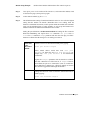
PortServer Default Settings
Serial Parameters:
(all ports) 9600 baud, No parity, 8 bits, 1 stop bit, VT100
terminal emulation
Root Login:
root
Root Password:
dbps
Digi, Digi International, PortServer, RealPort, and the Digi logo are trademarks or registered trademarks of
Digi International Inc. All other brand and product names are the trademarks of their respective holders.
© Digi International 2000
All Rights Reserved
Copyright © 2000 Digi International Inc. All Rights Reserved. http://www.digi.com
Disclaimer
This manual may contain inaccurate or erroneous information. This manual is subject to change
at any time. This manual, including all information contained herein, is provided “as is” without
warranty of any kind, either express or implied, including, but not limited to, any implied
warrantees of merchantability or fitness for particular purpose. Digi International Inc. makes no
representations, warranties, or commitments with regard to any data or information contained in
this manual. If you rely on data or information contained in this manual, such reliance is at your
own risk.
RESTRICTED RIGHTS:
For non-U. S. Government use:
These programs are supplied under a license. They may be used, disclosed, and/or copied only as permitted
under such license agreement. Any copy must contain the above copyright notice and this restricted rights
notice. Use, copying, and/or disclosure of the programs is strictly prohibited unless otherwise provided in
the license agreement.
For U.S. Government use:
Use, duplication, or disclosure by the Government is subject to restrictions as set forth in sub-paragraph
(c)(1)(ii) of the Rights in Technical Data and Computer Software clause of DFARS 52.227-7013.
Page ii PortServer Terminal Server
Table of Contents
PREFACE................................................................................................................................VI
CONVENTIONS USED IN THIS MANUAL .......................................................................................... VI
Keyboard Entry ......................................................................................................................vi
Typefaces ...............................................................................................................................vi
ELECTRONIC EMISSION NOTICES ................................................................................................. VII
Federal Communications Commission (FCC) Statements ......................................................vii
Industry Canada Compliance Statements...............................................................................vii
INTRODUCTION .....................................................................................................................1
PORTSERVER QUICK START..............................................................................................3
Configuring the PortServer over the Ethernet ..........................................................................5
COMMAND REFERENCE.................................................................................................... 29
ABBREVIATIONS ......................................................................................................................... 29
PORTSERVER HELP SCREENS ...................................................................................................... 30
PORTSERVER EDITING KEYSTROKES ........................................................................................... 31
PORTSERVER COMMANDS........................................................................................................... 32
ADMIN ....................................................................................................................................... 32
BOOT ......................................................................................................................................... 32
CPCONF ...................................................................................................................................... 33
EXIT........................................................................................................................................... 34
INFO .......................................................................................................................................... 34
KILL........................................................................................................................................... 36
NEWPASS.................................................................................................................................... 37
PING .......................................................................................................................................... 37
QUIT .......................................................................................................................................... 38
SET ............................................................................................................................................ 39
Range.................................................................................................................................... 39
Saving to EEPROM............................................................................................................... 40
altip....................................................................................................................................... 41
arp......................................................................................................................................... 42
config.................................................................................................................................... 43
Booting the PortServer Software with Remote Boot ......................................................................... 44
flow....................................................................................................................................... 45
host ....................................................................................................................................... 47
keys....................................................................................................................................... 48
line........................................................................................................................................ 49
logins .................................................................................................................................... 50
Character Strings ............................................................................................................................. 50
ports...................................................................................................................................... 52
route...................................................................................................................................... 54
terms ..................................................................................................................................... 55
users...................................................................................................................................... 57
PortServer Terminal Server Page iii
SNMP ......................................................................................................................................... 59
WHO .......................................................................................................................................... 60
REMOTE ACCESS COMMANDS ..................................................................................................... 61
CLOSE ........................................................................................................................................ 61
MODE......................................................................................................................................... 61
RLOGIN ...................................................................................................................................... 62
SEND.......................................................................................................................................... 63
STATUS ...................................................................................................................................... 63
TELNET ...................................................................................................................................... 64
APPENDIX.............................................................................................................................. 65
REALPORT PROTOCOL ................................................................................................................ 67
MASTER TROUBLESHOOTING PROCESS ........................................................................................ 68
Introduction........................................................................................................................... 68
Master Troubleshooting Process ............................................................................................ 68
TROUBLESHOOTING PROCEDURES ............................................................................................... 71
Procedure 1: Troubleshooting TFTP ...................................................................................... 71
Procedure 2: Resetting the PortServer.................................................................................... 73
Procedure 3: Telnet - Receiving No Login Prompt ................................................................. 73
Procedure 4: Performing a telnet to a port.............................................................................. 74
Procedure 5: Checking the PortServer Port Settings............................................................... 75
Procedure 6: Testing Port Communication............................................................................. 76
Procedure 7: Disconnecting Telnet ........................................................................................ 76
Procedure 8: Checking LED Indicators: OFC On?................................................................. 77
SIMPLE NETWORK MANAGEMENT PROTOCOL (SNMP) ................................................................ 78
Configuring the SNMP Agent ............................................................................................... 78
SNMP Protocol...................................................................................................................... 79
PORTSERVER FRONT PANEL........................................................................................................ 81
SEND (Serial Activity).......................................................................................................... 81
ETHERNET (Ethernet Activity)............................................................................................ 82
PORTSERVER BIOS .................................................................................................................... 83
Power On Self Test (POST) Sequence ................................................................................... 83
USER DIAGNOSTICS .................................................................................................................... 85
Video Display Diagnostics..................................................................................................... 85
Front Panel Display Diagnostics............................................................................................ 86
Basic Test Descriptions ................................................................................................................... 86
PORTSERVER SECURITY.............................................................................................................. 89
RESETTING THE PORTSERVER TO FACTORY DEFAULTS................................................................. 92
DEVICES AND WIRING CONSIDERATIONS ..................................................................................... 93
Configuring PortServer Ports as Specific Devices .................................................................. 93
SERIAL DEVICE TYPE CHARACTERISTICS TABLE .......................................................................... 96
PRINTERS ................................................................................................................................... 97
Configuring a Printer ............................................................................................................ 97
Connecting a Printer ............................................................................................................. 97
Printing a File ....................................................................................................................... 97
Page iv PortServer Terminal Server
MODEMS.................................................................................................................................... 98
Notes on Configuring Modems .............................................................................................. 98
Configuring CU and UUCP to dial out without RealPort........................................................ 99
RTTY Program ................................................................................................................... 101
RJ CONNECTORS ...................................................................................................................... 103
10 Pin RJ 45 Plugs .............................................................................................................. 104
8 Pin RJ 45 Plugs ................................................................................................................ 105
6 Pin RJ 11 Plugs ................................................................................................................ 106
4 Pin RJ 11 Plugs ................................................................................................................ 107
Digi RJ-45 to DB-25 Cable Legs ......................................................................................... 108
Connecting Modems............................................................................................................ 109
Altpin.............................................................................................................................................109
MULTIPLE SESSIONS ................................................................................................................. 110
Switching to another session................................................................................................ 111
Closing a session ................................................................................................................. 111
How to use Multiscreen Multisession................................................................................... 111
Configuring Multiscreens .................................................................................................... 112
PORTSERVER PORT NUMBERS ................................................................................................... 113
SPECIFICATIONS ....................................................................................................................... 114
INDEX ................................................................................................................................... 115
PortServer Terminal Server Page v
Preface
Conventions Used in this Manual
Certain conventions are used in this manual with respect to keyboard entry and typefaces:
Keyboard Entry
•
Single keystrokes are enclosed in angle brackets (e.g. <Enter>, <Esc>, etc.)
•
Control keys (i.e. keys which are struck while holding down the <Ctrl> key) are shown as
single keystrokes. For example, “<Ctrl-A>” means hold down the <Ctrl> key while striking
the <A> key. Similarly, “<Alt-A>” means hold down the <Alt> key while striking the <A>
key.
•
“Arrow keys” refers to the up, down, right and left arrow keys (<↑>, <↓>, <→>, <←>).
•
When you are asked to enter a command, type the text shown, then press <Enter>.
Typefaces
•
Examples of output to your computer screen are shown in mono-spaced characters.
•
Commands and data that you are to enter via your keyboard are shown in mono-spaced
characters.
•
Variable information within a typed entry is shown in italics. For example, if you are asked
to enter cp file_name path, type “cp”, followed by a space, then the name of the file to be
copied, another space, and the directory path to which the file is to be copied.
Page vi PortServer Terminal Server
Electronic Emission Notices
Federal Communications Commission (FCC) Statements
This equipment has been tested and found to comply with the limits for Class A digital devices
pursuant to Part 15 of the FCC Rules. These limits are designed to provide reasonable protection
against harmful interference when the equipment is operated in a commercial environment. This
equipment generates, uses, and can radiate radio frequency energy, and if not installed and used
in accordance with the instruction manual, may cause harmful interference to radio
communications. Operation of this equipment in a residential area is likely to cause harmful
interference, in which case the user will be required to correct the interference at his own
expense.
Only devices certified to comply with the limits for a Class A computing device may be attached
to this equipment. Operation with noncertified device(s) is likely to result in interference with
radio and TV reception.
This equipment is intended for commercial use only and is not suited for operation in Class B
environments.
The use of shielded I/O cables is required when connecting this equipment to any and all optional
peripheral or host devices. Failure to do so may violate FCC rules.
Industry Canada Compliance Statements
This Class A digital apparatus meets the requirements of the Canadian Interference Causing
Equipment Regulations.
Cet appareil numérique de la classe A respecte toutes les exigences du Règlement sur le matériel
brouilleur du Canada.
PortServer Terminal Server Page vii
Notes:
Page viii PortServer Terminal Server
Introduction
The Digi PortServer intelligent terminal server gives you the ability to
connect up to 16 RS-232 asynchronous serial devices (such as terminals
and printers) to an Ethernet network. Both Twisted Pair (10BaseT) and
Thinnet (10base2) cabling standards are supported via the appropriate
connectors on the side of the PortServer box.
Description
The PortServer hardware features a 20 MHz 80186 microprocessor and
a 83902 16-bit network interface controller. Other features include one
megabyte of RAM, 256K of ROM, up to 8k x 8 of EEPROM, and
16c554 UARTs. Self-tests on power-up help ensure reliability. Frontpanel LEDs and controls can be used for diagnostic testing and performance checks, monitoring either RS-232 or Ethernet activity.
Operating software is in firmware, but can also be downloaded from a
connected server or workstation via TFTP (Trivial File Transfer Protocol), meaning that the PortServer operating system can always have the
most current software without changing the firmware.
After the power-up self-tests and loading of the operating software
(either from firmware or downloaded), the PortServer software sends
login messages to all connected terminals. (Ports set up as printers or
modems do not receive login messages; the factory default sets all ports
as terminals.)
Operation
Overview
When they get the login prompt, users can log in to the PortServer’s
on-board operating system. Depending upon their privilege level (as
defined by the system administrator), commands can now be issued to
the PortServer software to change parameters or connect to one of the
network systems. The PortServer software allows the system administrator to set up password-protected accounts with various privilege
levels to limit certain users or terminals to restricted access to systems
on the network.
PortServer Terminal Server Page 1
Besides terminals, PortServer serial ports can be configured as modem
ports (incoming, outgoing or bi-directional) or printer ports. These
options require knowledge of your host’s operating system to get it to
“see” the devices connected to the ports. For supported operating
systems, Digi’s RealPort port control protocol gives powerful control in
accessing the remote PortServer ports.
Help
The PortServer software features extensive help functions. From the
main command shell (entered after login), entering a question mark
(“?”) brings up a list of commands and descriptions. Entering a
command followed by “?” produces a list of subcommands and their
descriptions.
PortServer
Highlights
•
Sixteen high-speed asynchronous serial ports, each with full
modem control and hardware or software flow control.
•
Data rates of up to 57,600 bps.
•
Multiple PortServer boxes can be attached to the network, limited
only by the capacity of the network.
•
Full on-board system diagnostics display results on front panel LED
indicators, or on a connected terminal.
•
LED indicators display RS-232 signal conditions plus input and
output flow control status for any port, or Ethernet activity.
•
Optional remote booting via TFTP allows firmware upgrades
without hardware changes.
•
Also:
Page 2 Introduction
Printer support.
Password access security.
Extensive help functions.
Statistics reporting.
Industry standard twisted-pair and thin-net connectors.
PortServer Quick Start
This “Quick Start” Getting Started section will help you quickly get your PortServer terminal
server up and running. Wherever possible, the factory default settings are used. Later, once you
have verified that the PortServer can communicate with your network, you can fine-tune the network and terminal parameters for optimum performance.
Plug in the PortServer power supply, and connect the PortServer to the Ethernet
Step 1.
Turn off the power switch on the PortServer unit.
Before connecting the PortServer box to the Ethernet network, be
sure to turn the power switch on the PortServer off. Also, when connecting peripheral devices to the PortServer connectors, both the
peripheral and the PortServer's power switches must be turned off.
Plugging any electronic device into another device under power can
cause damage to one or both of the devices.
Step 2.
Connect your network cable to the appropriate connector on the left side of the PortServer. Be sure to follow your network system's instructions and precautions on
connecting devices to the network.
If you are using a Thinnet (10Base2) cable, plug the cable into the BNC coaxial
connector. Make sure the selector switch is in the left-hand position.
If you are using a Twisted Pair (10BaseT) cable, plug the cable into the 10BaseT
connector. Make sure the selector switch is in the right-hand position.
Step 3.
Make sure the PortServer’s power switch is turned off, then plug the transformer’s
power connector into the DIN connector on the left side of the PortServer’s case.
Now plug the PortServer’s power adapter into a standard AC outlet.
PortServer Terminal Server Page 3
Connect a control terminal to the PortServer
The PortServer is controlled from a terminal (or PC with terminal emulation software) connected
to Port 1 on the PortServer’s back panel. (Any port can be used, but we will use the convention of
Port 1 here.) In some installations, the PortServer can be controlled directly over the Ethernet;
see Configuring the PortServer over the Ethernet on page 5.
Step 1.
Turn the PortServer’s power switch OFF.
Plugging any electronic device into another device under power can
cause damage to one or both of the devices.
Step 2.
Plug your serial terminal into Port 1 on the back of the PortServer box. A 10-pin RJ45-to-DB-25 cable is included with your PortServer for this purpose.
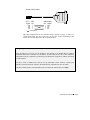
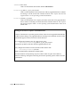
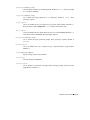
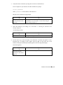
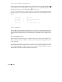
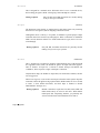
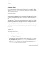
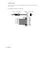
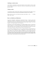
The following diagram shows a simple three-wire cable for connecting a terminal to
the PortServer. Usually, serial terminals and printers need only a three-wire
connection. The PortServer supports XON/XOFF (software) handshaking, so the
only signal lines necessary are Transmitted Data (TxD), Received Data (RxD) and
Signal Ground (SG). Cables must be shielded to remain in compliance with FCC
certification requirements, and the shield should be connected to Chassis Ground
(GND) at one end of the cable run.
Page 4 Quick Start
Simple 3-Wire Cable
RJ-11 - 4 Pin
Signal Pin
GND
TxD
RxD
SG
(
DB-25 Male
Pin Signal
1
2
3
4
1
2
3
7
GND
TxD
RxD
SG
= Cable Shield)
This same configuration can be constructed using 6 pin RJ-11 plugs, or either 8 or
10 pin RJ-45 plugs. See “RJ Connectors” on page 103 for the relationship of the
various sizes of RJ connectors to the 10 pin RJ-45 jack.
Configuring the PortServer over the Ethernet
If the IP address has not been set, the PortServer will attempt to use RARP (Reverse Address
Resolution Protocol) to determine its IP address. If this succeeds, the rest of the PortServer
configuration may be completed by connecting to the PortServer using telnet, without connecting
a serial terminal.
For this to work, a RARP server must be set up somewhere on the network. Consult your
operating system and network software documentation for information on how to do this.
(On many UNIX systems, such information can be found in the manual entry for rarpd).
PortServer Terminal Server Page 5
Connect other terminals and peripherals to the PortServer
At this point you may wish to connect other devices (terminals, modems or printers) to the
PortServer. If you’d prefer to “play with it” a bit and add other peripherals later, skip this part
and go to the next section, Log in and Configure the PortServer on page 9.
Terminals
Attach terminals to the other ports as previously described, plugging the RJ-45 or RJ-11
connectors (from the terminals) into the appropriate sockets in the back of the PortServer. All of
the ports are equal, and you can configure any port for any device. Make sure the power is off on
the PortServer and the terminals!
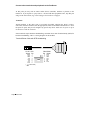
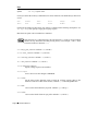
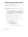
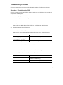
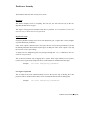
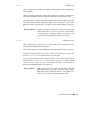
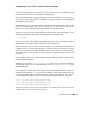
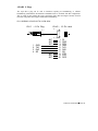
Some terminals require hardware handshaking; most that do use Data Terminal Ready (DTR) for
hardware handshaking. Here is a wiring diagram for this method:
Terminal/Printer Cable with DTR Handshaking
RJ-45 - 8 Pin
Signal Pin
DSR
RTS
GND
TxD
RxD
SG
CTS
DTR
(
Page 6 Quick Start
1
2
3
4
5
6
7
8
= Cable Shield)
DB-25 Male
Pin Signal
4
5
1
2
3
7
20
RTS
CTS
GND
TxD
RxD
SG
DTR
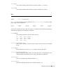
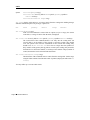
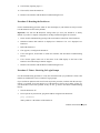
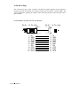
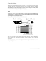
A more inclusive cable (necessary if you are going to set your port device as a host) is a full 10wire null-modem cable:
Full 10-Wire Null Modem Cable
Pin 10
Pin 1
RJ-45 - 10 Pin
Signal Pin
TxD
RxD
RTS
CTS
DSR
SG
DCD
DTR
RI
GND
(
5
6
3
8
2
7
10
9
1
4
DB-25 Male
Pin
Signal
2
3
4
5
6
7
8
20
1
22
TxD
RxD
RTS
CTS
DSR
SG
DCD
DTR
RI
GND
= Cable Shield)
PortServer Terminal Server Page 7
Modems
The easiest way to connect modems is to use Digi’s RJ-45 to DB-25 straight-through cables,
which offer full 10-pin connections for full modem control. (You may find ten-pin RJ-45
connectors difficult to find in the retail market). Here are the choices and part numbers:
DB-25 Male
DB-25
Female
DB-9 Male
24 Inch Cables
61020024
61030024
61070024
48 Inch Cables
61020048
61030048
N/A
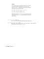
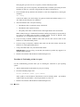
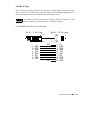
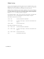
If you wish to build your own modem cables, follow the diagram below. Cables must be shielded
to remain in compliance with FCC certification requirements, and the shield should be connected to Chassis Ground (GND) at one end of the cable run.
Full 10-Wire Modem Cable
Pin 10
Pin 1
RJ-45 - 10 Pin
Signal Pin
RI
DSR
RTS
GND
TxD
RxD
SG
CTS
DTR
DCD
(
1
2
3
4
5
6
7
8
9
10
DB-25 Male
Pin
22
6
4
1
2
3
7
5
20
8
Signal
RI
DSR
RTS
GND
TxD
RxD
SG
CTS
DTR
DCD
= Cable Shield)
Now connect the modem(s) to the other ports as previously described, plugging the RJ-45 or RJ11 connectors from the modems into the appropriate sockets in the back of the PortServer. Again,
make sure the power is off on the PortServer and the modems!
If you want to use 8-pin RJ-45 to DB-25 adapters, a software feature called ALTPIN has been
incorporated into the PortServer software to swap the DCD and DSR signals. This makes DCD
available on pin 1 of an 8-pin RJ-45 connector. See Altpin on page 109.
Page 8 Quick Start
Printers
Serial printers can have different wiring requirements because of their manufacturer’s interpretations of the RS-232 “standard.” For those printers that can work with software handshaking
(also called “XON/XOFF”), the three-wire hookup for terminals shown on page 5 will work well.
Printers that require hardware handshaking (sometimes referred to as “DTR/DSR”) should work
with the terminal hardware handshaking wiring scheme shown on page 6. (Some Okidata
printers use a control signal on pin 11, called Supervisory Send Data (SSD) instead of DTR. In
this case, simply connect CTS on the RJ-45 side to pin 11 of the DB-25, instead of pin 20.)
If your printer manufacturer suggests a different wiring scheme, use it. Cables must be shielded
to remain in compliance with FCC certification requirements, and the shield should be connected to Chassis Ground (GND) at one end of the cable run.
This same configuration can be constructed using 6 pin RJ-11 plugs, or either
8 or 10 pin RJ-45 plugs. See “RJ Connectors” on page 103 for the relationship
of the various sizes of RJ connectors to the 10 pin RJ-45 jack.
Make sure the power is turned off on both the PortServer and the printers, and connect the
printers to the other ports as previously described.
Log in and Configure the PortServer
Step 1.
Turn on the terminal (or PC running terminal emulation software). Set the terminal
parameters to VT-100 emulation, 9600 baud, 8 data, 1 stop, and no parity.
(These are the factory default PortServer settings. While the PortServer can be
instructed to change these parameters, the terminal must be set to these default
values at first, in order to communicate with the PortServer software to change the
parameters!)
Step 2.
Turn the PortServer’s power switch on.
Step 3.
The PortServer firmware’s Power On Self Test (POST) sequence will now run automatically, displaying different messages in the 7 segment LED display as it performs
different tests. If no errors are detected, the 7 display should end up displaying AC,
and the ten LEDs will each go on in sequence.
PortServer Terminal Server Page 9
Step 4.
When AC is showing on the PortServer display, press the Return or Enter key on
your keyboard; you should get the login: prompt. Enter root. When asked for
the root password, enter dbps:
login: root
passwd:
#>
(Note in this screen dump that the password is not echoed to the screen.) When you
see the #> prompt, you are logged in.
Step 5.
Now you need to enter some network configuration information for the PortServer’s
network parameters configuration table, using information available from your
network administrator (or network documentation). Examples here will have
“phony” numbers that you will have to replace with your own information.
IP Address
First, you need to set an IP address for the PortServer unit.
Your network administrator can give you an appropriate
address to use. Assuming an IP address of 192.83.159.1 (for the
sake of this example), enter the following command:
#>set config ip=192.83.159.1
#>
(Again, enter the IP Address as assigned by your network administrator, not the example address shown above!)
Node Name
Enter the node name you have assigned for the PortServer. This
example uses “termserver”:
#>set config myname=termserver
#>
Domain Name
If applicable, enter the name of the domain that the PortServer
is part of. The default name is “DOMAIN”; this example uses
“arnold.org”:
#>set config domain=arnold.org
#>
Page 10 Quick Start
Domain
Server’s
Name
If you have one, enter the IP address of the IP Name Service
machine that will translate names to addresses. This example
uses “192.83.159.2”:
#>set config nameserv=192.83.159.2
#>
Note that if you do not have an IP Name Service machine, you
can use the PortServer’s Set Host commands to build a table
of names and their IP addresses. (See page 47.)
Network
Subnet
Mask
Set your network subnet mask. (The PortServer’s default
setting is 255.255.255.0); that’s also the mask used in this
example:
#>set config submask=255.255.255.0
#>
Gateway
Address
If you have a gateway, set its IP address. (The default setting of
255.255.255.255 is used in this example):
#>set config gateway=255.255.255.255
#>
There are other PortServer parameters that can be configured. These are covered
individually in the Command Reference chapter.
PortServer Terminal Server Page 11
Testing the network connection
You should now be able to establish communications with another network machine. (You will
need to know the IP Address of the other machine.) Enter the following ping command to test
the connection:
#>ping 192.83.159.227
#>
(Again, the IP address “192.83.159.227" shown above is for example only. Use an IP address that
is valid for your network.)
The PortServer software should respond:
192.83.159.227 is alive
#>
If you do not see the “It is Alive!” message, check the IP address set for the PortServer, as well as
that of the target machine. Check your physical network cable connection. You can also use the
PortServer’s front panel to check Ethernet activity—see PortServer Front Panel on page 81.
Page 12 Quick Start
Set up ports for your uses
Your next step would be to configure individual PortServer ports for your own specific uses. This
section sets up these example ports:
•
A wyse60 terminal on port 2, running at 38400 baud with software flow control
•
A printer with hardware flow control on port 3
•
A bi-directional modem with hardware flow control on port 4
Security Levels
Root Login is required for setting up ports, as it allows complete access to all PortServer options. The root user can write
and save the configurable parameters for any port, and the
root user sets up the “regular” logins for other users.
Except for parameter changes to his or her own PortServer
port, a “regular” user cannot configure any of the PortServer
parameters.
The “root” login is always present, and must always have a
password. It is not possible to remove the root user entry, or
delete the root password. It is possible to change the root
password with “newpass” (see page 37), and it is also possible for you to forget the root password if you change it! (In
this unfortunate event, see Resetting the PortServer to
Factory Defaults on page 92). The factory default root password is dbps.
Root level access is required for setting the ports as shown in
these examples.
Also see PortServer Security on page 89
Note that all changes made here are by default saved to EEPROM memory. The root user can
choose not to permanently change settings (see Saving to EEPROM on page 40); as a security
measure, by default “regular” users cannot save parameters permanently.
PortServer Terminal Server Page 13
Terminal Setup Example
(Wyse60 terminal on port 2, running at 38400 bps with software
flow control)
Step 1.
Turn off the power to the terminal and the PortServer, and connect the Wyse
terminal to Port 2. Power up again.
Step 2.
At the Port 1 control terminal, log in as root.
We’re still using Port 1, but any terminal can be used to make PortServer
configuration changes, as long as the user logged in as root, or has gained root
privileges with the admin command (page 32)—which as you’d suspect also requires the root password.
Step 3.
Again, the default settings are VT-100 emulation, 9600 baud, 8 data, 1 stop, and no
parity. For this example, we will change the Port 2 terminal type to wyse60, the baud
rate to 38400, and select software flow control for both incoming and outgoing data.
Setting the terminal type and baud rate will require these Set commands: set
port, set flow and set line. The set command’s range parameter will also
come into play, to tell the PortServer software that the changes we are making are to
Port 2.
Terminal
Type
Set the terminal type for Port #2 by typing:
#>set port termtype=wy60 range=2
Note that the terminal type names depend upon the conventions
accepted by your network’s host operating system; wy60 in the
above example stands for a Wyse 60 terminal.
The range=2 parameter tells the PortServer software that this
command is to affect Port #2; if range=2 had not been added,
the port we’re connected to (Port #1) would have been changed
to Wyse 60.
Baud Rate
Change the baud rate of Port #2 from the default 9600 baud to
38400 by typing:
#>set line baud=38400 range=2
Page 14 Quick Start
Flow Control
While the default port flow control setting is for software flow
control, let’s set it again just to make sure, by typing:
#>set flow ixon=on range=2
#>set flow ixoff=off range=2
(In the above, set flow ixon=on sets port #2 to use
software flow control (typically XON/XOFF) for output data.
set flow ixoff=off sets port #2 to turn off software flow
control for input data (keyboards shouldn’t need flow control).
Shorthand: The above two set flow commands could have
been set with one line:
#> set flow ixon=on ixoff=off range=2
Almost all commands can also be abbreviated; see
Abbreviations on page 29. For clarity, abbreviations will not be
used in these examples, and each command will have its own
line.
set commands are discussed in detail on page 39.
Printer Setup Example
(Printer with hardware flow control on port 3)
Step 1.
Turn off the power to the printer and the PortServer, and connect the printer, wired
as discussed on page 9, then power up again.
Step 2.
At the control terminal, log in as root.
Step 3.
The default settings when defining a port for printing are 9600 baud, 8 data, 1 stop,
and no parity. For this example, those will be fine, but we will need to set the flow
control.
Setting the port definition to printer and setting the flow control to DTR/CTS
(“hardware”) will require these Set commands: set port and set flow. The
set command’s range parameter will also come into play, to tell the PortServer
software that the changes we are making are to Port 3.
PortServer Terminal Server Page 15
Define Port
as Printer
Set Port #3 to be a Printer port by typing:
#>set port dev=prn range=3
Note that you did not have to set the port to be a terminal in the
previous example, because they all default to terminal as
shipped. To change Port #3 back to a terminal someday, you
would type “set port dev=term range=3.”
Again, the range=3 parameter tells the PortServer software
that this command is to affect Port #3; if range=3 had not
been added, the port we are connected to (Port #1) would have
been changed to a printer type—effectively ending our session
here until we logged in on another terminal to change it back!
Flow Control
Change the flow control for Port #3 to DTR (“hardware”) by
typing:
#>set flow cts=on range=3
set flow cts=on sets port #3 to use hardware flow control
for output data. (Note how CTS is connected to DTR in the
DTR wiring diagram on page 8.) Also note that the printer’s
flow control must match the hardware flow control we are
setting here.
You must also ensure that software flow control is off:
#>set flow ixon=off range=3
#>set flow ixoff=off range=3
set commands are discussed in detail on page 39.
Please note that using printers through the PortServer terminal server is very operating-system
specific and beyond the scope of this Quick Start discussion. See Printers on page 97 for more
information and application notes.
Page 16 Quick Start
Modem Setup Example
(Bi-directional modem with hardware flow control on port 4)
Step 1.
Turn off the power to the modem and the PortServer, and connect the modem, wired
as discussed on page 8, then power up again.
Step 2.
At the control terminal, log in as root.
Step 3.
The default baud rate setting of 9600 baud should be raised or lowered to the highest
setting that the modem can handle. (Remember that we’re talking about the
PortServer-to-Modem connection, not the speed at which the modem itself communicates over the telephone lines.) For this example, we will set up the PortServer-toModem connection at 2400 baud with hardware flow control.
Setting the port definition to bi-directional modem and setting the flow control to
RTS/CTS handshaking will require these Set commands: set port and set
flow. The set command’s range parameter will also come into play, to tell the PortServer software that the changes we are making are to Port 4.
Define Port
as Bidirectional
Modem
Set Port #4 to be a bi-directional modem port by typing:
#>set port dev=mio range=4
Other related choices would have been “set port
dev=min” for input-only, and “set port dev=mout” for
output only. “set port dev=mio” is for bidirectional
connections.
Again, the range=4 parameter tells the PortServer software
that this command is to affect Port #4; if range=4 had not
been added, the port we’re connected to (Port #1) would have
been changed to a modem type—effectively ending our session
here until we logged back in through the modem!
Baud Rate
Change the baud rate of Port #4 from the default 9600 baud to
2400 by typing:
#>set line baud=2400 range=4
PortServer Terminal Server Page 17
Flow Control
Change the flow control for Port #4 to RTS/CTS (“hardware”)
by typing:
#>set flow rts=on range=4
#>set flow cts=on range=4
(In the above, set flow rts=on sets port #4 to use hardware
flow control for input data. set flow cts=on sets port #4 to
use hardware flow control for output data.) Also note that the
modem must be set (through AT commands or DIP switches)
for hardware flow control.
You must also ensure that software flow control is off:
#>set flow ixon=off range=4
#>set flow ixoff=off range=4
set commands are discussed in detail on page 39.
Please note that setting up and using modems through the PortServer terminal server (or any
system, for that matter!) can get complicated quickly. See Modems on page 98 for more information and application notes.
Page 18 Quick Start
Set up a new user
A typical next step would be to set up a new user and password. For this example, we will:
•
Set up a new user for that Wyse 60 terminal on Port #2; the user’s login will be betty.
•
Give Betty the password MeBoss, and require that she give it whenever she logs in. (That is
the default, but we will make sure it is in place.) Passwords are case-sensitive, and limited to
eight characters in length.
•
Change the login prompt from the default login> to MegaCorp>.
•
Set up Betty’s secretary Rex as a user sharing Betty’s same terminal connected to Port 2,
with the user name rex and the password wannaB.
•
Set it up so that whenever Rex logs in he is connected directly to the host Corporate, without
the opportunity to manipulate the PortServer’s command shell.
The PortServer software offers many automatic login and automatic connection options. The
one mentioned above is tied to a specific user (rex); we could also have tied it to a particular
port, but since Betty and Rex share the same terminal, that would have left Betty without
access to the PortServer command line. You will want to carefully read (in the Command
Reference chapter) the entire section on the suite of set commands (page 39) to get an idea
of all of the PortServer options.
Making the above additions/changes to the PortServer will require the newpass command,
and these set commands: set host, set logins and set users. The set
command’s range parameter will also come into play on some commands, to tell the PortServer software that the changes we are making are to ports 1-16. (An eight-port
PortServer would use a range parameter of 1-8.)
PortServer Terminal Server Page 19
Create New
User “Betty”
Create “regular” (as opposed to root) user “Betty” by typing:
#>set users name=betty
The user names are stored in a table of users, viewable by
typing “set users” without any other parameters. As you
will later find, this way of getting the current PortServer setup
information works for all commands. And an easy way of
getting help on commands from the PortServer software is to
type the command sequence followed by a space and a question
mark, like “set users ?” to get a list of the set users options.
User names are case sensitive; “Betty” does not mean the
same as “betty” or “bEtTy” to the PortServer software.
IMPORTANT! Note that for new users, the user password is
the same as the username, with the same capitalization. Betty’s
password (until she changes it) is the same as her username
betty.
Require
Password
The user password is required by default (set to passwd=on),
but we will set it to ON just to make sure. Type:
#>set users name=betty passwd=on
(Yes, we could have done this at the same time as the first step.
We had to type in “user name=betty” here so that the PortServer software knew which user we were talking about.)
Page 20 Quick Start
Change
Betty’s
Password to
“MeBoss”
Passwords are case-sensitive, and limited to eight characters or
less. Changing the password can be done either by Betty
herself, or by the root user.
As root, set the password itself to “MeBoss.” Type:
newpass name=betty
The PortServer responds with
current passwd:
Type in “MeBoss”—note that it will not be echoed on the
screen. (You will be asked again for the new password, to make
sure it was typed correctly.)
Betty herself could have logged in (under her old, original
password of “betty,” and changed the password herself with the
newpass command. In that case, she would not have to add
“name=betty”.
Change
Login Prompt
to
MegaCorp>
Change the login prompt for port #2 from the default login> to
MegaCorp> by typing:
#>set logins logprompt="MegaCorp>" range=1-16
Note that if you wanted to change login prompt just for port #2,
you could have typed range=2; the above range command
changed the login prompt for all attached ports.
The login prompt length is 11 characters.
Also note the quotation marks around “MegaCorp>”; these
weren’t necessary in this example, but if a space had been
included (“Mega Corp>”) the quotation marks would have
been necessary to let the PortServer software know unambiguously what the new prompt string was.
Create New
User “Rex”
with
Password
“wannaB”
This is done in the same way as in the preceding example with
Betty. Type:
#>set users name=Rex passwd=on
Change the password (it is now “Rex”) as described for Betty.
PortServer Terminal Server Page 21
Have User
“Rex” bypass
PortServer
Command
Shell, connect
directly to
Host
“Corporate”
First, we create table entries for the host named “Corporate,”
including its IP address (152.83.151.1 is a “phony” name used
here for an example). Note that the “ip=” part is not necessary
if you have IP name service.
#>set host name=corporate ip=152.83.151.1
(You can inspect the Host table at any time by typing set
host with no other parameters.)
Next, we configure the PortServer software so that user “Rex”
is an auto user, automatically connected to a destination host
dest:
#>set users name=rex auto=on
#>set users name=rex dest=152.83.151.1
#>set users name=rex dport=23
(Again, 152.83.151.1 is a “phony” IP address; you would use
the real IP address for the host named “Corporate.”)
Setting dport is necessary to establish a terminal session with
the other host. The value 23 means a telnet-type terminal,
which will ask Rex to log in again at Corporate. An entry of
513 would specify Rlogin services, and Rex would automatically be logged in as long as his login on “Corporate” is
the same user name. Check your operating system documentation for service numbers.
set commands are discussed in detail on page 39.
Page 22 Quick Start
Telnet and Multisession
Here is an example of Betty logging in on her newly-configured terminal, logging into her company’s Corporate and Engineering hosts via telnet, switching between the two sessions, then
logging out.
The PortServer supports up to nine separate login sessions per port. For example, if your
company has host computers named Sales, Tech and Production, you can log into all three, and
switch among the different sessions and the PortServer command shell by using the telnet escape
key followed by a number or carriage return.
The default telnet escape key is <Ctrl-]> (Control/Right Square Bracket) and
can be changed—see set keys tesc=value on page 48.
To temporarily escape from a session to the PortServer command shell (perhaps to start another
session), type the telnet escape character followed by a carriage return. You may now start a
second session.
To go directly to the first session (bypassing the PortServer shell), type the telnet escape character
followed by a 1.
•
Type the telnet escape character followed by a 2 to go directly to the second session.
•
Type the telnet escape character followed by a carriage return to go to the PortServer
command shell.
•
From the PortServer command shell, type 1 or 2 as the first character on a line to go to the
session of that number.
•
As a shortcut, you can also toggle between your last two telnet sessions by pressing the telnet
escape character followed by “]” (<Ctrl-]> ]).
When you switch between sessions, the current session will continue on the next line of your
screen unless your terminal is capable of multi-screen operation (as entered in set ports
parameter—see page 52). You may need to hit the Enter key between sessions to see your
prompt.
Important!
AUTO users (like Rex in the previous example) cannot take advantage of
multisessions. (The purpose of the Auto option, after all, is to restrict a user or
port to a certain host).
PortServer Terminal Server Page 23
Log in as
“Betty”
The PortServer is already up and running. Betty turns on her
terminal, presses <enter> (if the login prompt is not already
showing) and sees:
MegaCorp>
She types in Betty and presses ENTER. Next she sees:
passwd:
Betty enters “MEBoss”. The PortServer responds “login
invalid...” because Betty got the case wrong. She logins in
again, and properly enters her new password “MeBoss”.
Start session
with
Corporate
At the PortServer’s “#>” prompt, Betty starts a session with her
company’s host computer called “Corporate” by typing:
#>telnet corporate
Note that she doesn’t have to give an IP address for
“Corporate” because her network has IP naming service. If it
did not, she could still have entered “telnet corporate”
as long as “corporate” and its IP address had been entered in
the PortServer’s host table, as described in “Set Host” on page
47. (The syntax for the telnet command is telnet
hostname|hostip [tcp port#]; that extra port # parameter is not
applicable here, but will be used in the next example.)
Betty logs in to Corporate using her login and password as set
up on that host.
Start new
session with
Engineering
Betty is now logged into Corporate through the PortServer. She
exits the Corporate login and goes back to the PortServer’s
command shell by typing the Telnet Escape sequence, which by
default is <Ctrl ]> (press the Control key and the right square
bracket keys at the same time) then pressing Return.
Back at the PortServer’s “#>” prompt, Betty starts a session
with her company’s host computer called “Engineering” by
typing:
#>telnet engineering
Again, she logs into the Engineering host using her login and
password as set up on that host.
Page 24 Quick Start
Switch
between
sessions
Betty’s session with Corporate is session #1, and her session
with Engineering is session #2. From her Engineering session,
she can switch to Corporate by typing <Ctrl-]> 1 (the telnet
escape character <Ctrl-]> followed by the number 1).
From her session on Corporate, she can switch to the
Engineering session by typing <Ctrl-]> 2, or switch back and
forth between the two sessions by pressing <Ctrl-]> ].
From either session, Betty can go back to the PortServer’s
command shell by typing the Telnet Escape sequence <Ctrl ]>
and then pressing Return. Once in the PortServer’s command
shell, Betty can start other sessions (up to nine), or perform
other operations. From the command shell, she can go to either
session #1 (Corporate) or session #2 (Engineering) by typing
the numbers 1 or 2 respectively as the first character on a line.
Log out of
Corporate
Betty now switches back to her Corporate session (using one of
the methods just described), and logs out of that session in the
way required by the host.
She then closes the telnet session and returns to the PortServer
command shell with the command:
close
Log out of
Engineering
In the same manner. Betty switches to the Engineering session,
(which is now session #1 by virtue of the original Corporate
session #1 being closed), logs out and closes the telnet session.
Log out of
PortServer
Back at the PortServer command shell, Betty exits her session
with:
exit
Note that the command quit works the same as exit. The
exit (or quit) command closes all active telnet or rlogin
sessions before exiting.
More information about multiple sessions and configuring
Multiscreens is in the appendix Multiple Sessions on page
110.
PortServer Terminal Server Page 25
Telnet and modems
In a previous part of this getting-started example, we installed a modem on Port #4, with DTR
(“hardware”) handshaking and configured for bi-directional (incoming and outgoing calls) use.
Here, Betty will telnet to that modem (from her Port #2 terminal to the modem on Port #4), use
“AT” type modem commands to set a fixed DTE interface and 2400 baud, then call an
information service.
The PortServer cannot switch the serial line baud rate depending on the kind of
connection made, so you should configure the modem to lock the serial line
speed at the highest baud rate the modem will go. (See your modem’s documentation.)
The telnet command is used to log into a remote system using the telnet protocol. (In this case,
calling from the PortServer Port #2 to Port #4, the PortServer itself is a “remote system!") Recall
that the telnet syntax is telnet hostname|hostip [tcp port#]. The hostname here is actually the
PortServer’s nodename that you configured when you first set up the PortServer—see page 10.
(In this example, the PortServer’s nodename was set to be termserver.) The tcp port# parameter
comes into play when telnetting to devices on the PortServer.
However, it is not possible to telnet to Port #4 by entering “telnet termserver 4”. By Digi
International convention, we add 2000 to the PortServer’s port number to create the tcp port
numbers. To reference the modem on port 4, use the value 2004.
See PortServer Port Numbers on page 113 for more detail.
Telnet to
Modem on
Port #4
Betty logs into her terminal on Port #2, then connects to the
modem installed on Port #4 with the telnet command:
telnet termserver 2004
Betty is now connected directly to the modem, and can directly
enter commands to the modem (like “AT” commands to Hayes
or Hayes-compatible modems). This example assumes Betty has
a 2400 baud Hayes-compatible modem attached to Port #4.
Page 26 Quick Start
Set Modem
for Hardware
Handshake
on Serial
Connection
In the modem setup example (page 17), the connection from
the PortServer to the modem was set to use RTS/CTS hardware
handshaking. Here, Betty tells the modem to use the same, by
typing:
AT&K3
(Betty is connected directly to the modem, so there are no command prompts.)
Set Modem
Baud Rate
In the modem setup example, the connection from the
PortServer to the modem was set at 2400 baud. Now Betty sets
the modem to 2400 baud.
(The exact command depends upon the brand and model of
modem; refer to your modem documentation when setting up
modem connections.)
Call Service
Betty now calls the online information service by telling her
modem to dial the telephone number (Hayes “AT” command
shown; your modems may be different):
ATDT 123-4567
(The example number “123-4567" above would be replaced by
the actual telephone number of the service you are calling.)
Log off
Betty exits the online service, then closes the connection to the
modem and logs off her terminal:
close
exit
Also see Modems on page 98 for information on configuring
modems, and using modems and the PortServer with UNIXbased operating systems.
PortServer Terminal Server Page 27
Page 28 Quick Start
Command Reference
This Command Reference is divided into these parts:
Abbreviations ...........................................................................................................(page 29)
PortServer Help Screens..........................................................................................(page 30)
PortServer Editing Keystrokes................................................................................(page 31)
PortServer Commands............................................................................................ (page 32)
telnet Commands..................................................................................................... (page 61)
rlogin ......................................................................................................................(page 62)
Abbreviations
All PortServer commands may be abbreviated to their shortest unique letters. Therefore the command:
set users name=jill
can be abbreviated to:
set u n=jill
You may type an asterisk (“*”) in place of “range=1-n” to reference all of the ports on the
PortServer.
PortServer Terminal Server Page 29
PortServer Help Screens
On-line help for the PortServer's command language is available to you through context-sensitive
help screens. Help is available by entering a “?” either by itself or after part of a command line.
The screen will tell you which parameters are available to complete the command line.
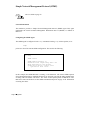
At the PortServer prompt, enter a “?” (question mark) with no other parameters to get the top
level help screen:
login: root
passwd:
#> ?
admin
exit
newpass
send
telnet
boot
info
ping
set
who
close
kill
quit
snmp
?
cpconf
mode
rlogin
status
#>
For help on a specific command, type the command name followed by a question mark. The
example below asks for help for the command info:
#> info ?
Displays or clears statistics tables.
syntax: info (table_name)|(table_cmd)
tables:
network
udp
ip
clear
icmp
tcp
#> info
After you enter a request for help, the PortServer software will print the text before
the “?” for you on the next command line, anticipating your next command. For
example, after the request for help with info ? above, notice how the next
command prompt includes the word info already typed.
Page 30 Command Reference
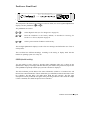
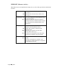
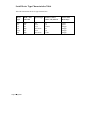
PortServer Editing Keystrokes
The following keystrokes can be used in editing commands sent to the PortServer from a terminal:
PortServer Terminal Server Page 31
PortServer Commands
These commands are specific to the PortServer.
admin
Syntax:
admin
The admin command allows you root privileges with the PortServer if you have previously
logged in as other than root. You will be asked for the root password.
boot
Syntax:
boot action=reset|eewrite
The boot command is used to reboot the PortServer, and requires root privileges.
If the command is entered as boot action=reset, the PortServer is reset using the current
parameters stored in memory (as when first powered on).
Use boot action=eewrite to reboot the PortServer using the factory default settings stored
in ROM. Note that in this event all user configuration will be lost!
See page 44 for Remote Booting via TFTP (Trivial File Transfer Protocol) of upgraded PortServer software.
Page 32 Command Reference
cpconf
Syntax:
cpconf tohost|fromhost hostname filename
cpconf term
The cpconf (copy configuration) command was added to allow saving and restoring the configuration of the PortServer to a disk file. The format of the save file is a list of the set
commands needed to set up the PortServer in the current configuration. These commands will be
read and acted on by the server (just as if the user had typed them on the command line) when
the configuration is restored.
Comment lines are allowed; the “#” character must be the first non-whitespace character on a
comment line. Such lines will be ignored by the PortServer command line interface.
There are two ways to store the data:
1.
Use a terminal emulator program that can capture text to a file and send the text file back to
the PortServer;
2.
Store and retrieve the configuration file from a host computer that serves TFTP file requests.
The TFTP server option is probably more convenient.
The command cpconf term will print the configuration directly to the terminal. To save the
configuration using a terminal emulation program, capture the output from the cpconf term
command into a file. To restore such a saved configuration, simply send the contents of the file to
the PortServer command line, which will run all the commands as if they were typed by the user
at the command line. If this method is used, it is very important that flow control works between
the PortServer and the terminal program.
To save the configuration to a TFTP server, use the command cpconf tohost hostname
filename. Either a true hostname or an ip address may be used for hostname. Filename is the
name of the file to be written; often this name must be a relative path name. (It depends upon the
particular TFTP server.) In many cases the TFTP server may require that the file already exist
and that it be world-writable before the TFTP transfer will be allowed.
An example of a way to create such a file on UNIX is:
touch /tftpboot/psconfig; chmod 666 /tftpboot/psconfig
To restore a configuration saved via TFTP, use the command cpconf fromhost hostname
filename.
Restoring the configuration takes quite a bit longer than saving it. This is because writing to the
EEPROM that stores the PortServer's configuration is a lot slower than reading.
PortServer Terminal Server Page 33
If an attempt is made to change the IP address when restoring over the network, the restoration
will fail because the PortServer will ignore any conversation on the old IP address. The save file
prints a “#” at the beginning of the set config ip=x.x.x.x command, commenting it out to
avoid the problem.
For security, it is probably wise to remove world write permissions on the save file once the
cpconf command has completed, to prevent unauthorized users from changing the file.
UNIX: Chmod 444 savefile
exit
Syntax:
exit
The exit command terminates the current PortServer login session. If you exit a session
without first closing it, PortServer will automatically do a close for you. (See the telnet
commands). Note that quit works the same as exit.
The command exit can also be used to give up root privileges temporarily acquired with the
admin command.
info
Syntax:
info table_name|table_command
The info command is used to either view PortServer network statistics tables or to clear their
contents. The information in the tables includes the statistics gathered since the tables were last
cleared with info clear.
The optional tables that can be viewed with info are:
network
ip
icmp
There is also a command to clear all of the info tables:
info clear
Root privileges are required for info clear.
Page 34 Command Reference
tcp
udp
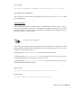
info tablename displays the following information (values shown are arbitrary examples).
These are actual screen dumps of a root-level session—note the root prompt (#>):
#> info network
Network statistics collected over last 129 minute(s).
UcastPktsRcvd
BcastPktsRcvd
bytes recvd
pkts recv err
receive intr
overflow intr
crc errors
buf alloc err
ip proto pkts
unknown type
:
:
:
:
:
:
:
:
:
:
480
5432
917683
0
5912
0
0
0
2289
1824
UcastPktsTxmt
BCastPktsTxmt
bytes txmtd
pkts txmt err
counter intr
pkts missed
frame errors
local pkts
arp proto pkts
broadcast pkts
:
:
:
:
:
:
:
:
:
:
741
4
48291
0
0
0
0
0
1792
5432
:
:
:
:
:
:
:
:
:
566
0
0
0
566
1300
0
743
0
:
:
:
:
:
:
:
:
:
:
:
:
0
0
0
0
0
0
0
0
0
0
0
0
#> info ip
Network statistics collected over last 129 minute(s).
ipInReceives
ipInNetBcast
ipInHdrErrors
ipInChkErrors
ipInLenErrors
ipInTypIcmp
ipInTypTcp
ipInDelivers
ipOut2Wait
ipForwDatagram
:
:
:
:
:
:
:
:
:
:
2294
1248
566
0
0
0
428
1728
4
0
ipInBcast
ipInSubBcast
ipInAddrErrors
ipInVerErrors
ipInClsErrors
ipInTypUdp
ipInTypUnknown
ipOutRequests
ipOutNoRoutes
#> info icmp
Network statistics collected over last 129 minute(s).
icmpInmsgs
icmpInEchos
icmpInAdrMskRp
icmpInRedirect
icmpInSrcQuenc
icmpInParmProb
icmpInTimestRp
icmpOutEchos
icmpOutAdrMskR
icmpOutRedirec
icmpOutSrcQuen
icmpOutParmPro
icmpOutTimestR
:
:
:
:
:
:
:
:
:
:
:
:
:
0
0
0
0
0
0
0
0
0
0
0
0
0
icmpInErrors
icmpInAdrMsk
icmpInEchoRprs
icmpInDstUnrec
icmpInTimeExcd
icmpInTimest
icmpOutMsgs
icmpOutAdrMsk
icmpOutEchoRp
icmpOutDstUnre
icmpOutTimeExc
icmpPutTImest
PortServer Terminal Server Page 35
#> info tcp
Network statistics collected over last 129 minute(s).
tcpInSegs
tcpInErrs
tcpInTcbErrs
tcpInDrpData
tcpInUrgBytes
tcpOutSegs
tcpOutRetxmts
tcpPassiveOpen
tcpEstabResets
tcpRtoAlgorith
tcpRtoMax
tcpTmrAllocErr
tcpBadReset
:
:
:
:
:
:
:
:
:
:
:
:
:
436
0
0
0
0
613
0
5
0
0
0
0
0
tcpInFast
tcpInCksErrs
tcpInNotOkErrs
tcpInDrpOwByte
tcpInNotInSeq
tcpOutResets
tcpActiveOpens
tcpAttemptFail
tcpCurrEstab
tcpRtoMin
tcpHolAllocErr
tcpBarSyn
:
:
:
:
:
:
:
:
:
:
:
:
365
0
2
0
0
0
0
0
3
0
0
0
:
:
:
:
0
4
0
1248
#> info udp
Network statistics collected over last 129 minute(s).
udaInDatagrams
udpInNameResp
udpInKme
udpOutDatagram
:
:
:
:
52
2
0
55
udpInErrors
udpInAddrResp
udpInUnknown
udpNoPorts
kill
Syntax:
kill tty=tty_number [action=eewrite]
The kill command is used to clear or reset the port named in the tty_number parameter. The
phrase action=eewrite is an optional parameter that should only be used as a last resort, as
it rewrites that port's configuration with the factory default settings. If you experience problems
with a connection, first try closing the session, shutting the terminal off, etc., before using the
kill tty=tty_number action=eewrite command.
The kill command requires root privileges.
Page 36 Command Reference
newpass
Syntax:
newpass [user=username]
Use the newpass command to create or change your current password. If you are at the root
level, be very careful not to forget your root password.
If you supply the optional name=username, another user’s password can be changed. Root-level
privileges are required to change another user’s password.
ping
Syntax:
ping hostipaddress|hostname [options . . . ]
The ping command is used to request ICMP echo responses from the specified host or network
gateway. If the host responds, ping will print (hostname) is alive; if no answer, it will print no
answer from (hostname). The options are:
fill=any_character
Fills the packet with the designated character.
npkts=num_packets
The number of packets to send. Allowable values are 1 to 30,000
(default=1). As a special case, enter -1; this will cause ping to send
one datagram per second and print one line of output for every
response received. In this case, ping will report round trip time and
packet loss statistics.
intv=interval
Specifies the time in milliseconds between ping requests. Default=1
second (1000 ms).
pksize=num_bytes
Used to specify the number of bytes in the packet; the allowable value
range is from 18 (the default value) to 1472.
PortServer Terminal Server Page 37
quit
Syntax:
quit
The quit command terminates your current login session. If you quit a session without first
closing it, PortServer will automatically do a close for you. (See the telnet commands). Note
that exit works the same as quit.
Quit can also be used to give up root privileges temporarily acquired with the admin
command.
Page 38 Command Reference
set
Syntax:
set tablename [options . . . ]
The set command is used to set or display various PortServer system and port parameters. The
different tables that can be substituted for tablename are:
altip
host
users
arp
route
config
terms
The variables in these tables are referenced by their table indexes.
flow
logins
keys
ports
line
The variables in these tables are referenced by port numbers.
Each of the tables will have their own options, as outlined in the following descriptions.
Range
As a part of any of the set commands, you have to specify which port or table entry the command is to affect. In the preceding list of tables, the names above the horizontal line are set
command variables referenced by their table index, while the items below the line may be
specified for modification by port number. If you do not specify a range, the set commands in this
section will affect only the port you are logged in from.
Specify the table entry, or a range of table entries, with the range option, in one of three formats:
set (command) range=singleport#
This tells the set command that the rest of the command affects the port number singleport#.
(Type in the rest of the command after the value for singleport#.)
set (command) range=startport#-endport#
This tells the set command that the rest of the command affects the port numbers startport#
through endport# . (Type in the rest of the command after the value for endport#.)
It is possible combine the preceding two methods, separated by commas:
set (command) range=port#,startport#-endport#,port#
PortServer Terminal Server Page 39
Multiple command options can be included in the same line with a single range option. For
example:
set line range=1-4 baud=2400 parity=E csize=7 stopb=1
will set the serial characteristics of ports 1 through 4 for 2400 baud, even parity, character size of
7 and 1 stop bit. This could also have been entered as:
set
set
set
set
line
line
line
line
range=1-4
range=1-4
range=1-4
range=1-4
baud=2400
parity=E
csize=7
stopb=1
Saving to EEPROM
Each set command also has an option to save to the PortServer's EEPROM. If you are logged in
as root, save is on by default. If you are not logged in as root, save is off by default. (Changes
made by a non-root user are valid only for the duration of the session.)
Non-root users can only set parameters for their individual ports. If non-root users wish to save
their parameters in EEPROM, they must use the command save=on as part of the port modification commands they use. The System Administrator must also have configured their port with
set logins write=on. (See logins write= on page 50.)
Since by default saves are automatic for root users, a root user making a temporary change to a
port should remember to add to the command the directive save=off.
Page 40 Command Reference
altip
Syntax:
set
set
set
set
altip [range=range]
altip ip=ipaddr group=port# | group#
altip rmip=ipaddress
altip rmrange range=range
The altip command allows you to telnet to a port or huntgroup using an IP address (or host
name). You must assign an additional IP address to the port or hunt group.
Options are:
group
ip
range
rmip
rmrange
save
set altip range=range
If the set altip command is entered with no options, or no options other than a
range, the current altip table entries for that range are displayed. (set altip with
no range prints the entire table.)
set altip ip=ipaddr group=port# | group#
This form of the command makes a new entry, or changes an existing entry. If the IP
address matches an existing entry, that entry will be modified. Otherwise a new table
entry will be created.
The IP address must be on the same network (or subnetwork) as the main IP address
of the PortServer. The group may be a port number or a group number. (See set ports
group=on page 53 for information on how groups of ports are assigned.)
set altip rmip=ipaddress
This form of the altip command remove entries from the table by ip address.
set altip rmrange range=range
This form of the altip command remove entries from the table by index numbers.
Up to 16 alternate IP address may be assigned.
Also see PortServer Port Numbers on page 113.
PortServer Terminal Server Page 41
arp
Syntax:
set arp [range=range]
set arp ip=ipaddr ether=etaddr [tim2liv=time]
set arp range=range rmarp=on
This sets or displays the arp (Address Resolution Protocol) table entries. The arp table maps IP
addresses to Ethernet addresses. In most cases, this is done automatically by the ARP protocol
and manual modification of this table will not be required. Making changes with ARP requires
root priveledges. The arp options are:
set arp range=range
If the set arp command is entered with no options other than a range, the current
ARP table entries for that range are displayed. (set arp with no range prints the
entire table.)
set arp ip=ipaddress ether=ethernetaddress [tim2liv=time]
The second form of the set arp command is used to add a new entry into the ARP
table. Set ipaddress to the ip address to be mapped (in the normal nnn.nnn.nnn.nnn
format) and set ethernetaddress to the six byte Ethernet address that this IP address
should be mapped to (such as 08:00:20:05:0b:da).
The optional parameter tim2liv can be set to the length of time, in seconds, to
keep an entry in the ARP table. If no value is specified, a default of 1200 seconds (20
minutes) is used.
set arp range=range rmarp=on
This is used to remove entries from the ARP table. Set range equal to the range of
table entries to be removed, using the numbers from the Index field when you view
the table using set arp.
You may define up to 16 arp table entries.
Page 42 Command Reference
config
Syntax:
set config option=value
This sets or displays the network parameters configuration table entries. Options are:
domain
netcx
gateway
submask
myname
ether
ip
boothost
nameserv
bootfile
More than one configuration option can be included in a command.
The set config command writes to EEPROM, and informs you of the number of
locations found bad and corrected in EEPROM memory. A non-zero number is
worrisome only when the number of errors begins to approach 64, the maximum
number of entries in the EEPROM patch table. Anyone with more than 40 corrected
errors should contact Digi Technical Support for assistance.
“EP” appears on the front panel display any time a write to EEPROM is in progress.
domain=domain_name
Specifies the domain name.
gateway=ipaddress
Sets the IP address of the gateway.
myname=PortServer's_name
Sets the node name of the PortServer box.
ip=ipaddress
Sets the PortServer's ip address.
nameserv=ipaddress
Specifies the name of the domain name server. If an address is not specified, the
host’s ip address must be entered using the set host covered on page 47.
realport=tcp_port_number
This is the RealPort TCP port number, which has a default value of 771 here and in
the RealPort drivers. If this number must be changed because of conflicts, remember
to change it both here and in the RealPort drivers.
PortServer Terminal Server Page 43
submask=subnet mask
Used to set the network subnet mask. Default=255.255.255.0
boothost=ip_address_of_host_with_bootfile
Used to set the IP address of the remote host with any upgraded PortServer software
for booting via TFTP (Trivial File Transfer Protocol). This requires that the host
supports TFTP— see the operating system documentation.
bootfile=filename_of_bootfile
Used to set the filename with complete path on the remote host of any upgraded PortServer software for booting via TFTP (Trivial File Transfer Protocol). This requires
that the host supports TFTP— see the operating system documentation. There is no
default name.
Booting the PortServer Software with Remote Boot
A feature of the PortServer operating system software is that it can be upgraded without ROM
or other hardware changes. Any upgraded software from Digi can be installed on a host on the
network that supports TFTP (Trivial File Transfer Protocol).
First, configure the PortServer box for remote boot by using
set config boothost=ip_address_of_host_with_bootfile
to specify the ip address of the host with the upgraded software on it.
Next, configure the PortServer for the filename of that software with
set config bootfile=filename
(Make sure that filename includes the complete path.)
Reset the PortServer unit by turning its power switch off, then on again. The PortServer
firmware will then go through its self-testing, then load its operating system software from the
specified host.
Page 44 Command Reference
TFTP Error Messages
The host with the bootfile may pass back a TFTP error message, which the PortServer will
display in the alphanumeric display. This message will be in the form En, where n can be one
of the following:
0
1
2
3
4
5
6
7
Error not defined, see error message (if any)
File not found
Access Violation
Disk Full or allocation exceeded
Illegal TFTP operation
Unknown transfer ID
File already exists
No such user
If the remote still will not work, push both arrow buttons ( 4 and 5 ) to boot from the
ROM, and check that the boothost ip address is correct, and that the bootfile path and name
are correct. Also ensure that your system supports TFTP.
To return to automatically booting from ROM, enter:
set config boothost=255.255.255.255
flow
Syntax:
set flow option=value
The set flow commands set or display the hardware and software flow control parameters for
RS-232 serial ports. set flow range is used to specify multiple ports, or one specific port.
Options are:
aixon
ixany
altpin
ixoff
cts
ixon
dcd
range
dsr
ri
dtr
rts
itoss
save
Each of the above will have their own options, as outlined in the following descriptions. (More
than one option can be included in a command.)
PortServer Terminal Server Page 45
aixon=on|off
Use auxiliary flow control characters (defined by set keys xona= and set keys
xofa=) for output flow control. Default=off
altpin=on|off
Setting Altpin ON switches the function of the DSR and the DCD inputs on the
interface connector, so that DCD is available when using an 8-pin RJ-45 connector
instead of a 10-pin RJ-45 connector. (See RJ Connectors on page 103.)
Default=off
cts=on|off
Use (or do not use) CTS (Clear To Send) for output flow control. Default=off
dcd=on|off
Use (or do not use) DCD (Data Carrier Detect) for output flow control. Default=off
dsr=on|off
Use (or do not use) DSR (Data Set Ready) for output flow control. Default=off
dtr=on|off
Use (or do not use) DTR (Data Terminal Ready) for input flow control. Default=off
ixoff=on|off
When ON, use software flow control (typically XON/XOFF) for input data.
Default=on
ixon=on|off
When ON, use software flow control (typically XON/XOFF) for output data.
Default=on
range=startport#-endport#
Specify a range of ports to be modified. If not specified, the command will act on the
current port. It is important to specify the port or port range when logged into the
PortServer remotely.
ri=on|off
When ON, use Ring Indicator (RI) for output flow control. Default=off
rts=on|off
When ON, use RTS (Request To Send) for input flow control. Default=off
save=on|off
Save or do not save the changes to EEPROM.
Page 46 Command Reference
host
Syntax:
set
set
set
set
host [range=range]
host name=hostname ip=ipaddress
host rmhost=hostname
host rmhost=on range=range
This sets or displays the host name table, which maps host names to IP addresses. If name service
is configured, this table is filled in automatically, and manual modification of this table will
probably not be required. Making changes with this command requires root privileges.
Options are:
ip name
range
rmhost
set host [range=range]
If the set host command is entered with no options (or just a range), it prints the
current host table (or a range of entries from the table).
set host name=hostname ip=ipaddress
This form of the set host command makes a new entry, or changes an existing
entry. Set hostname to the name of the host, and set ipaddress to the ip address of the
host. If the host name already existed in the table, the new ip address will replace the
old ip address; otherwise a new table entry will be created for this hostname and
address.
set host rmhost=hostname
This form of the set host command is used for removing entries from the host
table. set host rmhost=hostname removes the entry that refers to the hostname
set host rmhhost=on range=range
This form of the set host command is also used for removing entries from the
host table. set host rmhhost=on range=range is used to remove entries from
the host table by index number(s); these can be found in the table listing (by typing
set host with no options).
You may define up to 16 host table entries.
PortServer Terminal Server Page 47
keys
Syntax:
set keys option=value
Use keys to define the local key combinations for various functions. The different keys that can be
set are:
eof
tesc
erase
xon
intr
xoff
kill
xona
range
xoffa
save
Each of the preceding will have their own options, as outlined in the following descriptions. Use
set keys range= to specify a single port or group of ports.
More than one option can be included in a command.
If the character is a control character, the carat character (^) must be used to indicate
that the Ctrl key should be held while pressing the key. (For example, <Ctrl-C> must
be entered as the two characters ^C.)
eof=end_of_file_character. Default=^D (<Ctrl-D>)
erase=erase_character. Default=^H (<Ctrl-H>)
intr=interrupt_character. Default=^C (<Ctrl-C>)
kill=kill_character. Default=^U (<Ctrl-U>)
range=startport#-endport#
Specify a range of ports to be modified.
save=on|off
Save or do not save the changes to EEPROM.
tesc=value
Set the telnet escape character (used to break out of telnet sessions either to the
PortServer shell or to other telnet sessions). Default=^] (Control Right-Bracket)
xon=value
Use to set the XON Character you prefer. Default=^Q (<Ctrl-Q>)
xoff=value
Use to set the XOFF Character you prefer. Default=^S (<Ctrl-S>)
Page 48 Command Reference
xona=value
Use to set the auxiliary XON Character you prefer. Default=^Q (<Ctrl-Q>)
xoffa=value
Use to set the auxiliary XOFF Character you prefer. Default=^S (<Ctrl-S>)
line
Syntax:
set line option=value
Use line to view or modify serial line parameters. Use set line range= to specify a single
port or group of ports. Options are:
baud
onlcr
break
otab
csize
parity
error
range
inpck
save
istrip
stopb
Each of the preceding will have their own options, as outlined in the following descriptions.
(More than one option can be included in a command.)
baud=baudrate
Use to set the baud rate for the port. Legal values are:
50
110
150
300
600
1200
1800
2400
3600
4800
7200
9600
19200
38400
57600
break=ignore|send|escape
Used to ignore (default), or send an escape sequence when a telnet break command
is seen.
csize=5|6|7|8
Sets the Character size. Can be 5, 6, 7 or 8 bits per character. Default=8
error=ignore|null|parmk|dos
Tells the PortServer software what to do with parity errors. It can ignore the error
(default), change the error character to a null, or mark the error with an FF.
inpck=on|off
Turn on or off input parity checking. Default=off
istrip=on|off
When ON, strips the high order bit in each byte. Default= off
PortServer Terminal Server Page 49
onlcr=on|off
Use to map (ON) or not to map (OFF) NEWLINE characters to CR-NEWLINE on
output. Default=off
otab=on|off
Converts output tabs to eight spaces. Default= off
parity=O|E|N
Use to select Odd, Even or No parity. Default=N (no parity).
range=startport#-endport#
Specify a range of ports to be modified.
save=on|off
Save the changes to EEPROM.
stopb=1|2
Use to set the Stop Bits to 1 or 2. Default=1
logins
Syntax:
set logins option=value
Use this command to activate/deactivate login and password protection, define prompts and
startup messages. set logins range= is used to specify multiple ports, or one specific port.
Options are:
cmdprompt
passprompt
verbose
logprompt
passwd
login
range
write
save
Character Strings
Many of the values entered for logins are character strings. To include a space in a character
string, enclose the entire string in quotation marks. For example, to change the PortServer
login prompt to Enter login:, type:
set logins logprompt="Enter login:"
Each of the preceding will have their own options, as outlined in the following descriptions.
(More than one option can be included in a command.)
Page 50 Command Reference
cmdprompt=character_string
Use to define the PortServer command prompt. Default is digi>. (The root prompt
of ># cannot be changed.)
logprompt=character_string
Use to define the login prompt (up to 11 characters). Default is login:. Root
privileges required.
login=on|off
Use to set whether the user is required to log in before using terminal. Default=on.
Root privileges required. Important! login must be ON for Auto users.
write=on|off
Use to set whether the user (other than root) can save to the EEPROM. Default=off
(user cannot write to EEPROM). Root privileges required.
passprompt=character_string
Use to define the login password prompt. Root privileges required. Default is
passwd:
passwd=on|off
Use to set whether the user is required to give a password before using terminal.
Default=on
range=startport#-endport#
Specify a range of ports to be modified.
save=on|off
Save the changes to EEPROM.
verbose=on|off
Use to eliminate “connection” messages before the login prompt. (Useful to batch
programmers.) Default=on
PortServer Terminal Server Page 51
ports
Syntax:
set ports option=value
Use set ports to set or display device configuration parameters. set ports range is used
to specify multiple ports, or one specific port. Options are:
auto
group
bin
sess
dest
range
dev
save
dport
termtype
edelay
uid
Each of the preceding will have their own options, as outlined in the following descriptions.
(More than one option can be included in a command.)
auto=on|off
auto on is used in conjunction with uid, dest and dport, to set up a port so
that a user on that port will bypass the PortServer's command shell and automatically
connect to the defined destination. (Also see set users name=auto on page 57, which
is similar except that a specified User is always connected to the specified
destination, bypassing the PortServer's command shell, without regard to what port
that user is using.) Important! login must be set to on for Auto users—see set
logins login= on page 51.
bin=on|off
Used in conjunction with auto to specify a binary connection. Default=off
dest=IPaddress
Use to specify the destination for the auto port. (See set ports auto).
dev=value
Set the port to a device as indicated in value. Possible values are term, host, prn,
min, mout, mio:
term
host
prn
min
mout
mio
Set the port to be a terminal.
Set the port to mimic a modem for input only.
Set the port to be a printer.
Set the port to be a modem for input only.
Set the port to be a modem for output only.
Set the port to be a modem for input and output.
Also see Devices and Wiring Considerations on page 93.
Page 52 Command Reference
dport=remote_port#
Use to specify the port number an auto connect port should connect to. (See set ports
auto on page 52).
•
If set to 23, specifies telnet protocol services.
•
If set to 513, specifies Rlogin services.
•
If set to 0 (the default value), then checks the value of uid (below); if uid is
set to 0, then specifies telnet services. If uid has a valid user index #, then
specifies rlogin services.
Check your operating system documentation for service numbers.
edelay=value
Use to specify a delay time between packets transmitted under continuous data reception. Values from 1 to 100 are valid, where 1 stands for 10 milliseconds delay. (A
value of 2 would be 20 milliseconds, a value of 3 would be 30 milliseconds, a value
of 100 would be 1000 milliseconds or one second). Do not change unless you are
experienced with packet timing processes. Default=1 (10 ms)
group=group#
Assign a group number of like devices (output modems, for example) specified by
the range= value, so that a user can ask for by group number if he or she does not
care which particular port they get, but are satisfied with the first open one. Pick a
group number in the range 17-80 to avoid confusion or conflicts with the “regular”
port names. (See PortServer Port Numbers on page 113.)
sess=number_of_sessions
Use to set the maximum number of sessions any port can run; valid entries are from
1 to 9. Default=4. (There is a limit of 64 total sessions for all ports on the
PortServer.)
range=startport#-endport#
Specify a range of ports to be modified.
save=on|off
Save the changes to EEPROM.
termtype=terminaltype
Use to assign a terminal type to the port. The terminal type is used for the multiscreen/multisession feature (see page 110), and is reported to the remote host during
telnet negotiations.
uid=user_index#
Use to set the user index number (the number of the user as carried in the
PortServer's table). View the table by typing set users. (See set ports auto on
page 52.)
PortServer Terminal Server Page 53
route
Syntax:
set route [range=range]
set route net=network_address mask=ipmask gateway=ipaddress
metric=numhops
set route rmroute=on range=range
set route displays, adds entries to, or removes entries from the routing table. Making changes
with this command requires root privileges. Options are:
net
mask
gateway
metric
range
rmroute
set route [range=range]
If the set route command is entered with no options (or just a range), the current
route table (or a range of entries from the table) is displayed.
set route net=network_address mask=ipmask gateway=ipaddress metric=numhops
The second form of the command makes a new entry into the routing table. Set
network_address to the address of the network or host this routing entry should
cover. Set ipmask to the network / subnetmask for the network this routing entry
should cover, or 255.255.255.255 for a route to a single host. Set ipaddress to
the ip address of the gateway that ip packets covered by this routing entry should be
forwarded to. For the metric number, set numhops to the number of hops (number of
routers) between the local network and the destination.
set route rmroute=on range=range
The third form of the command removes entries from the routing table. Set the range
using the index numbers listed when the table is printed. (Display the table with set
route.)
You may define up to 16 route table entries.
Page 54 Command Reference
terms
Syntax:
set terms [range=range]
set terms termtype=terminal_type [npages=# of screens]
[clrseq=clear_escseq]
[swtseq=screen# pageswitch_escseq] ...
[save=on|off]
set terms rmterm terminal_type
set terms rmterm=on range=range
This command sets or displays the terminal types, and their associated escape sequences used
when switching between sessions. (See Multiple Sessions page 110, as well as your terminal's
manual.)
Making changes with this command requires root privileges.
More than one option can be included in a command. Options are:
clrseq
swtseq
npages
termtype
range
rmterm
save
set terms [range=range]
If set terms is entered with no options (or just a range), the current terminal table
is displayed.
set terms termtype=terminal_type [npages=# of screens] [clrseq=clear_escseq]
[swtseq=screen# pageswitch_escseq] ...
[save=on|off]
This form of the set terms command makes a new terminal table entry, or
changes an existing entry. Set terminal_type to the name of the terminal type; this
name should match the name used for the termtype in the set port command
(page 52), and must also match the name used by the hosts on your network for this
type of terminal. If termtype matches an existing entry, that entry will be modified by
this command; otherwise a new table entry will be created.
Use npages= to set # of screens to the number of pages of screen memory that the
terminal has. Use clrseq=clear_escseq to set the escape sequence that will clear
the terminal's current screen. swtseq is the escape sequence that will switch your
terminal to the different screen pages; you need to supply one swtseq=screen#
switch_escseq parameter for each terminal page. Set save=off if you do not want
to save the changes.
If the character is a control character, the carat character (^) must be used to
indicate that the Ctrl key should be held while pressing the key. (For example,
<Ctrl-C> must be entered as the two characters ^C.)
PortServer Terminal Server Page 55
Example:
This example sets up the user's default terminal (since no range is
specified) to a Wyse60, supporting three screens with a clear
sequence of <Ctrl-[> + (control-left bracket, plus key) and defines
keys to switch between the three screens.
set
set
set
set
terms
terms
terms
terms
term=wy60
term=wy60
term=wy60
term=wy60
npages=3 clrseq=^[+
swtseq=1^[w0
swtseq=2^[w1
swtseq=3^[w2
Note that the parameter term=wy60 must be repeated in each line
entered; otherwise the swtseq changes would not be made to the
wy60 termtype.
set terms rmterm terminal_type
This removes the terminal table entry that refers to the terminal_type.
set terms rmterm=on range=range
This removes entries from the table by the index numbers as shown when the
terminal table is listed by entering set terms.
Page 56 Command Reference
users
Syntax:
set users [range=range]
set users name=username [passwd=on|off] [auto=on|off]
[dest=IPaddress] [dport=tcp_port#]
set users rmuser=username
set users rmuser=on range=range
set users newname=newusername name=oldusername
This command sets or displays the user name table. Making changes with this command requires
root privileges. More than one option can be included in a command. Options are:
auto
range
dport
rmuser
dest
save
name
newname
passwd
set users [range=range]
If the set users command is entered with no options (or just a range), it displays
the current users table (or a range of entries from the table).
set users name=username [passwd=on|off] [auto=on|off]
[dest=IPaddress] [dport=tcp_port#]
This form of the set users command makes a new user entry, or changes an
existing user entry. Set username to the name of the user. If the name matches an
existing entry, that entry will be modified by this commandotherwise a new table
entry will be created. Setting passwd=on will require the user to enter a password
when logging in; setting passwd=off allows the user to log in without a password.
If a new user that requires a password is created, the initial password is the same as
the user name.
•
If auto is set to off, the user username is presented with the PortServer command line after logging in.
•
If auto is turned on, the user username will always be connected to the
destination specified by dest=IPaddress and dport=tcp_port#, completely
bypassing the PortServer command shell. (IPaddress is the IP address of the
host that this user should automatically be connected to, and tcp_port# is the
host TCP port that the connection should be made to: 23 means telnet, 513
means rlogin; the default 0 is mapped to rlogin. (Check your operating system
documentation for service numbers.)
PortServer Terminal Server Page 57
•
(Also see set port auto on page 52, which is similar except that a port is set up
so that any user on that port will bypass the PortServer's command shell and
automatically connect to the defined destination.)
•
Important! login must be set to on for Auto users—see set logins login= on
page 51.
set users newname=newusername name=oldusername
This is used to change the user name oldusername already in the table to the new
name newusername.
set users rmuser=username
This form of the command is used for removing entries from the users table, and
removes the entery that refers to username.
set users rmuser=on range=range
This form is used to remove entries from the table by index numbers, which can be
found in the table listing by typing set users with no other options.
You may define up to 16 user table entries.
Page 58 Command Reference
snmp
Syntax:
snmp [run=off | on] [auth_trap=off | on] [trap_dest=ipaddress]
[location=PortServer’s location]
The snmp command is used to configure and enable/disable snmp. The snmp community is
“public.” Snmp sets are not supported.
snmp run=on|off
This starts or stops the SNMP daemon. Default is Off.
snmp auth_trap=on|off
This configures SNMP to send or ignore authentication traps when an authentication
error occurs. Default is Off.
snmp trap_dest=IP address
This configures SNMP to send all traps to the IP address given.
snmp location="location of PortServer"
This gives SNMP the value of system.sysLocation, which is a text string that
describes the location of the box in a form meaningful to the user. This parameter is
optional. Note that the entry must be surrounded by quotation marks if there are
spaces used in the text.
snmp contact="Person to contact"
This gives SNMP the value of system.sysContact, which is the name of the person
responsible for managing the PortServer. This parameter is optional. Note that the
entry must be surrounded by quotation marks if there are spaces used in the text.
Entering snmp with no options prints out the current configuration.
Also see SNMP Protocol on page 79.
PortServer Terminal Server Page 59
who
Syntax:
who
The who command displays a list of the current users of the PortServer. Information includes
each user's name and tty, the number of sessions each user is using, and where each user is
connected from and connected to.
The output looks like:
#> who
tty username nsess
15 root
2
Page 60 Command Reference
connected_from
local_tty15
connected_to
local_shell
Remote Access Commands
The commands in this section are remote access related.
close
Syntax:
close
Closes the current tcp session (the session last escaped from) to reenter the PortServer operating
system’s command mode.
mode
Syntax:
mode [option=offlow]
The mode command is used to display telnet operating parameters.
#> mode
tty
15
15
bin
off
on
crmod
off
off
crlf
off
off
sess
1
2
hostname
poe
ctsi
bin
Enter mode bin=on or mode bin=off to turn bin (binary characters, both
directions) on or off. Default=off
crmod
Enter mode crmod=on or mode chmod=off to turn crmod on or off. This
adds line feed characters (010 dec) to and received carriage returns (013). This
does not affect any characters you type. (<CR> becomes <CR><LF>)
Default=off
crlf
Enter mode crlf=on or mode crlf=off to turn crlf on or off. This adds
line feed characters (010 dec) to and sent carriage returns (013). This does not
affect any characters you receive. (<CR> becomes <CR><LF>) Default= off
PortServer Terminal Server Page 61
rlogin
The rlogin command logs a user into a remote system.
syntax: rlogin hostipaddr|hostname [options]
options: [user=username]
[esc=escape_char]
To avoid entering your password when logging into a remote system, you may put the
PortServer's node name in the .rhosts file. You may also ask the remote system administrator
to make passwords globally unnecessary by entering the PortServer's node name in the remote
hosts /etc/hosts.equiv file.
Options:
user=username
You may specify another username for the remote login session; otherwise, the
remote username used is the same as your local username.
esc=escape_character
You may specify a different escape character for disconnecting from the remote host.
Normally you would close an rlogin session by typing “<CR> ~ .” (That is three
keystrokes: Carriage Return key / Tilde key / period key.) Use esc= to change the
tilde character (“~”) in this context.
If the character is a control character, the carat character (^) must be used to indicate
that the Ctrl key should be held while pressing the key. (For example, <Ctrl-C> must
be entered as the two characters ^C.)
Once you are connected via rlogin, you can escape back to PortServer command mode by
replacing the period in the rlogin escape sequence with your telnet escape character, followed
by a carriage return. You may also type your telnet escape character followed by a digit to switch
to an alternate telnet session.
Page 62 Command Reference
send
Syntax:
send telnet_special_character
This command transmits one of the following telnet special characters to the last active telnet
session:
abort output
are you there?
break
erase character
erase line
ao
ayt
brk
ec
el
escape
ga
ip
nop
synch
esc character
go ahead
interrupt process
no operation
synchronize process
For example, to send a break signal, type: send brk
status
Syntax:
status
The status command displays information on the current telnet session (if any), including the
peer you are connected to, and the current mode. Here's an actual example:
#> status
Connection 1: sunny
Escape character is ^].
PortServer Terminal Server Page 63
telnet
Syntax:
telnet hostname|hostip [port#]
The telnet command is used to log you into a remote system using telnet protocol. Once you are
connected via telnet, you can escape back to PortServer command mode by typing your telnet
escape character, followed by a carriage return. You may also type your telnet escape character
followed by a digit to switch to an alternate telnet session.
(Also see Multiple Sessions on page 110.)
Use the format telnet nodename port#+2000 to telnet to a device on a specific port of the
PortServer unit. Nodename is the PortServer's node name. By Digi International’s convention,
2000 is added to the port number; to reference a device on port 8, you would use the value 2008.
See PortServer Port Numbers on page 113 for a more detailed explanation.
Page 64 Command Reference
Appendix
Appendix Table of Contents
RealPort Protocol ...................................................................................................................... 67
Troubleshooting ........................................................................................................................ 69
Master Troubleshooting Process ......................................................................................... 69
Troubleshooting Procedures ............................................................................................... 72
Simple Network Management Protocol (SNMP)........................................................................ 78
PortServer Front Panel .............................................................................................................. 81
PortServer BIOS........................................................................................................................ 83
User Diagnostics ....................................................................................................................... 85
PortServer Security.................................................................................................................... 89
Resetting the PortServer to Factory Defaults.............................................................................. 92
Devices and Wiring Considerations........................................................................................... 93
Serial Device Type Characteristics Table................................................................................... 96
Printers ..................................................................................................................................... 97
Modems .................................................................................................................................... 98
RTTY Program ................................................................................................................ 101
RJ Connectors ......................................................................................................................... 103
Multiple Sessions .................................................................................................................... 110
Configuring Multi Screens ............................................................................................... 112
PortServer Port Numbers......................................................................................................... 113
Specifications.......................................................................................................................... 114
PortServer Terminal Server Page 65
Page 66 Appendix
RealPort Protocol
RealPort is a protocol developed by Digi International that, when used in conjunction with device
driver software on a host operating system, allows ports on the PortServer to be used as if they
were connected directly to the host system. For instance, one advantage the RealPort protocol has
over traditional TCP/IP protocols such as telnet is the host operating system can directly change
port parameters, such as baud rate, hardware flow control and software flow control using exactly
the same method used to change these settings on a local port. The ports on the PortServer may
be split among hosts; one host can use the odd-numbered ports while another is using the even
numbered ports. There is even a mechanism in place that allows one host to handle incoming
modem calls on a port, while allowing other hosts to place outgoing calls if there is no current
incoming call. (This must be supported by the host driver software.)
You must have the correct driver(s) for your host operating system(s) to take advantage of
RealPort protocol.
The device type (set port dev=type) must be set properly for ports that are going to be used
with RealPort protocol. Ports that are to be used with three-wire connections (that do not need
modem signals) should have the device type set to prn. (However, the RealPort driver will see
the actual state of the modem signals regardless of the device type setting.) Ports that are to be
used with modems should have the device type set to mout if they are to be used exclusively for
RealPort connections, or set to mio if you want incoming calls to go directly to the PortServer’s
normal login interface. Other connections that need modem signals should have the device type
set to host. All of these device types except for prn will ensure that RTS and DTR modem
signals go low and stay low for at least two seconds between connections, to allow modems and
other devices to reset properly.
Device types of term or min should not be used for RealPort devices.
PortServer Terminal Server Page 67
Master Troubleshooting Process
Introduction
Use this Master Troubleshooting Process if one or more of your PortServer devices are not
functioning.
Note: This procedure assumes that you are not using the Digi RealPort driver to control your
PortServer ports. RealPort is software that can be installed on one or more host servers to provide
local serial port functionality.
In many of the steps, you will be sent to another procedure that you need to complete. Once you
have completed the procedure, continue with where you left off in the master troubleshooting
process. Otherwise, you might be directed to contact Digi Technical Support.
Master Troubleshooting Process
1.
Check the status of the PortServer. Is AC displayed on the PortServer?
YES
V
Continue to the next step.
NO
V
Do the following steps:
A. Reboot the PortServer.
If AC now is displayed, go to Step 2 to verify your
network connection.
B. Run PortServer hardware diagnostics. Go to User
Diagnostics on page 86.
C. If the PortServer is TFTP-booting firmware on a
UNIX tftp host, troubleshoot TFTP. Go to Procedure
1: Troubleshooting TFTP on page 72.
If the PortServer is booting from internal firmware,
continue with the next step.
Note: TFTP-booting may be bypassed by
simultaneously pressing and releasing the two
arrows on the front of the PortServer during a TFTP
boot.
D. Reset the PortServer configuration to default values.
Go to Procedure 2: Resetting the PortServer on
page 74.
If the PortServer still does not boot to AC, contact
Digi Technical Support.
Page 68 Appendix
2.
Verify the network connection by using telnet to connect to the PortServer.
From a computer on your network, enter this command at a prompt:
telnet ipaddress
where ipaddress is the IP address of the PortServer.
Did you receive a PortServer login prompt?
YES
V
Login to the PortServer as
root and continue to the
next step.
3.
NO
V
You might have a network, cable or hub problem. You need
to check this. Go to Procedure 3: Telnet: Receiving No
Login Prompt on page 74.
Check the PortServer port settings. Go to Procedure 5: Checking the PortServer Port
Settings on page 76.
Are the settings correct?
YES
V
Continue to the next step.
4.
NO
V
Change the settings as needed and continue to the next step.
Use the arrow keys on the front panel of the PortServer to monitor the signals of a nonfunctional port. To display a port's signals, press the right (or left) arrow key on the
PortServer front panel until the port number appears on the two-digit LED display.
Is the OFC light on?
YES
V
Go to Procedure 8:
Checking the LED
Indicators - OFC On on
page 78.
NO
V
Continue to the next step.
PortServer Terminal Server Page 69
5.
Telnet directly to the non-functional port. Go to Procedure 4: Performing a Telnet to the
Port on page 75.
When you entered the command on the keyboard, did the word, "Connected," appear on the
screen?
YES
V
Continue to the next step.
NO
V
Recheck the set commands on the PortServer as described in
Procedure 5: Checking the PortServer Port Settings and try
the command again.
If you still do not get any results, contact Digi Technical
Support.
6.
Test the port communication. Go to Procedure 6: Testing Port Communication on page 77.
Did the keystrokes you entered on each end of the connection appear on the screen at the
other end of the connection?
YES
V
Disconnect from the telnet
session. Go to Procedure
7: Disconnecting Telnet on
page 77. Continue to the
next step.
7.
NO
V
Recheck the set commands on the PortServer as described in
Procedure 5: Checking the PortServer Port Settings on
page 76 and try the command again.
If you still do not get any results, contact Digi Technical
Support.
Reconnect your device and restore any necessary configuration for the device to function.
Does the device work?
YES
V
You have successfully
corrected your problem.
Page 70 Appendix
NO
V
Contact Digi Technical Support.
Troubleshooting Procedures
Use these requested procedures as needed by the PortServer Master Troubleshooting Process.
Procedure 1: Troubleshooting TFTP
Use this procedure to verify that TFTP is working correctly on your UNIX host. This procedure is
only valid on a UNIX system.
1.
Access a root prompt on the UNIX host.
2.
Make sure that you are not in the /tftpboot directory.
3.
Enter this command:
tftp ipaddress
where ipaddress is the IP address of the UNIX host. A TFTP prompt should appear.
4.
Enter this command at the TFTP prompt:
tftp > get tftp_file_name
where tftp_file_name is the name of the PortServer boot image in the /tftpboot directory.
5.
Result
Action
This message appears:
received [number] bytes
in [number] seconds
An error message appears.
Continue to step 6 of this procedure.
Skip to step 7 of this procedure.
Enter this command at the TFTP prompt to exit TFTP:
tftp> quit
6.
Compare the size of the original file against the transferred file using this command:
ls -l tftp_file_name /tftpboot/tftp_file_name
Result
Action
The file sizes match.
TFTP is working correctly. Exit this procedure and
continue troubleshooting.
The file sizes do not match.
Continue to the next step in this procedure.
PortServer Terminal Server Page 71
7.
Verify that the /tftpboot directory exists and has read, write and execute (777) permissions
with this command:
ls -l /tftpboot
If necessary, use this command to create the directory:
mkdir /tftpboot
If necessary, use this command to change permissions of the directory to read, write and
execute:
chmod 777 /tftpboot
8.
Verify that the file /tftpboot/ftp_file_name exists and has read and execute permissions with
this command:
ls -l /tftpboot/ftp_file_name
where ftp_file_name is the name of the firmware boot image specified by the PortServer.
If necessary, use this command to change permissions of the file to read and execute:
chmod 666 /tftpboot/ftp_file_name
9.
Verify that the inetd.conf file is properly configured for tftp by displaying the file
/etc/inetd.conf.
An entry similar to this should be uncommented:
tftp dgram udp something
where something will vary with each operating system.
For controlled TFTP access, make sure that the file /etc/tftpaccess.ctl exists and verify that it
only allows access to public directories. If this file is not present, tftp will allow full access. A
sample file is located in the directory /usr/lpp/tcpip/samples.
10. Restart the inetd process with these two commands:
ps -ef | grep inetd
This will report back the inetd process number.
Kill -1 inetd_PID
Where inetd_PID is the process number for the inetd.
Page 72 Appendix
11. Test TFTP by repeating steps 1-7.
12. If successful, reboot the PortServer.
13. Return to and continue with the Master Troubleshooting Process.
Procedure 2: Resetting the PortServer
Use this troubleshooting procedure when AC does not display on your PortServer and you need to
reset the PortServer to the factory defaults.
Important: You will lose all PortServer settings when you reset your PortServer to factory
defaults. If you have a complex configuration, call Digi Technical Support for assistance.
1.
Power on while simultaneously pressing both arrow buttons on the front of the PortServer.
2.
Hold these buttons down until EP is displayed on a PortServer I or CL is displayed on a
PortServer.
3.
Reboot the PortServer.
4.
If AC appears, reconfigure the PortServer.
5.
If AC still appears, choose Back to return and continue with the Master Troubleshooting
Process.
6.
If AC doesn't appear, make note of the status of the LED display on the front of the
PortServer and contact Digi Technical Support.
7.
Return to and continue with the Master Troubleshooting Process.
Procedure 3: Telnet - Receiving No Login Prompt
Use this troubleshooting procedure to verify the connection when you performed a telnet to the
PortServer and did NOT receive a PortServer login prompt.
If you can find no problem at the end of each step in this procedure, continue with the next step.
If there is a problem, fix it and check to see of the PortServer devices are working. If they are,
you should have resolved the problem. If they are not, go back to the Master Troubleshooting
Process.
1.
Turn the PortServer off.
2.
From a system on your network, ping the IP address assigned to the PortServer.
ping ipaddress
where ipaddress is the address of the PortServer.
PortServer Terminal Server Page 73
If the ping fails (you do not receive a response), continue with this procedure.
If it succeeds (you received a response), this indicates there is another system using the same
IP address. In this case, you need to assign another IP address to the PortServer.
3.
From a terminal directly attached to the PortServer, check the configuration by entering the
command:
set config
Verify the IP address, the mask settings, the gateway and that the RealPort setting is 771.
Also, make sure that the ports are configured.
4.
Check the Ethernet cable. Verify the following:
•
The Ethernet cable is connected securely at both ends.
•
The Ethernet cable is pinned correctly.
•
The quality of the cable is sufficient for the cable length and the cable environment.
Note: Common Category 5 Unshielded Twisted Pair cabling can generally be run 300 meters
at a speed of 10 Mbps and 150 meters at higher speeds. Consult an Ethernet cable
manufacturer for a recommended cable for your configuration.
5.
If you are using a Thinnet (10Base2) cable, make sure the cable selector switch on the
PortServer is in the left-handed position.
6.
If you are using a Twisted Pair (10Base2) cable, make sure the cable selector switch on the
PortServer is in the right-handed position.
7.
Verify your Ethernet hub. See your Ethernet hub manual.
IMPORTANT! If you are using a 10/100 hub, the PortServer product only supports a 10
megabit Ethernet network.
8.
Return to and continue with the Master Troubleshooting Process.
Procedure 4: Performing a telnet to a port
Use this troubleshooting procedure when you are checking the connection to your operating
system.
1.
Attach a dumb terminal to the PortServer port you are testing.
2.
From the command prompt, enter:
telnet ipaddress [2000 + port number]
where ipaddress is the IP address of the PortServer and an example, [2000 + port number]
would be 2001 for port number 1, 2016 for port number 16, and so on.
3.
Return to and continue with the Master Troubleshooting Process.
Page 74 Appendix
Procedure 5: Checking the PortServer Port Settings
Use this procedure during the Master Troubleshooting Process when you performed a telnet to
the PortServer and did receive a PortServer login prompt.
1.
Log in as root. The default password is dbps.
2.
Check to see that the required information appears in your port settings by using the
following commands:
Command
set port range=range
where range is two numbers separated
by a hyphen. The first number is the
beginning range and must be less than
the second number. Often the number
is 1. The second number is the end
range and is between 8 and 64.
set flow range=range
where range is two numbers separated
by a hyphen. The first number is the
beginning range and must be less than
the second number. Often the number
is 1. The second number is the end
range and is between 8 and 64.
Result
Verify that all parameters are configured
correctly. For example, a PortServer port
configured for a terminal should have the dev
parameter set to term and termtype set to the
proper terminal type.
Verify that all parameters are configured
correctly.
If you are using an 8-wire modem cable or if
your operating system is AIX, HP-UX, Solaris,
or SCO Unixware/SVR4, the altpin column
must display on.
If you are using a 10-wire modem cable, the
Flow Range setting must have off in the altpin
column.
If you are using software flow control, the
parameters ixon and ixoff should be configure
to "on" and the parameters rts, dtr, cts, dcd, dsr
and ri should be "off".
If you are using hardware flow control, the
parameters ixon and ixoff should be set to "off"
and the parameter(s) for the hardware control
signal(s) set to "on".
PortServer Terminal Server Page 75
set line range=range
where range is two numbers separated
by a hyphen. The first number is the
beginning range and must be less than
the second number. Often the number
is 1. The second number is the end
range and is between 8 and 64.
3.
Verify that all parameters are configured
correctly. Set line allows you to configure the
baud rate, data bits, stop bits and parity.
Go to Example: set line Command for an
example of the result of choosing a set line
range that equals 1-16.
If your port settings match the above requirements, choose Back to return and continue with
the Master Troubleshooting Process.
If your port settings do not match the above requirements, you need to change the port or a
group of ports to be available for RealPort. See the PortServer II Command Reference Guide
for more information.
4.
Return to and continue with the Master Troubleshooting Process.
Procedure 6: Testing Port Communication
This procedure assumes that you have a dumb terminal attached to a PortServer Port and you
have used telnet to connect directly to that port.
1.
From the dumb terminal attached to the PortServer, enter some keystrokes
2.
From the system side of the connection (where you entered the telnet command), enter some
keystrokes.
3.
Return to and continue with the Master Troubleshooting Process.
Procedure 7: Disconnecting Telnet
Use this troubleshooting procedure once you have performed a telnet session, observed the
results, and now need to disconnect the telnet session.
1.
Choose Ctrl and then ].
2.
At the telnet prompt, enter:
quit
3.
Return to and continue with the Master Troubleshooting Process.
Page 76 Appendix
Procedure 8: Checking LED Indicators: OFC On?
Use this procedure when an OFC indicator light is on when monitoring a PortServer port.
1.
From a terminal attached to the port, enter:
control-Q
2.
From the PortServer, enter:
kill tty=portnumber
where portnumber is the port number of the port to which the terminal is connected.
3.
If OFC is still on, enter the following at the PortServer command line prompt:
who
If the Connected from column shows other items such as IP address, make sure that the
originating system process is disabled.
If in either case, the lights are still on, return to and continue with the Master
Troubleshooting Process.
PortServer Terminal Server Page 77
Simple Network Management Protocol (SNMP)
Also see SNMP on page 59.
General Information
The PortServer provides a Simple Network Management Protocol (SNMP) agent. This agent
implements the current standard Management Information Base II (MIB-II) as defined in
RFC1213.
Configuring the SNMP Agent
The SNMP agent is configured via the snmp command. Entering snmp with no options, as in:
snmp
prints out a list of the current SNMP configuration. The result is the following:
#> snmp
SNMP Status
SNMP Daemon running: on
Authentication traps being sent: off
Trap destination: 199.99.88.1
sysLocation: Bill's office, #101
sysContact: Bill Jones
In this example, the SNMP Daemon is running, so the PortServer will answer SNMP requests
from a management station. Authentication traps are not being sent, but the other standard traps
are being sent to IP address 199.99.88.1. The values for the System portion of MIB II are set to
Bill Jones' name and location. See the SNMP command description on page 59 for information
on setting the values.
Page 78 Appendix
SNMP Protocol
The SNMP agent in the PortServer supports the Get, GetNext, Set, and Trap messages that are
defined in RFC1157. The following is a description of these messages.
Get
:
Retrieves the value of a specific object from one of the supported MIBs.
GetNext
:
Retrieves the value of the object following a specific object in the MIB list. This
allows a management station to traverse or “walk” the MIB variables.
Set
:
Modifies the value of a MIB object. The PortServer presently allows a limited
number of sets.
Trap
:
Asynchronously reports a significant event.
The SNMP community is “public.” SNMP sets are not supported.
Supported SNMP Variables
System MIB
sysDescr
sysObjectID
sysUpTime
sysContact
sysName
sysLocation
sysServices
Interfaces MIB
ifNumber
ifIndex
ifDescr
ifType
ifMtu
ifSpeed
ifPhysAddress
ifAdminStatus
ifOperStatus
ifLastChange
ifInOctets
ifInUcastPkts
ifInNUcastPkts
ifInDiscards
ifInErrors
ifInUnknownProtos
ifOutOctets
ifOutUcastPkts
ifOutNUcastPkts
ifOutDiscards
ifOutErrors
ifOutQLen
ifSpecific
Address Translation MIB
atIfIndex
atPhysAddress
atNetAddress
IP MIB
ipForwarding
ipDefaultTTL
ipInReceives
ipInHdrErrors
ipInAddrErrors
ipForwDatagrams
ipInUnknownProtos
ipInDiscards
ipInDelivers
ipOutRequests
ipOutDiscards
ipOutNoRoutes
ipReasmTimeout
ipReasmReqds
ipReasmOKs
ipReasmFails
ipFragOKs
ipFragFails
ipFragCreates
ipAdEntAddr
ipAdEntIfIndex
ipAdEntNetMask
ipAdEntBcastAddr
ipAdEntReasmMaxSize
ipRouteDest
ipRouteIfIndex
ipRouteMetric1
ipRouteMetric2
ipRouteMetric3
ipRouteMetric4
ipRouteNextHop
ipRouteType
ipRouteProto
ipRouteAge
ipRouteMask
ipRouteMetric5
ipRouteInfo
ipNetToMediaIfIndex
ipNetToMediaPhysAddress
ipNetToMediaNetAddress
ipNetToMediaType
ipRoutingDiscards
PortServer Terminal Server Page 79
ICMP MIB
icmpInMsgs
icmpInErrors
icmpInDestUnreachs
icmpInTimeExcds
icmpInParmProbs
icmpInSrcQuenchs
icmpInRedirects
icmpInEchos
icmpInEchoReps
icmpInTimestamps
icmpInTimestampReps
icmpInAddrMasks
icmpInAddrMaskReps
icmpOutMsgs
icmpOutErrors
icmpOutDestUnreachs
icmpOutTimeExcds
icmpOutParmProbs
icmpOutSrcQuenchs
icmpOutRedirects
icmpOutEchos
icmpOutEchoReps
icmpOutTimestamps
icmpOutTimestampReps
icmpOutAddrMasks
icmpOutAddrMaskReps
TCP MIB
tcpRtoAlgorithm
tcpRtoMin
tcpRtoMax
tcpMaxConn
tcpActiveOpens
tcpPassiveOpens
tcpAttemptFails
tcpEstabResets
tcpCurrEstab
tcpInSegs
tcpOutSegs
tcpRetransSegs
tcpConnState
tcpConnLocalAddress
tcpConnLocalPort
tcpConnRemAddress
tcpConnRemPort
tcpInErrs
tcpOutRsts
UDP MIB
udpInDatagrams
Page 80 Appendix
udpNoPorts
udpInErrors
udpOutDatagrams
udpLocalAddress
udpLocalPort
SNMP MIB
snmpInPkts
snmpOutPkts
snmpInBadVersions
snmpInBadCommunityNames
snmpInBadCommunityUses
snmpInASNParseErrs
snmpInTooBigs
snmpInNoSuchNames
snmpInBadValues
snmpInReadOnlys
snmpInGenErrs
snmpInTotalReqVars
snmpInTotalSetVars
snmpInGetRequests
snmpInGetNexts
snmpInSetRequests
snmpInGetResponses
snmpInTraps
snmpOutTooBigs
snmpOutNoSuchNames
snmpOutBadValues
snmpOutGenErrs
snmpOutGetRequests
snmpOutGetNexts
snmpOutSetRequests
snmpOutGetResponses
snmpOutTraps
snmpEnableAuthenTraps
PortServer Front Panel
CCITT
™
103 104 105 106 107 109 108 125
SEND
TD
RD RTS CTS DSR DCD DTR
ETHERNET
TD
RD
SERIAL
LG
POL CS
TWISTED
PAIR
RI
OFC IFC
RX ERR EVF TX COL
RECEIVE
TRANSMIT
The front panel of the PortServer terminal server has ten LEDs, two seven-segment alphanumeric
displays, and two pushbuttons ( 8 and 9 ).
The pushbuttons are used to:
10
11
Select diagnostic tests (see User Diagnostics on page 85).
12
13
Reset the PortServer to the factory defaults, as described in Resetting the
PortServer to Factory Defaults on page 92.
14
15
Select a port to monitor for RS-232 serial activity.
The two-digit alphanumeric display is used to list error messages and inform the user of test or
activity status.
The ten LEDs have different meanings, according to the testing or display mode that the
PortServer operating system is in. They are:
SEND (Serial Activity)
You can monitor a port’s activity by pressing either pushbutton when AC is shown on the
alphanumeric display. The display will then show the port number being monitored; depress the
same pushbutton repeatedly until the port you wish to monitor is displayed.
The LED indicators provide RS-232 line status information (similar to a breakout box) and
RS-232 flow control information. The ten LEDs then give information related to the labels on the
top (“SEND”): TD, RD, RTS, CTS, DSR, DCD, DTR, RI, OFC and IFC. The first eight
correspond to activity of that RS-232 signal on the port being monitored. OFC stands for Output
is Flow Controlled; IFC stands for Input is Flow Controlled.
PortServer Terminal Server Page 81
ETHERNET (Ethernet Activity)
When EA is shown by the alphanumeric display, the row of ten LEDs gives Ethernet information
as follows:
“Serial”
TD:
RD:
“Twisted Pair”LG:
POL:
“Receive”
CS:
RX:
ERR:
OVF:
“Transmit”
Page 82 Appendix
TX:
COL:
Data has been transmitted on any of the 8 or 16
serial lines.
Data has been received on any of the 8 or 16
serial lines.
Line Good. (Indicates a good connection to the
twisted pair hub box.)
Polarity is backwards; while the PortServer
hardware fixes this, it indicates that the twisted
pair wiring has been installed with the wires
transposed.
Carrier Sense; blinks when the PortServer
hardware senses the Ethernet carrier.
Blinks when a packet is destined for the
PortServer box.
Network error on packet received (CRC,
Frame, FIFO overrun, etc.).
Overflow; set when packets come faster than
the PortServer hardware can process them.
The PortServer hardware is transmitting a
packet.
Collision on Network (any collision—not
necessarily on packets destined to or originated
by the PortServer devices).
PortServer BIOS
The PortServer’ BIOS can be broken down into three parts: Power On Self Test (POST),
Command Mode and user diagnostics.
The POST sequence performs a series of basic tests to ensure that the microprocessor, memory,
network interface controller, etc. are functioning properly. Command Mode is used to activate the
Ethernet operating system and to switch to the user diagnostics. The user diagnostics are used for
more extensive testing of the PortServer hardware.
Power On Self Test (POST) Sequence
The PortServer POST sequence is initiated after the PortServer box is reset or the hardware
watchdog timer expires.
The ten LED indicators on the front panel are lit upon successful completion of each of the ten
tests. If an error occurs, the LED is not lit. All ten LEDs should be lit for one second upon the
completion of the POST sequence, before the firmware begins the optional software download or
enters Command Mode.
The following table lists the tests performed during the POST sequence, and the LED that corresponds to each test.
The front panel alphanumeric display shows “EP” when saving to EEPROM, “b1,” “b2,” etc.
when booting via TFPT, and “E1,” “E2” etc. for TFTP errors.
The configuration is cleared by holding both pushbuttons 16 and 17 down during powerup
until “EP” is displayed. (See Resetting the PortServer to Factory Defaults on page 92.)
POST Tests
Far jump from FFFF0h to FFC00h.
Enable upper memory - EPROM (128K).
Set peripheral chip select base address and PCS 0-3.
Enable lower memory - DRAM.
Enable midrange memory base address - DRAM.
Set midrange memory size and PCS 4-6.
Processor flag test.
Processor register test.
Set enhanced mode for the 80186.
Perform LED test.
Clear all LEDs and display PO.
Charge memory cells.
Test 256K DRAM from 00000h to 3FFFFh.
LED
TD
RD
PortServer Terminal Server Page 83
Set temporary stack at 00400h.
Data segment now available (00800h).
Test 256K DRAM from 40000h to 7FFFFh.
Test 256K DRAM from 80000h to BFFFFh.
Test 256K DRAM from C0000h to FFFFFh.
Set BIOS stack at 3FC00h.
Transfer interrupt vectors from EPROM to DRAM.
Disable all hardware interrupts.
Enable interrupts.
Check for 16 asynchronous (RS-232) ports.
Check for NIC (Network Interface Controller).
Board configuration is set.
Real time clock is started (Timer 0).
NIC and async ports are initialized.
EEPROM verified.
Data from EPROM is moved to DRAM data segment
(00800h).
Initialization complete.
Displays “dE” for 5 seconds for user diagnostic entry.
Displays “bE” as BIOS automatically exits to Ethernet
operating system.
RTS
CTS
DSR
DCD
DTR
RI
OFC
IFC
Upon completion, the POST sequence will automatically proceed to Command Mode and display
“dE” on the 7-segment display. At this point, the operator has five seconds to select user
diagnostics. During this five second period, the LEDs display the contents of the status error
word. If no errors were detected, the ten LEDs will all be off. Any LEDs remaining on indicate
that the corresponding test (see the preceding table) failed.
After the five second delay, the 7-segment display will change to “bE”, indicating that the BIOS
has switched control to the Ethernet operating system, and finally to “AC” when the PortServer
is ready for operation. (The switch to “bE” is usually too fast to be seen.)
User diagnostics may be selected from Command Mode (during the five second delay). To run
the user diagnostics from a terminal, press “V” or “v” on the terminal connected to Port 1 (VT100, 9600, 8, N, 1). To run the diagnostics from the front panel, press one of the pushbuttons
while “dE” is displayed.
Page 84 Appendix
User Diagnostics
Video Display Diagnostics
The two modes of the user diagnostics are video display mode and front panel mode. Either mode
can be selected at any time before the POST diagnostic tests finish.
•
Front Panel Mode: Press either “arrow” pushbutton (
front panel display diagnostics begins on page 86.
•
Video Display Mode: Enter either a “V” or “v” from a terminal connected to Port 1.
18 or
19 ). The description of
The PortServer video display diagnostics are controlled from a terminal (or PC
with terminal emulation software) connected to Port 1. This terminal must be set
to 9600 baud, 8 data bits, 1 stop bit, and no parity.
There are eight tests that can be selected. These tests perform diagnostic checks on hardware
sections of the PortServer.
If “V” is pressed to enter Video display mode, a startup screen appears. The screen displays test
information, and waits for user input.
To start any test, press the appropriate test number. See Basic Test Descriptions on page 86 for
information on the individual tests.
Diagnostics
Test Name
A)
1)
2)
3)
4)
5)
6)
7)
-
EPROM Version: 0100
Passes
ERRORS
ALL TESTS.
Panel light test.
Memory test.
Memory/DMA test.
Async internal test.
Async external test.
NC/DMA test.
Watchdog timer test.
Enter test selection:
************************************************************************
Operator information.
Stop on 1st error - <Y>/<N> = Y
<ESC>ape - Stops the test in progress.
<H>elp - Displays HELP screen.
<D>ump - Dumps 256 bytes of memory.
PortServer Terminal Server Page 85
Front Panel Display Diagnostics
Enter Front Panel Mode by pressing either the left or right pushbutton on the front panel during
the POST startup tests.
At this time, all of the lights (LEDs) go OFF, the left 7-segment display is blank, and the right 7segment display reads “1.” The right decimal point blinks at a 1 second rate. At this point, Test 1
- Panel Light Test is selected.
The front panel display diagnostics use the 10 LEDs, 14 LED segments, two decimal points, and
the two pushbuttons for an operator interface.
To select a test, press the right pushbutton ( ). The right LED will cycle through the possible
test numbers. Once the desired test has been selected, press the left pushbutton ( ) to start the
test. The left decimal point will light to indicate the test has started and the appropriate test
information will begin updating via the front panel indicators.
The selected test will continue to cycle until an error is detected or until you stop the test by
pressing the pushbutton. Failures accumulate and count up in the 10 digit LED display.
To stop the test with the pushbutton, press and hold the button and wait for the left decimal
point to go OFF. Then release the pushbutton and the test will stop.
The left alphanumeric display will display either a “P” or an “F” for pass or fail respectively.
The right display will show the test number that was just executed. “P3” indicates that test 3 has
passed, while “F3” indicates that the test failed.
Basic Test Descriptions
The following descriptions explain the test philosophy for each functional diagnostic test. The
basic test is the same whether it is run from the video display or the front panel display.
Test 1 - Panel Light Test
This test cycles the 10 LEDs ON and OFF and both seven-segment displays in one second
intervals. Since the LEDs and seven-segment displays are all write only, the operator must make
a visual check of the indicators to ensure that they all cycle correctly. The pushbuttons are read
by the test and checked for the non-depressed state (0).
Page 86 Appendix
Test 2 - Memory Test
Each pass of this test performs a pattern test and an address tag test to DRAM memory.
The byte pattern is incremented for each pass and is displayed on the front panel LEDs 0-7
(TD-RI). The pattern is written to 32K bytes beginning at address 08000h. The pattern is written
again to 32K bytes beginning at address 30000h. The two 32K blocks are compared to determine
pass or fail status.
The address tag test writes 32K bytes beginning at address 08000H. Address 08000h equals a 0h,
08001h equals a 1h, etc. This same tag pattern is written 32K times beginning at address
30000h. The two 32K blocks are compared to determine pass or fail status.
The word pattern is incremented for each pass and is displayed on the front panel LEDs 0-7
(TD-RI). The pattern is written to 32K words beginning at address 10000h. The pattern is
written again to 32K words beginning at address 20000h. The two 64K blocks are compared to
determine pass or fail status.
The address tag test writes 32K words beginning at address 10000h. Address 10000h equals a
0h, 10002h equals a 2h, etc. This same tag pattern is written 32K times beginning at address
20000h. The two 64K blocks are compared to determine pass or fail status.
Test 3 - Memory/DMA Test
This test uses DMA0 to move data from one memory location to another. The byte pattern is
incremented for each pass and is displayed on the front panel LEDs 0-7 (TD-RI). The pattern is
written to 32K bytes beginning at address 08000h. DMA0 is used to move 32K of data from
08000h to 10000h. When the move is complete, DMA0 interrupts and the two 32K blocks are
compared to determine pass or fail status. If the DMA transfer is not completed within two
seconds, a timeout error causes the test to fail.
Test 4 - Async Internal Test
This test is used to check out the 16550 async ports. The test puts the UART in loopback mode.
The four output signals, DTR, RTS, OUT1, and OUT2 are looped back to the four input signal
lines, CTS, DSR, RI and DCD. These signals are checked for high and low conditions. The
UARTs are initialized to 9600 baud, 8 data bits, 1 stop bit, and no parity. Data is transmitted and
received by the same UART.
Received data is compared to the transmitted data. As each port is being tested, port test results
(“Pass/FAIL”) are displayed. A failure on one or more ports is considered a test “FAIL.”
PortServer Terminal Server Page 87
Test 5 - Built-In UART External Loopback Test
Same as Test 4, but uses external loopback. From the front panel, press the right pushbutton (
) to select the port to test. The display will cycle from “01” to “16” or highest UART plus “All”.
With the port selected, press the left pushbutton ( ) to start the test.
In Test 5 (Async External Test), each port loops back on itself instead of looping back between
ports. This requires a test plug made from an RJ-45 connector at one end, with the pins wired as
follows:
Output Pins
Input Pins
PIN 3 (RTS)
to
PIN 1 (RI) and PIN 8 (CTS)
PIN 5 (SOUT)
to
PIN 6 (SIN)
PIN 9 (DTR)
to
PIN 2 (DSR) and PIN 10 (DCD)
Test 6 - NIC/DMA Test
This tests the 8390 NIC's ability to transmit, receive, and verify data in three diagnostic modes.
To ensure that all test display information and test results are correct, the PortServer unit must be
disconnected from the Ethernet network, and the PortServer’s Ethernet connector properly terminated.
Test 7 - Watchdog Timer Test
This test checks out the watchdog timer, a hardware feature used to ensure system reliability. The
firmware must access PCS 5 within 1.6 seconds or the CPU will reset and jump to the reset
vector (0FFFF0h).
It is up to the system to keep accessing PCS 5 to prevent it from resetting. This will force the
POST diagnostic sequence to begin. This test allows the timer to expire. Normal test execution
causes the user diagnostics to jump to the reset vector and begin the POST diagnostic sequence.
The test will fail after three seconds if the timer has not expired.
Page 88 Appendix
PortServer Security
The PortServer has four basic security access levels:
Root login
This allows complete access to everything. The root user can write and save any of the configurable parameters for any port.
This login is always present, and must always have a password. It is not possible to remove the
root user entry, or delete the root user password.
Regular user login
Except for parameter changes to his or her own PortServer port, a regular user cannot configure
any of the PortServer parameters.
If the “write” option is turned on for a user's port, the user can save those parameters to become
the default parameters the next time anyone logs in on that port. If the “write” option is off, only
the root user can save port settings.
A regular user can temporarily gain root privileges through the admin command if that user
knows the root password.
This is the most common way of logging into a system. These logins identify a user by name,
restrict access by password, and provide access to the PortServer command line after login.
Example:
set users name=george passwd=on
User login w/o password
This is similar to the most common method, but saves the user the step of entering his or her
password. This is mostly useful in small, secure environments that do not have dialup ports.
Example:
set users name=george passwd=off
PortServer Terminal Server Page 89
Auto-Connect User login
The PortServer supports two types of automatic logins. Auto Connect User (described here)
connects a specified user to a specified host no matter what port or terminal that user logs in
from. Auto Connect Port (described on page 91) connects a specified port to a specified host
no matter what user logs in through it.
Auto Connect User effectively makes a user name a synonym for a particular connection
request. As soon as the user logs in, he or she is connected to the selected system only. An autoconnected user cannot ever escape to the PortServer command line, run multiple sessions, or
otherwise connect to a different system other than the one configured for the auto connection.
See Set Users name=auto on page 57.
Auto user login
One or more ports (presumably physically secure) may be configured to leave the Unknown user
permanently logged in. No user name or password is ever required to gain access to PortServer
command mode.
Example:
Important!
set login range=1-4 login=off passwd=off
Login must be set to ON for Auto users—see set logins login= on page 51.
Auto connect user with password
After logging in, the particular user is connected to a specific system, and cannot access the
PortServer command line. If configured with set users dport=0 or set users
dport=513, the connection is made using the “rlogin” protocol. If configured with set users
dport=23, the connection is telnet.
Important! Login must be set to ON for Auto users—see set logins login= on page 51.
Rlogin Example:
set users name=martha passwd=on dport=0 dest=192.1.2.3 auto=on
Page 90 Appendix
telnet example:
set users name=martha passwd=on dport=23 dest=192.1.2.3 auto=on
Auto connect user w/o password
This is the same as “Auto Connect User with Password,” but set up with “passwd=off” added
to the command line.
Auto-Connect Port
Auto Connect Port connects a specified port to a specified host no matter what user logs in
through it. This dedicates a port to be a connection with a specific system only. A user on an
auto-connected port can never escape to the PortServer command line, run multiple session, or
otherwise connect to a different system.
See Set Ports Auto on page 52.
Auto-Connect port causes any port activity (such as a received character on a tty port, or a DCD
high transition on a modem port) to automatically connect to a specified system. No access to the
PortServer command line is allowed.
If configured with set port dport=23, the connection uses telnet protocol.
If configured with set port dport=0 uid=X, the connection uses the “rlogin” protocol with
the username for PortServer user X if the user index X is valid.
If configured with set port dport=513 uid=X, the connection uses the “rlogin” protocol
with the username for PortServer user X.
Rlogin example:
set port range=8-9 auto=on dport=0 uid=7 dest=192.1.2.3
telnet example:
set port range=5-7 auto=on dport=23 dest=192.1.2.3
PortServer Terminal Server Page 91
Resetting the PortServer to Factory Defaults
Resetting the PortServer memory to the factory defaults will cause you to
lose all user settings.
Turn off the PortServer’s power switch. Press and hold both “arrow” pushbuttons ( 21 and )
at the same time, and turn on the power switch. Hold the pushbuttons in until the display reads
“EP” (stands for EEPROM Program).
This will reset the PortServer to boot from the factory ROM. The default Root login will revert to
dbps.
Page 92 Appendix
Devices and Wiring Considerations
Configuring PortServer Ports as Specific Devices
The Serial Device Type Characteristics Table on page 96 summarizes the device type characteristics described in the following text. You may also wish to refer to set ports dev= on page
52 of the Command Reference section.
(Computer or other devices)
dev=host
This is used for connecting another computer via a serial connection; a typical use
might be connecting a BBS to the Ethernet through the PortServer. DCD and DTR
must be cross-connected between the PortServer and the BBS host. (We will call it a
BBS host for this discussion, to avoid confusion with the network’s host.)
When the BBS raises DTR to signal that it can receive calls, the PortServer sees
DCD go high, and then allows incoming connections (from the Ethernet through the
serial connection to the BBS). When an incoming connection happens, the
PortServer raises DTR, and the BBS sees DCD go high, and knows that there is a
call. (It looks just like a modem answered.)
The BBS can terminate the connection by dropping DTR, which the PortServer sees
as DCD going low; the PortServer then terminates the incoming connection. If the
incoming connection terminates itself, the PortServer lowers DTR and the BBS sees
DCD drop, and knows the connection is terminated. DTR remains low for two
seconds and input is flushed to assure a clean disconnect.
This termination control using DTR and DCD is the difference between dev=host
and dev=mout (described later in this section). Both are used for outgoing connections. Host requires that DCD is high before the connection is complete, while
mout does not.
Wiring required:
Full 10-wire Null Modem cable or 8-wire Altpin cable
PortServer Terminal Server Page 93
(Terminals)
dev=term
This is designed for a terminal device. When the device is set to a terminal device,
the incoming port ignores DCD. All outgoing connect attempts are refused.
Wiring required:
Only TD, RD, and GND connections are needed, making
it easy to wire up to a terminal.
(Printers)
dev=prn
The PortServer treats printers as outgoing devices that ignore DCD. Any incoming
characters are also ignored, until an outgoing connection is made.
Although the device is called prn for printer, it establishes a general purpose output
connection that can be used for any other purpose. When a connection is established
DTR is raised, otherwise DTR is low. Unlike modem device types, there is no twosecond hangup.
Wiring required:
Only TD, RD, and GND connections are generally needed,
making it easy to wire up to a printer.
(Modem In)
dev=min
This is designed for a modem for incoming communications only. DTR and DCD
are supported. In this mode, the PortServer ignores all input until DCD appears.
Then it “flushes” all input for 2 seconds to discard messages like RING and
CONNECT, before it spawns a login or attempts a connection.
Anytime DCD drops, the PortServer drops DTR, all connections terminate, and the
user is logged out.
When a user logs out, or (on an auto-connect port) when the remote system drops the
connection, DTR is dropped to hang up the modem. (DTR remains low for 2 seconds
to assure a clean modem disconnect, and then input is flushed to discard
DISCONNECT messages, etc.)
Wiring required:
Page 94 Appendix
Modem connections require that TD, RD, DCD, DTR and
GND should always be wired in the cable. With modern
multi-speed, data compressing modems, you probably also
want to wire RTS and CTS for hardware flow control.
(Modem Out)
dev=mout
This is designed for a modem for outgoing communications with full DTR/DCD
modem support.
Until an outgoing connection is made, DTR remains low, keeping a modem from
answering the telephone. When an outgoing connection succeeds, DTR is raised.
The state of DCD is ignored, except that a high-to-low transition of DCD closes the
connection, and drops DTR. DTR then remains low for 2 seconds to assure a clean
modem disconnect, and then input is flushed to discard DISCONNECT messages,
etc.
Wiring required:
Modem connections require that TD, RD, DCD, DTR and
GND should always be wired in the cable. With modern
multi-speed, data compressing modems, you probably also
want to wire RTS and CTS for hardware flow control
.
(Modem In & Out)
dev=mio
This is designed for a modem used as a bi-directional device (incoming and outgoing) with full DTR/DCD modem support.
When idle, the PortServer leaves DTR high so the modem will answer the telephone.
If DCD goes high when the device is idle, it assumes an incoming connection, and
acts like a “dev=min” device until the device goes idle again.
If an outgoing connection succeeds when the device is idle, it switches into outgoing
mode and acts as a “dev=mout” device until the connection is dropped. (DTR
remains low for 2 seconds to assure a clean modem disconnect, and then input is
flushed to discard DISCONNECT messages, etc.)
Wiring required:
Modem connections require that TD, RD, DCD, DTR and
GND should always be wired in the cable. With modern
multi-speed, data compressing modems, you probably also
want to wire RTS and CTS for hardware flow control.
PortServer Terminal Server Page 95
Serial Device Type Characteristics Table
This table summarizes the device type characteristics.
Device
Type
DTR + RTS
when idle
Spawn Login
Remote Connect
(telnet, rsh) allowed
Action when
DCD drops
term
prn
host
min
mout
mio
high
low
low
high
low
high
data
never
never
DCD raises
never
DCD raises
no
yes
if DCD
no
yes
if idle
ignore
ignore
hangup
hangup
hangup
hangup
Page 96 Appendix
Printers
Configuring a Printer
First, you need to define the port that the printer is connected to as a printer device, with the
command set ports dev=prn range=printer port. (See page 52.) Also see Devices and
Wiring Considerations on page 93.
Connecting a Printer
See the discussion on connecting peripheral devices on page 6 for a suggested printer wiring
diagram, and the discussion under “dev=prn” on page 94. For most printers you will also have
to configure software or hardware flow control, or the printer will fall behind and data will be
lost.
Most printers that use hardware flow control use DTR flow control. Therefore DTR from the
printer must be wired to some input on the PortServer (usually CTS or DCD) that can be used for
flow control. Some printers use Printer Busy (pin 11) for output flow control.
The type of flow control used is set by the set flow= commands, described on page 45.
When setting flow control on the PortServer, do not set any flow control from the host you’re
printing from.
Printing a File
Telnet example: (printer on port 1)
pr myfile | telnet ncx 2001
RSH example: (printer on port 1)
pr myfile | rsh ncx 1
•
If you are not getting the proper linefeed after a carriage return, turn on onlcr (converts
CR to CR-NEWLINE). The command is set line onlcr=on (as described on page 50).
•
TABS (ASCII 9) can be converted to spaces, with 8 spaces per TAB character. Use set
line otab=on if you want tabs converted. (See page 50).
PortServer Terminal Server Page 97
Modems
Notes on Configuring Modems
Usually it is desirable to configure modems to be bidirectional (dev=mio) although if desired
they may also be configured to be input only (dev=min) or output only (dev=mout).
•
Be sure to wire TD, RD, DCD, DTR and GND in the modem cable.
•
Make sure the modem is configured so DCD goes high when an incoming connection is
received. (For Hayes-compatible modems, this command is AT &C1.)
•
Make sure the modem is configured to answer the phone only when DTR is high, and to
drop the line when DTR goes low. (For Hayes-compatible modems, this command is AT
S0=1 &D3.)
•
For the best results in bidirectional mode, the non-volatile parameters in the modem should
be configured for incoming calls, and the modem should be configured to reset to these
parameters each time DTR is dropped. (For Hayes-compatible modems, this command is AT
&D3.)
•
The PortServer cannot switch the serial line baud rate depending on the kind of connection
made, so you should configure the modem to lock the serial line speed at the highest baud
rate the modem will go.
•
Generally it is best to use hardware flow control on modem lines, and leave software flow
control off. (Both the UUCP and XMODEM protocols send all 256 characters, so these
protocols will not work with software flow control.)
•
Note that many modems have external or internal jumpers that override the normal
operation of DTR, DCD, RTS and CTS. Be sure to check this in your modem manual!
•
Be sure to watch the LEDs on the PortServer front panel to monitor correct modem
operation. In particular, verify that DCD is off when the modem is not connected. Verify that
the modem does not answer the phone when DTR is low, and hangs up when DTR is
dropped.
Page 98 Appendix
Configuring CU and UUCP to dial out without RealPort
Use FTP to download the “rtty” program. The source code will always be available there, and
binaries will be provided for the most popular operating systems.
RTTY works by associating a particular pseudo tty port with a particular port or port “group” on
the PortServer. The pseudo tty then acts enough like a regular port so that it fools most programs
including kermit, uucp and cu.
Not all pseudo ttys can be used for this. RTTY does not work with streams-based pseudo ttys, and
pseudo ttys associated with “clone” devices normally must be opened by the clone device.
However, even systems with clone devices often maintain old-style BSD devices.
In general, you should read your UNIX man pages to find out what your system supports. If your
system supports BSD-style pseudo ttys, you can find the devices available with:
ls /dev/pty*
Choose one or more of the alphabetically highest pseudo ttys, (the system allocates them in
alphabetically) so you will have them to yourself at least most of the time.
The pseudo tty driver will not allow access to the “master” side of a pseudo tty by more than one
program at a time, so once rtty grabs a pseudo tty, it controls it until it lets go. However, to drop a
connection, rtty must close the device and then reopen it. While the device is closed for only a
few milliseconds, it is still possible for another program to grab the device before rtty can
resecure it!
If that happens, CU and UUCP will get confused. Selecting a high port number is generally good
enough to minimize problems.
Assuming you have found /dev/pty[pqrs][0-f] above (64 ptys), and that you needed to
configure four modem ports, you would probably be wisest to use /dev/ptys[cdef] for your
pseudo-modem ports.
If (for example) you want to use PortServer ports 1-4, you would add the lines below to your “rc”
startup script. The parameter “1” says to wait one second after connect before sending data. (This
is needed so that the modem will see DTR go high for a while before looking for “AT”). The “d”
says to daemonize the program, and the “s” says to suppress the Copyright Notice during boot.
rtty
rtty
rtty
rtty
-1ds
-1ds
-1ds
-1ds
/dev/ttysc
/dev/ttysd
/dev/ttyse
/dev/ttysf
dbps-nodename
dbps-nodename
dbps-nodename
dbps-nodename
2101
2102
2103
2104
Note the use of the 21?? raw connect port numbers (as opposed to 20?? series telnet connect
numbers). See PortServer Port Numbers on page 113.
PortServer Terminal Server Page 99
Add a few lines like the following to your uucp “Devices” file. All baud rates are equivalent,
since the pseudo tty device driver ignores them, but they must match up with the value given in
your “Systems” file. On some systems, the “hayes” keyword is omitted; on other systems you will
want to replace it with the name of the dialer script your modem uses.
ACU
ACU
ACU
ACU
ttysc
ttysd
ttyse
ttysf
ttysc
ttysd
ttyse
ttysf
38400
38400
38400
38400
hayes
hayes
hayes
hayes
Having done just these two things, the modems will now appear directly connected to cu and
uucp, so you should be able to test your configuration by typing something like:
cu -l /dev/ttysc -b 38400 555-1212
Depending on your system, you may need to make a few more tweaks, but the rest of it is the
same as you would encounter on any other directly connected port.
It is possible for several (or many) different computer systems on a network to configure
pseudo-ttys associated with the same port (or port group) on an PortServer. This works because
RTTY only attempts a connection when data is written to the pseudo tty. If the PortServer port is
available, the connection is made and the program accessing the port can continue. If the port is
already in use by another system the connection will fail, and RTTY will signal the application
by momentarily closing and re-opening the pseudo-tty port. This is compatible with the way
UUCP and CU work on most systems.
The RTTY program is provided on an as-is basis by Digi as a service to its customers, but
because it is tricky to configure, and usually needed only by sophisticated users, it is not covered
by our regular unlimited technical support policy. RTTY works well on most systems, but
depends too much on non-standard features of the local UNIX system to be fully supported. Digi
provides the source, internal documentation in the source, and an unlimited distribution license
when used with our products. Most customers find it valuable, but there is no guarantee of
success.
Page 100 Appendix
RTTY Program
The following is an extract from the RTTY source code mentioned on page 99, explaining the
command usage. RTTY is provided on a limited-support basis for our customers, when used with
the PortServer and other Digi network products.
/**********************************************************
* NAME
* rtty - Connect a tty to a remote TCP port.
*
* SYNOPSIS
* rtty [-dhw] tty host port
*
* DESCRIPTION
*
rtty attaches the master side of a named pseudo tty
*
to a TCP session.
*
*
This is most often useful to allow a TCP terminal server
*
port to appear as a local tty on some host computer.
*
*
-[0-9] Wait for data to be written to the slave side of
*
the pseudo tty before opening the connection;
*
open the connection and sleep the given number
*
seconds [0-9] before writing the data to the port.
*
*
-d Daemonize. A detached child process is spawned
*
to perform the program function, ignoring all
*
signals.
*
*
-h Hold the tty open so "stty" settings are not
*
disrupted and EOF's are not sent when the tty
*
is locally closed.
*
*
-q Quit after one session is complete. Normally the
*
program loops to handle multiple sessions.
*
*
-s Suppress the copyright notice.
*
*
-w Wait for data to be written to the tty port before
*
executing the rsh command.
*
*
-x Output debugging information. Specifying "x"
*
twice produces even more output.
*
*
*
To associate "ttypf" with the dedicated printer device
*
connected to (PortServer) node ncx, port 4.
*
*
rtty -dh ttypf ncx 2104
*
*
To associate "ttysf" with a dial-in/dial-out (type mio)
*
modem attached to (PortServer) node dbps port 13.
*
*
rtty -1d ttysf dbps 2113
*/
PortServer Terminal Server Page 101
static char *copyright[] =
{
"@(#)Copyright 1992, Digi International, All Rights Reserved.",
"@(#)An unlimited use and distribution license is granted for use with,",
"@(#)and only with, Digi terminal servers and other network products.",
0
} ;
Page 102 Appendix
RJ Connectors
There are four types of modular plugs that can be used with the PortServer's RJ-45 10-pin jack.
These are the 4 or 6-pin RJ-11 plugs, and the 8 or 10-pin RJ-45 plugs.
The 8 and 10-pin RJ-45 plugs are the same physical size, but the 10-pin version has one
additional wire at each end of the row of contacts. Thus pins 1-8 of an 8-pin RJ-45 directly
correspond to pins 2-9 of a 10-pin RJ-45 connector.
Similarly, the two RJ-11 plugs have the same physical dimensions, but the 6-pin version has an
extra pin at each end. The RJ-11 plugs are physically smaller than RJ-45 plugs, but are designed
so that they fit into the center of an RJ-45 jack. In this way, the four pins closest to the center of
any size connector will always carry the same signals as the middle four pins of any other
connector. The contacts of a 6-pin RJ-11 connector correspond directly to the middle six pins of
an 8 or 10-pin RJ-45 connector, and so on.
The diagrams on the following pages illustrate the relationship of the various modular plug
configurations to Digi’s standard 10-pin RJ-45 jack, and show which RS-232 signals are
available in each configuration.
PortServer Terminal Server Page 103
10 Pin RJ 45 Plugs
The 10-pin RJ-45 plug carries all eight of the RS-232 signals supported by the PortServer
hardware, plus the two ground lines, Signal Ground (SG) and Chassis Ground (GND). The
10-pin configuration includes the modem control lines Ring Indicator (RI) and Data Carrier
Detect (DCD).
RJ-45 WIRING: 10 PIN PLUG TO 10 PIN JACK
RJ-45 - 10 Pin Plug
1.
2.
3.
4.
5.
6.
7.
8.
9.
10.
Page 104 Appendix
RI
DSR
RTS
GND
TxD
RxD
SG
CTS
DTR
DCD
RJ-45 - 10 Pin Jack
Pin 1
Pin 1
Pin 10
Pin 10
1.
2.
3.
4.
5.
6.
7.
8.
9.
10.
RI
DSR
RTS
GND
TxD
RxD
SG
CTS
DTR
DCD
8 Pin RJ 45 Plugs
The 8-pin RJ-45 plug supports all of the RS-232 signals except the modem control lines RI and
DCD. It is ideal for use with terminals and printers that require full hardware handshaking (as
when both DSR and CTS must be satisfied for data transmission to occur).
The PortServer software permits software rewiring the RJ-45 connectors so that
DCD is available in 8-pin configurations. See Modems on page 98.
RJ-45 WIRING: 8 PIN PLUG TO 10 PIN JACK
RJ-45 - 8 Pin Plug
RJ-45 - 10 Pin Jack
Pin 1
Pin 1
Pin 8
Pin 10
N/C
1.
2.
3.
4.
5.
6.
7.
8.
DSR
RTS
GND
TxD
RxD
SG
CTS
DTR
N/C
1.
2.
3.
4.
5.
6.
7.
8.
9.
10.
RI
DSR
RTS
GND
TxD
RxD
SG
CTS
DTR
DCD
PortServer Terminal Server Page 105
6 Pin RJ 11 Plugs
6-pin RJ-11 plugs can be used in hardware handshaking situations that require only RTS and
CTS to be available.
RJ-11 WIRING: 6 PIN PLUG TO 10 PIN JACK
RJ-11 - 6 Pin Plug
RJ-45 - 10 Pin Jack
Pin 1
Pin 1
Pin 6
1.
2.
3.
4.
5.
6.
RTS
GND
TxD
RxD
SG
CTS
Pin 10
N/C
N/C
N/C
N/C
Page 106 Appendix
1.
2.
3.
4.
5.
6.
7.
8.
9.
10.
RI
DSR
RTS
GND
TxD
RxD
SG
CTS
DTR
DCD
4 Pin RJ 11 Plugs
The 4-pin RJ-11 plug can be used in situations requiring no handshaking, or software
handshaking (XON/XOFF). No hardware handshake lines are available with this configuration.
This is useful for the popular three-wire connection (TxD, RxD and Signal Ground) used for
terminals and printers that support XON/XOFF handshaking.
RJ-11 WIRING: 4 PIN PLUG TO 10 PIN JACK
RJ-11 - 4 Pin Plug
RJ-45 - 10 Pin Jack
Pin 1
Pin 1
Pin 4
Pin 10
1.
2.
3.
4.
GND
TxD
RxD
SG
N/C
N/C
N/C
N/C
N/C
N/C
1.
2.
3.
4.
5.
6.
7.
8.
9.
10.
RI
DSR
RTS
GND
TxD
RxD
SG
CTS
DTR
DCD
PortServer Terminal Server Page 107
Digi RJ-45 to DB-25 Cable Legs
Since most RS-232 devices are equipped with DB-25 connectors, it is necessary to buy or build
an adapter to transfer the signals to a DB-25 plug. The most simple and direct approach is to
purchase ready-made Cable Legs from a Digi International dealer or distributor. These are made
with a full 10-pin RJ-45 plug (which can be difficult to obtain in the retail market), connected via
a two or four foot cable to a DTE-configured DB-25 plug.
RJ-45 TO DB-25 CABLE LEG
DB-25
RJ-45 - 10 Pin
Pin
Signal
Shell
2
3
4
5
6
7
8
20
22
Chassis Ground
TxD
RxD
RTS
CTS
DSR
Signal Ground
DCD
DTR
RI
Pin
1
2
3
4
5
6
7
8
9
10
Signal
RI
DSR
RTS
Chassis Ground
TxD
RxD
Signal Ground
CTS
DTR
DCD
Cable Leg Options and Part Numbers
DB-25 Male
DB-25 Female
DB-9 Male
24 Inch Cables
61020024
61030024
61070024
48 Inch Cables
61020048
61030048
N/A
The pin configuration of the DB-25 connector on the Cable Leg is shown in the diagram.
If you do not need full modem control, you can use one of the many commercially available
RJ-45 to DB-25 adapters. These have both an 8-pin RJ-45 jack and a DB-25 plug in a housing no
larger than that found on a standard DB-25 plug. The plug and jack are connected within the
housing by jumpers, which may be installed by the end-user in any desired configuration.
Page 108 Appendix
Connecting Modems
Modems are generally equipped with DB-25 connectors, so it is usually necessary to buy or build
an adapter such as the ones mentioned previously. Since the modem control lines, RI (Ring
Indicator) and DCD (Data Carrier Detect) are on pins 1 and 10, respectively, of Digi’s RJ-45
jack, the adapter cable provided by Digi is ideal, since it has a 10-pin RJ-45 plug, and is
terminated in a modem-ready, DTE-configured DB-25 plug.
Altpin
If you want to use 8-pin RJ-45 to DB-25 adapters, a software feature called ALTPIN has been
incorporated into the PortServer software to swap the DCD and DSR signals. This makes DCD
available on pin 1 of an 8-pin RJ-45 connector.
RJ-45 ALTPIN WIRING: 8 PIN PLUG TO 10 PIN JACK
RJ-45 - 8 Pin Plug
RJ-45 - 10 Pin Jack
Pin 1
Pin 1
Pin 8
Pin 10
N/C
1.
2.
3.
4.
5.
6.
7.
8.
DCD
RTS
GND
TxD
RxD
SG
CTS
DTR
N/C
1.
2.
3.
4.
5.
6.
7.
8.
9.
10.
RI
DCD*
RTS
GND
TxD
RxD
SG
CTS
DTR
DSR*
*Note that DCD and DSR have been swapped.
Digi device drivers do not require DSR in modem-control applications, and since almost all of
today s modems have auto-answering capability, the Ring Indicator signal is generally
unnecessary.
Note that to use Altpin, you must also configure the PortServer port for Altpin; see set flow
altpin on page 46.
PortServer Terminal Server Page 109
Multiple Sessions
Any user can use the multiple session feature if that user's port is configured to allow it. Users
logged into a host with one of the auto options (auto port or auto user) cannot run
multiple sessions, as this would defeat the security purpose of the Auto connections.
Multiple sessions are initiated one at a time from the command line. This is done by starting up
one session, escaping to the command line, starting another session, escaping to the command
line, starting another session and so on up to the maximum number of sessions configured for
that port (set port sess=number_of_sessions—see page 53).
In the following examples, <TESC> refers to the telnet escape character. The default telnet
escape character is <Ctrl-]> (Control-Right Bracket), and can be changed—see page 48.
In the middle of a telnet session, you can enter:
<TESC> <CR>
to return to the PortServer command line.
<TESC> <digit>
to switch to session <digit>, a valid active session number in the
range 1-8
<TESC> <TESC>
to return to the last session.
In the middle of an Rlogin session, you can enter:
<CR> ~ <TESC> <CR>
to return to the PortServer command line.
<CR> ~ <TESC> <digit>
to switch to session <digit>, a valid active session number in the
range 1-8
<CR> ~ <TESC> <TESC>
to return to the last session.
<CR> ~ .
to terminate the current session.
Page 110 Appendix
Switching to another session
At the PortServer command line, type the session number as the first character of a line to switch
to the associated session. This is a special case, and does not require that you hit return after
typing the number.
Closing a session
To close either a telnet or rlogin session, either log out of the remote system (which closes the
session from the other end) or escape to the command line and type the close command.
Rlogin sessions may also be closed using the rlogin escape sequence “<CR> ~ . ” (Carriage
return / tilde / period).
How to use Multiscreen Multisession
If your port is configured to a terminal type (set ports term=termtype—see page 53) given in the
TERM table, the PortServer automatically switches between screens on your terminal when the
user switches between sessions. This requires that your termtype supports multiple screen switch
sequencessee Configuring Multi Screens on page 112.
The PortServer screen switching algorithms were carefully designed to preserve as much screen
context as possible. It is, of course, not possible to keep screen context for four sessions on a terminal with only three screens. The PortServer does its best by keeping screen context on the three
sessions most recently used, and losing context on the least recently used session.
If your terminal is configured for three screens (for example, WYSE 60 in ECON-80 mode) you
may run up to three simultaneous sessions, switching back and forth without losing screen
context. However if you escape to the PortServer command line, or open yet another session, the
PortServer will clear and re-use the terminal screen least recently used to display that session.
You will then be able to switch between the new session, and the last two other sessions without
losing screen context, but when you go back to the least recently used screen, the PortServer will
again clear and re-use the terminal screen to show that session.
PortServer Terminal Server Page 111
Configuring Multiscreens
The PortServer supports up to 16 different terminal types. Each terminal type must have a
different name, although a particular manufacturer's terminal may be known by several different
names.
For example you might want to have separate names for a wyse 60 in 43 line mode (no screen
switching), a wyse 60 in 24 line standard mode (2 screens available), a wyse 60 in 24 line
ECON-80 mode (3 screens available) and even a wyse 60 in WYSE 50+ mode (6 screens
available).
For each terminal, you must define the name, the number of screens used, the terminal screen
clear sequence, and the sequence to switch to each screen page.
Page 112 Appendix
PortServer Port Numbers
The PortServer provides two ranges of TCP/IP service numbers that you can connect to from
other systems:
2001 - 2099
2101 - 2199
Telnet Connect
Raw Connect
A connect made to any 20XX port uses the Telnet protocol, providing full Telnet compatibility.
You would use the 20XX ports in commands like:
pr myfile | telnet dbps-nodename 2001
A connect to any 21XX service is a raw connection, passing 8-bit clean data at all times. This is
useful with the RTTY command described on page 101, and for custom applications.
The last two digits in each number indicate to what port or group the user is to be connected. If
the last two digits are 01 - 16, a connection is made to the specified port. Numbers greater than
16 indicate a port group number, as configured with set port group=group_number (see
page 53).
When several PortServer ports are configured with the same group number, they work like a
telephone “hunt group.” Any attempted connection goes to the lowest numerical port number that
can currently accept a connection.
The altip command (page 41) can be used to define alternate IP addresses for telnetting to a
port or huntgroup. (This option does not support raw connect.) You could replace telnet abc
2080 with telnet abcalt, assuming that abcalt has an IP address associated with group
80 in the altip table, and abcalt is defined in a host table. The “group number” (rightmost
two digits) should be in the range 17-99.
Choosing the wrong range of service numbers, (for example, 20xx instead of
21xx) is a common source of user problems.
PortServer Terminal Server Page 113
Specifications
Network Compatibility
Ethernet IEEE 802.3 standard
10BaseT (Twisted Pair)
10base2 (Thin Ethernet)
Ports
8 or 16 RS-232 asynchronous serial ports with RJ-45 connectors
1 10baseT twisted-pair Ethernet port with an RJ-45 8-pin connector
1 10base2 Ethernet port with a BNC coaxial connector
Power Requirements
+5 volts ± 5%
+12 volts ± 5%
-12 volts ± 5%
1250 ma typical
250 ma typical
50 ma typical
Environmental
Ambient temperature
Relative humidity
Altitude
16.6° C (60° F) to 29.4° C (85° F)
20% to 80%
0 to 2135 meters (0 to 7,000 feet)
Certification
The Digi International PortServer terminal server is certified to meet the following
emissions and safety standards:
Emissions:
FCC Part 15, Subpart J, Class A
CSA C180.8-M83, Class A
CISPR 22, Class A
Safety:
UL Recognized, UL 1950
CSA Certified, CSA C22.2 No. 220
IEC 380/950 Safety (TUV)
Page 114 Appendix
Index
—A—
Abbreviations, 29
abort output
char (ao), 63
admin, 32
aixon, 46
altip, 41
Altip, 113
Altpin, 46
wiring for modem, 109
Are you there?
char (ayt), 63
arp, 42
Auto
set port for auto login, 52
Auto connect
port, 91
user, 90
Auto-connect port
security, 91
Auto-connect user
security, 90
—B—
baud
setting, 49
bin
binary connection, 52
boot, 32
bootfile, 44
boothost, 44
filename, 44
break
command, 49
Break
char (brk), 63
—C—
close, 34, 38
Close, 61
cmdprompt
changing, 51
config, 43
cpconf, 33, 34
csize
char size, 49
Ctrl-]
telnet escape, 48, 110
cts, 46
cu, 99
—D—
dcd, 46
Default Settings, ii
dest
specify port destination, 52
Device
set ports for devices, 52
domain, 43
—E—
edelay
setting, 53
eewrite, 32, 36
eof, 48
erase, 48
Erase
char (ec), 63
Erase line
char (el), 63
Escape
char (escape), 63
escape char
telnet, 23, 48
exit, 34, 38
—F—
File
remote boot, 44
Flow control, 45
Flow Control
PortServer Terminal Server Page 115
appendix, 93
Front Panel, 81
—M—
—G—
gateway, 43
Go ahead
char (ga), 63
Group
defining, 53
—H—
Help screens, 30
high-order bit
stripping, 49
Host
host parameters, 47
set, 47
setting port as, 52
—I—
IFC, 81
info, 34
info clear, 34
Interrupt process
char (ip), 63
intr, 48
ipaddress, 43
ixoff, 46
ixon, 46
—N—
nameserv, 43
netcx
option, 43
newname
set users, 58
newpass, 37
No Operation
char (nop), 63
node name, 43
nodename, 64
—O—
OFC, 81
onclr, 50
—K—
Keys
setting keys, 48
kill, 48
kill tty, 36
—L—
Line parameters, 49
login
set if required, 51
Logins
parameter setting, 50
logprompt
setting, 51
Page 116 Index
Mode
telnet parameters, 61
Modem
connecting, 109
device, 94, 95
Modem / In
setting port as, 52
Modem / Out
setting port as, 52
Modem In/Out
setting port as, 52
—P—
parity
setting, 50
Parity
input checking, 49
parity errors
what PortServer should do, 49
Passprompt
changing password prompt, 51
passwd, 51
Password
prompt, 51
set required, 51
Ports
setting parameters, 52
Printer
device, 94
setting port as, 52
—Q—
Quick Start, 3
—R—
Range, 39
RARP, 5
Remote Boot, 44
ri, 46
RJ Connectors, 103
RJ-11 4 pin, 107
RJ-11 6 pin, 106
RJ-45 10 pin, 104
RJ-45 8 pin, 105
Route
routing information, 54
rts, 46
—S—
Security, 89
Send
send telnet character, 63
Sessions
setting maximum, 53
switching between, 23
set
altip, 41
config, 43
host, 47
set config
bootfile, 44
boothost, 44
domain, 43
gateway, 43
ip, 43
myname, 43
nameserv, 43
submask, 44
set flow
aixon, 46
altpin, 46
cts, 46
dcd, 46
ixoff, 46
ixon, 46
ri, 46
rts, 46
set keys
eof, 48
erase, 48
intr, 48
kill, 48
tesc, 23, 48
xoff, 48
xoffa, 49
xon, 48
xona, 49
set line
baud, 49
break, 49
csize, 49
error, 49
inpck, 49
istrip, 49
onlcr, 50
parity, 50
stopb, 50
set logins
cmdprompt, 51
login on/off, 51
logprompt, 51
passprompt, 51
passwd, 51
verbose, 51
write, 51
set ports
auto, 52
bin, 52
dest, 52
dev, 52
dport, 53
edelay, 53
group, 53
sess, 53
termtype, 53
uid, 53
set users
newname, 58
SNMP
support, 78
Status
telnet status, 63
stopb
setting stop bits, 50
submask, 44
Switching between sessions, 23
Synchronize process
char (synch), 63
—T—
telnet
PortServer Terminal Server Page 117
characters, 63
command, 26, 64
telnet escape character, 23, 48
Term
terminal escape sequences, 55
Terminal
device, 94
setting port as, 52
Termtype
setting, 53
tesc, 23, 48
TFTP
error messages, 45
tim2liv, 42
Trivial File Transfer Protocol
error messages, 45
—U—
User index, 53
Users
table, 57
uucp, 99
—V—
verbose, 51
—W—
Who
list current users, 60
write option, 51
—X—
xoff
set, 48
xoffa, 49
xon
set, 48
xona, 49
Page 118 Index