1
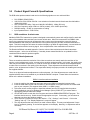
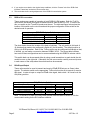
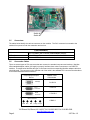
Installation/Operation Instructions
Fiber Optic RGB & DVI Video Transmission System
Part Numbers:
RGB-T-0 & RGB-R-0
(Single-channel, RGB / DVI Transmitter & Receiver)
Page 1
700 Elmont Rd, Elmont, NY 11003, Tel: 516-285-1000; Fax: 516-285-6300
www.Meridian-tech.com
3/07 Rev 1.2
Table of Contents
1.0
Product Description....................................................................................................................3
2.0
Installation ..................................................................................................................................3
2.1
3.0
Fiber connections...................................................................................................................3
Product Signal Format & Specifications.....................................................................................4
3.1
RGB resolutions & refresh rates.............................................................................................4
3.2
RGB Video Adjustments ........................................................................................................4
3.3
RGB to DVI conversion ..........................................................................................................5
3.4
RGsB Input/Output.................................................................................................................5
3.5
Connectors.............................................................................................................................6
3.6
Conversion Cables .................................................................................................................6
4.0
4.1
5.0
Front Panel Pinout Assignment Diagram ...................................................................................7
Status Indicators ....................................................................................................................7
Troubleshooting .........................................................................................................................8
Appendix 1 – Supported Video Resolutions & Refresh Rates ...............................................................8
Part Number Variations........................................................................................................................10
Page 2
700 Elmont Rd, Elmont, NY 11003, Tel: 516-285-1000; Fax: 516-285-6300
www.Meridian-tech.com
3/07 Rev 1.2
1.0
Product Description
Meridian’s RGB-T/R product is part of Meridian’s new DigiView product family. This state-of-the-art, high
performance video transmission system transmits fully-compliant DVI, RGsB or RGBHV signals over one,
multimode fiber. Optional DVI adapter cables allow easy interface to standard video connection interfaces on
computers, monitors, switches, etc. The RGB-T/R provides real-time, digitized transmission of DVI, RGB and
H&V sync signals. Because it transmits signals in real-time, no video information is lost and is a perfect solution
for dynamic video signals with crystal clear video and no color pixel skewing.
Having both DVI and RGB input/output capability, this system offers an easy upgrade path from RGB to DVI
systems with the same modules. With this dual input/output capability, the user can easily interface RGBHV
sources to DVI monitors and also DVI video sources to standard RGBHV monitors and video switches. The
user can further enhance the video performance with the use of the computer USB interface. This data channel
allows the user to adjust brightness, contrast, H&V position, picture sharpness, color, etc.
This product uses Meridian’s standard 1-slot wide chassis mount card assembly and plugs into the following
Meridian chassis: SR-500/S, SR-1000/S, SR-1200/S, SR-1500/S, and SR-2001 & SR-2000 series 19”
equipment chassis.
2.0
Installation
The RGB/DVI series products are one-slot wide cards and, as such, occupy one slot in Meridian’s standard
chassis (SR-500/S, SR-1000/S, SR-1200/S, SR-1500/S, and SR-2001 & SR-2000 series 19” equipment
chassis). To install in the chassis, orient the card with the Meridian logo at the top of the module and slide onto
the top and bottom card guides in the chassis. Press securely on the top and bottom of the module to ensure
that it is fully seated in the chassis so that the electrical connector mates with the chassis-mounted
motherboard. Once installed, manually tighten the two thumbscrews located at the top and bottom of the card.
Do not use tools to secure these and do not over tighten.
Note: A fully populated subrack should have forced-air cooling to avoid excessive heat buildup inside the
chassis. A fan assembly tray (P/N FA-2000/1) with three (3) fans is available from Meridian and should be
installed under the 19" SR-2000/1 whenever possible.
2.1
Fiber connections
There is one ST style fiber connection interface on the transmitter and a corresponding ST style fiber
connection on the receiver. These modems are designed for multimode fiber (either 62.5 or 50 micron core
diameter fiber). The maximum fiber distance is listed below:
Fiber type
62.5/125um
50/125um (standard performance)
50/125um (high bandwidth)
Maximum distance
300 meters
1000 meters
2000 meters
If the fiber distance is larger than that listed above, the video signal quality will be compromised and may not
operate properly.
Page 3
700 Elmont Rd, Elmont, NY 11003, Tel: 516-285-1000; Fax: 516-285-6300
www.Meridian-tech.com
3/07 Rev 1.2
3.0
Product Signal Format & Specifications
The RGB series products transmit and receive the following signals over one multimode fiber:
•
•
•
•
•
•
3.1
DVI, RGBHV, RGsB (YPbPr)
VGA, SVGA, SGA, SXGA & UXGA - Auto selection of resolutions and refresh rates from 640x480 to
1600x1200 x 60Hz
HDTV resolutions of 480p, 720p and 1080i (DVI & RGBHV), 1080p (DVI only)
H&V Sync frequency range of 60Hz to 150Hz (vertical), 30 to 130kHz (horizontal)
RGB processing – 24-bits, no compression or scaling
Input impedance/level – RGB 75ohm,
RGB resolutions & refresh rates
Meridian’s RGB-T/R-0 transmission system is designed to automatically sense and configure itself to work with
many of the standard video resolutions and screen refresh rates. When first connected to an RGBHV video
source, the transmitter/receiver pair will determine the incoming signal characteristics, search its internal
firmware database and modify the characteristics of the system to properly encode, transmit and decode the
signal. This initial recognition will cause the monitor’s display to go blank for approximately 1 second while the
system synchronizes with the incoming signal. Once completed the video transmission will continue.
The Resolution/Refresh rate table Appendix 1 lists the various video resolutions and refresh rates these
modules support – at the time of this writing. If needed, please contact Meridian for an updated list of the
resolutions/refresh rates this product supports.
3.2
RGB Video Adjustments
There are occasions where the resolution of the video source does not exactly match the resolution of the
monitor or minor adjustments in color, contrast, picture position need to be made. In this case, the quality of the
video may be somewhat compromised. In order to correct this, the RGB-T/R modules can be adjusted slightly
to make minor corrections in the quality of the video signal. These adjustments include Horizontal/Vertical
position, color, brightness and contrast. The steps below identify the proper procedure for installing and running
the supplied software.
There are no physical hardware adjustments on this equipment. All of the adjustments are made with the
supplied software that can be installed on your Windows 2000/XP computer. Please follow the instructions
below on the software installation.
RGB-HV Interface software installation
1. Insert the card into the chassis or card cage and turn the RGB-HV transmitter’s power supply
2. Insert the USB cable into the USB connector on the transmitter’s front panel and into an unused USB
port on your computer (This supports either USB1.1 or USB2.0 ports)
3. Follow the various screen prompts to install the software from the CD supplied with the product.
4. Once installed you can go to Windows Device Manager (Ports (COM & LPT)) to ensure that the
appropriate COM port has been installed
5. Click START button on task bar, then Programs and choose RGBCARDINTERFACE program. The
interface should come up. Select choose the appropriate com port. If necessary, you can select an
alternate port where the hardware resides.
6. There are three (3) tabs on the top of this window – “File”, “Settings”, and “Presets”. Click on the
“Settings” tab only. The “Display Adjustment” screen will appear.
7. The only adjustment that may need to be made is Phase Adjust. This may need adjustment if some
level of unwanted ‘ghosting’ or vertical bars appears on the display. Normally, no adjustments will be
necessary.
Page 4
700 Elmont Rd, Elmont, NY 11003, Tel: 516-285-1000; Fax: 516-285-6300
www.Meridian-tech.com
3/07 Rev 1.2
8. If you need to revert back to the original setup conditions, click the “Presets” tab of the ‘RGB Card
Interface Transmitter’ and select Current screen size.
9. This concludes the fine tuning adjustments of the RGB-HV transmission system
3.3
RGB to DVI conversion
These modems are capable of operating in both RGBHV & DVI modes. Both the Tx & Rx
units can be individually configured to transmit/receive either RGBHV or DVI. In order to do
this, one switch on the Tx and Rx boards must be set. The table and figure below show the
location of this switch on the circuit board and the proper configuration of the switch for the
desired mode of operation.
RGB/DVI Selector Switch
Mode (Tx or Rx)
RGB (In) - RGB (out) - Default
RGB (In) – DVI (out)
DVI (In) – RGB (out)
DVI (In) – DVI (out)
Tx Switch #1
OFF (up)
OFF (up)
ON (down)
ON (down)
Rx Switch #1
OFF (up)
ON (down)
OFF (up)
ON (down)
The photo below shows the location of the bank of switches. The only switch in this bank of
10 switches that needs to be configured is Switch #1 (far left switch). The default position is
ON (up) for RGB operation. Each of the Tx/Rx modules can be configured individually so that,
if desired, you can make a conversion between RGBHV & DVI. The above table indicates
how each of these configurations can be accommodated using this RGB/DVI selector switch.
This switch bank can be accessed either by using a small screwdriver to reach inside the slot
module’s cover on the right side. Otherwise, the side cover can be carefully removed (screws
in each corner of the card) where the switch can then be accessed.
3.4
RGsB Input/Output
These units can also be used to transmit and receive RGsB (RGB w/sync on Green) video
signals. The selector switch on the appropriate Tx/Rx units must be set to transmit or receive
this signal. In order to input or output an RGsB video signal, both switch 1 & 2 must be in the
ON (down) position.
RGsB Selector Switch
Mode (Tx or Rx)
RGB (In) - RGB (out) - Default
RGsB (In) – RGB (out)
RGB (In) – RGsB (out)
RGsB (In) – RGsB (out)
Transmitter (RGB-T-0)
Switch #1
Switch #2
OFF (up)
OFF (up)
OFF (up)
OFF (up)
OFF (up)
ON (down)
Off (up)
ON (down)
Receiver (RGB-R-0)
Switch #1 Switch #2
OFF (up)
OFF (up)
OFF (up)
OFF (up)
OFF (up)
OFF (up)
ON (down)
ON (down)
Note: To convert to or from DVI using RGsB, please follow the table in section 3.3 for the
correct switch setting for the DVI interface selection.
Page 5
700 Elmont Rd, Elmont, NY 11003, Tel: 516-285-1000; Fax: 516-285-6300
www.Meridian-tech.com
3/07 Rev 1.2
Switch #1
Switch #2
3.5
Connectors
The tables below identify the various connectors on the modules. The DVI-I connector is mounted to the
module’s front panel on both the transmitter and receiver.
Connectors
Video
Standard DVI-I female (with RGBHV analog inputs/outputs)
DVI-I to RGBHV (HD-15 female) molded adapter (dongle)
4-pin USB (type B)
Multimode - ST
RGB adjustment
Optical
3.6
Conversion Cables
There are several types of DVI connectors that are mounted on standard computers and monitors. Meridian
offers standard adapter cables (6 ft length) to properly interface these various connectors to our RGB-T/R
modules. The table below identifies the type of connectors and the corresponding Meridian adapter cable that
should be used. The connector on the opposite end of the cable is the standard DVI-I connector that interfaces
to the RGB transmitter/receiver modules.
Computer/Input/Output
Device
Adapter Cable
Part Number
HD15(M)
C-HD15-6
DVI-I
Connector
C-DVI-I-6
DVI-D
Connector
C-DVI-D-6
BNC Connectors
C-BNC-6
Red Grn
Page 6
Blu
H-Syn V-Syn
700 Elmont Rd, Elmont, NY 11003, Tel: 516-285-1000; Fax: 516-285-6300
www.Meridian-tech.com
3/07 Rev 1.2
4.0
Front Panel Pinout Assignment Diagram
Figure 4.1 below shows the front panel layout, connector location, indicator location and pinout assignment for
both the RGB-T and RGB-R modules. This diagram shows the video pinouts for the on-board DVI-I video
connector.
RGB/DVI-T
Pinout Diagram
RGB/DVI-R
Pinout Diagram
Figure 4.1
RGB-T-0 & RGB-R-0 Front Panel Layout Diagrams
4.1
Status Indicators
There are function status indicator lights associated these modules. They are identified as follows:
Power:
Diagnostic:
Tx Carrier (transmitter only):
Rx Carrier (receiver only):
DVI active:
RGB active:
SHV (sync H&V):
SOG (sync on green):
USB active:
Page 7
Green (ON)
Green (OK), Red (alarm)
Green (OK), Red (alarm)
Green (Present)/Red (Error)
Green
Green
Green (present)
Green (present)
Green (Rx-data), Red (Tx-data)
700 Elmont Rd, Elmont, NY 11003, Tel: 516-285-1000; Fax: 516-285-6300
www.Meridian-tech.com
3/07 Rev 1.2
5.0
Troubleshooting
Below is a listing of several problems that may arise during the installation & operation of the modules. If you
are having difficulty installing or operating the modules please refer to this list below.
Problem:
Action:
Problem:
Action:
Problem:
Action:
Module does not fit in chassis slots
Check module orientation. Meridian “Globe” must be oriented on the top left hand side of the
module
Make sure the card guides in the chassis are aligned with the extrusion on the module
Card power LED does not light when power to the module/subrack is applied or power indicator
turns on and off
Check power supply to ensure that it is plugged in and turned on. If flashing continues, move
module to another chassis or location in the same chassis, if available.
No Video
1 - Check the modem locations to ensure that the RGB-T module is connected to the video
source (computer, camera, etc) while the receiver module (RGB-R) is connected to the video
output device (monitor, etc.)
2 – Check to ensure that the modules are in the proper mode of operation (RGB or DVI) –
onboard switch #1 (see section 3.4)
If the problem still persists after reviewing the above items, please contact Meridian technical support (516-2851000).
Appendix 1 – Supported Video Resolutions & Refresh Rates
The table below lists the presently-supported video resolutions and refresh rates. Meridian continues to expand
the supported variations and will update this list as they become available.
If you have any questions about other resolution/refresh rates, please call our technical service personnel.
Page 8
700 Elmont Rd, Elmont, NY 11003, Tel: 516-285-1000; Fax: 516-285-6300
www.Meridian-tech.com
3/07 Rev 1.2
Video
Resolution
Horizontal
Frequency
(kHz)
Vertical
Frequency
(Hz)
640x480
640x480
640x480
640x480
640x480
640x480
640x480
640x480
640x480
640x480
640x480
640x480
31.47
35.16
37.86
37.50
43.27
50.90
61.80
72.92
75.00
78.30
90.6
108.0
60
70
72
75
85
100
120
140
144
150
170
200
800x600
800x600
800x600
800x600
800x600
800x600
800x600
800x600
800x600
800x600
800x600
800x600
37.88
43.81
48.08
46.88
53.67
63.60
77.16
90.74
94.10
98.23
112.5
134.5
60
70
72
74
85
100
120
140
144
150
170
200
1024x768
1024x768
1024x768
1024x768
1024x768
1024x768
1024x768
1024x768
1024x768
1024x768
1024x768
48.36
56.48
57.91
60.02
68.68
81.40
98.9
116.9
119.9
125.8
143.8
60
70
72
75
85
100
120
140
144
150
170
Page 9
Video
Resolution
Horizontal
Frequency
(kHz)
Vertical
Frequency
(Hz)
1152x864
1152x864
1152x864
1152x864
1152x864
1152x864
1152x864
1152x864
1152x864
1152x864
53.70
63.17
64.94
67.50
77.30
91.84
110.8
131.5
135.0
141.7
60
70
72
75
85
100
120
140
144
150
1280x720
1280x720
1280x720
1280x720
1280x720
1280x720
1280x720
1280x720
1280x720
1280x720
44.6
52.6
53.9
56.4
64.0
76.1
92.9
109.3
112.5
117.6
60
70
72
75
85
100
120
140
144
150
1280x960
1280x960
1280x960
1280x960
1280x960
1280x960
1280x960
60.0
70.0
71.9
75.0
85.9
101.4
123.1
60
70
72
75
85
100
120
1280x1024
1280x1024
1280x1024
1280x1024
1280x1024
1280x1024
64.0
74.7
76.9
80.0
91.2
108.0
60
70
72
75
85
100
1600x1200
75.0
60
700 Elmont Rd, Elmont, NY 11003, Tel: 516-285-1000; Fax: 516-285-6300
www.Meridian-tech.com
3/07 Rev 1.2
Part Number Variations
The table below indicates the part numbers and product description that are included in this manual.
Transmitter
Receiver
RGB-T-0M
RGB-T-0R
RGB-R-0M
RGB-R-0R
Description
RGBHV & DVI video transmitter/receiver pair, multimode, shelf mount
RGBHV & DVI video transmitter/receiver pair, multimode, rack mount
Note: Shelf mount (“M”) and rack mount (“R”) units can communicate with each other.
Page 10
700 Elmont Rd, Elmont, NY 11003, Tel: 516-285-1000; Fax: 516-285-6300
www.Meridian-tech.com
3/07 Rev 1.2