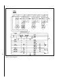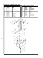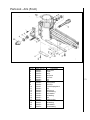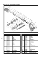
1
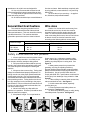
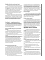
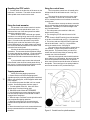
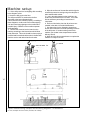
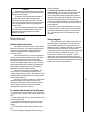
Radial Arm Drill Press
Model 1230
Operating instructions and parts manual
Part No. 9078241
Revision A
Table of Contents
Cover Page ........................................................................................................................ 1
General Specifications ...................................................................................................... 4
Operating Precautions ...................................................................................................... 5
Operating Instructions ....................................................................................................... 7
Lubrication and Coolant ................................................................................................ 13
Machine Set-up ............................................................................................................... 14
Wiring Diagram................................................................................................................. 16
Replacement Parts .......................................................................................................... 17
3
General specifications
The Wilton Model 1230 is a powerful and
versatile radial arm drill press. The drill head is
mounted on an arm and can move along the arm to
position the spindle over the work piece. The arm,
itself, can be rotated on its support column to allow
centering the spindle over the work piece.
Drilling can be performed manually or with
power assistance. In addition, parameters of RPM,
power feed rate and drilling depth can be pre-set by
the operator, using controls conveniently positioned
on the drill head, to allow any hole to be drilled using
power feed.
A precision machined box table is delivered with
the Model 1230 to allow convenient positioning and
clamping of smaller work pieces. The box table may
be removed from the base to allow larger workpieces
to be positioned and clamped on the precision
machined base, itself.
Machining capacities
Steel
Cast iron
Drilling
2 1/8 in. (53mm)
2 1/2 in. (63mm)
Tapping
1 1/8 in. (28mm)
1 3/4 in. (44mm)
Boring
3 3/8 in. (84mm)
4 3/4 in. (119mm)
Overall dimensions and specifications
4
Column diameter
Column to spindle center distance, max.
Column to spindle center distance, min.
Spindle travel along arm, total
Base surface to spindle end, max. (no tooling)
Base surface to spindle end, min. (no tooling)
Quill (spindle) travel
Arm movement range on support column
Box table dimensions
Base dimension
Spindle taper
Spindle speeds, RPM
Feed rates (distance/revolution)
Main motor HP
Arm raising motor HP
Clamping motor
Coolant pump motor HP
Machine height (floor to max.)
Net weight (approx)
11 13/16 in. (295mm)
46 in. (1150mm)
13 3/8 in. (334mm)
35 in. (875mm)
54 in. (1350.0mm)
19 3/8 in. (484mm)
9 7/8 in. (247mm)
34 5/8 in. (866mm)
27 7/8 x 20 1/2 x 16 1/2 in.
(697x513x413mm)
67 3/4 x 25 15/16 x 6 1/2 in.
(1694x648x163mm)
Morse #4
45-1550
0.002, 0.004, 0.006 in/rev
(0.005, 0.010, 0.030 mm/rev)
5
1
1
1/8
109 1/2 in. (2,738mm)
4,620 lb. (2,100 kg)
- Misuse of this machine can cause serious injury.
- For safety, machine must be set up, used and
serviced properly.
- Read, understand and follow instructions in the
operator’s and parts manual which was shipped with
your machine.
When setting up machine:
- Always avoid using machine in damp or poorly
lighted work areas.
- Always be sure machine is securely anchored to
the floor.
- Always keep machine guards in place.
- Always put start switch in “OFF” position before
plugging in machine.
When using machine:
-Never operate with machine guards missing.
-Always wear safety glasses with side shields (See
ANSI Z87.1)
-Never wear loose clothing or jewelry.
-Never overreach — you may slip and fall into the
machine.
-Never leave machine running while you are away
from it.
-Always shut off the machine when not in use.
When servicing machine:
-Always unplug machine from electrical power while
servicing.
-Always follow instructions in operators and parts
manual when changing accessory tools or parts.
-Never modify the machine without consulting Wilton
Corporation.
You — the stationary power tool user — hold the key
to safety.
Read and follow these simple rules for best results
and full benefits from your machine. Used properly,
Wilton’s machinery is among the best in design and
safety. However, any machine used improperly can
be rendered inefficient and unsafe. It is absolutely
mandatory that those who use our products be
properly trained in how to use them correctly. They
should read and understand the Operators and Parts
Manual as well as all labels affixed to the machine.
Failure in following all of these warnings can cause
serious injuries.
Machinery general safety warnings
1. Always wear protective eye wear when
operating machinery. Eye wear shall be impact
resistant, protective safety glasses with side shields
which comply with ANSI Z87.1 specifications. Use of
eye wear which does not comply with ANSI Z87.1
specifications could result in severe injury from
breakage of eye protection.
2. Wear proper apparel. No loose clothing or
jewelry which can get caught in moving parts.
Rubber soled footwear is recommended for best
footing.
3. Do not overreach. Failure to maintain
proper working position can cause you to fall into the
machine or cause your clothing to get caught —
pulling you into the machine.
4. Keep guards in place and in proper working
order. Do not operate the machine with guards
removed.
5. Avoid dangerous working environments. Do
not use stationary machine tools in wet or damp
locations. Keep work areas clean and well lit.
Special electrics should be used when working on
flammable materials.
6. Avoid accidental starts by being sure the start
switch is “OFF” before plugging in the machine.
7. Never leave the machine running while
unattended. Machine shall be shut off whenever it is
not in operation.
8. Disconnect electrical power before servicing.
Whenever changing accessories or general maintenance is done on the machine, electrical power to the
machine must be disconnected before work is done.
9. Maintain all machine tools with care. Follow
all maintenance instructions for lubricating and the
changing of accessories. No attempt shall be made
to modify or have makeshift repairs done to the
machine. This not only voids the warranty but also
renders the machine unsafe.
10. Machinery must be anchored to the floor.
11. Secure work. Use clamps or a vise to hold
work, when practical. It is safer than using your
hands and it frees both hands to operate the machine.
12. Never brush away chips while the machine
is in operation.
13. Keep work area clean. Cluttered areas
invite accidents.
14. Remove adjusting keys and wrenches
before turning machine on.
15. Use the right tool. Don’t force a tool or
5
attachment to do a job it was not designed for.
16. Use only recommended accessories and
follow manufacturers instructions pertaining to them.
17. Keep hands in sight and clear of all moving
parts and cutting surfaces.
18. All visitors should be kept at a safe distance
from the work area. Make workshop completely safe
by using padlocks, master switches, or by removing
starter keys.
19. Know the tool you are using — its application, limitations, and potential hazards.
General Electrical Cautions
Wire sizes
Caution: for circuits which are far away from
the electrical service box, the wire size must be
increased in order to deliver ample voltage to the
motor. To minimize power losses and to prevent
motor overheating and burnout, the use of wire sizes
for branch circuits or electrical extension cords
according to the following table is recommended:
AWG (American wire gauge) number
240 volt lines
120 volt lines
No. 14
No. 14
No. 14
No. 12
No. 12
No. 8
This machine should be grounded in accordance with the National Electrical Code and local
codes and ordinances. This work should be done by
a qualified electrician. The machine should be
grounded to protect the user from electrical shock.
Conductor length
0-50 feet
50-100 feet
Over 100 feet
Safety instructions on drill presses
6
1. All work shall be secured using either clamps
or a vise to the drill press table. It is unsafe to use
your hands to hold any workpiece being drilled.
2. Drill press head and table shall be securely
locked to the column before operating the drill press.
This must always be checked prior to starting the
machine.
3. Always use the correct tooling. Tooling shall
always be maintained and properly sharpened. All
tooling must be run at the proper speeds and feeds
as they apply to the job. Use only recommended
accessories and follow those manufacturers instructions pertaining to them. Tooling shall not be forced
in to any workpiece but fed according to the proper
specifications. Failure to follow these instructions will
not only ruin the tooling as well as the machine, but
can cause serious injury.
4. Never brush away any chips while the
machine is in operation. All clean up should be done
when the machine is stopped.
5. Keep hands in sight. Do not put hands or
fingers around, on, or below any rotating cutting
tools. Leather safety gloves should be used when
handling any sharp objects or cutting tools. See
Figure A.
6. Always wear protective eye wear when
operating, servicing or adjusting machinery.
Eyewear shall be impact resistant, protective safety
glasses with side shields complying with ANSI Z87.1
specifications. Use of eye wear which does not
comply with ANSI Z87.1 specifications could result in
severe injury from breakage of eye protection. See
figure B.
7. When drilling in material which causes dust,
a dust mask shall be work. See Figure C.
8. Avoid contact with coolant, especially
guarding the eyes.
9. Non-slip footwear and safety shoes are
recommended. See figure D.
12. Wear ear protectors (plugs or muffs) during
extended periods of operation. See figure E.
Operating Instructions
Clamping workpieces to the machine
Both the box table and the base surface are
slotted to accept a suitably sized T-slot clamp.
Before begining any work on the drill press, anchor
the work piece, and the box table, too, if used, to be
certain the workpiece and/or box table will not move
when the drill, tap or boring tool enters the
workpiece.
Caution
Failure to properly anchor the workpiece
and box table could result in damage to the
machine, damage to the workpiece, and worse -severe injury and possibly death to the machine
operator. Never work on the drill press without
clamping the materials using a T-slot system setup.
Figure 1: Drill press nomenclature
7
Inserting tooling
The Model 1230 uses a #4 Morse taper in the
spindle to secure tooling. Any drill, milling cutter, or
tool holder with a #4MT can be inserted into the quill.
Caution
The first step in removing or inserting any
tooling is to be absolutely certain the machine
cannot be accidentally started during the insertion
or removal operation. The only way to be certain
of this fact is to disconnect power to the machine
using the service box cut-out switch. The service
box (typically the one holding the fuses or circuit
breakers will have been installed by the electrician
who connected the machine to its service branch)
should have a cut-out switch or lever on the outside
of the box. Put the switch or lever in the OFF
position before inserting or removing tooling.
To insert tooling:
1. Observe the caution, above, and be certain all
power to the machine has been disconnected.
2. Be certain the spindle is clean, free from oil, and
ready to accept the shank of any tooling.
3. Check the shank of the tooling to be certain the
tooling is free from dirt, nicks or burrs. If any nicks
or burrs are discovered, file and/or stone the shank
until the shank is smooth.
4. Be certain the quill is in the full UP position.
5. Slide the shank of the tooling into the spindle until
it seats.
6. Use a soft-faced mallet (such as lead, plastic,
brass, etc.) to give the tooling a sharp tap on its tip.
This will secure the tooling firmly in the taper.
7. Re-establish power to the machine and the drill is
ready to use.
8
To remove tooling:
1. Observe the caution above and be certain all
electrical power to the drill press has been cut off.
2. Place a wood block under the tooling in the
spindle to prevent it from being damaged, should it
fall out of the quill during the removal process.
3. Lower the quill by using the feed levers until the
tool removal window is exposed.
4. Using a suitable tapered drift, insert the drift in
the removal window, above the tip of the tooling
shank.
5. Using leather gloves to prevent cuts from the
tooling, hold the tooling with you hand to prevent it
from falling from the quill.
6. With your free hand, using a hammer, tap the
tapered drift and the tooling will loosen from the taper
and can be removed. The spindle is now ready for
the insertion of other tooling with a #4 MT.
Positioning the tooling over the
workpiece.
After the workpiece has been clamped to the
base or table you can position the tooling over the
workpiece by doing any or all of the following:
1. Adjusting the height of the arm on the support
column.
2. Moving the drill head along the arm.
3. Rotating the column upon which the arm and head
are attached.
Unlocking the arm and column
mechanisms
A motorized locking system is used to lock the
head to the arm, the arm to the column, and the
column to the base.
The lock and unlock buttons which control the
locks are located on the right-hand side of the drill
head. When you push UNLOCK, all of the locks are
unlocked. When you push LOCK, all of the locks are
locked.
Caution
Always be certain the locks are engaged before
using the drill press. Pull on the arm handle and
try to rotate the head locating wheel before
pushing the spindle ON button. Failure to have
all locks locked may result in damage to tooling,
damage to the work piece, and possible injury to
the operator.
Raising and lowering the radial arm
1. Power to the drill press must be ON -- then release
the machine locks by pushing the UNLOCK push
button.
2. Use the control lever -- push it upward or downward as required -- (see Fig. 3) to raise or lower the
arm to the required height. See also, Using the
control lever.
3. When the arm is at the required height and if no
other adjustments to spindle location are required,
push the LOCK push button to re-lock all machine
locks.
To move the drill head along the arm
1. Power to the drill press must be ON -- then release
the machine locks by pushing the UNLOCK push
button.
2. Using the wheel in the center of the drill head, turn
the wheel to move the drill head along the arm. (See
Fig. 1.)
3. When the drill head is at the desired position on
the arm and if no other adjustments to spindle location
are required, push the LOCK push button to re-lock all
machine locks.
CAUTION
NEVER swing the drill press arm using the
support column unless you are absolutely certain
the drill press base is firmly attached to the shop
floor. You can tell if the base is bolted to the floor
by checking the mounting pads at the four corners
of the base. There should be a securing bolt
through each mounting pad.
If the arm is moved off of its position directly
above the base and the base is not bolted to the
floor, THE DRILL MAY TIP OVER AND CAUSE
SERIOUS INJURY OR DEATH TO THE DRILL
PRESS OPERATOR (YOU!!) and will certainly
result in serious damage to the drill press, itself.
Don't take chances. Always look for bolts at the
mounting pads before swinging the drill press arm.
Moving the arm on the support column
1. Power to the drill press must be ON -- then
release the machine locks by pushing the UNLOCK
push button.
2. Use the handle at the end of the arm (see Fig. 1)
to move the column (and, therefore, to swing the arm)
as necessary to the required spindle position.
3. When the spindle is positioned correctly and no
other adjustments are quired, push the LOCK push
button to re-lock all machine locks.
on LOW or HI speed. There is a chart on the front of
the drill head which shows you the spindle speeds
available and the gear change lever and motor switch
values required to select each speed. See Fig. 1.
On the gear change table you will also find the
recommended drill sizes for the various speeds which
are selectable. THESE RECOMMENDATIONS ARE
ONLY APPROXIMATE. With the wide variety of drill
types and coatings available, the variety of cutting
fluids which might be used, and the even wider
variety of work piece materials which you might be
machining -- you need to consult with your tooling,
coolant and/or work piece suppliers to determine the
best spindle speed to use for any specific drilling
operation.
Caution
Do not try to change gears while the spindle
is turning. This may cause serious damage to the
spindle drive system.
Allow the spindle to come to a complete stop
before attempting to change gears. If the gear
change lever you want to move does not slip
easily into the new position you require, jog the
motor for a second using the control lever. Then
allow the spindle to come to a stop again before
attempting to change gears, again. Repeat this
jogging process, as necessary, until the gears
match up properly for changing.
Setting spindle speed
Spindle speeds are established using the gear
change levers on the upper right-hand side of the drill
head. (See Fig. 1.) The shorter of the two levers
operates a two-speed mechanism which puts the
gearbox in either high gear or low gear. There is a
"HI/LOW" readout on the upper left hand side of the
drill head which tells you which speed range is
selected.
The longer gear change lever operates a three
speed gearbox mechanism. The lowest gear and
spindle speed is selected by pushing the lever away
from you -- that is, by rotating the change shaft
counterclockwise. The highest gear and spindle
speed is selected by pulling the lever toward you -rotating the shaft clockwise. There is a detent in the
middle of the lever travel to tell you when the lever is
in the intermediate gear position.
This gearbox set-up gives you a total of six
spindle speeds which may be selected. The twospeed spindle drive motor, therefore, increases the
number of available spindle speeds to 12. The
specific spindle speed selected clearly depends on
the position of both gear change levers and whether
the motor switch on the top front of the drill head is
Setting feed rate and depth of cut
The Model 1230 has limit switches on the quill
which cuts off electric power to the drive motor when
the quill has reached either the upper or lower limit of
its travel. This system is designed to prevent gearbox
damage if the power feed mechanism is engaged -damage which would occur if the quill were to bottom
out against the upper or lower limit of quill travel. In
the event of failure of either limit switch there is also a
safety clutch mechanism which will slip when the
limits of travel are reached.
However, while you are able to use virtually the
full travel of the quill for drilling or other operations,
the drill press operator typically sets both the rate of
feed -- travel-per-revolution of the spindle -- and the
depth of cut -- that is, the total distance the quill
moves to make the required depth of cut.
These two operations are described, here:
Setting feed rate
The feed rate is set using the knob and dial on
the front of the drill head. See Fig. 1. The knob on
the dial can be rotated to select any of three different
9
feed rates, plus a neutral position where the power
feed does not operate on the quill.
It is recommended that when doing operations
which do not require power feed that the dial be set to
the neutral position. This minimizes any wear on the
power feed mechanism.
The feed rate selected is indicated by a pair of
rivet heads on the edge of the rate setting dial. These
values are indicated on the far outer edge of the
readout.
Clearly, whenever the indicator rivets are at an
"N" position, no feed or "neutral" has been selected.
Any of the three feed rates are available for
selection using any of the spindle speeds available.
There will be a recommended feed rate for any
drilling or boring operation, and this rate must be
determined by consulting appropriate machining
handbooks or by consulting with your tooling, coolant
and work piece suppliers.
Setting depth of cut using the power
feed system
There is a mechanism for engaging the power
feed and there is also a mechanism (a "trip mechanism) which can be set to disengage the power feed
when a pre-set depth has been reached.
The feed levers can be pulled outward -- or
pushed inward -- on pivots which are in the feed lever
hub. When the feed levers are pushed toward the
drill head, the power feed mechanism is disengaged.
When the feed levers are pulled outward, the power
feed system is engaged. In the power feed position
(outward) the quill and spindle will be driven EITHER
until they reach the limit of travel and the limit
switches cut off power -- OR until the trip mechanism
disengages the power feed, automatically -- OR until
the drill press operator pushes the feed levers into the
disengaged position.
To set the depth of cut
1. Unlock lever A -- See Fig. 2.
2. Use the feed levers to lower the drill until it touches
the work piece.
3. Rotate the dial D until the rivet on the dial -- C -- is
at the feed depth required on the scale on graduated
dial B.
4. Lock lever A.
5. Pull the feed levers out to engage the power feed
clutch.
Note: Because the ring for Dial B makes one
rotation before contacting the mechanical trip dog,
you are limited to 4 inches (100mm) of travel during
any power feed operation. If you need to make
deeper holes you will need to do the machining in
steps.
10
Figure 2: Power feed controls
Spindle direction and power feed
The spindle can be driven clockwise or counterclockwise. The direction of rotation is controlled by
the control lever on the left hand side of the drill head.
See Fig. 1.
Clockwise or "forward" rotation is the direction
of rotation for right-hand tooling -- which is the vast
majority of tooling used in machine operations.
However, if you use left-hand tooling for any operations, the spindle direction can be set to counterclockwise or "reverse."
The power feed direction is determined by the
spindle direction. When the spindle is set to its most
common direction -- clockwise or forward -- the quill
and spindle are driven downward. When the spindle
direction is set to counterclockwise or reverse
direction, the quill and spindle are driven upward.
Hand feed -- roughing operations
When the feed levers are pushed toward the
drill head the power feed mechanism is disengaged.
In this position, the feed levers can be used to move
the quill and spindle and perform manual drilling or
other machining operations.
Fine hand feed using the power feed
system
The fine feed control wheel is located on the
underside of the right-hand side of the drill head.
See Fig. 1. The fine feed control is used as follows:
1. Set the feed rate dial to N -- neutral.
2. Pull the feed levers out so the power feed clutch is
engaged.
3. Turn the drill press POWER switch ON and set the
control lever so the spindle is turning in the correct
direction for the operation you are performing.
4. Turn the fine feed control wheel by hand. The
quill and spindle will move downward or upward
(depending upon which way you turn the wheel and
the direction the spindle is turning) until you stop
turning the control wheel.
Power ON and power OFF
If your Model 1230 was connected to its service
branch correctly, there will be a service disconnect
with an external power cutoff lever or switch which
disconnects the drill press from the service branch.
This is your ultimate protection against accidental
machine start-up when clamping work pieces to the
machine and/or inserting or removing tooling. Always
be certain you have turned off power at this disconnect before doing these operations.
Once your workpiece is clamped securely and
the tooling is installed, you can restablish power to
the machine by turning the cut-out panel back ON.
This will reestablish power to the machine control
system and will allow you to use the motor which
raises and lowers the arm to position the tooling over
the work piece. Raising and lowering of the arm is
controlled by the control stick -- see Fig. 3 and read
page 7, Raising and lowering the radial arm.
Power ON light
When the cutout box power is ON, the POWER
light on the upper left hand side of the drill head (Fig.
1) will be lit. In this mode, power to the coolant pump
and to the spindle drive motor is controlled by the
switches on the control console.
Flood coolant control
The flood coolant system provided with the drill
press is turned on by turning the switch to the ON
position. Power OFF to the coolant pump is achieved
by turning the switch counterclockwise to its OFF
position. (If coolant does not flow, check the pump
rotation by observing the pump shaft. It should be
rotating in the direction of the arrow on the pump
casting. If it is not rotating in the correct direction,
see Electrical, for more information.)
Spindle motor controls
The power to the spindle motor controlled as
follows:
1. The cutout box control lever must be in the ON
position so power is being fed to the drill press.
2. The two speed spindle drive motor switch must be
in either HI or LOW position.
3. The control ON/OFF switch must be pushed ON.
4. The arm/spindle control lever must be pulled
forward (clockwise rotation) or backward (counterclockwise rotation.) See Using the control lever,
page 11.
Turning spindle drive motor power OFF
To turn power OFF on the spindle drive motor do
one of the following:
1. Put the two speed motor switch in OFF position,
OR...
2. Push the Control ON/OFF switch off, OR...
3. Put the arm/spindle control lever in its middle
(neutral) position, OR...
4. Push the large, red emergency off STOP switch,
OR...
5. When servicing the tooling or other machine
components, put the service disconnect lever in OFF
position.
Once the STOP switch has been pushed (4.,
above) none of the other switches on the panel can
be used to control power to the spindle drive motor or
coolant pump until the STOP switch has been re-set.
11
Resetting the STOP switch
Using the control lever
1. Turn the switch in the direction of the arrow on the
red button -- clockwise. The switch is reset and the
other spindle motor controls can be used.
The four-position control lever is located on the
left hand side of the drill head console. See Figs. 1
and 3.
The control lever can move up or down, backward or forward, or can be left in its most central,
OFF or neutral position so no functions are under its
control power.
The control lever moves up or down to move the
arm up or down when positioning the tooling over the
work piece. This ability to control the height of the
arm is available when:
1. The main power to the machine is ON at its
branch service panel.
2. The emergency STOP switch is set to its ON
mode.
3. The Control ON/OFF switch (lower left hand side
of the face of the drill head, see Fig. 1) pushed ON.
4. The column and arm UNLOCK button (right hand
side of the drill head -- see Fig. 1) is pressed to
unlock the machine locks. See page 6.
The control lever does not return to neutral when
it is released. It stays in the position in which you
have placed it. This means unless you return it to
neutral, the arm will keep raising or lowering until it
contacts one of its limit switches.
When the motor speed control switch has been
set to either HI or LOW position, the control lever can
be moved backward or forward to turn the spindle
drive motor ON and control the direction of rotation of
the spindle. The control lever is not spring loaded to
return to the neutral or OFF position when you
Using the load ammeter
An ammeter on the control console is used to
monitor the load on the spindle drive motor. It is
connected into one of the three power lines which
supply the main drive motor.
When the drive motor is ON and up to speed,
and there is no tooling being used to drill, tap or bore
a hole, the ammeter should read approximately 2.5
amps. If it is above this value there is a problem
internally (such as lack of lubrication in the gearboxes, bad bearings, etc.) which means you should
turn off the machine and determine the cause of the
excessive free-running load.
Monitor the the ammeter during machining
operations. The ammeter should stay below 9 amps
or current draw during machining. You should adjust
your spindle speed, feed rate and coolant use to
maintain the full load current draw below the 9 amp
value.
If you exceed 9 amps current draw a thermal
limiter switch in the electrical control panel will trip. If
this occurs, a licensed electrician should be used to
locate and re-set the thermal limiter switch.
Tapping operations
12
When performing tapping operations :
1. Determine the most efficient tapping speed
(spindle speed) by consulting appropriate machinist's
tables, your tap supplier, coolant supplier and/or work
piece supplier.
2. Be certain the power feed dial is in N or neutral
position. See Setting power feed rate, page 8.
3. Turn the spindle motor ON. Also, turn on the
coolant pump if coolant is being used.
4. Move the control lever to FORWARD.
5. Use the feed levers to move the tap into its pilot
hole until the tap makes its initial thread cut and is
engaged in the workpiece.
6. Allow the tap to "self feed" into the pilot hole until it
has completed its tapping operation.
7. Move the control lever into its center/neutral
position until the spindle has come to a complete
stop.
8. Move the control lever into its reverse direction so
the tap unscrews itself from the hole it has just
threaded.
Figure 3: Control lever for spindle and arm.
release it. Rather, the lever stays in the position in
which you put it when you are controlling the spindle.
There is no need to hold it in position to keep the
spindle running.
All of these functions are clearly labeled on the
plate which surrounds the control lever and boot.
Periodic maintenance
The only maintenance for the Model 1230 is
lubrication and changing of the coolant according to
the schedule, below.
Item
Oiling cup
Oiling cup
Oiling cups
Arm raising
worm
Sight glass
Location
Top and bottom of arm
at column
Top of drill head
Right hand side of
drill head
Rear of column
On drill head
Lift chains
Ways
Coolant
On rear of arm
On arm
In tank
Oil fitting
Rack
On quill
On arm
Action
Add lubricant with lube gun
Interval
Daily
Lubricant
Mobil Vactra oil AA
Add lubricant with lube gun
Add lubricant with lube gun
Daily
Daily
Mobil Vactra oil AA
Mobil Vactra oil AA
Oil using lube gun
Daily
Mobil Vactra oil AA
Check for level -- fill through
pipe plug hole top of drill head
Lubricate with lube gun
Lubricate with lube gun
Monitor for cleanliness
and efficiency. Replace when
dirty or when cutting becomes
inefficient
Lubricate with gun
Lubricate with gun
Daily
Mobil Vactra oil AA
Weekly
Twice daily
When cutting
Mobil Vactra oil AA
Mobil Vactra oil AA
Daily
Every 3 days
Mobil Vactra oil AA
Mobil Vactra oil AA
13
Figure 4: Lubrication diagram
Machine set-up
1. Lift the drill press from its shipping skid according
to the diagram, below.
2. Secure the drill press to the floor
The drill press MUST be anchored to the floor
according to the layout diagram below.
Failure to anchor the machine properly, according to
these diagrams, could result in the machine tipping
over and consequent damage to the machine and
possible injury or DEATH to the machine operator
and bystanders.
3. Connect the electrical service branch to the
machine according to the instructions which follow
under Electrical. This work should be done only by a
qualified and licensed electrician who is familiar with
machine service and national and local codes.
4. Wipe the surfaces of the machine which might be
coated with protective coating using mineral spirits or
other nonflammable solvent.
5. Look in the sight glasses on the machine to be
certain they are filled to their level lines. If low, add
fluid as necessary according to instructions in
Lubrication.
6. Perform a lubrication check at all points recommended in the table in Periodic Maintenance.
7. Use instructions in the Operating Instructions
section of this manual to check all operating functions
of the drill press. If coolant is being used in this
machine, put coolant in the sump and test coolant
delivery, as well.
8. When all of the above operations are complete the
machine is ready for service.
14
Figure 5: Machine lifting, transport and anchoring diagrams -- all dimensions
in mm, except anchor bolts (inches, as noted)
Caution
Electrical set-up should be performed only by
a licensed electrician who is familiar with national
and local electrical codes.
The Model 1230 is shipped after testing all
functions and circuits under electrical power
specified for the machine and motors. The only
hook-up requirement should be for correct connection to an appropriate cutout on an appropriate
service branch.
Where the following instructions do not agree
with local electrical codes and procedures, the
applicable codes and procedures should be
followed, exclusively.
Electrical
Electrical branch service
The machine is wired for either a 230 or 460 3phase service branch. The cable supplying the drill
press will be tagged with the voltage at which the
machine was tested and corresponding to the
customer's order.
If the tag has been lost, it will be necessary for
you to open the electrical cabinet on the rear of the
drill press and examine the connections on the
transformer found inside the box. The transformer
can be connected to either a 230 or 460 volt source
and its taps are labeled for voltage. By locating the
source tap on the transformer you will be able to
determine the branch voltage required.
A service disconnect is recommended. The
use of fuses or circuit breakers for each of the
voltage supply wires is required. Use fuses or circuit
breakers which are appropriate to the voltage for the
motor system delivered.
A positive cut-out/lock-out lever or rocker switch
should be located on the outside of the service
disconnect to allow the machine operator to disconnect the machine from the branch circuit when
working with tooling on the machine.
To connect the branch to the drill press
1. Disconnect the service branch to the machine by
moving the lever or rocker switch on the cutout box to
OFF.
2 Connect the green wire (or green with white trace)
to the branch ground.
3. Connect the remaining three wires in the cable
(labeled R,S and T) to the three power lines in the
branch.
4. Turn the power to the machine ON at the cutout
box.
5. Turn the coolant pump power switch (See Fig. 1)
to the ON position.
6. Observe the direction of rotation of the
coolant pump. You can see the pump shaft rotate
on top of the pump at the rear of the drill press.
There will be an arrow cast into the pump, and the
shaft should be rotating in the direction of the arrow.
If the shaft is rotating in the wrong direction, the
power is connected, backwards. Correct as follows:
7. Disconnect power to the machine by turning it off
at the cutout box.
8. Reverse any two of the power lead connections.
9. Repeat steps 4, 5, and 6, above, and you should
observe the pump shaft turning in the correct direction. The electrical service to the machine is now
complete.
Wiring diagram
A wiring diagram for the drill press is found on
the facing page. This diagram is for reference by
your licensed installing or servicing electrician. In
addition to using a licensed electrician for connection
to the drill press service branch, the servicing of
components and circuits inside the control box should
be serviced only by a qualified electrician. This
includes fuse replacement, if required. If any of
these fuses, upon replacement, should continue to
fail at short service intervals, the electrician should be
asked to check all machine components for excessive
loads, short circuits or other failures.
15
16
Figure 6: Wiring diagram
Replacement Parts
This section provides exploded view illustrations that show the replacement parts for the Wilton 4 foot arm,
Model 1230 Radial Drill. Also provided are parts listings that provide part number, description, and quantity.
The item numbers shown on the illustration relate to the item number on the facing page of the parts listing.
Order replacement parts from:
Wilton Corporation
300 South Hicks Road
Palatine, IL 60067
TEL: 1-888-594-5866
FAX: 1-800-626-9676
Identify the replacement part by the part number shown in the parts listing. Be sure to include the model number
and serial number of your machine when ordering replacement parts to assure that you will receive the correct
part.
17
Exploded View - Column and Base
18
Parts List - Column and Base
Ref no. Wilton part no.
1
2
3
4
5
6
7
8
9
10
11
12
13
14
15
16
17
18
19
20
21
22
23
24
25
26
27
28
29
30
31
32
33
34
35
5232911
5232921
5232931
5232941
5232951
5232961
5232971
5232981
5232991
5233011
5233021
5233031
5233041
5233051
5233061
5233071
5233081
5233091
5233111
5233121
5233131
5233141
5233151
5233161
5233171
5233181
5233191
5233211
5233221
5233231
5233241
5233251
5233261
5233271
5233281
Description
Base
Bolt
Needle bearing
Internal column
Bolt
Top bearing cover
Thrust bearing
Fixed brg. housing
Thrust bearing
Washer
Ball bearing
Top bearing cover
External column
Slip blocket
Retaining ring
Slip bar
Fixing shaft
Retaining ring
Nut
Roller
Wedge
Key
Elevating shaft
Screw
Roller
Ship blocket
Slip bar
Shaft
Bushing
Locking blocket
Bolt
Key
Clamping gear
Locking shaft
Locking cover
19
Parts List - Column Gear Box
Ref no.
1
2
3
4
5
6
7
8
9
10
11
12
20
Wilton part no.
5235751
5235761
5235771
5235781
5235791
5235811
5235821
5235831
5235841
5235851
5235861
5235871
Description
Bolt
Washer
Bushing
Round bar
Plain washer
Nut
Nut
Bolt
Chain frame
Screw
Limit switch
Retaining ring
Ref no. Wilton part no.
13
14
15
16
17
18
19
20
21
22
23
5235881
5235891
5235911
5235921
5235931
5235941
5235951
5235961
5235971
5235981
5235991
Description
Needle bearing
Shaft
Retaining ring
Retaining ring
Needle bearing
Shaft
Retaining ring
Chain
Bolt
Chain adapter
Cast iron block
Parts List - Arm (Front)
Ref no. Wilton part no.
1
5233311
2
5233321
3
5233331
4
5233341
5
5233351
6
5233361
7
5233371
8
5233381
9
5233391
10
5233411
11
5233421
12
5233431
13
5233441
14
5233451
15
5233461
16
5233471
17
5233481
18
5233491
19
5233511
20
5233521
21
5233531
Description
Lamp cover
Screw
Lamp
Lamp seat
Arm rack
Bolt
Arm
Locking shaft
Oil fill cup
Fixed clamping block
Bolt
Locking nut
Thrust bearing
Plain washer
Ball bearing
Bolt
Aluminum ring
Screw
Ball bearing
Plain washer
Thrust bearing
21
Exploded View - Arm (Rear)
22
Parts List - Arm (Rear)
Ref no. Wilton part no.
1
2
3
4
5
6
7
8
9
10
11
12
13
14
15
16
17
18
19
20
21
22
23
24
25
26
27
28
29
30
31
32
33
34
35
36
37
38
39
40
41
42
43
44
45
46
47
48
49
5236011
5236021
5236031
5236041
5236051
5236061
5236071
5236081
5236091
5236111
5236121
5236131
5236141
5236151
5236161
5236171
5236181
5236191
5236211
5236221
5236231
5236241
5236251
5236261
5236271
5236281
5236291
5236311
5236321
5236331
5236341
5236351
5236361
5236371
5236381
5236391
5236411
5236421
5236431
5236441
5236451
5236461
5236471
5236481
5236491
5236511
5236521
5236531
5236541
Description
Motor
Gear
Key
Bolt
Pin
Bolt
Upper cover
Taper bearing
Gear
Washer
Bolt
Gear case cover
Gear case
Worm shaft
Taper bearing
Retaining ring
Cover
Bolt
Key
Bushing
Cover
Bolt
Oil cup
Locking shaft
Bushing
Bolt
Bushing
Block
Arm
Gear
Bolt
Retaining ring
Cover
Bearing
Shaft
Worm gear
Plain washer
Bolt
Bearing
Bushing
Bolt
Gear
Ke
Bolt
Block
Bolt
Key
Shaft
Key
Ref no. Wilton part no.
50
51
52
53
54
55
56
57
58
59
60
61
62
63
64
65
66
67
68
69
70
71
72
73
74
75
76
5236551
5236561
5236571
5236581
5236591
5236611
5236621
5236631
5236641
5236651
5236661
5236671
5236681
5236691
5236711
5236721
5236731
5236741
5236751
5236761
5236771
5236781
5236791
5236811
5236821
5236831
5236841
Description
Bolt
Gear
Block
Block
Bolt
Rack shaft
Rack
Bolt
Block
Shaft
Gearbox
Bushing
Shaft
Key
Retaining ring
Retaining ring
Bushing
Bushing
Bushing
Retaining ring
Gear
Gear
Bolt
Bolt
Gear
Bolt
Rubber tap
23
Parts List - Riser Mechanism
Ref no. Wilton part no.
24
1
2
3
4
5
6
7
8
9
10
11
12
13
14
15
16
17
18
19
20
5232451
5232461
5232471
5232481
5232491
5232511
5232521
5232531
5232541
5232551
5232561
5232571
5232581
5232591
5232611
5232621
5232631
5232641
5232651
5232661
Description
Motor
Key
Screw
Adapter
Plastic sheet
Screw
Adapter
Bolt
Cover
Oil seal
Bearing
Key
Key
Shaft
Screw
Worm shaft
Oil level gage
Worm housing
Bearing
Bearing cover
Ref no. Wilton part no.
21
22
23
24
25
26
27
28
29
30
31
32
33
34
35
36
37
38
39
40
5232671
5232681
5232691
5232711
5232721
5232731
5232741
5232751
5232761
5232771
5232781
5232791
5232811
5232821
5232831
5232841
5232851
5232861
5232871
5232881
Description
Bolt
Top cap
Screw nut
Key
Lead screw
Thrust bearing
Collar
Ball bearing
Brass sleeve
Bolt
Cover
Safety device nut
Safety device cover
Bolt
Collar
Collar
Tapered bearing
Collar
Worm gear
Up/Down rolling shaft
Exploded View - Head
25
Parts List - Head
26
Ref no.
1
2
3
4
5
6
7
8
9
10
11
12
13
14
15
16
17
18
19
20
21
22
23
24
25
26
27
28
29
30
31
32
33
34
35
36
37
38
39
40
41
42
43
44
45
46
47
48
49
50
51
52
53
54
Wilton part no.
5233551
5233561
5233571
5233581
5233591
5233611
5233621
5233631
5233641
5233651
5233661
5233671
5233681
5233691
5233711
5233721
5233731
5233741
5233751
5233761
5233771
5233781
5233791
5233811
5233821
5233831
5233841
5233851
5233861
5233871
5233881
5233891
5233911
5233921
5233931
5233941
5233951
5233961
5233971
5233981
5233991
5234011
5234021
5234031
5234041
5234051
5234061
5234071
5234081
5234091
5234111
5234121
5234131
5234141
Description
Hand wheel lock nut
Hand wheel
Plastic knob
Feed handle
Pin
Clutch housing
Stopper cotter
Spring
Pin
Dial
Dial seat
Pin
Key
Clutch
Spring
Steel ball
Bolt
Pinion shaft
Retaining ring
Clutch
Worm gear
Gear shaft
Retaining ring
Key
Feed speed change rack
Copper block
Screw
Spring
Steel ball
Feed speed selector
Bolt
Gear box front plate
Feed speed change gear
Plate
Screw
Ball bearing
Bushing
Bolt
Ball bearing
Bushing
Bolt
Steel ball
Spring
Speed change shaft
Taper pin
Screw
Shaft
Oil seal
Oil seal
Clutch lower gear
Clutch upper gear
Ball bearing
Washer
Ball bearing
Ref no. Wilton part no.
55
56
57
58
59
60
61
62
63
64
65
66
67
68
69
70
71
72
73
74
75
76
77
78
79
80
81
82
83
84
85
86
87
88
89
90
91
92
93
94
95
96
97
98
99
100
101
102
103
104
105
106
107
108
5234151
5234161
5234171
5234181
5234191
5234211
5234221
5234231
5234241
5234251
5234261
5234271
5234281
5234291
5234311
5234321
5234331
5234341
5234351
5234361
5234371
5234381
5234391
5234411
5234421
5234431
5234441
5234451
5234461
5234471
5234481
5234491
5234511
5234521
5234531
5234541
5234551
5234561
5234571
5234581
5234591
5234611
5234621
5234631
5234641
5234651
5234661
5234671
5234681
5234691
5234711
5234721
5234731
5234741
Description
Gear box cover
Aluminum cover
Oil cup
Bolt
Taper pin
Gasket
Key
Spindle shaft
Ball bearing
Lock nut
Lock washer
Ball bearing
Gear
Key
Gear
Gear
Gear
Retaining ring
Key
Gear shaft
Key
Gear shaft
Ball bearing
Key
Bolt
Motor
Gear
Plain washer
Bolt
Bushing
Lock nut
Lock washer
Ball bearing
Gear
Gear
Key
Key
Gear shaft
Key
Gear
Retaining ring
Ball bearing
Shaft
Shaft cover
Screw
3-step change lvr. adapter
Oil seal
Speed change rocker arm
Copper block
Bolt
Copper block
Speed change rocker arm
Screw
Oil seal
Parts List - Head
Ref no. Wilton part no.
109
110
111
112
113
114
115
116
117
118
119
120
121
122
123
124
125
126
127
128
129
130
131
132
133
134
135
136
137
138
139
140
141
142
143
144
145
146
147
148
149
150
151
152
153
154
155
156
157
158
159
160
161
162
163
5234751
5234761
5234771
5234781
5234791
5234811
5234821
5234831
5234841
5234851
5234861
5234871
5234881
5234891
5234911
5234921
5234931
5234941
5234951
5234961
5234971
5234981
5234991
5235011
5235021
5235031
5235041
5235051
5235061
5235071
5235081
5235091
5235111
5235121
5235131
5235141
5235151
5235161
5235171
5235181
5235191
5235211
5235221
5235231
5235241
5235251
5235261
5235271
5235281
5235291
5235311
5235321
5235331
5235341
5235351
Description
Oil level gage
Gear box
Gear
Spring
Steel ball
Sleeve
Worm gear sleeve
Worm gear
Bolt
Gear
3-step speed change lever
Plastic knob
Key
Lower feed gear shaft
Screw
Middle gear
Ball bearing
Bushing
Bolt
Bolt
Bushing
Ball bearing
Key
Lower feed gear shaft
Screw
Retaining ring
Ball bearing
Bolt
Bearing cover
Ball bearing
Helical tooth
Chain
Sprocket shaft
Key
Lock nut
Lock washer
Spindle
Ball bearing
Thrust bearing
Quill
Needle bearing
Taper bearing
Set screw
Handle
Handle wheel
Bolt
Bearing housing
Grease inlet
Ball bearing
Ball bearing
Key
Shaft
Helical tooth
Plain washer
Key
27
Parts List - Rear of Head
28
Ref no. Wilton part no.
1
2
3
4
5
6
7
8
9
10
11
12
13
14
15
5235411
5235421
5235431
5235441
5235451
5235461
5235471
5235481
5235491
5235511
5235521
5235531
5235541
5235551
5235561
Description
Bolt
Eccentric shaft
Gear box
Bolt
Adjustable collar
Adjustable collar
Bearing bracket
Cam shaft
Cam shaft sleeve
Bearing bracket
Bolt
Adjustable collar
Bolt
Bearing
Aluminum plate
Ref no. Wilton part no.
16
17
18
19
20
21
22
23
24
25
26
27
28
29
30
5235571
5235581
5235591
5235611
5235621
5235631
5235641
5235651
5235661
5235671
5235681
5235691
5235711
5235721
5235731
Description
Bushing
Bushing
Adjustable cam
Bolt
Bearing
Adjustable cam
Adjustable cam
Bolt
Bearing
Bushing
Bearing
Bushing
Adjustable cam
Aluminum plate
Bolt
Parts list - Flood Coolant System
Ref no.
1
2
3
4
5
6
7
8
9
Wilton part no.
5232251
5232261
5232271
5232281
5232291
5232311
5232321
5232331
5232341
Description
Fixed blade
Cross screw
Hose
HH Screw
Coolant pump
Fitting
Elbow
Fitting
Elbow
Ref no.
10
11
12
13
14
15
16
17
Wilton part no.
5232351
5232361
5232371
5232381
5232391
5232411
5232421
5232431
Description
Tube sleeve
Tube sleeve
Tube
Screw
Screw
Fitting
Brass valve
Coolant hose
Notes:
30
Wilton Corporation
300 South Hicks Road
Palatine, IL 60067
TEL: 1-888-594-5866
FAX: 1-800-626-9676