1
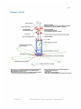
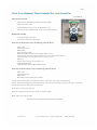
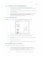
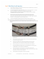
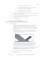
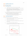
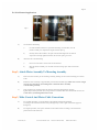
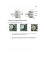
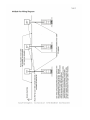
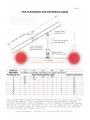
TM
Installation Manual
Page 2
Installation Manual Contents
Anatomy of a Fan --------------------------------------------------------------------------------------------------- 4
Check Your Shipment, What's Included For 6 Blade Fans --------------------------------------------------- 5
What You Need To Get Started ------------------------------------------------------------------------------------- 5
Check Your Shipment, What's Included For eco6 Guard Fan ---------------------------------------------------- 6
1 Important Information, PLEASE READ FIRST ---------------------------------------------------------------------------------- 7
1.1 Key Safety System Components -------------------------------------------------------------------------------- 7
1.2 Placement and Spacing ---------------------------------------------------------------------------------------- 7
1.3 Fan Clearance --------------------------------------------------------------------------------------------------- 7
1.4 Mark Floor To Alert Personnel ----------------------------------------------------------------------------------- 7
1.5 Sprinkler Systems and Fan Placement-------------------------------------------------------------------------- 8
1.6 Locating Control Panels ----------------------------------------------------------------------------------------- 8
1.7 Connecting Fans to Remote Controls -------------------------------------------------------------------------- 8
1.8 Shielded Motor Cable ------------------------------------------------------------------------------------------- 8
1.9 Check Federal, State and Local Codes ----------------------------------------------------------------------- 8
2.0 General Mounting Considerations ----------------------------------------------------------------------------- 8
2.1 Weight ------------------------------------------------------------------------------------------------------------ 9
2.2 Torque ------------------------------------------------------------------------------------------------------------ 9
2.3 Safety Cable ----------------------------------------------------------------------------------------------------- 9
2.4 Close Clearances ----------------------------------------------------------------------------------------------- 9
2.5 Guy Cables ------------------------------------------------------------------------------------------------------ 9
2.6 Guards ----------------------------------------------------------------------------------------------------------- 9
2.7 Universal Mounting Hardware -------------------------------------------------------------------------------- 10
2.8 Maintenance -------------------------------------------------------------------------------------------------- 10
Control Panel ---------------------------------------------------------------------------------------------------------------------------- 10
Power Unit -------------------------------------------------------------------------------------------------------------------------------- 10
Mounting Hardware ------------------------------------------------------------------------------------------------------------------ 11
Blades -------------------------------------------------------------------------------------------------------------------------------------- 11
MacroAir, Inc.
www.macroairfans.com
Toll Free: 866-668-3247
Build: March 2012
Page 3
2 Installation Procedures ----------------------------------------------------------------------------------------------------- 12
Step 1, Install Mounting Hardware ------------------------------------------------------------------------------- 12
Step 2, Attach Power Unit To Mounting Hardware --------------------------------------------------------------- 13
Step 3, Attach Safety Cable -------------------------------------------------------------------------------------- 13
Step 4, Mount The Motor Control Panel -------------------------------------------------------------------------- 13
Step 5, Mount Remote Switchbox -------------------------------------------------------------------------------- 14
Step 6, Make Control Circuit Connections ---------------------------------------------------------------------- 14
Step 7, Make Motor Lead Connections -------------------------------------------------------------------------- 15
Step 8, Install Guy Wires ------------------------------------------------------------------------------------------- 17
Step 9, Install Fan Blades, Blade Safety Links, & Safety Link Extenders ---------------------------------------- 18
Step 10, Check Clearances And Guy Wire Tension For Safety ------------------------------------------------- 19
Step 11, Install Guards If Necessary ------------------------------------------------------------------------------ 20
Step 12, Install Input Power --------------------------------------------------------------------------------------- 20
Step 13, Verify Proper Operation --------------------------------------------------------------------------------- 20
3 Installation Procedures For eco6 Guard Fan ----------------------------------------------------------------------------- 22
Step 1, Install Mounting Assembly eco6-------------------------------------------------------------------------- 22
Step 2, Attach Motor Assembly To Mounting Assembly eco6 -------------------------------------------------- 23
Step 3, Make Control And Motor Cable Connections eco6 --------------------------------------------------- 23
Step 4, Attach Rear Safety Screen eco6 ------------------------------------------------------------------------- 24
Step 5, Attach Hub And Hub Cover eco6 ------------------------------------------------------------------------ 25
Step 6, Attach Fan Blades eco6 ---------------------------------------------------------------------------------- 25
Step 7, Attach Rear Safety Screen eco6 ------------------------------------------------------------------------- 26
Step 8, Make Final Adjustments And Attach Safety Cable eco6 ---------------------------------------------- 26
Regulatory Notice ------------------------------------------------------------------------------------------------------------ 27
EMI | Electromagnetic Interference --------------------------------------------------------------------------------------------------- 27
Multi Fan Wiring Diagram ---------------------------------------------------------------------------------------------------- 28
Motor Control Panel Assembly and Wiring Illustration --------------------------------------------------------------------- 29
Fan Clearance and Extension Guide---------------------------------------------------------------------------------------- 30
Contact Information --------------------------------------------------------------------------------------------------------- 31
MacroAir, Inc.
www.macroairfans.com
Toll Free: 866-668-3247
Build: March 2012
Page 4
Anatomy of a Fan
MacroAir, Inc.
www.macroairfans.com
Toll Free: 866-668-3247
Build: March 2012
Page 5
Check Your Shipment, What's Included For 6 Blade Fans
Note: Some models may vary slightly
Blade Boxes
Blade Carton (Blades)
Power Unit Carton
Remote Control Box (where applicable)
Motor Control Panel with Variable
Frequency Drive (where applicable)
Owner's Manual with Warranty Card
Installation Manual
Gearbox Vent Cap (For Dodge Only)
Power Unit (all preassembled)
Hybrid Hub with H Beam Blade Struts
Frame
Gearbox
Motor with J-Box
Safety System
Power Unit Carton
Universal Mounting Hardware
Swivel Mount Assembly
4 Guy Wire Cables 1/8 inch
Guy Wire Clamp Pack (includes tension
tool)
Safety Cable ¼ inch
Safety Cable Bolt Pack
Blade Bolt Pack
Mounting Hardware Bolt Pack
Extended Blade Safety Links
Clamps
Shims
What You Need To Get Started
Scissor Lift
5/16 inch through ¾ inch wrench and socket set
Phillips and standard screw drivers
Torque wrench
Call MacroAir at 866.668.3247 if you have any questions
MacroAir, Inc.
www.macroairfans.com
Toll Free: 866-668-3247
Build: March 2012
Page 6
Check Your Shipment, What's Included For
eco6 Guard Fan
Eco6 Guard Fan
Motor Mount Assembly
Motor/gearbox, Hybrid Hub, and keyless bushing adapter
attached to motor mount
If ordered without safety screens, the Hybrid hub cover,
hub safety system, and blade struts will also be attached to the hub.
Wall Mount Assembly
V-shaped (roughly) wall mount
Pivot mount (attached to wall mount)
If the fan is ordered with screens, the following will be in the box.
Safety cable
Safety cable bolt kit
Blade bolt kit
Keyless bushing adapter
Bolts and washers to attach keyless bushing adapter to hub
Packet of bolts, nuts, and washers to attach rear screen to motor mount Packet of
large sheet metal screws to attach front screen to rear screen
Hub cover
Screws and star washers to attach hub cover
Solid Steel Blade Struts
Solid Steel Blade Struts to Hybrid Hub bolt pack
If the fan is ordered without screens, the following will be in the box.
Safety cable
Safety cable bolt kit
Blade bolt kit
Blade safety links and safety link extenders
Variable speed models include a control panel, remote, remote wire, motor cable and cable glands
(same as regular fan). Single speed models will have an AG Starter and AG Starter enclosure with instruc- tion manual
and warranty card loose rather than in the MCP box.
All the above is in the power unit crate.
If the fan is ordered with screens, they will be on a separate pallet.
Blades will be on a separate pallet.
Call MacroAir at 866.668.3247 if you have any questions
MacroAir, Inc.
www.macroairfans.com
Toll Free: 866-668-3247
Build: March 2012
Page 7
Please Read this Important Information Before you Install Fans
•
Make sure Power is OFF before beginning any installation or maintenance procedure.
•
Refer to the enclosed packing list and verify that all fan components are included before you begin.
1.1 Key Safety System Components
MacroAir fans are engineered with key safety features to prevent pieces of the fan from falling in the
unlikely event of a catastrophic failure. Used together, these systems and devices provide
comprehensive protection of people, equipment, and property. Follow the detailed instructions precisely
when installing fans, including the following:
Install safety cable and guy wires on every fan. Properly installed, the guy wires will keep the fan stable in case of
earthquake or in "outdoor" installations where high wind conditions may occur. The safety cable,
if installed per MacroAir specifications, will prevent the fan from falling in the unlikely event the mounting system should
fail.
Install the complete set of extended blade safety links, which connect each blade to the adjacent
blades and reinforce the area between the mounting holes. This is an important precautionary measure which will help
prevent a blade from falling should one break off at the hub for any reason.
1.2 Placement and Spacing
Check the area where fans will be mounted to determine vertical and horizontal spatial clearances. A standard ceiling
fan is mounted so the measurement from the bottom of the beam to the bottom of a
fan's hub is 3 feet. Extensions may be ordered to lower the fan if needed. Ceiling fans should be
mounted so the lowest part, the blades, are located at a minimum of 10 feet above the floor. If possible,
avoid mounting fans directly below lights or skylights to avoid any strobe effect caused by moving blades. Note, a large
fan, 20 - 24 feet in diameter, performs best at 20 to 30 feet above the floor, but acceptable performance has been
demonstrated as low as 10 feet and as high as 50 feet.
If the building has a mezzanine, fans should be mounted so a person can not reach a fan in any way from
the upper level/deck. Make certain fans are positioned so the blade tips are at least 3 feet away from any area where a
person may be able to extend outward to reach them.
1.3 Fan Clearance
Note, fans must be far enough below the ceiling to allow proper air circulation — no closer than 15% of
the fan diameter. Due to the design of our fans and mounting hardware, fan blades droop as much as a foot below the
bottom of the hub when the fan is at rest. If required, extension mounts are available from the factory. For more
information, refer to the "Fan Clearance and Extension Guide" on page 29.
1.4 Mark Floor to Alert Personnel
When mounting a fan in an area where materials may be elevated into its path, MacroAir recommends
marking or painting the floor with a large crosshatched circle to alert personnel of the overhead location of fans.
MacroAir, Inc.
www.macroairfans.com
Toll Free: 866-668-3247
Build: March 2012
Page 8
1.5 Sprinkler Systems and Fan Placement
In any installation where fire sprinklers are in place, do not interfere with their correct operation. Fans should be
located not less than 3 feet below a sprinkler, and placed central to each sprinkler quadrant.
Our standard variable-speed control system can be connected to a fire suppression control system, which
will emergency-stop fans in case of fire. Prior to installing fans, review all codes applicable to sprinkler
systems and fans to ensure code compliance. Refer to the wiring diagrams packaged inside the control panel for proper
installation. If further advice is needed, you may contact our support staff. However, it is your sole responsibility to see
that the installation is completed to code and that it is correct.
1.6 Locating Control Panels
Each fan has its own motor control panel (MCP). A motor control panel must be mounted at least 5 feet outside
maximum blade length, and within 25 feet of the fan. Make sure the lockable service disconnect
located on the side of the MCP is within line of sight of the motor to comply with OSHA and local safety codes.
1.7 Connecting Fans to Remote Controls
You may control one fan or many fans with a single remote control switch box (see illustration on page
26). The remote switch box should be located so that no more than 100 feet of cable (supplied) is
required to connect it to the motor control panel. Fans may also be controlled with temperature control
sensors and building automation systems. Contact technical support for more information on these options.
1.8 Shielded Motor Cable (For Variable Frequency Drives)
To minimize electromagnetic interference and stray voltage, each MacroAir fan assembly includes 25 feet
of shielded motor cable, cable glands, and a variable frequency drive with a built-in filter. The shielded
motor cable connects the fan motor to the motor control panel. This system reduces the likelihood of
broadcasting and receiving electronic noise which can interfere with radio and other sensitive
equipment. Plus, this system cuts fan installation cost as conduit is not needed where shielded cable is used, per the
NEC, article 336. For more regulatory information on electromagnetic interference (EMI) refer to page 25.
1.9 Check Federal, State, and Local Codes
Check all relevant codes to make sure all product certifications, product listings, and building regulations are met. Code
compliance is the responsibility of the installer.
2.0 General Mounting Considerations (I-Beam, Glulam Beam, or Other Type of Truss System)
Each type of mounting system (I-beam, glulam, or other) requires a specific mounting bracket. Most are available from
MacroAir. Before installing fans, check with the contractor, building owner, or architect to
ensure the building structure is sound and will support the weight of the fan. MacroAir, provides guidelines for
mounting fans; however, it is the sole responsibility of the building owner and
installer to ensure the safety of the mounting system, that the building structure is sound, and that the installation
complies with all federal, state, and local codes.
MacroAir, Inc.
www.macroairfans.com
Toll Free: 866-668-3247
Build: March 2012
Page 9
2.1 Weight
A standard 1-horsepower 24 foot 6-blade fan weighs about 240 pounds, including the standard mounting
hardware. In inverted-blade applications designed to blow air upward (very unusual), there is an
additional down force of about 100 pounds due to fan thrust. We recommend that a building structure
be capable of holding approximately twice the stated hanging weight of the fan. If there is some doubt of this, a
professional contractor or architect should perform a thorough evaluation of the building prior to purchasing fans.
2.2 Torque
The maximum torque (twisting force) that must be handled by the mounting system, including building structure,
occurs at fan startup. For a 24 foot fan, maximum potential starting torque is 300 ft-lbs. When
standard electrical controls are installed, the fan will never begin to approach this maximum because the
standard variable-speed control system uses soft-start technology. However, should the soft-start fail, or
when a fan is installed as a single-speed model without the variable speed control system (rare), full
torque might be applied to the mounting system, so it is important that it be adequate to withstand 300 ft- lbs torque.
2.3 Safety Cable
A MacroAir fan should never be run without a properly installed safety cable, which is supplied with every fan along with
all required hardware. You must install safety cable for warranty to be in effect.
2.4 Close Clearances
The area within three feet of the blade tips when the fan is at rest is considered "close clearance". It is
EXTREMELY DANGEROUS to mount the fans within "close clearance" of any object. We strongly
recommend not mounting the fan closer than 15% of its diameter to any object. If this is an issue,
mounting extensions and smaller fans are available from MacroAir. Refer to the illustration "Fan Clearance and
Extension Guide" on page 29.
2.5 Guy Cables
A running fan can sway due to a minor imbalance or because of wind. "Wind" may be only the air
movement the fan itself generates, or it may be actual wind if the fan is mounted outdoors or in open
areas. Since the mounting system is free swiveling, it will not stop fan movement, so it is imperative that guy wires be
properly installed. The primary considerations are angle and tension of the guy wires. See Step 10 for more
information.
2.6 Guards (except standard eco6 fan with integral guard)
If there is potential for people or objects to come in contact with a running fan, it is best to construct a
guard from angle iron and steel mesh, attaching it securely to the building structure. The guard should be mounted with
sufficient clearance so that no part of it can be pushed into the fan, with at least 18 inches of clearance on all sides. We
recommend 2" x 2" x 3/16" angle-iron for the frame, and, in most cases, 2" x
2" x 11-gage weldmesh (1/8" diameter wire on 2" centers) for the screen. However, mesh size should be
dependent on what objects might come in contact with the fan — if, for example, employees on lifts can inadvertently get
a finger into a fan, use smaller mesh or greater spacing — OSHA guidelines state that a
finger guard must prevent a finger entering into the guard within four (4) inches of the moving device, the fan blades in
this case. Refer to OSHA guidelines, paragraph 1910.212(a) (5) for more information.
MacroAir, Inc.
www.macroairfans.com
Toll Free: 866-668-3247
Build: March 2012
Page 10
2.7 Universal Mounting Hardware
We recommend mounting the fan to a horizontal structural beam, but this is not always possible in
buildings with pitched roof construction. For that reason, our universal mount is designed to swivel freely in order to allow
the fan to hang in a level position regardless of the angle of the beam it is mounted to. Our mounting hardware package
includes clamps for use with standard steel I-beams, shims for thicker steel Ibeams, and all necessary nuts and bolts. For buildings with glulam beams (laminated wood), an additional set of
brackets, available from the factory, is required (see figure 1 below).
Fig 1
Our standard mounting hardware will accommodate steel I-beams up to 5/8" thick by 10 3/4" wide. The glulam bracket
adapters will accommodate glulam beams up to 8" wide. Additional hardware for larger beams is available from the
factory.
2.8 Maintenance
Before servicing the fan or control panel ensure all POWER IS OFF and locked out to avoid injury. See Figure 2
below.
Fig 2
Control Panel
Occasional cleaning is advisable, especially when the panel is located in a dusty or dirty environment. A
can of compressed air, like that used for computer cleaning, works well to clean the inside of the panel. Simply wipe
down the outside of the enclosure with a cloth or duster periodically, if desired.
Power Unit
The gearbox is lubed for life, and we use thread locking compound on critical nuts and bolts. However, it
is a good idea to annually check that no nuts or bolts have vibrated loose. No other maintenance is required.
MacroAir, Inc.
www.macroairfans.com
Toll Free: 866-668-3247
Build: March 2012
Page 11
Mounting Hardware
Check all mounting bolts annually to be sure they have not loosened. Also, check the safety cable and
guy wires to be sure they are not loose or frayed. Loose guy wires are more likely to break than tight ones,
and broken guy wires may fall into the fan. If a guy wire is loose, carefully check to be sure it is not dam- aged, and retighten it.
Blades
Wipe any accumulated dust off all surfaces of the blades once a year. If needed, use a mild detergent solution. There is
no need to remove the blades from the fan to perform this procedure.
MacroAir, Inc.
www.macroairfans.com
Toll Free: 866-668-3247
Build: March 2012
Page 12
2 Installation Procedures
Step 1, Install mounting hardware
A)
For glulam installations, attach the glulam brackets to the beam using ½" through bolts, not supplied.
Note, ½" lag screws, also not supplied, may be used as an alternative, but will not provide as much
mounting strength. Be sure the brackets line up with each other
and that the bottom of each bracket is flush with the bottom of the beam. For glulam
installations, attach the mount directly to the bracket using the supplied ½" x 2 ¾" bolts, washers, and
nylon lock nuts. See Figure 3 below.
Fig 3
B)
For steel I-Beam installations, mount so that the large plate is against the bottom of the beam. Be
sure the plate is at a 90 degree angle to the beam and centered. Place the supplied clamps on top of
the beam and attach them to the mount using the supplied
fasteners. For thicker I-beams, use the supplied shims between the clamp and the mount as shown in
figure 4.
Fig 4
Note: In all cases, be sure to thoroughly tighten all mounting bolts and nuts. The nylon lock nuts
help prevent loosening due to vibration, but there is no substitute for proper tightening. We
recommend that nylon lock nuts not be removed and reused because this will defeat the nylon
locking; instead, buy new nylon lock nuts from your local hardware store.
C)
If an extension is to be used, attach it to the bottom of the universal mount using the
fasteners provided with the extension. Also, be sure to save the longer safety cable and guy wire
supplied with the extension; they will be needed in later steps.
D)
Loop supplied safety cable (1/4 inch steel braided cable) over the beam and let it hang.
It will be attached once the power unit is installed. If using an extension, be sure to use the longer
safety cable supplied with the extension.
MacroAir, Inc.
www.macroairfans.com
Toll Free: 866-668-3247
Build: March 2012
Page 13
Step 2, Attach Power Unit To Mounting Hardware
A)
We recommend using a scissor lift to install our fans. The best method is to place the
power unit hub-down on the lift and raise the lift until the power unit frame touches the bottom of
the universal mount or extension (if used).
B)
Once the motor frame is in contact with the mount/extension, maneuver the power unit as necessary to
line up the mounting holes.
C)
Securely attach the power unit to the mount/extension using the ½" x 1½" bolts, washers, and nylon
lock nuts included in the mounting hardware kit. Be sure to thoroughly tighten
all four bolts and nylon lock nuts to prevent vibration-related loosening. Correct tightening is
extremely important. Again, do not re-use nylon lock nuts.
Step 3, Attach Safety Cable
Refer to figure 5 as necessary. This step is required, omitting it will void manufacturer's warranty!
Fig 5
A)
Slide two of the supplied large cable clamps over each end of the safety cable.
B)
Make a loop in one end of the cable, sliding the end back through the cable clamps.
C)
Feed the other end of the safety cable through the loop, making sure that the cable goes through
the motor frame.
D)
Repeat step B for this end of the cable.
E)
Tighten the clamps securely, making sure that the u-bolts are over the free end of the cable, see
Figure 5.
Step 4, Mount The Motor Control Panel
Select a location for the MCP (Motor Control Panel) and mount securely.
A)
The MCP should be mounted so that no more than 25 feet of motor cable is required to
connect it to the fan motor. Mount it in the upright position, vertically, with the door opening to
the left. Do not mount so that the door opens downward. The mounting
surface must be non-flammable, away from sources of heat, dust, moisture, and vibration.
MacroAir, Inc.
www.macroairfans.com
Toll Free: 866-668-3247
Build: March 2012
Page 14
B)
C)
The MCP should be mounted at least 5 feet outside of the swept area of the fan blades;
this will allow safe operation of the fan and still provide access to the MCP when the fan is running.
Be sure to keep the lockable service disconnect located on the side of the MCP within line of sight
of the fan motor to comply with OSHA and local safety codes.
Mount the MCP, making sure the enclosure is firmly fixed to the mounting surface.
D)
Step 5, Mount Remote Switchbox
Select a location for the remote switchbox and mount securely.
A)
The remote switchbox should be mounted so that no more than 100 feet of remote cable is required to
connect it to the MCP.
B)
Mount the remote switchbox in a location that is easily accessible for personnel authorized
to operate the fan.
C)
Locate the switchbox in an area where it will be safe from damage caused by unintended
contact.
D)
Securely mount the remote enclosure, making sure it cannot be easily detached by incidental
contact.
Step 6, Make Control Circuit Connections
A)
Strip cable and conductors at both ends.
B)
Install one supplied strain relief fitting in the remote switchbox and make appropriate connections,
referring to the control panel schematic packaged inside the MCP, the
illustration on page 28, and/or the sticker inside the remote enclosure as needed. Close up the remote
enclosure.
C)
Install the other supplied strain relief fitting in the MCP enclosure and make control circuit
connections at the terminal strip of the VFD located inside the MCP, again referring to the
packaged control panel schematic and the illustration on page 28. Do not make any incoming
power or motor lead connections at this time.
D)
Ground the shield of the control circuit cable to the ground screw located in the lower left corner of
the VFD next to the MAINS terminal.
E)
Daisy chain additional controllers if used, referring to the packaged control panel
schematic. Ground the shielding of the cable at the slave controller side only. There is
no need to specifically designate a "Master" drive — any drive may be used as either a
master or slave with no changes. If interfacing with any kind of automated building
management system, however, please consult factory as there may be additional programming
required.
F)
Route the control circuit cables away from all incoming power and motor cables,
keeping them separated by at least 6 inches. When control circuit wiring must cross power cables,
make sure they do so at 90 degree angles to minimize interference.
MacroAir, Inc.
www.macroairfans.com
Toll Free: 866-668-3247
Build: March 2012
Page 15
Step 7, Make Motor Lead Connections
A)
Verify controller voltage; this can be found on the lower left corner of the MCP's door, as well as the
sticker on the side of the VFD (see "input").
B)
Use only the supplied motor cable for motor leads, and be sure to attach all four wires — three for
power, one for ground. The 25 foot cable is recommended to prevent voltage
and frequency fluctuations, which could cause the motor to malfunction and/or be damaged.
Consult the factory if a longer cable is required.
C)
Route motor cable away from all other power and control cables. Keep motor cable at
least 6 inches away from input power and control wiring. If the motor cable must cross
power cables or other motor control cables, make sure they do so at 90 degree angles to minimize
interference. Avoid long parallel runs to prevent signal crossover.
D)
Correctly install supplied cable glands at both ends of the motor cable (see Figure 6).
Note: For all fans, one cable gland will be attached to the motor cable. For 1 HP fans, the second
will be threaded into the motor J-box; for all other models, it will be attached to the power unit with
a cable tie.
Fig 6
i)
Take the cable gland apart and slide the gland nut over the end of the cable, threads facing
the cable end.
ii)
Slide the plastic and rubber cable gland insert over the end of the cable, with the larger
end toward the middle of the cable.
iii)
Strip the outer insulation of the cable back approximately three inches, leaving
approximately half an inch of copper foil sticking out past the outer insulation.
iv)
Slide the cable gland insert up the cable until it is flush with the outer insulation.
v)
Peel the foil shield back and fold it down over the cable gland insert. You may need to
carefully make 2 or 3 cuts in the foil so it will fold back.
vi)
Slide the threaded part of the cable gland over the end of the cable, long side
down. Work it down over the insert until only the "fingers" of the insert are visible, turning
either piece as necessary to ensure a proper fit.
vii)
Slide the gland nut up and tighten it securely onto the gland.
MacroAir, Inc.
www.macroairfans.com
Toll Free: 866-668-3247
Build: March 2012
Page 16
E)
Twist the three uninsulated stranded copper ground wires together (see figure 7) and
connect them to the green ground screw located inside of the motor junction box.
Fig 7
F)
Wire motor leads for the appropriate voltage, referring to the wiring diagram on the
motor's information label/plate or to Figure 8. Note that the top four diagrams are for U.S. motors,
while the bottom two are for CE motors, usually for use outside the U.S. Be certain to wire the motor
for the correct voltage — a mistake here can ruin the motor and/or the VFD and is not covered
under the factory warranty.
Fig 8
G)
At the other end of the cable, twist the three uninsulated stranded copper ground wires
together (see figure 7) and connect them to the ground bar located inside of the Control Panel.
Note: ALWAYS connect the ground wire of the included motor cable at both ends, MCP and motor.
H)
Connect motor leads to terminals U, V, & W on the VFD. Do not attach these leads to the
disconnect switch!
MacroAir, Inc.
www.macroairfans.com
Toll Free: 866-668-3247
Build: March 2012
Page 17
Step 8, Install Guy Wires
If an extension is installed, be sure to use the longer guy wires packaged with it. Be sure to use four guy
wires, with two clamps per end (four per guy wire). Keep the angle formed by the guy wire and the
ceiling less than 45 degrees. If longer guy wire is required, it is available inexpensively at most hardware stores. Eye
bolts (not supplied) are recommended to attach the wires to the building structure.
Note: This step is REQUIRED — omitting it may void manufacturer's warranty!
Fig 9
A)
Be sure to avoid any sharp corners to avoid fatiguing and fraying of the guy cables.
B)
Attach the guy wires to the building structure.
i)
Slide two of the supplied small cable clamps over one end of the wire.
C)
ii)
Feed that end of the wire through the eye bolt (not supplied) and back through the cable
clamps.
iii)
Tighten the cable clamps securely, keeping the u-bolt side over the free end of the cable —
see figure10 below.
Attach the guy wires to the loops on the lower section of the fan, one wire per individual
loop.
i)
Slide two of the supplied small cable clamps over the near end of the wire.
ii)
Feed that end of the wire through the guy wire loop on the fan and back through the
clamps, taking all the slack out of the cable.
iii)
Slide one clamp as close to 18 inches as possible from the fan and tighten it
securely — it needs to hold the free end of the wire in place during the tensioning
process.
iv)
Position the other clamp about two inches from the fan and tighten it just far enough to
hold it in place.
v)
Remove the rest of the slack, one guy wire at a time, using the included guy wire wrench (see
Figure 10 below). It is advisable to put a level on the hub to be sure the fan remains
horizontal.
Fig 10
MacroAir, Inc.
www.macroairfans.com
Toll Free: 866-668-3247
Build: March 2012
Page 18
1)
Attach the tool to a 3/8 inch drive ratchet.
2)
Loop the tool through the free end of the guy wire between the
clamps and turn clockwise as far as possible.
3)
Tighten the inner clamp to hold the tension.
4)
Repeat until all excess slack is out of the wire.
vi)
Loosen the outer cable clamps, pull the slack out of the free end of the wire, and position the
clamp about 18 inches from the inner one.
vii)
Re-tighten the outer clamp and double-check that the inner clamp is tight. Be sure the ubolt is over the free end of the wire to prevent slipping.
viii)
Repeat for all guy wires.
i x)
Re-check all clamps for tightness.
Step 9, Install Fan Blades and Blade Safety Links
A)
Install the fan blades.
i)
Blades should curve toward the floor (thin edge down) when correctly installed.
Whisperfoil XL blades (our standard blades) use a black extruded-aluminum
blade strut that will only allow the blade to be attached in one direction. This blade strut
has an index line in the center of one side, which should face the direction of airflow
(usually down).
Whisperfoil and Wickerbill blades use a flat steel blade strut that does not restrict
the direction the blade can be installed. Extra attention to blade direction is required
when installing these types of blades.
Fig 11
(If you are installing an inverted-blade fan (rare), the blades should curve away
from the floor. ONLY install the blades in this direction if you want the fan to blow
air up. Unless ordered from the factory as an inverted-blade fan, the blade
holders will need to be reversed for this; consult the factory before doing so.)
ii)
Slide one blade over any blade holder. For Whisperfoil XL blades, be sure the index line
of the blade holder faces down (up for inverted applications). For Whisperfoil or
Wickerbill blades, be sure the blade curves downward.
iii)
Line up the bolt holes in the blade with the holes in the blade holder.
iv)
Repeat for each blade.
MacroAir, Inc.
www.macroairfans.com
Toll Free: 866-668-3247
Build: March 2012
Page 19
B)
Install extended blade safety links . This step is REQUIRED — omitting it will void
manufacturer's warranty!
Fig 12
C)
i)
On top of one blade, place a safety link, so the long leg lines up with the holes in the blade.
Put a bolt through the outer blade hole just to hold the link in place — don't put a nut on it at
this point, though.
ii)
On top of the next blade, place a second safety link so that the short end is on top of the
previous safety link. (See Figure 2 above).
iii)
Line up the inner hole of the blade with the holes in both safety links. Put a bolt through
each of the holes on this blade.
iv)
Securely tighten an included nylon lock nut onto each of the bolts, using an
included flat washer between the nut and the blade. The safety link will bend
when the nut closest to the hub is tightened due to the angle of the blade struts.
v)
Repeat for the rest of the blades.
vi)
Once the starting point is reached, slide the final safety link between the short
end of the first safety link and the blade. Follow steps iii and iv to attach like the rest.
Check that all bolts are tightened firmly —- blade bolts require 23 ft-lbs of torque. Blades
should not rattle when the fan is running.
Step 10, Check Clearances And Guy Wire Tension For Safety
A)
Rotate the fan slowly one time by hand to find the position and blade with the least
clearance from any possible obstructions. If necessary, reposition the fan to prevent any dangerous
conditions.
Note: At rest, the blade tips droop lower than they will be in operation due to gravity. For our
largest fans, this deflection can be approximately one foot.
B)
Double check guy wire tension by attempting to move the fan in any horizontal direction
and by trying to pull down on the guy wires. They should be very difficult to move. If
there is visible slack in any guy wire or if any moves easily, re-tension them before proceeding.
MacroAir, Inc.
www.macroairfans.com
Toll Free: 866-668-3247
Build: March 2012
Page 20
Step 11, Install Guards If Necessary
Refer to Section 2.6 on page 10 for guidelines.
Step 12, Install Input Power
A)
Verify that input power voltage and number of phases match that of the MCP.
B)
Determine the appropriate size for the input circuit by multiplying the maximum input amperage of
the VFD — found on the door of the MCP and on the included control
panel schematic (wiring diagram) — by the number of fans to be placed on the circuit. Be sure the
breakers used match the voltage of the VFD. Each MCP contains input fuses
providing individual circuit protection for each unit, but an appropriately-sized input breaker must
still be installed.
C)
Connect a ground wire from the supply panel to the ground bar located inside of MCP.
Note: ALWAYS connect the grounding bar in the MCP to ground at the power panel — when
pulling power from the main panel, be sure to pull a full sized ground.
D)
Connect input power leads to the proper terminals of the disconnect switch located on
the side of the MCP. Do not connect these wires directly to the VFD!
Step 13, Verify Proper Operation
Leave the door of the MCP open during this process so the front of the VFD is visible.
A)
Turn the service disconnect to the On position. When power is applied, the green On indicator
(located on the front of the VFD) will light.
B)
Adjust the speed control knob (located on the remote switchbox) to 4.
C)
Turn the For-Off-Rev (Forward/ Off/ Reverse) switch (located on the remote switchbox) to the For
(Forward) position.
D)
After a 15 second delay, the fan will begin to accelerate slowly.
E)
Verify proper rotation with the For-Off-Rev switch in the For position: the rotor should be turning in
the counter-clockwise direction when viewed from the floor — see figure 13.
Fig 13
P ro p
as vieer directio
wed
f r o m n o f b la d e
o u te r
end rootation
f b la d e
MacroAir, Inc.
www.macroairfans.com
Toll Free: 866-668-3247
Build: March 2012
Page 21
F)
If the fan is turning the wrong way on initial startup, follow the procedure below:
i)
Verify that the For-Off-Rev switch is in the For position.
ii)
If so, turn the switch to the Off position.
iii)
Carefully remove the remote switch box faceplate with the switches attached
and turn it over. Verify that the wiring to the For-Off-Rev switch matches the wiring
diagram (there should be a sticker inside the remote enclosure). If it's
wrong, correct it and re-test the fan. Reattach the faceplate (before testing).
iv)
If step iii does not solve the problem, turn off the disconnect switch on the MCP and snap
the small cover off the VFD. Ensure that the wiring matches the wiring diagram — this can
be found on the included control panel drawing as well as
on a sticker inside the control panel door. If this wiring is wrong, correct it, replace the
cover, and test the fan again.
v)
If step iv does not solve the problem, simply switch any two of the three power
wires from the MCP to the fan motor, either at the MCP or at the motor. Turn the power
back on and re-test the fan.
vi)
If none of these steps fix the problem (extremely unlikely,) contact the factory for further
assistance.
vii)
Be sure the remote box is re-assembled and the cover is back on the VFD before proceeding.
G)
Adjust the speed control to 9 and verify full speed operation with no Fault or Warning
indicators lit on the VFD. Contact factory if fault/warning condition occurs.
H)
Close up the MCP.
I)
Adjust fan speed and direction for desired operation.
MacroAir, Inc.
www.macroairfans.com
Toll Free: 866-668-3247
Build: March 2012
Page 22
3 Installation Procedures For
eco6 Guard Fan
Step 1, Install Mounting Assembly
For Wall-Mounted Applications
Fig 14
A)
Mark a level line on the wall at the desired mounting height to locate the top edge of the upper mount
plate.
B)
Use the mount as a template to carefully mark the locations of the mounting holes on the
wall. There should be six holes total: four in the upper plate and two in the lower plate. Be sure to
align the top edge of the upper mount plate with your level line.
C)
Remove the mount from the wall and pre-drill mounting holes for the appropriate mounting
fasteners.
D)
Attach the pre-assembled mount/pivot unit to the wall.
For concrete or masonry walls:
i)
Insert Red Head or equivalent 1/2" self-anchoring studs (not included) into the
mounting holes, properly securing them according to manufacturer's instructions.
ii)
Slide the mount plates over the studs and attach using nylon lock nuts and flat washers,
being careful not to over-tighten.
Note:
We recommend that nylon lock nuts not be removed and reused because this will defeat
the nylon locking; instead, buy new nylon lock nuts from your local hardware store.
For wood surfaces (wood studs): Before mounting the fan to a wood surface, ensure that
the structure will safely support the fan's weight (see spec. sheet).
i)
Line the mount assembly up with the mounting holes.
ii)
Insert 1/2" lag bolts (not included) into the holes, using washers to maximize the
hold. Be sure that you use bolts long enough to support the weight of the fan. Tighten the
bolts securely, but do not over-tighten them.
MacroAir, Inc.
www.macroairfans.com
Toll Free: 866-668-3247
Build: March 2012
Page 23
For Pole-Mounted Applications
Fig 15
A)
B)
Cut and mount bracketing.
i)
Cut and assemble UniStrut or equivalent bracketing (not included). Use the
mount assembly as a template for length and hole spacing.
ii)
Securely attach the brackets to the pole at the desired height. Be sure that all
strap bolts are firmly tightened and that the vertical spacing is correct.
Attach the fan to the bracketing.
i)
Insert 1/2" bolts with 1 washer each into the brackets.
ii)
Slide the mount assembly over the bolts and attach using nylon lock nuts and flat
washers.
Step 2, Attach Motor Assembly To Mounting Assembly
A)
Place the motor assembly on the mounting assembly, making sure the mount assembly pivot section
is flat.
B)
Rotate the motor assembly to approximately the desired horizontal angle. Make sure to leave enough
room to use at least three (3) mounting bolts to attach the motor assembly
to the mounting assembly.
C)
Insert supplied 1/2" mounting bolts and washers downward through holes. Securely
tighten the provided nylon lock nuts, using washers to maximize hold. Four mount bolts are best, but
at least three (3) mounting bolts must be used.
Step 3, Make Control And Motor Cable Connections
A)
For variable-speed fans, set up the Motor Control Panel and Remote Switchbox
according to the instructions found in Step 4 through Step 7 of the regular instructions (pages 12
through 15).
B)
For single-speed fans, wire up the included circuit breaker/starter according to the instructions
printed on the inside of the box.
MacroAir, Inc.
www.macroairfans.com
Toll Free: 866-668-3247
Build: March 2012
!
!
!
!
!
!
!