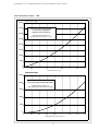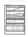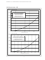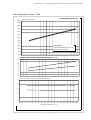
1
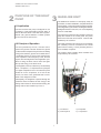
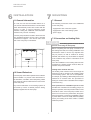
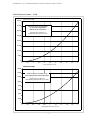
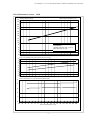
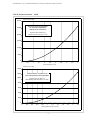
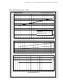
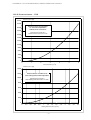
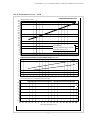
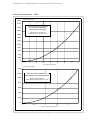
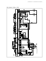
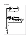
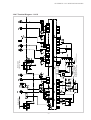
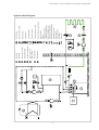
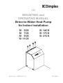
CE
MOUNTING and
OPERATING MANUAL
Brine-to-Water Heat Pump
for Indoor Installation
SI
SI
SI
SI
5CS
7CS
9CS
11CS
SI 14CS
SI 17CS
SI 21CS
Order No.: 452230.67.01
FD 8404
1
CONTENTS
1
READ IMMEDIATELY
1.1
1.2
Important Information
Legal Provisions and Directives
1.3
Energy-Efficient Use of the Heat Pump
2
PURPOSE OF THE HEAT
PUMP
3
4
2.1
Application
2.2
Principle of Operation
3
BASELINE UNIT
4
4
ACCESSORIES
5
4.1
Brine Manifold
5
TRANSPORT
5
6
INSTALLATION
6
6.1
General Information
6.2
Sound Emissions
7
MOUNTING
7.1
7.2
7.3
General
Connection on Heating Side
Connection on Heat Source Side
7.4
Electrical Connection
8
COMMISSIONING
8.1
8.2
General
Preparation
8.3
Commissioning Procedure
9
CARE/CLEANING
9.1
9.2
Care
Cleaning of Heating Side
9.3
Cleaning of Heat Source Side
6/7
8
9
10 MALFUNCTIONS/TROUBLESHOOTING
10
11 DECOMMISSIONING
10
11.1 Shutdown in Summer
11.2 End-of-Life Decommissioning
12 Appendix
11
2
READ IMMEDIATELY
1
READ IMMEDIATELY
CAUTION!
Any work on the heat pump may only
be performed by authorised and qualified
customer service technicians.
1.1 Important Information
CAUTION!
The heat pump is not attached to the
wooden pallet.
CAUTION!
All power circuits must be disconnected from the power source prior to
opening the cabinet.
CAUTION!
The heat pump must not be tilted
more than max. 45° (in either direction).
1.2 Legal Provisions and Directives
This heat pump conforms to all relevant DIN/VDE
regulations and EU directives. For details refer to
the EC Declaration of Conformity in the appendix.
CAUTION!
The electrical connection of the heat pump must be
performed according to and conforming with all relevant VDE, EN and IEC standards. Beyond that, the
connection requirements of the local utility companies have to be observed.
Do not lift unit by the holes in the
panel assemblies!
CAUTION!
The heat pump is to be connected to the heat source
and heat distribution systems in accordance with all
applicable provisions.
Flush the heating system prior to
connecting the heat pump.
CAUTION!
The supplied strainer is to be fitted
in the heat source inlet of the heat pump in order
to protect the evaporator against contamination.
1.3 Energy-Efficient Use of the Heat
Pump
By operating this heat pump you contribute to the
protection of our environment. A prerequisite for an
efficient operation is the proper design and sizing of
the heating system and the heat source system. In
particular, it is important to keep water flow
temperatures as low as possible. All energy
consumers connected should therefore be suitable
for low flow temperatures. A 1 K higher heating water
temperature corresponds to an increase in power
consumption of approx. 2.5 %. Underfloor heating
systems with flow temperatures between 30 °C and
40 °C are optimally suited for energy-efficient
operation.
CAUTION!
The brine must contain at least 25 %
of a frost and corrosion protection agent on a
monoethylene glycol or propylene glycol basis.
CAUTION!
The clockwise phase sequence
must be observed when connecting the load
line.
CAUTION!
CAUTION!
Commissioning of the heat pump
must be performed in accordance with the
mounting and operating manual of the heat
pump controller.
3
PURPOSE OF HEAT PUMP
BASELINE UNIT
2
PURPOSE OF THE HEAT
PUMP
3
2.1 Application
The brine-to-water heat pump is designed for use
in existing or newly built heating systems. Brine is
used as the heat carrier in the heat source system.
Ground coils, ground collectors or similar systems
can be used as the heat source.
BASELINE UNIT
The baseline unit consists of a heat pump, ready for
connection, for indoor installation, complete with sheet
metal cabinet, control panel and integrated controller.
The refrigeration cycle contains the refrigerant R407C.
Refrigerant R407C is CFC-free, non-ozone depleting
and non-combustible.
All components required for the operation of the heat
pump are located on the control panel. The power
feed for the load and control current must be fieldinstalled by the customer.
The supply lead of the brine pump (to be provided by
the customer) must be connected to the control
panel. When so doing, a motor protecting device is
to be installed, if required.
2.2 Principle of Operation
The heat generated by the sun, wind and rain is
stored in the ground. This heat stored in the ground
is collected at low temperature by the brine circulating
in the ground collector, ground coil or similar device.
A circulating pump then conveys the warmed brine
to the evaporator of the heat pump. There, the heat
is given off to the refrigerant in the refrigeration cycle.
When so doing, the brine cools so that it can again
take up heat energy in the brine circuit.
The collector loops including brine manifold must
be provided by the customer.
1
2
3
The refrigerant, however, is drawn in by the electrically
driven compressor, is compressed and "pumped"
to a higher temperature level. The electrical power
needed to run the compressor is not lost in this
process, but most of the generated heat is transferred to the refrigerant as well.
Subsequently, the refrigerant is passed through the
condenser where it transfers its heat energy to the
heating water. Based on the thermostat setting, the
heating water is thus heated to up to 55 °C.
4
1) Condenser
2) Control panel
4
3) Evaporator
4) Compressor
ACCESSORIES
TRANSPORT
4
ACCESSORIES
4.1 Brine Manifold
5
The brine manifold ties the individual collector loops
of the heat source system into a single main line
which is connected to the heat pump. Integrated ball
valves allow individual brine circuits to be shut off for
venting purposes.
TRANSPORT
A lift truck is suited for transporting the unit on a level
surface. If the heat pump needs to be transported
on an uneven surface or carried up or down stairs,
carrying straps may be used for this type of transport.
These straps may be passed directly underneath
the wooden pallet.
CAUTION!
The heat pump is not secured to the
wooden pallet.
CAUTION!
The heat pump must not be tilted
more than max. 45° (in either direction).
For lifting the unit without pallet, the holes provided
in the sides of the frame should be used. The side
panel assemblies must be removed for this
purpose. A commercially available pipe can be used
as a carrying aid.
CAUTION!
Do not use the holes in the panel
assemblies for lifting the unit!
5
INSTALLATION
MOUNTING
6
INSTALLATION
7
6.1 General Information
As a rule, the unit must be installed indoors on a
level, smooth and horizontal surface. The entire base
frame should thereby make close contact with the
surface in order to ensure adequate sound
insulation. Failing this, additional sound insulation
measures may become necessary.
The heat pump should be located to allow safe and
easy maintenance/service access. This is ensured
if a clearance of approx. 1 m in front of and to each
side of the heat pump is maintained.
MOUNTING
7.1 General
The following connections need to be established
on the heat pump:
- supply/return flow of the brine system
- supply/return flow of the heating system
- power supply
7.2 Connection on Heating Side
CAUTION!
The heating system must be flushed
prior to connecting the heat pump.
1m
Before completing the heat pump connections on
the heating water side, the heating installation must
be flushed in order to remove any impurities that
may be present, as well as residues of sealing
material, and the like. Any accumulation of deposits
in the condenser may result in a total failure of the
heat pump.
1m
Once the installation on the heating side has been
completed, the heating system must be filled, deaerated and pressure-tested.
1m
Heating water minimum flow rate
The heating water minimum flow rate through the
heat pump must be assured in all operating states
of the heating system. This can be accomplished,
for example, by installing a differential pressure-free
manifold or an overflow valve. The procedure for
setting an overflow valve is described in the Chapter
Commissioning.
6.2 Sound Emissions
The heat pump offers silent operation due to efficient
sound insulation. To prevent noise transmission to
the foundation, a suitable, sound dampening rubber
mat should be placed underneath the base frame
of the heat pump.
Any sound transmission to the heating systems is
prevented by means of flexible pressure tubing
already integrated into the heat pump.
Frost protection for installations prone to frost
Provided the controllers and circulating pumps are
ready for operation, the frost protection feature of the
controller is active. If the heat pump is taken out of
service or in the event of a power failure, the system
has to be drained. In heat pump installations where
a power failure cannot be readily detected (holiday
house), the heating circuit must contain a suitable
antifreeze product.
6
MOUNTING
7.3 Connection on Heat Source Side
An all-pole disconnecting device with a contact gap
of at least 3 mm (e.g. utility company disable contactor or power contactor) as well as a 3-pole circuit
breaker with simultaneous tripping of all external
conductors must be provided . The required crosssectional area of the conductor is to be selected
according to the power consumption of the heat
pump, the technical connection requirements of the
relevant utility company and all applicable regulations. Power consumption data of the heat pump is
provided in the product literature and on the
nameplate. The terminals are designed for a max.
conductor cross-section of 10 mm˝.
The following procedure must be observed when
making the connection:
Connect the brine line to the flow and return pipe
of the heat pump.
CAUTION!
The supplied strainer must be fitted
in the heat source inlet of the heat pump in order
to protect the evaporator against the ingress
of impurities.
In addition, a powerful vent must be installed at
the highest point of the heat source system. The
hydraulic plumbing diagram must be observed
here.
CAUTION!
The clockwise phase sequence
must be observed when connecting the load line
(the heat pump will deliver no output and will be
very noisy when the phase sequence is incorrect).
The brine liquid must be produced prior to
charging the system. The brine concentration
must be at least 25 %. Freeze protection down to
-14°C can thus be ensured.
Only antifreeze products on the basis of monoethylene glycol or propylene glycol may be used.
The heat source system must be vented (deaerated) and be checked for leaks.
CAUTION!
The brine solution must contain at
least 25 % of an antifreeze and corrosion
protection agent on a monoethylene glycol or
propylene glycol basis.
7.4 Electrical Connection
The following electrical connections must be
established on the heat pump:
-
Connection of the control wire to the control panel
of the heat pump via terminals X1: L/N/PE.
-
Connection of the load wire to the control panel
of the heat pump via terminals X5: L1/L2/L3/PE.
-
Connection of the brine pump (to be provided by
the customer) to the control panel of the heat
pump via terminal X1: PE and pump contactor
K2: 2/4/6 (.. 5-17CS), or motor protection F7: 2/4/
6 (.. 21CS).
All electrical components required for the operation
of the heat pump are located on the control panel.
For detailed instructions concerning the connection
and functioning of the heat pump controller refer to
the operating manual supplied with the controller.
7
COMMISSIONING
8
b) Close all of the heating circuits that may also be
closed during operation (depending on the type
of heat pump usage) so that the most unfavourable operating state - with respect to the water
flow rate - is achieved.
COMMISSIONING
8.1 General Information
To ensure proper commissioning it should be
carried out by an after-sales service authorized by
the manufacturer. Only then can an extended
warranty period of 3 years in total be granted (cf.
Warranty service).
c) In this operating state open the overflow valve
until approximately the same temperature
difference exists that was measured under a)
when the overflow valve was closed and the
heating circuits open.
Any malfunctions occurring during operation are
displayed on the heat pump controller and can be
corrected as described in the operating manual of
the heat pump controller.
8.2 Preparation
Prior to commissioning, the following items need to
be checked:
- All connections of the heat pump must have been
made as described in Chapter 7.
- The heat source system and the heating circuit
must have been filled and checked.
- The strainer must have been fitted in the sole
inlet of the heat pump.
- In the brine and heating circuits all valves that
could impair the proper heating water flow must
be open.
- The settings of the heat pump controller must be
adapted to the heating installation in accordance
with the instructions contained in the controller's
operating manual.
8.3 Commissioning Procedure
The start-up of the heat pump is effected via the heat
pump controller.
CAUTION!
Commissioning of the heat pump
must be performed in accordance with the
mounting and operating manual of the heat
pump controller.
Where an overflow valve is fitted to assure the
minimum heating water flow rate, the valve must be
set in accordance with the requirements of the
heating installation. An incorrect setting may result
in various error symptoms and an increased electric power consumption. To correctly set the overflow
valve, the following procedure is recommended:
a) Open all heating circuits and close the overflow
valve. Determine the resulting temperature
difference between supply and return flow.
8
CARE/CLEANING
9
CARE/CLEANING
CAUTION!
Caution - Heating Technicians !
Depending on the filling water quality and
quantity, in particular in the case of mixed
installations and plastic pipes, mineral deposits
(rust sludge, lime) may form, impairing the proper functioning of the heating installation. A
reason for this is the water hardness and
oxygen dissolved in the filling waters as well
as additional oxygen from the air, which may
penetrate via valves, fittings and plastic pipes
(oxygen diffusion). As a preventive measure it
is recommended that a physical water conditioner such as ELYSATOR be used.
9.1 Care
The heat pump is maintenance-free. To prevent
malfunctions due to sediments in the heat exchangers, care must be taken that no impurities can
enter the heat source system and heating installation. In the event that operating malfunctions due to
contamination occur nevertheless, the system
should be cleaned as described below.
9.2 Cleaning of Heating Side
The ingress of oxygen into the heating water circuit
may result in the formation of oxidation products
(rust). It is therefore important - in particular with
respect to the piping of underfloor heating systems
- that the installation is executed in a diffusion-proof
manner.
9.3 Cleaning of Heat Source Side
CAUTION!
The supplied strainer is to be installed in the heat source inlet of the heat pump in
order to protect the evaporator against contamination.
Also residues of lubricating and sealing agents may
contaminate the heating water.
In the case of severe contaminations leading to a
reduction of the performance of the condenser in
the heat pump, the system must be cleaned by a
heating technician.
The filter screen of the strainer should be cleaned
one day after commissioning, thereafter every week.
If no more contamination can be noticed any more,
the strainer filter can be removed in order to reduce
pressure losses.
According to current knowledge, we recommend
cleaning with a 5% phosphoric acid solution or, in
the case that cleaning needs to be performed more
frequently, with a 5% formic acid solution.
In either case, the cleaning fluid should be at room
temperature. It is recommended that the heat
exchanger be cleaned in the direction opposite to
the normal flow direction.
To prevent acidic cleaning agents from entering the
circuit of the heating installation we recommend that
the flushing device be fitted directly to the supply
and return lines of the condenser. To prevent any
damage caused by cleaning agent residues that
may be present in the system it is important that the
system be thoroughly flushed using appropriate
neutralising agents.
The acids must be used with great care, all relevant
regulations of the employers' liability insurance
associations must be adhered to.
If in doubt, contact the manufacturer of the chemicals!
9
MALFUNCTIONS/TROUBLESHOOTING
DECOMMISSIONING
10
MALFUNCTIONS/
TROUBLESHOOTING
11
DECOMMISSIONING
11.1 Shutdown in Summer
Shutting down the heating system in summer is
effected by switching the heat pump controller to the
"Summer" operating mode.
This heat pump is a quality product and is designed
for trouble-free operation. In the event that a
malfunction occurs nevertheless, you will be able to
correct the problem yourself in most of the cases.
Simply consult the Malfunctions and Troubleshooting table contained in the operating manual of
the heat pump controller.
11.2 End-of-Life Decommissioning/
Disposal
Additional malfunctions can be interrogated at the
heat pump controller.
Before removing the heat pump, disconnect the
machine from the power source and close all valves.
Environment-relevant requirements regarding the
recovery, recycling and disposal of service fuels and
components in accordance with all relevant standards
must be adhered to. Particular attention must hereby
be paid to the proper disposal of refrigerants and
refrigeration oils.
If you cannot correct the malfunction yourself, please
contact the after-sales service agent in charge (see
Warranty Certificate).
CAUTION!
All work on the heat pump may only
be performed by an authorised and qualified
after-sales service.
CAUTION!
All electrical circuits must be disconnected from the power source prior to
opening the equipment.
10
APPENDIX
12
APPENDIX
12.1
12.1.1
12.1.2
Dimensioned Drawings
Dimens'ddrawing .. 5CS - 14CS 12
Dimens'd drawing .. 17CS - 21CS 13
12.2
Equipment Data
14
12.3
Performance Curves/Pressure
Losses
Performance Curves .. 5CS
Pressure Losses .. 5CS
Performance Curves .. 7CS
Pressure Losses .. 7CS
Performance Curves .. 9CS
Pressure Losses .. 9CS
Performance Curves .. 11CS
Pressure Losses .. 11CS
Performance Curves .. 14CS
Pressure Losses .. 14CS
Performance Curves .. 17CS
Pressure Losses .. 17CS
Performance Curves .. 21CS
Pressure Losses .. 21CS
15
16
17
18
19
20
21
22
23
24
25
26
27
28
12.3.1
12.3.2
12.3.3
12.3.4
12.3.5
12.3.6
12.3.7
12.3.8
12.3.9
12.3.10
12.3.11
12.3.12
12.3.13
12.3.14
12.4
12.4.1
12.4.2
12.4.3
11
12.4.4
12.4.5
12.4.6
12.4.7
12.4.8
Wiring Diagram
Control .. 5CS to .. 17CS
Load .. 5CS bis .. 17CS
Terminal Diagram
.. 5CS to .. 17CS
Legend .. 5CS to .. 17CS
Control .. 21CS
Load .. 21CS
Terminal Diagram .. 21CS
Legend .. 21CS
31
32
33
34
35
36
12.5
Hydraulic Block Diagram
37
12.6
EC Declaration of Conformity
38
12.7
Warranty Certificate
39
29
30
Heating water supply
Heat pump outlet
Heating water return
Heat pump inlet
Heat source return
Heat pump inlet
Heat source supply
Heat pump outlet
1 1/4" internal / 1 1/4" external thread
Connections on heat source side
Connections on heating side
1" internal / 1" external thread
APPENDIX: 12.1 DIMENSIONED DRAWINGS
12.1.1 Dimensioned Drawing .. 5CS - 14CS
12
Heating water supply
Heat pump outlet
Heating water return
Heat pump inlet
Heat source return
Heat pump inlet
Heat source supply
Heat pump outlet
1 1/2" internal / 1 1/2" external thread
Connections on heat source side
Connections on heating side
1 1/4" internal / 1" external thread
APPENDIX: 12.1 DIMENSIONED DRAWINGS
12.1.2 Dimensioned Drawings .. 17CS - 21 CS
13
14
ELECTRICAL CONNECTION
5
ja
Subject to technical modifications
Issued 24.03.2004
See EC Declaration of Conformity
3)
internal
Controller internal / external
internal
yes
1
These data characterize the size and performance capability of the system. For economic and energetic reasons, additional factors such as balance
point and control need to be taken into consideration. Abbreviations have the following meaning, e.g. B10 / W55: heat source temperature 10 °C and
heating water supply temperature 55 °C.
1
3)
2,89
30 (w/out soft st.)
1,6
400 / 16
133
thread 1¼" i/ext.
thread 1" i/ext.
800 × 600 × 500
R407C / 1,5
1,7 / 10000
0,6 / 2500
55
6,9 / 4,3
6,7 / 2,9
5,6 / 2,2
9,9
7.3
Performance settings
7.2
3)
2,22
22 (w/out soft st.)
1,23
400 / 16
131
thread 1¼" i/ext.
thread 1" i/ext.
800 × 600 × 500
R407C / 1,7
1,2 / 6500
0,45 / 2000
54
5,3 / 4,3
4,8 / 2,75
3,8 / 1,96
10,1
0,25
monoethylene glycol
monoethylene glycol
0,25
-5 to +25
max. 55
indoors
IP 20
..7CS
-5 to +25
max. 55
indoors
IP 20
..5CS
1)
OTHER DESIGN CHARACTERISTICS
Water inside equipment protected against freezing 2)
COMPLIES WITH EUROPEAN SAFETY REGULATIONS
6
7
A / ---
Nominal current B0 W35 / cosϕ
5.4
7.1
A
Starting current with soft starter
5.3
kW
Nominal voltage; fusing
Nominal power consumption 1)
5.1
V/A
kg
inches
inches
H x W x L mm
Type / kg
m³/h / Pa
m³/h / Pa
dB(A)
5.2
B0 W35
Equipment connections for heat source
Weight of transport unit(s) incl. packaging
4.3
Equipment connections for heating system
4.2
4.4
DIMENSIONS; CONNECTIONS AND WEIGHT
Equipment dimensions without connections 4)
4
Brine flow rate at internal pressure difference (heat source)
Refrigerant; total charge weight
3.6
3.7
4.1
Sound power level
Heating water flow rate at internal pressure difference
3.4
kW / --kW / ---
at B0 / W50 1)
at B0 / W35 1)
3.5
kW / ---
at B-5 / W55 1)
Heating capacity / coeff.of perform.
3.3
Minimum brine concentration (-13°C freezing temperature)
Heating water temperature spread at B0 / W35
3.2
K
°C
Antifreeze agent
°C
Brine (heat source)
Operating temperature limits:
Heating water supply
PERFORMANCE DATA
3
Enclosure type acc. to EN 60 529
Installation site
2.1
2.2
3.1
TYPE AND COMMERCIAL DESCRIPTION
MODEL
1
2
EQUIPMENT DATA for brine-to-water heat pumps for heating purposes
internal
1
yes
3)
3,77
15
2,07
4)
2)
400 / 16
134
thread 1¼" i/ext.
thread 1" i/ext.
800 × 600 × 500
R407C / 1,8
2,3 / 16000
0,75 / 4500
56
9,2 / 4,4
9,0 / 3,1
7,7 / 2,3
10,5
0,25
monoethylene glycol
-5 to +25
max. 55
indoors
IP 20
..9CS
internal
1
yes
3)
5,81
26
3,22
400 / 16
157
thread 1¼" i/ext.
thread 1" i/ext.
800 × 600 × 500
R407C / 2,3
3,5 / 13000
1,3 / 3500
56
14,5 / 4,5
14,2 / 3,4
12,5 / 2,6
9,6
0,25
monoethylene glycol
-5 to +25
max. 55
indoors
IP 20
..14CS
internal
1
yes
3)
6,35
27
3,72
400 / 16
165
thread 1½" i/ext.
1380 × 600 × 500
R407C / 2,8
3,8 / 9000
1,5 / 4000
58
17,1 / 4,6
16,7 / 3,2
14,4 / 2,6
9,3
0,25
-5 to +25
max. 55
indoors
IP 20
..17CS
internal
1
yes
3)
8,86
29
4,91
400 / 20
215
1380 × 600 × 500
R407C / 4,5
6,0 / 12000
1,6 / 6000
59
21,1 / 4,3
20,4 / 3,1
17,9 / 2,5
11,3
0,25
-5 to +25
max. 55
indoors
IP 20
..21CS
Please keep in mind that morer space is required for pipe connection, operation and maintenance.
The heating circulating pump and the controller of the heat pump must be ready for operation at all times.
internal
1
yes
3)
4,84
26
2,66
400 / 16
145
thread 1¼" i/ext.
thread 1" i/ext.
800 × 600 × 500
R407C / 2,0
3,0 / 13000
1,0 / 3500
56
11,8 / 4,4
11,3 / 3,0
9,4 / 2,4
10,1
0,25
monoethylene glycol
-5 to +25
max. 55
indoors
IP 20
..11CS
APPENDIX: 12.2 EQUIPMENT DATA
Equipment Data
APPENDIX: 12.3 PERFORMANCE CURVES/PRESSURE LOSSES
12.3.1 Performance Curves .. 5CS
Water outlet temperature in
in [°C]
[°C]
Wasseraustrittstemperatur
Heating
capacity
in [kW]
Heizleistung
in [kW]
16
14
12
10
35
50
8
6
Bedingungen:
Conditions:
3
Heating water flow rate 0,45
/h
Heizwasserdurchsatz
0,45mm³/h
3
/h
Brine flow rate 1,2
Soledurchsatz
1,2mm³/h
4
2
0
Leistungszahl
im Heizbetrieb
Der anteiligen
Pumpenleistungen)
COP
in the heating
mode (incl.(incl.
proportional
pump energy)
8
35
7
6
50
5
4
3
2
1
0
Leistungsaufnahme
in [kW]
(incl. Derpump
anteiligen
Power
consumption (incl.
proportional
powerPumpenleistungen)
input)
4
3
2
50
35
1
0
-10 -8
-6
-4
-2
0
2
4
6
8
10
12
14
Brine inlet temperature in
Soleeintrittstemperatur
in[°C]
[°C]
15
16
18
20
22
24
26
APPENDIX: 12.3 PERFORMANCE CURVES/PRESSURE LOSSES
12.3.2 Pressure Losses .. 5CS
Pressure
loss inin[Pa]
Druckverlust
[Pa]
40000
Druckverluste
Pressure
losses Verdampfer
of evaporator
Soletemperature
-5°C
at –5°Cbei
brine
without
accessories
ohnebrine
Solezubehör
35000
30000
Pressure
loss 6,5
6.5 kPa
kPa bei
at a
Druckverlust
rated
brine flow rate of1,2
1.2m³/h
m3/h
Sole-Nenndurchfluß
25000
20000
15000
10000
5000
0
0
0,5
1
1,5
2
2,5
3
Brine flow rate in
/h]
Soledurchfluß
in [m
[m³/h]
3
3,5
4
1,2
1,4
1,6
Pressure
loss inin[Pa]
Druckverlust
[Pa]
25000
Druckverluste
Pressure
losses ofVerflüssiger
condenser at
35°C heatingbei
water
outlet
HWA
35°Ctemperature
20000
Pressure
loss 2
Druckverlust
2 kPa
kPa at
beia
rated
heating water flow rate of0,45
0.45m³/h
m3/h
Heizwasser-Nenndurchfluß
15000
10000
5000
0
0
0,2
0,4
0,6
0,8
1
3
Heizwasserdurchfluß
[m³/h]
Heating water flow rate in
in [m
/h]
16
APPENDIX: 12.3 PERFORMANCE CURVES/PRESSURE LOSSES
12.3.3 Performance Curves .. 7CS
Wasseraustrittstemperatur
[°C]
Water outlet temperature in
in [°C]
Heating
capacity
in [kW]
Heizleistung
in [kW]
16
14
12
35
50
10
8
6
Bedingungen:
Conditions:
3
Heating water flow rate 0,6
0,6 m
/h
Heizwasserdurchsatz
m³/h
3
Brine flow rate 1,7
/h
Soledurchsatz
1,7mm³/h
4
2
0
Leistungszahl
im Heizbetrieb
Der anteiligen
Pumpenleistungen)
COP in the heating
mode (incl.(incl.
proportional
pump energy)
8
35
7
6
50
5
4
3
2
1
0
Power
consumption (incl.
proportional
power
input)
Leistungsaufnahme
in [kW]
(incl. Derpump
anteiligen
Pumpenleistungen)
4
3
50
2
35
1
0
-10 -8
-6
-4
-2
0
2
4
6
8
10
12
14
Soleeintrittstemperatur
in[°C]
[°C]
Brine inlet temperature in
17
16
18
20
22
24
26
APPENDIX: 12.3 PERFORMANCE CURVES/PRESSURE LOSSES
12.3.4 Pressure Losses .. 7CS
Pressure
loss inin[Pa]
Druckverlust
[Pa]
40000
Druckverluste
Pressure
losses Verdampfer
of evaporator
Soletemperature
-5°C
at –5°Cbei
brine
without
accessories
ohnebrine
Solezubehör
35000
30000
Pressure
loss 10
10 kPa
kPa bei
at a
Druckverlust
rated
brine flow rate of1,7
1.7m³/h
m3/h
Sole-Nenndurchfluß
25000
20000
15000
10000
5000
0
0
0,5
1
1,5
2
2,5
3
Brine flow rate in
/h]
Soledurchfluß
in [m
[m³/h]
3
3,5
4
1,2
1,4
1,6
Druckverlust
[Pa]
Pressure
loss inin[Pa]
25000
Druckverluste
Pressure
losses ofVerflüssiger
condenser at
35°C heatingbei
water
outlet
HWA
35°Ctemperature
20000
Pressure
loss 2.5
Druckverlust
2,5 kPa
kPa at
beia
rated
heating water flow rate of0,6
0.6m³/h
m3/h
Heizwasser-Nenndurchfluß
15000
10000
5000
0
0
0,2
0,4
0,6
0,8
1
3
Heizwasserdurchfluß
[m³/h]
Heating water flow rate in
in [m
/h]
18
APPENDIX: 12.3 PERFORMANCE CURVES/PRESSURE LOSSES
12.3.5 Performance Curves .. 9CS
Wasseraustrittstemperatur
in [°C]
[°C]
Water outlet temperature in
Heating
capacity
in [kW]
Heizleistung
in [kW]
16
35
50
14
12
10
8
6
Bedingungen:
Conditions:
3
Heating water flow rate 0,75
/h
Heizwasserdurchsatz
0,75mm³/h
3
/h
Brine flow rate 2,3
Soledurchsatz
2,3mm³/h
4
2
0
Leistungszahl
im Heizbetrieb
Der anteiligen
Pumpenleistungen)
COP
in the heating
mode (incl. (incl.
proportional
pump energy)
8
35
7
6
50
5
4
3
2
1
0
Power
consumption (incl.
proportional
powerPumpenleistungen)
input)
Leistungsaufnahme
in [kW]
(incl. Derpump
anteiligen
5
4
3
50
2
35
1
0
-10 -8
-6
-4
-2
0
2
4
6
8
10
12
14
Brine inlet temperature inin[°C]
Soleeintrittstemperatur
[°C]
19
16
18
20
22
24
26
APPENDIX: 12.3 PERFORMANCE CURVES/DPRESSURE LOSSES
12.3.6 Pressure Losses .. 9CS
Pressure
loss inin[Pa]
Druckverlust
[Pa]
40000
Druckverluste
Pressure
losses Verdampfer
of evaporator
at –5°Cbei
brine
Soletemperature
-5°C
without
accessories
ohnebrine
Solezubehör
35000
30000
Pressure
loss 16
16 kPa
kPa bei
at a
Druckverlust
rated
brine flow rate of2,3
2.3m³/h
m3/h
Sole-Nenndurchfluß
25000
20000
15000
10000
5000
0
0
0,5
1
1,5
3
Brine flow rate in
/h]
Soledurchfluß
in [m
[m³/h]
2
2,5
3
Pressure
loss inin[Pa]
Druckverlust
[Pa]
25000
Druckverluste
Pressure
losses ofVerflüssiger
condenser at
HWA
35°Ctemperature
water
outlet
35°C heatingbei
20000
Pressure
loss 4.5
Druckverlust
4,5 kPa
kPa at
beia
rated
heating water flow rate of0,75
0.75m³/h
m3/h
Heizwasser-Nenndurchfluß
15000
10000
5000
0
0
0,2
0,4
0,6
0,8
1
3
Heizwasserdurchfluß
[m³/h]
Heating water flow rate in
in [m
/h]
20
1,2
1,4
1,6
APPENDIX: 12.3 PERFORMANCE CURVES/PRESSURE LOSSES
12.3.7 Performance Curves .. 11CS
Wasseraustrittstemperatur
inin[°C]
Water outlet temperature
[°C]
Heizleistung
in [kW]
Heating
capacity
in [kW]
24,0
22,0
20,0
35
50
18,0
16,0
14,0
12,0
10,0
8,0
Bedingungen:
Conditions:
3
Heizwasserdurchsatz
1,0mm³/h
Heating water flow rate 1,0
/h
3
/h
Brine flow rate 3,0
Soledurchsatz
3,0mm³/h
6,0
4,0
2,0
0,0
COP
in the heating
mode (incl. (incl.
proportional
pump energy)
Leistungszahl
im Heizbetrieb
Der anteiligen
Pumpenleistungen)
8
35
7
6
5
50
4
3
2
1
0
Power
consumption (incl.
proportional
powerPumpenleistungen)
input)
Leistungsaufnahme
in [kW]
(incl. Derpump
anteiligen
5
4
50
3
35
2
1
0
-10 -8
-6
-4
-2
0
2
4
6
8
10
12
14
Soleeintrittstemperatur
[°C]
Brine inlet temperature inin[°C]
21
16
18
20
22
24
26
APPENDIX: 12.3 PERFORMANCE CURVES/PRESSURE LOSSES
12.3.8 Pressure Losses .. 11CS
Pressure
loss inin[Pa]
Druckverlust
[Pa]
40000
Druckverluste
Pressure
losses Verdampfer
of evaporator
at –5°Cbei
brine
Soletemperature
-5°C
without
accessories
ohnebrine
Solezubehör
35000
30000
Pressure
loss 13
13 kPa
kPa bei
at a
Druckverlust
rated
brine flow rate of3,0
3.0m³/h
m3/h
Sole-Nenndurchfluß
25000
20000
15000
10000
5000
0
0
0,5
1
1,5
2
2,5
3
3
Brine flow rate in
/h]
Soledurchfluß
in [m
[m³/h]
3,5
4
4,5
5
1,4
1,6
1,8
2
Pressure
loss inin[Pa]
Druckverlust
[Pa]
16000
14000
Druckverluste
Pressure
losses ofVerflüssiger
condenser at
35°C heatingbei
water
outlet
HWA
35°Ctemperature
12000
Pressure
loss 3.5
Druckverlust
3,5 kPa
kPa at
beia
rated
heating water flow rate of1,0
1.0m³/h
m3/h
Heizwasser-Nenndurchfluß
10000
8000
6000
4000
2000
0
0
0,2
0,4
0,6
0,8
1
1,2
3
Heizwasserdurchfluß
[m³/h]
Heating water flow rate in
in [m
/h]
22
APPENDIX: 12.3 PERFORMANCE CURVES/PRESSURE LOSSES
12.3.9 Performance Curves .. 14CS
Wasseraustrittstemperatur
in[°C]
[°C]
Water outlet temperature in
Heating
capacity
in [kW]
Heizleistung
in [kW]
30
28
26
35
50
24
22
20
18
16
14
12
10
Bedingungen:
Conditions:
3
Heating water flow rate 1,3
/h
Heizwasserdurchsatz
1,3 m
m³/h
3
/h
Brine flow rate 3,5
Soledurchsatz
3,5mm³/h
8
6
4
2
0
Leistungszahl
im Heizbetrieb
Der anteiligen
Pumpenleistungen)
COP
in the heating
mode (incl. (incl.
proportional
pump energy)
8
35
7
6
50
5
4
3
2
1
0
Power
consumption (incl.
proportional
powerPumpenleistungen)
input)
Leistungsaufnahme
in [kW]
(incl. Derpump
anteiligen
5
50
4
35
3
2
1
0
-10 -8
-6
-4
-2
0
2
4
6
8
10
12
14
Soleeintrittstemperatur
[°C]
Brine inlet temperature inin[°C]
23
16
18
20
22
24
26
APPENDIX: 12.3 PERFORMANCE CURVES/PRESSURE LOSSES
12.3.10 Pressure Losses .. 14CS
Pressure
loss inin[Pa]
Druckverlust
[Pa]
30000
Druckverluste
Pressure
losses Verdampfer
of evaporator
Soletemperature
-5°C
at –5°Cbei
brine
without
accessories
ohnebrine
Solezubehör
25000
Pressure
loss 13
13 kPa
kPa bei
at a
Druckverlust
rated
brine flow rate of3,5
3.5m³/h
m3/h
Sole-Nenndurchfluß
20000
15000
10000
5000
0
0
0,5
1
1,5
2
2,5
3
3
Brine flow rate in
/h]
Soledurchfluß
in [m
[m³/h]
3,5
4
4,5
5
Pressure
loss inin[Pa]
Druckverlust
[Pa]
14000
12000
Druckverluste
Pressure
losses ofVerflüssiger
condenser at
HWA
35°Ctemperature
water
outlet
35°C heatingbei
10000
Pressure
loss 3.5
Druckverlust
3,5 kPa
kPa at
beia
rated
heating water flow rate of1,3
1.3m³/h
m3/h
Heizwasser-Nenndurchfluß
8000
6000
4000
2000
0
0
0,2
0,4
0,6
0,8
1
1,2
1,4
3
Heizwasserdurchfluß
[m³/h]
Heating water flow rate in
in [m
/h]
24
1,6
1,8
2
2,2
APPENDIX: 12.3 PERFORMANCE CURVES/PRESSURE LOSSES
12.3.11 Performance Curves .. 17CS
Wasseraustrittstemperatur
[°C]
Water outlet temperature inin[°C]
Heating
capacity
in [kW]
Heizleistung
in [kW]
30
28
26
35
50
24
22
20
18
16
14
12
10
Bedingungen:
Conditions:
3
Heating water flow rate 1,5
/h
Heizwasserdurchsatz
1,5mm³/h
3
Brine flow rate 3,8
/h
Soledurchsatz
3,8mm³/h
8
6
4
2
0
COP in the heating
mode (incl. (incl.
proportional
pump energy)
Leistungszahl
im Heizbetrieb
Der anteiligen
Pumpenleistungen)
8
7
35
6
5
50
4
3
2
1
0
Power
consumption (incl.
proportional
powerPumpenleistungen)
input)
Leistungsaufnahme
in [kW]
(incl. Derpump
anteiligen
7
6
50
5
4
35
3
2
1
0
-10 -8
-6
-4
-2
0
2
4
6
8
10
12
14
Soleeintrittstemperatur
[°C]
Brine inlet temperature inin[°C]
25
16
18
20
22
24
26
APPENDIX: 12.3 PERFORMANCE CURVES/PRESSURE LOSSES
12.3.12 Pressure Losses .. 17CS
Pressure
loss inin[Pa]
Druckverlust
[Pa]
24000
22000
Druckverluste
Pressure
losses Verdampfer
of evaporator
Soletemperature
-5°C
at –5°Cbei
brine
without
accessories
ohnebrine
Solezubehör
20000
18000
Pressure
loss 99 kPa
kPa bei
at a
Druckverlust
rated
brine flow rate of3,8
3.8m³/h
m3/h
Sole-Nenndurchfluß
16000
14000
12000
10000
8000
6000
4000
2000
0
0
1
2
3
3
Brine flow rate inin[m
/h]
Soledurchfluß
[m³/h]
4
5
6
Pressure
loss inin[Pa]
Druckverlust
[Pa]
14000
12000
Druckverluste
Pressure
losses ofVerflüssiger
condenser at
35°C heatingbei
water
outlet
HWA
35°Ctemperature
10000
Pressure
loss 4
Druckverlust
4 kPa
kPa at
beia
rated
heating water flow rate of1,5
1.5m³/h
m3/h
Heizwasser-Nenndurchfluß
8000
6000
4000
2000
0
0
0,2
0,4
0,6
0,8
1
1,2
1,4
1,6
3
Heating water flow rate in
in [m
/h]
Heizwasserdurchfluß
[m³/h]
26
1,8
2
2,2
2,4
2,6
APPENDIX: 12.3 PERFORMANCE CURVES/PRESSURE LOSSES
12.3.13 Performance Curves .. 21CS
Wasseraustrittstemperatur
Water outlet temperature in
in [°C]
[°C]
Heating
capacity
in [kW]
Heizleistung
in [kW]
40
38
36
34
32
30
28
26
24
22
20
18
16
14
12
10
8
6
4
2
0
35
50
Bedingungen:
Conditions:
3
Heating water flow rate 1,6
/h
Heizwasserdurchsatz
1,6 m
m³/h
3
Brine
flow
rate
6,0
m
/h
Soledurchsatz 6,0 m³/h
COP
in the heating
mode (incl.(incl.
proportional
pump energy)
Leistungszahl
im Heizbetrieb
Der anteiligen
Pumpenleistungen)
8
35
7
6
50
5
4
3
2
1
0
Power
consumption (incl.
proportional
powerPumpenleistungen)
input)
Leistungsaufnahme
in [kW]
(incl. Derpump
anteiligen
7
50
6
35
5
4
3
2
1
0
-10 -8
-6
-4
-2
0
2
4
6
8
10
12
14
Soleeintrittstemperatur
[°C]
Brine inlet temperature inin[°C]
27
16
18
20
22
24
26
APPENDIX: 12.3 PERFORMANCE CURVES/PRESSURE LOSSES
12.3.14 Pressure Losses .. 21CS
Pressure
loss in
Druckverlust
in[Pa]
[Pa]
24000
22000
Druckverluste
Pressure
losses Verdampfer
of evaporator
Soletemperature
-5°C
at –5°Cbei
brine
ohnebrine
Solezubehör
without
accessories
20000
18000
Pressure
loss 12
12 kPa
kPa bei
at a
Druckverlust
rated
brine flow rate of6,0
6.0m³/h
m3/h
Sole-Nenndurchfluß
16000
14000
12000
10000
8000
6000
4000
2000
0
0
1
2
3
4
5
3
Brine flow rate inin[m
/h]
Soledurchfluß
[m³/h]
6
7
Pressure
loss in
Druckverlust
in[Pa]
[Pa]
14000
12000
Druckverluste
Verflüssiger
Pressure
losses of
condenser at
HWA
35°Ctemperature
35°C heatingbei
water
outlet
10000
Pressure
loss 66 kPa
kPa at
Druckverlust
beia
rated
heating water flow rate of1,6
1.6m³/h
m3/h
Heizwasser-Nenndurchfluß
8000
6000
4000
2000
0
0
0,5
1
1,5
3
Heizwasserdurchfluß
in [m
[m³/h]
Heating water flow rate in
/h]
28
2
8
2A
1A
PUP
5K
1.dreV
>P
4F
DN
2A
1A
1K
DH
<P
5F
CAV 0
7J
6R
4X
SGE
6J
G B B B
N 8 7 6
D
61J
C N N N C
9 O O O 9
11 01 9
DI DI DI DI DI
C 1 11 1 9
0
9 2
1CDI-5J
71J
8J
DI DI DI DI DI
1 1 C 1 1
H4 4 31 3 H3
81J
N C N
C 21 O
1
2
21
1C-21J
1ON/21J
3ON/21J
N C N
C 1 O
1 3 1
3
3
CAV 0
1M-.ötS
SVE
RPS
11M-.ötS
)L( 3F
5J
CAV42
2X
4A
3A
2A
1A
5F
DI DI DI DI DI DI DI DI DI
C 8 7 6 5 4 3 2 1
1
41J
0G-1J
51J
C N C
7 O 7
7
4C-31J
N C N
C 8 O
8
8
G-1J
4,
A0
Tr
4F
3
3F
L EP
4,
A0
Tr
21J
C N N N C
1 O O O 1
3 2 1
N
21
po
.l
1X
CAV 032
CAV 42
CAV 0
1T
CAV42
1J
G G
0
1CDI-5J
G-2X
9J
1N
01J
2R
3X
2J
11J
V+ G B B B
D N 3 2 1
C D
)L( 2F
1A-1K
3J
B B B B
C 5 C 4
4
5
7R
21
po
.l
zH05 - CAV 032 zteN
2F
1A-5K
4J 31C-81J
Y Y Y Y V V
4 3 2 1 G G
0
1C-21J
31J
C N N N C
4 O O O 4
6 5 4
.id reV
2V 1V
29
Mains system
APPENDIX: 12.4 WIRING DIAGRAMS
12.4.1 Control .. 5CS to .. 17CS
Remove wire jumper A3 prior to connecting M11 circulating pump motor
protection (F15) (from –9CS to –17CS).
A3 is the „M11 fault“ jumper
)CAV 42( 2X 1N / 1ttalB
5DI / 5J
1X
Sheet 1/N1
EP
EP
51F
MSS
1
2
1L
3
M
2L
4
3
1M
C7 dnu C5 ressaW/eloS
7N
1K
8.1/
n i nednahrov thc in ressa lnatfnaS
No soft starter fitted in
brine-to-water units 5C and 7C
MSS
3L
6
5
V
U
3
M
W
2
R
4
1
S
6
3
T
5
5X
zteN
zH05 - CAV004 EP/3
3
30
"11M gnurötS" ekcürB eid tsi 3A
.nenreftne 3A ekcürbtharD eid )SC71- sib SC9- ba(
)51F( seztuhcsrotoM- )PUP( 11M sed nemmelkniE med roV
11M
8.1/
5K
EP
3L
2L
1L
Mains
system
APPENDIX: 12.4 WIRING DIAGRAMS
12.4.2 Load .. 5CS to .. 17CS
1M -.ötS
11M -.ötS
RPS
22K
gnagnie rrepS ret2
3A
32K
2nd disable input
CAV42
2X
tr repseg PW = neffo tkatnoK
5R
Contact open = HP disabled
4X
6R
4A
CAV 0
rablhäw tsi
01E nov no itknuF eiD
SVE
5J
.l
o
p
2
1
1X
NEP -
J
1
4
C7
<T
3B
W002
.xam
91M
L1
A1
+)(
T1
A2
)(-
21K
1X N -
J
1
3
C4
He
szti
ba
5H
1X
KH
02K
T1
A2
)(-
N - 1X
11K
11N
7R
C
o
d
.
WP
3J
B B B
5 C 4
4
21J
11M
.idreV
2V 1V
C N N N C
1 O O O 1
3 2 1
B
C
5
2
NEP -
W002
.xam
1L
A1
+)(
01E
redo
1A-5K
4J
Y Y Y Y V V
4 3 2 1 G G
0
31J
31M
C N N N C
4 O O O 4
6 5 4
81M
4B
<T
tr repseg PW = neffo tkatnoK
)L( 3F
.l
o
p
2
1
N
1X
DI DI DI DI DI DI DI DI DI
C 8 7 6 5 4 3 2 1
1
0G-1J
41J
G-1J
Function E10 is selectable
<P
2B
6J
51J
3F
N1X
EP -
2F
Tr
A0
4,
1X 40,
3
zH05 - CAV 032 zteN
L EP
Tr
A
AM
C N C
7 O 7
7
ZM
N C N
C 8 O
8
8
N1X
EP -
G B B B
N 8 7 6
D
61J
1X
12M
Contact open = HP disabled
CAV 0
7J
N-
3
61M
4
C N N N C
9 O O O 9
11 01 9
DI DI DI DI DI
C 21 11 01 9
9
3
N1X
EP -
1CDI-5J
2
12K
3
9E
Mains system
230 VAC - 50 Hz
Lines to be field-connected, if required
71J
8J
DI DI DI DI DI
1 1 C 1 1
H4 4 31 3 H3
81J
N C N
C 21 O
21
21
N1X
EP -
NAM
N C N
C 1 O
3 1
31
3
NZM
3
51M
3R
3X
1R
2R
B
1
P L
E 3
G G
0
1J
5X
9J
1N
2L 1L
11J 01J
2J
V+ G B B
D N 3 2
C D
)L( 2F
1A-1K
01N
xxxxx
4
zH05 - CAV004 EP/L3
zteN
31
nellets re uz stiesuab fradeB ieb dnis negnutieL
4
22M
Mains system
APPENDIX: 12.4 WIRING DIAGRAMS
12.4.3 Terminal Diagram .. 5CS to .. 17CS
APPENDIX: 12.4 WIRING DIAGRAMS
12.4.4 Legend .. 5CS to .. 17CS
A1
A2
A3
A4
Wire jumper, must be removed if a utility company disable contactor is used
Wire jumper, must be removed if 2nd disable input is used
Wire jumper, must be removed if a motor protection contact for primary pump is used
Wire jumper, must be removed if a motor protection contact for the compressor is used
Open wire jumpers or contacts mean: lock-out or malfunction
B2*
B3*
B4*
Pressostat low pressure, brine
Thermostat, hot water
Thermostat, swimming pool water
E9*
E10*
Electr. immersion heater, hot water
Suppl. heating system (boiler or electr. heating element)
F2
F3
F4
F5
F15*
Load fuse for N1 relay outputs across J12 and J13
4.0 A slow
Load fuse for N1 relay outputs across J15 to J18
4.0 A slow
Pressostat high pressure
Pressostat low pressure (in SI 17CS, F5 is a limiter with manual reset)
Motor protection M11, from SI 9CS to SI 17CS integrated in primary pump
H5*
Lamp, remote fault indicator
J1...J18
Terminal connector at N1
K1
K5
K11*
K12*
K20*
K21*
K22*
K23*
Contactor, compressor
Contactor, primary pump
Electron. relay for remote fault indicator (relay module)
Electron. relay for swimming pool water circulating pump
Contactor, suppl. heating system
Contactor, electr. immersion heater, hot water
Utility company disable contactor
SPR auxiliary contactor
M1
M11*
M13*
M15*
M16*
M18*
M19*
M21*
M22*
Compressor
Primary pump
Heating circulating pump
Heating circulating pump for heating circuit 2
Suppl. circulating pump
Hot water circulating pump
Swimming pool circulating pump
Mixer heating circuit 1
Mixer heating circuit 2
N1
N7
N10*
N11*
Heat pump controller
Soft start control (not fitted in SI 5CS and SI 7CS appliances)
Remote control station
Relay module
R1
R2
R3
R5
R6
R7
External sensor
Return sensor
Hot water sensor (as an alternative to hot water thermostat)
Sensor for heating circuit 2
Freeze protection sensor
Coding resistor 8k
T1
Safety isolating transformer 230/24V AC-28V A
X1
X2
X3
X4
X5
Terminal
Terminal
Terminal
Terminal
Terminal
strip mains control L/N/PE-230V AC-50 Hz/fuses/N and PE-terminal block
strip 24V AC-terminal block
strip GND terminal block for sensors R1/-2 and -3 at J2
stripGND terminal blocl for sensors R5 and -6 at J6
strip power supply 3 L/PE-400V AC-50 Hz
Abbreviations:
EVS
SPR
Utility company disable input
Supplementary disable input
MA*
MZ
Mixer OPEN
Mixer CLOSED
*Components to be supplied by the customer
32
2A
1A
11M
5K
1M
2A
1A
1K
81 61
2A
1A
1.1K
2.1K
2A
1A
5F
51
4F
2.1K
7J
C N
9 O
1
1
DI DI DI DI DI
1 1
1 0
C 2
1 9
9
CAV 0
<P
DH
DI
1
3
H
>P
DN
DI DI DI DI
1 4
1 C 3
1
4
1
H
3
1CDI-5J
71J
8J
81J
N C N
C 2
1 O
1
1
2
2
1C-21J
1ON/21J
3ON/21J
N C N
C 1 O
1 3 1
3
3
6R
4X
SGE
6J
G B B B
N 8 7 6
D
61J
N N C
O O 9
1 9
0
2T
1T
41F
2Q
21F
CAV 0
1M
2M
11
41
1
2
1M-.ötS
11
41
1Q
11M-.ötS
2X
CAV42
2A
5F
1A
RPS
SVE
1T-41F )L( 3F
5J
DI DI DI DI DI DI DI DI DI
C 8 7 6 5 4 3 2 1
1
0G-1J
41J
4C-31J
51J
C N C
7 O 7
7
7C-41J
N C N
C 8 O
8
8
4F
3
3F
L EP
4,
A0
Tr
7R
1X
CAV 032
CAV 42
1T
CAV42
1N
9J
G-2X
1J
G G
0
CAV 0
01J
1CD I-5J
2R
3X
2J
11J
+ G B B B
V
D N 3 2 1
C D
1A2.1K
)L( 2F
12 21
opl opl
. .
3J
B B B B
C 5 C 4
4
5
21J
N
zH05 - CAV 032 zteN
4,
A0
Tr
2F
1A-5K
C N N N C
1 O O O 1
3 2 1
4J 31C-81J
Y Y Y Y V V
4 3 2 1 G G
0
1C-21J
G-1J
31J
C N N N C
4 O O O 4
6 5 4
.idreV
2V 1V
33
Mains system
APPENDIX: 12.4 WIRING DIAGRAMS
12.4.5 Control .. 21CS
41
5K
11M
4.1 / 21
11
1Q
> I
6
5
3
M
> I
4
3
2
> I
1
EP
1X
5.1 / 21
11
1K
41
2Q
> I
6
5
> I
4
3
2M
5.1/ 41F
R
1.1K
1
2
5.1/-
1M
3
M
U
S
2
V
T
4
1
21F
6
3
W
7N
5
5X
zteN
zH05 - CAV004 EP/3
3
34
1M
2
> I
1
EP
3L
2L
1L
Mains
system
APPENDIX: 12.4 WIRING DIAGRAMS
12.4.6 Load .. 21CS
4X
CAV42
2X
gnagnie r repS ret2
tr repseg PW = neffo tka tnoK
5R
32K
CAV 0
22K
RPS
rablhäw tsi
EW net2 sed noitknuF eiD
ztühcs rrepS -UVE
tr repseg PW = neffo tka tnoK
)L( 3F
.l
o
p
2
1
SVE
5J
.l
o
p
2
1
N
1X
4B
3B
<T
J
1
4
C
7
W002
.xam
91M
1L
A1
+)(
T1
A2
-)(
21K
J
1
3
C4
01E
redo
4J
He
szi
abt
5H
W002
.xam
L1
A1
+)(
T1
A2
(-)
N - 1X
11K
7R
11N
11M
.idreV
2V 1V
3R
2J
2R
3X
1R
G G
0
1J
9J
5X
1N
L 1
L
2
01J
P L
E 3
11J
+ G B B B
V
D N 3 2 1
C D
)L( 2F
1A2.1K
01N
4
zH05 - CAV004 EP/L3
zteN
xxxxx
C N N N C
1 O O O 1
3 2 1
21J
3J
B B B B
C 5 C 4
5
4
2
NEP -
1A-5K
1X
KH
02K
Y Y Y Y V V
4 3 2 1 G G
0
31J
31M
1X N -
C N N N C
4 O O O 4
6 5 4
81M
NEP -
<T
1X
DI DI DI DI DI DI DI DI DI
C 8 7 6 5 4 3 2 1
1
0G-1J
41J
G-1J
2nd disable input
1
4
Contact open = HP disabled
2B
<P
2
6J
51J
3F
N1X
EP -
2F
Tr
A0
4,
1X 40,
3
zH05 - CAV 032 zteN
L EP
Tr
A
AM
C N C
7 O 7
7
ZM
N C N
C 8 O
8
8
N1X
EP -
G B B B
N 8 7 6
D
61J
N N C
O O 9
1 9
0
1X
4
12M
Contact open = HP disabled
The function of the suppl.
heating system can be selected
CAV 0
7J
3
N-
C N
9 O
11
DI DI DI DI DI
C 21 11 01 9
9
N1X
EP -
0G-1J
2
3
61M
Utility company
disable contactor
DI DI
1
1 4
4
H
8J
71J
12K
3
9E
35
DI DI DI
1 3
C 3
1
1
H
3
81J
N C N
C 2
1 O
1
1
2
2
N1X
EP -
NAM
N C N
C 1 O
1 3 1
3
3
NZM
3
51M
Mains system
230 VAC - 50 Hz
4
22M
Mains system
APPENDIX: 12.4 WIRING DIAGRAMS
12.4.7 Terminal Diagram .. 21CS
APPENDIX: 12.4 WIRING DIAGRAMS
12.4.8 Legend .. 21CS
A1
A2
Wire jumper, must be removed if a utility company disable contactor is used
Wire jumper, must be removed if 2nd disable input is used
B2*
B3*
B4*
Pressostat low pressure, brine
Thermostat, hot water
Thermostat, swimming pool water
E9*
E10*
Electr. immersion heater, hot water
Suppl. heating system (boiler or electr. heating element)
F2
F3
F4
F5
F12
F14
Load fuse for N1 relay outputs across J12 and J13
Load fuse for N1 relay outputs across J15 to J18
Pressostat high pressure
Pressostat low pressure limiter with manual reset
Thermostat N7
Electronic motor protection, compressor 1
H5*
Lamp, remote fault indicator
J1...J18
Terminal connector at N1
K1
K5
K1.1
K1.2
K11*
K12*
K20*
K21*
K22*
K23*
Contactor, compressor
Contactor, primary pump
Contactor, starting current limiter
Time-delay relay for delay of K1
Electron. relay, remote fault indicator (relay module)
Electron. relay, swimming pool circulating pump (relay module)
Contactor, suppl. heating system (boiler or electr. heating element)
Contactor, electr. immersion heater for hot water
Utility company disable contactor
SPR auxiliary contactor
M1
M11*
M13*
M15*
M16*
M18*
M19*
M21*
M22*
Compressor
Primary pump
Heating circulating pump
Heating circulating pump heating circuit 2
Suppl. circulating pump
Hot water circulating pump
Swimming pool water circulating pump
Mixer main circuit
Mixer heating circuit 2
N1
N7
N10*
N11*
Heat pump controller
Soft start board
Remote control station
Relay module
Q1
Q2
Power protection switch, brine pump
Power protection switch, compressor
R1
R2
R3
R5
R6
R7
External sensor
Return sensor
Hot water sensor (as an alternative to hot water thermostat)
Sensor for heating circuit 2
Freeze protection sensor
Coding resistor 8k
T1
Safety isolating transformer 230/24V AC-28V A
X1
X2
X3
X4
X5
Terminal
Terminal
Terminal
Terminal
Terminal
strip mains control L/N/PE-230V AC-50 Hz/fuses/N and PE-terminal block
strip 24V AC terminal block
strip GND terminal block for sensors R1/-2 and -3 at J2
strip GND terminal block for sensors R5 and -6 at J6
strip power supply 3 L/PE-400V AC-50 Hz
Abbreviations:
EVS
SPR
MA
MZ
4.0 A slow
4.0 A slow
Utility company disable input
Supplementary disable input
Mixer OPEN
Mixer CLOSED
* Components to be supplied by the customer
36
Brine collector
Brine manifold
Ground collectors
Ground loops
Hot water storage tank
Electric distribution
Heat consumer
Strainer
Temperature sensor
Flexible connecting hose
Brine circulating pump
Heating circulating pump
Hot water circulating pump
External wall sensor
Return sensor
Hot water sensor
Cold water
Hot water
Shut-off valve with check valve
Thermostat/manual valve
Expansion vessel
Circulating pump
Safety valve
Overflow valve
Shut-off valve with drain
Buffer tank
Heat pump controller
Shut-off valve
Heat pump
APPENDIX: 12.5 HYDRAULIC BLOCK DIAGRAM
Hydraulic Block Diagram
37
APPENDIX: 12.6 EC DECLARATION OF CONFORMITY
EC Declaration of Conformity
Declaration of Conformity
The undersigned
KKW Kulmbacher Klimageräte-Werk GmbH,
Division Dimplex
Am Goldenen Feld 18
D-95326 Kulmbach
hereby confirm that the design and construction of the product(s) listed below, in the version(s) placed
on the market by us, conform to the relevant basic requirements of the applicable EC directives.
This declaration becomes invalidated if any modifications are made to the product(s) without our
prior authorization.
Designation of the product(s):
EC Directives:
Brine-to-water heat pumps
EC Low Voltage Directive
(73/23/EEC)
EC EMC Directive
(89/336/EEC)
Pressure Equipment Directive
(97/23/EEC)
for indoor installation withR407C
Water-to-water heat pumps
for indoor installation withR407C
Type(s):
Harmonized EN Standards:
SI 5CS
SI 7CS
SI 9CS
SI 11CS
SI 14CS
SI 17CS
SI 21CS
WI 9CS
WI 14CS
WI 22CS
WI 27CS
Requirements of category II
Order No.:
337 280
337 290
337 300
337 310
337 320
337 330
337 340
National Standard/Directives:
338 720
337 350
337 360
337 370
Kulmbach, 07.05.2002
General Manager
38
Technical Director
Notes
39
KKW Kulmbacher Klimageräte-Werk GmbH
Division Dimplex
Am Goldenen Feld 18
D-95326 Kulmbach
Subject to technical modifications
Fax (0 92 21) 709-589
www.dimplex.de
40