1
TLZ09 Cassette Tape Drive
Owner’s Manual
Order Number: EK-TLZ09-OM. C01
Digital Equipment Corporation
Maynard, Massachusetts
October 1996
Digital Equipment Corporation makes no representations that the use of its products in the
manner described in this publication will not infringe on existing or future patent rights, nor do
the descriptions contained in this publication imply the granting of licenses to make, use, or sell
equipment or software in accordance with the description.
© Digital Equipment Corporation 1996. All rights reserved.
Printed in the U.S.A.
FCC NOTICE: The equipment described in this manual has been certified to comply with
the limits for a Class B computing device, pursuant to Subpart J of Part 15 of FCC Rules.
Only peripherals (computer input/output devices, terminals, printers, et cetera) certified to
comply with the Class B limits may be attached to this computer. Operation with noncertified
peripherals may result in interference to radio and television reception. This equipment
generates and uses radio frequency energy and if not installed and used properly, that is, in
strict accordance with the manufacturer’s instructions, may cause interference to radio and
television reception. It has been type tested and found to comply with the limits for a Class B
computing device in accordance with the specifications in Subpart J of Part 15 of FCC Rules,
which are designed to provide reasonable protection against such interference in a residential
installation. However, there is no guarantee that interference will not occur in a particular
installation. If this equipment does cause interference to radio or television reception, which can
be determined by turning the equipment off and on, the user is encouraged to try to correct the
interference by one or more of the following measures:
•
Reorient the receiving antenna.
•
Move the computer away from the receiver.
•
Plug the computer into a different outlet so computer and receiver are on different branch
circuits.
The following are trademarks of Digital Equipment Corporation: DECdirect, DECmailer,
DECservice, DECstation, Q–bus, SERVICenter, StorageWorks, ULTRIX, VAXstation, VMS, and
the DIGITAL logo.
Novell and NetWare are registered trademarks of Novell, Inc.
Microsoft is a registered trademark and Windows NT is a trademark of Microsoft Corporation.
Sony is a registered trademark of Sony Corporation.
Sun and Solaris are registered trademarks and SunOS is a trademark of Sun Microsystems, Inc.
IBM and AIX are registered trademarks and RS/6000 is a trademark of International Business
Machines Corporation.
Hewlett-Packard and HP-UX are registered trademarks of Hewlett-Packard Company.
S3384
This document was prepared using VAX DOCUMENT Version 2.1.
Für Bundesrepublik Deutschland
For Federal Republic of Germany
Pour la République féderal d’Allemagne
BESCHEINIGUNG DES HERSTELLERS/IMPORTEURS
Dieses Gerät ist in Übereinstimmung mit den Bestimmungen der BMPT Vfg.243/1991 und
Vfg.46/1992 in Verbindung mit EN55022:1987 (DIN VDE 0878-3:11.89), oder Vfg.1046/1984
mit Vfg. 483/1986, funkentstört. Es trägt als Nachweis der EMV-Konformität entweder eine
Konformitätskennzeichnung oder das VDE-Funkschutzzeichen.
Der vorschriftsmäßige Betrieb mancher Geräte (z.B. Meßsender) kann allerdings gewissen
Einschränkungen unterliegen. Beachten Sie deshalb die unten aufgeführten Hinweise.
Für Geräte die nicht mit dem VDE-Funkschutzzeichen versehen sind wurde dem Bundesamt für
Zulassungen in der Telekommunikation (BZT) das Inverkehrbringen dieses Gerätes angezeigt
und die Berechtigung zur Überprüfung der Serie auf Einhaltung der Bestimmungen eingeräumt.
Betreiberhinweis
Wir sind verpflichtet, Sie auf folgende Fakten hinzuweisen (BMPT-Amtsblattverfügung 243/91
bzw. 1046/84 §2, Abschnitt 5):
Dieses Gerät wurde funktechnisch sorgfältig entstört und geprüft. Wird dieses Gerät innerhalb
einer Anlage zusammen mit anderen Geräten betrieben, muß bei Inanspruchnahme der
"Allgemeinen Betriebsgenehmigung" nach BMPT-AmtsblVfg. 243/91 bzw. 1046/84 die gesamte
Anlage den unter §2, Abschnitt 1, genannten Voraussetzungen entsprechen.
Externe Datenkabel
Sollte ein Austausch der von Digital spezifierten Datenkabel nötig werden, muß der Betreiber
für eine einwandfreie Funkentstörung sicherstellen, daß Austauschkabel im Aufbau und
Abschirmqualität dem Digital Originalkabel entsprechen.
Contents
1 TLZ09/9L Cassette Tape Device Product Description
1.1
1.1.1
1.2
1.2.1
1.2.2
1.2.3
1.3
1.3.1
1.3.2
1.3.3
Overview . . . . . . . . . . . . . . . . . . . . . . . . . . . . . . . . . . .
System Support . . . . . . . . . . . . . . . . . . . . . . . . . . .
Design Features . . . . . . . . . . . . . . . . . . . . . . . . . . . . . .
What is Digital Audio Tape (DAT)? . . . . . . . . . . . .
What is Digital Data Storage (DDS)? . . . . . . . . . . .
What is the Media Recognition System (MRS)? . . .
TLZ09/9L Models . . . . . . . . . . . . . . . . . . . . . . . . . . . . .
Checking Your Shipment for Model TLZ09-DA/DB
Checking your Shipment for Model TLZ9L-DA/DB
Ordering Additional Cassettes . . . . . . . . . . . . . . . .
.
.
.
.
.
.
.
.
.
.
.
.
.
.
.
.
.
.
.
.
.
.
.
.
.
.
.
.
.
.
.
.
.
.
.
.
.
.
.
.
.
.
.
.
.
.
.
.
.
.
.
.
.
.
.
.
.
.
.
.
.
.
.
.
.
.
.
.
.
.
.
.
.
.
.
.
.
.
.
.
1–1
1–2
1–2
1–2
1–2
1–3
1–3
1–8
1–8
1–9
.
.
.
.
.
.
2–1
2–1
2–2
2–3
2–4
2–5
.......
.......
3–1
3–1
.
.
.
.
.
3–2
3–2
3–4
3–4
3–6
2 Installing the Tabletop Drive or Autoloader (TLZ09-DA/DB or
TLZ9L-DA/DB)
2.1
2.2
2.3
2.4
2.5
2.6
General . . . . . . . . . . . . . . . . . . . . . . . . . . . . . . . . . . .
Shut Down, Halt, and Power Off the System . . . . . . .
Selecting the SCSI Address . . . . . . . . . . . . . . . . . . . .
Connecting a SCSI Signal Cable — Device to System
Adding Another Tabletop Device — Device to Device .
Connecting the Power Cable . . . . . . . . . . . . . . . . . . .
.
.
.
.
.
.
.
.
.
.
.
.
.
.
.
.
.
.
.
.
.
.
.
.
.
.
.
.
.
.
.
.
.
.
.
.
.
.
.
.
.
.
.
.
.
.
.
.
3 Installing the TLZ09-AA/AB, -BA/BB Cassette Tape Drive
3.1
3.2
3.3
3.3.1
3.3.2
3.3.3
3.4
General . . . . . . . . . . . . . . . . . . . . . . . . . . . . . . . . . . . . .
Shut Down, Halt, and Power Off the System . . . . . . . . .
Selecting the Jumper and Switch Configuration for the
TLZ09-AA/AB, -BA/BB Drive . . . . . . . . . . . . . . . . . . . . .
SCSI ID Address Jumpers . . . . . . . . . . . . . . . . . . . .
Other Optional Jumper Settings . . . . . . . . . . . . . . .
Drive Switch Settings . . . . . . . . . . . . . . . . . . . . . . .
Connecting a SCSI Signal Cable — Drive to System . . .
.
.
.
.
.
.
.
.
.
.
.
.
.
.
.
.
.
.
.
.
.
.
.
.
.
.
.
.
.
.
v
3.5
Connecting the Power Cable and Mounting . . . . . . . . . . . . . . . . .
3–6
4 Verifying TLZ09 Cassette Tape Drive Installation
4.1
4.1.1
General . . . . . . . . . . . . . . . . . . . . . . . . . . . . . . . . . . . . . . . . . . . .
Execute POST . . . . . . . . . . . . . . . . . . . . . . . . . . . . . . . . . . . .
4–1
4–1
5 Using the TLZ09 Cassette Tape Drive
5.1
5.2
5.3
5.4
5.4.1
5.4.2
5.4.3
5.5
5.5.1
5.5.2
5.5.3
General . . . . . . . . . . . . . . . . . . . . . . . . . . . . . . . .
Power Switch . . . . . . . . . . . . . . . . . . . . . . . . . . . .
Unload Button . . . . . . . . . . . . . . . . . . . . . . . . . . .
Tape Drive LEDs . . . . . . . . . . . . . . . . . . . . . . . . .
Status LED . . . . . . . . . . . . . . . . . . . . . . . . . .
Tape LED . . . . . . . . . . . . . . . . . . . . . . . . . . . .
Busy LED . . . . . . . . . . . . . . . . . . . . . . . . . . .
Using the Cassette Tape . . . . . . . . . . . . . . . . . . .
Proper Handling of Cassette Tapes . . . . . . . .
Setting the Write-Protect Tab on the Cassette
Inserting a Cassette Tape into the Drive . . . .
.....
.....
.....
.....
.....
.....
.....
.....
.....
Tape .
.....
.
.
.
.
.
.
.
.
.
.
.
.
.
.
.
.
.
.
.
.
.
.
.
.
.
.
.
.
.
.
.
.
.
.
.
.
.
.
.
.
.
.
.
.
.
.
.
.
.
.
.
.
.
.
.
.
.
.
.
.
.
.
.
.
.
.
.
.
.
.
.
.
.
.
.
.
.
5–1
5–1
5–1
5–1
5–2
5–2
5–2
5–5
5–5
5–6
5–7
6 Preventive Maintenance and Problem Solving
6.1
6.2
6.2.1
6.3
6.3.1
6.3.2
6.3.3
6.3.4
6.3.5
6.3.6
Cleaning the Heads . . . . . . . .
Problem Solving . . . . . . . . . . .
System-Based Diagnostics
Repair Services . . . . . . . . . . .
On-Site Service . . . . . . . .
BASIC Service . . . . . . . . .
DECservice . . . . . . . . . . .
Carry-In Service . . . . . . . .
DECmailer Service . . . . . .
Per Call Service . . . . . . . .
.
.
.
.
.
.
.
.
.
.
.
.
.
.
.
.
.
.
.
.
.
.
.
.
.
.
.
.
.
.
.
.
.
.
.
.
.
.
.
.
.
.
.
.
.
.
.
.
.
.
.
.
.
.
.
.
.
.
.
.
.
.
.
.
.
.
.
.
.
.
.
.
.
.
.
.
.
.
.
.
.
.
.
.
.
.
.
.
.
.
.
.
.
.
.
.
.
.
.
.
.
.
.
.
.
.
.
.
.
.
.
.
.
.
.
.
.
.
.
.
.
.
.
.
.
.
.
.
.
.
.
.
.
.
.
.
.
.
.
.
.
.
.
.
.
.
.
.
.
.
.
.
.
.
.
.
.
.
.
.
.
.
.
.
.
.
.
.
.
.
.
.
.
.
.
.
.
.
.
.
.
.
.
.
.
.
.
.
.
.
.
.
.
.
.
.
.
.
.
.
.
.
.
.
.
.
.
.
.
.
.
.
.
.
.
.
.
.
.
.
.
.
.
.
.
.
.
.
.
.
.
.
.
.
.
.
.
.
.
.
.
.
.
.
.
.
.
.
.
.
.
.
.
.
.
.
.
.
.
.
.
.
.
.
.
.
.
.
.
.
6–1
6–3
6–4
6–4
6–4
6–5
6–5
6–5
6–5
6–5
.
.
.
.
.
.
.
.
.
.
.
.
.
.
.
.
.
.
.
.
.
.
.
.
.
.
.
.
.
.
.
.
.
.
.
.
.
.
.
.
.
.
.
.
.
.
.
.
.
.
.
.
.
.
.
.
.
.
.
.
.
.
.
.
.
.
.
.
.
.
.
.
.
.
.
.
.
.
.
.
.
.
.
.
.
.
.
.
.
.
.
.
.
.
.
.
.
.
.
.
.
.
.
.
.
.
.
.
.
.
.
.
.
.
.
.
.
.
.
7–1
7–2
7–5
7–6
7–7
7–8
7–8
7 Using the TLZ9L Cassette Tape Autoloader
7.1
7.2
7.3
7.3.1
7.3.2
7.3.3
7.3.4
vi
Overview . . . . . . . . . . . . . . . . . .
LED Indicators . . . . . . . . . . . . .
LCD Panel . . . . . . . . . . . . . . . . .
Warning Indicator . . . . . . . .
Write Protect Indicator . . . .
Error Indicator . . . . . . . . . . .
7-Segment Numeric Display .
.
.
.
.
.
.
.
.
.
.
.
.
.
.
.
.
.
.
.
.
.
.
.
.
.
.
.
.
.
.
.
.
.
.
.
.
.
.
.
.
.
.
.
.
.
.
.
.
.
.
.
.
.
.
.
.
7.3.5
Cartridge Number Indicators . . . . . . . . . . . . .
7.4
TLZ9L Operation . . . . . . . . . . . . . . . . . . . . . . . . .
7.4.1
Automatic Operations . . . . . . . . . . . . . . . . . .
7.4.2
Manual Operations . . . . . . . . . . . . . . . . . . . .
7.4.3
Magazine Operations . . . . . . . . . . . . . . . . . . .
7.4.3.1
Eight Cartridge Mode . . . . . . . . . . . . . . .
7.4.3.2
Seven Cartridge Mode . . . . . . . . . . . . . . .
7.4.3.3
Single Cartridge Mode . . . . . . . . . . . . . . .
7.4.3.4
Loading Cartridges Into the Magazine . . .
7.4.3.5
Loading the Magazine Into the TLZ9L . .
7.4.3.6
Ejecting the Magazine . . . . . . . . . . . . . . .
7.4.3.7
Unloading Cartridges From the Magazine
7.5
Switch Settings . . . . . . . . . . . . . . . . . . . . . . . . . .
7.5.1
Switchpack Settings . . . . . . . . . . . . . . . . . . . .
7.5.2
SCSI ID Select Switch (TLZ9L-DA/DB Only) .
7.6
Cleaning Requirements . . . . . . . . . . . . . . . . . . . .
.
.
.
.
.
.
.
.
.
.
.
.
.
.
.
.
.
.
.
.
.
.
.
.
.
.
.
.
.
.
.
.
.
.
.
.
.
.
.
.
.
.
.
.
.
.
.
.
.
.
.
.
.
.
.
.
.
.
.
.
.
.
.
.
.
.
.
.
.
.
.
.
.
.
.
.
.
.
.
.
.
.
.
.
.
.
.
.
.
.
.
.
.
.
.
.
.
.
.
.
.
.
.
.
.
.
.
.
.
.
.
.
.
.
.
.
.
.
.
.
.
.
.
.
.
.
.
.
.
.
.
.
.
.
.
.
.
.
.
.
.
.
.
.
.
.
.
.
.
.
.
.
.
.
.
.
.
.
.
.
.
.
.
.
.
.
.
.
.
.
.
.
.
.
.
.
.
.
.
.
.
.
.
.
.
.
.
.
.
.
.
.
7–8
7–9
7–9
7–9
7–10
7–10
7–11
7–12
7–13
7–14
7–15
7–16
7–17
7–17
7–17
7–18
Digital UNIX TLZ09 Compression and Noncompression
Modes . . . . . . . . . . . . . . . . . . . . . . . . . . . . . . . . . . . . . . . . . . . . . .
Digital UNIX DUMP Utility . . . . . . . . . . . . . . . . . . . . . . . . . . . .
OpenVMS TLZ09 Compression and Noncompression Modes . . . .
B–1
B–1
B–2
A Cassette Tape Drive and Autoloader Specifications
B Enabling/Disabling Data Compression Under Digital UNIX
and OpenVMS
B.1
B.2
B.3
C Product Notes for Non-Digital Platforms
C.1
C.1.1
C.2
C.2.1
C.2.2
C.2.2.1
C.2.2.2
C.2.2.3
C.2.2.4
C.2.2.5
C.2.2.6
C.2.2.7
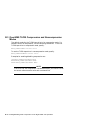
Product Notes for Novell NetWare and Microsoft Windows
NT . . . . . . . . . . . . . . . . . . . . . . . . . . . . . . . . . . . . . . . . . . .
Host SCSI Interface . . . . . . . . . . . . . . . . . . . . . . . . . . .
Product Notes for Sun . . . . . . . . . . . . . . . . . . . . . . . . . . . .
General Information . . . . . . . . . . . . . . . . . . . . . . . . . . .
Modifications Required for SunOS 4.1.x . . . . . . . . . . . .
Installation Procedure . . . . . . . . . . . . . . . . . . . . . .
System Modification . . . . . . . . . . . . . . . . . . . . . . . .
Rebuilding of Kernel . . . . . . . . . . . . . . . . . . . . . . .
Installation of Tape Drive . . . . . . . . . . . . . . . . . . .
Rebooting of System . . . . . . . . . . . . . . . . . . . . . . . .
Testing the Tape Drive . . . . . . . . . . . . . . . . . . . . . .
Verification . . . . . . . . . . . . . . . . . . . . . . . . . . . . . . .
.
.
.
.
.
.
.
.
.
.
.
.
.
.
.
.
.
.
.
.
.
.
.
.
.
.
.
.
.
.
.
.
.
.
.
.
.
.
.
.
.
.
.
.
.
.
.
.
.
.
.
.
.
.
.
.
.
.
.
.
C–1
C–1
C–3
C–3
C–4
C–4
C–4
C–5
C–6
C–6
C–6
C–7
vii
C.2.2.8
Dump Parameters for the Tape Drive . . . . . . . . . . . . . .
C.2.3
Modifications Required for Solaris 2.3 (or later) . . . . . . . . . .
C.2.3.1
Installation Procedure . . . . . . . . . . . . . . . . . . . . . . . . . .
C.2.3.2
System Modification . . . . . . . . . . . . . . . . . . . . . . . . . . . .
C.2.3.3
System Shutdown . . . . . . . . . . . . . . . . . . . . . . . . . . . . .
C.2.3.4
Installation of the Tape Drive . . . . . . . . . . . . . . . . . . . .
C.2.3.5
Rebooting of System . . . . . . . . . . . . . . . . . . . . . . . . . . . .
C.2.3.6
Test . . . . . . . . . . . . . . . . . . . . . . . . . . . . . . . . . . . . . . . .
C.2.3.7
Verification . . . . . . . . . . . . . . . . . . . . . . . . . . . . . . . . . . .
C.2.3.8
Dump Parameters for the Tape Drive . . . . . . . . . . . . . .
C.3
Product Notes for IBM RS/6000 . . . . . . . . . . . . . . . . . . . . . . . . .
C.3.1
Modifications Required to Operate the Tape Drive with AIX
3.2.5 (or later) . . . . . . . . . . . . . . . . . . . . . . . . . . . . . . . . . . .
C.3.1.1
Installing the Tape Drive Using the SMIT Command . .
C.3.1.2
Installing the Tape Drive Using Command-Line
Interface . . . . . . . . . . . . . . . . . . . . . . . . . . . . . . . . . . . . .
C.3.2
Using the Tape Drive to Install AIX . . . . . . . . . . . . . . . . . .
C.4
Product Notes for Hewlett-Packard . . . . . . . . . . . . . . . . . . . . . .
C.4.1
General Information . . . . . . . . . . . . . . . . . . . . . . . . . . . . . . .
C.4.2
Modifications Required . . . . . . . . . . . . . . . . . . . . . . . . . . . .
C.4.2.1
Installation Procedure . . . . . . . . . . . . . . . . . . . . . . . . . .
C.4.2.2
Installation of Tape Drive . . . . . . . . . . . . . . . . . . . . . . .
C.4.2.3
System Modification . . . . . . . . . . . . . . . . . . . . . . . . . . . .
C.4.2.4
System Device Files . . . . . . . . . . . . . . . . . . . . . . . . . . . .
C.4.2.5
HP-UX 9.05 . . . . . . . . . . . . . . . . . . . . . . . . . . . . . . . . . .
C.4.2.6
HP-UX 10.x . . . . . . . . . . . . . . . . . . . . . . . . . . . . . . . . . .
C.4.3
Testing the Tape Drive . . . . . . . . . . . . . . . . . . . . . . . . . . . .
C.4.3.1
Verification . . . . . . . . . . . . . . . . . . . . . . . . . . . . . . . . . .
C.4.3.2
Dump Parameters for the Tape Drive . . . . . . . . . . . . . .
.
.
.
.
.
.
.
.
.
.
.
C–7
C–7
C–7
C–8
C–9
C–9
C–10
C–11
C–11
C–11
C–12
.
.
C–12
C–12
.
.
.
.
.
.
.
.
.
.
.
.
.
.
C–13
C–14
C–15
C–15
C–15
C–16
C–16
C–16
C–16
C–17
C–18
C–19
C–19
C–20
.
.
.
.
.
.
.
1–4
1–5
1–6
1–7
3–3
3–5
5–6
Index
Figures
1–1
1–2
1–3
1–4
3–1
3–2
5–1
viii
Model TLZ09-DA/DB (Tabletop) . . . . . . . . . .
Model TLZ09-AA/AB (3.5-inch Chassis) . . . .
Model TLZ09-BA/BB (5.25-Inch Chassis) . . .
TLZ09 Chassis–Underside with Switch Pack
Configuration Jumper Block . . . . . . . . . . . .
Drive Switch Settings . . . . . . . . . . . . . . . . .
TLZ09 Cassette Tape . . . . . . . . . . . . . . . . . .
.
.
.
.
.
.
.
.
.
.
.
.
.
.
.
.
.
.
.
.
.
.
.
.
.
.
.
.
.
.
.
.
.
.
.
.
.
.
.
.
.
.
.
.
.
.
.
.
.
.
.
.
.
.
.
.
.
.
.
.
.
.
.
.
.
.
.
.
.
.
.
.
.
.
.
.
.
.
.
.
.
.
.
.
7–1
7–2
7–3
7–4
7–5
7–6
7–7
7–8
7–9
7–10
Model TLZ9L-AA (Front and Bottom View) . . .
Model TLZ9L-DA/DB (Front and Rear View) . .
TLZ9L LCD Panel . . . . . . . . . . . . . . . . . . . . . .
TLZ9L Cassette Magazine . . . . . . . . . . . . . . . .
Eight Cartridge Mode . . . . . . . . . . . . . . . . . . .
Seven Cartridge Mode . . . . . . . . . . . . . . . . . . .
Single Cartridge Mode . . . . . . . . . . . . . . . . . . .
Loading Cartridges Into the Magazine . . . . . . .
Loading the Magazine Into the TLZ9L-DA/DB
Unloading Cartridges From the Magazine . . . .
.
.
.
.
.
.
.
.
.
.
.
.
.
.
.
.
.
.
.
.
.
.
.
.
.
.
.
.
.
.
.
.
.
.
.
.
.
.
.
.
.
.
.
.
.
.
.
.
.
.
.
.
.
.
.
.
.
.
.
.
.
.
.
.
.
.
.
.
.
.
.
.
.
.
.
.
.
.
.
.
.
.
.
.
.
.
.
.
.
.
.
.
.
.
.
.
.
.
.
.
.
.
.
.
.
.
.
.
.
.
7–3
7–4
7–5
7–7
7–10
7–11
7–12
7–13
7–14
7–16
SCSI ID Jumper Settings (0=Removed, 1=Installed)
TLZ09 LED Status . . . . . . . . . . . . . . . . . . . . . . . . . .
Problem Solving . . . . . . . . . . . . . . . . . . . . . . . . . . . .
BUSY and TAPE LEDs Status . . . . . . . . . . . . . . . . .
Warning Indications . . . . . . . . . . . . . . . . . . . . . . . . .
Error Indications . . . . . . . . . . . . . . . . . . . . . . . . . . .
Switchpack Settings . . . . . . . . . . . . . . . . . . . . . . . . .
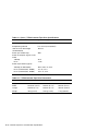
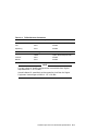
TLZ09 Cassette Tape Drive Specifications . . . . . . . .
TLZ09 Cassette Tape Drive Dimensions . . . . . . . . .
TLZ09-DA Noise Declaration . . . . . . . . . . . . . . . . . .
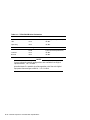
TLZ9L Cassette Tape Autoloader Specifications . . . .
TLZ9L Cassette Tape Autoloader Dimensions . . . . .
TLZ9L-DA/DB Noise Declaration . . . . . . . . . . . . . . .
.
.
.
.
.
.
.
.
.
.
.
.
.
.
.
.
.
.
.
.
.
.
.
.
.
.
.
.
.
.
.
.
.
.
.
.
.
.
.
.
.
.
.
.
.
.
.
.
.
.
.
.
.
.
.
.
.
.
.
.
.
.
.
.
.
.
.
.
.
.
.
.
.
.
.
.
.
.
.
.
.
.
.
.
.
.
.
.
.
.
.
3–3
5–2
6–3
7–2
7–6
7–8
7–17
A–1
A–2
A–3
A–4
A–5
A–6
Tables
3–1
5–1
6–1
7–1
7–2
7–3
7–4
A–1
A–2
A–3
A–4
A–5
A–6
ix
1
TLZ09/9L Cassette Tape Device Product
Description
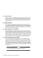
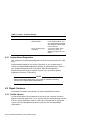
1.1 Overview
The TLZ09/9L Digital Audio Tape (DAT) device provides you with high
capacity, off-line data storage. Depending on the 4 mm data cassette tape used,
the unit can typically store the following amount of data on each tape:
Tape Type (NOTES 1 and 2)
No Compression
Compression
TLZ04-CA (60 m, DDS-1)
1.3 GB
2.6 GB (see Note 3.)
TLZ06-CA (90 m, DDS-1)
2.0 GB
4.0 GB (see Note 3.)
TLZ07-CA (120 m, DDS-2)
4.0 GB
8.0 GB (see Note 3.)
NOTE
1. The TLZ09/9L is compatible with 60 m cassette tapes written on the
TLZ04 in the noncompressed mode only.
2. The TLZ09/9L is compatible with the TLZ06/6L using 60 m and 90
m tapes only, and with the TLZ07/7L using 60 m, 90 m, and 120 m
tapes.
3. The compression measurements are typical for a 2-to-1 data
compression ratio, but the actual ratio is dependent on the data.
The maximum time to back up (read or write) on a TLZ09/9L cassette tape
in a continual (streaming) mode is system dependent. The efficient use of
streaming mode is determined by your operating system. Please refer to your
system software documentation.
TLZ09/9L Cassette Tape Device Product Description 1–1
1.1.1 System Support
As of this printing, the TLZ09/9L device is supported by a variety of Digital
systems. Consult your Digital Sales Support representative for a list of
supported systems. Your particular system must have an available standard
SCSI (Small Computer System Interconnect) port in order to connect the
TLZ09 or TLZ9L.
1.2 Design Features
The TLZ09/9L cassette tape device uses state of the art technology. The
device’s design incorporates the Digital Data Storage (DDS) recording format
and Digital Audio Tape (DAT) recording technologies. It is also designed to
provide a transfer rate that is twice that of standard DDS-2 DAT drives while
still maintaining full DDS compatibility.
1.2.1 What is Digital Audio Tape (DAT)?
DAT technology provides a high recording density with a very low error rate
through the helical scan recording method. With this method of recording,
both the tape and the recording head move simultaneously. The read and write
heads are located on a rapidly rotating cylinder, or drum that is tilted at an
angle in relation to the vertical axis of the tape. This causes the tracks to be
recorded diagonally across the tape, resulting in an extremely high recording
density, far higher than what is achievable with stationary-head devices.
1.2.2 What is Digital Data Storage (DDS)?
DDS uses a recording format that supports the use of digital audio tape
for computer applications. The objectives of DDS are to maximize storage
capacity and performance, facilitate data interchange, and provide very fast
random access. In addition, this format has three levels of error correction,
which ensures high data integrity. The DDS-DC format, which is a superset
of the basic DDS DAT format, allows you to back up 8 gigabytes of data in
approximately 1.5 hours minimum with no operator intervention, assuming 2:1
compression ratio.
NOTE
Use of non-DDS media may result in degraded drive performance and
is not recommended by Digital Equipment Corporation.
1–2 TLZ09/9L Cassette Tape Device Product Description
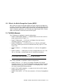
1.2.3 What is the Media Recognition System (MRS)?
MRS refers to a series of alternate opaque and clear stripes at the beginning
of a tape. This striping is used to classify the media as data grade rather than
audio grade media. Use of MRS helps to ensure that only data grade tapes are
used in computer applications. All 120-meter cartridges support MRS. Shorter
media are available in both MRS and non-MRS types.
1.3 TLZ09/9L Models
The TLZ09 drive is available in several configurations:
•
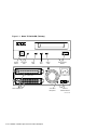
Model TLZ09-DA/DB (tabletop) — a compact external unit with a built-in
power supply and fan (Figure 1–1).
•
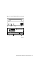
Model TLZ09-AA/AB — a 3 1/2-inch, half-height drive that mounts
internally (Figure 1–2 and Figure 1–4).
•
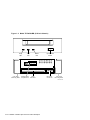
Model TLZ09-BA/BB — a 3 1/2-inch drive in a 5 1/4-inch, half-height
form factor allowing the drive to be mounted internally (Figure 1–3 and
Figure 1–4).
•
Model TLZ09-VA — a TLZ09-AA mounted in a 3 1/2-inch StorageWorks
SBB.
•
Model TLZ09-AX — a field spare unit that is configurable to an -AA, -AB,
-BA, or -BB model. Includes bezel and rail installation procedures.
NOTE
All the models have a drive buffer size of 1 MB of memory.
The TLZ9L autoloader is available in several configurations:
•
Model TLZ9L-AA — a 5 1/4-inch, full-height autoloader that mounts
internally (Figure 7–1). This unit comes with a light gray (DEC 217) bezel
installed and a dark gray (DEC 277) bezel in the shipping carton, along
with bezel removal/mounting procedures.
•
Model TLZ9L-DA/DB (tabletop) — an external unit with a built-in power
supply and fan (Figure 7–2).
•
Model TLZ9L-VA/VB — a TLZ9L-AA mounted in a 5 1/4-inch StorageWorks
SBB.
TLZ09/9L Cassette Tape Device Product Description 1–3
Figure 1–1 Model TLZ09-DA/DB (Tabletop)
On/Off
Switch
Power On
LED
Busy
LED
Tape
LED
Status
LED
SCSI CONNECTOR
Eject/Unload
Button
AC IN
- 0+
SCSI ID
SCSI Connectors
AC Power
Recepticle
GND
SCSI ID
Indicator/Switch
MLO-011795
1–4 TLZ09/9L Cassette Tape Device Product Description
Figure 1–2 Model TLZ09-AA/AB (3.5-inch Chassis)
Busy
LED
Tape
LED
Configuration
Jumper Block
Status
LED
SCSI
Connector
Eject/Unload
Button
DC Power
Connector
MLO-011796
TLZ09/9L Cassette Tape Device Product Description 1–5
Figure 1–3 Model TLZ09-BA/BB (5.25-Inch Chassis)
Busy
LED
5.25" Side
Mounting Rails
Tape
LED
Configuration
Jumper Block
Status
LED
SCSI
Connector
Eject/Unload
Button
DC Power
Connector
5.25" Side
Mounting Rails
MLO-011797
1–6 TLZ09/9L Cassette Tape Device Product Description
Figure 1–4 TLZ09 Chassis–Underside with Switch Pack
Drive Mode TLZ09 (Off)
MRS Detect Disabled (Off)
Self Test Enabled (Off)
Reserved (Off)
On
Off
1
2
3
4
MLO-011799
TLZ09/9L Cassette Tape Device Product Description 1–7
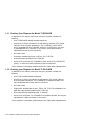
1.3.1 Checking Your Shipment for Model TLZ09-DA/DB
In addition to this manual, make sure that your shipment includes the
following:
•
One TLZ09-DA/DB tabletop cassette tape drive
•
One 50-pin to 50-pin (low density to high density connector) SCSI signal
cable for drive to system connections. PN 17-04356-01 is frost white
and is packaged with the TLZ09-DB, while PN 17-03742-09 is gray and
is packaged with the TLZ09-DA. In the future, black cables may be
substituted for both of these variations.
•
AC power cable
•
One blank cassette tape (4 mm x 120 m), (PN TLZ07-CA)
•
One head cleaning cassette (PN TLZ04-HA)
•
Active SCSI terminator [PN 12-44026-01 (frost white) or PN 12-41807-01
(gray)]. In the future, black terminators may be substituted.
If your shipment is incomplete, please contact your Digital sales representative.
1.3.2 Checking your Shipment for Model TLZ9L-DA/DB
In addition to this manual, make sure that your shipment includes the
following:
•
One TLZ9L-DA/DB tabletop autoloader
•
One 50-pin to 50-pin (low density to high density) SCSI signal cable for
drive to system connections. PN 17-04356-01 is shipped at present, but
may be replaced with a black cable in the future.
•
AC power cable
•
Eight blank cassette tapes (4 mm x 120 m, PN TLZ07-CA) preloaded in an
eight-slot tape cassette magazine (PN TLZ9L-08)
•
One head cleaning cassette tape (PN TLZ04-HA)
•
Active SCSI terminator. PN 12-44026-01 is shipped at present, but may be
replaced with a black terminator in the future.
If your shipment is incomplete, please contact your Digital sales representative.
1–8 TLZ09/9L Cassette Tape Device Product Description
1.3.3 Ordering Additional Cassettes
To order additional blank cassette tapes and head cleaning cassettes, contact
your Digital sales representative or DECdirect. Refer to the following part
numbers.
•
Five blank cassette tapes (4 mm x 60 m) (PN TLZ04-CB)
•
Five blank cassette tapes (4 mm x 90m) (PN TLZ06-CB)
•
Five blank cassette tapes (4 mm x 120m) (PN TLZ07-CB)
•
One head cleaning cassette (PN TLZ04-HA)
TLZ09/9L Cassette Tape Device Product Description 1–9
2
Installing the Tabletop Drive or Autoloader
(TLZ09-DA/DB or TLZ9L-DA/DB)
2.1 General
This chapter shows you how to install the TLZ09-DA/DB tabletop cassette
tape drive or TLZ9L-DA/DB tabletop cassette tape autoloader on systems
with an external SCSI connector. Read the following sections to complete the
installation.
2.2 Shut Down, Halt, and Power Off the System
If you are installing a TLZ09-DA/DB tabletop cassette tape drive or a TLZ9LDA/DB tabletop cassette tape autoloader on a running system, have your
system manager perform the following steps:
1. Shut down the operating system.
2. Halt the system.
3. Set all system power switches off.
Installing the Tabletop Drive or Autoloader (TLZ09-DA/DB or TLZ9L-DA/DB) 2–1
2.3 Selecting the SCSI Address
To familiarize yourself with the TLZ09 drive and TLZ9L autoloader:
1. Refer to Figure 1–1 for the location of the buttons, switches, and connectors
on the tabletop drive and to Figure 7–2 for the location of the buttons,
switches, and connectors on the tabletop autoloader.
2. Note that all connections are made at the rear of the tabletop enclosure.
Your system uses a SCSI ID switch to identify, or address, the drive. The SCSI
ID is factory set at 0. If you are installing the drive on a system that is already
using SCSI ID 0, use any available SCSI ID. (You may have to consult your
system manager.)
To set/change the SCSI address:
1. Locate the SCSI address switch at the rear of the tabletop enclosure.
2. Select the SCSI address for the drive or autoloader. Press the + or button until the desired address (0 through 7) appears in the window. See
Figure 1–1 for the drive and Figure 7–2 for the autoloader.
NOTE
If you are installing any other drive variant, refer to Chapter 3.
Turn off all power before connecting the cables and the terminator.
The drive must be turned off and then on for switch settings to take
effect, or a SCSI bus reset must be received.
2–2 Installing the Tabletop Drive or Autoloader (TLZ09-DA/DB or TLZ9L-DA/DB)
The tabletop devices provide two SCSI connectors to allow daisy chaining.
Either connector can connect to the host computer or any SCSI device in a
daisy chain.
•
If the tabletop is the last device in the chain an interface cable is attached
to one connector and an active SCSI terminator is installed in the other
connector.
•
If the device is within the chain, the interface cable from the preceding
device is connected in one connector; an interface cable is also connected
from the other connector to the following device.
NOTE
Make sure that the last SCSI device on the bus is terminated correctly
and is jumpered to supply termination power
2.4 Connecting a SCSI Signal Cable — Device to System
If you are connecting a TLZ09-DA/DB drive or TLZ9L-DA/DB
autoloader directly to your system, you should use the SCSI signal
cable supplied as part of your system installation kit.
If you do not have this cable, contact your Digital sales representative. You
should use a cable supplied by Digital Equipment Corporation. Failure to do
so can result in degraded performance of your tabletop device.
To connect a SCSI cable — device to system — perform the following:
1. Connect one end of the cable to the system SCSI connector.
2. Connect the other end of the SCSI signal cable to either SCSI connector on
the rear of the TLZ09-DA/DB drive or TLZ9L-DA/DB autoloader.
3. Secure the SCSI cable by snapping the wire cable clamps (on either side of
the SCSI connector) into place.
4. Connect the SCSI terminator to the other SCSI connector on the rear of
the TLZ09-DA/DB drive or TLZ9L-DA/DB autoloader.
5. Secure the terminator by snapping the wire cable clamps (on either side of
the SCSI connector) into place.
Installing the Tabletop Drive or Autoloader (TLZ09-DA/DB or TLZ9L-DA/DB) 2–3
2.5 Adding Another Tabletop Device — Device to Device
If you have one SCSI tabletop device already connected to your system, you
can connect the TLZ09-DA/DB drive or the TLZ9L-DA/DB autoloader to that
device. For device to device connections, use a 50-pin low density to 50-pin low
density SCSI signal cable [PN 17-03926-02 (gray), 17-04370-01 (frost white), or
equivalent].
Care should be taken to ensure that total SCSI cable length is well within the
SCSI specification limit of 6 meters for 5 MB/s transfer speeds (including cable
length within the system enclosure). When operating at FAST SCSI (10 MB/s)
transfer speeds, the total cable length must not exceed 3 meters. It is also
important to ensure that the drive is configured to supply terminator power to
the bus (default configuration). See Chapter 3 or Chapter 7 for jumper/switch
configurations.
1. If present, remove the SCSI terminator from the existing SCSI drive.
2. Connect one end of the SCSI signal cable (see part numbers above) to
the existing SCSI device, observing the correct orientation of the cable
connector.
3. Secure the SCSI cable by snapping the wire cable clamps (on either side of
the SCSI connector) into place.
4. Connect the other end of the SCSI signal cable to either SCSI connector on
the TLZ09-DA/DB drive or TLZ9L-DA/DB autoloader, observing the correct
orientation of the cable connector.
5. Secure the SCSI cable by snapping the wire cable clamps (on either side of
the SCSI connector) into place.
6. Connect the SCSI terminator to the other SCSI connector on the TLZ09DA/DB drive or TLZ9L-DA/DB autoloader, observing the correct orientation
of the cable connector.
2–4 Installing the Tabletop Drive or Autoloader (TLZ09-DA/DB or TLZ9L-DA/DB)
2.6 Connecting the Power Cable
The tabletop devices have an autoranging power supply. Refer to Table A–1 or
Table A–4 for voltage specifications.
To connect the power cable, proceed as follows:
1. Be sure that the TLZ09-DA/DB drive or TLZ9L-DA/DB autoloader power
switch is off (0).
2. Connect the power cable to the TLZ09-DA/DB drive or TLZ9L-DA/DB
autoloader power connector.
3. Connect the other end of the power cable to a nearby ac outlet.
NOTE
Multivendor Customer Services personnel: The power cable disconnects
the device from the main ac power source.
Proceed to Chapter 4.
Installing the Tabletop Drive or Autoloader (TLZ09-DA/DB or TLZ9L-DA/DB) 2–5
3
Installing the TLZ09-AA/AB, -BA/BB
Cassette Tape Drive
3.1 General
This chapter shows you how to install the TLZ09-AA/AB 3.5-inch and TLZ09BA/BB 5.25-inch form factor) cassette tape drives in a system enclosure
or external expansion box. Read the following sections to complete the
installation.
3.2 Shut Down, Halt, and Power Off the System
If you are installing a TLZ09 drive on a running system, have your system
manager perform the following steps:
1. Shut down the operating system.
2. Halt the system.
3. Set all system power switches off.
Installing the TLZ09-AA/AB, -BA/BB Cassette Tape Drive 3–1
3.3 Selecting the Jumper and Switch Configuration for the
TLZ09-AA/AB, -BA/BB Drive
To familiarize yourself with the TLZ09 drive:
1. Refer to Figures 1–2 through 1–4 for the location of the buttons, switches,
and connectors on the TLZ09 drive.
2. Note that all connections are made at the rear of the drive.
3.3.1 SCSI ID Address Jumpers
Your system uses a SCSI ID jumper block to identify, or address, the TLZ09.
The SCSI ID is factory set at 0. If you are installing the TLZ09 on a system
that is already using SCSI ID 0, use any available SCSI ID. (You may have to
consult your system manager.)
To set/change the SCSI address, refer to Figure 1–2 and Figure 3–1 for jumper
block location, then:
1. Refer to Figure 3–1 for jumper configuration.
2. Select a unique address number with the first three jumpers on the left.
Table 3–1 shows the SCSI IDs (0 through 7) and Figure 3–1 shows a close-up
view of the jumpers.
NOTE
If you are installing the tabletop variant, refer to Chapter 2.
Turn off all power before connecting the cables.
The drive must be power cycled for switch settings to take effect, or a
SCSI bus reset must be received.
NOTE
Make sure that both ends of the SCSI bus are terminated correctly. For
the drive, termination is enabled by installing a jumper on pins 13 and
14 of the jumper block.
3–2 Installing the TLZ09-AA/AB, -BA/BB Cassette Tape Drive
Table 3–1 SCSI ID Jumper Settings (0=Removed, 1=Installed)
SCSI ID
Pins 1
and 2
Pins 3
and 4
Pins 5 and 6
0
0
0
0 (default setting)
1
0
0
1
2
0
1
0
3
0
1
1
4
1
0
0
5
1
0
1
6
1
1
0
7
1
1
1
Figure 3–1 Configuration Jumper Block
SCSI ID 2
SCSI ID 1
SCSI ID 0
Data Compression Enabled
1
3
5
7
9
11 13
15
2
4
6
8
10 12 14
16
Terminator Power Enabled
Termination Disabled
Reserved
SCSI Parity Enabled
MLO-011798
NOTE
The drive must be powered down and then powered up for new jumper
settings to take effect.
Installing the TLZ09-AA/AB, -BA/BB Cassette Tape Drive 3–3
3.3.2 Other Optional Jumper Settings
The remaining jumpers allow you to set up the following configuration options:
•
Parity enable/disable (jumper 9–10): Default = parity enabled (jumper
installed on pins 9–10)
•
Compression enable/disable at power up (jumper 7–8): Default =
compression enabled at power up (jumper removed from pins 7–8)
•
Termination enable/disable (jumper 13–14): Default = termination disabled
(jumper removed from pins 13–14)
•
Terminator power enable/disable (jumper 15–16): Default = terminator
power enabled (jumper installed on pins 15–16)
Figure 3–1 shows the default settings for these jumpers.
NOTE
The drive must be turned off and then on for switch settings to take
effect, or a SCSI bus reset must be received.
Although jumper 7–8 is removed by default (compression enabled),
you may turn compression on and off with a software switch. Consult
Appendix B or Appendix C for the command format.
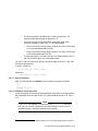
3.3.3 Drive Switch Settings
The drive switch (see Figure 3–2) allows you to configure the following options:
•
Drive Mode (S1): Switch defaults to off for TLZ09 mode (on indicates
generic mode)
•
Media Recognition System Detect Enable/Disable (S2): Switch defaults to
off for no MRS detection.
•
Self-Test Enable/Disable (S3): Switch defaults to off to enable diagnostic
self-test a power-up and reset.
•
Reserved (S4): This switch is reserved and should be in the off position.
3–4 Installing the TLZ09-AA/AB, -BA/BB Cassette Tape Drive
Figure 3–2 Drive Switch Settings
Drive Mode TLZ09 (Off)
MRS Detect Disabled (Off)
Self Test Enabled (Off)
Reserved (Off)
On
Off
1
2
3
4
MLO-011799
Installing the TLZ09-AA/AB, -BA/BB Cassette Tape Drive 3–5
3.4 Connecting a SCSI Signal Cable — Drive to System
If you are connecting a TLZ09 drive directly to your system, you
should use a SCSI signal cable supplied as part of your system
installation kit.
If you do not have this cable, contact your Digital sales representative. You
should use a cable supplied by Digital. Failure to do so can result in degraded
performance of your TLZ09 drive.
To connect a SCSI cable — drive to system — perform the following:
1. Connect one end of the cable to the system SCSI connector.
2. Connect the other end of the SCSI signal cable to the SCSI connector on
the rear of the TLZ09 drive (Figure 1–2 and Figure 1–3).
3.5 Connecting the Power Cable and Mounting
Connect the system internal power cable located at the rear of the drive
(Figure 1–2 and Figure 1–3).
NOTE
Multivendor Customer Services personnel: The power cable disconnects
the drive from dc power generated by the main ac power source.
3–6 Installing the TLZ09-AA/AB, -BA/BB Cassette Tape Drive
4
Verifying TLZ09 Cassette Tape Drive
Installation
4.1 General
To verify successful installation of the TLZ09 drive, execute the power-on
self-test (POST).
4.1.1 Execute POST
To execute POST:
1. For a tabletop unit, press the power switch to the on or | position
(Figure 1–1).
For a drive in a system enclosure, turn the system power source to the on
position.
2. Observe that after a two second delay, with no cassette in the drive, the
LEDs will flash off and on twice, followed by each LED lighting in a
sequence from left to right until the completion of self-tests.
With a cassette in the drive, the Tape and Busy indicators will continue
flashing (approximately 20 seconds) after completion of the above sequence
until the cassette is loaded.
3. After successful completion of POST, all LEDs will be extinguished. If
a cassette is loaded, the Tape LED will remain on. If the cassette is
write-protected, the Status LED will also remain on.
4. If the Status LED flashes twice every 1.25 seconds with the flashes
occuring close together followed by some delay, then POST failed. Attempt
to clear the failure by re-executing POST. (Power off and power on the
drive.) If the failure repeats itself, call Multivendor Customer Services.
Verifying TLZ09 Cassette Tape Drive Installation 4–1
After successful execution of POST, have your system manager restart the
system and assign a device name to your TLZ09 drive if necessary. Optionally,
you can run a full system or SCSI bus test. See your system owner’s manual
for specific instructions.
NOTE
If a tape is loaded, the Tape indicator stays on. If the tape is writeprotected, the Status indicator will also remain on.
4–2 Verifying TLZ09 Cassette Tape Drive Installation
5
Using the TLZ09 Cassette Tape Drive
5.1 General
This chapter shows you how to use the TLZ09 drives, buttons, and indicators
(Figures 1–1 through 1–3). It also shows you how to use cassette tapes.
5.2 Power Switch
For a tabletop unit, press the power switch to turn the TLZ09 drive on or off.
If you are not using the TLZ09 drive for prolonged periods of time, check with
your system manager for the correct procedure to shut down your system or
power off the drive.
5.3 Unload Button
Press and hold the unload button for 1 to 2 seconds to eject the cassette tape.
CAUTION
Pressing the unload button during normal tape operations may halt the
tape operation in progress.
5.4 Tape Drive LEDs
The Busy, Tape, and Status LEDs provide information on a variety of
operational conditions on the drive. Table 5–1 describes these indicators. The
LED color is amber for all three LEDs. See Figure 1–1 or Figure 1–2 for LED
locations on the bezel.
Using the TLZ09 Cassette Tape Drive 5–1
5.4.1 Status LED
This indicator comes on solid when the cassette is write-protected. It also has
other indications as documented in Table 5–1.
5.4.2 Tape LED
This indicator comes on solid when a cassette is loaded. It flashes during
loading and unloading. It also has other indications as documented in
Table 5–1.
5.4.3 Busy LED
This indicator comes on during SCSI, or drive activity. See also Table 5–1.
Table 5–1 TLZ09 LED Status
Condition
Busy LED
Tape LED
Status LED
No tape loaded
Off
Off
Off
Tape loaded,
write-enabled
Off
On
Off
Tape loaded,
write-protected
Off
On
On
No SCSI/Drive
activity
Off
Tape load status
Write-protect status
SCSI/Drive
activity
On during SCSI
activity, flashes
twice per second on
drive activity
Tape load status
Write-protect status
Load/Unload
sequence
Flashes twice per
second during
sequence, then
indicates activity
Flashes twice
per second, then
indicates either
tape loaded (on) or
unloaded (off)
Write-protect status
Reset sequence
Flashes on for 1
second
Off, then indicates
tape load status.
Off, then indicates
write-protect status.
(continued on next page)
5–2 Using the TLZ09 Cassette Tape Drive
Table 5–1 (Cont.) TLZ09 LED Status
Condition
Busy LED
Tape LED
Status LED
Power-on with
POST enabled
Off for two seconds,
then flashes twice
in one second.
Then flashes in
sequence with
Tape and Status
LEDs left to right.
This repeats until
self-tests complete.
Off for two seconds,
then flashes twice
in one second.
Then flashes in
sequence with
Busy and Status
LEDs, left to right.
This repeats until
self-tests complete.
Off for two seconds,
then flashes twice
in one second. Then
flashes in sequence
with Busy and Tape
LEDs, left to right.
This repeats until
self-tests complete.
Tests Complete,
No Failure
Normal operation
Normal operation
Normal operation
Self-Test failure
Not applicable
Not applicable
Flashes twice every
1.25 seconds with the
flashes occurring close
together, then some
delay.
Power-On with
POST disabled
Off for two seconds,
then flashes twice
in one second
Same as Busy
Same as Busy
Error Rate
Warning
Not applicable
One long flash
every four seconds.
Media may need
changing or drive
needs to be cleaned.
Not applicable
Drive mechanism failure
Not applicable
Not applicable
Flashes once every
1.25 seconds
Drive cleaning
request (timer
expired)
Not applicable
Not applicable
One long flash every
four seconds. Clean
drive.
Cleaning tape
inserted (good
tape)
Flashes twice per
second during
cleaning cycle,
then indicates
activity. On during
subsequent unload
sequence.
On
On if drive was not
requesting a cleaning.
One long flash every
four seconds if drive
was requesting a
cleaning cycle. On
during subsequent
unload sequence.
(continued on next page)
Using the TLZ09 Cassette Tape Drive 5–3
Table 5–1 (Cont.) TLZ09 LED Status
Condition
Busy LED
Tape LED
Status LED
Cleaning
tape inserted
(expired tape)
Off
On
Flashes twice per
second. Continues
until eject button is
pushed, at which time
a normal unload cycle
is initiated.
5–4 Using the TLZ09 Cassette Tape Drive
5.5 Using the Cassette Tape
Digital Equipment Corporation recommends that you use only DDS certified
tapes. The following sections describe how to:
•
Handle and store tape (Section 5.5.1)
•
Write-protect tape (Section 5.5.2)
•
Insert and remove tape (Section 5.5.3)
WARNING
Always place the tape label in the recessed area on the cassette. Never
place one label on top of another label.
NOTE
Use of non-DDS media may result in degraded drive performance. We
recommend the use of Digital Equipment Corporation media.
5.5.1 Proper Handling of Cassette Tapes
To ensure optimal performance from your cassette tapes, observe the following
guidelines when handling them.
•
Avoid placing the cassette tapes near sources of electromagnetic
interference, such as terminals, and video or X-ray equipment. Emissions
from such equipment can erase data on the tape.
•
Keep cassette tapes out of direct sunlight and away from heaters and other
sources of heat.
•
Store cassette tapes (and cleaning cassette) where the room temperatures
are between 5 and 32°C (40 and 90°F).
•
Store cassette tapes in a dust-free environment where the relative humidity
is 20 to 60% RH.
Using the TLZ09 Cassette Tape Drive 5–5
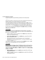
5.5.2 Setting the Write-Protect Tab on the Cassette Tape
If you are using the tape to read or are copying from the tape, we recommend
that you set the write-protect tab to write-protected. This disables writing
to tape, and ensures that data will not be accidentally overwritten. The
write-protect tab contrasts in color to the cartridge body. Use a pen (NOT A
PENCIL) to set the write-protect tab (Figure 5–1) to the desired position.
NOTE
The tab is not visible when the cassette tape is loaded in the TLZ09
drive.
Figure 5–1 TLZ09 Cassette Tape
WRITE-PROTECT
TAB
WRITE
PROTECTED ENABLED
WRITE
Observe the following guidelines when setting the write-protect tab.
•
If you are reading data (copying from the tape), set the write-protect tab to
write-protected by sliding the tab to the left.
•
If you are writing data, set the write-protect tab to write-enabled by sliding
the tab to the right.
•
The write-protect tab position is shown on the front panel Write-Protect
indicator.
5–6 Using the TLZ09 Cassette Tape Drive
5.5.3 Inserting a Cassette Tape into the Drive
Insert the TLZ09 cassette tape into the drive with the cassette’s write-protect
tab on the right, facing you. Remove the tape by depressing the tape eject
button.
CAUTION
The drive should never be transported with a tape loaded in the drive.
Tape damage and possible loss of data may result. Always unload the
tape prior to transporting the drive.
Using the TLZ09 Cassette Tape Drive 5–7
6
Preventive Maintenance and Problem
Solving
This chapter describes preventive maintenance and problem solving for the
TLZ09 cassette tape drive. Preventive maintenance involves periodic head
cleaning. Problem solving is described in Table 6–1.
Statistics show that over 90% of drive-related problems are associated with the
media. Therefore, Digital Equipment Corporation strongly recommends that
you follow the instructions for handling cassette tapes and cleaning the heads
of the drive.
6.1 Cleaning the Heads
This section shows you how to perform TLZ09 head cleaning. The heads are
the components that physically read and write data to and from the media (in
this case, a cassette tape).
Digital Equipment Corporation recommends that you perform the
head cleaning procedure after the first four hours of tape movement
with a new cartridge and thereafter once every 2 weeks, or after every
24 hours of drive usage, whichever comes first.
Under normal conditions, it should not be necessary to exceed this
cleaning schedule. If a particular data cassette causes problems, try
changing to another data cassette.
Preventive Maintenance and Problem Solving 6–1
CAUTION
Never attempt to clean the heads in a manner other than described.
Doing so will void the product warranty.
To clean the heads, use the head cleaning cassette as follows:
1. Apply power to the drive by pressing the power switch to the on position on
the system external storage expander box, the tabletop drive unit, or the
system enclosure for embedded drives.
2. Insert the head cleaning cassette (PN TLZ04-HA) into the drive.
3. With the head cleaning cassette inserted, the drive automatically
executes head cleaning. The drive ejects the head cleaning cassette
after approximately 30 seconds if head cleaning is successful.
4. On the card enclosed with the head cleaning cassette, record every time
you use the cassette.
Under normal conditions, the head cleaning cassette is used for about
25 cleanings. Additional cassettes are available from your Digital sales
representative or DECdirect.
If the number of cleaning cycles of a particular head cleaning cassette has
expired, the drive will signal the user by flashing the Status LED while the
Busy LED is off and the Tape LED is on (See Table 5–1). Press the eject
button to remove the cleaning cassette, as the drive will not automatically
eject an expired cleaning cartridge. No cleaning action will have occurred.
6–2 Preventive Maintenance and Problem Solving
6.2 Problem Solving
Table 6–1 describes drive problems and possible solutions. See also Table 5–1.
Table 6–1 Problem Solving
Symptom
Probable Cause
Possible Solution
Unable to back up or copy
data to cassette tape.
Cassette writeprotected.
1. Set write-protect tab on
cassette to write-enabled.
No tape in drive.
2. Insert tape.
Dirty head or bad
media.
3. Clean head or replace
media.
Tape LED flashes twice per
1.25 seconds with flashes
occurring close together.
Error rate warning
Perform head cleaning
procedure (see Section 6.1).
If error repeats, try another
tape.
Status LED flashes once
every four seconds.
Cleaning interval
timer expired.
Eject tape. Perform head
cleaning procedure (see
Section 6.1).
Status LED flashes once
every 1.25 seconds.
Drive mechanism
failure
Eject tape. Power off and
power on the drive. If error
repeats, call Multivendor
Customer Services.
After applying power and
self-test has completed
successfully, the Tape LED is
not lit.
No tape loaded.
Load tape.
Drive not available to system.
Drive not plugged in.
1. Make sure power cable is
plugged in and check power.
SCSI ID jumpers set to
incorrect address.
2. Check SCSI ID jumpers.
Defective SCSI cable.
3. Be sure SCSI cable
connections are secure.
Incorrect termination,
or no term power
4. Verify termination and
that term power is being
supplied to both ends of the
bus.
Dirty head or worn
media.
1. Clean heads or replace
media.
Poor performance or low
capacity.
(continued on next page)
Preventive Maintenance and Problem Solving 6–3
Table 6–1 (Cont.) Problem Solving
Symptom
Probable Cause
Possible Solution
Operating in nonbuffered mode.
2. Host is putting the drive
in non-buffered mode. Use
SCSI Mode Select command
with buffered mode enabled
in host software.
Drive not being kept
streaming.
3. Too much other sytem
activity in process, or
dumping to tape from slow
device.
6.2.1 System-Based Diagnostics
Your system has system-based diagnostics that can be used to test the TLZ09
drive.
System-based diagnostics are usually referred to in your system owner’s
manual as console-based diagnostics, self-tests, or system exercisers. Refer to
your system documentation for information about these diagnostics.
Before calling Multivendor Customer Services, you can execute system
diagnostics to test the TLZ09 drive.
NOTE
Some system-based diagnostics are subject to software licensing.
Consult your Digital sales representative.
6.3 Repair Services
Multivendor Customer Services offers a range of flexible service plans.
6.3.1 On-Site Service
On-site service offers the convenience of service at your site and insurance
against unplanned repair bills. For a monthly fee, you receive personal service
from our service specialists. Within a few hours, the specialist is dispatched
to your site with equipment and parts to give you fast and dependable
maintenance.
6–4 Preventive Maintenance and Problem Solving
6.3.2 BASIC Service
BASIC Service offers full coverage from 8 a.m. to 5 p.m., Monday through
Friday. Options are available to extend your coverage to 12-, 16- or 24-hour
periods, and to include Saturdays, Sundays, and holidays. Under the BASIC
service plan all parts, materials and labor are covered in full.
6.3.3 DECservice
DECservice offers a premium, on-site service for committed response to
remedial service requests made during contracted hours of coverage. Remedial
maintenance will be performed continuously until the problem is resolved,
which makes this service ideal for customers requiring maximum service
performance. Under DECservice all parts, materials, and labor are covered in
full.
6.3.4 Carry-In Service
Carry-in service offers fast, personalized response, and the ability to plan your
maintenance costs for a smaller monthly fee than on-site service. When you
bring your unit to one of the many Digital SERVICenters worldwide, factorytrained personnel repair your unit within 2 days. This service is available on
selected terminals and systems. Contact your local unit. Digital SERVICenters
are open during normal business hours, Monday through Friday.
6.3.5 DECmailer Service
DECmailer offers expert repair at a per use charge. This service is designed
for users who have the technical resources to troubleshoot, identify, and isolate
the module causing the problem. Mail the faulty module to our Customer
Returns Center where the module is repaired and mailed back to you within 5
days.
6.3.6 Per Call Service
Per call service offers a maintenance program on a noncontractual, time-andmaterials-cost basis. It is appropriate for customers who have to perform
first-line maintenance, but may occasionally need in-depth support from
Multivendor Customer Services.
Preventive Maintenance and Problem Solving 6–5
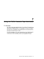
7
Using the TLZ9L Cassette Tape Autoloader
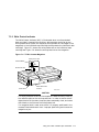
7.1 Overview
The TLZ9L cassette tape autoloader (Figure 7–1 and Figure 7–2) provides very
high capacity unattended backup, as well as support for the full random access
command set as defined by SCSI-2. It is packaged in a 5 1/4-inch, full-height
form factor with an embedded TLZ09 cassette tape drive, and provides all the
functionality and features of the TLZ09.
The TLZ9L autoloader is NOT a field upgrade option for the TLZ09 tape drive.
It must be purchased as a single unit. With the 8-cartridge magazine (PN
TLZ9L-08), the TLZ9L autoloader provides up to 64 gigabytes of storage.
Using the TLZ9L Cassette Tape Autoloader 7–1
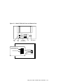
7.2 LED Indicators
The basic TLZ9L autoloader has two LEDs labeled BUSY and TAPE. The
tabletop TLZ9L autoloader has an additional LED indicator labeled POWER
which illuminates when power is applied.
The status of the BUSY and TAPE LEDs during various conditions is described
in Table 7–1.
Table 7–1 BUSY and TAPE LEDs Status
Condition
BUSY LED Status
TAPE LED Status
Idle
OFF
N/A
SCSI active
Steady green
N/A
Drive active
Flashing green
N/A
Write in progress
Flashing amber
Steady green
Firmware upgrade in
progress
Flashing amber
Flashing amber
No cartridge in drive
N/A
OFF
Cartridge in drive
N/A
Steady green
Loading or unloading
N/A
Flashing green
7–2 Using the TLZ9L Cassette Tape Autoloader
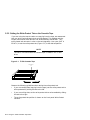
Figure 7–1 Model TLZ9L-AA (Front and Bottom View)
BUSY
WP
1 2 3 4
5 6 7 C
TAPE
Busy
LED
Tape
LED
EJECT
SELECT
Cartridge
Select Button
Continuous-Cycle
Mode Disabled (ON)
LCD
Eject Button
4
3
Reserved (ON)
2
1
On
MLO-013654
Using the TLZ9L Cassette Tape Autoloader 7–3
Figure 7–2 Model TLZ9L-DA/DB (Front and Rear View)
Magazine Door
Power On LED
POWER
BUSY
WP
1 2 3 4
5 6 7 C
TAPE
Power
Switch
Busy
LED
Tape
LED
EJECT
SELECT
Cartridge
LCD
Select Button
Eject Button
SCSI CONNECTOR
SCSI ID
0
AC IN
GND
SCSI Connectors
SCSI ID
Switch
Ground
Connection
AC Receptacle
Cooling
Fan
MLO-013655
7–4 Using the TLZ9L Cassette Tape Autoloader
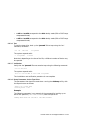
7.3 LCD Panel
The liquid crystal display (LCD) panel on the TLZ9L autoloader contains five
separate indicators that provide status as well as error information to the user
(see Figure 7–3).
Figure 7–3 TLZ9L LCD Panel
Error Indicator
Warning Indicator
Write-Protect
Indicator
7-Segment Numeric
Indicator
WP
1 2 3 4
5 6 7 C
Cartridge Number
Indicator
MLO-013656
Using the TLZ9L Cassette Tape Autoloader 7–5
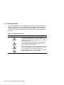
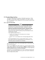
7.3.1 Warning Indicator
The warning indicator is illuminated upon occurrence of a warning condition.
When this indicator is lit in combination with a number in the 7-segment
display, a particular warning or caution can be indicated. Table 7–2 lists the
warning and numeric combinations with a description of what they indicate
when lit.
Table 7–2 Warning Indications
Indicator and Number
1
Indication
Indicates a cleaning request. (Drive needs cleaning.)
Illuminated upon expiration of a 24 hour timer as well as
with the occurrence of certain medium errors. Insert the
cleaning tape to clear.
2
End of tape reached during cleaning. Cleaning did not
occur. Discard the cleaning tape, replace with a new
cleaning tape, and retry cleaning.
3
DDS cartridge loaded with incorrect orientation or slide
shutter is positioned incorrectly. Remove all cartridges
from the magazine, then reload them correctly.
4
Magazine does not contain correct number of cartridges.
Reload magazine with 1, 7, or 8 cartridges.
7–6 Using the TLZ9L Cassette Tape Autoloader
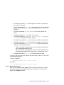
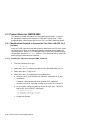
7.3.2 Write Protect Indicator
The Write-Protect indicator (WP) is illuminated when a write-protected
data cartridge is inserted into the drive. Write-protect can be set by the
write-protect tab on either the magazine (write-protects all cartridges in the
magazine) or the individual tape cartridge (write-protects the individual data
cartridge). Figure 5–1 shows the write-protect tab on the individual tape
cartridge and Figure 7–4 shows the write-protect tab on the magazine.
Figure 7–4 TLZ9L Cassette Magazine
Write-protect Tab
Write Enabled
SAVE
REC
SAVE
Write Protected
REC
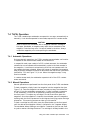
Slide Latch
Label Attachment
Position
MLO-013657
CAUTION
The write protection status of the magazine is determined by checking
the reflective plate on the write-protect tab. In order to ensure correct
determination of the status, keep the plate reasonably clean, and never
affix labels or the like over the write-protect tab.
If a magazine label is used, ensure that it is properly positioned in the
recessed "label attachment area." Improper positioning could cause the
magazine to jam.
Using the TLZ9L Cassette Tape Autoloader 7–7
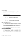
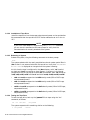
7.3.3 Error Indicator
The error indicator is illuminated when certain errors occur. When this
indicator is lit in combination with a number in the 7-segment display, a
particular error can be indicated. Table 7–3 lists the error and numeric
combinations with a description of what they indicate when lit.
Table 7–3 Error Indications
Indicator and Number
Error Message
1
Loader mechanism error. Call service personnel.
2
Embedded drive error. Call service personnel.
3
Media error. Replace tape cartridge.
4
Cartridge stuck in the drive. Call service personnel.
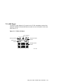
7.3.4 7-Segment Numeric Display
The 7-segment display normally displays the number of the data cartridge that
is currently loaded in the drive.
When the Select button is pushed, this 7-segment display shows the number
of the cartridge that has been selected. After 5 seconds, the selected cartridge
will be loaded into the drive.
When either the Warning or Error indicators are lit, the 7-segment display
indicates the specific type of warning or error (see Table 7–2 and Table 7–3).
7.3.5 Cartridge Number Indicators
The eight boxes at the bottom of the LCD panel are individually lit to indicate
which slots in the magazine contain cartridges. The boxes will blink to indicate
that a cartridge is being loaded. A box that is not lit indicates that a cartridge
is not in that slot of the magazine (for example, the cartridge is loaded in the
drive). The box will become lit again once the cartridge is returned to that slot
in the magazine.
7–8 Using the TLZ9L Cassette Tape Autoloader
7.4 TLZ9L Operation
The TLZ9L cassette tape autoloader can operate in two ways; automatically or
manually. It can also be operated in two modes; sequential or random access.
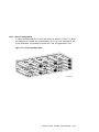
CAUTION
Never transport the autoloader with a magazine installed. Damage to
the tapes, autoloader, or magazine may result due to movement of the
magazine. Data loss may occur if a tape is loaded in the drive. Always
unload the magazine prior to transporting the autoloader.
7.4.1 Automatic Operations
During automatic operations, the TLZ9L cassette tape autoloader can function
in sequential and random access modes at the same time.
In sequential mode, upon receipt of a SCSI unload command, the autoloader
unloads the current cassette and automatically cycles to the next cassette in
the magazine. It continues to unload and cycle to the next cassette until the
last cassette has been unloaded. When this process is complete, the magazine
stops to prevent accidental overwrite of data unless the continuous cycle switch
(see Section 7.5.1 and Figure 7–1) is set. When the magazine stops, it may
then be unloaded.
In random access mode, the autoloader responds to all of the SCSI random
access commands.
7.4.2 Manual Operations
Manual operations are performed from the front panel of the TLZ9L autoloader.
To load a magazine, simply insert the magazine into the magazine door (see
Figure 7–9). Once the magazine has been inserted part way, the mechanism
will pull it into the autoloader automatically. If there is already a magazine
in the autoloader, it must first be ejected by pressing the Eject button on
the front panel. This ejects any cartridge in the drive and then ejects the
magazine. Once the magazine is inserted, the autoloader scans the magazine
checking each slot for the presence of a cartridge and verifying proper cartridge
orientation. This scanning process can take up to 90 seconds.
To load a cartridge into the drive, press the Select button on the front panel
until the desired cartridge/slot number is indicated in the 7-segment display.
The autoloader delays loading a cartridge for 5 seconds to give the user time
to cycle to another cartridge if desired. If a cartridge is already loaded in the
Using the TLZ9L Cassette Tape Autoloader 7–9
drive, the autoloader will unload that cartridge, place it back in the magazine,
and then load the selected cartridge.
7.4.3 Magazine Operations
The TLZ9L cassette tape autoloader supports three basic magazine
configurations. These configurations are 8, 7, and single-cartridge modes.
Any other number of cartridges is not supported and will cause the magazine
to eject. See Section 7.4.3.4 for the procedure on loading cartridges into the
magazine and Section 7.4.3.7 for the procedure on unloading cartridges from
the magazine.
7.4.3.1 Eight Cartridge Mode
In eight cartridge mode the magazine accommodates either eight data
cartridges or seven data cartridges and one cleaning cartridge. The sequence
in which the cartridges are inserted into the magazine determines the numbers
by which they are managed as indicated in Figure 7–5. The letter C indicates
the cleaning cartridge. If a cleaning cartridge is not used, the C slot can be
populated with the eighth data cartridge to provide the highest capacity per
magazine.
Figure 7–5 Eight Cartridge Mode
5
6
4
7
3
8
C or
2
1
MLO-013658
7–10 Using the TLZ9L Cassette Tape Autoloader
7.4.3.2 Seven Cartridge Mode
In seven cartridge mode the C slot is left vacant as shown in Figure 7–6. When
the magazine is inserted into the autoloader, the C slot is not available for use
by the autoloader. Any attempt to access the C slot will generate an error.
Figure 7–6 Seven Cartridge Mode
5
6
C or 8
4
7
3
2
1
MLO-013659
Using the TLZ9L Cassette Tape Autoloader 7–11
7.4.3.3 Single Cartridge Mode
In single cartridge mode, either a data cartridge or a cleaning cartridge is
inserted into the C slot position of the magazine as shown in Figure 7–7. When
the magazine is inserted into the autoloader, the cartridge is automatically
loaded into the drive. When a cleaning cartridge is used, the magazine is
automatically ejected once the cleaning is completed.
Figure 7–7 Single Cartridge Mode
8
C or
MLO-013660
7–12 Using the TLZ9L Cassette Tape Autoloader
7.4.3.4 Loading Cartridges Into the Magazine
When loading data cartridges into the magazine, the bottom shelf of the
magazine should be loaded first. Ensure that the cartridges are oriented
correctly as shown in Figure 7–8. Load cartridge 3 in the bottom shelf
first, followed by cartridge 2 and then cartridge 1 in that order. It is highly
recommended that you number each cartridge by placing a numbered label on
the cartridges in order to keep track of each cartridge.
After loading the bottom shelf, start loading the top shelf of the magazine
beginning with cartridge 4 and proceeding with cartridge 5, cartridge 6, and
cartridge 7 in that order.
If either an 8th data cartridge or a cleaning cartridge is to be used, load it into
middle shelf of the magazine.
Figure 7–8 Loading Cartridges Into the Magazine
MLO-013661
Using the TLZ9L Cassette Tape Autoloader 7–13
7.4.3.5 Loading the Magazine Into the TLZ9L
To load a magazine into the TLZ9L cassette tape autoloader, first apply power
to the autoloader by powering on the system for an embedded autoloader,
or by pressing the power switch on the tabletop autoloader. The BUSY and
TAPE LED indicators blink as a self-test is performed. When the BUSY and
TAPE LED indicators stop blinking, the magazine can be inserted into the
autoloader as shown in Figure 7–9. When the magazine is inserted, the TAPE
LED indicator lights. If the magazine is write-protected, the write-protect (WP)
indicator also lights.
Once the magazine is inserted, the autoloader will cycle through and count
the cartridges in the magazine. If any of the cartridges are misoriented, or if
the number of cartridges present is other than 1, 7, or 8, the magazine will be
ejected. At the end of this initialization, if all of the cartridges are oriented
correctly and the correct number of cartridges are present, the autoloader goes
to the idle state. A cartridge can then be selected and loaded into the drive
either manually or through software control.
Figure 7–9 Loading the Magazine Into the TLZ9L-DA/DB
PO
WE
R
BU
TA
SY
SE
LE
CT
PE
EJ
EC
T
MLO-013662
7–14 Using the TLZ9L Cassette Tape Autoloader
7.4.3.6 Ejecting the Magazine
Under normal conditions, the magazine can be ejected by simply pressing the
Eject button on the front panel. Any cartridge that may be in the drive at the
time the Eject button is pressed will be rewound and unloaded back into the
magazine. The cartridges are then moved to their original locations within the
magazine and the magazine is ejected.
If the TLZ9L autoloader encounters a certain type of fatal error, you may not
be able to eject the magazine in a normal manner. However, you still may be
able to eject the magazine using an emergency eject. To invoke the emergency
eject, press and hold the Eject button for ten seconds while the error indication
is displayed in the 7-segment display. If a cartridge is stuck in the drive, the
magazine will be ejected without this cartridge being present. The LCD panel
will then indicate an error code of 4 and service personnel will need to be
called.
Using the TLZ9L Cassette Tape Autoloader 7–15
7.4.3.7 Unloading Cartridges From the Magazine
When unloading cartridges from a magazine, it is recommended that the
magazine be held over a table or bench so that the cartridges will fall gently to
the table top and not fall on the floor where they could be damaged.
Perform the unloading process by pressing down on the magazine slide latch
with the thumb of your left hand and then placing the finger of your right hand
in the hole at the rear of the magazine and pushing the cartridges toward the
front of the magazine (see Figure 7–10). Continue pushing the cartridges all
the way to the front of the magazine by using the slot in the bottom of the
magazine. This should remove the first five cartridges from the magazine.
Next, orient the magazine with the open end pointing upward and gently
tap the magazine against the palm of your hand. This moves the remaining
cartridges to the bottom shelf where they can be removed by following the
same procedure used for removing the first five cartridges.
Finally, the cartridge in the middle shelf can be removed by grasping it
with your thumb and index finger and pulling it out of the magazine while
continuing to press down on the magazine slide latch.
Figure 7–10 Unloading Cartridges From the Magazine
MLO-013663
7–16 Using the TLZ9L Cassette Tape Autoloader
7.5 Switch Settings
The following sections describe the switchpack settings on the TLZ9L
autoloader and the SCSI ID select switch on the TLZ9L-DA/DB autoloader.
It should be noted that all of the drive switches and jumpers still function as
documented in Chapter 3 for the drive mounted internal to the autoloader. For
example, to enable MRS detection on the autoloader, place drive switch S2 to
the ON position (see Section 3.3.3 and Figure 3–2).
7.5.1 Switchpack Settings
The TLZ9L autoloader has only one switchpack. This switchpack contains four
switches and is located on the bottom of the autoloader toward the front (see
Figure 7–1). It is accessible through a cutout in the sheet metal chassis. If
the autoloader is configured as a -VA, a cosmetic panel covering a portion of
the cutout will need to be removed by removing two screws. For the tabletop
version, access to this switchpack is very difficult and requires extensive
disassembly and reassembly of the unit. Therefore, it is not recommended.
Table 7–4 lists the four switches, their default settings, and the function of
each. The default setting for all four switches is the ON position.
Table 7–4 Switchpack Settings
Switch
Default
Function
SW1
ON
Reserved
SW2
ON
Reserved
SW3
ON
Reserved
SW4
ON
Continuous cycle mode disabled. OFF for enabled.
CAUTION
Enabling continuous cycle mode (SW4 OFF) may overwrite existing
data. This feature is used for diagnostic purposes only.
7.5.2 SCSI ID Select Switch (TLZ9L-DA/DB Only)
The SCSI ID select switch is located on the rear panel of the TLZ9L-DA/DB
tabletop autoloader (see Figure 7–2). The SCSI ID is set by pressing the + or button until the desired address is displayed.
Using the TLZ9L Cassette Tape Autoloader 7–17
7.6 Cleaning Requirements
A cleaning tape preventive maintenance program is required. Head cleaning
shall be the only preventive maintenance required and shall be accomplished
with a tape cleaning cartridge. The Digital part number for the cleaning
cartridge is TLZ04-HA. A cleaning cycle should be performed at the following
times:
•
After every 24 hours of tape use
•
When a request a cleaning cartridge warning is indicated on the LCD of
the operator front panel (i.e. warning sign with a flashing 1).
NOTE
If the cleaning request indicator (warning indicator with a flashing 1)
appears frequently for a particular cartridge, it is recommended that
the cartridge be replaced.
There are basically four methods of accomplishing a cleaning cycle for the
TLZ9L.
Manual:
•
Place cleaning cartridge into slot 8 of magazine
•
Insert the magazine into the autoloader
•
Autoloader will automatically sense single cartridge mode,
load the cartridge into the drive, execute the cleaning cycle,
then return the cartridge to the magazine, and eject the
magazine
7–18 Using the TLZ9L Cassette Tape Autoloader
Sequential Mode:
Sequential Backup
Mode:
•
Place the cleaning cartridge into any magazine slot along
with data cartridges appropriate for the mode of operation
(i.e. 7 cartridge mode, or 8 cartridge mode)
•
Insert the magazine into the autoloader
•
Use the select button to select the slot with the cleaning
cartridge
•
Autoloader will load the cartridge into the drive, execute
the cleaning cycle, then return the cartridge to the
magazine
•
If you then press the select button once, it will select the
next sequential data cartridge after the data cartridge that
was loaded into the drive last. (i.e. If you had cartridge 3
loaded, then pushed the select button to select and load the
cleaning cartridge from its slot, the next time you push the
select button after the cleaning cycle has completed, it will
load cartridge 4.)
•
Place the cleaning cartridge into any magazine slot along
with data cartridges
•
Execute sequential backup via chosen software utility
•
When EOD is reached and reported to host, host will issue
UNLOAD command for each cartridge. This will cause
the next sequential cartridge to be automatically loaded
into the drive. If this is a cleaning cartridge, a cleaning
cycle will be executed and the cleaning cartridge will
automatically be put back into the magazine. The next
cartridge will then be automatically loaded into the drive
to continue backup operation.
•
Host sends the MOVE MEDIUM command to move the
cleaning cartridge from the magazine to the drive
Random Mode:
Using the TLZ9L Cassette Tape Autoloader 7–19
A
Cassette Tape Drive and Autoloader
Specifications
The following tables list the TLZ09 cassette tape drive specifications.
Table A–1 TLZ09 Cassette Tape Drive Specifications
Characteristic
Specification(s)
Mode of operation
Streaming, and start/stop
Drive interface
Small Computer System Interconnect (SCSI-2)
Dimensions
See Table A–2
Media (4 mm x 60 m)
TLZ04-CA cassette tape
Media (4 mm x 90 m)
TLZ06-CA cassette tape
Media (4 mm x 120 m)
TLZ07-CA cassette tape
Bit density
114 Mbits per square inch (DDS-1)
171 Mbits per square inch (DDS-2)
Transfer rate (typical)
778 Kbyte/s noncompression
1556 Kbyte/s compression
Recording format
Digital data storage (DDS-2, DDS-DC, DDS)
Cassette capacity (typical)
4 gigabytes with 120 meter tape in native mode
8 gigabytes (typical) with 120 meter tape and data
compression
Operating temperature
10°C to 40°C (50°F to 104°F)
Nonoperating temperature
-40°C to 66°C (-40°F to 151°F)
Operating humidity
20% to 80% RH maximum, noncondensing,
maximum wet bulb temperature 26°C (79°F)
Nonoperating humidity
5% to 95% RH maximum, noncondensing
(continued on next page)
Cassette Tape Drive and Autoloader Specifications A–1
Table A–1 (Cont.) TLZ09 Cassette Tape Drive Specifications
Characteristic
Specification(s)
Operating altitude
0 to 4.6 km (0 to 15,000 ft)
Nonoperating altitude
0 to 4.9 km (0 to 16,000 ft)
Internal SCSI cable length
(TLZ09-DA/DB)
145 mm
Passes per cassette tape
2000
Power consumption (typical, write
mode)
Tabletop
22 W
Drive
7.4 W
Power requirements (typical)
Tabletop (TLZ09-DA/DB)
100 to 240 V ac, 0.3 A
Drive (TLZ09-AA/AB, -BA/BB)
+5 V dc, 1.5 A
Drive (TLZ09-AA/AB, -BA/BB)
+12 V dc, 0.2 A
Table A–2 TLZ09 Cassette Tape Drive Dimensions
Dimensions
TLZ09-AA/AB
TLZ09-BA/BB
TLZ09-DA/DB
Height
41.2 mm (1.6 in)
41.2 mm (1.6 in)
52.4 mm (2.07 in)
Width
101.6 mm (4.0 in)
146 mm (5.7 in)
160 mm (6.3 in)
Length
146 mm (5.7 in)
146 mm (5.7 in)
300 mm (11.8 in)
Weight
.66 kg (1.5 lb)
0.91 kg (2.0 lb)
2.2 kg (4.85 lb)
A–2 Cassette Tape Drive and Autoloader Specifications
Table A–3 TLZ09-DA Noise Declaration
Acoustics - declared values per ISO 9296 and ISO 7779:
LwAd
LpAm (bystander positions)
Idle
4.8 B
39 dBA
Operating
4.9 B
40 dBA
Schallemissionswerte - Werteangaben nach ISO 9296 und ISO 7779/DIN EN27779:
LwAd
LpAm (Zuschauerpositionen)
Leerlauf
4,8 B
39 dBA
Betrieb
4,9 B
40 dBA
NOTE
Current values for specific configurations are available from Digital
representatives. 1 B = 10 dBA.
Aktuelle Werte für spezielle Ausrüstungsstufen sind über die Digital
Equipment Vertretungen erhältlich. 1 B = 10 dBA.
Cassette Tape Drive and Autoloader Specifications A–3
The following tables list the TLZ9L cassette tape autoloader specifications.
Table A–4 TLZ9L Cassette Tape Autoloader Specifications
Characteristic
Specification(s)
Mode of operation
Streaming, and start/stop
Drive interface
Small Computer System Interconnect (SCSI-2)
Dimensions
See Table A–5
Media (4 mm x 60 m)
TLZ04-CA cassette tape
Media (4 mm x 90 m)
TLZ06-CA cassette tape
Media (4 mm x 120 m)
TLZ07-CA cassette tape
Bit density
114 Mbits per square inch (DDS-1)
171 Mbits per square inch (DDS-2)
Transfer rate (typical)
778 Kbyte/s noncompression
1556 Kbyte/s compression
Recording format
Digital data storage (DDS-2, DDS-DC, DDS)
Cassette capacity (typical)
4 gigabytes with 120 meter tape in native mode
8 gigabytes (typical) with 120 meter tape and data
compression
Magazine capacity
32 gigabytes with 120 meter tape in native mode
64 gigabytes (typical) with 120 meter tape and
data compression
Operating temperature
10°C to 40°C (50°F to 104°F)
Nonoperating temperature
-40°C to 66°C (-40°F to 151°F)
Operating humidity
20% to 80% RH maximum, noncondensing,
maximum wet bulb temperature 26°C (79°F)
Nonoperating humidity
5% to 95% RH maximum, noncondensing
Operating altitude
0 to 4.6 km (0 to 15,000 ft)
Nonoperating altitude
0 to 4.9 km (0 to 16,000 ft)
Internal SCSI cable length
(TLZ9L-DA/DB)
145 mm
Passes per cassette tape
2000
(continued on next page)
A–4 Cassette Tape Drive and Autoloader Specifications
Table A–4 (Cont.) TLZ9L Cassette Tape Autoloader Specifications
Characteristic
Specification(s)
Power consumption (typical, write
mode)
Tabletop
30 W
Embedded
8.4 W
Power requirements (typical)
Tabletop (TLZ9L-DA/DB)
100 V ac, 0.3 A
240 V ac, 0.14 A
Embedded (TLZ9L-AA)
+5 V dc, 1.2 A
Embedded (TLZ9L-AA)
+12 V dc, 0.2 A
Table A–5 TLZ9L Cassette Tape Autoloader Dimensions
Dimensions
TLZ9L-AA
TLZ9L-DA/DB
Height
82.5 mm (3.25 in)
109 mm (4.29 in)
Width
146.0 mm (5.75 in)
211 mm (8.31 in)
Length
241.6 mm (9.51 in)
296 mm (11.65 in)
Weight
2.4 kg (5.30 lb)
5.0 kg (11.0 lb)
Cassette Tape Drive and Autoloader Specifications A–5
Table A–6 TLZ9L-DA/DB Noise Declaration
Acoustics - declared values per ISO 9296 and ISO 7779:
LwAd
LpAm (bystander positions)
Idle
4.7 B
33 dBA
Operating
4.8 B
34 dBA
Schallemissionswerte - Werteangaben nach ISO 9296 und ISO 7779/DIN EN27779:
LwAd
LpAm (Zuschauerpositionen)
Leerlauf
4,7 B
33 dBA
Betrieb
4,8 B
34 dBA
NOTE
Current values for specific configurations are available from Digital
representatives. 1 B = 10 dBA.
Aktuelle Werte für spezielle Ausrüstungsstufen sind über die Digital
Equipment Vertretungen erhältlich. 1 B = 10 dBA.
A–6 Cassette Tape Drive and Autoloader Specifications
B
Enabling/Disabling Data Compression
Under Digital UNIX and OpenVMS
B.1 Digital UNIX TLZ09 Compression and Noncompression
Modes
The default mode for the TLZ09 tape drive is for compression mode. For
software control of compression, use the following commands. To use the
TLZ09 tape drive in compression mode, specify the device as:
/dev/rmt?h or /dev/rmt?m
To use the TLZ09 tape drive in noncompression mode, specify the device as:
/dev/rmt?1 or /dev/rmt?a
B.2 Digital UNIX DUMP Utility
The parameters that should be used when running the DUMP utility on a
TLZ09 tape drive in compressed and noncompressed mode are as follows:
Noncompressed Mode:
density = 61000 effective tape length (with 120 meter tape)
size = 76586 (with 120 meter tape)
Example: dump 0dsf 61000 76586 /dev/rmt?1 /dev/rrz0g
Compressed Mode:
density = 61000 effective tape length (with 120 meter tape)
size = 76586 (with 120 meter tape) 2 compression (which, for most cases is
2)
Example: dump 0dsf 61000 153172 /dev/rmt?h /dev/rrz0g
NOTE
You must type UNIX commands using lowercase characters.
Enabling/Disabling Data Compression Under Digital UNIX and OpenVMS B–1
B.3 OpenVMS TLZ09 Compression and Noncompression
Modes
The default mode for the TLZ09 tape drive is for compression mode. For
software control of compression, use the following commands. To use the
TLZ09 tape drive in compression mode, specify:
MEDIA_FORMAT=COMPACT software switch
To use the TLZ09 tape drive in noncompression mode, specify:
MEDIA_FORMAT=NOCOMPACT software switch
Examples for enabling/disabling compression are:
INIT/MEDIA_FORMAT=(NO)COMPACT MKx#:
MOUNT/MEDIA_FORMAT=(NO)COMPACT MKx#:
BACKUP/MEDIA_FORMAT=(NO)COMPACT MKx#:
NOTE
To be sure that the compression is enabled/disabled, you should include
the correct software switch with each command line.
B–2 Enabling/Disabling Data Compression Under Digital UNIX and OpenVMS
C
Product Notes for Non-Digital Platforms
C.1 Product Notes for Novell NetWare and Microsoft
Windows NT
This section provides information for the system administrator who should
read this material before installing and using the TLZ09 DAT tape drive or
TLZ9L autoloader with a host system operating under the Novell NetWare or
Microsoft Windows NT operating systems.
C.1.1 Host SCSI Interface
The tape drive uses the standard SCSI-2 command set to interface to the
PC-based host system. The host system thus must be equipped with a SCSI
adapter to properly interface the tape drive with the host. For example, the
host SCSI adapter might interface the computer’s PCI bus to the SCSI-2 port
of the tape drive.
A host PC SCSI adapter is normally supplied with a compatible software driver
for use with its operating system. When operating under the Novell NetWare
or the Microsoft Windows NT operating systems, the software driver must be
pre-loaded in accordance with the SCSI adapter manufacturer’s installation
procedure to ensure a proper interface between the tape drive and the host.
In addition, a user-level tape read/write software program may be required
to implement tape support under the NetWare or Windows NT environments.
There are many commercial software products available that provide for host
or network-based data backup and restore, archiving, data logging, etc. for
these operating systems.
Before purchasing a user-level software product, ensure that the tape drive
or tape loader is supported by that product. Commercial software vendors
usually publish a supported hardware list, or have telephone technical support
personnel who will answer questions regarding compatibility of a particular
tape drive or other storage devices. When choosing a software product suitable
for your application, follow the software vendor’s installation procedure to
implement support for your tape drive.
Product Notes for Non-Digital Platforms C–1
This product is supported only under Windows NT version 3.51 by adding
the "4 millimeter Sony drive" tape device option. Follow the Windows NT
"Add/Remove Tape Devices" procedure to add this support.
This product is supported only under Windows NT version 4.0 by adding the
"4 millimeter DAT drive" tape device option. Follow the Windows NT "Tape
Devices" procedure to add this support.
The Novell NetWare operating system provides tape backup software
called SBACKUP which will work with the product. Refer to the NetWare
documentation for instructions on configuring this product and operating the
SBACKUP utility.
Native tape support (that is, the tape support supplied in the operating
system) for Windows NT or NetWare will support the functions of a single
drive. Limited tape loader support (manual or sequential mode) is also
provided as native support.
C–2 Product Notes for Non-Digital Platforms
C.2 Product Notes for Sun
This section describes how to include the TLZ09 DAT tape drive or TLZ9L
autoloader in a Sun SPARC system running Solaris 2.3 (or later) or SunOS
4.1.x. The information covers configuration of the host system to communicate
with the tape drive.
C.2.1 General Information
NOTE
This tape drive supports a variable block size and a small number
of fixed block sizes. Maximum performance is obtained by using the
variable block size mode whenever possible. Selecting this mode is
based on two variables in the configuration file (st_conf.c and st.conf) "block size", which should be set to 0, and the "ST_VARIABLE" switch
which must be OR’d with the other switches. Depending on your
version of the Solaris operating system, you may not be able to use the
variable block size mode.
If your operating system version is:
•
SunOS 4.1.x or Solaris 2.3, set the block size in the tape
configuration file to 8192.
•
Solaris 2.4 or 2.5, set the block size in the tape configuration file to
0.
These recommendations are for use with system utilities. For third
party software, follow the recommendations of the manufacturer. Use
the following steps to implement this information.
You must rebuild your kernel, with the parameters given, to ensure that your
device functions properly.
When using the dump utility under SunOS 4.1.x, you must supply the correct
"d bpi" (density code) and "s size" tape length for dump to calculate the correct
number of tapes required. The "b factor" (blocking factor) is of less importance,
and we recommend a value of 128 for that parameter.
Compression can be enabled/disabled at any time by selecting the appropriate
device file. See the following sections on "st_conf.c" and "st.conf" for details on
how we configure density codes.
Product Notes for Non-Digital Platforms C–3
In general, the density code hex value 0xfd turns off compression and the
code 0xfe turns it on. Since four driver variations are created, a number of
combinations are possible. We configured our systems for two drivers without
compression and two drivers with compression; you may decide that some
other combination is more suitable for your system.
C.2.2 Modifications Required for SunOS 4.1.x
C.2.2.1 Installation Procedure
NOTE
In order to support the addition of this device, your system’s /sys/scsi
/targets/st_conf.c file must contain the applicable drive information.
For additional information on this requirement, read the man pages
for "st".
C.2.2.2 System Modification
Perform the following steps to modify the system for communication with
the TLZ9L autoloader (see notes at the end of this sub-section for TLZ09
differences):
1. From the command line, type:
cd /sys/scsi/targets
2. Edit the "st_conf.c" file and carefully add the following structure before the
"/* TLZ9 4mm 8GB */" entry:
/* Entry for DEC TLZ9L. DAT 4mm Helical Scan tape drive, /w
Compression. */
{
"DEC 8GB 4mm Helical Scan", 12, "DEC^^^^^TLZ9",
ST_TYPE_DEFAULT, 8192,
(ST_VARIABLE | ST_BSF | ST_BSR | ST_LONG_ERASE | ST_KNOWS_EOD),
5000, 5000,
{ 0xfd, 0xfd, 0xfe, 0xfe },
{ 0, 0, 0, 0 }
},
3. Verify that the above entry is added to the st_conf.c file correctly.
Where,
•
The first parameter (DEC 8GB 4mm Helical Scan) is the name given to
the drive.
C–4 Product Notes for Non-Digital Platforms
•
The second parameter (12) is the length of the vendor ID provided by
the "inquiry" command.
•
The third parameter (DEC^^^^^TLZ9) is the vendor ID. (Ensure that five
spaces, represented by the ^, are included between "DEC" and "TLZ9"
elements.)
•
The fourth parameter (ST_TYPE_DEFAULT) is the drive type for the
driver.
•
The fifth parameter (8192) is a block size in bytes.
•
The sixth parameter (ST_VARIABLE | ST_BSF | ST_BSR | ST_LONG_ERASE
| ST_KNOWS_EOD) comprises the drive options.
•
The seventh parameter (5000) is the maximum number of read retries.
•
The eighth parameter (5000) is the maximum number of write retries.
•
The ninth parameter (0xfd, 0xfd, 0xfe, 0xfe) comprises the density
codes (low _ hi) as defined below:
•
–
0xfd is the vendor-unique density code for the 120-m DDS2 tape in
the uncompressed mode (4.0 GB).
–
0xfe is the vendor-unique density code for the 120-m DDS2 tape in
the compressed mode (8.0 GB, assuming a 2:1 compression ratio).
The tenth parameter (0, 0, 0, 0 ) is the speed code (not used).
For the TLZ09 DAT tape drive, perform the same steps as for the TLZ9L, with
the following exceptions:
In step 2, instead of
"DEC 8GB 4mm Helical Scan", 12, "DEC^^^^^TLZ9",
Substitute:
"DEC 8GB 4mm Helical Scan", 13, "DEC^^^^^TLZ09",
C.2.2.3 Rebuilding of Kernel
After you have edited the "st_conf.c" file and added the above entry, rebuild
the kernel using the standard procedure (for further help, refer to the man
pages of the config command).
Product Notes for Non-Digital Platforms C–5
C.2.2.4 Installation of Tape Drive
Install the tape drive into the storage subsystem and power on the workstation.
We recommend that the tape drive’s SCSI device address be set to ID 4 or to
ID 5.
NOTE
If your SCSI host adapter is supported by the "probe-scsi" command,
you can use this command at the boot prompt to verify that the
connected device is correctly attached to the system.
C.2.2.5 Rebooting of System
Reboot the system, using the following command at the boot prompt:
>boot
The system reboots with the newly compiled kernel and creates special files in
/dev so that it can communicate with the tape drive. Verify that "DEC 8GB 4mm
Helical Scan" is displayed as a target when the system is booting.
At this time the tape is configured in the /dev directory with "rst" (rewind
on close) and "nrst" (no rewind on close) format. If the entry in the kernel
configuration file for the tape drive were st0, for example, then "rst" would be
"rst0, rst8, rst16, rst24" and "nrst" would be "nrst0, nrst8, nrst16, nrst24".
•
rst0 and nrst0 correspond to the 0xfd density mode (120-m DDS2 tape,
uncompressed format).
•
rst8 and nrst8 correspond to the 0xfd density mode (120-m DDS2 tape,
uncompressed format).
•
rst16 and nrst16 correspond to the 0xfe density mode (120-m DDS2 tape,
compressed format).
•
rst24 and nrst24 correspond to the 0xfe density mode (120-m DDS2 tape,
compressed format).
C.2.2.6 Testing the Tape Drive
To test the tape drive, back up the "passwd" file to tape using the "tar"
command, as follows:
tar cvf /dev/rst0
/etc/passwd
The system responds with something similar to the following:
a /etc/passwd
1 blocks
C–6 Product Notes for Non-Digital Platforms
Note that depending on the size of the file, a different number of blocks may be
reported.
C.2.2.7 Verification
Verify that the "passwd" file was written to tape using the following command:
tar tvf /dev/rst0
The system responds with something similar to the following:
rw-r--r-- 0/10 535 Mar 23 16:31 1994 /etc/passwd
The installation and verification procedure is now complete.
C.2.2.8 Dump Parameters for the Tape Drive
The parameters that should be used when running the dump utility with the
tape drive are:
density = 61000 (for DDS1 or DDS2 tapes)
size
= one of the following, as appropriate:
6656 (for 60 meter tapes)
10240 (for 90 meter tapes)
20480 (for 120 meter tapes)
blocking factor = 128
Example
The following example shows the command for backing up an entire disk
partition onto the tape drive, using a 120-meter tape:
dump 0dsbf 61000 20480 128 /dev/rst0 /dev/sd0g
For further help, refer to man pages of the dump command.
C.2.3 Modifications Required for Solaris 2.3 (or later)
C.2.3.1 Installation Procedure
NOTE
In order to support the addition of this device, drive information must
be supplied in the /kernel/drv/st.conf file as global properties that
apply to each of the targets, or as properties that are applicable to
one target only. The "st driver" looks for the property called "tapeconfig-list". For additional information, read the man page "st". We
recommend here the use of the global properties approach.
Product Notes for Non-Digital Platforms C–7
C.2.3.2 System Modification
Perform the following steps to modify the system to communicate with the
autoloader (see notes at the end of this sub-section for TLZ09 differences):
1. From the command line, type:
cd /kernel/drv
2. Edit the "st.conf" file by adding the following before the first occurrence of
"name=":
# entry for TLZ9L tape drive
tape-config-list = "DEC^^^^^TLZ9",
" DEC 8GB 4mm Helical Scan", "TLZ9-data";
TLZ9-data = 1,0x34,0,0x1639,4,0xfd,0xfd,0xfe,0xfe,3;
Where:
In the "tape-config-list" parameter:
•
The first parameter (DEC^^^^^TLZ9) is the parameter returned by the
tape drive on a SCSI inquiry command. (There should be five spaces
between the "DEC" and "TLZ9" elements.)
•
The second parameter (DEC 8GB 4mm Helical Scan) is a nickname for the
tape drive.
•
The third parameter is defined as follows:
In the "TLZ9-data" string:
–
The first parameter (1) is the revision level of the software and is
set to 1.
–
The second parameter (0x34) is the tape type, specifying "other"
tape drive. (This is defined in /usr/include/sys/mtio.h.)
–
The third parameter (0) is the block size in bytes (see note at
beginning of this section).
–
The fourth parameter (0x1639) defines the options selected. The
0x1639 value represents the following options:
ST_VARIABLE
ST_BSF
ST_BSR
ST_LONG_ERASE
ST_KNOWS_EOD
ST_UNLOADABLE
ST_LONG TIMEOUTS
C–8 Product Notes for Non-Digital Platforms
=
=
=
=
=
=
=
0x0001
0x0008
0x0010
0x0020
0x0200
0x0400
0x1000
–
The fifth parameter (4) defines the number of densities. The
maximum definable number of densities is 41 .
–
The sixth through ninth parameters (0xfd, 0xfd, 0xfe, 0xfe)
comprise the density codes (low _ hi) as defined below:
–
•
0xfd is the vendor-unique density code for the 120-m DDS2 tape
in the uncompressed mode (4.0 GB).
•
0xfe is the vendor-unique density code for the 120-m DDS2 tape
in the compressed mode (8.0 GB).
The last parameter in the data string is the default density of 3 for
the 120-m DDS2 tape in the compressed mode.
For the TLZ09 DAT tape drive, perform the same steps as for the TLZ9L with
the following exceptions:
In step 2, instead of
"tape-config-list = "DEC^^^^^TLZ9",
Substitute:
"tape-config-list = "DEC^^^^^TLZ09",
C.2.3.3 System Shutdown
After you have edited the "st.conf" file, shut down the system as follows:
sync
cd /
shutdown -i0 -g0 -y
C.2.3.4 Installation of the Tape Drive
Install the tape drive into the storage subsystem and power on the workstation.
We recommend that the tape drive’s SCSI device address be set to ID 4 or to
ID 5.
NOTE
If your SCSI host adapter is supported by the "probe-scsi" command,
then you can use this command at the boot prompt to verify that the
connected device is correctly attached to the system.
1
This maximum definable number of densities is a Sun Operating System limitation.
Product Notes for Non-Digital Platforms C–9
C.2.3.5 Rebooting of System
Reboot the system using the following command at the boot prompt:
>boot -rv
Note that the switch "r" forces the kernel to be re-configured, and switch "v"
enables a display of the system configuration at boot time.
The system compiles the kernel and creates special files in /dev so that it
can communicate with the tape drive. Since you booted the system using the
verbose switch, the system displays all of its SCSI targets. Verify that "DEC
8GB 4mm Helical Scan" is displayed as a target when the system is booting.
At this time, the tape drive is configured in the /dev directory in two ways:
rmt format, and rst format.
"rmt" format
In this format, the drive is configured with various options. For further
explanations, see the man pages on "st" (the modes are x, xl, xm, xh, xc, and
xu, where x is the rmt number).
•
Options x, xh, xu, and xc, correspond to the 0xfe density mode (120-m
DDS2 tape, compressed format).
•
Options xl and xm correspond to the 0xfd density mode (120-m DDS2
tape, uncompressed format).
•
Option b associates with the BSD behavior and is for backward
compatibility on all of the above options. For further information, refer
to the man pages of "mtio".
The n option provides access to the device with no rewind, similar to nrst
(below), and is also applicable to all of the above options.
"rst" format
Special files "rst" (rewind on close) and "nrst" (no rewind on close) are also
built and reside in the /dev directory. For example, if the SCSI target ID for
the tape drive is 4 and the drive is connected to the native SCSI bus, then
"rst" will be "rst4, rst12, rst20, and rst28" and "nrst" will be "nrst4, nrst12,
nrst20, and nrst28".
•
rst4 and nrst4 correspond to the 0xfd density mode (120-m DDS2 tape,
uncompressed format)
•
rst12 and nrst12 correspond to the 0xfd density mode (120-m DDS2 tape,
uncompressed format)
C–10 Product Notes for Non-Digital Platforms
•
rst20 and nrst20 correspond to the 0xfe density mode (120-m DDS2 tape,
compressed format)
•
rst28 and nrst28 correspond to the 0xfe density mode (120-m DDS2 tape,
compressed format)
C.2.3.6 Test
To test the tape drive, back up the "passwd" file to tape using the "tar"
command, as follows:
tar cvf /dev/rst4
/etc/passwd
The system responds with:
a /etc/passwd
1 blocks
Note that, depending on the size of the file, a different number of blocks may
be reported.
C.2.3.7 Verification
Verify that the "passwd" file was saved to tape using the following command:
tar tvf /dev/rst4
The system responds with:
rw-r--r-- 0/10 535 Mar 23 16:31 1994 /etc/passwd
The installation and verification procedure is now complete.
C.2.3.8 Dump Parameters for the Tape Drive
The parameters that should be used when running the ufsdump utility with
the tape drive are as follows:
density (d) = 61000 (BPI)
blocking factor = 128
Example
The following parameter is an example of the command for backing up an
entire disk partition (/dev/rdsk/c0t3d0s6) onto the tape drive:
ufsdump 0dbfo 61000 128 /dev/rmt/2 /dev/rdsk/c0t3d0s6
Product Notes for Non-Digital Platforms C–11
C.3 Product Notes for IBM RS/6000
This section provides information for the system administrator. It should
be read before installing and using the TLZ09 DAT tape drive or TLZ9L
autoloader with a host system with the AIX 3.2.5 (or later) operating system.
C.3.1 Modifications Required to Operate the Tape Drive with AIX 3.2.5
(or later)
After the TLZ9L tape drive has been properly attached to the SCSI bus, install
the device using "smit" or by executing specific commands while logged into
the root account. Section C.3.1.1 describes how to install the tape drive using
the fast-path command (smit dev). Section C.3.1.2 describes how to install the
device using the command-line interface.
C.3.1.1 Installing the Tape Drive Using the SMIT Command
1. From the command line, type:
# smit dev
2. Select menu entry "Configure the devices you have added after the IPL."
3. Select menu entry "Tape Drive."
4. Select menu entry "Change/show the characteristics."
a. Select the entry that matches the controller and target ID of your
installation.
Example: rmt1 available 00-03-00-50 other SCSI tape drive
where 3 is the SCSI controller number and 5 is the SCSI target ID
b. On the menu, change the settings of the "BLOCK size", "DENSITY
setting #1", and "DENSITY setting #2":
Set "BLOCK size" to 0.
Set "DENSITY setting # 1" to 254.
Set "DENSITY setting #2" to 253.
c.
Accept the changes.
C–12 Product Notes for Non-Digital Platforms
C.3.1.2 Installing the Tape Drive Using Command-Line Interface
1. From the command line, type:
# cfgmgr
2. To determine which rmt has been added, type:
# lsdev -Cc tape
Example:
# lsdev -Cc tape
Name
rmt0
Status
Available
Location
00-03-00-50
Description
Other SCSI Tape Drive
3. Next, type:
# chdev -l <rmt*> -a density_set_1=254 -a density_set_2=253
4. Finally, type the following:
# chdev -l <rmt*> -a block_size=<SIZE> -a rwtimeout=<SEC>
Example:
# chdev -l rmt0 -a block_size=0 -a rwtimeout=300
rmt0 changed
where,
<rmt*> is the tape drive added as shown by the lsdev command.
<SIZE> is the fixed block size (0 = variable, 0 is suggested).
<SEC> is timeout in seconds, (300 seconds recommended).
Density Code
Description
0 (00h)
Default density.
19 (13h)
DAT DSS format.
36 (24h)
DDS-2 format.
127 (7Fh)
Use current density.
253 (FDh)
Current density with data compression disabled.
254 (FEh)
Current density with data compression enabled.
Product Notes for Non-Digital Platforms C–13
The files that are created are:
Tape Drive Special File Characteristics
Special File Name
Rewind-on-Close
Retention-on-Open
Bytes-per-Inch
/dev/rmt*
Yes
No
Density Setting # 1
/dev/rmt*.1
No
No
Density Setting # 1
/dev/rmt*.2
Yes
Yes
Density Setting # 1
/dev/rmt*.3
No
Yes
Density Setting # 1
/dev/rmt*.4
Yes
No
Density Setting # 2
/dev/rmt*.5
No
No
Density Setting # 2
/dev/rmt*.6
Yes
Yes
Density Setting # 2
/dev/rmt*.7
No
Yes
Density Setting # 2
NOTE
IBM-supplied tape drives default to a block size of 0 while tape drives
from other manufacturers default to a block size of 512. Digital
recommends changing the block size of the TLZ9L to 0 (variable size)
to increase performance.
C.3.2 Using the Tape Drive to Install AIX
1. Perform the installation procedure as described in AIX, version 3.2,
Installation Guide (SC23-2341), Chapter 1, ending after completing step
F.5.c of the procedure.
2. If the tape device is displayed as "defined" instead of "available", then enter
the following:
# mkdev -l <rmt*>
Example:
# mkdev -l rmt0
rmt0 Available
3. Continue with step F.5.d in the AIX Installation Guide until the installation
is completed.
C–14 Product Notes for Non-Digital Platforms
C.4 Product Notes for Hewlett-Packard
This section describes how to include the TLZ09 DAT tape drive or TLZ9L
autoloader in an HP 9000 Series 700 system running HP-UX 9.05, 10.01, or
10.10 and Series 800 system running HP-UX 10.10. The information covers
configuration of the host system to communicate with the tape drive.
C.4.1 General Information
Tape Drivers:
If the necessary drivers are not already built into your existing kernel, you
will need to rebuild your kernel. To determine which drivers are currently
installed, issue the lsdev command.
The following drivers are used by the accompanying operating system:
OS Version
Driver
9.05
scsitape
10.01, 10.10
stape
NOTE
The S800 tape2 driver is not supported. The stape driver is generally
only available on newer model S800 computers.
When using the dump utility, you must supply the correct density code and
tape length size for dump to use in its calculations. Refer to Section C.4.3.2
for details.
Compression can be enabled/disabled at any time by selecting the appropriate
device file name. See Section C.4.2.4 for device names.
C.4.2 Modifications Required
Operating System Patches:
The following software patches should be applied for proper operation of the
tape drive. All of the patches may be obtained directly from Hewlett-Packard.
For OS Release 9.05, install patches PHCO_2983 and PHCO_6738. For OS
Release 10.01, install patch PHCO_7272. For OS release 10.10, install patch
PHCO_7271, PHKL_7853 and PHKL_8360.
Product Notes for Non-Digital Platforms C–15
C.4.2.1 Installation Procedure
NOTE
The "DEC TLZ9" designation returned in response to SCSI inquiry
during performance of the following procedure is the internal name for
the tape drive, as incorporated in and used by the firmware.
C.4.2.2 Installation of Tape Drive
Install the tape drive into the StorageWorks enclosure and power-on the
workstation. Ensure that the address of the tape drive does not conflict with
the address of any other device on that SCSI bus.
Issue the ioscan -f command to determine if the kernel attached to the tape
driver to the device on boot. If UNKNOWN or UNCLAIMED is displayed in
the class column, proceed to Section C.4.2.3, System Modification. If the driver
is attached, skip that section.
C.4.2.3 System Modification
Enter the System Administration Manager (SAM) as superuser. From the firstlevel menu, choose Peripheral Devices. From the second-level menu, choose
Tape Drives. The system’s hardware will be scanned, and the "available tape
drives" window will identify the tape drive as a SCSI tape drive (HP-UX 9.05),
or as a DEC TLZ9 or DEC TLZ09 (HP-UX 10.x) with the appropriate hardware
path. Highlight that selection and then pull down the Actions menu and
select the Add function. The program at this time will check the kernel to
determine if the necessary drivers are built in, displaying the results.
If necessary, the program will rebuild the kernel. If this occurs, you will have
to reboot the system in order to use the tape drive.
For further information on adding tape devices, refer to Hewlett-Packard’s
Installing Peripherals manual (P/N B2355-40041) and to Configuring HPUX for
Peripherals manual (P/N B2355-90053).
C.4.2.4 System Device Files
The System Administration Manager program automatically creates the
appropriate special device files and places them in the /dev/rmt directory
when adding the device through SAM. Additionally, if the appropriate drivers
are built into the kernel, the device files will be created automatically upon
system initialization.
C–16 Product Notes for Non-Digital Platforms
C.4.2.5 HP-UX 9.05
The following naming convention is used for the DDS-format tape drive, as
shown in the examples listed below:
/dev/rmt/c#d#[hlmc][n][b]
Where:
c#
specifies the controller designation, which may contain
either two or three characters, specifies the following:
where # is sc[f], in accordance with the following:
s
is the system bus module:
2 = core I/O (the default)
4 = EISA SCSI
c
is the slot number:
0 for core I/O
n for EISA, the value is determined by the slot number
as reported by the H/W path reported by "ioscan".
f
d#
is the function number. This value identifies the
location on the core I/O bus. For the SCSI interface,
the value is 1. If you are using the EISA SCSI interface,
the value is 0.
designates the SCSI address of the tape drive, where # here
identifies a number value.
h/l/m/c specifies density, with h meaning high density, l meaning low
density, m meaning standard DDS format, and c meaning data
compression1.
n
specifies no rewind on close.
b
specifies Berkeley behavior.
For additional information about DDS tapes, refer to mt(7) of the HP-UX
Reference manual (P/N B 2355-90033) or the man pages.
1 The h, l, and m device designations all
yield the same results. The c device designation enables compression
Product Notes for Non-Digital Platforms C–17
Examples:
For a tape drive installed in slot location 4 of the Digital StorageWorks
SWXSE-02 expansion enclosure connected to the main (core) SCSI bus, the
following device files would be produced in the directory /dev/rmt:
c201d4c
c201d4cn
c201d4h
c201d4hn
c201d4l
c201d4ln
c201d4m
c201d4mn
c201d4cb
c201d4cnb
c201d4hb
c201d4hnb
c201d4lb
c201d4lnb
c201d4mb
c201d4mnb
For a tape drive installed in slot location 4 of the digital StorageWorks
SWXSE-02 expansion enclosure connected to a SCSI adapter in EISA slot
1, the following device files would be produced in the directory /dev/rmt:
c410d4c
c410d4cn
c410d4h
c410d4hn
c410d4l
c410d4ln
c410d4m
c410d4mn
c410d4cb
c410d4cnb
c410d4hb
c410d4hnb
c410d4lb
c410d4lnb
c410d4mb
c410d4mnb
C.4.2.6 HP-UX 10.x
The following naming convention is used on systems which support long
filenames for the DAT format tape drive as shown in the examples below:
/dev/rmt/c#t#d#BEST[n][b]
Where:
c#
specifies the instance number of the interface card
t#
specifies the SCSI address of the tape drive
d#
specifies the device unit number (LUN) at the SCSI address
BEST
specifies the highest capacity density, which for this device
is the compressed format (8 GB)
n
specifies no rewind on close
b
specifies Berkeley behavior
Examples:
For the tape drive, set to SCSI address 4 connected to the main (core) SCSI
bus, the following device files would be produced in the directory /dev/rmt:
c0t4d0BEST
c0t4d0BESTb
c0t4d0BESTnb
c0t4d0BESTnb
C–18 Product Notes for Non-Digital Platforms
For systems which do not support long filenames, the following device naming
convention is used:
#m
#mb
#mn
#mnb
Where:
#
specifies an arbitrary number to distinguish this tape drive
from others.
n
specifies no rewind on close
b
specifies Berkeley behavior
To list the device files associated with each device, issue the command:
ioscan -f -n|more
C.4.3 Testing the Tape Drive
To test the tape drive, back up the "passwd" file to tape using the "tar"
command as follows (assuming that you installed the drive in accordance with
the first preceding example):
tar cvf /dev/rmt/c201d4h
/etc/passwd
The system responds with something similar to the following:
a /etc/passwd
1 blocks
Note that depending on the size of the file, a different number of blocks may be
reported.
C.4.3.1
Verification
Use the following command to verify that the "passwd" file was written to tape:
tar tvf /dev/rmt/c201d4h
The system responds with something similar to the following:
rw-r--r-- 0/10 535 Mar 23 16:31 1994 /etc/passwd
The installation and verification procedure is now complete.
Product Notes for Non-Digital Platforms C–19
C.4.3.2 Dump Parameters for the Tape Drive
The parameters that should be used when running the dump utility with the
tape drive are:
density = 61000 (for DDS1 or DDS2 tapes)
size = one of the
6656
10240
20480
following, as appropriate:
(for 60 meter tapes)
(for 90 meter tapes)
(for 120 meter tapes)
blocking factor = 128
Example:
The following example shows the command for backing up an entire disk
partition onto the tape drive using a 120-meter tape (use the correct filename
for the operating system in use):
dump 0dsbf 61000 20480 128 /dev/rmt/c201d4h /usr
For further help, refer to man pages of the dump command.
C–20 Product Notes for Non-Digital Platforms
Index
B
H
Busy LED, 5–2
Head cleaning, 6–1
Head cleaning cassette, 6–2
C
Cartridge number indicators, 7–8
Cassette magazine
setting the write-protect tab, 7–7
Cassette tape
handling of, 5–5
setting the write-protect tab, 5–6
Checking your shipment, 1–8
Checking your Shipment for Model for
TLZ9L-DA/DB, 1–8
Cleaning requirements, 7–18
D
Design features, 1–2
Diagnostics
console-based or self-tests, 6–4
Digital audio tape (DAT), 1–2
Digital data storage (DDS), 1–2
Digital repair services, 6–4
E
Enabling/Disabling Data Compression, B–1
Error indicator, 7–8
I
Inserting a cassette tape into the drive, 5–7
Installing the TLZ09-AA/BA cassette tape
drive, 3–1
L
LCD panel, 7–5
LED indicators, 7–2
M
Media Recognition System (MRS), 1–3
O
Ordering additional cassettes, 1–9
P
Power button, 5–1
Power cable, 2–5, 3–6
Power-on self-test, 4–1
Preventive maintenance, 6–1
Problem solving, 6–3
Product description, 1–1
Index–1
S
SCSI signal cable
device to device, 2–4
device to system, 2–3
drive to system, 3–6
Status LED, 5–2
System support, 1–2
T
Tape LED, 5–2
TLZ07 cassette tape drive
location of buttons, switches connectors,
3–2
TLZ09 cassette tape drive
busy LED, 5–2
indicators, 5–6
installation verification, 4–1
location of buttons, switches, connectors,
2–2
power button, 5–1
specifications, A–1
status LED, 5–2
tape LED, 5–2
unload button, 5–1
using, 5–1
TLZ09/9L models, 1–3
TLZ9L cassette tape autoloader
7-segment display, 7–8
automatic operations, 7–9
cartridge number indicators, 7–8
eight cartridge mode, 7–10
ejecting magazine, 7–15
error indicator, 7–8
LCD panel, 7–5
LED indicators, 7–2
loading cartridges into magazine, 7–13
loading magazine, 7–14
location of buttons, switches, connectors,
2–2
magazine operations, 7–10
manual operations, 7–9
operation, 7–9
Index–2
TLZ9L cassette tape autoloader (cont’d)
seven cartridge mode, 7–11
single cartridge mode, 7–12
specifications, A–4
switch settings, 7–17
switchpack settings, 7–17
unloading cartridges from magazine,
7–16
using, 7–1
warning indicator, 7–6
write-protect indicator, 7–7
U
Unload button, 5–1
W
Warning indicator, 7–6
Write-protect indicator, 7–7
Write-protect tab, 5–6, 7–7