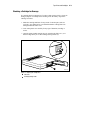
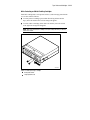
1
TL891 MiniLibrary System User's Guide First Edition (March 1999) Part Number ER-TL891-UA. A01 Compaq Computer Corporation Compaq Confidential – Need to Know Required Writer: Everett Godaire Project: TL891 MiniLibrary System User's Guide Comments: Part Number: ER-TL891-UA. A01 File Name: a-frnt Last Saved On: 3/3/99 12:17 PM Notice The information in this publication is subject to change without notice. COMPAQ COMPUTER CORPORATION SHALL NOT BE LIABLE FOR TECHNICAL OR EDITORIAL ERRORS OR OMISSIONS CONTAINED HEREIN, NOR FOR INCIDENTAL OR CONSEQUENTIAL DAMAGES RESULTING FROM THE FURNISHING, PERFORMANCE, OR USE OF THIS MATERIAL. THIS INFORMATION IS PROVIDED “AS IS” AND COMPAQ COMPUTER CORPORATION DISCLAIMS ANY WARRANTIES, EXPRESS, IMPLIED OR STATUTORY AND EXPRESSLY DISCLAIMS THE IMPLIED WARRANTIES OF MERCHANTABILITY, FITNESS FOR PARTICULAR PURPOSE, GOOD TITLE AND AGAINST INFRINGEMENT. This publication contains information protected by copyright. No part of this publication may be photocopied or reproduced in any form without prior written consent from Compaq Computer Corporation. © 1999 Compaq Computer Corporation. All rights reserved. Printed in the U.S.A. The software described in this guide is furnished under a license agreement or nondisclosure agreement. The software may be used or copied only in accordance with the terms of the agreement. Compaq, Deskpro, Fastart, Compaq Insight Manager, Systempro, Systempro/LT, ProLiant, ROMPaq, QVision, SmartStart, NetFlex, QuickFind, PaqFax, ProSignia, registered United States Patent and Trademark Office. Neoserver, Netelligent, Systempro/XL, SoftPaq, QuickBlank, QuickLock are trademarks and/or service marks of Compaq Computer Corporation. Microsoft, MS-DOS, Windows, and Windows NT are registered trademarks of Microsoft Corporation. Pentium is a registered trademark and Xeon is a trademark of Intel Corporation. Other product names mentioned herein may be trademarks and/or registered trademarks of their respective companies. TL891 MiniLibrary System User's Guide First Edition (March 1999) Part Number ER-TL891-UA. A01 Compaq Confidential – Need to Know Required Writer: Everett Godaire Project: TL891 MiniLibrary System User's Guide Comments: Part Number: ER-TL891-UA. A01 File Name: a-frnt Last Saved On: 3/3/99 12:17 PM Contents About This Guide Text Conventions ................................................................................................. vii Symbols in Text .................................................................................................. viii Symbols on Equipment ........................................................................................ viii Rack Stability........................................................................................................ ix Getting Help.......................................................................................................... ix Compaq Technical Support ............................................................................. ix Compaq Website ............................................................................................. x Compaq Authorized Reseller ........................................................................... x Chapter 1 Introduction Modules ....................................................................................................... 1-1 The Expansion Unit ...................................................................................... 1-3 The Base Module.......................................................................................... 1-3 SCSI Interface Configurations....................................................................... 1-4 SCSI Bus Performance Considerations.......................................................... 1-4 Physical Configuration.................................................................................. 1-5 System Expansion......................................................................................... 1-5 Features........................................................................................................ 1-6 Advanced Design Features.......................................................................... 1-12 Chapter 2 Operation Expansion Unit ............................................................................................. 2-1 Starting the System ....................................................................................... 2-8 The MiniLibrary Menu Structure ................................................................ 2-12 Inserting and Removing Cartridges ............................................................. 2-24 Inserting a Magazine................................................................................... 2-28 Base Module............................................................................................... 2-29 Compaq Confidential – Need to Know Required Writer: Everett Godaire Project: TL891 MiniLibrary System User's Guide Comments: Part Number: ER-TL891-UA. A01 File Name: a-frnt Last Saved On: 3/3/99 12:17 PM iv TL891 MiniLibrary System User's Guide Chapter 3 Installation Introduction.................................................................................................. 3-1 Planning Your Installation ............................................................................ 3-3 Mechanical Installation................................................................................. 3-4 Chapter 4 Configuration How to Customize Configuration.................................................................. 4-1 Descriptions of Configuration Options .......................................................... 4-3 Chapter 5 Regular Maintenance Cleaning Cartridge........................................................................................ 5-2 Chapter 6 Diagnostics and Troubleshooting Diagnosing Problems.................................................................................... 6-1 Error Recovery ............................................................................................. 6-2 Fault Symptom Codes (FSC) ........................................................................ 6-5 Using CE Diagnostics................................................................................. 6-25 Using the Demo Submenu .......................................................................... 6-26 Appendix A Specifications Safety.......................................................................................................... A-5 Electromagnetic Emission............................................................................ A-6 Statement for Equipment Meeting FCC Class A Requirements ..................... A-8 Equipment Meeting VDE Class B Requirements .......................................... A-9 (VFG 1046/84 and VFG 243/91 for Germany) ............................................. A-9 VCCI Notice for Japan Class I Equipment.................................................. A-10 Appendix B Accessories Data and Cleaning Cartridge Ordering Information ...................................... B-1 Bar Code Label and Magazine Ordering Information.................................... B-2 Appendix C Product Notes for Windows NT and Novell NetWare Host SCSI Interface ..................................................................................... C-1 Compaq Confidential – Need to Know Required Writer: Everett Godaire Project: TL891 MiniLibrary System User's Guide Comments: Part Number: ER-TL891-UA. A01 File Name: a-frnt Last Saved On: 3/3/99 12:17 PM Contents v Appendix D Product Notes for Sun General Information..................................................................................... D-1 Modifications Required for Solaris 2.4 (or later)........................................... D-3 Appendix E Product Notes for IBM RS/6000 Modifications Required to Operate the TZ89 DLT Cartridge SBB Tape Drive or Tabletop Drive with AIX 4.1.4 (or later)..........................................E-1 Appendix F Adding a Second Tape Drive Parts Location .....................................................................................................F-1 Overall Procedure................................................................................................F-2 Removing and Replacing the Skin Cover (Desktop Models Only)..................F-2 Removing and Replacing the Cover Plate......................................................F-4 Removing and Replacing the Drive Caddy Assembly ....................................F-5 Installing the Second Tape Drive...................................................................F-7 Appendix G Information on Pass-Through Section Covers Pass-Through Section Covers ............................................................................. G-1 Appendix H Tape Drives and Cartridges Care and Handling of Cartridges .................................................................. H-1 Checking a Cartridge for Damage ................................................................ H-3 Archival Guidelines............................................................................................ H-6 Transportation Guidelines ............................................................................ H-6 Cleaning Guidelines..................................................................................... H-7 Cleaning the Tape Drive Heads.................................................................... H-9 Preparing Cartridges for Use ...................................................................... H-10 Index Compaq Confidential – Need to Know Required Writer: Everett Godaire Project: TL891 MiniLibrary System User's Guide Comments: Part Number: ER-TL891-UA. A01 File Name: a-frnt Last Saved On: 3/3/99 12:17 PM vi TL891 MiniLibrary System User's Guide Compaq Confidential – Need to Know Required Writer: Everett Godaire Project: TL891 MiniLibrary System User's Guide Comments: Part Number: ER-TL891-UA. A01 File Name: a-frnt Last Saved On: 3/3/99 12:17 PM About This Guide This guide is designed to be used as step-by-step instructions for installation and as a reference for operation, troubleshooting, and future upgrades. Text Conventions This document uses the following conventions to distinguish elements of text: Keys Keys appear in boldface. A plus sign (+) between two keys indicates that they should be pressed simultaneously. USER INPUT User input appears in a different typeface and in uppercase. FILENAMES File names appear in uppercase italics. Menu Options, Command Names, Dialog Box Names These elements appear in initial capital letters. COMMANDS, DIRECTORY NAMES, and DRIVE NAMES These elements appear in uppercase. Type When you are instructed to type information, type the information without pressing the Enter key. Enter When you are instructed to enter information, type the information and then press the Enter key. Compaq Confidential – Need to Know Required Writer: Everett Godaire Project: TL891 MiniLibrary System User's Guide Comments: Part Number: ER-TL891-UA. A01 File Name: a-frnt Last Saved On: 3/3/99 12:17 PM viii TL891 MiniLibrary System User's Guide Symbols in Text These symbols may be found in the text of this guide. They have the following meanings. WARNING: Text set off in this manner indicates that failure to follow directions in the warning could result in bodily harm or loss of life. CAUTION: Text set off in this manner indicates that failure to follow directions could result in damage to equipment or loss of information. IMPORTANT: Text set off in this manner presents clarifying information or specific instructions. NOTE: Text set off in this manner presents commentary, sidelights, or interesting points of information. Symbols on Equipment These icons may be located on equipment in areas where hazardous conditions may exist. Any surface or area of the equipment marked with these symbols indicates the presence of electrical shock hazards. Enclosed area contains no operator serviceable parts. WARNING: To reduce the risk of injury from electrical shock hazards, do not open this enclosure. Any RJ-45 receptacle marked with these symbols indicates a Network Interface Connection. WARNING: To reduce the risk of electrical shock, fire, or damage to the equipment, do not plug telephone or telecommunications connectors into this receptacle. Compaq Confidential – Need to Know Required Writer: Everett Godaire Project: TL891 MiniLibrary System User's Guide Comments: Part Number: ER-TL891-UA. A01 File Name: a-frnt Last Saved On: 3/3/99 12:17 PM Contents ix Any surface or area of the equipment marked with these symbols indicates the presence of a hot surface or hot component. If this surface is contacted, the potential for injury exists. WARNING: To reduce the risk of injury from a hot component, allow the surface to cool before touching. Power Supplies or Systems marked with these symbols indicate the equipment is supplied by multiple sources of power. WARNING: To reduce the risk of injury from electrical shock, remove all power cords to completely disconnect power from the system. Rack Stability WARNING: To reduce the risk of personal injury or damage to the equipment, be sure that: ■ The leveling jacks are extended to the floor. ■ The full weight of the rack rests on the leveling jacks. ■ The stabilizing feet are attached to the rack if it is a single rack installations. ■ The racks are coupled together in multiple rack installations. ■ A rack may become unstable if more than one component is extended for any reason. Extend only one component at a time. Getting Help If you have a problem and have exhausted the information in this guide, you can get further information and other help in the following locations. Compaq Technical Support You are entitled to free hardware technical telephone support for your product for as long you own the product. A technical support specialist will help you diagnose the problem or guide you to the next step in the warranty process. Compaq Confidential – Need to Know Required Writer: Everett Godaire Project: TL891 MiniLibrary System User's Guide Comments: Part Number: ER-TL891-UA. A01 File Name: a-frnt Last Saved On: 3/3/99 12:17 PM x TL891 MiniLibrary System User's Guide In North America, call the Compaq Technical Phone Support Center at 1 1-800-OK-COMPAQ . This service is available 24 hours a day, 7 days a week. Outside North America, call the nearest Compaq Technical Support Phone Center. Telephone numbers for world wide Technical Support Centers are listed on the Compaq website. Access the Compaq website by logging on to the Internet at http://www.compaq.com. Be sure to have the following information available before you call Compaq: ■ Technical support registration number (if applicable) ■ Product serial number (s) ■ Product model name(s) and numbers(s) ■ Applicable error messages ■ Add-on boards or hardware ■ Third-party hardware or software ■ Operating system type and revision level ■ Detailed, specific questions Compaq Website The Compaq website has information on this product as well as the latest drivers and Flash ROM images. You can access the Compaq website by logging on to the Internet at http://www.compaq.com. Compaq Authorized Reseller For the name of your nearest Compaq Authorized Reseller: 1 ■ In the United States, call 1-800-345-1518. ■ In Canada, call 1-800-263-5868. ■ Elsewhere, see the Compaq website for locations and telephone numbers. For continuous quality improvement, calls may be recorded or monitored. Compaq Confidential – Need to Know Required Writer: Everett Godaire Project: TL891 MiniLibrary System User's Guide Comments: Part Number: ER-TL891-UA. A01 File Name: a-frnt Last Saved On: 3/3/99 12:17 PM Chapter 1 Introduction This chapter describes the features of the expansion and base modules of the MiniLibrary System, including Storage Architecture, SCSI Interface, Bus Performance, and Physical Configuration/Expansion Options. The MiniLibrary System is an expandable, modular tape library system combining DLT technology drive with advanced robotics. The MiniLibrary System is designed for high duty-cycle on-line and near-on-line applications, such as hierarchical storage management (HSM). It is a superior performer in high-volume backup and archival service as well. Modules Two types of modules comprise the MiniLibrary System: ■ Expansion Unit (Master) ■ MiniLibrary (Base Module) The MiniLibrary System consists of one Expansion Unit and up to five MiniLibrary base modules stacked in a rack. The Expansion Unit can move media freely between itself and Base Modules via the system’s roboticallycontrolled pass-through mechanism. In a MiniLibrary System, you can combine modules to provide the right combination of capacity and performance to meet your present storage requirements. Compaq’s MiniLibrary storage architecture lets you add modules to optimize throughput and capacity as your needs change. Compaq Confidential – Need to Know Required Writer: Everett Godaire Project: TL891 MiniLibrary System User's Guide Comments: Part Number: ER-TL891-UA.A01 File Name: b-ch1 Introduction Last Saved On: 3/1/99 4:07 PM 1-2 TL891 MiniLibrary System User's Guide MiniLibrary Storage Architecture When connected as a system, the robotics in the MiniLibrary Expansion Unit act as commanded by the host computer(s). The host(s) need no knowledge of the internal geometry of the system, or of the actions or capabilities of the Base Modules. The Expansion Unit presents to the host(s) a single SCSI medium changer device with a single SCSI Medium Transport element, a number of SCSI Storage elements equal to the total number of cartridge magazine slots, a number of SCSI Import/Export elements as specified by the user during configuration of the Expansion Unit, and a number of SCSI Data Transfer elements equal to the total number of drives in the system. Flexibility Compaq’s MiniLibrary storage architecture is uniquely suited to growing storage needs. Its flexible library robotics system enables you to start with a system configured to your present requirements, confident that as your storage needs evolve, you can easily modify the MiniLibrary by adding modules and extending the pass-through mechanism. Add drives for faster performance or magazine space for greater capacity, as needed. Then just turn on the power, and immediately the system updates the system map so the host is informed of the expanded capability. Multi-Server Data Sharing A host computer with a SCSI controller connected to a bus is a SCSI Initiator. The Expansion Unit is a SCSI Target. SCSI rules permit multiple Initiators on a single bus. Therefore, with the proper host software, it is possible to connect multiple hosts to a single Expansion Unit over a single SCSI bus. This allows multiple hosts to operate the library robotics, loading and unloading cartridges as each host requires. In a system with many drives, it is desirable to use multiple SCSI buses for the drives, so the data transfer rate of the drives is not limited by bus bandwidth. In a large, high-performance system, drives may be connected to separate hosts. Using special software, one of the hosts can act as a master server, processing all robotics commands. In this way several hosts may share a common data base. Compaq Confidential – Need to Know Required Writer: Everett Godaire Project: TL891 MiniLibrary System User's Guide Comments: Part Number: ER-TL891-UA.A01 File Name: b-ch1 Introduction Last Saved On: 3/1/99 4:07 PM Introduction 1-3 The Expansion Unit Description The Expansion Unit integrates the robotics in the individual modules into a single coordinated library robotics system. The Expansion Unit performs and maintains an inventory of all media present in the system, including bar code data. All necessary system control operations may be performed from the control panel of the Expansion Unit, as well as from the host via software. The SCSI interface for the library robotics is designed for high-speed communication with the host, and Fast/Wide SCSI configurations. In addition to its system control functions, the Expansion Unit has a 16cartridge magazine with a rugged random access robotic mechanism. The module robotics moves cartridges between the pass-through mechanism and any of the 16 cartridge storage locations. The user may designate a magazine in one of the base modules as a mail slot for inserting or removing one or more single cartridges, which implements the SCSI Import/Export commands. NOTE: A magazine that has been reserved for Import/Export service may not be used for data storage. The Base Module Description The Base Module has one or two TZ89 tape drives and a 10-cartridge magazine with a rugged random access robotic mechanism. Models The TL891 using one or two TZ89 series drives, also use the DLTtape IV cartridges, which provide a native capacity of 35 GB per cartridge. All models can also read and write DLTTape III and DLTtape IIIxt cartridges. Both read and write densities are selectable from the front panel, and under SCSI control from the host. Compaq Confidential – Need to Know Required Writer: Everett Godaire Project: TL891 MiniLibrary System User's Guide Comments: Part Number: ER-TL891-UA.A01 File Name: b-ch1 Introduction Last Saved On: 3/1/99 4:07 PM 1-4 TL891 MiniLibrary System User's Guide SCSI Interface Configurations Systems are equipped with TZ89 drives use a Fast/Wide SCSI interface using high-density 68-pin D-series connectors. The section on SCSI Interfaces in Chapter 3, Installation, describes the available interface options. SCSI Bus Performance Considerations Data Transfer Rate The data transfer rate of the MiniLibrary is dependent on the type and number of drives and on the SCSI bus configuration. The bandwidth of the SCSI bus is limited. As a result, the transfer rate of exceptionally fast drives such as the TZ89 can be limited by sharing a SCSI bus with another disc drive on tape. Drives With a standard SCSI interface, modules equipped with TZ89 drives have a native data transfer rate of 5.0 MB/second, 10 MB/sec for two drives. The rates for compressed data are dependent on compression ratio, record size, data type, and other system parameters, but averages approximately 1:7. Internal Cabling Configuration The MiniLibrary System is wired in an independent-bus SCSI configuration. That is, the robotics and each of the drives has its own SCSI bus. SCSI jumpers are available for those applications requiring that some combination of drives and robotics be daisy-chained to a single SCSI bus. These configurations are described in more detail in the section on SCSI Interfaces in Chapter 3, Installation. Compaq Confidential – Need to Know Required Writer: Everett Godaire Project: TL891 MiniLibrary System User's Guide Comments: Part Number: ER-TL891-UA.A01 File Name: b-ch1 Introduction Last Saved On: 3/1/99 4:07 PM Introduction 1-5 Physical Configuration The Expansion Unit must be mounted at the top of the stack, which places its control panel at a convenient height. The control panels of the Base Modules are of secondary importance, as they serve mainly to help localize system failures. When installed, the motor drive assembly of the pass-through mechanism is directly behind the Expansion Unit. Base modules may be installed anywhere below the Expansion Unit, in any order. There may be a slight performance advantage in making the Base Modules contiguous, but gaps are permitted. The size of a gap is limited by the fact that each gap must be bridged by some number of 7” pass-through mechanism track sections. For safety, available cover plates should be installed on all pass-through mechanism sections that are not connected to MiniLibrary modules. The Expansion Unit senses the position of each module during initialization at power-up. Even if there are gaps between modules, the system will operate correctly. If you plan to leave gaps between modules, be sure to order additional pass-through mechanism track segments and cover plates equal to the length of the gap. System Expansion A MiniLibrary System may be expanded in capacity and performance by adding or removing TL891 modules. Associated with the Expansion Unit and each of the Base Module(s) is a section of the pass-through mechanism. System firmware integrates all of the robotics of these system modules with that of the pass-through mechanism into a single high-performance library robotics system. Compaq Confidential – Need to Know Required Writer: Everett Godaire Project: TL891 MiniLibrary System User's Guide Comments: Part Number: ER-TL891-UA.A01 File Name: b-ch1 Introduction Last Saved On: 3/1/99 4:07 PM 1-6 TL891 MiniLibrary System User's Guide Features Figures 1-1 through 1-5 identify some of the external features of the Expansion Unit and the MiniLibrary. 1 2 3 4 5 Figure 1-1. Expansion Unit Front View 16-Cartridge Magazine 1 2 3 Magazine Security Lock Control Panel 4 5 6 6 SHR-1194 Unlock/Open Button Locked Indicator Power Switch Compaq Confidential – Need to Know Required Writer: Everett Godaire Project: TL891 MiniLibrary System User's Guide Comments: Part Number: ER-TL891-UA.A01 File Name: b-ch1 Introduction Last Saved On: 3/1/99 4:07 PM Introduction 1-7 1 2 3 Use Cleane r 4 Drive Fault Loader Fault 5 6 Figure 1-2. Base Module Front View 10-Cartridge Magazine 1 2 3 Magazine Security Lock Control Panel 4 5 6 SHR-1195 Unlock/Open Button Locked Indicator Power Switch Control Panel The control panels for all modules are the same, except for the number of LED indicators. The control panel features a 4-line by 20-character backlit LCD display, three or four LED indicators, and four buttons. The buttons enable the operator to navigate through the menu structure to select and display operating modes, device status, diagnostic and maintenance functions, device history and error statistics, and system configuration. The functions of the control panel are described in detail in Chapter 2, Operation. Display The backlit 4-line by 20-character control panel display provides a highly intelligible presentation of drive and loader status, menu choices and error messages. The scrolling feature greatly expands the amount of information available to the operator. In the Expansion Unit, status information is available for the entire system. The base modules display other information as needed for localizing malfunctions. Compaq Confidential – Need to Know Required Writer: Everett Godaire Project: TL891 MiniLibrary System User's Guide Comments: Part Number: ER-TL891-UA.A01 File Name: b-ch1 Introduction Last Saved On: 3/1/99 4:07 PM 1-8 TL891 MiniLibrary System User's Guide Magazine Security Lock The Magazine Security Lock is a key-operated switch on the front panel of each module. It can be used to prevent inadvertent removal of the cartridge magazine. Power Supply The AC Power switch is located on the front panel of the module. The autoranging power supply will adjust automatically to either of two operating voltage ranges. The ranges are 100-120 VAC and 200-240 VAC. The power supply is capable of operating at 50 or 60 Hz without any adjustment or modification. AC power is supplied to the power supply by a single IECcompatible socket that can be connected to any properly grounded outlet. Tape Cartridge Magazines The 10-cartridge and 16-cartridge magazines are removable from the front panel, but may be protected from tampering by any of three means: 1) a keyoperated Magazine Security Lock which must be unlocked before the magazine can be removed, 2) an electronic combination lock operated by using buttons on the Expansion Unit control panel, and 3) issuance by the host of a SCSI ‘Prevent Medium Removal’ command. The rugged carbon-fiberreinforced polymer magazine fits into an extruded track, which assures precise positioning with respect to the library robotics. A 10-cartridge tape magazine is shown in Figure 1-3. Insertion and removal of the magazine is described in Chapter 2, Operation. Compaq Confidential – Need to Know Required Writer: Everett Godaire Project: TL891 MiniLibrary System User's Guide Comments: Part Number: ER-TL891-UA.A01 File Name: b-ch1 Introduction Last Saved On: 3/1/99 4:07 PM Introduction 1-9 1 4 3 2 SHR-1226 Figure 1-3. Base Module 10-Cartridge Magazine Slot 0 Barcode Label Slide Slot (not used) 1 2 Front Label Slide Slot 3 4 Slot 9 Compaq Confidential – Need to Know Required Writer: Everett Godaire Project: TL891 MiniLibrary System User's Guide Comments: Part Number: ER-TL891-UA.A01 File Name: b-ch1 Introduction Last Saved On: 3/1/99 4:07 PM 1-10 TL891 MiniLibrary System User's Guide 1 5 4 3 2 SHR-1227 Figure 1-4. Expansion Unit Rear View Pass-Through Mechanism Motor Drive 1 2 3 Power Connector 4 Library Robotics SCSI Interface 5 Diagnostics Connector Base Module Robotics Interface Connectors Compaq Confidential – Need to Know Required Writer: Everett Godaire Project: TL891 MiniLibrary System User's Guide Comments: Part Number: ER-TL891-UA.A01 File Name: b-ch1 Introduction Last Saved On: 3/1/99 4:07 PM Introduction 1-11 1 4 3 2 SHR-1228 Figure 1-5. Base Module Rear View SCSI Interface 1 2 Expansion Unit Interface 3 4 Power Connector Fan Integral Fan Cooling A single forced-air fan is mounted inside each module to provide optimum cooling for critical parts, and to prevent the drive and robotics electronics, motors and power supply from overheating. Library Robotics The MiniLibrary System features library robotics that can load any of the cartridges stored in any magazine in the system into any of the tape drives, moving cartridges among as many as five modules within the MiniLibrary System. Bar Code Reader The bar code reader is mounted on the cartridge shuttle in each module. It reads bar code labels attached to each cartridge, and maintains the bar code data in memory as part of the library System Map. Compaq Confidential – Need to Know Required Writer: Everett Godaire Project: TL891 MiniLibrary System User's Guide Comments: Part Number: ER-TL891-UA.A01 File Name: b-ch1 Introduction Last Saved On: 3/1/99 4:07 PM 1-12 TL891 MiniLibrary System User's Guide Advanced Design Features The MiniLibrary System incorporates many significant improvements in tape drive and library design. One of the most important is the use of highly reliable DLT technology, with media rated by the media manufacturer at better than 1,000,000 head passes. Embedded Diagnostics The MiniLibrary System and each of its modules provide three levels of embedded diagnostics. The Power-On Self Test (POST) performs various verification tests on the system’s configuration and host interface and device control functions, as well as memory tests, at power-up. The second level of diagnostics is the User Diagnostics, which provide for displaying and changing configuration options. The third level, Customer Engineer (CE) Diagnostics, include advanced diagnostics to be used by Customer Engineers for servicing the MiniLibrary System. Both the User Diagnostics and the CE Diagnostics may be selected from the front panel. User Diagnostics are described in greater detail in Chapter 3, Installation. Error Checking Drives used in the MiniLibrary System apply a 16-bit parity check to each record, a 64-bit CRC to each 4 kb of data, and Reed-Solomon error correction code overall. In addition, there is an internal parity check on the data buffer. Compression MiniLibrary System drives use the standard Digital Lempel-Ziv (DLZ) data compression algorithm. Capacity A Base Module with its 10-cartridge magazine and a single Expansion unit with its 16-cartridge magazine offers the formatted capacities shown in Table 1-1. Compaq Confidential – Need to Know Required Writer: Everett Godaire Project: TL891 MiniLibrary System User's Guide Comments: Part Number: ER-TL891-UA.A01 File Name: b-ch1 Introduction Last Saved On: 3/1/99 4:07 PM Introduction 1-13 Table 1-1 MiniLibrary System Tape Capacity MODEL CARTRIDGE MAGAZINE CAPACITY FULL MAGAZINE UNCOMPRESSED FULL MAGAZINE COMPRESSED @ 2:1 TL891 DLTtape IV 10 350 GB 700 GB TL890 DLTtape IV 16 560 GB 1120 GB Media Life The media used in the MiniLibrary is rated by the media manufacturer at over 1,000,000 head passes, and a shelf life of at least 30 years. Compaq Confidential – Need to Know Required Writer: Everett Godaire Project: TL891 MiniLibrary System User's Guide Comments: Part Number: ER-TL891-UA.A01 File Name: b-ch1 Introduction Last Saved On: 3/1/99 4:07 PM Chapter 2 Operation This chapter describes manual operation of the MiniLibrary System through the Expansion Unit (Master) control panel, (the normal manner of manual operation), and the online and offline operations which may be performed through the MiniLibrary (base) control panel. Expansion Unit Front Panel The front panel of the Expansion Unit (reference Figure 2-1) includes a power switch for the unit, and the control panel that has buttons, a display, and LED indicators. Compaq Confidential – Need to Know Required Writer: Everett Godaire Project: TL891 MiniLibrary System User's Guide Comments: Part Number: ER-TL891-UA.A01 File Name: c-ch2 Operation Last Saved On: 3/1/99 2:14 PM 2-2 TL891 MiniLibrary System User's Guide 1 2 3 4 5 Figure 2-1. Expansion Unit Front Panel 16-Cartridge Magazine 1 2 3 Magazine Security Lock Control Panel 4 5 6 6 SHR-1194 Unlock/Open Button Locked Indicator Power Switch Compaq Confidential – Need to Know Required Writer: Everett Godaire Project: TL891 MiniLibrary System User's Guide Comments: Part Number: ER-TL891-UA.A01 File Name: c-ch2 Operation Last Saved On: 3/1/99 2:14 PM Operation 2-3 Power Switch The power switch controls the supply of AC power to the module. It is set into a recess in the front panel to prevent accidental operation. Press 1 to turn the module ON and 0 to turn the module OFF. NOTE: The Expansion Unit must be turned on after or simultaneously with the Base Module(s). If this is not done, the Expansion Unit may not be notified of the presence of one or more of the Base Modules. Control Panels The Expansion Unit control panel, shown in Figure 2-2, consists of three LED indicators, a four-line by 20-character backlit LCD display, and four buttons. The Base Module control panel, shown in Figure 2-3, has four LED indicators, Expansion Unit Indicators There are three LED indicators on the Expansion Unit control panel, labeled Ready (green), Alert (yellow), and Fault (red), that serve as follows: ■ Ready (green) - illuminates when the system is ready to accept commands, either from the control panel or from the host computer. The Ready indicator goes out when you enter the Menu Mode. ■ Alert (yellow) - indicates that a fault or some other matter that requires attention has occurred in one of the modules in the system. Line 2 of the display blinks the number of the module where the fault has occurred. The control panels of the indicated module may give a further indication of the cause of the alert. Often, when the Alert LED is lit, a Fault LED is illuminated on one or more of the Base Modules as well. ■ Fault (red) - indicates that a fault has occurred in the Expansion Unit, or that the magazine door is unable to close. When the red LED is illuminated, a Fault Screen appears on the LCD display. The Fault Screen is described later in this chapter. A list of fault symptom codes (FSC) and error recovery procedures (ERP) appears in Chapter 6, Diagnostics and Troubleshooting. Compaq Confidential – Need to Know Required Writer: Everett Godaire Project: TL891 MiniLibrary System User's Guide Comments: Part Number: ER-TL891-UA.A01 File Name: c-ch2 Operation Last Saved On: 3/1/99 2:14 PM 2-4 TL891 MiniLibrary System User's Guide Read y Alert Fault Esca pe Ente r SHR-1229 Figure 2-2. Expansion Unit Control Panel Compaq Confidential – Need to Know Required Writer: Everett Godaire Project: TL891 MiniLibrary System User's Guide Comments: Part Number: ER-TL891-UA.A01 File Name: c-ch2 Operation Last Saved On: 3/1/99 2:14 PM Operation 2-5 Base Module Indicators There are four LED indicators on the Base Module control panel, labeled Ready (green), Use Cleaner (yellow), Drive Fault (red), and Loader Fault (red), that serve as follows: ■ Ready (green) - illuminates when the Base Module is ready to accept commands, either from the control panel or from the host computer via the Expansion Unit. The Ready indicator goes out when you enter the Menu Mode. ■ Use Cleaner (yellow) - indicates that either or both drives require cleaning. A cleaning operation should be performed as described in Chapter 5, Regular Maintenance. When the Use Cleaner LED comes on, you can find out which drive needs cleaning by selecting Cleaning Needed on the Drive Status submenu. ■ Drive or Loader Fault (red) - illuminates when a Fault Screen appears on the LCD display. The Fault Screen is described later in this chapter. A list of fault symptom codes (FSC) and error recovery procedures (ERP) appears in Chapter 5, Regular Maintenance. Read y Esca pe Use Clea ner Drive Fault Load er Fault Ente r SHR-1248 Figure 2-3. MiniLibrary Base Module Control Panel Buttons - All Modules There are four buttons on the control panel, labeled Escape, Enter, , and The buttons do not directly control specific functions or options. Instead, you use the buttons to navigate from the Default Screen through a multi-level menu structure, then select the desired option from the appropriate menu using Compaq Confidential – Need to Know Required Writer: Everett Godaire Project: TL891 MiniLibrary System User's Guide Comments: Part Number: ER-TL891-UA.A01 File Name: c-ch2 Operation Last Saved On: 3/1/99 2:14 PM 2-6 TL891 MiniLibrary System User's Guide the Enter button. Table 2-1 describes the effect of each of the four buttons under various conditions. The three most important things you need to know about the buttons are: 1. To enter the Menu Mode and display the Main Menu from the Default Screen, press the Enter button. 2. To return to the Main Menu from a submenu, press the Escape button repeatedly until the Main Menu appears. Pressing the Escape button while the Main Menu is displayed exits the Menu Mode and returns you to the Default Screen. The Default Screen is shown in Figure 2-6; the Main Menu is shown in Figure 2-10. 3. To display the Show Status Menu only without entering the Menu Mode, press the Escape button at the Default Screen. The system remains online. NOTE: When you enter the Menu Mode at the Expansion Unit, the Ready light on that module goes out. This means that the MiniLibrary system is off-line, and the system responds to all commands from the host with a SCSI ‘Not Ready’ until you exit the Menu Mode and the Ready light goes on. When you enter the Menu Mode at any of the Base Modules, the Ready light on that module goes out. This means that the individual module is off-line, and the system responds to all commands from the host pertaining to that module with a SCSI ‘Not Ready’ until you exit the Menu Mode and the Ready light goes on. Compaq Confidential – Need to Know Required Writer: Everett Godaire Project: TL891 MiniLibrary System User's Guide Comments: Part Number: ER-TL891-UA.A01 File Name: c-ch2 Operation Last Saved On: 3/1/99 2:14 PM Operation 2-7 Table 2-1 Control Panel Button Functions Escape Enter At POST Screen N/A N/A N/A N/A At Default Screen Displays Status Menu Enters menu mode N/A N/A At Status Submenu Returns to Default Screen Same as in Menu Mode Same as in Menu Mode Same as in Menu Mode In Menu Mode Rejects currently displayed choice, or Accepts currently displayed choice 1 line Moves upward through list of options, or 1 line Moves downward through list of options, or SCROLLS PART OF DISPLAY 1 LINE TOWARD TOP OF LIST OF OPTIONS Scrolls Part Of Display 1 Line Toward Bottom Of List Of Options N/A N/A ABORTS CONTROL PANEL OPERATION IN PROGRESS, OR EXITS TO NEXT HIGHER MENU LEVEL, OR EXITS MENU MODE TO DEFAULT SCREEN At Fault Screen N/A NOTE: There is an auto-repeat feature for the and buttons. When the user presses either button for more than one-half second, the control panel behaves as if the user were pressing and releasing the button about four times per second. This effect stops when the user releases the button. Compaq Confidential – Need to Know Required Writer: Everett Godaire Project: TL891 MiniLibrary System User's Guide Comments: Part Number: ER-TL891-UA.A01 File Name: c-ch2 Operation Last Saved On: 3/1/99 2:14 PM 2-8 TL891 MiniLibrary System User's Guide Front Panel and Media Locks To avoid accidental interruption of system operation by entering the Menu Mode or removing cartridges while the host is accessing the system, the front panel and the media for each module may be electronically locked. When the front panel of the Expansion Unit is locked, you can only enter the Menu Mode after entering a 4-digit code. That is, when the Default Screen is displayed, pressing the Enter button does not invoke the Menu Mode until you enter the code. The front panel of a Base Module cannot be unlocked without using the Security submenu on the Expansion Unit to unlock it. All Base Module front panels are locked by default when connected to a Expansion Unit. Media located in any or all modules may be locked and unlocked using the Security submenu on the Expansion Unit. When the media are locked, you can only remove media after unlocking the module from the Expansion Unit using the Security submenu. Procedures for locking and unlocking front panels and media are described later in this chapter. Starting the System NOTE: When turning on power to the MiniLibrary, power must be applied to the Expansion Unit either simultaneously with or after the other modules. If the Expansion Unit is powered on first, its inventory of modules may be incorrect, and the contents of some or all of the modules will be inaccessible to the system and to the host. Display Messages The display on the control panel is capable of displaying four lines of 20 characters each, to allow the use of easy-to-understand messages. Many of these messages and their functions are described in this chapter. Those displays that are described in other chapters are cross-referenced here as well. Compaq Confidential – Need to Know Required Writer: Everett Godaire Project: TL891 MiniLibrary System User's Guide Comments: Part Number: ER-TL891-UA.A01 File Name: c-ch2 Operation Last Saved On: 3/1/99 2:14 PM Operation 2-9 Power-On Self Test Screen When power is first applied to the module, a series of power-on self test (POST) diagnostics are performed. During POST execution, the model number of the module, the firmware revision, the status or result of the test in progress and the current date and time are displayed on the control panel as shown in Figure 2-4: COMPAQ TL89x Firmware Level 0X.xx Checking Hardware 26-Feb-19xx 15:35:59 Figure 2-4. POST Screen Initialization Screens After the POST is completed, the library robotics system is initialized. A series of screens similar to similar to Figure 2-5 is displayed during this process: COMPAQ TL89x Firmware Level 0X.xx Initializing Loader 26-Feb-19xx 15:35:59 Figure 2-5. Initialization Screen Default Screen After the POST diagnostics have concluded successfully and initialization is complete, the system Default Screen shown in Figure 2-6 appears: READY Modules:0_ _ _ _ _ _ 0 ________ 9 10 _ _ _ _ 15 Figure 2-6. Default Screen The numbers on the second line correspond to the Base Modules that are connected to the system. Up to five Base Modules may be connected. The third and fourth lines represent the cartridge magazine in the Expansion Unit. A rectangle will appear in each position that contains a cartridge. An underline represents an empty slot. Compaq Confidential – Need to Know Required Writer: Everett Godaire Project: TL891 MiniLibrary System User's Guide Comments: Part Number: ER-TL891-UA.A01 File Name: c-ch2 Operation Last Saved On: 3/1/99 2:14 PM 2-10 TL891 MiniLibrary System User's Guide Fault Screen When a fault is detected within the Expansion Unit or the pass-through mechanism, a screen similar to Figure 2-7 appears. When a fault is detected in one of the base modules, the Alert LED on the Expansion Unit control panel is illuminated. The Fault Screen appears on the malfunctioning Base Module. At the same time, either the Drive Fault or the Loader Fault LED is illuminated on that module. Fault Code: XXXX Error Description ERP line 1 ERP line 2 Figure 2-7. Fault Screen The first line in Figure 2-7 shows a numerical fault symptom code (FSC). The second line shows a brief description of the error, in place of the words, ‘Error Description'. The third and fourth lines will contain a one- or two-line message describing the initial error recovery procedure (ERP) in place of the words shown in the Fault Screen. A list of the fault symptom codes (FSC) and error recovery procedures (ERP) appears in Chapter 6, Diagnostics and Troubleshooting. Base Module Default Screen The Base Modules display a different Default Screen, as shown in Figure 2-8: DLT0 Seeking DLT1 Idle Loader Idle 16 _ _ _ _ _ _ _ _ 25 Figure 2-8. Base Module Default Screen The example shown is a Base Module in the module 1 position. The first and second lines of the Default Screen show the status of the two drives within the Base Module. On line 4, a rectangle appears in each position that contains a cartridge. An underline would appear at each empty slot. The numbers at the beginning and end of line 4 represent the numbers the system has assigned to the first and last slots of that module. Compaq Confidential – Need to Know Required Writer: Everett Godaire Project: TL891 MiniLibrary System User's Guide Comments: Part Number: ER-TL891-UA.A01 File Name: c-ch2 Operation Last Saved On: 3/1/99 2:14 PM Operation 2-11 The possible status conditions of the drives are: ■ No Tape ■ Idle ■ Rewinding ■ Seeking ■ Reading ■ Writing ■ Erasing ■ Cleaning ■ Unloaded ■ Loading ■ Unloading ■ Hard Error ■ In Flux ■ Fault The third line in a Base Module tells the status of the library robotics (Loader) within the Base Module. The possible conditions of the library robotics are: ■ Idle ■ Fetch/Stow ■ Taking Inventory ■ Checking Drives ■ Scanning Labels ■ Orphaned Cartridge ■ Trapped Cartridge ■ Elevator Home Compaq Confidential – Need to Know Required Writer: Everett Godaire Project: TL891 MiniLibrary System User's Guide Comments: Part Number: ER-TL891-UA.A01 File Name: c-ch2 Operation Last Saved On: 3/1/99 2:14 PM 2-12 TL891 MiniLibrary System User's Guide The fourth line in a Base Module is the magazine map. Numbers 16-25 in Figure 2-8 represent the map numbers of the cartridge slots. In this case, we have a 10-slot magazine in the first position below the 16-slot Expansion Unit. These numbers vary with the position of the module within the system and magazine size. If no magazine is installed, line 4 says ‘No Magazine'. The boxes present on this line indicate that a cartridge is present in the corresponding slot of the magazine. An underline means that there is no cartridge present in that slot. Selecting Control Panel Display Modes As previously described, the POST, Initialization and Default Screens appear without operator or host intervention. The Fault Screens appear whenever a fault occurs. The screens that follow appear in response to operator actions. The MiniLibrary Menu Structure Figure 2-9, on the next page, shows the structure of the MiniLibrary menus. Compaq Confidential – Need to Know Required Writer: Everett Godaire Project: TL891 MiniLibrary System User's Guide Comments: Part Number: ER-TL891-UA.A01 File Name: c-ch2 Operation Last Saved On: 3/1/99 2:14 PM Operation 2-13 Power-Up Displays Default Displays Fault Displays Panel Lock* Main Menu Load/Unload From/To Show Status Menu Maintenance Menu Library DLT0 DLT1 Map Info. Configuration Menu Show History Menu Set Data Format Menu Clean Drive Diagnostics Menu Cartridge Cycle Friction Test Tach Feedback Scanner Feedback DLT 0 DLT 1 Error History Set SCSI Menu Initial Config. Library Parity Library Bus ID DLT0 Bus ID DLT1 Bus ID Set Library Mode (1) Demo Menu Demo 1 Flash Update Set Unlock Code Config History Set Element Base Menu Transport Addr. Storage Addr. Transfer Addr. Set Date Menu Day Month Year NOVRAM Update Statistics Security Menu Set Identification Menu Vendor Ident. Product Ident. Set Baud Rate Clock Update Set Time Menu Set Serial Number Flash DLT Set Unload Mode Flash from SCSI Set Auto Clean Reboot Module * Controlled by the Security Menu Set Negotiation Set Mail Slot (2) Negotiation Mode Transfer Rate Set Reserved Slots Set Special Config. Flash from Tape Notes: (1) Applies to Base Module (2) Applies to Expansion Unit Hours Minutes Set Default Scaled AT 90% 2 times Figure 2-9. MiniLibrary Menu Structure Compaq Confidential – Need to Know Required Writer: Everett Godaire Project: TL891 MiniLibrary System User's Guide Comments: Part Number: ER-TL891-UA.A01 File Name: c-ch2 Operation Last Saved On: 3/1/99 2:14 PM Mode PG 1F Length Model Number SHR-1196-2 2-14 TL891 MiniLibrary System User's Guide Entering the Menu Mode IMPORTANT: When the Expansion Unit enters the Menu Mode, the Ready light goes out. This means that the module is offline, and responds to all commands from the host with a SCSI ‘Not Ready’ until you exit the Menu Mode and the Ready light goes on. To prevent inadvertent interruption of host operations, you may lock out the Menu Mode using the Security Menu. See the section entitled Security Menu, later in this chapter. When all control panels are locked, you must enter your unlock code in order to display the Main Menu. Note that the Show Status Menu of each module remains accessible. It may be displayed from the module’s Default Screen at any time by pressing the Escape button. When the Default Screen appears on the screen, you can enter the Menu Mode by pressing the Enter button. The Main Menu shown in Figure 2-10 appears: Load/Unload Show Status Menu Maintenance Menu Configure Menu Figure 2-10. Main Menu NOTE: If the control panel has been locked, the screen shown in Figure 2-11 appears instead of figure2-10. You must know the unlock code for the system before you can proceed. Front Panel Locked ENTER to Unlock ESCAPE to Exit Figure 2-11. Panel Locked Screen When you press the Enter button, the screen shown in Figure 2-12 appears: Unlock Code " " Figure 2-12. Code Entry Submenu Using the button and buttons, set the first digit of the unlock code. When you have set it, press the Enter button to move the cursor to the second digit and repeat the process. When you have finished, press the Escape button, then the Enter button to confirm your entry. If the code is correct, the Main Menu is displayed. If the code is incorrect, an error screen appears. Compaq Confidential – Need to Know Required Writer: Everett Godaire Project: TL891 MiniLibrary System User's Guide Comments: Part Number: ER-TL891-UA.A01 File Name: c-ch2 Operation Last Saved On: 3/1/99 2:14 PM Operation 2-15 Exiting the Menu Mode To leave the menu mode and return to the Default Screen, press the Escape button repeatedly. Each time you press the Escape button, the display moves to a higher menu level. When the Main Menu is visible, pressing the Escape button once returns to the Default Screen. At this point, the Ready LED lights. Navigating Through the Menu Structure To select a submenu, move the on the display to the desired line using the and buttons. Then press the Enter button to confirm your choice and display the submenu. The at the end of the fourth line of the Main Menu means that there are one or more additional items that can be reached by scrolling, using the button. The items available on the Main Menu are: ■ Load/Unload ■ Show Status Menu ■ Maintenance Menu ■ Configuration Menu ■ Show History Menu ■ Security Menu Compaq Confidential – Need to Know Required Writer: Everett Godaire Project: TL891 MiniLibrary System User's Guide Comments: Part Number: ER-TL891-UA.A01 File Name: c-ch2 Operation Last Saved On: 3/1/99 2:14 PM 2-16 TL891 MiniLibrary System User's Guide The following paragraphs describe the submenus that correspond to each of the Main Menu selections. Load/Unload Menu The Load/Unload Menu is described later in this chapter, under the section entitled Loading and Unloading Tapes. Show Status Menu When you select Show Status, the menu shown in Figure 2-13 appears: Library DLT0 DLT1 DLT2 Figure 2-13. Show Status Menu The items available on the Show Status Menu are: ■ Library ■ DLT0 ■ DLT1 ■ ... ■ DLTn ■ Map Info Move the up or down with the button to select the item. and buttons, then press the Enter Compaq Confidential – Need to Know Required Writer: Everett Godaire Project: TL891 MiniLibrary System User's Guide Comments: Part Number: ER-TL891-UA.A01 File Name: c-ch2 Operation Last Saved On: 3/1/99 2:14 PM Operation 2-17 Library Status Submenu When you select Library, the menu shown in Figure 2-14 appears: Model Number: COMPAQ TL89x Firmware Revision 0X.xx Figure 2-14. Library Status Submenu This screen is scrollable. The list of Library Status categories available is as follows: ■ Model Number ■ Firmware Revision ■ Date ■ Time ■ Loader Status ■ Library Configuration ■ Vendor Identification ■ Product Identification ■ Transport Address ■ Storage Address ■ Transfer Address ■ Imp/Exp Address ■ Serial Number ■ SCSI Bus ID ■ SCSI Bus Parity ■ Negotiation Mode ■ Transfer Rate ■ Unload Mode ■ Mail Slot Emulation ■ Mail Slot Count ■ Mode Page 1F Length ■ Initialize Element Status ■ Boot Version ■ Flash Type Compaq Confidential – Need to Know Required Writer: Everett Godaire Project: TL891 MiniLibrary System User's Guide Comments: Part Number: ER-TL891-UA.A01 File Name: c-ch2 Operation Last Saved On: 3/1/99 2:14 PM 2-18 TL891 MiniLibrary System User's Guide Drive Status Menu When you select either of the drives, the menu shown in Figure 2-15 appears: Tape Motion: Idle Tape Format: No Tape Figure 2-15. Drive Status Menu This screen is scrollable. The list of Drive Status categories available is as follows: Map Information Screen When you select Map Info, the screen shown in Figure 2-16 appears. The location being reported appears on Line 1. The content of the bar code on the label, up to 8 characters, appears on Line 4. DLT0 Occupied Label Valid XXXXXXXX Figure 2-16. Map Info Submenu The list of locations available for display on line 1 is as follows. If you do not designate any mail slots, those lines are omitted from the list. Depending on the report for each location, Line 2 may display either ‘Empty’, or ‘Occupied’, or, if a magazine is absent, ‘Not Installed'. Depending on the report for each location, Line 3 may display either ‘Label Valid’, or ‘Label Not Present'. For each location reported, Line 4 will display the actual bar code on the label, up to 8 characters. Maintenance Menu The Maintenance Menu and the options under it that are intended for operator use are described in Chapter 5, Regular Maintenance. Configure Menu The Configure Menu, how to use it and the options available under it are described in Chapter 3, Installation. Compaq Confidential – Need to Know Required Writer: Everett Godaire Project: TL891 MiniLibrary System User's Guide Comments: Part Number: ER-TL891-UA.A01 File Name: c-ch2 Operation Last Saved On: 3/1/99 2:14 PM Operation 2-19 Show History Menu The Show History Menu enables the operator to review the history of the system. An example of the use of the Show History Menu appears later in this chapter under the heading ‘Displaying Error Logs'. You can retrieve the configuration history, the original configuration, as well as statistics on the number of operations the library robotics and the drives have performed. Security Menu The Security Menu permits the operator to lock the control panel, preventing inadvertent or unauthorized access to the Menu Mode, which takes the system offline. You can display the Show Status Menu without unlocking the panel (and without taking the system offline) by pressing the Escape button at the Default Screen. When you select the Security Menu, the screen shown in Figure 2-17 appears: Unlock All Panels Unlock All Media Lock All Panels Lock All Media Figure 2-17. Security Menu This screen is scrollable. The list of Security functions available is as follows: ■ Unlock All Panels ■ Unlock All Media ■ Lock All Panels ■ Lock All Media ■ Master Locking ■ Module 1 Locking ■ ... ■ Module n Locking ■ Set Unlock Code To change the unlock code, or to enable or disable the panel locking function, scroll downward by pressing the button until the is next to ‘Set Unlock Code'. Press the Enter button. The screen shown in Figure 2-18 appears: Unlock Code *"0000" 0000 Disables Lock Figure 2-18. Code Select Submenu An underline cursor appears underneath the first digit. To set the first digit, press the button or the button until the desired number is displayed. To move the cursor to the second digit, press the Enter button. Repeat the process Compaq Confidential – Need to Know Required Writer: Everett Godaire Project: TL891 MiniLibrary System User's Guide Comments: Part Number: ER-TL891-UA.A01 File Name: c-ch2 Operation Last Saved On: 3/1/99 2:14 PM 2-20 TL891 MiniLibrary System User's Guide for each of the four digits. Be sure to remember the 4-digit number, as you will need it in order to enter the Menu Mode. An unlock code of 0000 disables panel locking. When you have finished entering four digits, press the Escape button, the screen shown in Figure 2-19 appears: Unlock Code *"XXXX" ENTER to Accept ESCAPE to Exit Figure 2-19. Code Accept Submenu Your code is shown in place of XXXX. Press the Enter button if you want to adopt the unlock code that is displayed. Press the Escape button if you do not want to accept it. Press the Escape button again to return to the Main Menu, and again to return to the Default Screen. The next time you attempt to enter Menu Mode, the screen shown in Figure 220 appears. You can still display the Status Menu without using the security code by pressing the Escape button at the Default Screen Front Panel Locked ENTER to Unlock ESCAPE to Exit Figure 2-20. Panel Locked Screen When you press the Enter button, the screen shown in Figure 2-21 appears: Unlock Code " " Figure 2-21. Code Entry Submenu Using the and buttons, set the first digit of the unlock code. Press the Enter button to move the cursor to the second digit and repeat the process. When you have finished, press the Escape button. The screen shown in Figure 2-22 appears: Unlock Code *"XXXX" ENTER to Validate ESCAPE to Exit Figure 2-22. Code Validate Submenu Compaq Confidential – Need to Know Required Writer: Everett Godaire Project: TL891 MiniLibrary System User's Guide Comments: Part Number: ER-TL891-UA.A01 File Name: c-ch2 Operation Last Saved On: 3/1/99 2:14 PM Operation 2-21 Press the Enter button to validate your choice. If the code is correct, the Main Menu is displayed. If the code is incorrect, an error screen appears. If you have forgotten your unlock code, contact your technical support representative for assistance. Displaying Firmware Revision You may display the library robotics firmware revision at any time by pressing the Escape button at the Default Screen to display the Show Status Menu. It appears as one of the items on the Library Status submenu of the Show Status Menu. It is also displayed on line 2 of the POST Screen and the Initialization Screens. Displaying Error Logs To display the error history of the module, you need to use the Show History Menu. Access it as follows: Fault Code: XXXX Error Description DD/MMM/YYYY HH:MM:SS Entry NNNN Of NNNN Figure 2-23. Error History Screen Loading and Unloading Tapes The Load/Unload menus enable you to specify a source and a destination for a cartridge movement. As a result, you use exactly the same procedure to load and unload. To load or unload a tape from the front panel of the module, use the Load/Unload menus as follows: READY Modules 012345_ 0 ________ 9 10 _ _ _ _ _ 16 Figure 2-24. Default Screen Compaq Confidential – Need to Know Required Writer: Everett Godaire Project: TL891 MiniLibrary System User's Guide Comments: Part Number: ER-TL891-UA.A01 File Name: c-ch2 Operation Last Saved On: 3/1/99 2:14 PM 2-22 TL891 MiniLibrary System User's Guide A default screen is shown in Figure 2-24 From the Default Screen, enter the Menu Mode by pressing the Enter button. The Main Menu shown in Figure 225 appears: Load/Unload Show Status Menu Maintenance Menu Configure Menu Figure 2-25. Main Menu The is next to the line that reads ‘Load/Unload'. Press the Enter button to display the first Load/Unload submenu, which is shown in Figure 2-26: From: DLT1 To: *Slot3 Figure 2-26. Load/Unload Initial Screen In Figure 2-26, the is next to line 2 of the display. Line 2 shows the top item in a scrollable list of sources. Note that a has appeared on the right of the bottom line. This indicates that the button may now be used to scroll through the list, and that the top item on the list is displayed. As soon as you press the button, three things happen: The list scrolls down one item (only line 2 scrolls). A appears on the right of line 1 of the display. This indicates that there is one or more items above the item displayed on line 2. The * at the left of line 2 disappears. This is because the * indicates the current selection or the default selection, and you have scrolled the default selection offscreen, and haven’t yet selected an item from the list. NOTE: The contents of the lists on line 2 and line 4 will vary as follows: Initial Screen - ‘From’ Line The list on line 2 in Figure 2-26 (the ‘From’ line) will include every drive and every magazine slot (including mail slots) that has a cartridge in it (you can’t get a cartridge from a slot or drive that is empty). Initial Screen - ‘To’ Line The list on line 4 of Figure 2-26 (the ‘To’ line) will include all of the valid destination choices, that is, drives and slots that are empty (you can’t put a cartridge into a slot or drive which already has one in it). Compaq Confidential – Need to Know Required Writer: Everett Godaire Project: TL891 MiniLibrary System User's Guide Comments: Part Number: ER-TL891-UA.A01 File Name: c-ch2 Operation Last Saved On: 3/1/99 2:14 PM Operation 2-23 Scroll List - ‘To’ Line There is another limitation on the ‘To’ list. If you have selected a drive on the ‘From’ screen, the ‘To’ list can include only slots. If you have selected a slot on the ‘From’ screen, the ‘To’ list can contain only drives. Let us assume that you want to load the cartridge that is in Slot 4 into any available drive. Use the button to scroll line two to Slot 4. The screen shown n Figure 2-27 appears: From: Slot4 To: *DLT0 Figure 2-27. Load/Unload ‘From‘ Entry Screen When you have scrolled to your desired source, press the Enter button to select it. Notice that in Figure 2-28, two changes occur in the display. The * reappears at the beginning of line 2, indicating that you have made a selection. The now moves to line 4, indicating that you may now select a destination. From: *Slot4 To: *DLT0 Figure 2-28. Load/Unload ‘To’ Entry Screen You can now simply press the Enter button to select DLT0 as the destination. Note that there is no at the end of line 4, nor at the end of line 1. There are no additional choices because 1) you have selected a slot as the source, so the destination must be a drive, and 2) DLT1 already has a cartridge in it, so it cannot be a valid destination. Press the Enter button to select DLT0. In response, the Confirmation Screen shown in Figure 2-29 appears: From: Slot4 To:DLT0 ENTER To Execute ESCAPE To Cancel Figure 2-29. Confirmation Screen As the confirmation screen indicates, to execute the load or unload, press the Enter button. If the confirmation screen does not show your intended source and destination, press the Escape button to return to the ‘From’ entry screen. Compaq Confidential – Need to Know Required Writer: Everett Godaire Project: TL891 MiniLibrary System User's Guide Comments: Part Number: ER-TL891-UA.A01 File Name: c-ch2 Operation Last Saved On: 3/1/99 2:14 PM 2-24 TL891 MiniLibrary System User's Guide When you press the Enter button, the screen shown in Figure 2-30 appears. If the source is a drive, the word ‘Unload’ appears in place of the word ‘Load’ on line 4. From: Slot4 To:DLT0 Load In Progress Figure 2-30. Load/Unload ‘In Progress’ Screen When the load or unload operation is finished, the Default Screen reappears. Inserting and Removing Cartridges When inserting cartridges, be sure that the slot you intend to use is not already reserved in the system map for a cartridge in a drive. The best way to avoid conflicts is to unload all drives, either through your host computer software or by using the Load/Unload command on the Main Menu, described in the previous section. The tape magazine must be removed from the module in order to insert or remove cartridges. To insert or remove the magazine, the following conditions must be met. The Magazine Security Lock must be unlocked, using the key supplied with the module. Refer to Figure 2-31. When the Magazine Security Lock is locked, the Unlock/Open button has no effect. If the module is installed in a reasonably secure environment, you may elect to leave the Magazine Security Lock in the unlocked position. Media locking on the Security Menu must be disabled. Refer to Figure 2-17. The host computer must allow medium removal. The host computer can enable or disable the Unlock/Open button using the SCSI Prevent Allow Medium Removal command. When you press the Unlock/Open button, the message ‘Magazine Locked” will be displayed. The Expansion Unit must be ready, and not actually executing a command. IMPORTANT: When you enter the Menu Mode, the Ready light goes out. The magazine cannot be inserted or removed unless the Ready light is on. To remove the magazine when a failure prevents the Ready light from illuminating, refer to the section entitled Emergency Magazine Removal. Compaq Confidential – Need to Know Required Writer: Everett Godaire Project: TL891 MiniLibrary System User's Guide Comments: Part Number: ER-TL891-UA.A01 File Name: c-ch2 Operation Last Saved On: 3/1/99 2:14 PM Operation 2-25 1 2 SHR-1230 Figure 2-31. Magazine In Place Magazine Security Lock 1 2 Unlock/Open Button Compaq Confidential – Need to Know Required Writer: Everett Godaire Project: TL891 MiniLibrary System User's Guide Comments: Part Number: ER-TL891-UA.A01 File Name: c-ch2 Operation Last Saved On: 3/1/99 2:14 PM 2-26 TL891 MiniLibrary System User's Guide Removing a Magazine Load/Unload Show Status Menu Maintenance Menu Configuration Menu Figure 2-32. Main Menu Maintenance Menu Configuration Menu Show History Menu Security Menu Figure 2-33. Main Menu, Scrolled Unlock All Panels Unlock All Media Lock All Panels Lock All Media Figure 2-34. Security Menu Unlock All Media In Progress Figure 2-35. Unlock All Media Screen Emergency Magazine Removal If a fault occurs that prevents removal of the magazine, turn the power off for thirty seconds. Power up while continuously pressing the button. Continue to hold the button until all of the indicators on the control panel light, then go out. Release the button. The magazine may now be removed. If you are unsuccessful in removing the magazine using this procedure, contract your technical support representative for further advice. Compaq Confidential – Need to Know Required Writer: Everett Godaire Project: TL891 MiniLibrary System User's Guide Comments: Part Number: ER-TL891-UA.A01 File Name: c-ch2 Operation Last Saved On: 3/1/99 2:14 PM Operation 2-27 Inserting Cartridges Into the Magazine A full magazine is shown in Figure 2-36. Insert cartridges so that the label end with the write protect switch is outward, with the write protect switch toward the bottom of the magazine. The lowest numbered cartridge slot in the magazine is closest to the handle. 3 1 2 SHR-1231 Figure 2-36. 10-Slot Tape Magazine with Cartridges Installed Label 1 2 3 Slot 0 Write Protect Switch Compaq Confidential – Need to Know Required Writer: Everett Godaire Project: TL891 MiniLibrary System User's Guide Comments: Part Number: ER-TL891-UA.A01 File Name: c-ch2 Operation Last Saved On: 3/1/99 2:14 PM 2-28 TL891 MiniLibrary System User's Guide Inserting a Magazine Load/Unload Show Status Menu Maintenance Menu Configuration Menu Figure 2-37. Main Menu Maintenance Menu Configuration Menu Show History Menu Security Menu Figure 2-38. Main Menu, Scrolled Unlock All Panels Unlock All Media Lock All Panels Lock All Media Figure 2-39. Security Menu Unlock All Media In Progress Figure 2-40. Unlock All Media Screen Lock All Media In Progress Figure 2-41. Lock All Media Screen Compaq Confidential – Need to Know Required Writer: Everett Godaire Project: TL891 MiniLibrary System User's Guide Comments: Part Number: ER-TL891-UA.A01 File Name: c-ch2 Operation Last Saved On: 3/1/99 2:14 PM Operation 2-29 Base Module The front panel of the Base Module is nearly identical to the Expansion Unit. It includes a power switch for the module, the magazine door, the Magazine Security Lock, the Unlock/Open button with its Locked indicator. The control panel, shown in Figure 2-3, has one more LED indicator than the Expansion Unit. Figure 2-42 shows the Base Module front panel. The Magazine Security Lock, the Unlock/Open Button and the Locked Indicator LED These features are described earlier in this chapter in the section entitled Inserting and Removing Cartridges. Compaq Confidential – Need to Know Required Writer: Everett Godaire Project: TL891 MiniLibrary System User's Guide Comments: Part Number: ER-TL891-UA.A01 File Name: c-ch2 Operation Last Saved On: 3/1/99 2:14 PM 2-30 TL891 MiniLibrary System User's Guide 1 2 3 Use Cleane r 4 Drive Fault Loader Fault 5 6 Figure 2-42. Base Module Front Panel 10-Cartridge Magazine 1 2 3 Magazine Security Lock Control Panel 4 5 6 SHR-1195 Unlock/Open Button Locked Indicator Power Switch Tape Requirements The MiniLibrary System uses ECMA-approved and ANSI proposed-standards DLTtape cartridges. The DLTtape cartridge is a four-inch square plastic cartridge. According to the media manufacturer, the cartridge and the medium are designed to withstand 1,000,000 passes, and to have a shelf life of 30 years when properly stored. Compaq Confidential – Need to Know Required Writer: Everett Godaire Project: TL891 MiniLibrary System User's Guide Comments: Part Number: ER-TL891-UA.A01 File Name: c-ch2 Operation Last Saved On: 3/1/99 2:14 PM Operation 2-31 Cartridge Handling and Storage A DLTtape cartridge should be stored vertically until you select it for use. Do not expose a cartridge to moisture or direct sunlight. Maintain a clean, dustfree working and storage environment. If a DLTtape cartridge is dropped: ■ Inspect the cartridge carefully before you insert it into a MiniLibrary magazine or any drive. ■ Shake the cartridge while listening for the sound of a broken part. Any rattling sound makes a cartridge unfit for use. ■ Inspect the case for distortion or cracks. ■ Inspect the leader by opening the cartridge door as shown in Figure 243. The leader should be positioned as shown in view (1), and should protrude at about a five-degree angle from the case. If the leader is out of position, do not use the cartridge; damage to the drive could result. Under certain conditions, DLT Tape may stick to the drive read/write head during operation. Damage to media, failure of commands or batch jobs to execute, with resulting errors or hangs; failure to unload; apparent need to swap out the drive. When tapes are stored in an environment different from that of the drive, ensure that they are acclimatized, by moving them to a location in close proximity to the drive before attempting to use them. Ideally, tapes should be allowed to acclimate for a time equal to the duration of their storage away from the drive, or 24 hours, whichever is less. Reports have verified that sticking will occur almost immediately with older, used tapes which have been stored at 20°C and 75% humidity, when those tapes are used in a TZ87 drive kept at a higher temperature and lower humidity. High tape humidity causes sticking from HYDROLYSIS, a degradation of the tape which can be reversed by storing the tape for a while in a dry environment Test conditions (cool, damp tapes and warm, dry drives) have produced “stiction” at will, but other conditions may also cause it. Remember to acclimatize tapes before use. Long-term storage specifications are more stringent than those for shorter periods. Cartridges intended for longterm archiving shall be stored in room conditions of 23°C +/-5 (73°F +/-9 at 50% +/-10% relative humidity. Compaq Confidential – Need to Know Required Writer: Everett Godaire Project: TL891 MiniLibrary System User's Guide Comments: Part Number: ER-TL891-UA.A01 File Name: c-ch2 Operation Last Saved On: 3/1/99 2:14 PM 2-32 TL891 MiniLibrary System User's Guide 1 2 3 SHR-1232 Figure 2-43. DLT Tape Cartridge Leader 1 2 3 Write Protect OFF Write Protect ON Compaq Confidential – Need to Know Required Writer: Everett Godaire Project: TL891 MiniLibrary System User's Guide Comments: Part Number: ER-TL891-UA.A01 File Name: c-ch2 Operation Last Saved On: 3/1/99 2:14 PM Operation 2-33 Write Protection The write protection switch of a DLT tape cartridge is also shown in Figure 243. To enable data recording, slide the write protect switch to the right so that no orange color is visible through the window in the write protect switch (2). To write protect the DLT tape cartridge, slide the write protect switch to the left until the orange indicator shows through the window on the write protect switch (3). Barcode Labels Barcode labels are included with the TL891 MiniLibrary and Expansion Unit. Additional labels can be ordered (refer to Appendix B). The label slips into the slot adjacent to the write-protect switch on each tape cartridge. The code used may be Code 39, Codebar, 2-of-9, standard 2-of-5, or interleaved 2-of-5, with a length of 8 digits. Minimum element width is 7.5 mm. Compaq Confidential – Need to Know Required Writer: Everett Godaire Project: TL891 MiniLibrary System User's Guide Comments: Part Number: ER-TL891-UA.A01 File Name: c-ch2 Operation Last Saved On: 3/1/99 2:14 PM Chapter 3 Installation This chapter describes the complete MiniLibrary System installation process from planning and parts identification to mechanical installation, cabling, and configuration. Introduction There are three major steps to the installation of a MiniLibrary System: mechanical installation, cabling, and configuration. Mechanical installation consists of: ■ Installing the Pass-Through mechanism (the two-module version is factory assembled) ■ Mechanical Installation of the expansion and base module(s). instructions are provided for all rack types: Compaq Cabinet, EIA/RETMA Standard 19” cabinet, and StorageWorks SW500, SW600, or SW800 Metric cabinet ■ Installing the Pass-Through mechanism in the rack Cabling consists of: ■ Interconnecting the base modules with the Expansion Unit ■ Connecting the Expansion Unit to the Pass-Through mechanism motor ■ Connecting the base module drive SCSI buses to host SCSI interfaces Compaq Confidential – Need to Know Required Writer: Everett Godaire Project: TL891 MiniLibrary System User's Guide Comments: Part Number: ER-TL891-UA.A01 File Name: d-ch3 Installation Last Saved On: 3/2/99 2:30 PM 3-2 TL891 MiniLibrary System User's Guide ■ Connecting the Expansion Unit to a host SCSI interface ■ Terminating the buses properly Configuration consists of: ■ Using the Configure Menu to customize the configuration options to your particular application The remainder of this chapter describes each of these steps. Compaq Confidential – Need to Know Required Writer: Everett Godaire Project: TL891 MiniLibrary System User's Guide Comments: Part Number: ER-TL891-UA.A01 File Name: d-ch3 Installation Last Saved On: 3/2/99 2:30 PM Installation 3-3 Planning Your Installation The MiniLibrary System is intended to be mounted in a Compaq Cabinet, StorageWorks SW500, SW600, SW800 or a standard 19-inch EIA/RETMA equipment rack with a depth of 24 to 30 inches. Each module is shipped with EIA/RETMA slides installed. Additional hardware for mounting in Compaq and SW500, SW600, and SW800 cabinets is included Every Compaq MiniLibrary System includes: ■ One Expansion Unit ■ One Expandable Pass-Through Mechanism ■ One to five Base Modules, each with one or two TZ89 drives The Expansion Unit has 16 slots and no drives, and serves as controller of the MiniLibrary System. The base modules each have 10 slots plus one or two drives. The Expansion Unit and the Base Module(s) each occupy 7 inches of rack space height. The Pass-Through mechanism is composed of a motor drive assembly plus sections of track whose combined length is equal to the combined heights of the Expansion Unit plus the Base Modules. One extension section of track is needed for the installation of each additional MiniLibrary module. Positioning the Modules The Expansion Unit must be mounted at the top of the stack, which places its control panel at a convenient height. The control panels of the Base Modules are of secondary importance, as they serve mainly to help localize system failures. When installed, the motor drive assembly of the Pass-Through mechanism is directly behind the Expansion Unit. Base modules may be installed anywhere below the Expansion Unit, in any order. There may be a slight performance advantage in making the Base Modules contiguous, but gaps are permitted. The size of a gap is limited by the fact that each gap must be bridged by some number of 7” Pass-Through mechanism track sections. For safety, available cover plates should be installed on all Pass-Through mechanism sections which are not connected to MiniLibrary System modules. The Expansion Unit senses the position of each module during initialization at power-up. Even if there are gaps between modules, the system will operate correctly. If you plan to leave gaps between modules, be sure to order additional Pass-Through mechanism track segments and cover plates equal to the length of the gap. Compaq Confidential – Need to Know Required Writer: Everett Godaire Project: TL891 MiniLibrary System User's Guide Comments: Part Number: ER-TL891-UA.A01 File Name: d-ch3 Installation Last Saved On: 3/2/99 2:30 PM 3-4 TL891 MiniLibrary System User's Guide Mechanical Installation Assembly of the Pass-Through mechanism requires experience working with moderately complex mechanisms, and the ability to follow directions carefully. Identifying the Parts of the Pass-Through Mechanism Locate and identify the Pass-Through mechanism internal and external parts. The Pass-Through mechanism is made up of the following external parts, shown in Figure 3-1: 1 5 2 8 5 7 6 4 6 8 4 8 3 6 5 8 4 SHR-1233 Figure 3-1. Pass-Through Mechanism External Parts Motor drive section Support brace 1 2 3 4 Extension sections Pass-Through base with idler pulley Tie bars 5 6 Left and right rack slide extensions 7 Angle brackets 8 L-Shaped Nut Plates Compaq Confidential – Need to Know Required Writer: Everett Godaire Project: TL891 MiniLibrary System User's Guide Comments: Part Number: ER-TL891-UA.A01 File Name: d-ch3 Installation Last Saved On: 3/2/99 2:30 PM Installation 3-5 NOTE: The slide extensions, (6) in Figure 3-1, are not enclosed with the Pass-Through mechanism parts. They are supplied as part of the installation hardware for the slides that come with each of the modules. Follow the instructions in the section entitled Mechanical Installation of the Expansion and Base Modules. After the rack slides and the base modules are in place, and after the Pass-Through mechanism is assembled, you will install the Pass-Through mechanism in the rack by attaching the support braces (5) to the slide extensions (6) using the angle brackets (7) and L-shaped nut plates (8). The internal parts you will need to recognize during assembly are shown in Figure 3-2, Pass-Through Mechanism Car (Front View) and Figure 3-3, Car Rear View Showing Belt Block. Compaq Confidential – Need to Know Required Writer: Everett Godaire Project: TL891 MiniLibrary System User's Guide Comments: Part Number: ER-TL891-UA.A01 File Name: d-ch3 Installation Last Saved On: 3/2/99 2:30 PM 3-6 TL891 MiniLibrary System User's Guide SHR-1234 Figure 3-2. Pass-Through Mechanism Car (Front View) Compaq Confidential – Need to Know Required Writer: Everett Godaire Project: TL891 MiniLibrary System User's Guide Comments: Part Number: ER-TL891-UA.A01 File Name: d-ch3 Installation Last Saved On: 3/2/99 2:30 PM Installation 3-7 Figure 3-3 displays the Car Rear View Showing Belt Block. 1 2 SHR-1235 Figure 3-3. Car Rear View Showing Belt Block Belt Block 1 2 Captive Screws The belt block comes fastened to the back of the car with two captive screws. Carefully note the orientation of the block with respect to the car, as shown in Figure 3-3. Compaq Confidential – Need to Know Required Writer: Everett Godaire Project: TL891 MiniLibrary System User's Guide Comments: Part Number: ER-TL891-UA.A01 File Name: d-ch3 Installation Last Saved On: 3/2/99 2:30 PM 3-8 TL891 MiniLibrary System User's Guide Orientation of Parts During Assembly To determine the orientation of an extension section, examine the flanges on the edges of the section, and note that they are dissimilar. Position the section so that its orientation matches that of the elevator base. Figure 3-4 shows a typical pass-through mechanism assembly. The motor drive section always goes on top, and the base section with the idler pulley always goes on the bottom. Extension sections are mounted between the motor drive section and the base section. All sections are joined together with tie bars. For systems up to four modules, two support braces are needed, one attached to the motor drive and one to the base section. For larger systems, a third support brace should be mounted near the center of the pass-through mechanism. Preparing to Assemble the Pass-Through Mechanism You will need a clean, flat work area such as a table or work bench. The surface should be long enough to support the full height of the pass-through mechanism. The height is equal to the height of the stack of modules in your system plus any gaps you intend to include in the stack. Use the following procedure to assemble your pass-through mechanism. Assembling the Pass-Through Mechanism In most cases, you have received a pre-assembled pass-through mechanism. If its length is correct for your system, turn to the section entitled Mechanical Installation of the Expansion and Base Modules and continue on to the end of the chapter. If you need to add sections, please take a few minutes to read this section and the section entitled Installing the Belt, before proceeding to Adding to an Existing Pass-Through Mechanism. NOTE: References to left and right refer to the position of the part when the pass-through mechanism is assembled and mounted in the rack, as viewed from the front of the rack. Refer to Figures 3-1 and 3-4. 1. Place the base section, with the inside facing down, overhanging the right end of the work area, with the bottom plate of the section toward the right. 2. Place each of the extension sections, with the inside facing down, in a row aligned edge-to-edge beginning with the base section. The bottoms of the sections should be toward the right. Omit the motor drive at this time. Compaq Confidential – Need to Know Required Writer: Everett Godaire Project: TL891 MiniLibrary System User's Guide Comments: Part Number: ER-TL891-UA.A01 File Name: d-ch3 Installation Last Saved On: 3/2/99 2:30 PM Installation 3-9 3. Center one of the support braces across the rear of the base section over the holes on the rear surface of that section. 4. Insert two M4 x 20 Phillips sems screws through the holes in the support brace into the holes in the base section, and tighten. 2 1 1 3 4 5 1 SHR-1236 Figure 3-4. Pass-Through Mechanism Assembled Support Brace Tie Bar 1 2 3 Motor Drive Section 4 5 Base Section Extension Section Compaq Confidential – Need to Know Required Writer: Everett Godaire Project: TL891 MiniLibrary System User's Guide Comments: Part Number: ER-TL891-UA.A01 File Name: d-ch3 Installation Last Saved On: 3/2/99 2:30 PM 3-10 TL891 MiniLibrary System User's Guide Place pairs of tie bars so that they straddle all of the joints where sections come together. Be sure that the beveled edge is toward the inside corner of the sections. 5. Install two M3 x 20 mm Phillips sems screws through each tie bar into the threaded holes in the flanges of the extrusion sections. Tighten finger tight only. Insert two M3 x 20 mm sems screws through each tie bar into the side of the extrusion sections and finger tighten. 6. Firmly press the neighboring sections together while tightening the two M3 x 20 mm screws through each tie bar into the flanges of the sections. Alternately tighten the screws into the flanges and those into the sides of the extrusions to ensure that each tie bar is drawn into the corner of the extrusion. IMPORTANT: Be careful not to overtighten these screws. 7. Inspect the joint to see that the sections are well aligned, with minimal irregularities and gaps. 8. Repeat steps 6, 7, and 8 for each pair of sections. It may be necessary to use suitable blocks to support the row of sections so that neither the motor housing nor the bottom flange of the base section touches the work surface while you are connecting the motor drive section. 9. Center one of the support bars across the rear of the motor drive section over the holes on the rear surface of that section. 10. Insert two M4 x 20 Phillips sems screws through the holes in the support brace into the holes in the motor drive section, and tighten. 11. Go to the next section, Installing the Belt. Installing the Belt Refer to Figures 3-5 through 3-9. 1. Turn the assembled pass-through mechanism over so that the motor points upward. 2. Referring to Figure 3-6, locate the tensioner ramp in the base section. Compress the spring until the hole in the tensioner ramp is aligned with a hole in the base section. Insert an 0.050” Allen wrench or a paper clip through the holes. This sets the idler pulley for zero belt tension. 3. Locate the length of toothed belt that was enclosed with the extension section. Compaq Confidential – Need to Know Required Writer: Everett Godaire Project: TL891 MiniLibrary System User's Guide Comments: Part Number: ER-TL891-UA.A01 File Name: d-ch3 Installation Last Saved On: 3/2/99 2:30 PM Installation 3-11 Table 3-1 Belt Length for Various System Sizes Number of Modules Length of Belt 2 27 inches 3 41 inches 4 55 inches 5 69 inches 6 83 inches SHR-1237 Figure 3-5. Threading the Belt through the Drive Section Compaq Confidential – Need to Know Required Writer: Everett Godaire Project: TL891 MiniLibrary System User's Guide Comments: Part Number: ER-TL891-UA.A01 File Name: d-ch3 Installation Last Saved On: 3/2/99 2:30 PM 3-12 TL891 MiniLibrary System User's Guide 4. Refer to Table 3-1 for the required belt length for your system. After double-checking the length specified, cut the belt between teeth. 5. With the toothed side of the belt toward you, position the right end of the belt about halfway along the pass-through mechanism. 6. Referring to Figure 3-5, thread the left end of the belt counter-clockwise around the motor drive pulley. 7. Referring to Figure 3-6, thread the belt from the motor drive counterclockwise around the idler pulley and back to the right end. 8. Holding the ends of the belt as shown in Figure 3-7, the two ends should be touching or very slightly overlapping. SHR-1238 Figure 3-6. Threading the Belt through the Base Section Compaq Confidential – Need to Know Required Writer: Everett Godaire Project: TL891 MiniLibrary System User's Guide Comments: Part Number: ER-TL891-UA.A01 File Name: d-ch3 Installation Last Saved On: 3/2/99 2:30 PM Installation 3-13 SHR-1239 Figure 3-7. Checking Belt Length 2 1 3 SHR-1240 Figure 3-8. Belt Block With Belt In Place Belt 1 2 3 Gap Visible Block Compaq Confidential – Need to Know Required Writer: Everett Godaire Project: TL891 MiniLibrary System User's Guide Comments: Part Number: ER-TL891-UA.A01 File Name: d-ch3 Installation Last Saved On: 3/2/99 2:30 PM 3-14 TL891 MiniLibrary System User's Guide 2 1 SHR-1198 Figure 3-9. Aligning the Captive Screws With the Block Press Down 1 2 Captive Screws 9. Loosen the four screws that hold the belt retaining plates to the block. Slide the ends of the belt under the plate until they engage the teeth on the block. Both ends of the belt should be visible through the gap between the plates as shown in Figure 3-8. Set the belt so there is only a small space between the ends of the belt (approximately 1/32”). 10. Tighten the four screws that hold the belt retaining plates. 11. Pull out the paper clip previously installed in the base section. This applies the proper tension to the belt. 12. Locate the two captive screws in the car. Screw them backward approximately one thread into the bracket in the car so they are held in an upright position. 13. Position the belt block at least six inches from the motor drive pulley. 14. Locate the spring-loaded wheels of the car. Referring to Figure 3-9, engage the spring-loaded wheels in the track, while positioning the car so the captive screws are directly over the holes in the belt block. Compaq Confidential – Need to Know Required Writer: Everett Godaire Project: TL891 MiniLibrary System User's Guide Comments: Part Number: ER-TL891-UA.A01 File Name: d-ch3 Installation Last Saved On: 3/2/99 2:30 PM Installation 3-15 NOTE: Figure 3-9 omits the door on the car for clarity. Do not remove the door. 15. To steady the belt block, grasp the belt several inches from the block and push toward the back of the track until the block is pressed firmly against the back of the track. While holding the belt with one hand, compress the springs and swing the car downward until the remaining wheels are aligned with their groove in the track. 16. While continuing to press the belt block against the back of the track, release the car so that the stationary wheels engage their groove in the track. 17. While continuing to press the belt block against the back of the track, begin to tighten the captive screws. When both screws are partially threaded into the belt block, release the belt and finish tightening the screws. Be sure that the block is fully seated against the bracket on the car. Close and secure the door on the car. 18. Using nylon button rivets, install covers over any exposed pass-through mechanism sections that are not covered by modules. NOTE: See Appendix G, Additional Information on Pass-Through Section Covers. 19. Proceed to the section entitled Mechanical Installation of the Expansion and Base Modules. Adding to an Existing Pass-Through Mechanism Before reading this section, it may be helpful to familiarize yourself with the parts and procedures by reading the two preceding sections. To add to an existing pass-through mechanism, you must first partly disassemble it, then make the necessary changes as described in the preceding sections. Use the following procedure for disassembly. 1. Locate the covers over the drive motor section and the base assembly. Note that the covers are held in place by nylon button rivet fasteners. Using a suitable thin-bladed tool, pry up the cover until the fasteners can be removed. Set the covers aside, and save the fasteners for re-use. 2. Place the pass-through mechanism on a suitable work surface with the motor at the left and pointed upward. Referring to Figure 3-9, open the door of the car to gain access to the captive screws. Do not remove the door. Loosen the captive screws until they are disengaged from the belt block. 3. Grasp the closed side of the car and pull it toward you so as to compress the springs underneath the car. When the wheels on the closed side are clear of the track, lift the car from the track and set it aside. Compaq Confidential – Need to Know Required Writer: Everett Godaire Project: TL891 MiniLibrary System User's Guide Comments: Part Number: ER-TL891-UA.A01 File Name: d-ch3 Installation Last Saved On: 3/2/99 2:30 PM 3-16 TL891 MiniLibrary System User's Guide 4. Referring to Figure 3-6, locate the tensioner ramp in the base section. Compress the spring until the hole in the tensioner ramp is aligned with a hole in the base section. Insert an 0.050” Allen wrench or a paper clip through the holes. This sets the idler pulley for zero belt tension. 5. Referring to Figure 3-8, loosen the four screws on the belt block far enough to pull the ends of the belt free of the block. Pull the belt free of the motor drive assembly and the base section and set the belt aside. 6. Turn the pass-through mechanism over and support it so that neither the motor nor the flange at the bottom of the base assembly is touching the work surface. 7. Referring to Figure 3-1 and Figure 3-4, remove the eight screws holding a pair of tie bars in place. Separate the pass-through mechanism at that joint. 8. You may now add sections as needed and install a new belt as described in the sections entitled Assembling the Pass-Through Mechanism and Installing the Belt. Mechanical Installation of the Expansion and Base Modules The Expansion Unit and Base Module(s) may be rackmounted in either a Compaq rack, a standard 19” EIA/RETMA rack (with a depth of 24-30”) or a StorageWorks (SW500, SW600, or SW800) metric rack using metric conversion brackets. Both rack types require two initial steps: 1. Separating the rack-slides. 2. Attaching the mounting-brackets. This section describes these common rackmount instructions, followed by rack-specific rackmount instructions. The cabling and configuration procedures for all rackmounted MiniLibraries are described in the section entitled Interfaces and Cabling. Follow the directions in the shipping container to unpack the module(s). Save the packing materials for re-use in case you need to return the module(s) for repairs. The Expansion Unit and the MiniLibrary Base Module comes with a slide rack set installed on either side. The slide is attached to the Base Module enclosure by means of three screws through the inner slide. Remove the packing tape from the slides, and separate each set of slides as follows: Compaq Confidential – Need to Know Required Writer: Everett Godaire Project: TL891 MiniLibrary System User's Guide Comments: Part Number: ER-TL891-UA.A01 File Name: d-ch3 Installation Last Saved On: 3/2/99 2:30 PM Installation 3-17 Rack Slide Separation: 1. Refer to Figure 3-10. Pull the outer slide toward the rear, along with the intermediate slide until the inner slide lock engages the intermediate slide. 2. Continue to pull the outer slide towards the rear until the outer slide lock engages the intermediate slide. Press down on the inner slide lock to permit the intermediate slide to continue to move toward the rear. Continue to move the outer and intermediate slides toward the rear until they are separated from the inner slide. 1 SHR-1241 Figure 3-10. Separating a Rack Slide Inner Slide Lock 1 Compaq Confidential – Need to Know Required Writer: Everett Godaire Project: TL891 MiniLibrary System User's Guide Comments: Part Number: ER-TL891-UA.A01 File Name: d-ch3 Installation Last Saved On: 3/2/99 2:30 PM 3-18 TL891 MiniLibrary System User's Guide 3. Identify and orient the parts of the slides and hardware needed for your specific rack type. Figure 3-11 shows the parts required for Standard EIA/RETMA rackmounting and Figure 3-12 shows the parts for rackmounting into a StorageWorks metric rack. NOTES: All of the screws, washers, nutplates and/or metric conversion brackets required for rackmounting in either cabinet type are supplied with the Expansion Unit and Base Module. You will need a #2 Phillips screwdriver and a flathead screwdriver. The left and right slides are alike, so there is no risk of confusing the parts on reassembly. The front of the cabinet, and front rails in this text refers to where the module face will be exposed (typically opposite from the main power source location). The main power source location thus becomes the rear of the cabinet, and where the rear rails exist. 4. Loosely assemble a mounting bracket to each outer slide, using two 1032 screws with washers and a nutplate for each. Select slots in the mounting brackets so the length of the assembly equals the distance between the front and rear rails of the rack. 5. Locate the screw holes in the front and rear rails of the cabinet or equipment rack where the drive is to be installed. CAUTION: The cooling fan at the rear of the drive must not be obstructed when the drive is installed in the rack. It is advisable to allow two inches of clearance behind the rear panel of the module. 6. From this point, the instructions vary depending on cabinet type, and you should proceed as follows: ■ Refer to the Compaq Rackmounting Template, which is included with each module. ■ EIA/RETMA Cabinet Rackmounting - Refer to the section entitled Rackmounting in a Standard (19”) EIA/RETMA Cabinet ■ StorageWorks Metric Rackmounting - Refer to the section entitled Rackmounting in a StorageWorks (SW500, SW600, or SW800) Metric Cabinet Compaq Confidential – Need to Know Required Writer: Everett Godaire Project: TL891 MiniLibrary System User's Guide Comments: Part Number: ER-TL891-UA.A01 File Name: d-ch3 Installation Last Saved On: 3/2/99 2:30 PM Installation 3-19 Rackmounting in a Standard 19” EIA/RETMA Cabinet: These procedures assume that you have already separated the slide racks and attached the mounting brackets to the slides as described in the beginning of this chapter. Next: 1. Fasten each outer slide behind the front rail of the rack using two 10-32 low-profile screws with washers and one nut plate. Two 10-32 clip nuts are provided to engage the captive screws on the front panel. 2. Fasten each of the mounting brackets to the front of the rear rail of the rack using two 10-32 screws and one nut plate. 3. Tighten the screws installed in step 4 of the previous section. 4. If they are not already locked, pull the intermediate slides toward the front (out of the rack) so that they lock in the extended position. Compaq Confidential – Need to Know Required Writer: Everett Godaire Project: TL891 MiniLibrary System User's Guide Comments: Part Number: ER-TL891-UA.A01 File Name: d-ch3 Installation Last Saved On: 3/2/99 2:30 PM 3-20 TL891 MiniLibrary System User's Guide 8 1 6 7 4 9 2 5 6 10 7 3 4 5 SHR-1242 Figure 3-11. Rack Slide Parts for Standard 19” EIA/RETMA Rackmounting 1 Outer slide 6 Front 2 Intermediate slide 7 10-32 Screws 3 Inner slide (attached to module) 8 10-32 Low Profile Screws 4 Lock Tab 9 Mounting Bracket 5 Rear 10 Nut Plate WARNING: Step 5 should be performed by two people. Make certain that when the module is fully extended that a force of 20% of the rack weight, but not more than 57 lb. Applied in any direction but upwards does not cause the rack to overbalance. 5. In front of the rack, lift the module to its installed height. Engage the inner slides mounted on the module with the intermediate slides protruding from the rack, and slide the module toward the rack until the inner slide lock engages the intermediate slide. This leaves the entire module protruding from the rack, locked in position, supported by slides. 6. Press inward (toward the module) on each of the inner slide locks to permit the intermediate slides to move toward the rack. Compaq Confidential – Need to Know Required Writer: Everett Godaire Project: TL891 MiniLibrary System User's Guide Comments: Part Number: ER-TL891-UA.A01 File Name: d-ch3 Installation Last Saved On: 3/2/99 2:30 PM Installation 3-21 7. Slide the module in and out several times, ensuring that the inner and outer slide locks engage, and that the module does not bind against the slides. 8. If binding occurs, loosen the four screws that secure the slides to the front rails and the four screws that secure the slides to the rear rails. 9. If necessary, repeat steps 8 and 9 until the module does not bind against the slides. 10. If the rails on your rack are not threaded, install a clip nut on each front rail at the height of the captive screws on the front panel of the Base Module. If the rails on your rack are threaded, skip this step. 11. Slide the Base Module into the rack, and tighten the captive screws. 12. Once you have securely installed the MiniLibrary into the standard rack, proceed to the section entitled Interfaces and Cabling. Compaq Confidential – Need to Know Required Writer: Everett Godaire Project: TL891 MiniLibrary System User's Guide Comments: Part Number: ER-TL891-UA.A01 File Name: d-ch3 Installation Last Saved On: 3/2/99 2:30 PM 3-22 TL891 MiniLibrary System User's Guide Rackmounting in a StorageWorks (SW500, SW600, or SW800) Metric Cabinet These procedures assume that you have already separated the slide racks and have attached the mounting brackets to the slides as described in the beginning of this chapter. You are now ready to install the metric conversion brackets supplied with the Base Module. These adapter brackets are designed to mount 4U high (IU=1.75”) RETMA modules into a metric rack. The brackets maintain the 4U high unit-to-unit spacing on a metric rack which enables the pass-through system to work properly. 2 1 1 2 1 9 6 4 2 1 2 1 2 x 968312-101 7 4 3 8 10 4 3 2 5 6 3 5 4 x 968313-101 4 3 4 3 2 x 968319-101 4 x 968320-101 2 x 213164-108 2 x 972629-132 4 SHR-1243 Figure 3-12. Parts List for StorageWorks Metric Rackmounting 1 Outer slide 6 Front 2 Intermediate slide 7 Mounting Bracket 3 Inner slide 8 Nut Plate 4 Lock Tab 9 For 1st or 2nd modules from top (units 1 and 2) 5 Rear 10 For 3rd or 4th modules from top (units 3 and 4) Compaq Confidential – Need to Know Required Writer: Everett Godaire Project: TL891 MiniLibrary System User's Guide Comments: Part Number: ER-TL891-UA.A01 File Name: d-ch3 Installation Last Saved On: 3/2/99 2:30 PM Installation 3-23 WARNING: The cooling fan at the rear of the drive must not be obstructed when the drive is installed in the rack. It is advisable to allow two inches of clearance behind the rear panel of the module. Make certain that when the Module is fully extended that a force of 20% of the rack weight, but not more than 57 lb. applied in any direction but upwards does not cause the rack to overbalance. Metric Conversion Bracket Description and Identification: 1. Refer to Figure 3-12 to identify and take inventory of the metric conversion hardware included in your metric rackmount kit. 2. Determine where the module you are installing is going to be located relative to the top module. a. If the module you are installing is going to be located on the top of the stack or the second from the top (unit 1 or 2), the parts which you will need to install this module are: 2 pieces 968312-101 4 pieces 968313-101 b. If the module you are installing is going to be located third or fourth from the top (unit 3 and 4), the parts which you will need to install this module are: 2 pieces 968319-101 4 pieces 968320-101 c. If the module you are installing is going to be located fifth or sixth from the top (unit 5 and 6), the parts which you will need to install this module are: 2 pieces 968608-101 4 pieces 968609-101 d. Sort out the appropriate adapters for your application. The part number is stamped in the middle of the part for identification. 3. Next to each mounting hole in the bracket, numbers are stamped which correspond to the module number. If you are installing the first module for example, mount the flat head screws (P/N 213164-108) through the holes marked #1. Compaq Confidential – Need to Know Required Writer: Everett Godaire Project: TL891 MiniLibrary System User's Guide Comments: Part Number: ER-TL891-UA.A01 File Name: d-ch3 Installation Last Saved On: 3/2/99 2:30 PM 3-24 TL891 MiniLibrary System User's Guide Metric Rackmount Procedure: 1. Refer to Figure 3-13, Metric Rackmount Installation Layout. Mount the appropriate metric conversion bracket to both ends of the slide using the 10-32 nuts provided in the slide kit. Do this for both the left and right slide assembly. For modules 1 and 2, use P/N 968313-101. For modules 3 and 4, use P/N 968320-101; for modules 5 and 6, use P/N 968609-101 Make sure that these brackets are oriented so that the numbers are right side up in all corners. 2. Mounting the bracket/slide assembly to the StorageWorks cabinet: If installing the first module, select a mounting location: a. Mount each slide/bracket assembly to the rack by aligning the two mounting holes marked #1 to holes on the rack. Start by mounting the slide/bracket assembly to the rear of the StorageWorks first. Hold the bracket/slide assembly in place with one hand, fasten a mounting screw to the holes marked #1. b. To mount the front bracket, place bracket (P/N 968312-101) in front of the rack with the holes marked #1 aligned to the holes on the rack. c. Extend the slide/bracket assembly forward to mate with the rack. Align the holes marked #1 on the slide/bracket assembly with the hole #1 on the front bracket and fasten two mounting screws through the two #1 holes. d. Be careful to mount all four brackets at the same height. You can use a ruler or count holes to achieve this. e. Tighten all four corners and the slide extension. Procedure for installing modules 2, 3, or 4: a. Each unit is 7 inches high. To locate the mounting location of the next bracket/slide assembly, use a ruler to measure 7 inches vertical distance of the protruding stud from the bracket above to the stud of the bracket which is to be installed. The mounting holes marked for the number of the module being installed should automatically line up with the rack holes. Compaq Confidential – Need to Know Required Writer: Everett Godaire Project: TL891 MiniLibrary System User's Guide Comments: Part Number: ER-TL891-UA.A01 File Name: d-ch3 Installation Last Saved On: 3/2/99 2:30 PM Installation 3-25 b. Using mounting screws (P/N 213164-108), mount the slide bracket assembly using the two mounting holes marked 2, 3, 4, 5 or 6 to mount the second, third, fourth, fifth, or sixth module respectively. Start by mounting the slide/bracket assembly to the rear of the StorageWorks cabinet. Hold the bracket/slide assembly in place with one hand, fasten the mounting screw to the bracket holes marked with a number that corresponds to the module number. c. Be careful to mount all four brackets at the same height. You can use a ruler or count the hole numbers to achieve this. d. Tighten all four corners and the slide extension. You are now ready to install the pass-through mechanism in the rack as described in the section entitled Installing the Pass-Through Mechanism in the Rack. Compaq Confidential – Need to Know Required Writer: Everett Godaire Project: TL891 MiniLibrary System User's Guide Comments: Part Number: ER-TL891-UA.A01 File Name: d-ch3 Installation Last Saved On: 3/2/99 2:30 PM 3-26 TL891 MiniLibrary System User's Guide 2 1 1 2 1 2 3 4 2 1 10 1 9 5 6 2 2 1 7 2 1 8 SHR-1244 Figure 3-13. Metric Rackmount Installation Layout 1 Attached mounting 6 Outer Right Slide bracket 2 968313-101 7 968313-101 3 Rear Rail Of StorageWorks Metric Rack (attach this end first) 8 Front Rail Of StorageWorks Metric Rack (where base module face will reside) 4 Nut Plate 9 968312-101 5 Lock Tab 10 Threaded Post for Thumb Screw Compaq Confidential – Need to Know Required Writer: Everett Godaire Project: TL891 MiniLibrary System User's Guide Comments: Part Number: ER-TL891-UA.A01 File Name: d-ch3 Installation Last Saved On: 3/2/99 2:30 PM Installation 3-27 IMPORTANT: See Appendix G, Information on Pass-Through Section Covers. Installing the Pass-Through Mechanism in the Rack 1. If you have not previously done so, install the angle brackets on the rack slide extensions of the top and bottom modules, using one 10-32 screw and an L-shaped nut plate for each angle bracket. The L-shaped nut plates should hang from the top of the slide extensions on the outside. Place the angle brackets so the front edge of the vertical part is 15/16” behind the rear edge of the slide body, as shown in the inset in Figure 314. 2. Referring to Figure 3-14, position the pass-through mechanism against the back of the installed modules so that the support braces rest on the previously installed angle brackets. Install an M4 x 20 mm screw and washer through the rear hole in each angle bracket into the support braces. Do not tighten. 3. Look closely at the right flange of the pass-through mechanism (left side as viewed from the rear of the rack) as shown in the inset in Figure 3-14. At the top module, position the pass-through mechanism horizontally so that the edge of the flange fits exactly into the slot on the rear of the chassis of the top and bottom modules. 15/16" SHR-1245 Figure 3-14. Installing the Pass-Through Mechanism in the Rack Compaq Confidential – Need to Know Required Writer: Everett Godaire Project: TL891 MiniLibrary System User's Guide Comments: Part Number: ER-TL891-UA.A01 File Name: d-ch3 Installation Last Saved On: 3/2/99 2:30 PM 3-28 TL891 MiniLibrary System User's Guide 4. Ensure that the bottom edge of the pass-through mechanism motor drive section is flush with the bottom surface of the module chassis. If necessary, adjust the vertical position of the angle brackets. 5. Repeat steps 3 and 4 at the bottom module. Tighten all of the screws that hold the pass-through mechanism to the angle brackets while ensuring that: 6. The pass-through mechanism is centered horizontally, as indicated by the flange engaging the slot on the top and bottom modules, and 7. It is centered vertically, as indicated by the bottom of the bottom of the pass-through mechanism being flush with the bottom of the lowest module, and 8. The pass-through mechanism is pressed firmly against the backs of the top and bottom modules. 9. One by one, push the remaining modules into place and tighten the captive screws. In each case, ensure that the module does not bind against an adjacent module, that clearance between modules is evenly divided between top and bottom, and that the flange on the pass-through mechanism engages the slot on the back of the module. 10. If binding occurs, or if the module is not centered on the pass-through mechanism, loosen the four screws that secure the slides of the binding module to the front rails and the four screws that secure the slides to the rear rails, reposition the slides, then retighten the screws. 11. If necessary, repeat steps 6 and 7 until the module does not bind against the slides or against adjacent modules. 12. Repeat steps 6, 7, and 8 for all of the remaining modules. Interfaces and Cabling Refer to Figure 3-15. The connections required depend on the type of module. The Expansion Unit always has the SCSI connection to the host for the library robotics. Base modules have a separate SCSI connection to the host for each drive*, but the SCSI connectors for the robotics should not be used. The portion of the library robotics that is located in the Base Modules is controlled by the Expansion Unit through a cable connected to the Expansion Interface connector on each module. Each module has a separate AC power connection. *IMPORTANT: In principle it is possible to daisy-chain the SCSI connections for multiple drives, to save SCSI controllers. Compaq strongly recommends against this practice because it may severely limit the data throughput performance and reliability of the library. Compaq Confidential – Need to Know Required Writer: Everett Godaire Project: TL891 MiniLibrary System User's Guide Comments: Part Number: ER-TL891-UA.A01 File Name: d-ch3 Installation Last Saved On: 3/2/99 2:30 PM Installation 3-29 1 5 4 3 2 SHR-1197 Figure 3-15. Expansion Unit SCSI Connectors and Cables (Fast/Wide SCSI Shown) Pass-Through Mechanism SCSI Cable Motor Cable 1 2 3 4 Power Cable 5 Diagnostic Connector Robotics Cables To Base Modules Pass-Through Mechanism Motor Cable The pass-through mechanism motor cable is 36 inches long and has a male DB-15 connector on each end. Connect the cable from the connector on the motor housing to the elevator connector on the Expansion Unit. Control Cables Connect each Base Module to the Expansion Unit using one of the cables with a DB-9 male connector at the base end and a DB-9 female at the Expansion Unit end. A cable is required for each Base Module. NOTE: Any of the control cables may be connected to any of the DB-9 connectors on the back panel of the Expansion Unit. The Expansion Unit determines the location of each module during power-up tests. Compaq Confidential – Need to Know Required Writer: Everett Godaire Project: TL891 MiniLibrary System User's Guide Comments: Part Number: ER-TL891-UA.A01 File Name: d-ch3 Installation Last Saved On: 3/2/99 2:30 PM 3-30 TL891 MiniLibrary System User's Guide Power Cord The detachable AC power cord is a standard grounding AC cord which attaches to an IEC-compatible connector on the rear panel. Connect a cord to the connector on each module, and connect the other end to a reliably grounded AC outlet or rack power outlet. To maintain safety compliance, use a power cord with a suitable rating that is approved for the country in which the product is used. In the USA, cords must be UL listed, in Canada, CSA certified, and in Europe use a Harmonized cord marked <HAR> or a nationally certified cord. Compaq specified power cords are available as part of the associated TL891 Country Kits (Ordered separately.) SCSI Interfaces MiniLibrary Modules come with a differential Fast/Wide SCSI and one or two TZ89 drive(s). Fast/Wide SCSI is available as differential, and uses two parallel female high-density 68-pin D-Series connectors per bus. Fast/Wide SCSI cables and terminators are secured to the connectors by jackscrews. NOTE: Compaq strongly recommends that you use differential controllers and highquality SCSI cables to ensure the highest performance of your MiniLibrary. Bus errors caused by excessive length or poor quality cables can significantly degrade performance and reliability. In the Base Module, each drive is wired to an independent bus with a pair of SCSI connectors. Because it can be used in free-standing applications, the Base Module has a pair of SCSI connectors for that module’s library robotics. The library robotics SCSI interface should not be connected when installed in a system with an Expansion Unit. The Expansion Unit controls the library robotics for all of the modules in the system. It has a single SCSI bus, with a pair of SCSI connectors, to enable a host to control the library robotics. Each of the drives in the system and the library robotics is a separate SCSI device and is wired to a separate SCSI bus. Any of the separate buses may be combined using a SCSI jumper cable, available from Compaq. If any two or more devices are connected to the same SCSI bus, each must be assigned a unique SCSI address. For information on assigning SCSI addresses, see the section entitled Configuration. Compaq Confidential – Need to Know Required Writer: Everett Godaire Project: TL891 MiniLibrary System User's Guide Comments: Part Number: ER-TL891-UA.A01 File Name: d-ch3 Installation Last Saved On: 3/2/99 2:30 PM Installation 3-31 NOTE: For best performance, no more than two TZ89 drives should be connected to a single SCSI bus, because of the bandwidth limitations of the SCSI bus. A terminator of the proper type (68-pin differential) must be installed on each unused connector at the end of each bus, as explained below in the section entitled Interface Cable and Terminator Installation. Figure 3-15 shows the SCSI cable, connectors and bus terminator used on the module. In order to connect a module to a host computer system, the host system must have at least one SCSI controller and the appropriate driver software. As noted earlier, higher-speed drives may require the use of separate SCSI controllers for each drive or each pair of drives. No more than two TZ89 drives should be connected to a single SCSI bus. Your Technical Support representative is available to answer your questions about installation procedures for specific host systems. Before cabling the system, see the recommended SCSI cable specifications in the following section. Also, see the section entitled Interface Cable and Terminator Installation. Interface Cable Specifications The MiniLibrary is a high-performance system. To avoid degradation of performance, use the highest-quality interface cables. The detailed requirements for SCSI cables are set forth in ANSI X3.131-1994. All SCSI cables used with the MiniLibrary Module meet at least the following requirements: ■ Shielded or double-shielded, as required to meet EMI specifications; ■ Impedance match with cable terminators of 132 ohms, ideally; ■ Characteristic impedance between 90 and 132 ohms, required; ■ Each end of the twisted pair ground must be connected to chassis ground; ■ The maximum cable length for a differential Fast SCSI bus is 82 ft. (25 m) IMPORTANT: When calculating the overall length of the bus, be sure to include the internal cabling of the module, which is as follows: MiniLibrary Base Module: Fast/Wide (TZ89 Drive) DLT0 14 inches (36 cm) DLT1 23 inches (57 cm) Expansion Unit: 32 inches (81 cm) ■ Cables of different impedances should not be used together. Compaq Confidential – Need to Know Required Writer: Everett Godaire Project: TL891 MiniLibrary System User's Guide Comments: Part Number: ER-TL891-UA.A01 File Name: d-ch3 Installation Last Saved On: 3/2/99 2:30 PM 3-32 TL891 MiniLibrary System User's Guide Additional specifications to assure the highest SCSI performance can be found in ANSI X3.131-1994 or later. NOTE: This equipment has been tested for electromagnetic emissions and immunity using good quality shielded cables. The use of unshielded cables, poor quality cables or other variances from good practice may result in non-compliance with national and international rules. Terminators A terminator must be installed on the device if the device is to be used at either end of a SCSI bus, such as the first or last device along a daisy-chain, or as a single SCSI peripheral. The appropriate type and quantity of terminator is shipped with your module. They are packaged in the accessory bag that arrives with the module. NOTE: It is important to use only differential terminators on a differential SCSI bus. Interface Cable and Terminator Installation To properly cable a module: 1. Make sure that your host system has an appropriate SCSI interface card for each SCSI bus and software drivers installed. 2. Inspect the terminator and make sure it is a differential type. SCSI terminators should be clearly marked ‘single-ended’ or ‘differential’. 3. Determine whether the module is to be connected in daisy-chain fashion with other devices. 4. If not used in a daisy-chain, install the terminator in the second SCSI connector. 5. If used in a daisy-chain, and the drive is the last device of the chain, install the terminator in the second SCSI connector. Otherwise, do not use the terminator. Connect the next cable in the chain to the second SCSI connector. 6. Make sure that the cable you use meets the specifications listed earlier in this chapter. 7. Measure the cable length to connect the module to the computer system. 8. Be sure that the length of the entire bus falls below the maximum permissible length given in the section entitled Interface Cable Specifications. Compaq Confidential – Need to Know Required Writer: Everett Godaire Project: TL891 MiniLibrary System User's Guide Comments: Part Number: ER-TL891-UA.A01 File Name: d-ch3 Installation Last Saved On: 3/2/99 2:30 PM Installation 3-33 1 10 2 3 9 8 7 4 5 6 SHR-1246 Figure 3-16. Base Module SCSI Connectors, Terminators and Cables (Fast/Wide Interface, Independent Bus Connection Shown) 1 SCSI Terminator 6 Power Cable 2 DLT0 7 Fan 3 DLT1 8 SCSI Cables 4 Expansion Unit Interface 9 SCSI Interface 5 Power Connector 10 Library Connectors (not used in Slave Mode) Compaq Confidential – Need to Know Required Writer: Everett Godaire Project: TL891 MiniLibrary System User's Guide Comments: Part Number: ER-TL891-UA.A01 File Name: d-ch3 Installation Last Saved On: 3/2/99 2:30 PM 3-34 TL891 MiniLibrary System User's Guide 1 11 2 3 10 9 4 7 8 5 6 SHR-1247 Figure 3-17. Base Module SCSI Connectors, Terminator, Jumpers and Cables (SCSI-2 Interface, Daisy-chained Connection Shown) 1 SCSI Terminator 6 Power Cable 2 DLT0 7 Fan 3 DLT1 8 SCSI Jumpers 4 Expansion Unit Interface 9 SCSI Interface 5 Power Connector 10 Library Connectors (not used in Slave Mode) Compaq Confidential – Need to Know Required Writer: Everett Godaire Project: TL891 MiniLibrary System User's Guide Comments: Part Number: ER-TL891-UA.A01 File Name: d-ch3 Installation Last Saved On: 3/2/99 2:30 PM Installation 3-35 Configuration Individual MiniLibrary Base Modules in all newly assembled systems must be configured as described in the next section. In addition, the MiniLibrary System is designed with several configuration options, each offering multiple settings to support a variety of applications and platforms. The setting of each option is stored in non-volatile memory in the module. For most applications, you will not need to change the factory default settings. To change settings, you need to use the control panel on the Expansion Unit. For an overview of how the control panel works, and a description of the functions of the buttons, indicators and display, refer to sections entitled Entering the Menu Mode, Exiting the Menu Mode, and Navigating Through the Menu Structure in Chapter 2, Operation. The settings can be changed using the procedure described in the section entitled A Configuration Example - Setting the SCSI ID, covered later. Before changing any configuration settings, consult your host system documentation to determine which settings may need to be changed. Setting Base Module (slave) Configuration IMPORTANT: All MiniLibrary base modules are shipped configured as standalone systems. Before powering up the Expansion Unit in a MiniLibrary system for the first time, you must reconfigure each of the base modules in the system as a slave. To do so, perform the following procedure on each base module. 1. Turn on the power switch on the Base Module. After a series of self-test screens, the screen shown in Figure 3-18 appears: DLT0 Idle DLT1 Idle Loader Idle 0_ _ _ _ _ _ _ _ 9 Figure 3-18. Base Module Default Screen Compaq Confidential – Need to Know Required Writer: Everett Godaire Project: TL891 MiniLibrary System User's Guide Comments: Part Number: ER-TL891-UA.A01 File Name: d-ch3 Installation Last Saved On: 3/2/99 2:30 PM 3-36 TL891 MiniLibrary System User's Guide 2. Press the Enter button to display the Main Menu, shown in Figure 3-19: Load/Unload Show Status Menu Maintenance Menu Configure Menu Figure 3-19. MiniLibrary Base Module Main Menu 3. Press the button. three times to select the Configure Menu, then press the Enter button. The screen shown in Figure 3-20 appears: Set Data Format Set SCSI Set Element Base Set Identification Figure 3-20. Configure Submenu 4. Press the button repeatedly to select Set Special Configuration, as shown in Figure 3-21: Set Serial Number Set Unload Mode Set Negotiation Set Special Config Figure 3-21. Configure Submenu, Scrolled 5. Press the Enter button. The screen shown in Figure 3-22 appears: Mode Page 1F Length *Short 0x0E Model Number: *COMPAQ TL89x Figure 3-22. Special Config Submenu Compaq Confidential – Need to Know Required Writer: Everett Godaire Project: TL891 MiniLibrary System User's Guide Comments: Part Number: ER-TL891-UA.A01 File Name: d-ch3 Installation Last Saved On: 3/2/99 2:30 PM Installation 3-37 6. Press the button repeatedly to scroll down to select Alternate Config, as shown in Figure 3-23: Unit Attn. Report: *All: Alternate Config: *Standalone Figure 3-23. Special Config Submenu, Scrolled 7. Press the Enter and then button to change the line to ‘Slave’. Press Enter again and after selection stops flashing. The screen shown in Figure 3-24 appears: Change Not Effective Until Reboot ENTER to Continue Figure 3-24. Acknowledgment Screen 8. Press the Enter button. When the Special Configuration Submenu reappears, turn the power switch off to recycle power. NOTE: Expansion Unit installation remaps the cartridge slot numbering system as follows: The 16-slots of the Expansion Unit become slot numbers 0-15. Slots 0-9 of the first Base Module become slots 16-25, etc. A Configuration Example - Setting the SCSI ID 1. Turn the system on, and wait until the Power-On Self Test terminates and the default screen appears on the display. Figure 3-25 shows a typical default screen. Yours may vary depending on the number of modules in your system, as shown in the second line. Compaq Confidential – Need to Know Required Writer: Everett Godaire Project: TL891 MiniLibrary System User's Guide Comments: Part Number: ER-TL891-UA.A01 File Name: d-ch3 Installation Last Saved On: 3/2/99 2:30 PM 3-38 TL891 MiniLibrary System User's Guide READY Modules:0_ _ _ _ _ 0 ________ 10 _____ 9 15 Figure 3-25. Default Screen 2. At the Default Screen, press the Enter button. The display will show the Main Menu as shown in Figure 3-26: Load/Unload Show Status Menu Maintenance Menu Configure Menu Figure 3-26. Main Menu 3. Press the button three times to move the to Configure Menu, then press the Enter button. The display will show the Configure Submenu, as shown in Figure 3-27. Note that the at the end of the fourth line means that there are additional configuration options that can be reached by scrolling with the button. Set Data Format Set SCSI Set Element Base Set Identification Figure 3-27. Configure Submenu Compaq Confidential – Need to Know Required Writer: Everett Godaire Project: TL891 MiniLibrary System User's Guide Comments: Part Number: ER-TL891-UA.A01 File Name: d-ch3 Installation Last Saved On: 3/2/99 2:30 PM Installation 3-39 4. To select a configuration option, press the or button on the control panel until the on the display is next to the option you want to change. In this case, let us choose Set SCSI. Press the Enter button to display the choices for that option. The submenu in Figure 3-28 appears: Library Parity: *Enabled Library Bus ID: *0 Figure 3-28. Set SCSI Submenu on NOTE: Take a moment to look closely at the submenu in Figure 3-28. Note that the the display is next to line 1, and that line 2 is indented. This tells you that Figure 3-28 is a two-tiered menu. The and buttons work on two levels in this kind of menu, which is typical of many submenus of the Configure Menu. The first level is as follows: If you button, the moves to line 3. If you press the button, the moves press the back to line 1. If you press the Enter button while the is next to line 1 (or line 3), the and buttons operate on the second level. You can tell because the moves next to line 2 (or appears at the end of line 4, indicating that there is a list of settings that line 4), and a and buttons. can be scrolled using the at the end of line 4 means that there are other items that can be displayed by The button repeatedly. scrolling, using the 5. Note that the Library SCSI ID is set to 0. Suppose you want to set the DLT0 bus ID to 3. With the next to line 1, press the button repeatedly until the display scrolls as shown in Figure 3-29: DLT0 Bus ID: *4 DLT1 Bus ID: *5 Figure 3-29. Set SCSI Submenu Scrolled 6. With the next to line 1, press the Enter button. The moves to line 2 and the remains at the end of line 4, and a appears at the end of line 1. Now you can use the and buttons to scroll through the possible settings. Scroll downward so that 3 is displayed, then press the Enter button to save the new selection. An * appears to the left of the 4, to indicate that it is the current selection. Compaq Confidential – Need to Know Required Writer: Everett Godaire Project: TL891 MiniLibrary System User's Guide Comments: Part Number: ER-TL891-UA.A01 File Name: d-ch3 Installation Last Saved On: 3/2/99 2:30 PM 3-40 TL891 MiniLibrary System User's Guide 7. Press the Escape button repeatedly until the submenu in Figure 3-27 reappears. 8. Repeat this procedure for each configuration option you want to change. Setting up a Mail Slot Some of the available host software enables the system administrator to limit access to the library as a whole while permitting insertion into or removal from the library of one or more tape cartridges when needed. This feature is commonly called a mail slot. It is implemented using SCSI Import/Export elements. In the MiniLibrary system, you can designate the magazine of any Base Module as the mail slot magazine. When you do so, the entire magazine is withdrawn from the list of storage elements. You can designate any number of mail slots from one slot up to the full size of the magazine. To configure a mail slot, use the following procedure. 1. As shown in Figures 3-25 through 3-27 in the preceding procedure, navigate from the Default Screen through the Main Menu to the Configure Submenu. 2. Scroll down on the Configure Submenu until you see ‘Set Mail Slot’, and select that option. The screen shown in Figure 3-30 appears: Mail Slot Emul: *Disabled Figure 3-30. Set Mail Slot Submenu 3. With the next to line 1, press the Enter button. The moves to line 2 and appears at the end of line 4. Now you can use the and buttons to scroll line 2 to display the possible settings. These options enable you to specify which module should have the mail slot enabled. Scroll downward to the desired module, then press the Enter button to save the new selection. NOTE: The Expansion Unit is not on the list. Module 1 refers to the Base Module just below it. Compaq Confidential – Need to Know Required Writer: Everett Godaire Project: TL891 MiniLibrary System User's Guide Comments: Part Number: ER-TL891-UA.A01 File Name: d-ch3 Installation Last Saved On: 3/2/99 2:30 PM Installation 3-41 4. Scroll line 2 to display Module 1, then press the Enter button to select it. The screen changes as shown in Figure 3-31: Mail Slot Emul: *Module 1 Enabled Mail Slot Count: *10 Figure 3-31. Set Mail Slot Submenu Enabled 5. The returns to line 1. Press the button. The moves to line 3. 6. Press the Enter button The moves to line 4. Now you can use the and buttons to scroll line 4 to specify how many slots will be designated as mail slots. Scroll to the desired number, then press the Enter button to save the new selection 7. Press the Escape button repeatedly to return to the Default Screen. Reserved Slots Some host software imposes size limits on tape library magazines for licensing purposes, and will not operate with a library that exceeds the licensed size. This configuration option enables you to withdraw some of the slots in the Expansion Unit from use as storage slots in order to meet licensing requirements. 1. As shown in Figures 3-25 through 3-27, navigate from the Default Screen through the Main Menu to the Configure Submenu. 2. Scroll down on the Configure Submenu until you see ‘Set Reserved Slots’, and select that option. The screen shown in Figure 3-32 appears: Reserved Slots: *0 Figure 3-32. Set Reserved Slots Submenu 3. With the next to line 1, press the Enter button. The moves to line 2, a appears at the end of line 4, and a appears at the end of line 1. Now you can use the and buttons to scroll line 2 to specify the number of slots to be reserved. Scroll to the desired number, then press the Enter button to save the new selection. 4. Press the Escape button repeatedly to return to the Default Screen. Compaq Confidential – Need to Know Required Writer: Everett Godaire Project: TL891 MiniLibrary System User's Guide Comments: Part Number: ER-TL891-UA.A01 File Name: d-ch3 Installation Last Saved On: 3/2/99 2:30 PM 3-42 TL891 MiniLibrary System User's Guide Descriptions of Configuration Options Table 3-2 summarizes the configuration settings for the MiniLibrary System. The items available on the Configuration Menu are as follows: Set Data Format: This setting enables you to 1) set the data format to Auto Selection, THZ01, THZ02, DLT2000, DLT2000XT, DLT4000; or DLT7000; and 2) Auto Selection, enable, disable data compression. Compression can not be enabled when either THZ01 or THZ02 format is in use. This setting applies to the next or currently loaded cartridge only. An unload command returns to the default. This setting does not display the current format of the loaded tape. Use the Show Status Menu for this purpose. The default for density and compression is Auto Selection. Set SCSI: This setting enables you to 1) enable or disable the library robotics SCSI bus parity checking, and 2) set the SCSI addresses of the drives and the library robotics. The defaults are: parity enabled; Library Bus ID = 0. The designators DLT 0 through DLTn refer to the first through nth drives, counting from top to bottom. The actual designator used by the system depends on the number of drives in the system and the placement of the module in the system. Set Library Mode: This option enables you to set the library robotics operating mode to Random, Sequential DLT0, Sequential DLT1, or Sequential Split. Random is the normal operating mode which affords complete host control of the library robotics. The Sequential modes are locally controlled modes. Sequential DLT0 begins with any cartridge loaded into DLT0. The Base Module monitors the status of DLT0, and when the cartridge is unloaded by the host, it loads the next cartridge in magazine numerical order. This operation continues to cycle until all of the cartridges have been loaded. Sequential DLT1 is the same, except that the cartridges are loaded into DLT1. Sequential Split mode provides two simultaneous sequential modes. Cartridges 0 through 4 are loaded sequentially into DLT0; cartridges 5 through 9 are loaded sequentially into DLT1. Set Element Base: This setting allows you to set the base addresses of each of the four SCSI elements of the module. In order to identify sources and destinations in commands to the robotics, the Library System is divided into elements, each of which is assigned a separate designator or element address. The Transport Element is the robotics mechanism itself; the Storage Elements are the slots in the magazines; the Transfer Elements are the drives, and the Import/Export Element is the mail slot or slots. The Module reports these settings in response to the SCSI Mode Sense command, in the Element Address Assignment Page. The defaults are Transport element base = 0000, Storage element base = 0001, Transfer element base = 00F0, and Import/Export element base = 00E0. Compaq Confidential – Need to Know Required Writer: Everett Godaire Project: TL891 MiniLibrary System User's Guide Comments: Part Number: ER-TL891-UA.A01 File Name: d-ch3 Installation Last Saved On: 3/2/99 2:30 PM Installation 3-43 Set Identification: This setting enables you to specify the response of the Module’s robotics to the SCSI Inquiry command in the Vendor ID and the Product ID fields. The defaults are: Vendor ID = DEC; Product ID TL800. Set Date: Enables you to set the system’s calendar. Set Time: Enables you to set the system’s clock. Set Baud Rate: Enables you to set the data transmission rate of the Expansion Unit’s trace port. This function is intended for use by Customer Engineers only. The default is 38400 bits/sec. Set Serial number: This setting enables you to alter the Expansion Unit’s serial number as stored in the unit. The Module’s robotics reports these settings in response to the SCSI Inquiry command, in the Unit Serial Number Page. Set Unload Mode: This setting determines whether a SCSI Move Medium command is interpreted as implicit or explicit. If implicit, the Expansion unloads a drive before attempting to move a cartridge from that drive. If explicit, the host must issue a SCSI Unload command to the drive before each Move Medium command from a drive to a slot. The default is Implicit. Set Auto Clean Mode: This function, when enabled, will sense the tape drive’s cleaning request and after the next unload, load a Cleaning Cartridge into the drive. After cleaning is complete, the cartridge is returned to slot. The default is disabled. NOTE: This function is application dependent. Set Negotiation Mode: This option offers two choices: Initiate Negotiation and Set Transfer Rate. Initiate Negotiation, if set, allows the system to initiate SCSI Synchronous Negotiation with the host (the default is No). The Expansion always responds to host-initiated negotiation. Set Transfer Rate can be set to 10 Mbytes/sec, 5 Mbytes/sec or Asynchronous. The default is 10 Mbytes/sec. Set Mail Slot: Some of the available host software enables the system administrator to limit access to the library as a whole while permitting insertion into or removal from the library of one or more tape cartridges when needed. This feature is commonly called a mail slot. It is implemented using SCSI Import/Export elements. Compaq Confidential – Need to Know Required Writer: Everett Godaire Project: TL891 MiniLibrary System User's Guide Comments: Part Number: ER-TL891-UA.A01 File Name: d-ch3 Installation Last Saved On: 3/2/99 2:30 PM 3-44 TL891 MiniLibrary System User's Guide Set Reserved Slots: Some host software imposes size limits on tape library magazines for licensing purposes, and will not operate with a library that exceeds the licensed size. This configuration option enables you to withdraw some of the slots in the Expansion Unit from use as storage slots in order to meet licensing requirements. Set Special Configuration: This option contains predefined Compaq operational configurations. Refer to Table 3-3, Special Configuration Options, for default configuration characteristics. Set Default: This option resets all of the preceding configuration options to their factory defaults. It does not affect the settings of the SCSI IDs of the DLT drives. The following tables, Table 3-2, MiniLibrary Configuration Options, and Table 3-3, MiniLibrary Special Configuration Options summarize the configuration settings for the Mini-Library Base Module. NOTE: The options described in Table 3-2 and Table 3 -3 represent the version of the firmware in use when this manual was written. If the displays on your control panel differ from those described here, you may find an up to date listing of configuration options on the Compaq Website listed in the front of this manual. Reference Table 3-2: * Designates Default Settings (1) Applies to Base Module Display (2) Applies to Expansion Unit Display Reference Table 3-3: The default settings are shown in the third column, and other possible settings are shown in the second column. Compaq Confidential – Need to Know Required Writer: Everett Godaire Project: TL891 MiniLibrary System User's Guide Comments: Part Number: ER-TL891-UA.A01 File Name: d-ch3 Installation Last Saved On: 3/2/99 2:30 PM Installation 3-45 Table 3-2 MiniLibrary Configuration Options Option Set Data Format Setting DLT n Density: * Auto Selection THZ01 THZ02 DLT2000 DLT2000XT DLT4000 DLT7000 DLT n Compression: * Auto Selection On Off Set SCSI Library Parity: *Enabled Disabled Library Bus ID: *0 0-15 DLT0 0 Bus ID: *4 0-15 DLT 1 Bus ID: *5 0-15 Set Library Mode (1) Library Mode: *Random Sequential DLT 0 Sequential DLT 1 Sequential Split If Sequential Mode: *Normal Recirculate continued Compaq Confidential – Need to Know Required Writer: Everett Godaire Project: TL891 MiniLibrary System User's Guide Comments: Part Number: ER-TL891-UA.A01 File Name: d-ch3 Installation Last Saved On: 3/2/99 2:30 PM 3-46 TL891 MiniLibrary System User's Guide Table 3-2 MiniLibrary Configuration Options continued Option Setting Set Element Base Set Element Base: Transport Base *0x0000 NNNN (hex) Storage Base *0x0001 NNNN (hex) Transfer Base 0x00F0 NNNN (hex) Set Identification Vendor ID: * DEC <Vendor Unique> Product ID: *TL800 (c) DEC < Vendor Unique> Set Date Day: DD Current Day Month: MMM Current Month Year: YYYY Current Year Set Time Hour: HH Minute: MM Set Baud Rate Baud Rate: *38,400 Auto 2,400 9,600 19,200 38,400 57,600 115,200 Set Serial Number Serial Number field continued Compaq Confidential – Need to Know Required Writer: Everett Godaire Project: TL891 MiniLibrary System User's Guide Comments: Part Number: ER-TL891-UA.A01 File Name: d-ch3 Installation Last Saved On: 3/2/99 2:30 PM Installation 3-47 Table 3-2 MiniLibrary Configuration Options continued Option Setting Set Unload Mode Unload Mode: *Implicit Explicit Set Auto Clean Mode Auto Clean: *Disabled Enabled Set Negotiation Mode Negotiation Mode: *Do Not Initiate Initiate Transfer Rate: *Sync. 10 MB/sec Sync. 5 MB/sec Asynch. Only Set Mail Slot (2) Mail Slot Emul.: *Disabled Module n Enabled Set Reserved Slots Reserved Slots: *0 0-9 Set Special Configuration Note: See Table 3-2, MiniLibrary Special Configuration Options. Set Defaults *Compaq Defaults Compaq Confidential – Need to Know Required Writer: Everett Godaire Project: TL891 MiniLibrary System User's Guide Comments: Part Number: ER-TL891-UA.A01 File Name: d-ch3 Installation Last Saved On: 3/2/99 2:30 PM 3-48 TL891 MiniLibrary System User's Guide Table 3-3 MiniLibrary Special Configuration Options Set Special Configuration Option Settings Default Mode Page 1F Length Short (0 x 0E) Short (0 x 0E) Long (0 x 12 Model Number Compaq TL89X Compaq TL89X <Vendor Unique> TUR Reporting Standard Custom Custom Init. Element Status No Inventory Force Inventory Force Label Scan Force Inventory Unit Attn Report All All One Alternate Config. Standalone Standalone Slave Element Base Zero based Zero based One based Label Size 8 char 1-7 char 8 char Label Alignment Left Align Left Align Right Align Abort Move Status Not Ready Busy Not Ready Auto Close Enabled Disabled Enabled continued Compaq Confidential – Need to Know Required Writer: Everett Godaire Project: TL891 MiniLibrary System User's Guide Comments: Part Number: ER-TL891-UA.A01 File Name: d-ch3 Installation Last Saved On: 3/2/99 2:30 PM Installation 3-49 Table 3-3 MiniLibrary Special Configuration Options continued Set Special Configuration Option Settings Default Door Open Response (Expansion Unit ) Ready Not Ready Ready SCSI Mode SCSI-2 SCSI-3 SCSI-2 Post Recv’d Error Disabled Enabled Disabled Tape Alert Mode Logging Disabled No exceptions Unit Attention Rec. Error (cnd) Rec. Error (uncd) No Sense On Request Logging Disabled Compaq Confidential – Need to Know Required Writer: Everett Godaire Project: TL891 MiniLibrary System User's Guide Comments: Part Number: ER-TL891-UA.A01 File Name: d-ch3 Installation Last Saved On: 3/2/99 2:30 PM Chapter 4 Configuration This chapter describes how to customize configuration of the MiniLibrary Base Module and defines configuration options. The MiniLibrary Base Module is designed with several configuration options, each offering multiple settings to support a variety of applications and platforms. The setting of each option is stored in non-volatile memory in the module. For most applications, you will not need to change the factory default settings. If you need to change the configuration, go on to the next section. If you are uncertain whether you need to change a setting, contact your Technical Support representative. To change settings, you need to use the Control Panel. For an overview of how the Control Panel works, and a description of the functions of the buttons, indicators and display, refer to the sections entitled Entering the Menu Mode, Exiting the Menu Mode, and Navigating Through the Menu Structure, in Chapter 2, Operation. The settings can be changed using the procedure described below under How to Customize Configuration. Before changing any configuration settings, consult your host system documentation to determine which settings may need to be changed. How to Customize Configuration Turn the module on, and wait until the Power-On Self Test terminates and the default screen appears on the display. Figure 4-1 shows a typical Default Screen. Yours may vary depending on the number of drives in your library Compaq Confidential – Need to Know Required Writer: Everett Godaire Project: TL891 MiniLibary System User's Guider Comments: Part Number: ER-TL891-UA.A01 File Name: e-ch4 Configuration Last Saved On: 3/1/99 2:15 PM 4-2 TL891 MiniLibary System User's Guider (second line), and the number and locations of cartridges in the magazine (fourth line). DLT0 Active DLT1 Idle Loader Idle 012_4_6789 Figure 4-1. Default Screen 1. At the Default Screen, press the Enter button. The Main Menu shown in Figure 4-2 appears: Load/Unload Show Status Menu Maintenance Menu Configure Menu Figure 4-2. Main Menu 2. Press the button three times to move the to Configure Menu, then press the Enter button. The display will show the Configure Submenu, shown in Figure 4-3. The at the end of the fourth line means that there are additional configuration options that can be reached by scrolling with the button. Set Data Format Set SCSI Set Library Mode Set Element Base Figure 4-3. Configure Submenu To select a configuration option, press the or button on the control panel until the on the display is next to the option you want to change. In this case, let us choose Set Data Format. Press the Enter button to display the choices for that option. If your Base Module has two drives, the submenu shown in Figure 4-4 appears. DLT0 Format DLT1 Format Figure 4-4. Drive Selection Submenu Compaq Confidential – Need to Know Required Writer: Everett Godaire Project: TL891 MiniLibary System User's Guider Comments: Part Number: ER-TL891-UA.A01 File Name: e-ch4 Configuration Last Saved On: 3/1/99 2:15 PM Configuration 4-3 3. Press the Enter button to select DLT0, or, to select DLT1, press the button to move the next to DLT1, then press the Enter button. A submenu for the Set Data Format option shown in figure 4-5 appears: DLT1 Density: *Auto. Selection DLT1 Compression: *Disable Figure 4-5. Set Data Format Submenu As shown in the submenu in Figure 4-5, the on the display is next to line 1, and line 2 is indented. This tells you that Figure 4-5 is a two-tiered menu. The and buttons work on two levels in this kind of menu, which is typical of many submenus of the Configure Menu. The first level is as follows: If you press the button, the moves to line 3. Pressing the button again has no effect. If you press the button, the moves back to line 1. If you press the Enter button while the is next to line 1 (or line 3), the and buttons operate on the second level. You can tell because the moves next to line 2 (or line 4), and a appears at the end of line 4, indicating that there is a list of settings that can be scrolled using the and buttons. Example: To set the DLT1 Density would involve the following steps: 1. With the next to line 1, press the Enter button, moving the 2. Notice the appears at the end of line 4. to line 2. Use the and buttons to scroll line 2 to display the possible settings. After making your selection, press the Enter button to save the new selection. You can return to the screen in Figure 4-5 by pressing the Escape button. The returns to line 1. 3. This time, if you press the button instead of the Enter button, the moves to line 3, allowing you to set DLT1 Compression. 4. Press the Escape button repeatedly until the submenu in Figure 4-4 reappears. 5. Repeat this procedure for each configuration option you want to change. Descriptions of Configuration Options The items available on the Configuration Menu are as follows: Compaq Confidential – Need to Know Required Writer: Everett Godaire Project: TL891 MiniLibary System User's Guider Comments: Part Number: ER-TL891-UA.A01 File Name: e-ch4 Configuration Last Saved On: 3/1/99 2:15 PM 4-4 TL891 MiniLibary System User's Guider Set Data Format This setting enables you to 1) set the data format to Auto Selection, THZ01, THZ02, DLT2000, DLT2000XT, DLT4000; or DLT7000; and 2) Auto Selection, enable, disable data compression. Compression can not be enabled when either THZ01 or THZ02 format is in use. This setting applies to the next or currently loaded cartridge only. An unload command returns to the default. This setting does not display the current format of the loaded tape. Use the Show Status Menu for this purpose. The default for density and compression is Auto Selection. Set SCSI This option enables you to 1) enable or disable the library robotics SCSI bus parity checking, and 2) set the SCSI addresses of the drives and the library robotics. The defaults are: parity on, DLT 0 address = 4, DLT 1 address = 5, robotics address = 0. Set Library Mode This option enables you to set the library robotics operating mode to Random, Sequential DLT0, Sequential DLT1, or Sequential Split. Random is the normal operating mode which affords complete host control of the library robotics. The Sequential modes are locally controlled modes. Sequential DLT0 begins with any cartridge loaded into DLT0. The Base Module monitors the status of DLT0, and when the cartridge is unloaded by the host, it loads the next cartridge in magazine numerical order. This operation continues to cycle until all of the cartridges have been loaded. Sequential DLT1 is the same, except that the cartridges are loaded into DLT1. Sequential Split mode provides two simultaneous sequential modes. Cartridges 0 through 4 are loaded sequentially into DLT0; cartridges 5 through 9 are loaded sequentially into DLT1. Compaq Confidential – Need to Know Required Writer: Everett Godaire Project: TL891 MiniLibary System User's Guider Comments: Part Number: ER-TL891-UA.A01 File Name: e-ch4 Configuration Last Saved On: 3/1/99 2:15 PM Configuration 4-5 Set Sequential Configuration NOTE: Sequential Split mode requires two drives. The default is Random. To operate the TL891 in Sequential Mode, the following configuration parameters must be established: ■ Library Mode- change from Random (default) to Sequential DLT0 ■ Sequential Mode must remain at Normal (default) ■ Test Unit Ready (TUR) - must remain at Custom (default) To establish these parameters for Sequential Mode operation, proceed as follows: 1. From the Default Menu press Enter. The Main Menu shown in Figure 46 appears: Load/Unload Show Status Menu Maintenance Menu Configure Menu Figure 4-6. Main Menu Compaq Confidential – Need to Know Required Writer: Everett Godaire Project: TL891 MiniLibary System User's Guider Comments: Part Number: ER-TL891-UA.A01 File Name: e-ch4 Configuration Last Saved On: 3/1/99 2:15 PM 4-6 TL891 MiniLibary System User's Guider 2. Press three times so that the is next to Configure Menu and press Enter. The Configure Submenu shown in Figure 4-7 appears: Set Data Format Set SCSI Set Library Mode Set Element Base Figure 4-7. Configure Submenu 3. Press twice so that the is next to Set Library Mode and press Enter. The Library Mode Selection Menu shown in Figure 4-8 appears: Library Mode: * Random Figure 4-8. Library Mode Selection Menu 4. Press Enter again so the is next to *Random. Compaq Confidential – Need to Know Required Writer: Everett Godaire Project: TL891 MiniLibary System User's Guider Comments: Part Number: ER-TL891-UA.A01 File Name: e-ch4 Configuration Last Saved On: 3/1/99 2:15 PM Configuration 4-7 The Library Mode options are: ■ For a Single-Drive TL891 - ■ Random Sequential DLT0 For a Two-Drive TL891 - Random Sequential DLT0 Sequential DLT1 Sequential Split Press the button to display the desired Sequential option and select it by pressing Enter. The Sequential Mode options Normal and Recirculate will appear. To select Normal which is the default (and recommended) setting, press Enter. 5. To set the TUR Reporting option - press the Escape key to move up one level to the Configure Submenu (Figure 4-9) and use the arrow to th move the to Set Special Config (11 menu item from top) and press Enter. Set Data Format Set SCSI Set Library Mode Set Element Base Figure 4-9. Configure Submenu The Special Config Submenu shown in Figure 4-10 appears: Mode Pg 1F Length * Short (0x0E) Model Number * Compaq TL89X Figure 4-10. Special Config Submenu Press twice to position the next to the TUR Reporting option. Press down one line to *Standard. Use the to change to Enter to move Compaq Confidential – Need to Know Required Writer: Everett Godaire Project: TL891 MiniLibary System User's Guider Comments: Part Number: ER-TL891-UA.A01 File Name: e-ch4 Configuration Last Saved On: 3/1/99 2:15 PM 4-8 TL891 MiniLibary System User's Guider Custom and press Enter to accept this setting. To return the module to online status, press Escape three times. Set Element Base This option allows you to set the base addresses of each of the three SCSI elements of the module. In order to identify sources and destinations in commands to the robotics, the base module is divided into elements, each of which is assigned a separate designator or element address. The Transport Element is the robotics mechanism itself; the Storage Elements are the 10 slots in the magazine; the Transfer Elements are the drives. The Base Module reports these settings in response to the SCSI Mode Sense command, in the Element Address Assignment Page. The defaults are Transport = 0000h, Storage element base = 0001h, Transfer element base = 00F0h. Set Date Enables you to set the module’s calendar. Compaq Confidential – Need to Know Required Writer: Everett Godaire Project: TL891 MiniLibary System User's Guider Comments: Part Number: ER-TL891-UA.A01 File Name: e-ch4 Configuration Last Saved On: 3/1/99 2:15 PM Configuration 4-9 The following tables, Table 4-1, MiniLibrary Configuration Options, and Table 4-2, MiniLibrary Special Configuration Options summarize the configuration settings for the Mini-Library Base Module. NOTE: The options described in Table 4-1 and Table 4-2 represent the version of the firmware in use when this manual was written. If the displays on your control panel differ from those described here, you may find an up to date listing of configuration options on the Compaq Website listed in the front of this manual. Reference Table 4-1: * Designates Default Settings (1) Applies to Base Module Display (2) Applies to Expansion Unit Display Reference Table 4-2: The default settings are shown in the third column, and other possible settings are shown in the second column. Compaq Confidential – Need to Know Required Writer: Everett Godaire Project: TL891 MiniLibary System User's Guider Comments: Part Number: ER-TL891-UA.A01 File Name: e-ch4 Configuration Last Saved On: 3/1/99 2:15 PM 4-10 TL891 MiniLibary System User's Guider Table 4-1 MiniLibrary Configuration Options Option Set Data Format Setting DLT n Density: * Auto Selection THZ01 THZ02 DLT2000 DLT2000XT DLT4000 DLT7000 DLT n Compression: * Auto Selection On Off Set SCSI Library Parity: *Enabled Disabled Library Bus ID: *0 0-15 DLT0 0 Bus ID: *4 0-15 DLT 1 Bus ID: *5 0-15 Set Library Mode (1) Library Mode: *Random Sequential DLT 0 Sequential DLT 1 Sequential Split If Sequential Mode: *Normal Recirculate continued Compaq Confidential – Need to Know Required Writer: Everett Godaire Project: TL891 MiniLibary System User's Guider Comments: Part Number: ER-TL891-UA.A01 File Name: e-ch4 Configuration Last Saved On: 3/1/99 2:15 PM Configuration 4-11 Table 4-1 MiniLibrary Configuration Options continued Option Setting Set Element Base Set Element Base: Transport Base *0x0000 NNNN (hex) Storage Base *0x0001 NNNN (hex) Transfer Base 0x00F0 NNNN (hex) Set Identification Vendor ID: * DEC <Vendor Unique> Product ID: *TL800 (c) DEC < Vendor Unique> Set Date Day: DD Current Day Month: MMM Current Month Year: YYYY Current Year Set Time Hour: HH Minute: MM Set Baud Rate Baud Rate: *38,400 Auto 2,400 9,600 19,200 38,400 57,600 115,200 Set Serial Number Serial Number field continued Compaq Confidential – Need to Know Required Writer: Everett Godaire Project: TL891 MiniLibary System User's Guider Comments: Part Number: ER-TL891-UA.A01 File Name: e-ch4 Configuration Last Saved On: 3/1/99 2:15 PM 4-12 TL891 MiniLibary System User's Guider Table 4-1 MiniLibrary Configuration Options continued Option Setting Set Unload Mode Unload Mode: *Implicit Explicit Set Auto Clean Mode Auto Clean: *Disabled Enabled Set Negotiation Mode Negotiation Mode: *Do Not Initiate Initiate Transfer Rate: *Sync. 10 MB/sec Sync. 5 MB/sec Asynch. Only Set Mail Slot (2) Mail Slot Emul.: *Disabled Module n Enabled Set Reserved Slots Reserved Slots: *0 0-9 Set Special Configuration Note: See Table 4-2, MiniLibrary Special Configuration Options. Set Defaults *Compaq Defaults Compaq Confidential – Need to Know Required Writer: Everett Godaire Project: TL891 MiniLibary System User's Guider Comments: Part Number: ER-TL891-UA.A01 File Name: e-ch4 Configuration Last Saved On: 3/1/99 2:15 PM Configuration 4-13 Table 4-2 MiniLibrary Special Configuration Options Set Special Configuration Option Settings Default Mode Page 1F Length Short (0 x 0E) Short (0 x 0E) Long (0 x 12 Model Number Compaq TL89X Compaq TL89X <Vendor Unique> TUR Reporting Standard Custom Custom Init. Element Status No Inventory Force Inventory Force Label Scan Force Inventory Unit Attn Report All All One Alternate Config. Standalone Standalone Slave Element Base Zero based Zero based One based Label Size 8 char 1-7 char 8 char Label Alignment Left Align Left Align Right Align Compaq Confidential – Need to Know Required Writer: Everett Godaire Project: TL891 MiniLibary System User's Guider Comments: Part Number: ER-TL891-UA.A01 File Name: e-ch4 Configuration Last Saved On: 3/1/99 2:15 PM 4-14 TL891 MiniLibary System User's Guider Table 4-2 MiniLibrary Special Configuration Options continued Set Special Configuration Option Settings Default Abort Move Status Not Ready Busy Not Ready Auto Close Enabled Disabled Enabled Door Open Response (Expansion Unit ) Ready Not Ready Ready SCSI Mode SCSI-2 SCSI-3 SCSI-2 Post Recv’d Error Disabled Enabled Disabled Tape Alert Mode Logging Disabled No exceptions Unit Attention Rec. Error (cnd) Rec. Error (uncd) No Sense On Request Logging Disabled Compaq Confidential – Need to Know Required Writer: Everett Godaire Project: TL891 MiniLibary System User's Guider Comments: Part Number: ER-TL891-UA.A01 File Name: e-ch4 Configuration Last Saved On: 3/1/99 2:15 PM Configuration 4-15 Set Time Enables you to set the module’s clock. Set Baud Rate Enables you to set the data transmission rate of the module’s trace port. This function is intended for use by Customer Engineers only. The default is 38400 bits/sec. Set Serial Number This option enables you to alter the Base Module’s serial number as stored in the unit. The Base Module’s robotics reports these settings in response to the SCSI Inquiry command, in the Unit Serial Number Page. Set Unload Mode This option determines whether a SCSI Move Medium command is interpreted as implicit or explicit. If implicit, when the module receives a SCSI Move Medium command for a fetch from a drive, it unloads the drive before attempting to fetch a cartridge from that drive. If explicit, the host must issue a SCSI Unload command before each Move Medium command where the source element is a drive. The default is Implicit. Set Auto Clean Mode This function, when enabled, will sense the tape drive’s cleaning request and after the next unload, load a Cleaning Cartridge into the drive. After cleaning is complete, the cartridge is returned to slot. The default is disabled. NOTE: This function is application dependent. Set Negotiation This option allows the Base Module to initiate negotiations for synchronous data transfer and wide data transfer from the host. Only models with a fast/wide drive installed can initiate a ‘wide’ negotiation. The default is Do Not Initiate. Set Mail Slot Some of the available host software enables the system administrator to limit access to the library as a whole while permitting insertion into or removal from the library of one or more tape cartridges when needed. This feature is commonly called a mail slot. It is implemented using SCSI Import/Export elements. Compaq Confidential – Need to Know Required Writer: Everett Godaire Project: TL891 MiniLibary System User's Guider Comments: Part Number: ER-TL891-UA.A01 File Name: e-ch4 Configuration Last Saved On: 3/1/99 2:15 PM 4-16 TL891 MiniLibary System User's Guider Set Reserve Slot Some host software imposes size limits on tape library magazines for licensing purposes, and will not operate with a library that exceeds the licensed size. This configuration option enables you to withdraw some of the slots in the Expansion Unit from use as storage slots in order to meet licensing requirements. Set Special Configuration This option contains predefined Compaq operational configurations. Refer to the Table 4-2, MiniLibrary Special Configuration Options for default configuration characteristics Set Default This option resets all of the preceding configuration options to their factory defaults, excepting Date and Time, which remain at their current settings. Compaq Confidential – Need to Know Required Writer: Everett Godaire Project: TL891 MiniLibary System User's Guider Comments: Part Number: ER-TL891-UA.A01 File Name: e-ch4 Configuration Last Saved On: 3/1/99 2:15 PM Chapter 5 Regular Maintenance This chapter describes the procedures for running/replacing the cleaning cartridge in the MiniLibrary. The only regular maintenance task that should be periodically performed is to run/replace the cleaning cartridge. The Maintenance Menu offers the following options: ■ Clean Drive ■ Diagnostic Menu ■ Demo Menu ■ Flash Update ■ Novram Update ■ Clock Update ■ Flash DLT ■ Reboot Module Of these, only Clean Drive and the Demo Menu are intended for the user. Flash Update may be performed by service personnel. Novram Update and Clock Update are used in factory setup, but these functions are duplicated by the options on the Configuration Submenu. A diagnostic diskette (Windows NT, Windows 95 Operating Systems) which allows for firmware updates, is included in the Accessories Kit. Compaq Confidential – Need to Know Required Writer: Everett Godaire Project: TL891 MiniLibrary System User's Guide Comments: Part Number: ER-TL891-UA.AO1 File Name: f-ch5 Regular Maintenance Last Saved On: 3/1/99 2:15 PM 5-2 TL891 MiniLibrary System User's Guide This chapter tells you how to clean the drives. The Diagnostic Menu and the Demo Menu are described in Chapter 6, Diagnostics and Troubleshooting. Cleaning Cartridge The cleaning cartridge is similar in appearance to the data cartridge, but is yellow. The command to run the cartridge is issued from the control panel. The procedures that follow tell you how to install a cleaning a cartridge, how to clean a drive, and how to remove the cleaning cartridge. CAUTION: The cleaning cartridge is abrasive, and should not be used unless the Use Cleaner LED comes on. To determine which drive requires cleaning on two-drive models, unload both drives and select ‘Cleaning Needed’ on the Drive Status Submenu of the Show Status Menu. Installing a Cleaning Cartridge 1. Examine the Default Screen on the Control Panel to determine whether any cartridges are loaded into the drives. If so, then unload each as described in Chapter 2, Operation. 2. Using the key provided (if necessary), unlock the Magazine Security Lock on the front panel. 3. Press the Unlock/Open Button on the front panel. 4. Remove the magazine from the Base Module. 5. Remove any cartridge present in Slot 0 (the slot farthest from the handle). 6. Insert the cleaning cartridge into Slot 0. You can use any slot, but using Slot 0 saves some keystrokes. 7. Press the Unlock/Open button on the front panel. 8. Insert the magazine into the Base Module. Compaq Confidential – Need to Know Required Writer: Everett Godaire Project: TL891 MiniLibrary System User's Guide Comments: Part Number: ER-TL891-UA.AO1 File Name: f-ch5 Regular Maintenance Last Saved On: 3/1/99 2:15 PM Regular Maintenance 5-3 Running the Cleaning Cartridge This procedure assumes that the cleaning cartridge has been installed into Slot 0 of the magazine. 1. At the Default Screen, press the Enter button. The screen shown in Figure 5-1 appears: Load/Unload Show Status Menu Maintenance Menu Configure Menu Figure 5-1. Main Menu 2. Press the button twice to move the next to Maintenance, then press the Enter button to select the Maintenance Menu. A screen similar to Figure 5-2 appears: Clean Drive Diagnostic Menu Demo Menu Flash Update Figure 5-2. Maintenance Submenu 3. Press the Enter button once to select Clean Drive. The screen shown in Figure 5-3 appears: Cleaning: *DLT0 Using *Slot0 Figure 5-3. Cleaning Submenu 4. Lines 2 and 4 are scrollable. The choices available on Line 2 are DLT0, DLT1 and Both. Let us assume you want to clean DLT0. Press the Enter button once to accept DLT0. The moves to line 4 of the display. Press the Enter button again to use the cartridge in Slot 0. (If you cannot to use slot 0 for the cleaning cartridge, scroll to line 4 to select another slot.) 5. The screen shown in Figure 5-4 appears: Clean: DLT0 Use: Slot0 ENTER To Execute ESCAPE To Cancel Figure 5-4. Cleaning Confirmation Screen Compaq Confidential – Need to Know Required Writer: Everett Godaire Project: TL891 MiniLibrary System User's Guide Comments: Part Number: ER-TL891-UA.AO1 File Name: f-ch5 Regular Maintenance Last Saved On: 3/1/99 2:15 PM 5-4 TL891 MiniLibrary System User's Guide 6. As the confirmation screen indicates, to execute the cleaning operation, press the Enter button. If the confirmation screen does not show your intended drive and cleaning cartridge, press the Escape button to return to the Cleaning Submenu. When you press the Enter button, The screen shown in Figure 5-5 appears: Clean: Use: DLT0 Slot0 Cleaning In Progress Figure 5-5. Cleaning In Progress Screen When the cleaning operation is completed, the Default Screen reappears. Removing the Cleaning Cartridge NOTE: If the Base Module is installed in a sufficiently secure area, you may elect not to use the Magazine Security Lock. In that event, leave the lock in the unlocked position. 1. Examine the Default Screen on the Control Panel to determine whether any cartridges are loaded into the drives. If so, then unload each using the Load/Unload Menu, as described in Chapter 2, Operation. 2. Using the key provided (if necessary), Unlock the Magazine Security Lock on the front panel. 3. Press the Unlock/Open Button on the front panel. 4. Remove the magazine from the Base Module. 5. Remove the cleaning cartridge from the magazine. 6. Insert any desired data cartridge into the slot vacated by the cleaning cartridge. 7. Press the Unlock/Open Button on the front panel. 8. Insert the magazine into the Base Module. 9. Using the key provided, lock the Magazine Security Lock on the front panel (optional). Compaq Confidential – Need to Know Required Writer: Everett Godaire Project: TL891 MiniLibrary System User's Guide Comments: Part Number: ER-TL891-UA.AO1 File Name: f-ch5 Regular Maintenance Last Saved On: 3/1/99 2:15 PM Chapter 6 Diagnostics and Troubleshooting This chapter describes the procedures for diagnosing platform problems and drive errors that can cause the MiniLibrary to malfunction. It also provides Fault Symptom Codes and Error Recovery Procedures to help restore operability. Diagnosing Problems There are two main types of problems that can cause the DLT MiniLibrary to malfunction or fail to perform correctly: platform problems and general drive errors. Some errors cause Fault Symptom Codes (FSC) to be displayed on the control panel, along with a description of the fault. Error Recovery Procedures (ERP) are available for each FSC. They are described in this chapter. Platform Problems These errors arise out of incorrect installation and configuration. The most common characteristic of this type of error is that the drive appears to operate normally, except that no data can be interchanged. You may not get an error code on the control panel. To identify an error as this type of problem, check your installation and configuration setup, referring back to Chapter 3, Installation and Chapter 4, Configuration. General Drive Errors These errors usually result from a miscommunication between the drive processors or involve a mechanical malfunction. In most cases, these types of errors report an error message and an FSC to the control panel. The only Compaq Confidential – Need to Know Required Writer: Everett Godaire Project: TL891 MiniLibrary System User's Guide Comments: Part Number: ER-TL891-UA.A01 File Name: g-ch6 Diagnostics and Troubleshooting Last Saved On: 3/3/99 11:54 AM 6-2 TL891 MiniLibrary System User's Guide exceptions are power supply problems and display malfunctions. The FSC can be used to determine a recovery procedure. Some error messages can be cleared by pressing the Enter button on the control panel, others by cycling the power to the library. Often the module will resume normal operation. Other errors are repeated when the operation is attempted again. Such recurrent errors may require more extensive recovery procedures, such as replacement of a part. To aid you in localizing persistent errors, there are Customer Engineer diagnostics available in the Maintenance Submenu and a user diagnostic available on the Demo Submenu. The diagnostics are described at the end of this chapter. Error Recovery Figure 6-1 is a flow chart that outlines the recommended steps for error recovery. This chart should be followed in all cases. Error Recovery Procedures (ERP) are described in detail in Table 6-1. Fault Symptom Codes (FSC) are listed in Table 6-2. Compaq Confidential – Need to Know Required Writer: Everett Godaire Project: TL891 MiniLibrary System User's Guide Comments: Part Number: ER-TL891-UA.A01 File Name: g-ch6 Diagnostics and Troubleshooting Last Saved On: 3/3/99 11:54 AM Diagnostics and Troubleshooting 6-3 TROUBLESHOOTING AND ERROR RECOVERY ERROR, FAULT, MALFUNCTION Determine Suspected Error Type PLATFORM No FSC displayed. Normal front panel operation GENERAL DRIVE FSC and ERP displayed on control panel Cycle the power to the library Follow the ERP on the control panel Retry Find FSC in Table 6-2 Check configuration in Ch. 4 Follow the ERP in Table 6-1 Call Technical Support Call Technical Support CARTRIDGE ERROR FSC may/may not be displayed Cartridge will not eject Normal operation impossible SHR-1280 Figure 6-1. Troubleshooting Flow Chart Compaq Confidential – Need to Know Required Writer: Everett Godaire Project: TL891 MiniLibrary System User's Guide Comments: Part Number: ER-TL891-UA.A01 File Name: g-ch6 Diagnostics and Troubleshooting Last Saved On: 3/3/99 11:54 AM 6-4 TL891 MiniLibrary System User's Guide Error Recovery Procedures Table 6-1 gives error recovery instructions for errors reported on the front panel. This list includes procedures that should only be performed by a qualified service technician. Table 6-1 Error Recovery Procedures ERP Number Procedure Detail A Run the cleaning cartridge. See Chapter 5, Regular Maintenance B Change the cartridge. It may be damaged or incorrectly formatted. B3 Inspect cartridge. Check for damage and leader alignment. See Chapter 2, Operation, Tape Requirements. B4 Disable cartridge write-protect switch. C Cycle power to the drive using the AC switch on the front panel of the module. Wait 30 seconds to power on again. D Turn off power to the module and inspect connectors and cables. D1 Turn off power to the module and check cabling to the DLT drives. Inspect the cables and connectors. D2 Check cabling and configuration. See Chapter 3, Installation. and Chapter 4, Configuration. E(x) Run Diagnostic (x). F Invalid operation. Select parameters correctly and try again. G Call Technical Support. Compaq Confidential – Need to Know Required Writer: Everett Godaire Project: TL891 MiniLibrary System User's Guide Comments: Part Number: ER-TL891-UA.A01 File Name: g-ch6 Diagnostics and Troubleshooting Last Saved On: 3/3/99 11:54 AM Diagnostics and Troubleshooting 6-5 Fault Symptom Codes (FSC) Fault Symptom Codes appear in the Fault Screen described in Chapter 2. Each FSC is accompanied by a descriptive message and instructions for clearing the fault. When a fault persists, the operator should look up the FSC in Table 6-2 to determine the error recovery procedure to be followed. If you call Compaq Technical Support about a fault condition, be sure to furnish the FSC to aid in identifying the problem. Table 6-2 Fault Symptom Codes FSC Message Description 0101 Unused Interrupt An undefined interrupt occurred. 0102 Enqueue'g a Null Ptr A NULL pointer was passed to one of the enqueing functions. This is generally a firmware bug. 0103 Invalid Cmd Rec'd An illegal trace command was received by the trace process. 0201 Trc Comm Open Error The trace port could not be opened. 0301 Novram Init Error A failure occurred when trying to initialize the Novram. 0302 Novram Chksum Error A checksum error was detected while reading the Novram. 0303 Novram Program Error A problem was detected while trying to update the Novram. 0304 Novram Downld Error An error was detected while trying to download configuration data. 0305 Novram Data Error An error was detected while trying to validate the Novram. 0306 Novram Update Error A problem was detected while trying to update the Novram. continued Compaq Confidential – Need to Know Required Writer: Everett Godaire Project: TL891 MiniLibrary System User's Guide Comments: Part Number: ER-TL891-UA.A01 File Name: g-ch6 Diagnostics and Troubleshooting Last Saved On: 3/3/99 11:54 AM 6-6 TL891 MiniLibrary System User's Guide Table 6-2 Fault Symptom Codes continued FSC Message Description 0401 Invalid Display Char Indicates a problem in the LCD display routines 0402 Invalid Display Line Indicates a problem in the LCD display routines. 0501 Barcode Comm Error The barcode comm port could not be opened. 0601 Clock Init The real-time clock could not be initialized. 0602 LP-RAM Init Error An error occurred in the low-power ram initialization. 0603 Clock Download Error An error occurred while downloading real-time clock information. 0701 Slv Comm Open Error Failed to open a Slave comm port. 0801 Not In Br. Menu Mode The device is not in browser menu mode. 0802 Invalid Novram Upd. An invalid novram update occurred in browser mode. 0803 Executing Immed. Cmd Executing an Immediate command in browser mode. continued Compaq Confidential – Need to Know Required Writer: Everett Godaire Project: TL891 MiniLibrary System User's Guide Comments: Part Number: ER-TL891-UA.A01 File Name: g-ch6 Diagnostics and Troubleshooting Last Saved On: 3/3/99 11:54 AM Diagnostics and Troubleshooting 6-7 Table 6-2 Fault Symptom Codes continued FSC Message Description 1001 SCSI Firmware Error 1002 SCSI FIFO Empty While getting SCSI command bytes, the SCSI chip reported an empty FIFO before it was expected. 1003 SCSI FIFO Error While getting SCSI command bytes, the SCSI chip reported that the FIFO was not empty when it should be empty. 1004 SCSI Gross Error Gross error status was returned by the SCSI chip. This usually means that the SCSI chip is in an illegal state. 1005 Illegal SCSI Cnt Cmd The SCSI chip rejected a command from the firmware. 1006 SCSI Message Error Not reported 1007 SCSI Invalid Element Firmware error 1008 SCSI No Pending Int An interrupt was returned from the SCSI chip when one was not expected. 1009 SCSI Invalid Int An invalid interrupt was returned from the SCSI chip. 1020 No Active Command Status was returned from the control process when no command was active. 1021 SCSI Invalid Request An invalid request was received from the control process (firmware error). 1022 SCSI Invalid Semaphore Firmware Error 1023 SCSI Invalid State Firmware Error 1024 SCSI Invalid Ctl Msg A message sent from the control process was not valid. continued Compaq Confidential – Need to Know Required Writer: Everett Godaire Project: TL891 MiniLibrary System User's Guide Comments: Part Number: ER-TL891-UA.A01 File Name: g-ch6 Diagnostics and Troubleshooting Last Saved On: 3/3/99 11:54 AM 6-8 TL891 MiniLibrary System User's Guide Table 6-2 Fault Symptom Codes continued FSC Message Description 1025 Overlapped Ctl Cmds The control process sent a command while one was in process. 1026 Overlapped Ctl Msgs The control process sent a message while one was in process. 1027 Control Process . The SCSI control process is busy 1028 Control Initializing The SCSI control process is initializing. 1030 Invalid SCSI ID The SCSI in NOVRAM is set to >= 8 an the PWB is not configured for Wide SCSI. Would only occur during SCSI initialization. 2001 Ctl Invalid Command Ctl. Invalid Command 2002 Undefined Config An unsupported configuration was detected. 2003 Invalid Drive State One of the DLT drives was in an invalid state This is caused by either attempting to fetch a cartridge from an empty drive, or stowing to a drive that already has a cartridge loaded. 2004 Loader Not Ready Currently not displayed. 2005 SCSI Id Not Set An attempt to set the DLT SCSI id failed. 2006 DLT Comm Open Error An attempt to open a COM port failed. 2007 Door Fault An error occurred while attempting to move the door. continued Compaq Confidential – Need to Know Required Writer: Everett Godaire Project: TL891 MiniLibrary System User's Guide Comments: Part Number: ER-TL891-UA.A01 File Name: g-ch6 Diagnostics and Troubleshooting Last Saved On: 3/3/99 11:54 AM Diagnostics and Troubleshooting 6-9 Table 6-2 Fault Symptom Codes continued FSC Message Description 2008 Illegal Move While attempting to perform a MOVE operation, the source or destination locations were in the wrong state (FULL or EMPTY).This also occurs if the MOVE is attempted with an invalid cartridge map. 2009 Door Open A command was received while the door was open. 200A Menu Mode A command was received while the unit was in Menu mode. 200C Cart Unaccessible An attempt was made to fetch a cartridge from a drive that is not in the unloaded state. This only applies when the system is configured for explicit unloads. 200D Drive In Error An attempt was made to access a drive which is in an error state. 200E No Magazine The element is not available because the magazine is not installed. 200F Removal Prevented Medium removal was attempted when in a Prevent Removal State. 2010 Ctl Firmware Error An invalid configuration was detected. The configuration jumpers on the main board may not be set properly. 2011 Ctl Firmware Error A status block was received by the Control Process operating in a StandAlone or Slave configuration. Since commands are never sent in these modes, status cannot be received. continued Compaq Confidential – Need to Know Required Writer: Everett Godaire Project: TL891 MiniLibrary System User's Guide Comments: Part Number: ER-TL891-UA.A01 File Name: g-ch6 Diagnostics and Troubleshooting Last Saved On: 3/3/99 11:54 AM 6-10 TL891 MiniLibrary System User's Guide Table 6-2 Fault Symptom Codes continued FSC Message Description 2012 Ctl Firmware Error 2013 Ctl Firmware Error 2014 Ctl Firmware Error 2015 Ctl Firmware Error 2016 Ctl Firmware Error 2030 DLT Timeout Error During powerup, communication with one of the DLT drives was unsuccessful. 2031 DLT Timeout Error While trying to update the front panel, communication with one of the DLT drives was unsuccessful. 2032 DLT Timeout Error Communication with DLT drive 1 was unsuccessful (sequential mode). 2033 DLT Timeout Error Communication with DLT drive 2 was unsuccessful (sequential mode). 2034 DLT Timeout Error While attempting to update the cartridge map, communication with one of the DLT drives was unsuccessful. 204x Invalid Ctl Msg An illegal message type code was received. This can be the result of receiving a NULL type code, a status code without a command being active, or a command code while a command is currently active. A command was received which was invalid for the current configuration. continued Compaq Confidential – Need to Know Required Writer: Everett Godaire Project: TL891 MiniLibrary System User's Guide Comments: Part Number: ER-TL891-UA.A01 File Name: g-ch6 Diagnostics and Troubleshooting Last Saved On: 3/3/99 11:54 AM Diagnostics and Troubleshooting 6-11 Table 6-2 Fault Symptom Codes continued FSC Message Description 205x No Free Queues The system could not allocate a free queue. 206x Calib. Error Port x When trying to locate the unit attached to port x, the pass-thru elevator reached the top of rail. 206f Pass-thru Init Error The pass-thru elevator did not travel a minimum distance to reach the top of its travel. 2070 Command Timeout Enter to reboot. The ten minute timer was exceeded when trying to fetch from a drive. 2071 Command Timeout Internal error only. Not reported to the operator or host. 2072 Command Timeout Power Down, Wait 30 seconds, Power Up. Occurs if the power is cycled too quickly and the DLT drive comes up in an error state and doesn’t communicate with the library controller. 2073 Drive Config Error Set if the Alternate Unload has not been selected. This currently applies only to DLT7000’s with a controller microcode revision greater than 50. 2074 Stow Error A stow timeout error has occurred when accessing a remote unit. Press Enter to Reboot for orphan cartridge recovery. 2075 Fetch Error During a remote fetch operation, the remote unit returned an error. 3001 Picker Retries Exceeded Remove from code. continued Compaq Confidential – Need to Know Required Writer: Everett Godaire Project: TL891 MiniLibrary System User's Guide Comments: Part Number: ER-TL891-UA.A01 File Name: g-ch6 Diagnostics and Troubleshooting Last Saved On: 3/3/99 11:54 AM 6-12 TL891 MiniLibrary System User's Guide Table 6-2 Fault Symptom Codes continued FSC Message Description 3002 Picker Tach Errors TACH errors were detected during a picker movement. 3003 Elevator Tach Errors TACH errors were detected during an elevator movement. 3004 Elevator Init Error An elevator jam was detected during initialization. 3006 Passthru Tach Errors TACH errors were detected during pass-thru elevator movement. 3007 DLT Timeout Error Communication with one of the DLT drives was unsuccessful.. A command was issued but status was not returned. 3008 Invalid Drive State Currently unused. 3009 Door Tach Errors TACH errors were detected during a door movement. 300A Door Fault During initialization, the door was found to be in an improper state. 300B Elev Open Tach Open Tach detected on elevator motor. 300C Picker Open Tach Open Tach detected on picker motor. 300D Door Open Tach Open Tach detected on door motor. 300E Drive Stow Error A problem was encountered while trying to stow a cartridge to a drive. Couldn’t close the door. 3010 Picker Retries Exceeded While attempting to fetch a cartridge, the picker was not able position properly within 16 attempts. continued Compaq Confidential – Need to Know Required Writer: Everett Godaire Project: TL891 MiniLibrary System User's Guide Comments: Part Number: ER-TL891-UA.A01 File Name: g-ch6 Diagnostics and Troubleshooting Last Saved On: 3/3/99 11:54 AM Diagnostics and Troubleshooting 6-13 Table 6-2 Fault Symptom Codes continued FSC Message Description 3011 Picker Retries Exceeded While attempting to fetch a cartridge, the picker was not able position properly within 16 attempts. 3012 Picker Retries Exceeded While attempting to fetch a cartridge, the picker was not able position properly within 16 attempts. 3013 Picker Retries Exceeded While attempting to fetch a cartridge, the picker was not able position properly within 16 attempts. 3014 Picker Retries Exceeded While stowing to a drive, the initial push failed. 3020 Undefined Config An unsupported configuration was detected. 3021 Wrong Codebase An attempt was made to flash the incorrect firmware image into the unit. Press Enter to Flash or ESC to cancel. 3040 Motor Firmware Error An undefined picker position was specified. 3042 Motor Firmware Error An undefined door position was specified. 3100 Picker Jammed The picker stalled during an inventory. 3101 Picker Jammed During a stow operation, the picker was not able to insert the cartridge into the bin. continued Compaq Confidential – Need to Know Required Writer: Everett Godaire Project: TL891 MiniLibrary System User's Guide Comments: Part Number: ER-TL891-UA.A01 File Name: g-ch6 Diagnostics and Troubleshooting Last Saved On: 3/3/99 11:54 AM 6-14 TL891 MiniLibrary System User's Guide Table 6-2 Fault Symptom Codes continued FSC Message Description 3102 Picker Jammed While stowing to a bin, the picker moved too far. This generally occurs if the arm slips in between two cartridges during the final push. 3103 Picker Jammed While stowing to a bin, the picker moved too far. This generally occurs if the arm slips in between two cartridges during the final push. 3104 Picker Jammed During a bin stow, the picker did not reach a position far enough to insure that the cartridge was fully inserted. 3105 Picker Jammed The picker was not able to home properly after stowing a cartridge to a bin. 3106 Picker Jammed The picker was not able to position to the cartridge notch while performing a bin fetch operation. 3107 Picker Jammed During a bin fetch, the picker stalled while attempting to pull a cartridge into the shuttle. 3108 Picker Jammed The picker stalled while fetching from a bin. 3109 Picker Jammed The picker was not able to position to the cartridge notch while performing a drive fetch operation. 310A Picker Jammed During a drive fetch, the picker stalled while attempting to pull a cartridge into the shuttle. continued Compaq Confidential – Need to Know Required Writer: Everett Godaire Project: TL891 MiniLibrary System User's Guide Comments: Part Number: ER-TL891-UA.A01 File Name: g-ch6 Diagnostics and Troubleshooting Last Saved On: 3/3/99 11:54 AM Diagnostics and Troubleshooting 6-15 Table 6-2 Fault Symptom Codes continued FSC Message Description 310B Picker Jammed During a stow operation, the picker was not able to insert the cartridge into the drive. 3200 Elevator Jammed The elevator was not able to position properly while attempting to recover an orphaned cartridge. 3201 Elevator Jammed The elevator was not able to position properly during an inventory. 3202 Elevator Jammed The elevator was not able to position properly during a fetch operation. 3203 Elevator Jammed The elevator was not able to position properly during a stow operation. 3204 Elevator Jammed The elevator was not able to position properly during a home operation. 3205 Elevator Jammed The elevator stalled while attempting to open the DLT door. 3300 Passthru Jammed The pass-thru elevator was not able to position properly. 4001 ROM CRC Error 4002 Ram Test Failed 4003 Xilinx Progr Error 4010 Comm UART Error 4011 Trace UART Error 4012 Barcode UART Error 4013 DLT 1 UART Error continued Compaq Confidential – Need to Know Required Writer: Everett Godaire Project: TL891 MiniLibrary System User's Guide Comments: Part Number: ER-TL891-UA.A01 File Name: g-ch6 Diagnostics and Troubleshooting Last Saved On: 3/3/99 11:54 AM 6-16 TL891 MiniLibrary System User's Guide Table 6-2 Fault Symptom Codes continued FSC Message Description 4014 DLT 2 UART Error 5001 No DLTs Attached User has chosen the Load/Unload menu selection, but no DLT drives are currently attached to the Library. 5002 All DLTs/Slots Empty User has chosen the Load/Unload menu selection, but all drive and slot locations are currently devoid of tape cartridges. 5003 All DLTs/Slots Full User has chosen the Load/Unload menu selection, but all drive and slot locations are currently occupied with tape cartridges. 5004 No Slots Installed The user has chosen the Load/Unload menu, with no magazine. 5010 No DLTs Attached User has chosen the Clean Drive menu selection, but no DLT drives are currently attached to the Library. 5011 All Slots Empty User has chosen the Clean Drive menu selection, but all slot locations are currently devoid of tape cartridges. 5012 All DLTs Full User has chosen the Clean Drive menu selection, but all DLT drive locations are currently occupied with tape cartridges. continued Compaq Confidential – Need to Know Required Writer: Everett Godaire Project: TL891 MiniLibrary System User's Guide Comments: Part Number: ER-TL891-UA.A01 File Name: g-ch6 Diagnostics and Troubleshooting Last Saved On: 3/3/99 11:54 AM Diagnostics and Troubleshooting 6-17 Table 6-2 Fault Symptom Codes continued FSC Message Description 5013 DLT Timeout Error A DLT, previously determined at bootup to be attached, has not responded to a communication attempt. 5014 DLT Already Loaded User has chosen the Clean Drive menu selection, but a DLT previously determined to be unloaded and now selected to be cleaned, has indicated the presence of a tape cartridge. 5015 Expired Clean'g Cart User has chosen the Clean Drive menu selection, but has specified a slot which contains an expired cleaning cartridge. 5016 Not a Clean'g Cart User has chosen the Clean Drive menu selection, but has specified a slot which does not contain a cleaning cartridge. 5017 No Slots Installed The Clean Drive menu is selected with no magazine installed. 5020 All DLTs/Slots Empty User has chosen the Map Info menu selection, but all drive and slot locations are currently devoid of tape cartridges. 5021 Bad Cartridge Map 5030 Bad Novram Setting A setting restored from Novram, which successfully passed the Novram checksum verification performed at power-up, nevertheless was determined to be invalid. continued Compaq Confidential – Need to Know Required Writer: Everett Godaire Project: TL891 MiniLibrary System User's Guide Comments: Part Number: ER-TL891-UA.A01 File Name: g-ch6 Diagnostics and Troubleshooting Last Saved On: 3/3/99 11:54 AM 6-18 TL891 MiniLibrary System User's Guide Table 6-2 Fault Symptom Codes continued FSC Message Description 5031 Bad Calendar Setting A time or date setting obtained from the Real Time Clock, which was indicated as being “running”, nevertheless was determined to be invalid. 5032 Bad Setting A default setting was determined to be invalid. 5033 Set Density Failed User has chosen the DLT Density menu selection, but the chosen DLT has failed to successfully execute the density change request. 5034 Set Compression Failed User has chosen the DLT Compression menu selection, but the chosen DLT has failed to successfully execute the compression mode change request. 5035 DLT Timeout Error Drive communication error during a menu operation. 5036 DLT Timeout Error Drive communication error during a menu operation. 5037 DLT Set Bus ID Error Error returned from drive when trying to set a SCSI ID with the configure menu. 5038 SCSI Lock Overrides Display message only if an attempt is made to remove a magazine while a Prevent Medium removal is in effect. 5039 Invalid Unlock Code Display message only when an invalid unlock code is entered.. 503A Auto Cleaning Display message only -not an error. continued Compaq Confidential – Need to Know Required Writer: Everett Godaire Project: TL891 MiniLibrary System User's Guide Comments: Part Number: ER-TL891-UA.A01 File Name: g-ch6 Diagnostics and Troubleshooting Last Saved On: 3/3/99 11:54 AM Diagnostics and Troubleshooting 6-19 Table 6-2 Fault Symptom Codes continued FSC Message Description 5090 Slave Command Failure Error occurred sending a menu mode command to a slave module. 6001 Comm Open Error An attempt to open the RS-232 serial communication port used by the intermodule processes failed. 6002 Comm Port Send Error An inter-module process (Master or Slave) was sending a packet to a remote module, but the UART detected an error condition during the transfer. 6003 Comm Port Recv Error An inter-module process (Master or Slave) was receiving a packet from a remote module, but the UART detected an error condition during the transfer. 6004 EnQ Without IDs 6005 DeQ Without Ids 6006 EnQ Null Pointer 6007 No Free Comm Blks 6010 Pkt Send Error The Master inter-module process has repeatedly attempted to send a packet to a Slave inter-module process, but all retries have been exhausted before the packet could be successfully sent. 6011 Pkt Receive Error The Master inter-module process has repeatedly attempted to receive a packet from a Slave inter-module process, but all retries have been exhausted before the packet could be successfully received. continued Compaq Confidential – Need to Know Required Writer: Everett Godaire Project: TL891 MiniLibrary System User's Guide Comments: Part Number: ER-TL891-UA.A01 File Name: g-ch6 Diagnostics and Troubleshooting Last Saved On: 3/3/99 11:54 AM 6-20 TL891 MiniLibrary System User's Guide Table 6-2 Fault Symptom Codes continued FSC Message Description 6012 Status Unexpected The Master inter-module process received a Status packet, but no Command is currently active. 6013 Invalid Com Blk Type The Master inter-module process received a packet from a Slave intermodule process, but the packet’s CommBlock type was invalid. 6014 Invalid Com Blk Type The Master inter-module process received a packet from the Command/Message queue, but the packet’s CommBlock type was invalid. 6015 Ack Timeout - Out The Master inter-module process attempted to initiate a packet transmission to a Slave inter-module process, but a timeout occurred waiting for the Slave’s acknowledge. 6016 Ack Timeout - In The Master inter-module process attempted to initiate a packet transmission from a Slave intermodule process, but a timeout occurred waiting for the Slave’s acknowledge. 6017 Ack Invalid - Out The Master inter-module process attempted to initiate a packet transmission to a Slave inter-module process, but the Slave’s acknowledge was invalid. continued Compaq Confidential – Need to Know Required Writer: Everett Godaire Project: TL891 MiniLibrary System User's Guide Comments: Part Number: ER-TL891-UA.A01 File Name: g-ch6 Diagnostics and Troubleshooting Last Saved On: 3/3/99 11:54 AM Diagnostics and Troubleshooting 6-21 Table 6-2 Fault Symptom Codes continued FSC Message Description 6018 Ack Invalid - In The Master inter-module process attempted to initiate a packet transmission from a Slave intermodule process, but the Slave’s acknowledge was invalid. 6019 Comm Port Ack Error The Master inter-module process, after sending a control byte to a Slave, was waiting for an acknowledge, but the UART detected an error condition. 6020 Command Overlap The Master inter-module process received a Command from the Master control process, but a previously issued command is still being executed. 6021 Slave RTS Still Set The Master inter-module process has received a valid acknowledge from a Slave, but the Slave’s RTSi line has remained asserted. 6022 Slave Addr Invalid The Master inter-module process received a CommBlock from the Master control process, but the specified Slave address exceeds the maximum valid range. 6023 Slave Req Unknown Power Down To Clear The Master inter-module process detected an active SRVREQ line, but, after sequencing through all slave addresses, determined that no Slave had its RTSi line asserted. 6024 Slave Has No Pkts The Master inter-module process is requesting the Slave to send a packet, but the Slave has no packets to send. 6025 Pkt ID Invalid 6026 No Slaves to Flash continued Compaq Confidential – Need to Know Required Writer: Everett Godaire Project: TL891 MiniLibrary System User's Guide Comments: Part Number: ER-TL891-UA.A01 File Name: g-ch6 Diagnostics and Troubleshooting Last Saved On: 3/3/99 11:54 AM 6-22 TL891 MiniLibrary System User's Guide Table 6-2 Fault Symptom Codes continued FSC Message Description 6027 Master Has No Flash 6028 Slave Unavailable 6029 Slave Has No Flash 6030 Slave Dev. Incompat 6031 Slave Boot Incompat 6032 Slave Main Flash Err 6033 Slave Boot Flash Err 6034 Slave Re-boot Failed 6035 Slave Update Err 6036 Invalid Image Size 6037 Command Timeout 6040 Pkt Send Error Slave inter-module process has repeatedly attempted to send a packet to the Master inter-module process, but all retries have been exhausted before the packet could be successfully sent. 6041 Pkt Receive Error A Slave inter-module process has repeatedly attempted to receive a packet from the Master inter-module process, but all retries have been exhausted before the packet could be successfully received. 6042 Status Unexpected A Slave inter-module process received a Status packet, but no Command is currently active. continued Compaq Confidential – Need to Know Required Writer: Everett Godaire Project: TL891 MiniLibrary System User's Guide Comments: Part Number: ER-TL891-UA.A01 File Name: g-ch6 Diagnostics and Troubleshooting Last Saved On: 3/3/99 11:54 AM Diagnostics and Troubleshooting 6-23 Table 6-2 Fault Symptom Codes continued FSC Message Description 6043 Invalid Com Blk Type A Slave inter-module process received a packet from the Master inter-module process, but the packet’s CommBlock type was invalid. 6044 Invalid Com Blk Type A Slave inter-module process received a packet from the Status/Message queue, but the packet’s CommBlock type was invalid. 6045 Command Overlap A Slave inter-module process received a Command from the Master intermodule process, but a previously issued command is still being executed. 6046 No Pkts To Send A Slave inter-module process has been requested to send a packet to the Master inter-module process, but the Slave inter-module process has no packets to send. 6047 Invalid Direction A Slave inter-module process has received a direction control byte from the Master inter-module process, but the direction control byte is invalid. 6048 Master Pkt ID Bad B001 Boot ROM CRC Error B002 Boot RAM Test Failed B004 Boot Comm Open Error B005 Boot Novram Error B006 Boot Unused Int B007 Flash Init Error B010 Boot UART 0 Error continued Compaq Confidential – Need to Know Required Writer: Everett Godaire Project: TL891 MiniLibrary System User's Guide Comments: Part Number: ER-TL891-UA.A01 File Name: g-ch6 Diagnostics and Troubleshooting Last Saved On: 3/3/99 11:54 AM 6-24 TL891 MiniLibrary System User's Guide Table 6-2 Fault Symptom Codes continued FSC Message B011 Boot UART 1 Error B012 Boot UART 2 Error B013 Boot UART 3 Error B014 Boot UART 4 Error F001 No Flash Installed F002 Invalid Comm Port F003 Could Not Open Comm F004 Host Sync Failed F005 Invalid H/W Config F006 Incompatible Image F010 Flash Erase Error F011 Flash Download Error F012 Flash Program Error F013 Flash CRC Error Description Compaq Confidential – Need to Know Required Writer: Everett Godaire Project: TL891 MiniLibrary System User's Guide Comments: Part Number: ER-TL891-UA.A01 File Name: g-ch6 Diagnostics and Troubleshooting Last Saved On: 3/3/99 11:54 AM Diagnostics and Troubleshooting 6-25 Using CE Diagnostics The system diagnostics are intended to be used by a Customer Engineer (CE) or other technically trained person. To use system diagnostics, proceed as follows. 1. At the Default Screen, press the Enter button. The screen displayed in Figure 6-2 will appear: Load/Unload Show Status Menu Maintenance Menu Configure Menu Figure 6-2. Main Menu 2. Press the button twice to move the next to Maintenance, then press the Enter button to select the Maintenance Menu. A display similar to Figure 6-3 will appear: Clean Drive Diagnostic Menu Demo Menu Flash Update Figure 6-3. Maintenance Submenu 3. Press the Enter button to select the Diagnostic Menu. The screen displayed in Figure 6-4 will appear: Cartridge Cycle Friction Test Tach Feedback Scanner Feedback Figure 6-4. Diagnostic Submenu This screen is scrollable. The list of Diagnostics available is as follows. ■ Cartridge Cycle ■ Friction Test ■ Tach Feedback ■ Scanner Feedback Compaq Confidential – Need to Know Required Writer: Everett Godaire Project: TL891 MiniLibrary System User's Guide Comments: Part Number: ER-TL891-UA.A01 File Name: g-ch6 Diagnostics and Troubleshooting Last Saved On: 3/3/99 11:54 AM 6-26 TL891 MiniLibrary System User's Guide Of these selections, only Cartridge Cycle is intended for use in the field. The remaining tests are used during factory setup. Cartridge Cycle Diagnostic When you select Cartridge Cycle, the library robotics begin to move cartridges randomly from slot to slot in the magazine, while reporting on the front panel the number of passes. This diagnostic will run continuously as long as the Base Module has power. To stop the test, press the Escape button. A flashing message appears on the display telling you that the test is paused. Pressing the Escape button a second time terminates the diagnostic and returns to the Maintenance Menu. Using the Demo Submenu The only User Diagnostic is found on the Demo submenu on the Maintenance Menu. The submenu lists five demos, numbered 1 through 5. At present, only Demo 1 is implemented. Demo 1 enables the user to fully exercise the library robotics. When you select Demo 1, the library robotics begins to move cartridges randomly from slot to slot in the magazine, while reporting on the front panel the number of passes. If all ten slots in the magazine are full, Demo 1 will load a cartridge into DLT0 and leave it there. If you press the button while Demo 1 is running, the system will load a cartridge into DLT0, unless DLT0 is full. If you press the button again, the cartridge is unloaded from DLT0 and returned to the magazine. The button causes DLT1 to be loaded and unloaded in the same way. Demo 1 will run continuously as long as the Base Module has power. To stop the test, press the Escape button. A flashing message appears on the display telling you that the test is paused. Pressing the Escape button a second time terminates Demo 1 and returns to the Maintenance Menu. Compaq Confidential – Need to Know Required Writer: Everett Godaire Project: TL891 MiniLibrary System User's Guide Comments: Part Number: ER-TL891-UA.A01 File Name: g-ch6 Diagnostics and Troubleshooting Last Saved On: 3/3/99 11:54 AM Appendix A Specifications This appendix lists the specifications and regulatory requirements met by the MiniLibrary and Expansion Unit. Table A-1 Operational Performance Specifications Host Interface Fast/Wide SCSI (differential) Number of Cartridges, Full Magazine: MiniLibrary Base Module Expansion Unit 10 16 Media type: TZ89 Drives DLTtape IV Tape Speed 110 in/sec read/write, 150 in/sec search Tape Tension 3.0 +/- 1 oz. when stationary 4.7 +/- 1 oz. at operating speed Load Time 10 sec (max.), including picking from slot Unload Time 10 sec (max.), including returning to slot Rewind Time 45 sec (avg.) Sustained native data transfer rate, maximum 5 MB/sec Peak SCSI transfer rate, synchronous mode 20.0 MB/sec Native Data Capacity (Per Cartridge) 35 GB Compaq Confidential – Need to Know Required Writer: Everett Godaire Project: TL891 MiniLibrary System User's Guide Comments: Part Number: ER-TL891-UA.AO1 File Name: h-appa Specifications Last Saved On: 3/1/99 2:17 PM A-2 TL891 MiniLibrary System User's Guide Table A-2 Reliability Specifications (Drives) Mean cycles between operator intervention 150,000 Data Error Rate 1 in 10 bytes MTBF 280.000 hrs (unlimited duty cycle) MTTR 15 min Head Life 30,000 tape motion hrs Design Life 5 years @ 3,300 power-on hrs/year 15 Table A-3 Reliability Specifications (Library Robotics) Life Expectancy, Load/Unload Operations 500,000 Design Life 7 years Table A-4 Power Specifications Voltage 115-240 VAC Amperage, Each Module: TL891 Base Module Expansion Unit 1.8-1.2 A 1.0-0.5A Line Frequency 50-60 Hertz Compaq Confidential – Need to Know Required Writer: Everett Godaire Project: TL891 MiniLibrary System User's Guide Comments: Part Number: ER-TL891-UA.AO1 File Name: h-appa Specifications Last Saved On: 3/1/99 2:17 PM Specifications A-3 Table A-5 Mechanical Specifications Height 6.97 in. (17.70 cm.) Width 17.00 in. (43.18 cm.) Depth: Overall Behind panel 23.75 in. (60.35 cm.) 22.75 in. (57.79 cm.) Weight: MiniLibrary Base Module: 62 lbs. (28 kg.) 48 lbs. (22 kg.) Dual-drive single-drive Expansion Unit Pass-Through Mechanism (2-module height) 41 lbs. (20 kg.) 5 lbs. (2.3 kg.) Shipping Weight: MiniLibrary Base Module: 70 lbs. (32 kg.) 56 lbs. (25 kg.) Dual-drive single-drive Expansion Unit (packed with pass-through mechanism) 75 lbs. (34 kg.) Compaq Confidential – Need to Know Required Writer: Everett Godaire Project: TL891 MiniLibrary System User's Guide Comments: Part Number: ER-TL891-UA.AO1 File Name: h-appa Specifications Last Saved On: 3/1/99 2:17 PM A-4 TL891 MiniLibrary System User's Guide Table A-6 Environmental Specifications (Operating) Dry Bulb Temperature 50°F to 104°F (10°C to 40°C) Temperature Gradient 1.8°F/min. (1°C/min.) Temperature Shock 59°F (15°C) over 2 min. Wet Bulb Temperature 78.8°F (26°C) Relative Humidity (non-condensing) 15% to 85% Humidity Gradient 10%/hour Altitude -100ft. to +10,000 ft (-305m to 3050m) Table A-7 Environmental Specifications (Packed or Unpacked) Dry Bulb Temperature -40°F to 140°F (-40°C to 60°C) Temperature Gradient 36°F (20°C)/hour (across the range) Temperature Shock 27°F (15°C) (over 2 min.) Wet Bulb Temperature 86°F (30°C) Relative Humidity (non-condensing) 10% to 95% Humidity Gradient 10%/hour Altitude -100 to +10,000 ft. (-305 to 3050m) Table A-8 Environmental Specifications (Storage/Transit) Dry Bulb Temperature -40°F to 140°F (-40°C to 60°C) Temperature Gradient 45°F (25°C)/hour (across the range) Temperature Shock 27°F (15°C) (over 2 min.) Wet Bulb Temperature 86°F (30°C) Relative Humidity (non-condensing) 5% to 95% Humidity Gradient 10%/hour Altitude -100 to +10,000 ft. (-305 to 15,250m) Compaq Confidential – Need to Know Required Writer: Everett Godaire Project: TL891 MiniLibrary System User's Guide Comments: Part Number: ER-TL891-UA.AO1 File Name: h-appa Specifications Last Saved On: 3/1/99 2:17 PM Specifications A-5 Table A-9 Acoustic Emission Level Drive Condition Two drives operating (Intermittent robot motion excepted) Emission Level <50 dBA Safety Table A-10 The TL891 MiniLibrary Base Module and Expansion Unit carry the following Regulator Agency product safety certifications Certification Standard UL Listed UL 1950 TUV/Product Service EN 60 950 GS Mark CE Mark EMC Directive, Low Voltage Directive Canadian UL Listed CSA 22.2 No. 950 Compaq Confidential – Need to Know Required Writer: Everett Godaire Project: TL891 MiniLibrary System User's Guide Comments: Part Number: ER-TL891-UA.AO1 File Name: h-appa Specifications Last Saved On: 3/1/99 2:17 PM A-6 TL891 MiniLibrary System User's Guide Electromagnetic Emission Notice This equipment has been tested using double shielded cables for EM compliance. The use of unshielded cables or modifications requires system testing for EMI testing for compliance to the standard. Industry CanadaIndustrie Canada This Class A digital apparatus meets all requirements of the Canadian Interference-causing Equipment regulations. Cet appareil numérique de la classe A respecte toutes les exigencies du Règlement sur le matériel brouilleur du Canada. FCC Notice This equipment has been tested and found to comply with the limits for a Class A digital device, pursuant to Part 15 of the FCC rules. These limits are designed to provide reasonable protection against harmful interference when the equipment is operated in a commercial environment. This equipment generates, uses and can radiate radio frequency energy and, if not installed and used in accordance with the instruction manual, may cause harmful interference to radio communications. Operation of this equipment in a residential area is likely to cause harmful interference in which case the user will be required to correct the interference at their own expense. Compaq Confidential – Need to Know Required Writer: Everett Godaire Project: TL891 MiniLibrary System User's Guide Comments: Part Number: ER-TL891-UA.AO1 File Name: h-appa Specifications Last Saved On: 3/1/99 2:17 PM Specifications A-7 Table A-11 Acoustic Noise Declaration Declared per ISO 9296 and ISO 7779 Sound Power Level Sound Pressure Level LW Ad, B LpAm, dBA (bystander position) Product Idle Operate Idle Operate TL891 MiniLibrary System 6.0 6.0 48 48 NOTE: Current values for specific configurations are available from Compaq representatives 1 B = 10 dBA. Table A-12 Schallemissionswerte - Werteangaben nach ISO 9296 und ISO 7779 /DIN EN27779: Schalleistungspegel Schalldruckpege LW Ad, B LpAm, dBA (Bediener position) Gerät Leerlauf Betrieb Leerlauf Betrieb TL891 MiniLibrary System 6.0 6.0 48 48 HINWEIS: Aktuelle Werte für spezielle Ausrüstungsstufen sind über die Compaq Vertretungen erhältlich. 1 B = 10 dBA. Compaq Confidential – Need to Know Required Writer: Everett Godaire Project: TL891 MiniLibrary System User's Guide Comments: Part Number: ER-TL891-UA.AO1 File Name: h-appa Specifications Last Saved On: 3/1/99 2:17 PM A-8 TL891 MiniLibrary System User's Guide FCC and VCCI Requirements The following FCC and VCCI notices apply to the TL891 MiniLibrary System. Statement for Equipment Meeting FCC Class A Requirements This equipment has been tested and found to comply with the limits for a Class A digital device, pursuant to Part 15 of the FCC rules. Operation is subject to the following two conditions: (1) This device may not cause harmful interference and (2) This device must accept any interference that may cause undesirable operation. This equipment generates, uses, and can radiate radio frequency energy and, if not installed and used in accordance with the instructions, may cause harmful interference to radio communications. However, there is no guarantee that interference will not occur in a particular installation. If this equipment does cause harmful interference to radio or television reception, which can be determined by turning the equipment off and on, the user is encouraged to try to correct the interference by one or more of the following measures: ■ Reorient or relocate the receiving antenna. ■ Increase the separation between the equipment and receiver. ■ Connect the equipment into an outlet on a circuit different from that to which the receiver is connected. ■ Consult the dealer or an experienced radio/TV technician for help. Compaq Confidential – Need to Know Required Writer: Everett Godaire Project: TL891 MiniLibrary System User's Guide Comments: Part Number: ER-TL891-UA.AO1 File Name: h-appa Specifications Last Saved On: 3/1/99 2:17 PM Specifications A-9 Equipment Meeting VDE Class B Requirements (VFG 1046/84 and VFG 243/91 for Germany) Für Bundesrepublik Deutschland For Federal Republic of Germany Pour la République féderal d’Allemagne Bescheinigung des Herstellers/Importeurs Dieses Gerät ist Übereinstimmung mit den Bestimmungen der BMPT Vfg. 243/1991 und Vfg. 46/1992 in Verbindung mit EN55022:1987 (DIN VDE 0878-3:11.89) oder Vfg. 1046/1984 mit Vfg. 483/1986, funkentstört. Es trägt als Nachweis der EMV-Konformität entweder eine Konformitätskennzeichnung oder das freiwillige VDE-Funkschutzzeichen. Der vorschriftsmäßige Betrieb mancher Geräte (z.B. Meßsender) kann allerdings gewissen Einschränkungen unterliegen. Beachten Sie deshalb die unten aufgeführten Hinweise. Für Geräte die nicht mit dem VDE-Funkschutzzeichen versehen sind wurde dem Bundesamt für Zulassungen in der Telekommunikation (BZT) des Inverkehrbringen dieses Gerätes angezeigt und die Berechtigung Zur Überprüfung der Serie auf Einhaltung der Bestimmungen eingeräumt. Betreiberhinweis Wir sind verpflichtet, Sie auf folgende Fakten hinzuweisen (BMPTAmtsblattverfügung 243/91 bzw. 1046/84 §2, Abschnitt 5): Dieses Gerät wurde funktechnisch sorgfältig entstört und geprüft. Wird deises Gerät innerhalb einer Anlage zusammen mit anderen Geräten betrieben, muß bei Inanspruchnahme der “Allgemeinen Betriebsgenehmigung” nach BMPTAmtsblVfg. 243/91 bzw. 1046/84 die gesamte Anlage den unter §2, Abschnitt 1, genannten Voraussetzungen entsprechen. Externe Datenkabel: Sollte ein Austausch der von Digital spezifizierten Datenkabel nötig werden, muß der Betriber für eine einwandfreie Funkentstörung sicherstellen, daß Austauschkabel im Aufbau und Abschirmqualität dem Compaq Originalkabel entsprechen. Compaq Confidential – Need to Know Required Writer: Everett Godaire Project: TL891 MiniLibrary System User's Guide Comments: Part Number: ER-TL891-UA.AO1 File Name: h-appa Specifications Last Saved On: 3/1/99 2:17 PM A-10 TL891 MiniLibrary System User's Guide VCCI Notice for Japan Class I Equipment Japanese Voluntary Control Council for Interference (VCCI) Translation: This equipment is in the 1st Class category (information equipment to be used in commercial and/or industrial areas) and conforms to the standards set by the Voluntary Control Council for Interference by Information Technology Equipment aimed at preventing radio interference in commercial and/or industrial areas. Consequently, when used in a residential area or in an area adjacent thereto, radio interference may be caused to radios and TV receivers, etc. Read the instructions for correct handling. Compaq Confidential – Need to Know Required Writer: Everett Godaire Project: TL891 MiniLibrary System User's Guide Comments: Part Number: ER-TL891-UA.AO1 File Name: h-appa Specifications Last Saved On: 3/1/99 2:17 PM Appendix B Accessories This appendix lists the supplies available for the TL891 MiniLibrary. Data and Cleaning Cartridge Ordering Information You can order additional CompacTape Data or Cleaning Cartridges for the TL891 System by contacting your authorized Compaq reseller or by calling Compaq’s ordering service at1-800-345-1518. Table B-1 lists cartridge ordering part numbers. Table B-1 Data and Cleaning Cartridge Part Numbers Part Number Part Number Description 199702-001 TK85K-01 CompacTape III Data Cartridge (quantity, 1) 242465-001 TK87X-01 CompacTape IIIXT Data Cartridge (quantity, 1) 295194-B21 TK88K-01 CompacTape IV Data Cartridge (quantity, 1) 199704-001 TK85-HC Cleaning Tape Cartridge (quantity, 1) Compaq Confidential – Need to Know Required Writer: Everett Godaire Project: TL891 MiniLibrary System User's Guide Comments: Part Number: ER-TL891-UA.A01 File Name: i-appb Accessories Last Saved On: 3/2/99 9:09 AM B-2 TL891 MiniLibrary System User's Guide Bar Code Label and Magazine Ordering Information Additional Bar Code Labels or Magazines can be ordered by calling Compaq. Part numbers are provided in the following table. Table B-2 Bar Code Label and Magazine Part Numbers P/N Description 120881-B31 10-Slot Magazine (quantity, 1) 295368-001 DLT Cleaning Cartridge BarCode Labels (quantity 10) 295596-001 DLT Data Cartridge BarCode Labels (quantity 50) Compaq Confidential – Need to Know Required Writer: Everett Godaire Project: TL891 MiniLibrary System User's Guide Comments: Part Number: ER-TL891-UA.A01 File Name: i-appb Accessories Last Saved On: 3/2/99 9:09 AM Appendix C Product Notes for Windows NT and Novell NetWare This appendix provides information for the system administrator who should read this appendix before installing and using the Model TZ89 DLT Cartridge Tape Drive with a host system operating under the Windows NT or Novell NetWare operating systems. Host SCSI Interface Compaq Corporation has tested and supports the TZ89 DLT Cartridge Tape Drive under the Windows NT and Novell NetWare operating systems. The TZ89 DLT Cartridge Tape Drive uses the standard SCSI-2 command set to interface to a PC-based host system. The host system must be equipped with a SCSI adapter to properly interface the tape drive with the host. For example, the host SCSI adapter might interface the computer’s PCI bus to the SCSI-2 port of the tape drive. A host PC SCSI adapter is normally supplied with compatible software drivers for use with several operating systems. The software driver(s) must be pre-loaded in accordance with the SCSI adapter manufacturer’s installation procedure. In addition, there are many commercial software products available that provide host or network-based functionality (data backup and restore, archiving, data logging, etc.) for these operating systems. Before selecting a user-level software product, ensure that the TZ89 DLT Cartridge Tape Drive is supported by that product. Commercial software vendors usually publish a Compaq Confidential – Need to Know Required Writer: Everett Godaire Project: TL891 MiniLibrary System User' s Guide Comments: Part Number: ER-TL891-UA.AO1 File Name: j-appc Product Notes for Windows NT and Novell NetWare Last Saved On: 3/1/99 2:17 PM C-2 TL891 MiniLibrary System User' s Guide supported hardware list, or have telephone technical support personnel that will answer questions regarding compatibility of a particular tape drive or other storage device. Additionally, Compaq Computer Corporation publishes a list of commercial software products that support the TZ89. When choosing a software product to operate your tape drive, follow the software vendor’s installation procedure to implement support for your tape drive. Compaq Confidential – Need to Know Required Writer: Everett Godaire Project: TL891 MiniLibrary System User' s Guide Comments: Part Number: ER-TL891-UA.AO1 File Name: j-appc Product Notes for Windows NT and Novell NetWare Last Saved On: 3/1/99 2:17 PM Appendix D Product Notes for Sun This appendix describes how to include the Model TZ89 DLT Cartridge StorageWorks Building Block (SBB) Tape Drive in a Sun SPARC system running Solaris 2.4 (or later). The information covers the installation of the Model TZ89 DLT Cartridge Tape Drive hardware and configuring the system to communicate with the drive. General Information ■ Densities can only be changed at the beginning of the tape. ■ Front panel operation will override software control of density and compression settings. ■ To use software-controlled density selections, the drive must first be placed in “automatic” mode. To accomplish this, press the DENSITY SELECT button the required number of times until only the DENSITY OVERRIDE light is blinking. ■ Compression can be enabled or disabled at any time, with the change taking effect immediately when writing TZ89 density. Compaq Confidential – Need to Know Required Writer: Everett Godaire Project: TL891 MiniLibrary System User's Guide Comments: Part Number: ER-TL891-UA.A01 File Name: k-appd Product Notes for Sun Last Saved On: 3/1/99 2:18 PM D-2 TL891 MiniLibrary System User's Guide Table D-1 Density Codes for Solaris Density Code Meaning 00h Use default density 17h CT-III – 42500 bpi FMF serial cartridge tape X3B5/91-1174, 2.6 GB 18h CT-III – TZ86 – Same as TK85 except with 56 track pairs versus 24, 6 GB 19h CT-III – 62500 bpi, 64 track pairs, serial cartridge tape, 10 GB 1Ah CT-III – 81633 bpi, 64 track pairs, serial cartridge tape, 20 GB (without compression) 7Fh No change from previous density (Mode Select) 80h CT-IV – 62500 bpi, 64 track pairs, serial cartridge tape, 10 GB (without compression) 81h CT-IV – 62500 bpi, 64 track pairs, serial cartridge tape, 20 GB (with compression) 82h CT-IV – 81633 bpi, 64 track pairs, serial cartridge tape, 20 GB (without compression) 83h CT-IV – 81633 bpi, 64 track pairs, serial cartridge tape, 40 GB (with compression) 84h CT-IV – 85937 bpi, 52 quad tracks, serial cartridge tape, 35 GB (without compression) 85h CT-IV – 85937 bpi, 52 quad tracks, serial cartridge tape, 70 GB (with compression) NOTE: Where: CT-III = CompacTape III Data Cartridge CT-IV = CompacTape IV Data Cartridge Compaq Confidential – Need to Know Required Writer: Everett Godaire Project: TL891 MiniLibrary System User's Guide Comments: Part Number: ER-TL891-UA.A01 File Name: k-appd Product Notes for Sun Last Saved On: 3/1/99 2:18 PM Product Notes for Sun D-3 Modifications Required for Solaris 2.4 (or later) Installation Procedure NOTE: In order to support the addition of this device, drive information must be supplied in the /kernel/drv/st.conf file as global properties that apply to each of the targets, or as properties that are applicable to one target only. The "st driver" looks for the property called "tape-config-list". For additional information, read the man page “st”. We recommend here the use of the global properties approach. System Modification Perform the following steps to modify the system to communicate with the tape drive: 1. From the command line, type: cd /kernel/drv 2. Edit the “st.conf” file by adding the following before the first occurrence of “name=": # entry for TZ89 tape drive tape-config-list = "DEC TZ89", "DEC 70GB Cart. DLT Streaming /w Compression”, “TZ89-data”; TZ89-data = 1,0x36,0,0x1639,4,0x82,0x83,0x84,0x85,3; Where: In the “tape-config-list” parameter: ■ The first parameter (DEC TZ89) is the parameter returned by the TZ89 DLT Cartridge SBB Tape Drive on a SCSI inquiry command. (There should be five spaces between “DEC” and “TZ89” elements.) ■ The second parameter (DEC 70GB Cart. DLT Streaming /w compression) is a nickname for the drive. ■ The third parameter is defined as follows: – – In the “TZ89-data” string: The first parameter (1) is the revision level of the software and is set to 1. The second parameter (0x36) is the tape type, specifying “other” tape drive. (This is defined in /usr/include/sys/mtio.h.) Compaq Confidential – Need to Know Required Writer: Everett Godaire Project: TL891 MiniLibrary System User's Guide Comments: Part Number: ER-TL891-UA.A01 File Name: k-appd Product Notes for Sun Last Saved On: 3/1/99 2:18 PM D-4 TL891 MiniLibrary System User's Guide – – The third parameter (0) is the block size in bytes. Zero “0” means variable block size. The fourth parameter (0x1639) defines the options selected. The 0x1639 value represents the following options: ST_VARIABLE = 0x0001 ST_BSF = 0x0008 ST_BSR = 0x0010 ST_LONG_ERASE = 0x0020 ST_KNOWS_EOD = 0x0200 ST_UNLOADABLE = 0x0400 ST_LONG TIMEOUTS = 0x1000 – The fifth parameter (4) defines the number of densities. The maximum definable number of densities is 4, which is a Sun Operating System limitation. NOTE: In our example entry we choose to use TZ88 native and compressed modes for the two lower densities and TZ89 native and compressed modes for the two higher density drivers. Because your situation may demand something other than these settings, we have included Table D–1 which lists all other valid density values. Refer to Table D–1 for other density settings. Compaq Confidential – Need to Know Required Writer: Everett Godaire Project: TL891 MiniLibrary System User's Guide Comments: Part Number: ER-TL891-UA.A01 File Name: k-appd Product Notes for Sun Last Saved On: 3/1/99 2:18 PM Product Notes for Sun D-5 – – – – – The sixth parameter (0x82) is the vendor-unique density code for the CT-IV, 20 GB. The seventh parameter (0x83) is the vendor-unique density code for CT-IV, 40 GB compressed mode. The eighth parameter (0x84) is the vendor-unique density code for the CT-IV, 35 GB. The ninth parameter (0x85) is the vendor-unique density code for the CT-IV, 70 GB compressed mode. The last parameter in the TZ89-data parameter is the default density 3, CT-IV in the 70 GB compressed mode. Where: CT-IV = CompacTape IV Data Cartridge System Shutdown After you have edited the “st.conf” file, shut down the system as follows: sync cd / shutdown -i0 -g0 -y Installation of the Tape Drive Install the tape drive into the storage subsystem and power on the workstation. We recommend that the TZ89 DLT Cartridge Tape Drive SCSI device address be set to ID 4 or 5. NOTE: If your SCSI host adapter is supported by the “probe-scsi” command, then you can use this command at the boot prompt to verify that the connected device is correctly attached to the system. Compaq Confidential – Need to Know Required Writer: Everett Godaire Project: TL891 MiniLibrary System User's Guide Comments: Part Number: ER-TL891-UA.A01 File Name: k-appd Product Notes for Sun Last Saved On: 3/1/99 2:18 PM D-6 TL891 MiniLibrary System User's Guide Rebooting of System Reboot the system using the following command at the boot prompt: >boot -rv NOTE: The switch "r" forces the kernel to be re-configured, and switch "v" enables a display of the system configuration at boot time The system compiles the kernel and creates special files in /dev so that it can communicate with the TZ 89 DLT Cartridge SBB Tape Drive. Since you booted the system using the verbose switch, the system displays all of its SCSI targets. Verify that “DEC 70GB Cart. DLT Streaming /w Compression” is displayed as a target when the system is booting. At this time, the tape drive is configured in the /dev directory in two ways: rmt format, and rst format. “rmt” format In this format, the drive is configured with various options. For further explanations, see the man pages on “st” (the modes are x, xl, xm, xh, xc, and xu, where x is the rmt number). ■ Options x, xu, and xc, correspond to the 0x85 (CT-IV, compressed) density mode. ■ Option xl, corresponds to the 0x82 (CT-IV) density mode. ■ Option xm corresponds to 0x83 (CT-IV) density mode. ■ Option xh corresponds to 0x84 (CT-IV, native) density mode. ■ Option b associates with the BSD behavior and is for backward compatibility on all of the above options. For further information, refer to the man pages of “mtio”. ■ The n option provides access to the device with no rewind, similar to nrst (below), and is also applicable to all of the above options. Where: CT-IV = CompacTape IV Data Cartridge Compaq Confidential – Need to Know Required Writer: Everett Godaire Project: TL891 MiniLibrary System User's Guide Comments: Part Number: ER-TL891-UA.A01 File Name: k-appd Product Notes for Sun Last Saved On: 3/1/99 2:18 PM Product Notes for Sun D-7 “rst” format Special files “rst” (rewind on close) and “nrst” (no rewind on close) are also built and reside in the /dev directory. For example, if the SCSI target ID for the drive is 4 and the drive is connected to the native SCSI bus, then “rst” will be “rst4, rst12, rst20, and rst28” and nrst will be “nrst4, nrst12, nrst20, and nrst28”. ■ rst4 and nrst4 correspond to the 0x82 density mode (CT-IV, native format) ■ rst12 and nrst12 correspond to the 0x83 density mode (CT-IV, compressed format) ■ rst20 and nrst20 correspond to the 0x84 density mode (CT-IV, native format) ■ rst28 and nrst28 correspond to the 0x85 density mode (CT-IV, compressed format) Where: CT-IV = CompacTape IV Data Cartridge Test To test the TZ89 DLT Cartridge Tape Drive, back up the “passwd” file to tape using the “tar” command, as follows: tar cvf /dev/rst4 /etc/passwd The system responds with: a /etc/passwd 1 blocks NOTE: depending on the size of the file, a different number of blocks may be reported. Verification Verify that the “passwd” file was saved to tape using the following command: tar tvf /dev/rst4 The system responds with /etc/passwd Compaq Confidential – Need to Know Required Writer: Everett Godaire Project: TL891 MiniLibrary System User's Guide Comments: Part Number: ER-TL891-UA.A01 File Name: k-appd Product Notes for Sun Last Saved On: 3/1/99 2:18 PM D-8 TL891 MiniLibrary System User's Guide The installation and verification procedure is now complete. Dump Parameters for the Tape Drive The parameters that should be used when running the ufsdump utility with the tape drive are as follows: density (d) = 85937 (BPI) blocking factor = 126 Example, The following parameter is an example of how to back up the entire disk partition (/dev/rdsk/c0t3d0s6) onto the tape drive: ufsdump 0dbf 85937 126 /dev/rst4/dev/rdsk/c0t3d0s6 Compaq Confidential – Need to Know Required Writer: Everett Godaire Project: TL891 MiniLibrary System User's Guide Comments: Part Number: ER-TL891-UA.A01 File Name: k-appd Product Notes for Sun Last Saved On: 3/1/99 2:18 PM Appendix E Product Notes for IBM RS/6000 This appendix provides information for the system administrator. It should be read before installing and using the Model TZ89 DLT Cartridge Tape Drive StorageWorks Building Block (SBB) or Tabletop Tape Drive with a host system with the AIX 4.1.4 (or later) operating system. Modifications Required to Operate the TZ89 DLT Cartridge SBB Tape Drive or Tabletop Drive with AIX 4.1.4 (or later) After the TZ89 DLT Cartridge Tape Drive SBB or Tabletop Tape Drive has been properly attached to the SCSI bus, install the device using "smit" or by executing specific commands while logged into the root account. Installing the TZ89 DLT Cartridge SBB Tape Drive or Tabletop Drive Using the SMIT Command The TZ89 DLT Cartridge SBB Tape Drive or Tabletop Tape Drive can operate with a variable block size (0, specified) or the conventional values of 512 or 1024. 1. From the command line, type: # smit dev 2. Select menu entry "Configure the devices you have added after the IPL". 3. Select menu entry "Change/show the characteristics". Compaq Confidential – Need to Know Required Writer: Everett Godaire Project: TL891 MiniLibrary System User's Guide Comments: Part Number: ER-TL891-UA.A01 File Name: l-appe Product Notes for IBM RS Last Saved On: 3/1/99 2:19 PM E-2 TL891 MiniLibrary System User's Guide a. Select the entry that matches the controller and target ID of your installation. Example: rmt1 available 00–03–00–50 other SCSI tape drive Where 3 is the SCSI controller number and 5 is the SCSI target ID. b. On the menu, change the settings of the "BLOCK size", "DENSITY setting #1", and "DENSITY setting #2". Set “BLOCK size” to 0. Set “DENSITY setting #1” to 133. Set “DENSITY setting #2” to 132. Density codes are listed below. c. Accept the changes. Installing the TZ89 DLT Cartridge SBB Tape Drive or Tabletop Tape Drive Using CommandLine Interface 1. From the command line, type: # cfgmgr 2. To determine which rmt has been added, type: # lsdev –Cc tape Example: # lsdev –Cc tape Name rmt0 Status Available Location 00–03–00–50 Description Other SCSI Tape Drive 3. Next, type: # chdev –l <rmt*> –a density_set_1=133 –a density_set_2=132 4. Finally, type the following: # chdev –l <rmt*> –a block_size=<SIZE> Example: # chdev –l rmt0 –a block_size=0 rmt0 changed Compaq Confidential – Need to Know Required Writer: Everett Godaire Project: TL891 MiniLibrary System User's Guide Comments: Part Number: ER-TL891-UA.A01 File Name: l-appe Product Notes for IBM RS Last Saved On: 3/1/99 2:19 PM Product Notes for IBM RS/6000 E-3 Where, <rmt*> is the tape drive added as shown by the lsdev command. <SIZE> is the fixed block size (0 = variable). Density code “133” specifies compressed format while “132” specifies uncompressed format. In rare cases, other density codes may be useful. The legal values for the density code are listed in the following table: Table E-1 Density Code/Meaning Density Code 23 (0X17H) 24 (0X18H) 25 26 (0X19H) (0X1AH) 128 (0X80H) 129 (0X81H) 130 (0X82H) 131 (0X83H) 132 (0X84H) 133 (0X85H) Meaning TK85 – 42500 bpi FMF serial cartridge tape X3B5/91-1174, 2.6 GB TZ86 – Same as TK85 except with 56 track pairs versus 24, 6 GB TZ87 – 62500 bpi, 64 track pairs, serial cartridge tape, 10 GB TZ88 – 81633 bpi, 64 track pairs, serial cartridge tape, 20 GB (without compression) TZ87 – 62500 bpi, 64 track pairs, serial cartridge tape, 10 GB (without compression) TZ87 – 62500 bpi, 64 track pairs, serial cartridge tape, 20 GB (with compression) TZ88 – 81633 bpi, 64 track pairs, serial cartridge tape, 20 GB (without compression) TZ88 – 81633 bpi, 64 track pairs, serial cartridge tape, 40 GB (with compression) TZ89 – 85937 bpi, 52 quad tracks, serial cartridge tape, 35 GB (without compression) TZ89 – 85937 bpi, 52 quad tracks, serial cartridge tape, 70 GB (with compression) Compaq Confidential – Need to Know Required Writer: Everett Godaire Project: TL891 MiniLibrary System User's Guide Comments: Part Number: ER-TL891-UA.A01 File Name: l-appe Product Notes for IBM RS Last Saved On: 3/1/99 2:19 PM E-4 TL891 MiniLibrary System User's Guide The files that are created are: Table E-2 Tape Drive Special File Characteristics Special File Name Rewind-on-Close Retention-on Open Bytes-per-Inch /dev/rmt* Yes No Density Setting # 1 /dev/rmt*.1 No No Density Setting # 1 /dev/rmt*.2 Yes Yes Density Setting # 1 /dev/rmt*.3 No Yes Density Setting # 1 /dev/rmt*.4 Yes No Density Setting # 2 /dev/rmt*.5 No No Density Setting # 2 /dev/rmt*.5 Yes Yes Density Setting # 2 /dev/rmt*.7 No Yes Density Setting # 2 NOTES: 1. The suggested values of density setting #1 and #2 are for compressed and uncompressed format respectively. The only use of uncompressed format is if the data is already compressed. 2. The density value can be useful in reading tapes on earlier TK85, TZ86, TZ87, and TZ88 cartridges. 3. Compaq recommends changing the block size of the TZ89 DLT Cartridge SBB Tape Drive or Tabletop Tape Drive to the maximum allowed by the operating system, utility, or application. However, for some uses such as making bootable tapes or transferring tapes between host systems, a value of 512 or 0 (variable size) may be needed. Compaq Confidential – Need to Know Required Writer: Everett Godaire Project: TL891 MiniLibrary System User's Guide Comments: Part Number: ER-TL891-UA.A01 File Name: l-appe Product Notes for IBM RS Last Saved On: 3/1/99 2:19 PM Appendix F Adding a Second Tape Drive IMPORTANT: All screws that do not use lock washers, captive washers or lock nuts must have Loctite 222 applied when parts are reassembled in the field. If you ignore this step, you might cause premature failure of the mechanism. Parts Location Figure F-1 shows the location of most of the field replaceable parts. 5 3 6 4 2 1 7 8 9 14 13 12 11 10 SHR-1201 Figure F-1. Parts Location Compaq Confidential – Need to Know Required Writer: Everett Godaire Project: TL891 MiniLibary System User's Guide Comments: Part Number: ER-TL891-UA. A01 File Name: m-appf Addding a Second Tape Drive Last Saved On: 3/1/99 1:26 PM F-2 TL891 MiniLibary System User's Guide 1 Magazine door 8 Power supply 2 Door opener/Magazine lock 9 Controller PWB 3 Shuttle Cable 10 AC power switch 4 Shuttle 11 Control panel 5 Shuttle motor 12 Unlock/open switch 6 Drive caddy assembly 13 Unlock/open switch 7 Fan 14 Leadscrew Overall Procedure NOTE: If the base module is part of an expanded TL89x MiniLibrary subsystem, refer to the TL89x Mini Library Service Manual for information on removing the base module from the subsystem. To add a second drive to the base module you must do the following steps. 1. Remove the skin cover, if present, using the procedure in this document. 2. Remove the cover plate using the procedure in this document. 3. Remove the drive caddy assembly using the procedure in this document. 4. Install the new drive using the procedure described in this document. 5. Replace the drive caddy assembly. 6. Replace the cover plate. 7. Replace the skin cover. Removing and Replacing the Skin Cover (Desktop Models Only) The skin cover is held in place by two captive screws near the top of the front panel, and two screws on each side of the base module (Figure F-2). Compaq Confidential – Need to Know Required Writer: Everett Godaire Project: TL891 MiniLibary System User's Guide Comments: Part Number: ER-TL891-UA. A01 File Name: m-appf Addding a Second Tape Drive Last Saved On: 3/1/99 1:26 PM Addding a Second Tape Drive F-3 SHR-120266 Figure F-2. Removing the Skin Cover Removing Do these steps to remove the skin cover from the base module. 1. Loosen the two captive screws on the front panel until they are free of the skin cover. 2. Remove the two screws on each side of the base module. 3. Slide the skin cover toward the rear of the module until it can be lifted clear of the base module. Be careful that you don’t dislodge the clip nuts at the front of the skin cover. Replacing Do these steps to replace the skin cover on the base module. 1. Position the skin cover behind the base module with the two tabs with clip nuts toward the front. 2. Slide the skin cover over the module until it touches the front panel. 3. Insert the two screws through the skin cover into the base module, but don’t tighten the screws yet. 4. Position the front edge of the skin cover so that it is flush against the back of the front panel; tighten the captive screws in the clip nuts. 5. Tighten the two screws into the base module. Compaq Confidential – Need to Know Required Writer: Everett Godaire Project: TL891 MiniLibary System User's Guide Comments: Part Number: ER-TL891-UA. A01 File Name: m-appf Addding a Second Tape Drive Last Saved On: 3/1/99 1:26 PM F-4 TL891 MiniLibary System User's Guide Removing and Replacing the Cover Plate Removing Do these steps to remove the cover plate from the base module. 1. If the base module is a desktop model, remove the skin cover as described in Removing and Replacing the Skin Cover (Desktop Models Only). 2. Disconnect the power and interface cables at the rear of the module. 3. Unscrew the captive screw in the center of the cover plate (Figure F-3). 4. Slide the cover plate one-half inch toward the rear of the module. 5. Lift the cover plate off the base module. Replacing Do these steps to replace the cover plate on the base module. 1. Place the cover plate on the base module so that it overhangs one-half inch at the rear of the module (Figure F-3). 2. Slide the cover plate toward the front of the base module until the cover plate touches the front panel. 3. Tighten the captive screw in the center of the cover plate. 4. Connect the power and interface cables at the rear of the module. 5. If the base module is a desktop model, replace the skin cover as described in Removing and Replacing the Skin Cover (Desktop Models Only). Compaq Confidential – Need to Know Required Writer: Everett Godaire Project: TL891 MiniLibary System User's Guide Comments: Part Number: ER-TL891-UA. A01 File Name: m-appf Addding a Second Tape Drive Last Saved On: 3/1/99 1:26 PM Addding a Second Tape Drive F-5 SHR-120366 Figure F-3. Removing the Cover Plate Removing and Replacing the Drive Caddy Assembly The drive caddy assembly is an enclosure that holds one or two DLT drives and the interconnecting cables. The assembly includes the SCSI interface connectors and cables for the base module, the power cables for the drives, and communication cables from the drives to the controller PWB. Removing Do these steps to remove the drive caddy assembly from the base module. 1. Remove the cover plate as described in Removing and Replacing the Cover Plate. 2. Disconnect the SCSI cable connectors (1) ( Figure F-4) from the controller SCSI extension cable. Compaq Confidential – Need to Know Required Writer: Everett Godaire Project: TL891 MiniLibary System User's Guide Comments: Part Number: ER-TL891-UA. A01 File Name: m-appf Addding a Second Tape Drive Last Saved On: 3/1/99 1:26 PM F-6 TL891 MiniLibary System User's Guide 5 2 7 1 7 5 3 6 4 4 SHR-1204 Figure F-4. Drive Caddy 3. Disconnect the drive power “Y” cable (2) from the power supply connector. 4. Disconnect the drive 1 RS-422 cable (3) at the controller PWB end. 5. Remove two M4 x 8mm flat-head screws (4) along the upper edge of the drive caddy assembly. 6. Remove two M4 extension screws (5) at the top of the drive caddy assembly. CAUTION: If you’re not careful, you might break the door levers when you lift the drive caddy assembly out of the base module in the next step. To prevent this, steady the caddy so it cannot rock forward as it clears the platform when you’re lifting it up, and do not allow the door levers to touch the strut across the top of the base module. Compaq Confidential – Need to Know Required Writer: Everett Godaire Project: TL891 MiniLibary System User's Guide Comments: Part Number: ER-TL891-UA. A01 File Name: m-appf Addding a Second Tape Drive Last Saved On: 3/1/99 1:26 PM Addding a Second Tape Drive F-7 7. Grasp the handle on top and lift the drive caddy assembly out of the base module carefully. 8. Set the drive caddy assembly on the work surface and install the second tape drive as described in Installing the Second Tape Drive. Replacing Do these steps to replace the drive caddy assembly in the base module. CAUTION: If you’re not careful, you might break the door levers when you set the drive caddy assembly down in the base module. To prevent this, steady the assembly as you lower it by the handle so it cannot rock forward as it approaches the platform, and do not allow the door levers to touch the strut across the top of the chassis. 1. Grasp the drive caddy assembly by the handle and lower it into position in the base module; orient it as shown in Figure F-4. 2. Replace the two M4 extension screws (5) at the top of the assembly 3. Coat the threads of the two M4 x 8mm flat-head Phillips screws (4) with Loctite 222, and replace them on the upper edge of the drive caddy assembly. 4. Connect the drive 1 and drive 2 RS-422 cables (3) to the controller PWB. 5. Connect the drive power cable (2) to the power supply connector. 6. Connect the SCSI cable connectors (1) to the controller SCSI extension cable. 7. Replace the cover plate as described in Removing and Replacing the Cover Plate. Installing the Second Tape Drive Do the following steps to install the second tape drive. 1. Remove the four 6-32 sems pan-head Phillips screws (7) that hold the blank panel in place in the drive caddy assembly; there are two on the top of the assembly (Figure F-4) and two on the bottom of the assembly. 2. Slide the blank panel out of the drive caddy assembly. Compaq Confidential – Need to Know Required Writer: Everett Godaire Project: TL891 MiniLibary System User's Guide Comments: Part Number: ER-TL891-UA. A01 File Name: m-appf Addding a Second Tape Drive Last Saved On: 3/1/99 1:26 PM F-8 TL891 MiniLibary System User's Guide 3. Disconnect the RS-422 cable toward the front on the top of the drive, and lift the cable clear of the cable clamps; set it aside. 4. Install the door lever on the flatted shaft at the bottom of the drive. 5. Slide the drive (6) into the drive caddy assembly; position the drive so the threaded holes in the top and bottom of the drive are aligned with the screws holes. 6. Install the four 6-32 sems pan-head Phillips screws that were removed in Step 1. 7. Connect the unused connector on the power Y-cable to the drive just installed. 8. Connect the unused connector on the SCSI cable to the drive just installed. 9. Install the RS-422 cable supplied with the kit, sliding it under the clamps so that the connector is adjacent to the connector on top of the new drive. 10. Install the RS-422 cable removed in Step 3 over the top of the new RS422 cable so that the connector is adjacent to the connector on top of the original drive. 11. Connect the RS-422 cables to the connectors on the top of the drives, through the holes in the top of the drive caddy assembly. 12. Replace the drive caddy assembly as described in Removing and Replacing the Drive Caddy Assembly. Compaq Confidential – Need to Know Required Writer: Everett Godaire Project: TL891 MiniLibary System User's Guide Comments: Part Number: ER-TL891-UA. A01 File Name: m-appf Addding a Second Tape Drive Last Saved On: 3/1/99 1:26 PM Appendix G Information on Pass-Through Section Covers This appendix supplements the information presented in the section entitled Mechanical Installation in Chapter 3. IMPORTANT: These procedures should be performed by a qualified service technician. Pass-Through Section Covers The Pass-Through mechanism moves tape cartridges vertically between TL891 MiniLibrary modules. Each module section is covered by an individual sheet-metal enclosure. These covers protect the mechanism during shipping and are an important safety shield during operation. A separate detachable side plate is part of the cover assembly. During installation the side plates should be removed on any mechanism sections located behind a MiniLibrary module; this allows easy access to a cartridge stranded in transit by a commercial power outage. The remaining portion of the cover can be removed also from any section behind a module. IMPORTANT: Both parts of the covers must remain in place over any section of the mechanism that is not behind a MiniLibrary module. Any gaps between modules should remain completely covered. Figure G-1 shows the cover assembly side plate (1) and Figure G-2 shows the mechanism section cover (2). Compaq Confidential – Need to Know Required Writer: Everett Godaire Project: TL891 MiniLibrary System User's Guide Comments: Part Number: ER-TL891-UA.A01 File Name: o-appg Information on Pass-Through Section Covers Last Saved On: 3/1/99 2:19 PM G-2 TL891 MiniLibrary System User's Guide 1 SHR-1224 Figure G-1. Cover Assembly Side Plate 2 SHR-1225 Figure G-2. Mechanism Section Cover Compaq Confidential – Need to Know Required Writer: Everett Godaire Project: TL891 MiniLibrary System User's Guide Comments: Part Number: ER-TL891-UA.A01 File Name: o-appg Information on Pass-Through Section Covers Last Saved On: 3/1/99 2:19 PM Appendix H Tape Drives and Cartridges This appendix discusses: ■ Care and Handling of Cartridges ■ Care and handling of cartridges ■ Preparing cartridges for use ■ Adding and removing cartridges through the load port ■ Adding and removing cartridges through the storage array door ■ Using the tape drives ■ Removing cartridges from the tape drives Care and Handling of Cartridges CompacTape is a digital linear tape (DLT) that has been designed and formulated for use in DLT tape drives and tape libraries. The high-grade metal particle tape features demonstrated tape durability and a long archival life. As with any data storage medium DLT tape cartridges require some care in handling and storage. The Following guidelines will help protect your valuable data. Compaq Confidential – Need to Know Required Writer: Everett Godaire Project: TL891 MiniLibrary System User's Guide Comments: Part Number: ER-TL891-UA.01 File Name: p-apph Tape Drives and Cartridges Last Saved On: 3/3/99 10:43 AM H-2 TL891 MiniLibrary System User's Guide Handling and Storage Guidelines ■ Do not carry cartridges loosely in a box or other container that exposes them to unnecessary physical shock. ■ Store each cartridge in its protective case until you select it for use in a tape drive or library. ■ Do not drop or bump the cartridge. This may dislodge and/or damage internal components. ■ Avoid unnecessary opening of the cartridge door; this may expose the tape to contamination or physical damage. ■ Do not allow direct contact with tape or the tape loader. Even dust or natural skin oils can contaminate the tape and impact tape performance. ■ Do not expose the tape cartridge to moisture or direct sunlight. ■ Maintain a clean operating, working, and storage environment. ■ Do no place cartridges on or near devices that may produce a magnetic field, such as computer terminals, motors, and video or x-ray equipment. Such exposure can alter or erase data on the tape. ■ Do not attempt to remove a cartridge from the drive unless the drive indicator (the green LED) is illuminated. Overiding the drive handle will cause damage to both the media cartridge and the drive. ■ The ambient operating environment for the tape cartridge is: Temperature: 10°C to 40°C (50°F to 104°F) Relative Humidity: 20% to 80% (non-condensing) If Storage and/or transportation of a tape cartridge has exposed it to conditions outside the ambient values above, allow the cartridge to remain unused in its operating environment for 24 hours before using it. Compaq Confidential – Need to Know Required Writer: Everett Godaire Project: TL891 MiniLibrary System User's Guide Comments: Part Number: ER-TL891-UA.01 File Name: p-apph Tape Drives and Cartridges Last Saved On: 3/3/99 10:43 AM Tape Drives and Cartridges H-3 Checking a Cartridge for Damage If a cartridge has been dropped or if you have other reason to believe it may be damaged, inspect it carefully before inserting it into the library. Inspect the cartridge as follows: 1. Shake the cartridge and listen for any sound of a broken part (such as a reel lock). Any rattling noise is an indication that the cartridge has been damaged and must not be used. 2. Look at the plastic case carefully for any sign of distortion, bending or cracks. 3. Open the spring-loaded cartridge door by releasing the slide lever (1) at the door hinge until you see the cartridge (takeup) leader (2). 1 2 SHR-1291 Figure H-1. Opening the cartridge door Slide lever 1 2 Cartridge (takeup) leader Compaq Confidential – Need to Know Required Writer: Everett Godaire Project: TL891 MiniLibrary System User's Guide Comments: Part Number: ER-TL891-UA.01 File Name: p-apph Tape Drives and Cartridges Last Saved On: 3/3/99 10:43 AM H-4 TL891 MiniLibrary System User's Guide 4. See if the cartridge (takeup) leader appears in its normal position (protrudes about a 5-degree angle from the case.) If necessary, compare it to a cartridge that has not been dropped. CAUTION: If the leader is out of position, do NOT use the cartridge; it can cause the drive takeup leader to fail. 1 2 3 4 7 5 6 8 SHR-1292 Figure H-2. Correct and incorrect cartridge (takeup) leader positions Acceptable Buckling Link Hook 1 2 3 4 Buckling Link Takeup Leader Not Acceptable 5 6 7 8 Buckling Link Takeup Leader Notch Takeup Leader Nose Compaq Confidential – Need to Know Required Writer: Everett Godaire Project: TL891 MiniLibrary System User's Guide Comments: Part Number: ER-TL891-UA.01 File Name: p-apph Tape Drives and Cartridges Last Saved On: 3/3/99 10:43 AM Tape Drives and Cartridges H-5 5. Verify that the two reel lock levers are in position: one is located on the same surface as the cartridge leader door, the other is located on the bottom of the cartridge near the front left-hand corner. Both reel locks should be visible and in the same position as a cartridge that has not been dropped. 6. Verify that the hub reel is flush with the case surface. If the hub reel is compressed it could become misaligned Compaq Confidential – Need to Know Required Writer: Everett Godaire Project: TL891 MiniLibrary System User's Guide Comments: Part Number: ER-TL891-UA.01 File Name: p-apph Tape Drives and Cartridges Last Saved On: 3/3/99 10:43 AM H-6 TL891 MiniLibrary System User's Guide Archival Guidelines Ensure the reliability of archived cartridges that contain recorded data by storing them in a clean, controlled environment with the following conditions: Temperature 18°C to 28°C (64°F to 82°F) Relative Humidity: 40% to 60% non-condensing The above environment also ensures maximum shelf life of cartridges that do not yet contain data. Unrecorded (blank) cartridges can be stored under the following conditions: Temperature 16°C to 32°C (61°F to 89°F) Relative Humidity: 20% to 80% non-condensing Transportation Guidelines Keep within the following environmental guidelines when shipping cartridges: Unrecorded (Blank) Cartridges Temperature: -23°C to 48°C (-10°F to 118°F) Relative Humidity: 5% to 100% Wet Bulb Temperature: 26°C, maximum Duration:: 10 consecutive days, maximum Recorded Cartridges Temperature: 5°C to 32°C (41°F to 89°F) Relative Humidity: 5% to 80% Wet Bulb Temperature: 26°C, maximum Duration:: 30 years (at 20°C and 40% relative humidity, non-condensing) Compaq Confidential – Need to Know Required Writer: Everett Godaire Project: TL891 MiniLibrary System User's Guide Comments: Part Number: ER-TL891-UA.01 File Name: p-apph Tape Drives and Cartridges Last Saved On: 3/3/99 10:43 AM Tape Drives and Cartridges H-7 Also follow these guidelines: ■ Avoid mechanical stress that may distort the shape of cartridge, such as dropping or bumping the cartridge. ■ Fit cartridges into a rigid container with adequate shock-absorbing material. The container should have a clean interior and construction that provides sealing to prevent invasion by dirt and/or water. ■ Mark the shipping container to clearly identify its correct orientation. ■ Avoid exposing cartridges to widely varying temperatures and/or humidity whenever possible ■ Condition newly-received cartridges in their operating environment for at least 24 hours before use. ■ Minimize potential damage from stray magnetic fields by ensuring a nominal spacing of not less than 80 mm (3.2 inches) between the cartridge and the outer surface of its shipping container. Cleaning Guidelines See the following guidelines and refer to H-1 for instructions on using the cleaning cartridge to clean the tape drive heads. ■ Under normal conditions, the cleaning cartridge is effective for about 20 cleanings. If the cleaning cartridge has been overused, the Use Cleaning Tape will remain lit after you load the cleaning cartridge and no cleaning action will take place. When this happens, use another cleaning tape. ■ DLT tapes do no usually need regular cleaning, as their design allows for minimal head contamination. The action of loading and using any tape tends to clean the heads of the tape drive. ■ Use the cleaning tape no more than once every 2 weeks (or after 50 hours of continuous tape use). ■ When the Use Cleaning Tape (LED) lights, take note the tape in use at the time. This tape may be causing head contamination. Try another tape before using the cleaning tape, to see whether the Use Cleaning Tape LED stays on. ■ Use the cleaning tape more than once if a tape has severely contaminated the drive heads. If the problem persists after two cleanings, contact Compaq for service. Compaq Confidential – Need to Know Required Writer: Everett Godaire Project: TL891 MiniLibrary System User's Guide Comments: Part Number: ER-TL891-UA.01 File Name: p-apph Tape Drives and Cartridges Last Saved On: 3/3/99 10:43 AM H-8 TL891 MiniLibrary System User's Guide Table H-1 Cleaning Cartridge Guidelines Problem Cause Solution The Use Cleaning Tape indicator Lights. The drive heads need cleaning or the tape is defective. Use the cleaning cartridge. The cleaning operation begins automatically as soon as the cartridge insert/release handle is closed. When cleaning is complete, the internal beeper sounds to tell you to remove the cleaning cartridge. A particular cartridge causes the Use Cleaning Tape indicator to turn on frequently. The data cartridge may be defective. Back up this data on another cartridge, then discard the old cartridge. A damaged cartridge may cause unnecessary use of the cleaning cartridge. The Use Cleaning Tape indicator turns on after you clean the drive heads and reload your data cartridge. Your data cartridge may be the problem. Try a different data cartridge. The Use Cleaning Tape indicator is on after you load the cleaning cartridge. Cleaning has not been done and the cleaning cartridge has expired. Replace the cleaning cartridge with a new one. Compaq Confidential – Need to Know Required Writer: Everett Godaire Project: TL891 MiniLibrary System User's Guide Comments: Part Number: ER-TL891-UA.01 File Name: p-apph Tape Drives and Cartridges Last Saved On: 3/3/99 10:43 AM Tape Drives and Cartridges H-9 Cleaning the Tape Drive Heads The tape drive heads physically read and write data to and from the tape cartridge. Under normal conditions, the heads require cleaning only when the "Use Cleaning Tape" LED indicates that it is required. IMPORTANT: Never attempt to clean the heads in a manner other than described in the following procedure. Doing so can void the product warranty. To clean the heads: 1. Apply power to the tape drive and wait for the green Operate Handle indicator to light. 2. Raise the cartridge insert/release handle and insert the cleaning cartridge into the drive, then lower the handle. 3. The drive automatically executes the head-cleaning operation, which takes at least 30 seconds. When the cleaning cartridge has completed this task, the green Operate Handle indicator lights. 4. Remove the cleaning cartridge. 5. Mark the frequency-of-use label on the cleaning cartridge, placing a check mark in the next available square on the card each time you use the cleaning cartridge. CAUTION: Remove the cleaning cartridge as soon as possible following completion of the cleaning operation. Leaving a cleaning cartridge in the drive can result in redundant cleaning operations each time power to the tape drive is turned off and on, resulting in unnecessary wear on the tape drive's read/write heads. Compaq Confidential – Need to Know Required Writer: Everett Godaire Project: TL891 MiniLibrary System User's Guide Comments: Part Number: ER-TL891-UA.01 File Name: p-apph Tape Drives and Cartridges Last Saved On: 3/3/99 10:43 AM H-10 TL891 MiniLibrary System User's Guide Preparing Cartridges for Use The TL891 MiniLibrary comes with one DLT tape cartridge and one cleaning cartridge. IMPORTANT: The TL891 MiniLibrary accepts only CompacTape III, CompacTape IIIXT, and CompacTape IV cartridges. For best performance, use CompacTape IV cartridges in the library. DO NOT use CompacTape I or CompacTape II cartridges. NOTE: To order additional tape cartridges, contact you Compaq authorized dealer or resealler. Applying Bar Code Labels Before placing a cartridge in the library, you must apply a bar code label that uniquely identifies it to the library. When applying the bar code label: ■ Use only the labels provided with the library. ■ Apply cleaning cartridge labels only to cleaning cartridges; apply data labels only to data cartridges. ■ Apply the label (1) to the front face of the cartridge as shown in the following figure. 1 SHR-1293 Figure H-3. Applying a bar code label Compaq Confidential – Need to Know Required Writer: Everett Godaire Project: TL891 MiniLibrary System User's Guide Comments: Part Number: ER-TL891-UA.01 File Name: p-apph Tape Drives and Cartridges Last Saved On: 3/3/99 10:43 AM Tape Drives and Cartridges H-11 Write-Protecting and Write-Enabling Cartridges Each DLT cartridge has a write-protect switch (1) and an orange protection tab (2). Use the switch as follows: ■ To write-protect a cartridge (prevent data from being written onto the tape), move the switch to the left. The orange tab appears. ■ To write-enable a cartridge (allow data to be written), move the switch to the right. The orange tab disappears. NOTE: When write-protected, the cartridge can only be read by the library; it cannot be written to or erased. 2 1 SHR-1294 Figure H-4. Write-protecting a cartridge write-protect switch 1 2 orange protection tab Compaq Confidential – Need to Know Required Writer: Everett Godaire Project: TL891 MiniLibrary System User's Guide Comments: Part Number: ER-TL891-UA.01 File Name: p-apph Tape Drives and Cartridges Last Saved On: 3/3/99 10:43 AM H-12 TL891 MiniLibrary System User's Guide Using the Tape Drives Each tape drive has a control panel consisting of status indicators (lights) and buttons. Each tape drive control panel can be accessed through the front door or storage array door. d te e e ec pe Us rit ot W Pr Ta In 6 2. 0 6. 0 5. /1 .0 .0 10 20 U .0 35 1 g e in at le an e per nd se le ap O Ha C T C s es ity ide pr s rr om en ve D O 2 3 U d oa nl ct le Se 4 5 SHR-1298 Figure H-5. Tape drive control panel Table H-2 on the following page explains the operation of the right-side control panel buttons and indicators. CAUTION: To reduce the risk of damaging data on the tape cartridges, do no attempt to manually change the tape density using the controls on the left side of the control panel. To change tape density, issue the appropriate commands from the application software on your host computer.. Compaq Confidential – Need to Know Required Writer: Everett Godaire Project: TL891 MiniLibrary System User's Guide Comments: Part Number: ER-TL891-UA.01 File Name: p-apph Tape Drives and Cartridges Last Saved On: 3/3/99 10:43 AM Tape Drives and Cartridges H-13 Table H-2 Tape Drive Control Panel Feature 1 Name Write Protect indicator Function Illuminates when the loaded tape cartridge is write-protected. (orange) 2 Tape in Use Indicator Blinks while the tape cartridge loads and calibrates. After calibration, it remains lit. (yellow) If the indicator remains on after a cleaning cartridge is unloaded, the drive heads were not adequately cleaned. 3 Use Cleaning Tape Indicator (yellow) Illuminates when the drive head needs cleaning or the current cleaning tape is bad. After unloading the cleaning tape cartridge, the indicator remains lit if the cleaning operation was not completed or the cleaning tape cartridge is bad. 4 Operate Handle indicator Illuminates when the insert/release handle is ready to operate. (green) 5 Unload button Rewinds the tape and prepares it for removal from the tape drive. (press and hold for 2 seconds). IMPORTANT: The tape cartridge must be completely rewound before you can eject it from the drive. Depending on tape. NOTE: When all right-side indicators are steadily lit, a power-on .self-test is starting. When all right-side indicators blink, an error has occurred. To clear the error, press the Unload button. Compaq Confidential – Need to Know Required Writer: Everett Godaire Project: TL891 MiniLibrary System User's Guide Comments: Part Number: ER-TL891-UA.01 File Name: p-apph Tape Drives and Cartridges Last Saved On: 3/3/99 10:43 AM Index A Accessories B-1 Acoustic Emission Level A-5 Acoustic Noise Declaration Declared per ISO 9296 and ISO 7779 A-7 Adding a Second Tape Drive F-1 Adding to an Existing PassThrough Mechanism 3-15 Archival Guidelines H-6 Assembling the Pass-Through Mechanism 3-8 B Bar Code Label and Magazine Ordering Information B-2 Bar Code Label and Magazine Part Numbers B-2 Bar Code Reader 1-11 Barcode Labels 2-33 Base Module 1-3, 2-29 Base Module Default Screen 2-10 Belt 3-10 C Cable Specifications 3-31 Cabling 3-1 Capacity 1-12 Care and Handling of Cartridges H-1 Cartridge Handling and Storage 2-31 CE Diagnostics 6-25 Checking a Cartridge for Damage H-3 Cleaning Cartridge 5-2 Cleaning Cartridge Guidelines H-8 Cleaning Guidelines H-7 Cleaning the Tape Drive Heads H-9 Compression 1-12 Configuration 3-2, 3-35, 4-1 Configuration Options 3-42, 3-45, 4-3 Configure Menu 2-18 Control Cables 3-29 Control Panel 1-7 Control Panel Button Functions 2-7 Customize Configuration 4-1 D Data and Cleaning Cartridge Ordering Information B-1 Data and Cleaning Cartridge Part Numbers B-1 Default Screen 2-9 Demo Submenu 6-26 Density Codes for Solaris D-2 Compaq Confidential – Need to Know Required Writer: Everett Godaire Project: TL891 MiniLibrary System User's Guide Comments: Part Number: ER-TL891-UA.A01 File Name: q-index Last Saved On: 3/3/99 12:15 PM 2 TL891 MiniLibrary System User's Guide Descriptions of Configuration Options 3-42 Diagnosing Problems 6-1 Diagnostics and Troubleshooting 6-1 Display 1-7 Displaying Error Logs 2-21 Displaying Firmware Revision 2-21 Drive Errors 6-1 Drives 1-4 E Electromagnetic Emission A-6 Embedded Diagnostics 1-12 Emergency Magazine Removal 2-26 Entering the Menu Mode 2-14 Environmental Specifications (Operating) A-4 Environmental Specifications (Packed or Unpacked) A-4 Environmental Specifications (Storage/Transit) A-4 Equipment Meeting VDE Class B Requirements A-9 Error Checking 1-12 Error Logs 2-21 Error Recovery 6-2 Error Recovery Procedures 6-4 Exiting the Menu Mode 2-15 Expansion Unit 1-3, 2-1 G General Drive Errors 6-1 H Host SCSI Interface C-1 I Identifying the Parts of the PassThrough Mechanism 3-4 Information on Pass-Through Section Covers G-1 Initialization Screens 2-9 Inserting a Magazine 2-28 Inserting and Removing Cartridges 2-24 Inserting Cartridges Into the Magazine 2-27 Installation 3-1 Installing a Cleaning Cartridge 5-2 installing modules 2, 3, or 4 3-24 Installing the Belt 3-10 Installing the Pass-Through Mechanism in the Rack 3-27 Interface Cable and Terminator Installation 3-32 Interface Cable Specifications 3-31 Interfaces and Cabling 3-28 Internal Cabling Configuration 1-4 L F Fan Cooling 1-11 Fault Screen 2-10 Fault Symptom Codes (FSC) 6-5 FCC and VCCI Requirements A-8 Features 1-6 Firmware Revision 2-21 Front Panel 2-1 Front Panel and Media Locks 2-8 Library Mode options 4-7 Library Robotics 1-11 Load/Unload Menu 2-16 Loading and Unloading Tapes 2-21 M Magazine Security Lock 1-8 Compaq Confidential – Need to Know Required Writer: Everett Godaire Project: TL891 MiniLibrary System User's Guide Comments: Part Number: ER-TL891-UA.A01 File Name: q-index Last Saved On: 3/3/99 12:15 PM Index 3 Magazine Security Lock, the Unlock/Open Button and the Locked Indicator LED 2-29 Mail Slot 3-40, 4-15 Maintenance Menu 2-18 Mechanical installation 3-1 Mechanical Installation of the Expansion and Base Modules 3-16 Mechanical Specifications A-3 Media Life 1-13 Menu Mode 2-14 Menu Structure 2-15 Modifications Required for Solaris 2.4 (or later) D-3 N Navigating Through the Menu Structure 2-15 O Operational Performance Specifications A-1 Orientation of Parts During Assembly 3-8 P Pass-Through Mechanism Motor Cable 3-29 Physical Configuration 1-5 Planning Your Installation 3-3 Platform Problems 6-1 Positioning the Modules 3-3 Power Cord 3-30 Power Specifications A-2 Power Supply 1-8 Power Switch 2-3 Power-On Self Test Screen 2-9 Preparing Cartridges for Use H-10 Preparing to Assemble the PassThrough Mechanism 3-8 Product Notes for IBM RS/6000 E-1 Product Notes for Sun D-1 Product Notes for Windows NT and Novell NetWare C-1 R Rack Slide Separation 3-17 Rackmounting in a Standard 19” EIA/RETMA Cabinet 3-19 Rackmounting in a StorageWorks (SW500, SW600, or SW800) Metric Cabinet 3-22 Regular Maintenance 5-1 Reliability Specifications (Drives) A-2 Reliability Specifications (Library Robotics) A-2 Removing a Magazine 2-26 Removing Cartridges 2-24 Removing the Cleaning Cartridge 5-4 Reserved Slots 3-41 Running the Cleaning Cartridge 5-3 S Safety A-5 SCSI Interfaces 3-30 Security Menu 2-19 Selecting Control Panel Display Modes 2-12 Set Auto Clean Mode 3-43, 4-15 Set Baud Rate 3-43, 4-15 Set Data Format 4-4 Set Date 3-43, 4-8 Set Default 3-44 Set Element Base 4-8 Set Identification 3-43 Set Library Mode 4-4 Set Mail Slot 3-43, 4-15 Set Negotiation 4-15 Set Negotiation Mode 3-43 Set Reserve Slot 4-16 Set Reserved Slots 3-44 Set SCSI 4-4 Compaq Confidential – Need to Know Required Writer: Everett Godaire Project: TL891 MiniLibrary System User's Guide Comments: Part Number: ER-TL891-UA.A01 File Name: q-index Last Saved On: 3/3/99 12:15 PM 4 TL891 MiniLibrary System User's Guide Set Sequential Configuration 4-5 Set Serial number 3-43 Set Serial Number 4-15 Set Special Configuration 3-44 Set Time 3-43, 4-15 Set Unload Mode 3-43, 4-15 Setting Base Module (slave) Configuration 3-35 Setting up a Mail Slot 3-40 Show History Menu 2-19 Show Status Menu 2-16 Specifications A-1 Starting the System 2-8 Statement for Equipment Meeting FCC Class A Requirements A-8 System Expansion 1-5 T Terminator Installation 3-32 U Using CE Diagnostics 6-25 Using the Demo Submenu 6-26 Using the Tape Drives H-12 V VCCI Notice for Japan Class I Equipment A-10 W Write Protection 2-33 Write-Enabling Cartridges H-11 Write-Protecting and WriteEnabling Cartridges H-11 Tape Cartridge Magazines 1-8 Tape Drive Control Panel H-13 Tape Drives and Cartridges H-1 Tape Requirements 2-30 Compaq Confidential – Need to Know Required Writer: Everett Godaire Project: TL891 MiniLibrary System User's Guide Comments: Part Number: ER-TL891-UA.A01 File Name: q-index Last Saved On: 3/3/99 12:15 PM