1
Digital Voice Systems, Inc.
The Speech Compression Specialists
PRELIMINARY
(Subject to Change)
AMBE-3000™ Vocoder Chip
Users Manual
Version 1.00
January, 08
DVSI Confidential Proprietary
AMBE-3000™ Vocoder Chip Users Manual
Version 1.00, January, 08
PRELIMINARY
(Subject to change)
AMBE-3000™ Vocoder Chip
Users Manual
Version 1.00
January, 08
Copyright, 2008 Digital Voice Systems, Inc
234 Littleton Road
Westford, MA 01886
This document may not, in whole or in part be copied, photocopied, reproduced, translated, or reduced to any electronic
medium or machine readable form without prior consent in writing from Digital Voice Systems, Incorporated.
Every effort has been made to ensure the accuracy of this manual. However, Digital Voice Systems, Inc. makes no warranties
with respect to the documentation and disclaims any implied warranties of merchantability and fitness for a particular purpose.
Digital Voice Systems, Inc. shall not be liable for any errors or for incidental or consequential damages in connection with the
furnishing, performance, or use of this manual or the examples herein. This includes business interruption and/or other loss
which may arise from the use of this product. The information in this document is subject to change without notice.
Trademarks
AMBE-3000™ Vocoder Chip is a registered trademark of Digital Voice Systems, Inc. Other product names mentioned may be
trademarks or registered trademarks of their respective companies and are the sole property of their respective manufacturers.
All Rights Reserved
Data subject to change
PRELIMINARY
(Subject to Change)
Page 2
DVSI CONFIDENTIAL PROPRIETARY
AMBE-3000™ Vocoder Chip Users Manual
Version 1.00, January, 08
PRELIMINARY
(Subject to change)
AMBE-3000™ Vocoder Chip END USER License Agreement
1.0 Preliminary Statements and Definitions
third party. Third parties shall agree to accept all the terms and conditions under either
Agreement or the END USER Agreement.
1.0 This nonexclusive end user product license agreement is a legal agreement between the
customer (the END USER) and Digital Voice Systems, Inc. (DVSI) covering the terms and
conditions under which DVSI's proprietary technology (that may consist of and not limited to
software, hardware, documentation and other material which may be provided with DVSI
Products) is licensed to the END USER as part of this PRODUCT.
a) The PRODUCT shall mean the hardware, software, documentation and other materials
that were provided by DVSI for which an END User has paid the required fees.
b) Hardware can be in the form of Integrated Circuit Chips (such as Digital signal Processors)
Circuit boards and electronics enclosed in a chassis.
c) Software can be in form of computer code, code masked into an IC, software embedded in
ROM or RAM, software stored on any media (such as CD-ROM, floppy disk, hard drive or
Internet)
d) Documentation means written information (whether contained in user or technical
manuals, training materials, specifications or otherwise) specifically pertaining to the
PRODUCT and made available by DVSI in any manner (including in print, on CD-ROM, or
on-line).
1.2 Digital Voice Systems, Inc. (DVSI) has developed a voice coding method and algorithm
(the “Technology”) based on the Advanced Multi-Band Excitation (“AMBE”) voice coder.
The technology codes speech at low bit rates and may include error correction bits.
1.3 "AMBE Voice Compression Software" shall mean the speech coding software and/or
firmware integrated into a hardware product.
1.4 "Voice Codec" shall mean the AMBE Voice Compression Technology, firmware and
associated documentation, including modifications, enhancements and extensions made by
or for Digital Voice Systems, Inc. (DVSI) and including circuit boards, circuit diagrams, timing
diagrams, logic diagrams, layouts, operating instructions and user manuals.
1.5 DVSI represents that it owns certain “Proprietary Rights” in the Technology and the
AMBE Voice Compression Software, including patent rights in the Technology, and patent
rights, copyrights, and trade secrets in the AMBE Voice Compression Software. These
rights include one or more of the following US Patents U.S. #6,199,037, #5,870,405,
#5,826,222, #5,754,974, #5,715,365, #5,701,390, #5,664,051, #5,630,011, #5,581,656,
#5,517,511, #5,491,772 #5,247,579, #5,226,108, #5,226,084 #5,216,747 #5,195,166
#5,081,681, B1 #6,161,089, #5,870,405, #5,649,050 and under other US and foreign patents
and patents pending.
AMBE is a registered trademark of Digital Voice Systems, Inc.
AMBE+ and AMBE+2 are trademarks of Digital Voice Systems, Inc.
4.0 Term and Termination
4.1 This Agreement is effective upon initial delivery of the PRODUCT and shall remain in
effect until terminated in accordance with this agreement.
4.2 This Agreement shall terminate automatically without notice from DVSI if END USER fails
to comply with any of the material terms and conditions herein. END USER may terminate
this Agreement at any time upon written notice to DVSI certifying that END USER has
complied with the provisions of Section 3.0.
4.3 Upon termination of this Agreement for any reason, END USER shall: (i) return the
PRODUCT and documentation purchased or acquired, or in Licensee’s possession, to DVSI;
(ii) have no further rights to any DVSI Software or the Technology without a separate written
license from DVSI; (iii) discontinue all use of the PRODUCT;
All confidentiality obligations of Customer and all limitations of liability and disclaimers and
restrictions of warranty shall survive termination of this Agreement. In addition, the provisions
of the sections titled "U.S. Government End User Purchasers" and "General Terms
Applicable to the Limited Warranty Statement and End User License" shall survive
termination of this Agreement.
5.0 Payments
5.1 In consideration of the materials delivered as part of the Product, and in consideration of
the license granted by DVSI for the PRODUCT, and in consideration of DVSI's performance
of its obligations hereunder, the END USER agrees to pay to DVSI the fees as specified in
DVSI's invoice. Payments of fees shall be received by DVSI prior to shipment of the
PRODUCT.
6.0 Proprietary Notices
6.1 END USER shall maintain and not remove any copyright or proprietary notice on the
Vocoder Product and/or Documentation and/or on the accompanying Software.
6.2 Reproduction of non-proprietary information found in DVSI Users Manuals or data sheets
is permissible only if the END USER reproduces without alteration, and includes all copyright
and other proprietary notices, all associated warranties, conditions and limitations on all
copies, in any form.
7.0 Proprietary Information
1.6 “END USER” shall mean the person and/or organization to whom the DVSI Vocoder
Product (software or hardware) was delivered or provided to as specified in the purchase
order or other documentation. In the event that the END USER transfers his rights under this
license to a third party as specified in Section 3.0, then this third party shall become an “END
USER”.
1.7 DVSI reserves the right to make modifications and other changes to its products and
services at any time and to discontinue any product or service without notice.
2.0 License Granted
2.1 Subject to the conditions herein and upon initial use of the DVSI Product, DVSI hereby
grants to END USER a non-exclusive, limited license to use the Product. Title to the AMBE®
Voice Compression Technology remains with DVSI. No license is granted for use of the
AMBE® Voice Compression Technology on any other device other than the original
PRODUCT purchased from DVSI.
2.2 No license, right or interest in any trademark, trade name or service mark of DVSI is
granted under this Agreement.
2.3 END USER shall not copy, extract, de-compile or otherwise reduce the Software to
human-readable form, reverse engineer, disassemble, alter, duplicate, make copies of,
create derivative works from, distribute, disclose, provide or otherwise make available to
others, the Voice Compression Technology and/or trade secrets contained within the
PRODUCT and/or Software and/or Documentation in any form to any third party without the
prior written consent of DVSI. The END USER shall implement reasonable security measures
to protect such trade secrets.
3.0 Transfer of License
This is a license, not a transfer of title, to the Software, Hardware and Documentation, and
DVSI retains ownership of all copies of the Software, Hardware and Documentation.
Customer acknowledges that the Software, Hardware and Documentation may contain trade
secrets of DVSI, including but not limited to the specific design, and associated interface
information.
3.1 The END USER shall have the right to transfer the rights under this Agreement to a third
party by either (i) providing the third party with a copy of this Agreement or (ii) providing the
third party with an agreement written by the END USER ( hereinafter “END USER
Agreement”) so long as the END USER Agreement is approved in writing by DVSI prior to
transfer of the PRODUCT. The END USER Agreement shall contain comparable provisions
to those contained herein for protecting the Proprietary Information from disclosure by such
7.1 The parties agree that the DVSI PRODUCT shall be considered Proprietary Information.
7.2 Except as otherwise provided in this Agreement, END USER shall not use, disclose,
make, or have made any copies of the Proprietary Information, in whole or in part, without the
prior written consent of DVSI.
8.0 Limited Warranty
8.1 DVSI warrants the PRODUCT to be free from defects in materials and workmanship
under normal use for a period of ninety (90) days from the date of delivery. The date of
delivery is set forth on the packaging material in which the Product is shipped. This limited
warranty extends only to the Customer who is the original purchaser. If the PRODUCT is
found to be defective and the condition is reported to DVSI, within the warranty period, DVSI
may, at its option, repair, replace, or refund of the purchase price of the PRODUCT. DVSI
may require return of the PRODUCT as a condition to the remedy.
Restrictions. This warranty does not apply if the Product (a) has been altered, (b) has not
been installed, operated, repaired, or maintained in accordance with instructions supplied by
DVSI, (c) has been subjected to abnormal physical or electrical stress, misuse, negligence, or
accident;
8.2 Except as stated in Section 8.1, the PRODUCT is provided "as is" without warranty of any
kind. DVSI does not warrant, guarantee or make any representations regarding the use, or
the results of the use, of the PRODUCT with respect to its correctness, accuracy, reliability,
correctness or otherwise. The entire risk as to the results and performance of the PRODUCT
is assumed by the END USER. After expiration of the warranty period, END USER, and not
DVSI or its employees, assumes the entire cost of any servicing, repair, replacement, or
correction of the PRODUCT.
8.3 DVSI represents that, to the best of its knowledge, it has the right to enter into this
Agreement and to grant a license to use the PRODUCT to END USER.
8.4 Except as specifically set forth in this Section 8.0, DVSI makes no express or implied
warranties including, without limitation, the warranties of merchantability or fitness for a
particular purpose or arising from a course of dealing, usage or trade practice, with respect to
the PRODUCT. Some states do not allow the exclusion of implied warranties, so the above
exclusion may not apply to END USER. No oral or written information or advice given by
DVSI or its employees shall create a warranty or in any way increase the scope of this
warranty and END USER may not rely on any such information or advice. The limited
warranties under this Section 8.0 give END USER specific legal rights, and END USER may
have other rights which vary from state to state.
PRELIMINARY
(Subject to Change)
Page 3
DVSI CONFIDENTIAL PROPRIETARY
AMBE-3000™ Vocoder Chip Users Manual
Version 1.00, January, 08
PRELIMINARY
9.0 Limitation of Liability
(Subject to change)
sales, use, rental receipt, personal property or other taxes which may be levied or assessed
in connection with this Agreement.
The END USER agrees that the limitations of liability and disclaimers set forth herein will
apply regardless of whether the END USER has accepted the product or service delivered by
DVSI.
9.1 In no event shall DVSI be liable for any special, incidental, indirect or consequential
damages resulting from the use or performance of the PRODUCT whether based on an
action in contract, or for applications assistance, or product support, or tort (including
negligence) or otherwise (including, without limitation, damages for loss of business revenue,
profits, business interruption, and loss of business information or lost or damaged data), even
if DVSI or any DVSI representative has been advised of the possibility of such damages.
9.2 Because some states or jurisdictions do not allow the exclusion or limitation of liability for
consequential or incidental damages, the above limitations may not apply to END USER.
9.3 DVSI's maximum liability for damages arising under this Agreement shall be limited to
20% (twenty percent) of the fees paid by END USER for the particular PRODUCT that gave
rise to the claim or that is the subject matter of, or is directly related to, the cause of action.
10.0 Taxes
10.1 All payments required under Section 4.0 or otherwise under this Agreement are
exclusive of taxes and END USER agrees to bear and be responsible for the payment of all
such taxes (except for taxes based upon DVSI's income) including, but not limited to, all
11.0 Export
11.1 United States export laws and regulations prohibit the exportation of certain products or
technical data received from DVSI under this Agreement to certain countries except under a
special validated license. Some of the restricted countries include: Libya, Cuba, North Korea,
Iraq, Serbia, Taliban in Afghanistan, Sudan, Burma, and Iran. The END USER hereby gives
its assurance to DVSI that it will not knowingly, unless prior authorization is obtained from the
appropriate U.S. export authority, export or re-export, directly or indirectly to any of the
restricted countries any products or technical data received from DVSI under this Agreement
in violation of said United States Export Laws and Regulations. DVSI neither represents that
a license is not required nor that, if required, it will be issued by the U.S. Department of
Commerce. Licensee shall assume complete and sole responsibility for obtaining any
licenses required for export purposes.
12.0 Governing Law
12.1 This Agreement is made under and shall be governed by and construed in accordance
with the laws of the Commonwealth of Massachusetts, except that body of law governing
conflicts of law. If any provision of this Agreement shall be held unenforceable by a court of
competent jurisdiction, that provision shall be enforced to the maximum extent permissible,
and the remaining provisions of this Agreement shall remain in full force and effect. This
Agreement has been written in the English language, and the parties agree that the English
version will govern.
PRELIMINARY
(Subject to Change)
Page 4
DVSI CONFIDENTIAL PROPRIETARY
AMBE-3000™ Vocoder Chip Users Manual
Version 1.00, January, 08
PRELIMINARY
(Subject to change)
Table of Contents
1
Product Introduction
9
1.1
Advances in Vocoder Design
9
1.2
AMBE-3000™ Vocoder Chip Features
9
1.3
Typical Applications
2
10
Initial Design Considerations
11
2.1
A/D – D/A Codec chip Selection
11
2.2
Vocoder Speech and FEC Rate Selection
12
2.3 Operating Modes
2.3.1 Codec Mode
2.3.2 Packet Mode
12
12
12
2.4
13
Switching Between Modes via Packets
2.5 Interface Selection
2.5.1 SPI Interface
2.5.2 UART Interface
2.5.3 McBSP Interface
2.5.4 Parallel Interface
2.5.5 Parallel Port Packet Interface
13
14
15
16
18
18
2.6 Special Functions Description
2.6.1 Voice Activation Detection (VAD), Comfort Noise Insertion (CNI)
2.6.2 Echo Canceller (EC_ENABLE Pin 120)
2.6.3 DTMF Dual Tone Multiple Frequency, Detection and Generation
2.6.4 Soft Decision Error Correction (SD_ENABLE Pin 5)
2.6.5 Skew Control (SK_ENABLE Pin 6)
2.6.6 Noise Suppressor (NS_ENABLE Pin 7)
2.6.7 Low Power Mode
19
19
19
20
20
20
21
21
3
Hardware Information
22
3.1
Special Handling Instructions
22
3.2
Package Detail
23
3.3
Package Type
24
3.4
AMBE-3000™ Chip Markings
25
3.5
Pin Out Table
26
3.6
Hardware Configuration Pins
30
4
Electrical Characteristics and Requirements
31
4.1
Normal Operating Conditions
31
4.2
Recommended Operating Conditions
31
4.3
Absolute Maximum Ratings
31
4.4
Thermal Resistance Characteristics
32
4.5
Power Sequencing Requirements
32
PRELIMINARY
(Subject to Change)
Page 5
DVSI CONFIDENTIAL PROPRIETARY
AMBE-3000™ Vocoder Chip Users Manual
Version 1.00, January, 08
PRELIMINARY
(Subject to change)
4.6
Power-Down Sequencing:
32
4.7
Signal Transition Levels
33
5
Codec A/D / D/A Interface
5.1
Vocoder Front End Requirements
6
Data and Configuration Packets
34
34
36
6.1
Overview
36
6.2
Codec Mode Operation
36
6.3
Packet Mode Operation
36
6.4
Packet Interfaces
37
6.5 Packet Format
6.5.1 START_BYTE (1 byte)
6.5.2 LENGTH (2 bytes)
6.5.3 TYPE (1 byte)
6.5.4 Packet Fields
37
37
37
37
38
6.6 Control Packet Format (Packet Type 0x00)
6.6.1 Control Packet Fields
38
38
6.7 Speech Packet Format (Packet Type 0x02)
6.7.1 Speech Packet Fields
46
46
6.8 Channel Packet Format (Packet Type 0x01)
6.8.1 Channel Packet Fields
47
47
6.9 Example Packets
6.9.1 Speech Packet Example 1
6.9.2 Speech Packet Example 2
6.9.3 Channel Packet Example 1
6.9.4 Channel Packet Example 2
48
48
49
50
50
7
Appendices
52
7.1 Associated Algorithmic Delay
7.1.1 Encoder Delay
7.1.2 Decoder Delay
7.1.3 Total Delay
8
Support
8.1
53
DVSI Contact Information
9
Environmental Specifications
10
Notes 57
11
History of Revisions
PRELIMINARY
(Subject to Change)
52
52
52
52
53
54
58
Page 6
DVSI CONFIDENTIAL PROPRIETARY
AMBE-3000™ Vocoder Chip Users Manual
Version 1.00, January, 08
PRELIMINARY
(Subject to change)
List of Figures
Figure 1 Basic Operation ...................................................................................................... 11
Figure 2 B Typical Echo Path..................................................................................................... 20
Figure 3 Mechanical Details ...................................................................................................... 23
Figure 4 Pins Out ................................................................................................................... 24
List of Tables
Table 1 Interface Selection ....................................................................................................... 13
Table 2 Interface Configurations ................................................................................................. 14
Table 3 SPI Interface Pins ........................................................................................................ 14
Table 4 UART Interface Pins ................................................................................................. 16
Table 5 McBSP Interface Pins................................................................................................ 16
Table 6 Parallel (PPT) Interface Pins ...................................................................................... 18
Table 7 Soft Decision Error Correction.......................................................................................... 20
Table 8 Pinout List.................................................................................................................. 30
Table 9 Interface Configuration Settings ................................................................................ 30
Table 10 Normal Operating Conditions ......................................................................................... 31
Table 11 Recommended Operating Conditions ............................................................................... 31
Table 12 Absolute Maximum Ratings ........................................................................................... 32
Table 13 Thermal Resistance Characteristics ................................................................................. 32
Table 14 General Packet Format ................................................................................................ 37
Table 15 Packet Types ............................................................................................................ 38
Table 16 General Field Format................................................................................................... 38
Table 17 Control Packet Fields................................................................................................... 39
Table 18 VOCODER_ID Field Format .......................................................................................... 39
Table 19 VOCODER_ID Field – Data ........................................................................................... 39
Table 20 CMODE Field Format .................................................................................................. 39
Table 21 CMODE Parameters Table............................................................................................ 39
Table 22 TONE Field Format ..................................................................................................... 40
Table 23 TONE Index Values .................................................................................................... 40
Table 24 TONE AMPLITUDE Values ........................................................................................... 41
Table 25 E_CMODE Field Format ............................................................................................... 41
Table 26 D_CMODE Field Format............................................................................................... 41
Table 27 RATE_T Field Format .................................................................................................. 41
Table 28 Rate Index Numbers............................................................................................... 42
Table 29 RATE_P Field Format.................................................................................................. 43
Table 30 Rate Control Words and Pin Settings......................................................................... 44
Table 31 INIT Field Format ....................................................................................................... 44
Table 32 INIT Field - Data......................................................................................................... 44
Table 33 LOWPOWER Field Format............................................................................................ 45
Table 34 LOWPOWER Field Settings .......................................................................................... 45
Table 35 VOCODER _ID Field Format ......................................................................................... 45
Table 36 PKT_STARTCODEC Field Data .................................................................................. 45
Table 37 PKT_STOPCODEC Field............................................................................................ 45
Table 38 PKT_PRODID Field.................................................................................................. 46
Table 39 PKT_VERSTRING Field ............................................................................................ 46
Table 40 PKT_HALT Field...................................................................................................... 46
Table 41 Speech Packet Fields .................................................................................................. 46
Table 42 SPEECHD Field Format ............................................................................................... 47
Table 43 Channel Packet Fields ................................................................................................. 47
Table 44 CHAND Field - Format ................................................................................................. 48
Table 45 Speech Packet Example 1 ............................................................................................ 48
PRELIMINARY
(Subject to Change)
Page 7
DVSI CONFIDENTIAL PROPRIETARY
AMBE-3000™ Vocoder Chip Users Manual
Version 1.00, January, 08
PRELIMINARY
(Subject to change)
Table 46 Speech Packet Example 2 ............................................................................................ 50
Table 47 Channel Packet Example 1 ........................................................................................... 50
Table 48 Channel Packet Example 2 ........................................................................................... 51
PRELIMINARY
(Subject to Change)
Page 8
DVSI CONFIDENTIAL PROPRIETARY
AMBE-3000™ Vocoder Chip Users Manual
Version 1.00, January, 08
PRELIMINARY
(Subject to change)
The Speech Compression Specialists
Product Introduction
Section 1
1 Product Introduction
Digital Voice Systems, Inc.
Product Introduction
Digital Voice Systems Inc.’s AMBE-3000™ Vocoder Chip is an extremely flexible, high-performance speech compression
coder. DVSI’s has implemented its most advanced AMBE+2™ vocoder technology into a single DSP chip solution to achieve
unmatched voice quality, with robustness to background noise and channel bit errors. DVSI’s AMBE+2 vocoder technology
outperforms G.729 and G.726 while adding additional features and benefits from DVSI’s previously industry-leading
AMBE+™ Vocoder. The superior performance characteristics of the new AMBE+2™ Vocoder make it ideally suited for
mobile radio, secure voice, satellite communications, computer telephony, and other digital voice and storage applications
where bandwidth is at a premium and low data rate, high-quality is imperative.
The field-proven success of this technology has resulted in it being recognized as the standard for voice quality in
communications systems around the globe. DVSI’s AMBE+2 technology is the preferred choice for many mobile radio
manufacturers including DMR in Europe and APCO Project 25 in North America. In addition, satellite systems such as
Inmarsat, BGAN use this technology because of its superior voice quality at low bit rates.
1.1
Advances in Vocoder Design
The AMBE-3000™ voice coder maintains natural voice quality and speech intelligibility at rates as low as 2.0 kbits/sec. The
AMBE-3000™ Vocoder chip provides a high degree of flexibility in selecting the speech and FEC (Forward Error Correction)
data rates. The user can separately select these parameters in 50 bps increments for total rates from 2.0 kbps to 9.6 kbps. Plus,
the AMBE-3000™ Vocoder Chip offers similar features and backwards compatibility to DVSI’s AMBE-2000™ and AMBE1000™ Vocoder Chips allowing it to be incorporated into a system that can be interoperable with these DVSI products.
1.2
AMBE-3000™ Vocoder Chip Features
The AMBE-3000™ Vocoder Chip includes a number of advanced features that are combined with low power consumption to
offer the affordability, mobility and power efficiency required by virtually all mobile communication devices.
DVSI’s Full Duplex AMBE+2™ Voice Coder
Superior Voice Quality, Low Data Rate Speech Coding
Supports Variable Data Rates of 2.0 kbps to 9.6 kbps in 50 bps increments
Minimal algorithmic processing delay
Robust to Bit Errors & Background Noise
Variable FEC Rates - 50 bps to 7.2 kbps
User Selectable Forward Error Correction rates
Viterbi Decoder (rate 1/4 or more)
Voice Activity Detection (VAD) / Comfort Noise Insertion
Echo Cancellation
Noise Suppression
DTMF detection and regeneration with North American call progress tones
Very Low Power Consumption with Power-Down Mode
Compact Single Chip Solution: 128 pin LQFP
No External Memory Required
Low Cost a value for mobile products
PRELIMINARY
(Subject to Change)
Page 9
DVSI CONFIDENTIAL PROPRIETARY
AMBE-3000™ Vocoder Chip Users Manual
Version 1.00, January, 08
PRELIMINARY
(Subject to change)
Product Introduction
Section 1
1.3
Typical Applications
Product Introduction
The AMBE-3000™ vocoder chip’s level of performance can lead to the successful development and deployment of wireless
communication systems in the most demanding environments. It has been thoroughly evaluated and tested by international
manufacturers under various conditions using a variety of languages. This assures the user is getting the best vocoder
available and makes the DVSI vocoder the logical choice without the need for additional comparison tests. Plus the fact, that
DVSI’s Voice Compression technology has been implemented worldwide for more than 19 years, delivers the added security
of a field proven technology that can play a key role in making any communication system an overall success.
Satellite Communications
Digital Mobile Radio
Secure Communications
Cellular Telephony and PCS
Voice Multiplexing
PRELIMINARY
(Subject to Change)
Page 10
DVSI CONFIDENTIAL PROPRIETARY
AMBE-3000™ Vocoder Chip Users Manual
Version 1.00, January, 08
PRELIMINARY
(Subject to change)
Digital Voice Systems, Inc.
The Speech Compression Specialists
Initial Design Considerations
2 Initial Design Considerations
Section 2
Some of the initial design considerations the application engineer will face are the following:
• Choice of A/D-D/A chip.
• Speech and FEC Rates.
• Mode of Operation
• Choice of Packet Interface.
Implementing the AMBE-3000™ vocoder chip into a communication system requires the selection of various components.
The AMBE-3000™ Vocoder Chip offers multiple interfaces for flexibility in integration into a variety of design
configurations.
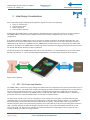
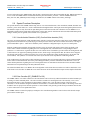
In its simplest model, the AMBE-3000™ can be viewed as two separate components, the Encoder and the Decoder. The
Encoder receives an 8 kHz sampled stream of speech data (16-bit linear, 8-bit Alaw, or 8-bit ulaw) and outputs a stream of
channel data at the desired rate. Simultaneously, the AMBE-3000™ Vocoder Chip receives compressed voice channel data.
This data is (decoded) by the AMBE-3000™ Vocoder Chip, then reconstructed into a digital speech signal and sent to the D/A.
The encoder and decoder functions are fully asynchronous.
The special functions of the AMBE-3000™ chip, such as echo cancellation, voice activation/detection, power mode control,
data/FEC rate selection, etc. can be controlled either through hardware control pins and/or through the Packet interface.
Figure 1 Basic Operation
2.1
A/D – D/A Codec chip Selection
The AMBE-3000™ Vocoder Chip can be configured to transmit and receive digitized speech to and from most linear, a-law, or
u-law A/D-D/A codecs. The format of the incoming and outgoing speech data streams are coupled, that is to say they must be
the same format (16-bit linear, 8-bit Alaw, or 8-bit µlaw). The digitized speech from the external A/D is converted into
compressed digital data (encoded) by the AMBE-3000™ Vocoder Chip and output to the channel interface. Alternatively,
speech data can be sent to/from the AMBE-3000™ vocoder chip via a packet interface.
The choice of the A/D-D/A chip is critical to designing a system with superior voice quality. Given that Alaw and µlaw
companding chips are already incorporating some compression to reduce the number of bits per sample, it is recommended
that, when possible, a 16-bit linear device be used for maximum voice quality. When choosing a device, pay particular
attention to Signal to Noise ratios and Frequency Responses of any filters that may be present on the analog front end of these
chips. Generally speaking, the flatter the frequency response over the voice spectrum (20-4000Hz) the better the overall
system will sound. The Alaw and µlaw interfaces are mainly provided for the design engineer who is trying to fit to preexisting conditions or is under cost savings restraints.
PRELIMINARY
(Subject to Change)
Page 11
DVSI CONFIDENTIAL PROPRIETARY
AMBE-3000™ Vocoder Chip Users Manual
Version 1.00, January, 08
2.2
PRELIMINARY
(Subject to change)
Initial Design Considerations
Vocoder Speech and FEC Rate Selection
2.3
Operating Modes
There are two modes (Codec Mode and Packet Mode) for the AMBE-3000™ vocoder chip. Both modes can take advantage of
the variety of interfaces available.
2.3.1 Codec Mode
In Codec mode the speech data I/O (to/from codec) is a serial stream of samples that uses either the SPI or the McBSP
interface and the channel data is configured into data packets that are sent across either the UART, parallel port, or McBSP
(when not used as the codec interface). When using Codec Mode the speech and channel data use separate interfaces. Packets
containing channel data are sent and received every 20 ms.
2.3.2 Packet Mode
In Packet mode, the speech and channel data use the same interface UART, parallel port, or McBSP serial port. All of the
speech and channel data to/from the AMBE-3000™ is formatted into a packets. (See Section 7). It is the responsibility of the
designed system to extract the speech/channel data from these packets in order to pass the information to/from the
codec/channel interface.
When in packet mode AMBE-3000™ sends a packet in response to every packet received. When a control packet is received
it will respond with a control response packet. When a speech packet is received the AMBE-3000™ responds with a channel
packet. When a channel packet is received it responds with a speech packet.
PRELIMINARY
(Subject to Change)
Page 12
DVSI CONFIDENTIAL PROPRIETARY
Section 2
The voice coding rate as well as the FEC coding rate can be selected individually on the AMBE-3000™. These rates are
selected by using a configuration control packet, or through hardware configuration pins. The hardware configuration pins
provide the user with 48 pre-configured voice/FEC rates. If rates other than these are desired, then a configuration control
packet can be used to configure voice and FEC rates in 50 bps increments.
PRELIMINARY
AMBE-3000™ Vocoder Chip Users Manual
Version 1.00, January, 08
(Subject to change)
Initial Design Considerations
Section 2
2.4
Switching Between Modes via Packets
After reset, the AMBE-3000™ is set to the mode corresponding to the Interface Configuration Pins (see Table 2 Interface
Configurations). The AMBE-3000™ can be switched from Packet Mode to Codec Mode by sending it a START_CODEC
packet and can be switched back into packet mode by sending a STOP_CODEC packet. (See Section 7) The chip can be
configured to start-up in packet mode and control packets can be sent to configure additional settings. After all configuration
packets have been sent to the AMBE-3000™ a START_CODEC packet can be sent to the AMBE-3000™ to put the chip into
Codec Mode and the chip will begin outputting packets every 20ms. At any time the user can send a STOP_CODEC packet
and the AMBE-3000™ will re-enter packet mode and stop outputting channel packets.
2.5
Interface Selection
Basic communication to/from the AMBE-3000™ consists of digitized speech data samples I/O and compressed speech data
I/O. The chip can be configured to use separate interfaces for each of the speech and compressed data can use the same
interface.
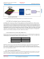
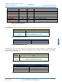
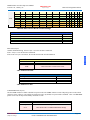
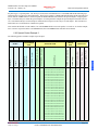
The AMBE-3000™ supports four separate physical interfaces: SPI, UART, parallel port, and McBSP serial port. The user has
the option of selecting the interface for both the Codec and Packet data. This flexibility allows for easy integration with the
system under design. To select which physical interface is to be used for Codec data and for Packet data the AMBE-3000™
provides hardware configuration pins. The available interface combinations are shown in Table 2 Interface Configurations
Physical
Interface
Codec
Interface
SPI
þ
McBSP
þ
Packet
Interface
Description
UART
þ
The SPI Interface is only for Codec Samples
The McBSP Interface can be used for either
Codec Samples OR
Packet Data
The UART Interface is only for Packet Data
Parallel
þ
The Parallel Interface is only for Packet Data
þ
Table 1 Interface Selection
PRELIMINARY
(Subject to Change)
Page 13
DVSI CONFIDENTIAL PROPRIETARY
AMBE-3000™ Vocoder Chip Users Manual
Version 1.00, January, 08
PRELIMINARY
(Subject to change)
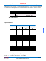
Speech Interface
Packet Interface
SPI
SPI
SPI
McBSP
McBSP
UART
PPT
McBSP
UART
PPT
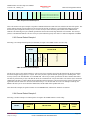
Section 2
Interface Configurations
Configuration Pin #’s
Mode
4
3
2
Codec Mode
0
0
0
Codec Mode
0
0
1
Codec Mode
0
1
0
Codec Mode
0
1
1
Codec Mode
1
0
0
Packet Mode
1
0
1
Packet Mode
1
1
0
Packet Mode
1
1
1
Initial Design Considerations
UART
PPT
McBSP
Table 2 Interface Configurations
The Codec interface can be set to use the SPI or McBSP Interface in Codec Mode or share the same interface as the channel
when operating in Packet mode. The channel interface (compressed data) of the AMBE-3000™ Vocoder Chip is always a
packet format and can be configured to use either a serial (UART or McBSP) or a parallel interface.
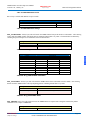
2.5.1 SPI Interface
The serial peripheral interface (SPI) is a high-speed, synchronous serial I/O port that can be used as the speech interface to the
codec. This interface allows a serial bit stream to be transferred between the AMBE-3000™ and an audio codec. The
interface includes four-pins. The SPI interface is designed for speech data only and may be used only in CODEC Mode.
Pin
Pin Name
Direction
Description
27
SPI_CLK
Input
28
SPISTEA
Input
31
SPI_TX_DATA
Input
Serial Transmit Data
32
SPI_RX_DATA
Output
Serial Receive Data
A/D Serial clock.
Table 3 SPI Interface Pins
PRELIMINARY
(Subject to Change)
Page 14
DVSI CONFIDENTIAL PROPRIETARY
AMBE-3000™ Vocoder Chip Users Manual
Version 1.00, January, 08
PRELIMINARY
(Subject to change)
Initial Design Considerations
Section 2
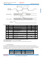
SPI External Timing †‡
NO.
1
MIN
4tc(LCO)‡
MAX
Pulse duration, CODEC_CLK low
0.5tc(SPC)S- 10
0.5tc(SPC)S
tw(CCH)S
Pulse duration, CODEC_CLK high
0.5tc(SPC)S- 10
0.5tc(SPC)S
4§
td(CCL-CRxD)S
Delay time, CODEC_CLK low to
CODEC_Rx_DATA valid
5§
tv(CCH- CRxD)S
Valid time, CODEC_Rx_DATA valid after
CODEC_CLK high
6§
tsu(CTxD -CCH)S
Setup time, CODEC_Tx_DATA before
CODEC_CLK high
7§
tv(CCH- CTxD)S
Valid time, CODEC_Tx_DATA valid after
CODEC_CLK high
tc(CC)S
Cycle time, CODEC_CLK
2§
tw(CCL)S
3§
UNIT
ns
ns
ns
0.375tc(SPC)S- 10
ns
0.75tc(SPC)S
ns
0
ns
0.5tc(SPC)S
ns
† The
MASTER/SLAVE bit (SPICTL.2) is cleared and the CLOCK PHASE bit (SPICTL.3) is cleared.
CODEC clock cycle time = LSPCLK or LSPCLK/(SPIBRR_1)
tc(LCO) = LSPCLK cycle time
§ The active edge of the CODEC_CLK signal referenced is controlled by the CLOCK POLARITY bit (SPICCR.6).
‡ tc(SPC) =
2.5.2 UART Interface
The serial interface supports asynchronous communication of real-time compressed voice data to other asynchronous
peripherals that use the standard non-return-to-zero (NRZ) format. Selection of a serial mode restricts all Packet transfers to
occur through a UART port. The UART interface is designed for packet data. This means in Codec Mode the UART can be
used for channel data only. In Packet mode the UART can be used for both speech data and channel data.
Pin
Pin Name
Direction
Description
111
UART_TX
Output
UART Transmit Data
112
UART_RX
Input
UART Receive Data
PRELIMINARY
(Subject to Change)
Page 15
DVSI CONFIDENTIAL PROPRIETARY
AMBE-3000™ Vocoder Chip Users Manual
Version 1.00, January, 08
PRELIMINARY
(Subject to change)
Initial Design Considerations
Table 4 UART Interface Pins
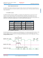
2.5.3 McBSP Interface
The Multichannel Buffered Serial Ports (McBSP) is a synchronous serial communication port. This port can be used to
connect to E1/T1 lines, phone-quality codecs for modem applications or high-quality stereo audio DAC devices. The
beginning of a frame of data is provided by a frame signal. This transmit frame signal and the transmit clock signal are
generated by the AMBE-3000™ Vocoder Chip. In Codec Mode the McBSP interface can be used for either speech data or for
channel data. In Packet Mode the McBSP interface is used for both speech data and channel data.
Pin
Pin Name
Direction
Description
18
McBSP_PKT_RxD
Input
Serial Receive Data
19
McBSP _PKT_TxD
Output
Serial Transmit Data
21
McBSP _PKT_CLKR
Input
Serial Receive Clock
22
McBSP _PKT_FSX
Output
Serial Transmit Frame
23
McBSP _PKT_CLKX
Output
Serial Transmit Clock
24
McBSP _PKT_FSR
Input
Serial Receive Frame
Table 5 McBSP Interface Pins
The serial port packet interface is a synchronous serial communication port. The serial port packet interface consists of 3 input
pins and 3 output pins. Packets are transmitted using data pin McBSP_PKT_TxD, clock pin McBSP_PKT_CLKX, and
framing pin McBSP_PKT_FSX. Packets are received using data pin McBSP_PKT_RxD, clock pin McBSP_PKT_CLKR, and
framing pin McBSP_PKT_FSR.
PRELIMINARY
(Subject to Change)
Page 16
DVSI CONFIDENTIAL PROPRIETARY
Section 2
The AMBE-3000™ transmits formatted packets using pin UART_TX and receives formatted packets using pin UART _RX.
Each serial word transmitted or received uses 8 data bits, no parity bits, and one stop bit. The serial port operates at baud rates
of up to 460800 baud.
AMBE-3000™ Vocoder Chip Users Manual
Version 1.00, January, 08
PRELIMINARY
(Subject to change)
Initial Design Considerations
Section 2
No.
Parameter
M1
M2
M3
M4
tc(CKRX)
tw(CKRXH)
tw(CKRXL)
td(CKRH-FRV)
Cycle time, CLKR/X
Pulse duration, CLKR/X high
Pulse duration, CLKR/X low
Delay time CLKR high to internal FSR valid
M5
td(CKXH-FXV)
Delay time CLKX high to internal FSX valid
M6
tdis(CKXH-DXHZ)
Disable time, CLKX high to DX high impedance
following last data bit
Delay time, CLKX high to DX valid. This applies to all
bits except the first bit transmitted.
M7
M8
M9
M10
td(CKXH-DXV)
ten(CKXH-DX)
td(FXH-DXV)
ten(FXH-DX)
Delay time, CLKX high to DX valid
DXENA = 0
Only applies to first bit transmitted
when in Data Delay 1 or 2
(XDATDLY=01b or 10b) modes
DXENA = 1
Enable time, CLKX high to DX driven
DXENA = 0
Only applies to first bit transmitted
when in Data Delay 1 or 2
(XDATDLY=01b or 10b) modes
DXENA = 1
Delay time, FSX high to DX valid
DXENA = 0
Only applies to first bit transmitted
when in Data Delay 0
(XDATDLY=00b) mode.
DXENA = 1
Enable time, FSX high to DX driven
DXENA = 0
Only applies to first bit transmitted
when in Data Delay 0
(XDATDLY=00b) mode
DXENA = 1
CLKR/X int
CLKR/X int
CLKR/X int
CLKX int
CLKX ext
CLKX int
CLKX ext
CLKX int
CLKX ext
CLKX int
CLKX ext
CLKX int
CLKX ext
FSX int
FSX ext
FSX int
FSX ext
FSX int
FSX ext
FSX int
FSX ext
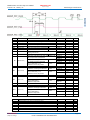
McBSP module cycle time (CLKG CLKX CLKR) range
PRELIMINARY
(Subject to Change)
ns
ns
ns
ns
9
28
8
14
P+8
P + 14
CLKX ext
McBSP module clock (CLKG CLKX CLKR) range
tc(CKRX) Cycle time, CLKR/X
tw(CKRX) Pulse duration, CLKR/X high or CLKR/X low
Unit
2P
D-5§ D+5§
C-5§ C+5§
0
4
3
27
0
4
3
27
8
14
CLKX int
CLKX ext
CLKX int
CLKX ext
CLKX int
NO.
M11
M12
MIN MAX
CLKR/X ext
CLKR/X ext
ns
ns
ns
ns
0
6
P+6
ns
8
14
P+8
P + 14
0
6
P
P+6
MIN MAX
1
20§
50
1
2P
P-7
ns
UNIT
kHz
MHz
ns
ms
ns
ns
Page 17
DVSI CONFIDENTIAL PROPRIETARY
AMBE-3000™ Vocoder Chip Users Manual
Version 1.00, January, 08
PRELIMINARY
(Subject to change)
tr(CKRX) Rise time
CLKR/X
CLKR/X ext
7
ns
M14
tf(CKRX) Fall time, CLKR/X CLKR/X ext 7 ns
M15
tsu(FRH-CKRL) Setup time external FSR high before CLKR low
CLKR int
CLKR ext
18
2
ns
ns
M16
th(CKRL-FRH) Hold time external FSR high after CLKR low
CLKR int
CLKR ext
0
6
ns
ns
M17
tsu(DRV-CKRL)Setup time DR valid before CLKR low
CLKR int
CLKR ext
18
2
ns
ns
M18
th(CKRL-DRV) Hold time DR valid after CLKR low
CLKR int
CLKR ext
0
6
ns
ns
M19
tsu(FXH-CKXL) Setup time external FSX high before CLKX low
CLKR int
CLKR ext
18
2
ns
ns
M20
th(CKXL-FXH) Hold time external FSX high after CLKX low
CLKR int
CLKR ext
0
6
ns
ns
Section 2
M13
Initial Design Considerations
2.5.4 Parallel Interface
Pin #
Description
Direction
33
PACKET_DATA0
I/O
34
PACKET _DATA1
I/O
35
PACKET _DATA2
I/O
36
PACKET _DATA3
I/O
37
PACKET _DATA4
I/O
38
PACKET _DATA5
I/O
40
PACKET_DATA6
I/O
41
PACKET_DATA7
I/O
46
PPT_READ
Input
47
PPT_WRITE
Input
48
PPT_ACK
Output
Description
Parallel Port
Transmit/Receive
Data
PPT Read Request
(Active Low)
PPT Write Request
(Active Low)
PPT Transfer Acknowledge
Table 6 Parallel (PPT) Interface Pins
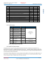
2.5.5 Parallel Port Packet Interface
The parallel interface runs asynchronously and allows all Packet data transfers (including the control functions) to be
performed on an 8-bit wide bus. The parallel port interface (PPT) requires 11 pins total. When parallel port is used for the
Packet interface the UART or the McBSP serial interface can not be used. . The Parallel interface is designed for packet data.
This means in Codec Mode the Parallel interface can be used for channel data only. In Packet mode the Parallel interface can
be used for both speech data and channel data.
The packet data from the AMBE-3000™ is read by setting the pin PPT_READ low, then waiting for the AMBE-3000™ to set
PPT_ACK low. After PPT_ACK goes low, the 8 data pins are valid, after the pins are read PPT_READ should be set high.
After PPT_READ goes high, the AMBE-3000™ will set PPT_ACK high.
PRELIMINARY
(Subject to Change)
Page 18
DVSI CONFIDENTIAL PROPRIETARY
AMBE-3000™ Vocoder Chip Users Manual
Version 1.00, January, 08
PRELIMINARY
(Subject to change)
Initial Design Considerations
To write packet data to the AMBE-3000™ first the data is transferred to the 8 data pins and then the PPT_WRITE pin must be
set low. Then the AMBE-3000™ reads the data from the pins and sets PPT_ACK low. After the AMBE-3000™ sets
PPT_ACK low, PPT_WRITE pin must set high, at which time, the AMBE-3000™ will set PPT_ACK high.
Special Functions Description
The special functions of the AMBE-3000™ chip, such as voice activation/detection, echo cancellation, DTMF, data/FEC rate
selection, power mode control, etc. can be controlled either through hardware control pins and/or through the packet interface.
The hardware inputs are only accessed for input during the first 200 microseconds after a hardware reset on RESETN. For
predictable operation these signals must remain stable over this time period. After this 200 microseconds initialization period
changes on these pins are ignored, unless another reset is performed.
2.6.1 Voice Activation Detection (VAD), Comfort Noise Insertion (CNI)
The Voice Activation Detection (VAD) algorithm along with the Comfort Noise Insertion (CNI) feature of the AMBE-3000™
chip performs useful functions in systems trying to convert periods of silence, that exist in normal conversation, to savings in
system bandwidth or power. VAD can be enabled by either a hardware configuration pin or as part of a control packet.
With the VAD functions enabled, when periods of silence occur, the encoder will output a silence frame (in-band). This
silence frame contains information regarding the level of background noise, which allows the corresponding decoder to
synthesize a “Comfort Noise” signal at the other end. The comfort noise is intended to give the listener the feeling that the call
is still connected, as opposed to producing absolute silence, which can give the impression that, the call has been “dropped”.
The decoder will produce a comfort noise frame if it receives an in-band silence frame (produced only by an encoder with
VAD enabled). The synthesis of a Comfort Noise frame by the decoder is not dependant on VAD being enabled.
If the VAD features are being used to reduce transmit power during times of conversational silence, DVSI recommends that a
silence frame be transmitted at the start of the period and approximately each 500-1000 milliseconds thereafter. This is to
ensure that the parameters regarding the levels of background noise are transmitted to the decoder for the smoothest audible
transitions between synthesized speech and synthesized silence.
The silence threshold value is -25 dBm0 in the VAD algorithm. Each frame that exceeds this level will be classified as voice.
If the frame level is less than -25 dBm0 the voice/silence decision will be determined based upon various adaptive thresholds.
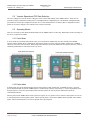
2.6.2 Echo Canceller (EC_ENABLE Pin 120)
The AMBE-3000™ voice coder contains an echo canceller that can be selectively enabled or disabled via either hardware pin
or setting of control command packet. The echo canceller is suitable for canceling the local echo caused by a 2-to-4 wire
hybrid and can achieve echo cancellation of approximately 30dB or more. Only the linear portion of the echo can be
cancelled, so circuits should be designed to minimize non-linearities. The Echo Return Loss (ERL) of the analog circuit must
be 6dB or more for proper echo canceller operation. Linear CODECs will generally provide better performance than mu-law
or A-law codecs due to lower quantization noise.
The AMBE-3000™ Vocoder Chip employs an adaptive echo cancellation algorithm to cancel echoes of the decoder output
present at the encoder input.
PRELIMINARY
(Subject to Change)
Page 19
DVSI CONFIDENTIAL PROPRIETARY
Section 2
2.6
AMBE-3000™ Vocoder Chip Users Manual
Version 1.00, January, 08
PRELIMINARY
(Subject to change)
Initial Design Considerations
Section 2
Figure 2 B Typical Echo Path
The echo canceller can be activated either through the hardware pin, or through the Packet interface .
2.6.3 DTMF Dual Tone Multiple Frequency, Detection and Generation
The AMBE-3000™ Vocoder Chip is capable of detecting, transmitting, and synthesizing DTMF tones. When the encoder
detects DTMF tones, the output packet will have a special DTMF ID word in a control packet, and the Voice Data field will
contain the DTMF tone data. The DTMF tone detected along with amplitude information is placed in the DTMF control word.
Additionally, the encoder passes the DTMF data in-band (within the regular voice data bits) so that normal DTMF tones pass
seamlessly from the encoder to the decoder for synthesis. The decoder synthesizes a DTMF tone in response to reception of an
in-band DTMF tone frame or by setting the DTMF control word in the control packet. When this Voice Data is received by an
AMBE-3000™ Vocoder Chip decoder, it will regenerate the inband tone. The AMBE-3000™ Vocoder Chip can also generate
“Dual Tones” at many different frequencies. Each tone packet generates 20 milliseconds of output tones. The length of the
output tones can be extended by repeating the tone packet. DTMF is always enabled.
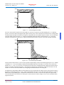
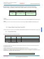
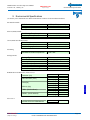
2.6.4 Soft Decision Error Correction (SD_ENABLE Pin 5)
Significant improvement in FEC performance can be added by setting up a receiver so that the demodulator is making a finer
estimation of the received energy prior to sending it to the decoder, this is called soft-decision decoding. The AMBE-3000™
vocoder chip utilizes a 4-bit soft decision decoder. The bits are defined as follows:
Decision Value (Binary)
0000
0111
1000
1111
Interpretation
Most confident 0
…
…
Most confident 1
Table 7 Soft Decision Error Correction
Enabling the soft-decision error correction does nothing to the encoder packet. The packet will look like a normal encoded
packet. The user must implement circuitry at the receive end of the channel for making a finer (4 bit) estimation of the
received energy. The AMBE-3000™ decoder packet structure is altered to the point where the decoder expects each voice
data bit of the encoded packet to be represented by 4 soft decision (SD) bits. The decoder will make the decision of whether or
not a 1 or a 0 is represented by the SD bits.
2.6.5
Skew Control (SK_ENABLE Pin 6)
The AMBE-3000™ Vocoder chip processes speech in voice frames that are approximately 20 ms in duration. Skew Control
can provide the designer with flexibility in dealing with clock drift. The AMBE-3000™ Vocoder chip skew control feature
allows the vocoder chip to compensate for drift between the frame and sample rate clocks.
PRELIMINARY
(Subject to Change)
Page 20
DVSI CONFIDENTIAL PROPRIETARY
AMBE-3000™ Vocoder Chip Users Manual
Version 1.00, January, 08
PRELIMINARY
(Subject to change)
Initial Design Considerations
Codec Mode
When skew control is enabled, the AMBE-3000™ adjusts the frame boundaries so that they occur on the rising edge of the
TXRQST signal. The frame size can vary between 156 and 164 samples.
2.6.6
Noise Suppressor (NS_ENABLE Pin 7)
The integrated Noise suppressor feature of the AMBE-3000™ is used to reduce the effect of background noise in the encoder
input signal. The Noise suppressor is applied to both silence frames and voice frames, but not tone frames. When the noise
suppressor is started it may take up to a few seconds to converge allowing for it do begin fully working.
2.6.7 Low Power Mode
In order to minimize power consumption requirements, during periods of inactivity the AMBE-3000™ Vocoder Chip enters
into a low-power state. In this mode the AMBE-3000™ Vocoder Chip will return to normal operation “wake-up” when it
receives packet data (serial or parallel) or if the chip is reset. Low power mode can also be set through hardware pin control or
configuration control packet.
PRELIMINARY
(Subject to Change)
Page 21
DVSI CONFIDENTIAL PROPRIETARY
Section 2
Packet Mode Skew Control Enable
In packet mode the normal length is 160 of the input speech packets is 160 samples. However this can vary between 156 and
164 samples in length. Output speech packets can also vary in length from 156 to 164 samples.
Digital Voice Systems, Inc.
AMBE-3000™ Vocoder Chip Users Manual
Version 1.00, January, 08
The Speech Compression Specialists
PRELIMINARY
(Subject to change)
Hardware Information
Hardware Information
3 Hardware Information
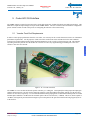
The AMBE-3000™ Vocoder Chip uses Texas Instruments TMS320F2811 core. The TMS320F2811 DSP
Design uses High-Performance Static CMOS Technology with a low-power Core (1.8-V @135 MHz), and 3.3-V I/O. This
generation of TI DSPs, are highly integrated, high-performance solutions for demanding control applications. For more details
on handling, electrical characteristics, packaging, or timing constraints please refer to the TMS320F2811manual found at
http://focus.ti.com/docs/prod/folders/print/tms320f2811.html.
The AMBE-3000™ uses the TM320F2811PBK core. For more details on handling, electrical characteristics, packaging, or
timing constraints please refer to the TI manual found at http://www-s.ti.com/sc/psheets/sprs039c/sprs039c.pdf (Adobe
Acrobat). To avoid damage from the accumulation of a static charge, industry standard electrostatic discharge precautions and
procedures must be employed during handling and mounting.
Section 3
3.1 Special Handling Instructions
S
PRELIMINARY
(Subject to Change)
Page 22
DVSI CONFIDENTIAL PROPRIETARY
AMBE-3000™ Vocoder Chip Users Manual
Version 1.00, January, 08
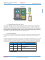
3.2
PRELIMINARY
(Subject to change)
Hardware Information
Hardware Information
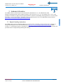
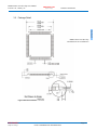
Package Detail
Section 3
AMBE-3000™ Vocoder Chip
All Dimensions are in millimeters
S
Figure 3 Mechanical Details
PRELIMINARY
(Subject to Change)
Page 23
DVSI CONFIDENTIAL PROPRIETARY
AMBE-3000™ Vocoder Chip Users Manual
Version 1.00, January, 08
3.3
PRELIMINARY
(Subject to change)
Hardware Information
Hardware Information
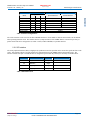
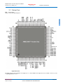
Package Type
PBK = 128-pin LQFP
LQFP = Low-Profile Quad Flatpack
Section 3
S
Figure 4 Pins Out
All digital inputs are TTL-compatible. All outputs are 3.3 V with CMOS levels. Inputs are not 5-V tolerant. A 100-? A (or 20? A) pullup/pulldown is used.
PRELIMINARY
(Subject to Change)
Page 24
DVSI CONFIDENTIAL PROPRIETARY
AMBE-3000™ Vocoder Chip Users Manual
Version 1.00, January, 08
3.4
PRELIMINARY
(Subject to change)
Hardware Information
Hardware Information
AMBE-3000™ Chip Markings
Section 3
AMBE-3000-10
AMBE-3000™ = The DVSI device part number.
– 10 = Chip type is 128 pin LQFP (Low-Profile Quad Flatpack)
– 11 = Chip type is BGA (Ball Grid Array)
DVSI = Digital Voice Systems, Incorporated
ADW-0BAJ9DW = Internal Texas Instruments part number for the AMBE-3000™
A = WF Code
S
D = Die Rev Code
W = Die Shrink Code
0BAJ9DW = Lot Trace Code
0B = 2 Digit YR/MO Code (Updated Monthly)
AJ9D = Assy Lot
W = Assy Site Code
PRELIMINARY
(Subject to Change)
Page 25
DVSI CONFIDENTIAL PROPRIETARY
AMBE-3000™ Vocoder Chip Users Manual
Version 1.00, January, 08
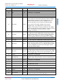
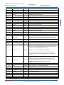
3.5
PRELIMINARY
(Subject to change)
Hardware Information
Hardware Information
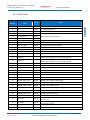
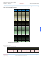
Pin Out Table
Pin
Number
Pin Descriptive
Name
Pin
Directio
n
Notes
Section 3
1
3v3
PWR
2
3
4
5
6
7
8
9
IF_SELECT0
IF_SELECT1
IF_SELECT2
SD_ENABLE
SK_ENABLE
NS_ENABLE
CP_ENABLE
CP_SELECT
Input
Input
Input
Input
Input
Input
Input
Input
10
VREF_1V
-
11
VREF_2V
-
12
13
14
15
16
Ground
3v3
3v3
Ground
ADCRESEXT
GND
PWR
PWR
GND
-
Voltage Reference Output (1 V). Requires a low ESR (50 m??- 1.5 ?)
ceramic bypass capacitor of 10 µF to analog ground.
Voltage Reference Output (2 V). Requires a low ESR (50 m??- 1.5 ?)
ceramic bypass capacitor of 10 µF to analog ground.
Analog I/O Ground Pin
3.3 V I/O Digital Power
3.3 V I/O Digital Power
Analog I/O Ground Pin
ADC External Current Bias Resistor (24.9kO) to Ground
18
McBSP_PKT_RxD
Input
McBSP Serial Channel Receive Data
19
McBSP_PKT_TxD
Output
McBSP Serial Channel Transmit Data
21
McBSP_PKT_CLKR
I/O PU
McBSP Serial Channel CLKR
22
McBSP_PKT_FSX
I/O PU
McBSP Serial Channel FSX
23
McBSP_PKT_CLKX
I/O PU
McBSP Serial Channel CLKX
24
McBSP_PKT_FSR
I/O PU
McBSP Serial Channel FSR
27
SPI_CLK
Input
28
SPISTEA
Input
31
SPI_TX_DATA
Interface selection configuration
Soft Decision FEC enable / disable
Skew Control enable / disable
Noise Suppression enable / disable
Companding enable / disable
Select a_law / u_law
This is the Serial clock from Codec. It also should be connected to
SPI_CLK_IN
This is the framing signal generated from SPIGENSTEA. This pin
is connected to Pin #77.
PCM Data from AMBE-3000™ to D/A Converter
PRELIMINARY
(Subject to Change)
Page 26
DVSI CONFIDENTIAL PROPRIETARY
S
Output
3.3 V I/O Digital Power
AMBE-3000™ Vocoder Chip Users Manual
Version 1.00, January, 08
PRELIMINARY
(Subject to change)
SPI_RX_DATA
Input
PCM Data from A/D Converter to AMBE-3000™
33
PACKET_DATA0
I/O
Parallel Packet Data
34
PACKET _DATA1
I/O
Parallel Packet Data
35
PACKET _DATA2
I/O
Parallel Packet Data
36
PACKET _DATA3
I/O
Parallel Packet Data
37
PACKET _DATA4
I/O
Parallel Packet Data
38
PACKET _DATA5
I/O
Parallel Packet Data
40
PACKET_DATA6
I/O
Parallel Packet Data
41
PACKET_DATA7
I/O
Parallel Packet Data
Section 3
32
Hardware Information
Hardware Information
PKT_RX_WAKE
Input
44
N/C
-
45
N/C
-
CURRENTLY UNASSIGNED
46
PPT_READ
Input
Read data from PACKET_DATA pins
47
PPT_WRITE
Input
Write data to PACKET_DATA pins
48
PPT_ACK
Output
50
51
N/C
N/C
-
52
3v3
PWR
54
N/C
-
No Connection
55
N/C
-
No Connection
57
N/C
-
58
X1/XCLKIN
No Connection
29.4912 MHz Clock input. This pin is also used to feed an external
clock. The 28x can be operated with an external clock source,
provided that the proper voltage levels are driven on the
X1/XCLKIN pin. It should be noted that the X1/XCLKIN pin is
referenced to the 1.8-V core digital power supply (VDD), rather
than the 3.3-V I/O supply (VDDIO). A clamping diode may be used
to clamp a buffered clock signal to ensure that the logic-high level
does not exceed VDD (1.8 V) or a 1.8-V oscillator may be used.
60
CODEC_RESETn
61
N/C
Input
Output
-
No Connection
No Connection
3.3-V Flash Core Power Pin. This pin should be connected to 3.3 V
at all times after power-up sequence requirements have been met.
Output to Reset the Codec
No Connection
PRELIMINARY
(Subject to Change)
Page 27
DVSI CONFIDENTIAL PROPRIETARY
S
43
When the UART interface issued and low-power mode is enabled,
this pin must be connected to UART_RX. This is used to make
sure that standby mode is not entered while UART_RX is active.
When the McBSP packet interface is used this signal should be
connected to the inverted McBSP_PKT_FSR signal to make sure
that standby mode is not entered while McBSP_PKT_RxD is active.
CURRENTLY UNASSIGNED
AMBE-3000™ Vocoder Chip Users Manual
Version 1.00, January, 08
PRELIMINARY
(Subject to change)
Hardware Information
Hardware Information
N/C
-
65
N/C
I/O
CURRENTLY UNASSIGNED
66
N/C
-
CURRENTLY UNASSIGNED
67
N/C
-
CURRENTLY UNASSIGNED
Channel Transmit Data Strobe TXRQST is a 20 ms frame signal
used to control the encoder timing, when skew control is enabled. It
must be high for at least 250 us. The period must be 20+/-1 ms.
When the encoder schedule is relative to TXRQST, the time
between rising edges is used to compute the subframe lengths.
68
TX_RQST
Input
69
TX_RDY
Output
70
I2C_DATA
Output
2
71
I C_CLK
72
RX_RQST
Output
Input
No Connection
Section 3
64
If skew control is not enabled, TXRQST can be used as a
handshake signal. The AMBE-3000™ Vocoder Chip sets
TXRDY=1 when a packet is ready for transmission. The AMBE3000™ Vocoder Chip then waits for TXRQST=1 before it sends the
packet. If handshaking is not desired, then you can hold
TXRQST=1 at all times.
Transmit Packet Ready.
Goes high as soon as the AMBE-3000™ Vocoder Chip is ready to
transmit a channel packet. Goes low after the packet output begins
Regardless of the configuration, whenever the AMBE-3000™
Vocoder Chip has a packet ready for transmission it sets TXRDY=1
I2C_DATA (output from AMBE-3000™ Vocoder Chip to codec)
I2C_CLK (output from AMBE-3000™ Vocoder Chip to codec)
RXRQST is a 20 ms frame signal used to control the encoder
timing, when skew control is enabled. It must be high for at least
250 us. The period must be 20+/-1 ms. When the decoder schedule
is relative to RXRQST, the time between rising edges is used to
compute the subframe lengths.
S
Ready to Receive Packet.
Goes high when the decoder packet buffer is empty and the AMBE3000™ Vocoder Chip is ready to receive the next packet. Goes low
after the AMBE-3000™ Vocoder Chip starts receiving a packet.
CURRENTLY UNASSIGNED
Required when using the SPI interface. This is used to generate the
SPISTEA signal. This pin should be connected to SPI_STEA (pin#
28).
CURRENTLY UNASSIGNED
75
RX_RDY
Output
76
I/O Pin
Output
77
SPIGENSTEA
Output
78
N/C
Input
79
I/O Pin
Input
80
SPI_FS
Input
81
I/O Pin
I/O
CURRENTLY UNASSIGNED
Must be connected to the inverted frame sync signal from the codec
if the SPI interface is used.
CURRENTLY UNASSIGNED
84
I/O Pin
I/O
CURRENTLY UNASSIGNED
85
I/O Pin
I/O
86
SPI_CLK_IN
CURRENTLY UNASSIGNED
For SPI Interface to function properly this pin must be connect to
the Serial clock from Codec. (pin #27 SPI_CLK)
Input
PRELIMINARY
(Subject to Change)
Page 28
DVSI CONFIDENTIAL PROPRIETARY
AMBE-3000™ Vocoder Chip Users Manual
Version 1.00, January, 08
PRELIMINARY
(Subject to change)
-
Hardware Information
Hardware Information
87
N/C
89
I/O Pin
I/O
CURRENTLY UNASSIGNED
90
I/O Pin
I/O
CURRENTLY UNASSIGNED
91
I/O Pin
I/O
CURRENTLY UNASSIGNED
92
93
N/C
N/C
96
97
98
99
100
N/C
Ground
N/C
N/C
N/C
GND
-
101
I/O Pin
Output
105
N/C
106
SPI_WAKE
Input
107
UART_RTS
Input
No Connection
Must be connected to the inverted frame sync signal from the codec
if the SPI interface is used and Low Power Mode is enabled. The
signal is used to wake the AMBE-3000™ from stand-by mode.
UART Ready to send
108
UART_CTS
Input
UART Clear to send
-
No Connection
No Connection
Section 3
-
No Connection
No Connection
Must be connected to ground
No Connection
No Connection
No Connection
CURRENTLY UNASSIGNED
This pin must be held high at reset, in order to select the desired
boot mode. If this pin is held high at reset, then we will branch to
the code in ROM/Flash and begin executing.
UART_TX
Output
112
UART_RX
Input
113
114
115
116
117
118
119
120
121
RESETn
1v8
VSS1
N/C PIN
VSSA2
VDDA2
ES_ENABLE
EC_ENABLE
RATE5
Input
PWR
GND
GND
PWR
Input
Input
Input
(see table 3-4 of the TMS320F2811 Data Manual)
After reset the pin gets configured as a UART transmit pin.
Channel Transmit Data from AMBE-3000™ SCI asynchronous
serial port
Channel Receive Data to AMBE-3000™ asynchronous serial port.
When low-power mode is enabled, UART_RX must be connected
to PKT_RX_WAKE. If the MCBSP packet interface is used
instead of the UART Packet interface, and low power mode is
enabled then this must be connected to the inverted
McBSP_PKT_FSR signal (pin #24).
AMBE-3000™ Reset pin. Active LOW
Supply Voltage 1.8-V Core Digital Power Pins
Analog I/O Ground Pin
Reserved Must be left unconnected
Analog I/O Ground Pin
3.3 V I/O Digital Power
Echo Suppressor enable / disable
Echo Canceller enable / disable
Vocoder Bit Rate Control Words
PRELIMINARY
(Subject to Change)
S
111
Page 29
DVSI CONFIDENTIAL PROPRIETARY
AMBE-3000™ Vocoder Chip Users Manual
Version 1.00, January, 08
PRELIMINARY
(Subject to change)
Hardware Information
Hardware Information
RATE4
RATE3
RATE2
RATE1
RATE0
Ground
Ground
Input
Input
Input
Input
Input
GND
GND
Connect to analog ground
Analog I/O Ground Pin
17, 26, 30,
39, 53, 59,
62, 73, 88,
95, 103, 109
Ground
GND
Core and Digital I/O Pins to Ground.
20, 29, 42,
56, 63, 74,
82, 94, 102,
110
1v8
PWR
Supply Voltage 1.8-V Core Digital Power Pins.
25, 49, 83,
104
3v3
PWR
3.3 V I/O Digital Power Pins.
Section 3
122
123
124
125
126
127
128
Table 8 Pinout List
NOTE:
Other than the power supply pins, no pin should be driven before the 3.3-V rail has reached recommended operating
conditions. However, it is acceptable for an I/O pin to ramp along with the 3.3-V supply.
S
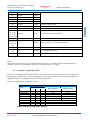
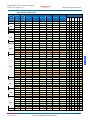
3.6
Hardware Configuration Pins
There is a set of configuration pins that allows the user to set-up the most common chip configurations. The chip boots up
according to the configuration pins. Then after booting up, if any configuration packets are received, the configuration is
changed accordingly. The configuration pins are only looked at boot time.
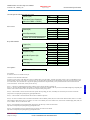
Hardware Configuration Pins for Interface Selection
Interface Configurations
Mode
Configuration Pin #’s
4
3
2
Codec Mode
0
0
0
Codec Mode
0
0
1
Codec Mode
0
1
0
Codec Mode
0
1
1
Codec Mode
1
0
0
Packet Mode
1
0
1
Packet Mode
1
1
0
Packet Mode
1
1
1
Speech Interface
Channel Interface
SPI
SPI
SPI
McBSP
McBSP
UART
PPT
McBSP
UART
PPT
UART
PPT
McBSP
Table 9 Interface Configuration Settings
PRELIMINARY
(Subject to Change)
Page 30
DVSI CONFIDENTIAL PROPRIETARY
AMBE-3000™ Vocoder Chip Users Manual
Version 1.00, January, 08
Digital Voice Systems, Inc.
PRELIMINARY
(Subject to change)
The Speech Compression Specialists
Electrical Characteristics and Requirements
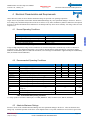
4 Electrical Characteristics and Requirements
Unless otherwise noted, the list of absolute maximum ratings are specified over operating temperature
ranges. Stresses beyond those listed under Absolute Maximum Ratings may cause permanent damage to the device. These are
stress ratings only and functional operation of the device at these or any other conditions beyond those indicated is not implied.
Exposure to absolute-maximum-rated conditions for extended periods may affect device reliability. All voltage values are with
respect to Vss.
4.1
Normal Operating Conditions
Section 4
Normal Operating Conditions
Operating Voltage
1.8-V Core, (135 MHz), 3.3-V I/O
Operating Ambient Temperature Range
-40°C to 85°C
Storage Temperature Range
-65°C to 150°C
Junction Temperature Range
-40°C to 150°C
Table 10 Normal Operating Conditions
Long-term high-temperature storage and/or extended use at maximum temperature conditions may result in a reduction of
overall device life. For additional information, see IC Package Thermal Metrics Application Report (TI literature number
SPRA953) and Reliability Data for additional information, see IC Package Thermal Metrics Application Report and Reliability
Data (TI literature number SPRA953).
4.2
Recommended Operating Conditions
VDDIO
VDD, VDD1
VSS
VDDA1, VDDA2,
VDD3VFL
fSYSCLKOUT
VIH
VIH
VIL
VIL
IOH
IOH
IOL
IOL
Parameter
Device Supply Voltage, I/O
Device Supply Voltage, CPU 1.8 V (135MHz)
Supply Voltage, GND
AVDDREFBG, VDDAIO ADC supply voltage
Flash programming supply voltage
Device clock frequency (system clock) VDD = 1.8 V ± 5%
High-level input voltage All inputs except X1/XCLKIN
High-level input voltage X1/XCLKIN (@50uA max)
Low-level input voltage All inputs except X1/XCLKIN
Low-level input voltage X1/XCLKIN (@50uA max)
High-level output current source current, VOH = 2.4 V
High-level output current source current, VOH = 2.4 V
(Group 2)
Low-level output sink current VOL = VOL MAX
Low-level output sink current VOL = VOL MAX (Group 2)
Min
3.14
1.71
3.14
3.14
2
Nom
3.3
1.8
0
30.3
30.3
Max
3.47
1.89
3.47
3.47
135
Unit
V
V
V
V
2.0 VDDIO
0.7 VDD
0.8
0.3 VDD
-4
MHz
V
V
V
V
mA
-8
mA
4
8
mA
mA
Table 11 Recommended Operating Conditions
†† Group 2 pins are as follows: XINTF pins, T1CTRIP_PDPINTA TDO, XCLKOUT, XF, EMU0, and EMU1.
4.3
Absolute Maximum Ratings
Stresses in excess of the Absolute Maximum Ratings can cause permanent damage to the device. These are absolute stress
ratings only. Functional operation of the device is not implied at these or any other conditions in excess of those given in the
PRELIMINARY
(Subject to Change)
Page 31
DVSI CONFIDENTIAL PROPRIETARY
AMBE-3000™ Vocoder Chip Users Manual
Version 1.00, January, 08
PRELIMINARY
(Subject to change)
Electrical Characteristics and Requirements
operational sections of the data sheet. Exposure to Absolute Maximum Ratings for extended periods can aversely affect device
reliability.
Absolute Maximum Ratings
Supply voltage range, VDDIO, VDD3VFL, VDDA1, VDDA2, VDDAIO, and AVDDREFBG
Supply voltage range, VDD, VDD1
Input voltage range,VIN
Output voltage range, VO
Input clamp current IIK (VIN < 0 or VIN > VDDIO)†
Output clamp current IOK (VO < 0 or VO > VDDIO)
-0.3 V to 4.6 V
-0.5 V to 2.5 V
-0.3 V to 4.6 V
-0.3 V to 4.6 V
± 20 mA
± 20 mA
Table 12 Absolute Maximum Ratings
4.4
Section 4
†Continuous clamp current per pin is ± 2 mA
Thermal Resistance Characteristics
PsiJT
T JA
T JC
Thermal Resistance Characteristics
0.271°C/W
41.65°C/W
10.76°C/W
Table 13 Thermal Resistance Characteristics
Unless otherwise noted, the list of absolute maximum ratings are specified over operating temperature ranges. Stresses beyond
those listed under Absolute Maximum Ratings may cause permanent damage to the device. These are stress ratings only and
functional operation of the device at these or any other conditions beyond those indicated is not implied. Exposure to absolutemaximum-rated conditions for extended periods may affect device reliability. All voltage values are with respect to Vss.
4.5
Power Sequencing Requirements
The AMBE-3000™ vocoder chip silicon requires dual voltages (1.8-V and 3.3-V) to power up the CPU, Flash, ROM, ADC,
and the I/Os. To ensure the correct reset state for all modules during power up, there are some requirements to be met while
powering up/powering down the device.
Enable power to all 3.3-V supply pins (VDDIO, VDD3VFL, VDDA1/VDDA2/VDDAIO/AVDDREFBG) and then ramp 1.8
V (VDD/VDD1) supply pins. 1.8 V (VDD/VDD1) should not reach 0.3 V until VDDIO has reached 2.5 V. This ensures the
reset signal from the I/O pin has propagated through the I/O buffer to provide power-on reset to all the modules inside the
device.
In other words, 3.3-V and 1.8-V can ramp together.
4.6
Power-Down Sequencing:
During power-down, the device reset should be asserted low (8 µs, minimum) before the VDD supply reaches 1.5 V. This will
help to keep on-chip flash logic in reset prior to the VDDIO/VDD power supplies ramping down. It is recommended that the
device reset control from “Low-Dropout (LDO)” regulators or voltage supervisors be used to meet this constraint. LDO
regulators that facilitate power-sequencing (with the aid of additional external components) may be used to meet the power
sequencing requirement.
Option 1:
In this approach, an external power sequencing circuit enables VDDIO first, then VDD and VDD1 (1.8 V or
PRELIMINARY
(Subject to Change)
Page 32
DVSI CONFIDENTIAL PROPRIETARY
AMBE-3000™ Vocoder Chip Users Manual
Version 1.00, January, 08
PRELIMINARY
(Subject to change)
Electrical Characteristics and Requirements
1.9 V). After 1.8 V (or 1.9 V) ramps, the 3.3 V for Flash (VDD3VFL) and ADC (VDDA1/VDDA2/AVDDREFBG)
modules are ramped up. While option 1 is still valid, TI has simplified the requirement. Option 2 is the
recommended approach.
Option 2:
Enable power to all 3.3-V supply pins (VDDIO, VDD3VFL, VDDA1/VDDA2/VDDAIO/AVDDREFBG) and then
ramp 1.8 V (or 1.9 V) (VDD/VDD1) supply pins.
1.8 V or 1.9 V (VDD/VDD1) should not reach 0.3 V until VDDIO has reached 2.5 V. This ensures the reset
signal from the I/O pin has propagated through the I/O buffer to provide power-on reset to all the modules
inside the device. See Figure 6- 10 for power-on reset timing.
4.7
Signal Transition Levels
Input levels are as follows 0.8 V (VIL) and 2.0 V (VIH)
Input transition times are specified as follows:
For a high-to-low transition on an input signal, the level at which the input is said to be no longer high is below VIH(MIN) and
the level at which the input is said to be low is VIL(MAX) and lower.
For a low-to-high transition on an input signal, the level at which the input is said to be no longer low is above VIL(MAX) and
the level at which the input is said to be high is VIH(MIN) and higher.
PRELIMINARY
(Subject to Change)
Page 33
DVSI CONFIDENTIAL PROPRIETARY
Section 4
Note that some of the signals use different reference voltages, see the recommended operating conditions table. Output levels
are driven to a minimum logic-high level of 2.4 V and to a maximum logic-low level of 0.4 V.
Output transition times are specified as follows:
For a high-to-low transition, the level at which the output is said to be no longer high is below VOH(MIN) and the level at
which the output is said to be low is VOL(MAX) and lower.
For a low-to-high transition, the level at which the output is said to be no longer low is above VOL(MAX) and the level at
which the output is said to be high is VOH(MIN) and higher.
Digital Voice Systems, Inc.
AMBE-3000™ Vocoder Chip Users Manual
Version 1.00, January, 08
PRELIMINARY
(Subject to change)
The Speech Compression Specialists
Codec A/D / D/A Interface
5 Codec A/D / D/A Interface
The AMBE-3000™ Vocoder Chip operates with a speech data sample rate of 8kHz for both the A/D and D/A interfaces. This
8kHz data is input and output using a serial port on the AMBE-3000™. The user can choose between hardware configuration
pins or software control in order to the process of configuring the interface to the A/D-D/A chip.
5.1
Vocoder Front End Requirements
In order to ensure proper performance from the voice coder, it is necessary for the vocoder front end to meet a set of minimum
performance requirements. For the purposes of this section the vocoder front end is considered to be the total combined
response between microphone/speaker and the digital PCM interface to the vocoder, as shown in Figure 2-B. This includes
any analog electronics plus the A-to-D and D-to-A converters as well as any digital filtering performed prior to the voice
encoder or after the voice decoder.
Section 5
Figure 2 - B. Vocoder Front End
The AMBE+™ voice encoder and decoder operate with unity (i.e. 0 dB) gain. Consequently the analog input and output gain
elements shown in Figure 2 are only used to match the sensitivity of the microphone and speaker with the A-to-D converters
and D-to-A converters, respectively. It is recommended that the analog input gain be set such that the RMS speech level under
nominal input conditions is 25 dB below the saturation point of the A-to-D converter (+3 dBm0). This level, which equates to
-22 dBm0, is designed to provide sufficient margin to prevent the peaks of the speech waveform from being clipped by the Ato-D converter.
PRELIMINARY
(Subject to Change)
Page 34
DVSI CONFIDENTIAL PROPRIETARY
AMBE-3000™ Vocoder Chip Users Manual
Version 1.00, January, 08
PRELIMINARY
Codec A/D / D/A Interface
(Subject to change)
+2 dB
-1 dB
-2 dB
-18 dB
-35 dB
-40 dB
0 200 400
3000 3400 4000 4600
8000
freq (Hz)
Figure 2 - C. Front End Input Filter Mask
+2 dB
-1 dB
-2 dB
-18 dB
-40 dB
-60 dB
3000 3400 4000
0 200
Figure 2 - D.
4600
8000
freq (Hz)
Front End Output Filter Mask
This document assumes that the A-to-D converter produces digital samples where the maximum digital input level (+3 dBm0)
is defined to be +/- 32767, and similarly, that the maximum digital output level of the D-to-A converter occurs at the same
digital level of +/- 32767. If a converter is used which does not meet these assumptions then the digital gain elements shown
in Figure 2 should be adjusted appropriately. Note that these assumptions are automatically satisfied if 16 bit linear A-to-D
and D-to-A converters are used, in which case the digital gain elements should be set to unity gain.
An additional recommendation addresses the maximum noise level measured at the output reference points shown in Figure 2B with the corresponding inputs set to zero. DVSI recommends that the noise level for both directions should not exceed -60
dBm0 with no corresponding input. In addition the isolation from cross talk (or echo) from the output to the input should
exceed 45 dB which can be achieved via either passive (electrical and/or acoustic design) or active (echo cancellation and/or
suppression) means.
PRELIMINARY
(Subject to Change)
Page 35
DVSI CONFIDENTIAL PROPRIETARY
Section 5
The voice coder interface requires the A-to-D and D-to-A converters to operate at an 8 kHz sampling rate (i.e. a sampling
period of 125 microseconds) at the digital input/output reference points. This requirement necessitates the use of analog filters
at both the input and output to eliminate any frequency components above the Nyquist frequency (4 kHz). The recommended
input filter mask is shown in Figure 2 - C, and the recommended output filter mask is shown in Figure 2 - D. For proper
operation, the shaded zone of the respective figure should bound the frequency response of the front-end input and output.
Digital Voice Systems, Inc.
AMBE-3000™ Vocoder Chip Users Manual
Version 1.00, January, 08
The Speech Compression Specialists
PRELIMINARY
(Subject to change)
Data and Configuration Packets
6 Data and Configuration Packets
6.1
Overview
Interfacing to the AMBE-3000™ chip is engineered to provide as much flexibility as possible. The AMBE-3000™ chip
always uses a packet format for the compressed voice data bits and for the chip configuration/control. The packets can be
transferred using the UART port, parallel port or McBSP serial port for its physical interface based on the setting of hardware
configuration pins. Packets are designed such that they can be as small as possible with no need to send and receive dummy
data.
The AMBE-3000™ chip uses packets whether it is running in Codec Mode or Packet Mode. When in Codec Mode the packets
are used for communicating with the AMBE-3000™ Vocoder chip to configure the vocoder, poll vocoder status information,
as well as, transferring compressed voice data bits from the encoder or to the decoder. When running in Packet Mode the
packets provide the same capabilities as Codec Mode plus they have the ability to transfer speech data samples to/from the
encoder.
Every packet includes a HEADER that consists of a START byte for identification of the beginning of the packet, LENGTH
data to indicate how many bytes are in the packet and a TYPE byte that specifies what to do with the packet. Packets are
processed in a first-in-first-out manner.
Codec Mode Operation
When the AMBE-3000™ Vocoder Chip is in Codec Mode the chip uses separate interfaces for the digitized speech data
samples and the compressed data bits. In this mode the AMBE-3000™ Vocoder Chip automatically sends out compressed data
bits (channel data) packets every 20ms and expects to receive compressed data bits (channel data) packets every 20ms. The
timing of the data transfer depends on the Codec clock.
6.3
Packet Mode Operation
In Packet Mode the AMBE-3000™ Vocoder Chip uses the same interface for the digitized speech data samples and the
compressed data bits. In this mode, when the AMBE-3000™ Vocoder Chip receives packets, it processes the packets and
sends response packets as soon as the data is ready. The AMBE-3000™ Vocoder Chip sends response packets in the same
order that the packets are received. The AMBE-3000™ Vocoder Chip maintains a FIFO for received packets and a separate
FIFO for packets that are awaiting transmission. The FIFOs are each large enough to accommodate up to two speech packets
and two channel packets. The AMBE-3000™ Vocoder Chip can continue to transmit/receive packets while it is still
processing prior packets.
When the AMBE-3000™ receives a speech packet, it takes the speech samples from the packet, encodes them and sends back
a channel packet.
When the AMBE-3000™ receives a channel packet, it takes the channel data from the packet, decodes the channel data, and
sends back a speech packet.
When the AMBE-3000™ receives a configuration control packet, it makes the requested configuration changes and sends back
a configuration response packet.
PRELIMINARY
(Subject to Change)
Page 36
DVSI CONFIDENTIAL PROPRIETARY
Section 6
6.2
AMBE-3000™ Vocoder Chip Users Manual
Version 1.00, January, 08
6.4
PRELIMINARY
(Subject to change)
Data and Configuration Packets
Packet Interfaces
The AMBE-3000™ supports three separate physical interfaces that handle packets: UART, parallel port, and McBSP serial
port. The user selects one of the three ports via configuration pins which are read by the AMBE-3000™ after power-up or
reset. The packet formats are identical regardless of which physical interface is selected. Only one port is active at a time.
6.5
Packet Format
The packet format is as shown in Table 14 General Packet Format. A packet always starts with a PACKET HEADER byte.
The next two bytes contain the PACKET LENGTH and the next byte contains the PACKET TYPE. Each packet can contain
one or more fields which are shown as FIELD0 through FIELDn in Table 14 General Packet Format.
General Packet Format
Packet Header
Fields
START_BYTE
LENGTH
TYPE
FIELD0
…
FIELDN-1
1 byte
2 bytes
1 byte
L0 bytes
…
LN-1 bytes
Table 14 General Packet Format
6.5.1
START_BYTE (1 byte)
Section 6
Referring to Table 14 General Packet Format, the START_BYTE byte always has a fixed value of 0x61.
6.5.2 LENGTH (2 bytes)
Referring to Table 14 General Packet Format, the PACKET LENGTH occupies the second two bytes of the packet. The MS
byte of the packet length is the second byte of the packet and the LS byte of the packet length is the third byte of the packet.
Again referring to Table 14 General Packet Format, The PACKET LENGTH is the sum of L0 through LN-1. Note that the
PACKET LENGTH excludes the first 4 bytes taken up by the START_BYTE, PACKET LENGTH, and PACKET TYPE.
PACKET LENGTH is therefore the total length of the packet (in bytes) minus 4.
6.5.3
TYPE (1 byte)
Referring to Table 14 General Packet Format, the PACKET TYPE occupies the fourth byte of every packet.
There are 3 types’ packets for the AMBE-3000™ vocoder chip.
Packet Types
Packet Name
Description
Type Value
(Hex)
Control /
Configuration
Packet
Used to setup chip modes, rates, configure hardware, initialize
encoder/decoder, enable low-power mode, specify output packet formats,
etc. When a control packet is received a response packet is sent back that
indicates if there were any errors in the control packet. The control
response packet may also contain response data for some control packets.
0x00
Speech Packet
When the codec interface is disabled, these packets are used to input
speech data to encoder and to output speech data from the decoder. In
0x02
PRELIMINARY
(Subject to Change)
Page 37
DVSI CONFIDENTIAL PROPRIETARY
AMBE-3000™ Vocoder Chip Users Manual
Version 1.00, January, 08
PRELIMINARY
Data and Configuration Packets
(Subject to change)
addition to speech data, the packet can provide flags to control the
encoder operation on a frame-by-frame basis. The speech packet also
can have a field that forces the encoder to produce a tone frame.
Channel Packet
These packets are used to input channel data to the decoder and to output
channel data from the decoder. In addition to channel data the packet can
provide flags that control the decoder operation on a frame-by-frame
basis. A channel packet can also contain a field that forces the decoder to
produce a tone frame.
0x01
Table 15 Packet Types
6.5.4
Packet Fields
Referring to Table 14 General Packet Format, the remainder of a packet after the START_BYTE, LENGTH, and TYPE is
made up of Packet Fields. The packet fields contain the useful packet information. Various different packet fields each with
their own format are defined in the next sections, however, the general format of a field is shown in Table 16 General Field
Format.
A field consists of a field identifier followed by field data. The length of field data is dependent upon the field identifier.
Many fields have fixed lengths. Some fields, such as those that contain speech samples or channel data are variable in length;
and in such cases the length of the field data is embedded inside field data.
Section 6
Field - Packet Format
Field Identifier
1 byte
Field Data
Ln-1 bytes
Table 16 General Field Format
6.6
Control Packet Format (Packet Type 0x00)
A control packet uses the format as shown in Table 14 General Packet Format where the PACKET TYPE is equal to 0x00.
6.6.1
Control Packet Fields
The control packet supports the following packet fields:
Control Packet - Fields
Field Name
VOCODER_ID
CMODE
TONE
ECMODE
DCMODE
Field Identifier
0x40
0x40
0x40
0x05
0x06
Field Length
2 bytes
2 bytes
2 bytes
Description
Specify current channel
3 bytes
3 bytes
Encoder cmode flags for current channel
Decoder cmode flags for current channel
Packet contains Tone Data
PRELIMINARY
(Subject to Change)
Page 38
DVSI CONFIDENTIAL PROPRIETARY
AMBE-3000™ Vocoder Chip Users Manual
Version 1.00, January, 08
PRELIMINARY
Data and Configuration Packets
(Subject to change)
RATET
RATEP
0x09
0x0A
2 bytes
13 bytes
Select rate from table for current channel
Select custom rate for current channel
INIT
LOWPOWER
0x0B
0x10
2 bytes
2 bytes
Initialize encoder and/or decoder for current channel
Enable or disable low-power mode
PKT_STARTCODEC
PKT_STOPCODEC
PKT_PRODID
PKT_PRODVERSTRING
PKT_HALT
0x2A
0x2B
0x30
0x31
0x35
2 bytes
1 byte
1 byte
1 byte
1 byte
Switches from Packet mode to Codec Mode
Switches from Codec Mode to Packet Mode
Query for product identification
Query for product version number
Sets AMBE-3000™ into lowest power mode
Table 17 Control Packet Fields
VOCODER_ID field (2 bytes) indicates the channel the control is intended for. Specifies the Channel to control
VOCODER_ID Field - Packet Format
Field Identifier
1 Byte
0x40
Data
1 Byte
Table 19 VOCODER_ID Field – Data
Table 18 VOCODER_ID Field Format
Section 6
VOCODER_ID Flag Values
Description
Specifies vocoder to control
Default Value
0x00
Table 19 VOCODER_ID Field – Data
CMODE fields (3 bytes) can be used to change the mode of the encoder on a frame-by-frame basis. A CMODE field can also
be sent as part of a configuration control packet prior to starting the vocoder. Normally, it is not necessary to send CMODE
fields on a frame-by-frame basis.
CMODE Field - Format
Field
Identifier
1 Byte
0x02
Data
1 Word
See Table 21 CMODE Parameters Table
Table 20 CMODE Field Format
CMODE Field - parameters
Encoder Input Flag Parameter
Noise Suppression Enable
DTX Enable
Tone Detection Enable
Tone Signaling
CMODE Value
0x0040
0x0400
0x1000
0x4000
Table 21 CMODE Parameters Table
PRELIMINARY
(Subject to Change)
Page 39
DVSI CONFIDENTIAL PROPRIETARY
AMBE-3000™ Vocoder Chip Users Manual
Version 1.00, January, 08
PRELIMINARY
Data and Configuration Packets
(Subject to change)
TONE fields (3 bytes) can be used to force the encoder to transmit a tone frame. The frequency (or frequencies) and amplitude
of the tone are specified by this field. For durations of greater than 20 ms, the TONE field must be repeated for consecutive
frames. DTMF Code Hex Value Amplitude Value in Hex
TONE Field - Format
Field Identifier
DTMF TONE Data
1 Byte
1 Byte
See Table 23 TONE Index
0x08
Values
Amplitude Data
1 Byte
See Table 24 TONE
AMPLITUDE Values
Table 22 TONE Field Format
TONE_IDX (Field ID 0x00)
Can specify the index of a desired tone or a identify the index of a detected or received tone.
Tone Index Values
Parameter Name
Description
Frequency 1 (Hz)
156.25
1209
1336
1477
1209
1336
1477
1209
1336
1477
1336
1209
1477
1633
1633
1633
1633
440
480
620
Frequency 2 (Hz)
3812.5
697
697
697
770
770
770
852
852
852
941
941
941
697
770
852
941
350
440
480
N/A
N/A
TONE
Index Value
0x80
0x84
0x88
0x81
0x85
0x89
0x82
0x86
0x8A
0x87
0x83
0x8B
0x8C
0x8D
0x8E
0x8F
0x90
0x91
0x92
Section 6
DTMF Digit
Single Tones
1
2
3
4
5
6
7
8
9
0
*
#
A
B
C
D
Dial Tone
Ring Tone
Busy Tone
Call Progress
Inactive
Invalid
0xff
Table 23 TONE Index Values
These are the values for the Single, DTMF and Call Progress tones for Encode command packets and Decode command
packets as well as Voice response packets and channel response packets.
Valid range: +3 to -90 (signed twos complement integer, units are dBm0)
PRELIMINARY
(Subject to Change)
Page 40
DVSI CONFIDENTIAL PROPRIETARY
AMBE-3000™ Vocoder Chip Users Manual
Version 1.00, January, 08
PRELIMINARY
Data and Configuration Packets
(Subject to change)
TONE Amplitude Values (Field )
Can specify the amplitude of a desired tone or identify the index of a detected or received tone.
The DTMF Amplitude runs from 3 to –90 dBm0. This value is a signed byte (example: 0x03 = 3, 0x00 = 0, 0xC4 = -60).
TONE Amplitude Values
Description
Max Amplitude Level = +3
…
…
Min. Amplitude Level = -90
TONE Amplitude Value
0x03
…
…
0xA6
Table 24 TONE AMPLITUDE Values
E_CMODE field (3 bytes) contains the cmode flags to be passed to the encoders.
Enables/Disables Advanced Features
E_CMODE Field - Packet Format
Field Identifier
1 Byte
0x05
Data
1 Word
See Table 21 CMODE Parameters Table
D_CMODE field (3 bytes) contains the cmode flags to be passed to the decoders. Enables/Disables Advanced Features
D_CMODE Field - Packet Format
Field Identifier
1 Byte
0x06
Data
1 Word
See Table 21 CMODE Parameters Table
Table 26 D_CMODE Field Format
RATE_T field (2 bytes) specifies one of the built-in rates. Sets a built-in Rate from table
RATET Field - Packet Format
Field Identifier
1 Byte
0x09
Data
1 Byte
Rate Index Value From Table 28 Rate Index Numbers
Table 27 RATE_T Field Format
The rate of the AMBE-3000™ can be set through hardware pins or control words. After resetting the device, the coding rate
can be modified for both the encoder and the decoder by sending a RATET or RATEP packet.
The AMBE-3000™ uses these six words to set the source and FEC coding rates. Table 30 Rate Control Words and Pin
Settings lists predefined values for various source and FEC rates. These are only a representation of the most common rates
that are requested. Please contact DVSI for additional rate information if the desired rates are not listed. The software
PRELIMINARY
(Subject to Change)
Page 41
DVSI CONFIDENTIAL PROPRIETARY
Section 6
Table 25 E_CMODE Field Format
AMBE-3000™ Vocoder Chip Users Manual
Version 1.00, January, 08
PRELIMINARY
Data and Configuration Packets
(Subject to change)
configurations in Table are compatible for use with the AMBE-2000™ (using AMBE™+ technology) AMBE-1000™ (using
AMBE™ technology). If compatibility is not an issue, use the software codes to select speech and FEC rates that use the
AMBE-3000™ (using AMBE+2™ technology).
Rate
Index #
0
1
2
3
4
5
6
7
2400
3600
4800
4800
9600
2400
9600
4800
2400
3600
3600
4800
9600
2350
4850
4550
0
0
1200
0
0
50
4750
250
8
9
10
11
12
13
14
15
4800
7200
6400
3600
8000
8000
4000
4000
3100
4400
4150
3350
7750
4650
3750
4000
1700
2800
2250
250
250
3350
250
0
16
17
18
19
20
21
22
23
3600
4000
4800
6400
8000
9600
4000
4800
3600
4000
4800
6400
8000
9600
2400
3600
0
0
0
0
0
0
1600
1200
24
25
26
27
28
29
30
31
4800
4800
6400
7200
8000
9600
9600
2000
4000
2400
4000
4400
4000
2400
3600
2000
800
2400
2400
2800
4000
7200
6000
0
Total Rate
Speech Rate
FEC Rate
Section 6
Table 28 Rate Index Numbers
RATE_P field (13 bytes)
specifies a custom rate. Custom Rate words
RATE_P - Field Packet Format
Field Identifier
1 Byte
0x0A
RCW 0
Rate Control Words
6 Words
RCW 1
RCW 2
RCW 3
PRELIMINARY
(Subject to Change)
RCW 4
RCW 5
Page 42
DVSI CONFIDENTIAL PROPRIETARY
AMBE-3000™ Vocoder Chip Users Manual
Version 1.00, January, 08
PRELIMINARY
Data and Configuration Packets
(Subject to change)
Table 29 RATE_P Field Format
RCW 0
RCW 1
RCW 2
RCW 3
RCW 4
RCW 5
122
123
124
125
126
Speech
Rate
(bps)
2000
2400
Hardware Pin Numbers
FEC
Rate
(bps)
121
Total
Rate
(bps)
2000
0
0x0128
0x0663
0x0000
0x0000
0x0000
0x6428
0
1
1
1
1
1
2400
2350
0
50
0x0030
0x002F
0x0763
0x0763
0x0000
0x0000
0x0000
0x0000
0x0000
0x0000
0x4330
0x6930
0
0
0
0
0
0
0
1
0
0
0
1
3600
3350
3600
0
250
0
0x0048
0x0043
0x0248
0x0767
0x0765
0x0763
0x0000
0x0080
0x0000
0x0000
0x0000
0x0000
0x0000
0x0000
0x0000
0x6F48
0x5348
0x3948
0
0
0
0
0
1
0
1
0
0
0
0
0
1
0
1
1
0
4000
3750
4000
2400
0
250
0
1600
0x0050
0x004B
0x0250
0x0130
0x0887
0x0767
0x0765
0x0763
0x0000
0x0080
0x0000
0x0001
0x0000
0x0000
0x0000
0x0000
0x0000
0x0000
0x0000
0x341A
0x3950
0x3950
0x4150
0x6750
0
0
0
0
0
0
1
1
1
1
0
0
1
1
0
1
1
1
0
1
1
0
1
0
4800
4550
3600
3100
4800
4000
3600
2400
0
250
1200
1700
0
800
1200
2400
0x0060
0x005B
0x0048
0x003E
0x0260
0x0250
0x0248
0x0130
0x0887
0x0887
0x0767
0x0765
0x0767
0x0765
0x0763
0x0763
0x0000
0x0080
0x2030
0x2800
0x0000
0x2010
0x0001
0x0005
0x0000
0x0000
0x0000
0x0000
0x0000
0x0000
0x0000
0x180C
0x0000
0x0000
0x0000
0x0000
0x0000
0x0000
0x2412
0x3018
0x7960
0x6860
0x7060
0x7460
0x6C60
0x7460
0x6860
0x7360
0
0
0
0
0
0
0
0
0
0
0
0
1
1
1
1
0
0
0
1
0
1
0
1
0
1
0
0
0
0
1
0
1
1
1
0
1
0
1
0
1
1
0
0
0
0
1
1
6400
4150
6400
4000
2250
0
2400
0x0053
0x0280
0x0250
0x0887
0x0887
0x0765
0x2C00
0x0000
0x0001
0x0000
0x0000
0x0000
0x0000
0x0000
0x542A
0x5680
0x6C80
0x5280
0
0
0
0
1
1
1
0
1
0
1
0
1
0
1
0
0
1
7200
4400
4400
2800
2800
0x0058
0x0258
0x0887
0x0765
0x3000
0x0009
0x0000
0x1E0C
0x0000
0x4127
0x4490
0x7390
0
0
0
1
1
1
0
0
1
1
0
1
7750
4650
8000
4000
250
3350
0
4000
0x009B
0x005D
0x02A0
0x0250
0x0997
0x0887
0x0997
0x0765
0x0080
0x3400
0x0000
0x0005
0x0000
0x0000
0x0000
0x2010
0x0000
0x0000
0x0000
0x6834
0x49A0
0x31A0
0x52A0
0x72A0
0
0
0
0
0
0
1
1
1
1
0
1
1
1
1
1
0
0
0
0
0
1
0
0
3000
3600
4000
8000
PRELIMINARY
(Subject to Change)
Page 43
DVSI CONFIDENTIAL PROPRIETARY
Section 6
4800
AMBE-3000™ Vocoder Chip Users Manual
Version 1.00, January, 08
9600
9600
4850
9600
3600
2400
0
4750
0
6000
7200
0x00C0
0x0061
0x02C0
0x0248
0x0130
PRELIMINARY
Data and Configuration Packets
(Subject to change)
0x0997
0x0887
0x0997
0x0763
0x0763
0x0000
0xE400
0x0000
0x000E
0x000E
0x0000
0x0000
0x0000
0x4010
0x681A
0x0000
0x0000
0x0000
0x6A2E
0x511B
0x72C0
0x67C0
0x69C0
0x65C0
0x76C0
0
0
0
0
0
0
0
1
1
1
0
0
0
1
1
1
1
1
1
1
0
1
0
1
0
0
0
1
0
1
Table 30 Rate Control Words and Pin Settings
Table Key for Table 28 Rate Index Numbers and Table 30 Rate Control Words and Pin Settings
AMBE-1000™ Rates (AMBE™ Vocoder)
AMBE-2000™ Rates (AMBE+™ Vocoder)
AMBE-3000™ Rates (AMBE+2™ Vocoder)
INIT field (2 bytes)
contains initialization flags. If bit 0 of byte 1 is set the encoder is initialized.
If bit 1 of byte 1 is set the decoder is initialized.
If bits 0 and 1 of byte 1 are both set, the encoder and decoder are both initialized.
0x0B
Section 6
INIT Field - Packet Format
Field Identifier
1 Byte
Data
1 Byte
Value From Table 32 INIT Field - Data
Table 31 INIT Field Format
Options for INIT Field
Description
Encoder Initialized
Decoder Initialized
Encoder and Decoder Initialized
Value
0x1
0x2
0x3
Table 32 INIT Field - Data
LOWPOWER field (2 bytes)
tells the AMBE-3000™ to enable or disable low-power mode. The AMBE-3000™ Vocoder Chip will go into a mode, which
conserves power, where no voice packets are being processed. By default, low power mode is disabled. After a LOWPOWER
packet is received, the chip enters standby whenever it is idle
LOWPOWER Field - Packet Format
Field Identifier
1 Byte
0x10
Data
1 Byte
Value From Table 34 LOWPOWER Field Settings
PRELIMINARY
(Subject to Change)
Page 44
DVSI CONFIDENTIAL PROPRIETARY
AMBE-3000™ Vocoder Chip Users Manual
Version 1.00, January, 08
PRELIMINARY
Data and Configuration Packets
(Subject to change)
Table 33 LOWPOWER Field Format
Bit 0 of byte 1 enables and disables low power mode.
Options for LOWPOWER Field
Description
Low Power Mode Disabled
Low Power Mode Enabled
Value
0x0
0x1
Table 34 LOWPOWER Field Settings
PKT_STARTCODEC field (2 bytes) this will switch the AMBE-3000™ from packet mode to Codec Mode. After entering
Codec mode the AMBE-3000™ will output packets containing channel data every 20ms. The channel data is obtained by
encoding the speech samples received from the selected codec interface.
PKT_STARTCODEC Field - Packet Format
Field Identifier
Data
1 Byte
1 Byte
0x2A
See Table 36 PKT_STARTCODEC Field Data
Table 35 VOCODER _ID Field Format
Description
Pass thru
Disabled
Disabled
Enabled
Enabled
Disabled
Disabled
Enabled
Enabled
Section 6
PKT_STARTCODEC Flag Values
Value
Codec Interface
0x0
SPI
0x1
SPI
0x2
SPI
0x3
SPI
0x4
McBSP
0x5
McBSP
0x6
McBSP
0x7
McBSP
Skew Control
Disabled
Enabled
Disabled
Enabled
Disabled
Enabled
Disabled
Enabled
Table 36 PKT_STARTCODEC Field Data
PKT_STOPCODEC field (1 byte) this will switch the AMBE-3000™ from Codec Mode to Packet Mode. After entering
Packet mode the AMBE-3000™ will stop outputting packets containing channel data every 20ms.
PKT_STOPCODEC Field - Packet Format
Field Identifier
1 Byte
0x2B
Data
0 Byte
No Data Needed
Table 37 PKT_STOPCODEC Field
PKT_PRODID field (1 byte) this field will cause the AMBE-3000™ to respond with a string that contains the product
identification for example “AMBE3000”
PKT_PRODID Field - Packet Format
Field Identifier
Data
PRELIMINARY
(Subject to Change)
Page 45
DVSI CONFIDENTIAL PROPRIETARY
AMBE-3000™ Vocoder Chip Users Manual
Version 1.00, January, 08
PRELIMINARY
(Subject to change)
1 Byte
0x30
Data and Configuration Packets
0 Byte
No Data Needed
Table 38 PKT_PRODID Field
PKT_VERSTRING field (1 byte) this field will cause the AMBE-3000™ to respond with a string that contains the product
version number for example “V100.E100.XXXX.XXXX.C0000”
PKT_VERSTRING Field - Packet Format
Field Identifier
1 Byte
0x31
Data
0 Byte
No Data Needed
Table 39 PKT_VERSTRING Field
PKT_HALT field (1 byte) this field will cause the AMBE-3000™ to enter halt mode. In this mode the AMBE-3000™ will
consume the least amount of power possible. The only way to exit this mode is to perform a hardware reset.
PKT_HALT Field - Packet Format
Field Identifier
1 Byte
0x35
Data
0 Byte
No Data Needed
6.7
Section 6
Table 40 PKT_HALT Field
Speech Packet Format (Packet Type 0x02)
A speech packet uses the general packet format where the PACKET TYPE is equal to 0x2. Speech packets are used only
when the AMBE-3000™ is operating in Packet Mode.
6.7.1
Speech Packet Fields
The speech packet supports the following packet fields:
Speech Packet - Fields
Field Name
Field Identifier
VOCODER_ID 0x40
SPEECHD
0x00
CMODE
0x02
TONE
0x08
Field Length
2 bytes
Variable bytes
3 bytes
3 bytes
Description
The vocoder for subsequent fields
The speech data to be encoded for current vocoder
cmode flags for current vocoder’s encoder
Force current encoder to generate tone frames
Table 41 Speech Packet Fields
VOCODER_ID field (2 bytes) indicates the vocoder the control is intended for. It is the same as described in the Table 18
VOCODER_ID Field Format
SPEECHD field (variable number of bytes) contains the speech data to be encoded for current channel. 156 = {samples} = 164
PRELIMINARY
(Subject to Change)
Page 46
DVSI CONFIDENTIAL PROPRIETARY
AMBE-3000™ Vocoder Chip Users Manual
Version 1.00, January, 08
PRELIMINARY
Data and Configuration Packets
(Subject to change)
Raw Speech data to be input to the encoder or output from the decoder. The speech is denoted as Speech[0] thru
Speech[2*{samples} -1].Speech[0] is the MS byte of the first sample. Speech[1] is the LS byte of the first sample.
Speech[2*{samples}-2] is the MS byte of the last sample. Speech[2*{samples}-1] is the LS byte of the last sample.
SPEECHD Field - Packet Format
Field Identifier
Number of Samples
1 Byte
1 Byte
0x00
0x9C <= {samples} <= 0xA4
Data
Variable Number of Samples
2 thru 2+2*{samples}-1
Table 42 SPEECHD Field Format
CMODE
CMODE fields is the same as described In the Control Packet Field Description Table 20 CMODE Field Format Description
TONE
TONE field is the same as described In the Control Packet Field Description Table 22 TONE Field Format Description
6.8
Channel Packet Format (Packet Type 0x01)
6.8.1
Channel Packet Fields
The channel packet supports the following packet fields:
Channel Packet Fields
Field Name
Field Identifier
VOCODER_ID
0x40
CHAND
0x01
SAMPLES
0x30
CMODE
0x02
TONE
0x08
Field Length
2 bytes
Variable bytes
2 bytes
3 bytes
3 bytes
Description
The vocoder for subsequent fields
Compressed speech data to be decoded for current vocoder
Number of samples to generate for current decoder frame
CMODE flags for current vocoder’s decoder
Force current vocoder’s decoder to generate tone frame
Table 43 Channel Packet Fields
VOCODER_ID field (2 bytes) indicates the vocoder the control is intended for. It is the same as described in the Table 18
VOCODER_ID Field Format
CHAND (variable number of bytes) channel bits to be decoded, packet 8 bits per byte.
Compressed data bits from the encoder or to the decoder (packed 8 bits per byte). The data is denoted by Chand[0] to
Chand[(Bits-1)/8]. Chand[0] contains the bits which are most sensitive to bit errors. Chand[(Bits-1)/8] contain the bits which
are least sensitive to bit errors. 2 thru 1+(Bits+7)/8 bytes
CHAND Field - Packet Format
PRELIMINARY
(Subject to Change)
Page 47
DVSI CONFIDENTIAL PROPRIETARY
Section 6
A channel packet uses the format as shown in Table 14 General Packet Format where the PACKET TYPE is equal to 0x01.
AMBE-3000™ Vocoder Chip Users Manual
Version 1.00, January, 08
PRELIMINARY
Data and Configuration Packets
(Subject to change)
Field Identifier
1 Byte
Number of Bits
1 Byte
Data
Variable Number of Bits
0x01
40 = {bits} = 192
0x28 <= {bits} <= 0xC0
Table 44 CHAND Field - Format
CMODE
CMODE fields is the same as described In the Control Packet Field Description Table 20 CMODE Field Format Description
TONE
TONE field is the same as described In the Control Packet Field Description Table 22 TONE Field Format Description
6.9
Example Packets
6.9.1 Speech Packet Example 1
Following is an example speech packet (hexadecimal) for input to the AMBE-3000™ Vocoder Chip:
Speech Packet
VOCODERID
Field
VOCODERID
field identifier
VOCODER Number
SPEECHD field identifier
SPEECHD No. of Samples
0144
02
40
00
00
A0
SPEECHD Data
Type
61
Section 6
Length
SPEECHD Field
StartByte
Header
0000000100020003000400050006000700080009
000A000B000C000D000E000F0010001100120013
001400150001601700180019001A001B001C001D
001E001F00200021002200230024002500260027
00280029002A002B002C002D002E002F00300031
00320033003400350036003700380039003A003B
003C003D003E003F004000410042004300440045
0046004700480049004A004B004C004D004E004F
0050005100520053005400550056005700580059
005A005B005C005D005E005F0060006100620063
006400650066006700680069006A006B006C006D
006E006F00700071007200730074007500760077
00780079007A007B007C007D007E007F00800081
00820083008400850086008700880089008A008B
008C008D008E008F009000910092009300940095
0096009700980099009A009B009C009D009E009F
Table 45 Speech Packet Example 1
The first byte (0x61) is the packet header byte. The next two bytes (0x0144) specify the total length of the packet fields is 324
bytes. Note that the total packet length including the header, length,, and type is 328 bytes. The next byte (0x02) specifies that
PRELIMINARY
(Subject to Change)
Page 48
DVSI CONFIDENTIAL PROPRIETARY
AMBE-3000™ Vocoder Chip Users Manual
Version 1.00, January, 08
PRELIMINARY
(Subject to change)
Data and Configuration Packets
the packet type is a speech packet. The next byte (0x40) is the field identifier for a VocoderID field and the following byte
(0x00) specifies vocoder 0 for subsequent fields. The next byte (0x00) is a SPEECHD field identifier and the following byte
(0xA0) tells the AMBE-3000™ Vocoder Chip that the SPEECHD Data field contains 160 speech samples, occupying 320
bytes. The final 320 bytes contain the speech samples. For this particular example the speech samples increment from 0 to
159. Note that the MS byte of each sample is transmitted/received prior to the LS byte of each sample. This convention is
used whenever a 16-bit number is contained in a packet.
Also note that the default vocoder number, if no VOCODERID fields occur in the packet, is vocoder 0. So for this example,
since vocoder 0 is specified in the VOCODERID field, the VOCODERID field could have been omitted.
6.9.2 Speech Packet Example 2
The following packet is another example of speech input
Speech Packet
SPEECHD No. of Samples
00
A0
00000001000200030004
00050006000700080009
000A000B000C000D000E
000F0010001100120013
00140015000160170018
0019001A001B001C001D
001E001F002000210022
00230024002500260027
00280029002A002B002C
002D002E002F00300031
00320033003400350036
003700380039003A003B
003C003D003E003F0040
00410042004300440045
0046004700480049004A
004B004C004D004E004F
00500051005200530054
00550056005700580059
005A005B005C005D005E
005F0060006100620063
00640065006600670068
0069006A006B006C006D
006E006F007000710072
00730074007500760077
00780079007A007B007C
007D007E007F00800081
00820083008400850086
008700880089008A008B
PRELIMINARY
(Subject to Change)
TONE Amplifier Value
SPEECHD Field identifier
00
TONE Index Value
VOCODER Number
40
TONE Field identifier
VOCODERID
Field Identifier
02
TONE Field
CMODE flags
Type
014A
SPEECHD Data
Length
61
CMODE
Field
02
0000
08
03
00
Page 49
DVSI CONFIDENTIAL PROPRIETARY
Section 6
StartByte
SPEECHD Field
CMODE Field identifier
VOCODERID
Field
Header
AMBE-3000™ Vocoder Chip Users Manual
Version 1.00, January, 08
PRELIMINARY
Data and Configuration Packets
(Subject to change)
008C008D008E008F0090
00910092009300940095
0096009700980099009A
009B009C009D009E009F
Table 46 Speech Packet Example 2
This is the similar to the prior example except that a CMODE field and a TONE field were added to the end of the packet. The
packet indicates that the speech samples will be passed to the encoder for channel 0. The length field changed to 0x014a
because the packet length increased by 6 bytes. For the new bytes at the end of the packet (0x02) is the CMODE field
identifier. The following two bytes (0x0000) specifies that the encoder cmode flags should be set to 0x0000. The next byte
(0x08) is a TONE field identifier. The next two bytes (0x03 and 0x00) specify tone index of 3 and tone amplitude of 0 dBm0.
6.9.3 Channel Packet Example 1
Following is an example channel packet (hexadecimal) for input to the AMBE-3000™ Vocoder Chip:
Channel Packet
Type
CHAND
Field Identifier
CHAND No.
of Bits
CHAND Data
61
000C
01
01
50
00112233445566778899
Section 6
Length
CHAND Field
StartByte
Header
Table 47 Channel Packet Example 1
The first byte (0x61) is the packet header byte. The next two bytes (0x000C) specify that the length of the packet (excluding
the header, length, and type bytes) is 12 bytes. The next byte (0x01) specifies that the packet type is a channel packet. The
next byte (0x01) is the field identifier for a CHAND field. The next byte (0x50) specifies that 80 bits of channel data follow.
The bits are packed 8 bits per byte such that the 80 bits are contained in the 10 bytes that follow. The final 10 bytes contain the
channel data. The bits are output with the most significant (and most sensitive to bit-errors) bits in the first byte and the least
significant (and least sensitive to bit-errors) bits in the last byte. For bit-rates that are not an even multiple of 400 bps, the
MSBs of the last byte are used to hold the channel data, and the LSBs will be padded with zeros.
Note that in this example, the packet contains no VOCODERID field, and therefore channel 0 is assumed.
6.9.4 Channel Packet Example 2
Following is another example of a channel packet for input to the AMBE-3000™ Vocoder Chip:
Channel Packet
Header
VOCODERID
Field
CHAND Field
PRELIMINARY
(Subject to Change)
SAMPLES
Field
CMODE
Field
Page 50
DVSI CONFIDENTIAL PROPRIETARY
AMBE-3000™ Vocoder Chip Users Manual
Version 1.00, January, 08
PRELIMINARY
Data and Configuration Packets
StartByte
Length
Type
VOCODERID
Field Identifier
VOCODER Number
CHAND Field
Identifier
CHAND Number of
Bits
CHAND Data
SAMPLES Field
Identifier
SAMPLES Number
of Samples
CMODE Field
CMODE Value
(Subject to change)
61
0010
01
40
00
01
38
00112233445566
03
A1
02
0000
Table 48 Channel Packet Example 2
The first byte (0x61) is the packet header byte. The next two bytes (0x0010), specify that the length of the packet (excluding
the header, length, and type bytes) is 16 bytes. The next byte (0x01) specifies that the packet type is a channel packet. The
next byte (0x40), is a VocoderID field identifier and the byte that follows (0x00) specifies vocoder 0 for subsequent fields.
The next byte (0x01) is a CHAND specifier and the following byte (0x38) specifies that 56 bits (7 bytes) of channel data
follow. The next 7 bytes contain the channel data to be decoded by the decoder. The next byte (0x03), is a field identifier for
a SAMPLES field. The next byte (0xA1), specifies that the decoder will output 161 samples rather than the normal 160
samples when it produces the resulting speech packet. The next byte (0x02), is the field identifier for a CMODE field. The
final 2 bytes (0x0000), are used to control the decoder mode.
Section 6
PRELIMINARY
(Subject to Change)
Page 51
DVSI CONFIDENTIAL PROPRIETARY
Digital Voice Systems, Inc.
The Speech Compression Specialists
AMBE-3000™ Vocoder Chip Users Manual
Version 1.00, January, 08
7
7.1
PRELIMINARY
(Subject to change)
Appendices
Appendices
Associated Algorithmic Delay
The associated delay due to the coding/decoding algorithm is shown below
7.1.1 Encoder Delay
Algorithmic Delay = 32 ms
Encoder Processing Delay = ~6 ms
7.1.2 Decoder Delay
Algorithmic Delay = 10 ms
Decoder Processing Delay = ~4 ms
7.1.3 Total Delay
Total Delay = 32 ms + 6 ms + 10 ms + 4 ms = 52 ms
Frame Processing Delay = 6 ms (encoder) + 4 ms = 10 ms
Section 7
PRELIMINARY
(Subject to Change)
Page 52
DVSI CONFIDENTIAL PROPRIETARY
Digital Voice Systems, Inc.
AMBE-3000™ Vocoder Chip Users Manual
Version 1.00, January, 08
The Speech Compression Specialists
PRELIMINARY
(Subject to change)
Support
8 Support
8.1
DVSI Contact Information
If you have questions regarding the AMBE-3000™- Vocoder Chip please contact:
Digital Voice Systems, Inc.
234 Littleton Road
Westford, MA 01886 USA
Phone: (978) 392-0002
Fax:
(978) 392-8866
email: [email protected]
web site: www.dvsinc.com
Section 8
PRELIMINARY
(Subject to Change)
Page 53
DVSI CONFIDENTIAL PROPRIETARY
AMBE-3000™ Vocoder Chip Users Manual
Version 1.00, January, 08
Digital Voice Systems, Inc.
The Speech Compression Specialists
PRELIMINARY
Environmental Specifications
(Subject to change)
9 Environmental Specifications
(as stated by Texas Instruments Inc. Material Declaration Certificate for Semiconductor Products)
Part Number Details
DVSI Part Number
TI Part Number1
PN Type1A
AMBE-3000™ Vocoder Chip
TMS320F2811PBKA
Std.
RoHS & High-Temp Compatible
Conversion Date2
Available Supply Date3
Yes
10, October 2005 (DC 0541)
30, March 2006
Pb-Free (RoHS) Details
Green (RoHS & no Sb/Br) Details
Green Compliant
Conversion Date2
Available Supply Date3
Yes
10, October 2005 (DC 0541)
30, March 2006
JIG Rating
JIG Material Content Compliance4
Level A & B
Package Type
Pins
Assembly Site
Current Lead/Ball Finish
Planned Lead/Ball Finish
Current MSL/Reflow Ratings
Device Mass (mg)
PBK
128
TI PHILIPPINES A/T
CU NIPDAU
Package Details
7
Level-2-260C-1YR
615.000
RoHS Restricted Substances4 (JIG Level A)5
Cadmium (Cd)
Hex.Chromium (Cr6+)
Lead (Pb)
PBB’s (RoHS defined)
PBDE’s (RoHS defined)
0
0
0
0
300
0.0185
0
0
0
0
0
0
ppm
Amount (mg)
0
0
Section 9
Mercury (Hg)
ppm
Amount (mg)
ppm
Amount (mg)
ppm
Amount (mg)
ppm
Amount (mg)
ppm
Amount (mg)
ppm
Amount (mg)
JIG Level A
All other JIG Level A Substances
PRELIMINARY
(Subject to Change)
Page 54
DVSI CONFIDENTIAL PROPRIETARY
AMBE-3000™ Vocoder Chip Users Manual
Version 1.00, January, 08
PRELIMINARY
Environmental Specifications
(Subject to change)
Green Reportable Substances (JIG Level B)5
ppm
Amount (mg)
ppm
Amount (mg)
0
0
0
0
ppm
Amount (mg)
ppm
Amount (mg)
ppm
Amount (mg)
0
0
0
0
0
0
ppm
Amount (mg)
ppm
Amount (mg)
ppm
Amount (mg)
ppm
Amount (mg)
ppm
Amount (mg)
ppm
Amount (mg)
99739
60.2303
4990
3.0692
0
0
4065
2.5002
338
0.2084
4666
2.8701
Antimony (Sb)
Brominated Flame Retardants
(Other than PBBS or PBDEs)
JIG Level B
Bismuth (Bi)
Nickel-Exposed (Ni)
All Other JIG Level B Substances
Recyclable Metals6
Copper (Cu)
Gold (Au)
Magnesium (Mg)
Nickel-Not Exposed (Ni)
Palladium (Pd)
Silver (Ag)
Last Update7
7
17, February 2007
*Part Number
No material contents are available for this part.
**Pb-Free or Green Alternative BGA Parts
A Pb-Free or Green version of this BGA device may be available under a new part number. Typically, the package code for a device is embedded in the part
number. Package codes Gxx, YEx (where x can be any letter), YE and WAS will be changed to new codes during the conversion to Pb-Free and Green. The
new codes are Zxx, YZx, YZ and WAZ. Using this new package nomenclature in the part number you may locate information on the Pb-Free and Green
version of the device. To learn more, contact your TI sales rep.
Note (2) - The forecasted or actual conversion date for the specific device package, pin count, & assembly site. See Glossary of Terms for more details.
(http://focus.ti.com/quality/docs/prdcntglossary.jsp?templateId=5909)
Note (3) - The forecasted or actual date that the device will be available for purchase.
Note (4) - If a device's material content is less than the thresholds in the Joint Industry Guide (JIG) Level A & Level B substances tables, then "Level A & B"
will be displayed. Other options are "Level A ONLY" or "None". For availability of "Level A & B" devices, use the Green Available Supply Date (ASD). For
"Level A ONLY" devices, use the Pb-Free ASD.
Note (5) - ppm calculations are at the homogeneous material level. See Glossary of Terms for more details.
http://focus.ti.com/quality/docs/prdcntglossary.jsp?templateId=5909
Note (6) - ppm calculations are at the component level. See Glossary of Terms for more details.
http://focus.ti.com/quality/docs/prdcntglossary.jsp?templateId=5909
PRELIMINARY
(Subject to Change)
Page 55
DVSI CONFIDENTIAL PROPRIETARY
Section 9
Note (1) - Check the Available Supply Dates before ordering. Orders cannot be placed by assembly site.
Note (1A) - PN Type indicates whether a part number is a "Pb-Free" unique PN or a standard TI PN. If you need to order RoHS & high-temp compatible parts
and don't want to hassle with date codes, use the "Pb-Free" unique PN when placing orders.
AMBE-3000™ Vocoder Chip Users Manual
Version 1.00, January, 08
PRELIMINARY
(Subject to change)
Environmental Specifications
Note (7) - Reflects the date when a change was last detected in the associated row of information. Change monitoring began 2005-08-11.
Important Part Information
There is a remote possibility the Customer Part Number (CPN) your company uses could reference more than one TI part number. This is due to two or more
users (EMSIs or subcontractors) using the same CPN for different TI part numbers. If this occurs, please check your Customer Part Number and cross
reference it with the TI part number seen on this page.
Product Content Methodology
For an explanation of the methods used to determine material weights, See Product Content Methodology,
http://focus.ti.com/quality/docs/gencontent.tsp?templateId=5909&navigationId=11220&path=templatedata/cm/ecoinfo/data/esh_methodology
Important Warranty and Disclaimer Information
TI bases its material content knowledge on information provided by third parties and has taken and continues to take reasonable steps to provide representative
and accurate information, but may not have conducted destructive testing or chemical analysis on incoming materials and chemicals. TI and TI suppliers
consider certain information to be proprietary, and thus CAS numbers and other limited information may not be available for release. TI provides an exclusive
warranty for certain material content representations in the Material Declaration Certificate for Semiconductor Products, which can be found at
www.ti.com/leadfree. All other material content information is provided "as is."
7
Section 9
PRELIMINARY
(Subject to Change)
Page 56
DVSI CONFIDENTIAL PROPRIETARY
Digital Voice Systems, Inc.
AMBE-3000™ Vocoder Chip Users Manual
Version 1.00, January, 08
The Speech Compression Specialists
PRELIMINARY
(Subject to change)
Notes
10 Notes
Section 10
PRELIMINARY
(Subject to Change)
Page 57
DVSI CONFIDENTIAL PROPRIETARY
AMBE-3000™ Vocoder Chip Users Manual
Version 1.00, January, 08
Digital Voice Systems, Inc.
PRELIMINARY
(Subject to change)
The Speech Compression Specialists
History of Revisions
11 History of Revisions
History of Revisions
Revision
Number
Date of Revision
Description
(Subject to Change)
Page 58
DVSI CONFIDENTIAL PROPRIETARY
Section 11
PRELIMINARY
Pages