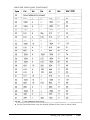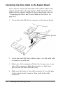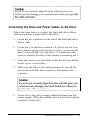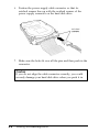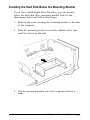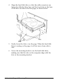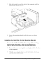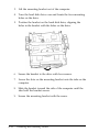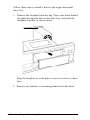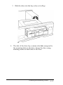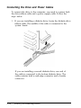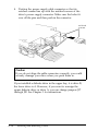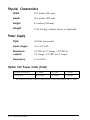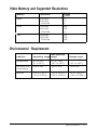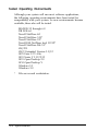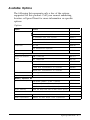
1
FCC COMPLIANCE STATEMENT
FOR AMERICAN USERS
This equipment has been tested and found to comply with the limits for a class B digital
device, pursuant to Part 15 of the FCC Rules. These limits are designed to provide
reasonable protection against harmful interference in a residential installation. This
equipment generates, uses, and can radiate radio frequency energy and, if not installed
and used in accordance with the instructions, may cause harmful interference to radio and
television reception. However, there is no guarantee that interference will not occur in a
particular installation. If this equipment does cause interference to radio and television
reception, which can be determined by turning the equipment off and on, the user is
encouraged to try to correct the interference by one or more of the following measures:
Cl Reorient or relocate the receiving antenna
0 Increase the separation between the equipment and receiver
0 Connect the equipment into an outlet on a circuit different from that to which the
receiver is connected
R Consult an experienced radio/TV technician for help.
WARNING
The connection of a non-shielded equipment interface cable to this equipment will
invalidate the FCC Certification of this device and may cause interference levels that
exceed the limits established by the FCC for this equipment. It is the responsibility of the
user to obtain and use a shielded equipment interface cable with this device. If this
equipment has more than one interface connector, do not leave cables connected to unused
interfaces.
Changes or modifications not expressly approved by the manufacturer could void the
user’s authority to operate the equipment.
FOR CANADIAN USERS
This digital apparatus does not exceed the Class B limits for radio noise emissions from
digital apparatus as set out in the radio interference regulations of the Canadian
Department of Communications.
Le present appareil numerique n’emet pas de bruits radioelectriques d&passant les limites
applicables aux appareils numeriques de Classe B prescrites dans le reglement sur le
brouillage radioelectrique edict6 par le Minis&e des Communications du Canada.
®
EPSON
EL 3S/33
User’s Guide
@
This manual is printed on recycled paper and is 100% recyclable.
IMPORTANT NOTICE
DISCLAIMER OF WARRANTY
Epson America makes no representations or warranties, either express or implied, by or
with respect to anything in this manual, and shall not be liable for any implied warranties
of merchantability and fitness for a particular purpose or for any indirect, special, or
consequential damages. Some states do not allow the exclusion of incidental or
consequential damages, so this exclusion may not apply to you.
COPYRIGHT NOTICE
All rights reserved. No part of this publication may be reproduced, stored in a retrieval
system, or transmitted, in any form or by any means, electronic, mechanical,
photocopying, recording, or otherwise, without the prior written permission of Epson
America, Inc. No patent liability is assumed with respect to the use of information
contained herein. Nor is any liability assumed for damages resulting from the use of the
information contained herein. Further, this publication and features described herein are
subject to change without notice.
TRADEMARKS
Epson is a registered trademark of Seiko Epson Corporation.
General notice: Other product names used herein are for identification purposes only and
may be trademarks of their respective companies.
Copyright 0 1993 by Epson America, Inc.
Torrance, California, USA
ii
400220801
Revised 7/93
Important Safety Instructions
1.
Read all of these instructions and save them for later reference.
2.
Follow all warnings and instructions marked on the computer.
3.
Unplug the computer from the wall outlet before cleaning. Use a
damp cloth for cleaning; do not use liquid or aerosol cleaners.
4.
Do not spill liquid of any kind on the computer.
5.
Do not place the computer on an unstable cart, stand, or table.
6.
Slots and openings in the cabinet and the back or bottom are
provided for ventilation; do not block or cover these openings.
Do not place the computer near or over a radiator or heat
register.
7.
Operate the computer using the type of power source indicated
on its label.
8.
If you plan to operate the computer in Germany, observe the
following safety precaution:
To provide adequate short-circuit protection and over-current
protection for this computer, the building installation must
be protected by a 16 Amp circuit breaker.
Beim AnschluB des Computers an die Netzversorgung muiJ
sichergestellt werden, dal3 die Gebtiudeinstallation mit einem
16 A ijberstromschutzschalter abgesichert ist.
9.
Connect all equipment to properly grounded (earthed) power
outlets. If you are unable to insert the plug into an outlet, contact
your electrician to replace your outlet. Avoid using outlets on
the same circuit as photocopiers or air control systems that
regularly switch on and off.
10 Do not allow the computer’s power cord to become damaged or
frayed.
iii
11. If you use an extension cord with the computer, make sure the
total of the ampere ratings of the devices plugged into the
extension cord does not exceed the ampere rating for the
extension cord. Also, make sure the total of all products plugged
into the wall outlet does not exceed 15 amperes.
12. Do not insert objects of any kind into this product through the
cabinet slots.
13. Except as specifically explained in this User’s Guide, do not
attempt to service the computer yourself. Refer all servicing to
qualified service personnel.
14. Unplug the computer from the wall outlet and refer servicing to
qualified service personnel under the following conditions:
A. When the power cord or plug is damaged.
B. If liquid has entered the computer.
C. If the computer does not operate normally when the operating
instructions are followed. Adjust only those controls that are
covered by the operating instructions. Improper adjustment
of other controls may result in damage and often requires
extensive work by a qualified technician to restore the
computer to normal operation.
D. If the computer has been dropped or the cabinet has been
damaged.
E. If the computer exhibits a distinct change in performance.
iv
Instructions Importantes de S&wit6
1.
Lire completement les instructions qui suivent et les conserver
pour references futures.
2.
Bien suivre tous les avertissements et les instructions indiques sur
l’ordinateur.
3.
Debrancher l’ordinateur de toute sortie murale avant le nettoyage.
Utiliser un chiffon humide; ne jamais utiliser un nettoyeur
liquide ou une bonbonne aerosol.
4.
Ne jamais renverser un liquide d’aucune sorte sur l’ordinateur.
5.
Ne pas placer l’ordinateur sur un chariot, un support, ou une table
instable.
6.
Les events dans les meubles, a l’arriere et en dessous sont congus
pour l’aeration; on ne doit jamais les bloquer. Ne pas placer
l’ordinateur pres d’une source de chaleur directe.
7.
Le fonctionnement de l’ordinateur doit s’effectuer conformement
au type de source d’alimentation indiquee sur l’etiquette.
8.
Lorsqu’on desire utiliser l’ordinateur en Allemagne, on doit
observer les normes securitaires qui suivent:
Afin d’assurer une protection adequate g l’ordinateur contre
les court-circuits et le survoltage, l/installation de l/edifice
doit comprendre un disjoncteur de 16 amp.
9.
On doit brancher tout l’equipement dans une sortie reliee a la
masse. Lorsqu’il est impossible d’inserer la fiche dans la prise, on
doit retenir les services d’un electricien ou remplacer la prise. Ne
jamais utiliser une prise sur le m@me circuit qu’un appareil a
photocopie ou un systeme de controle d/aeration avec
commutation marche-arret.
10. S’assurer que le cordon d’alimentation de l’ordinateur n’est pas
effrite.
V
11. Dans le cas ou on utilise un cordon de rallonge avec l’ordinateur,
on doit s’assurer que la valeur totale d’amperes branches dans le
cordon n’excede en aucun temps les amperes du cordon de
rallonge. La quantite totale des appareils branches dans la prise
murale ne doit jamais exceder 15 amperes.
12. Ne jamais inserer un objet de quelque sorte que ce soit dans les
cavites de cet appareil.
13. Sauf tel que specifib dans la notice d’utilisation, on ne doit jamais
tenter d’effectuer une reparation de l’ordinateur. On doit referer
le service de cet appareil a un technicien qualifie.
14. Debrancher l’ordinateur de la prise murale et confier le service au
personnel de service qualifie selon les conditions qui suivent:
A. Lorsque le cordon d’alimentation ou la prise sont
endommages.
B. Lorsqu’un liquide s’est infiltre dans l’ordinateur.
C. Lorsque l’ordinateur refuse de fonctionner normalement
m@me en suivant les instructions. N’ajuster que les
commandes qui sont enumerees dans les instructions de
fonctionnement. Tout ajustement inadequat de tout autre
controle peut provoquer un dommage et souvent necessiter
des reparations elaborees par un technicien qualifie afin de
remettre l’appareil en service.
D. Lorsqu’on a echappe l’ordinateur ou que l’on a endommage le
boitier.
E. Lorsque l’ordinateur demontre un changement note au niveau
de sa performance.
vi
Contents
Introduction
VGA Utilities . . . . . . .
Optional Equipment . .
Memory . . . . . . .
Drives . . . . . . . .
Math Coprocessor .
How to Use This Manual
. . . . . . . . . . . . . . . . . . . . . .
. . . . . . . . . . . . . . . . . . . . . .
. . . . . . . . . . . . . . . . . . . . . .
. . . . . . . . . . . . . . . . . . . . . .
. . . . . . . . . . . . . . . . . . . . . .
. . . . . . . . . . . . . . . . . . . . . .
2
2
2
2
3
3
Chapter 1 Setting Up Your System
Getting Started . . . . . . . . . . . . . . . . . . . . . . . . . . . .
Choosing a Location . . . . . . . . . . . . . . . . . . . . . .
Unpacking Your Computer . . . . . . . . . . . . . . . . .
Connecting the Computer . . . . . . . . . . . . . . . . . . . . .
Connecting a Keyboard . . . . . . . . . . . . . . . . . . . .
Connecting a Mouse . . . . . . . . . . . . . . . . . . . . . .
Connecting a Monitor . . . . . . . . . . . . . . . . . . . . .
Connecting a Printer or Other Device . . . . . . . . . . . .
Using the Parallel Port . . . . . . . . . . . . . . . . . . . .
Using the Serial Ports . . . . . . . . . . . . . . . . . . . . .
Connecting the Power Cord . . . . . . . . . . . . . . . . .
Turning On the Computer . . . . . . . . . . . . . . . . . .
Running the SETUP Program . . . . . . . . . . . . . . . . . . .
Starting the SETUP Program . . . . . . . . . . . . . . . . .
Displaying System Information . . . . . . . . . . . . . . .
Setting the Date and Time . . . . . . . . . . . . . . . . . .
Setting the Diskette Drive(s) . . . . . . . . . . . . . . . . .
Setting the Hard Disk Drive(s) . . . . . . . . . . . . . . . .
Checking System Memory . . . . . . . . . . . . . . . . . .
Setting the Video Display Type . . . . . . . . . . . . . . .
Setting Keyboard Options . . . . . . . . . . . . . . . . . .
Setting the Processor Speed . . . . . . . . . . . . . . . . . .
Setting Chip Set Feature Control Options . . . . . . . . .
Exiting the SETUP Program . . . . . . . . . . . . . . . . .
Post-SETUP Procedures . . . . . . . . . . . . . . . . . . . . . .
1-1
1-1
1-2
1-3
1-4
1-4
1-4
1-5
1-5
1-6
1-6
1-7
1-8
1-8
1-10
1-10
1-11
1-11
1-15
1-15
1-16
1-16
1-17
1-18
1-18
vii
Chapter 2 Using Your Computer
. . . . . 2-1
Turning On the Computer . . . . . . . . . . . . . . . .
Turning Off the Computer . . . . . . . . . . . . . . . .
Inserting and Removing Disks . . . . . . . . . . . . .
Stopping a Command or Program . . . . . . . . . . .
Resetting the Computer . . . . . . . . . . . . . . . . .
Changing the Processor Speed . . . . . . . . . . . . .
.
.
.
.
.
.
.
.
.
.
.
.
.
.
.
.
.
.
.
.
.
.
.
.
.
2-3
2-4
2-5
2-5
2-6
Chapter 3 Installing and Removing Options
Removing and Replacing the Cover .
Locating the Internal Components . .
Changing the Jumper Settings . . . .
Setting the Jumpers . . . . . . . .
Installing Memory Modules (SIMMs)
Inserting SIMMs . . . . . . . . . .
Removing SIMMs . . . . . . . . .
Installing an Option Card . . . . . . .
Removing an Option Card . . . . . . .
Adding Video Memory . . . . . . . .
Installing the Math Coprocessor . . .
Post-installationl Procedures . . . . . .
. . . . . . . . . . . . . . 3-2
.
.
.
.
.
.
.
.
.
.
.
.
.
.
.
.
.
.
.
.
.
.
.
.
.
.
.
.
.
.
.
.
.
.
.
.
.
.
.
.
.
.
.
.
.
.
.
.
.
.
.
.
.
.
.
.
.
.
.
.
.
.
.
.
.
.
.
.
.
.
.
.
.
.
.
.
.
.
.
.
.
.
.
.
.
.
.
.
.
.
.
.
.
.
.
.
.
.
.
.
.
.
.
.
.
.
.
.
.
.
.
.
.
.
.
.
.
.
.
.
.
.
.
.
.
.
.
.
.
.
.
.
.
.
.
.
.
.
.
.
.
.
.
.
.
.
.
.
.
.
.
.
.
.
3-5
3-6
3-8
3-9
3-10
3-12
3-13
3-16
3-16
3-19
3-20
Chapter 4 Installing and Removing Drives
Installing a Hard Disk Drive in the Internal Drive Bay . . . . . 4-2
Removing the Mounting Frames . . . . . . . . . . . . . . . 4-3
Connecting the Hard Disk Drive Cable . . . . . . . . . . . . 4-3
Connecting the Drive Cable to the System Board . . . . . . 4-4
Connecting the Drive and Power Cables to the Drive . . . 4-5
Installing the Hard Disk Below the Mounting Bracket . . . 4-7
Installing the Hard Disk On the Mounting Bracket . . . . . 4-9
Removing a Hard Disk Drive From the Internal Drive Bay . . . 4-11
Installing a Drive in the Upper Horizontal Drive Bay . . . . . . 4-11
Connecting the Drive and Power Cables . . . . . . . . . . . 4-14
Removing a Drive from the Upper Drive Bay . . . . . . . . . . . 4-17
Post-installation Procedures . . . . . . . . . . . . . . . . . . . . . 4-17
viii
Chapter 5 Installing Video Drivers
Installing the Drivers . .
Lotus 1-2-3 or Symphony
Microsoft Windows . . .
Microsoft Word . . . . .
Quattro Pro . . . . . . . .
WordPerfect . . . . . . .
.
.
.
.
.
.
.
.
.
.
.
.
.
.
.
.
.
.
. . . . . . . . . . . . . . . . . . .
. . . . . . . . . . . . . . . . . . .
. . . . . . . . . . . . . . . . . . .
. . . . . . . . . . . . . . . . . . .
. . . . . . . . . . . . . . . . . . .
. . . . . . . . . . . . . . . . . . .
5-2
5-3
5-4
5-5
5-6
5-7
Chapter 6 Troubleshooting
Identifying Your System . . . . . . . . . . . . . . . . . . . . . .
The Computer Will Not Start . . . . . . . . . . . . . . . . . . .
The Computer Does Not Respond . . . . . . . . . . . . . . . .
Keyboard Problems . . . . . . . . . . . . . . . . . . . . . . . . .
Monitor Problems . . . . . . . . . . . . . . . . . . . . . . . . . .
Diskette Problems . . . . . . . . . . . . . . . . . . . . . . . . . .
Diskette Drive Problems . . . . . . . . . . . . . . . . . . . . . .
Hard Disk Drive Problems . . . . . . . . . . . . . . . . . . . . .
Software Problems . . . . . . . . . . . . . . . . . . . . . . . . .
Printer Problems . . . . . . . . . . . . . . . . . . . . . . . . . . .
Option Card Problems . . . . . . . . . . . . . . . . . . . . . . .
Memory Module Problems . . . . . . . . . . . . . . . . . . . . .
Controller Problems . . . . . . . . . . . . . . . . . . . . . . . . .
Mouse Problems . . . . . . . . . . . . . . . . . . . . . . . . . . .
6-1
6-2
6-3
6-4
6-4
6-6
6-7
6-7
6-8
6-9
6-9
6-10
6-11
6-11
Appendix A Specifications
CPU and Memory . . . . . . . . . . . . . . . . . . . . . . . . . .
Controllers . . . . . . . . . . . . . . . . . . . . . . . . . . . . . .
Interfaces . . . . . . . . . . . . . . . . . . . . . . . . . . . . . . .
Physical Characteristics . . . . . . . . . . . . . . . . . . . . . . .
Power Supply . . . . . . . . . . . . . . . . . . . . . . . . . . . . .
Option Slot Power Limits (Total) . . . . . . . . . . . . . . . . . .
Video Memory and Supported Resolutions . . . . . . . . . . .
Environmental Requirements . . . . . . . . . . . . . . . . . . .
Tested Operating Environments . . . . . . . . . . . . . . . . . .
Available Options . . . . . . . . . . . . . . . . . . . . . . . . . .
A-1
A-2
A-2
A-4
A-4
A-4
A-5
A-5
A-6
A-7
Index
ix
Introduction
Your new Epson® EL 3S/33 computer is a high-performance
system offering flexibility and expandability in a compact
design. It provides the following features:
386SX, 33 MHz microprocessor
2MB or 4MB of internal memory, expandable to 16MB
System and video BIOS shadow RAM
256KB of on-board video memory, expandable to 512KB or
1024KB
Built-in VGA port
Two built-in serial ports, one built-in parallel port, and one
built-in game port
Built-in PS/2 compatible keyboard port
Three 16-bit full-length and two 8-bit half-length ISA option
slots
Support for up to three mass storage devices.
The shadow RAM feature allows your system to speed up
processing by moving the system and video BIOS into the RAM
area of memory.
Using the built-in interfaces, you can connect most of your
peripheral devices directly to the computer so you do not have
to install option cards. You can use the option slots to enhance
your system with extra functions such as a modem card, a
network controller card, or additional interface ports.
Introduction 1
The VGA controller supports standard resolutions up to
640 x 480 in 16 colors and extended resolutions up to 1024 x 768
in 4 colors (interlaced or non-interlaced). With 512KB video
memory, the controller supports resolutions up to 1024 x 768 in
16 colors; with 1024KB, it supports the same resolutions in up
to 256 colors.
VGA Utilities
Your computer comes with special VGA drivers and utilities
for use with the integrated VGA interface. With these utilities,
you can take advantage of the extended VGA features such as
high resolutions and 132-column text mode when you run
popular application programs.
Optional Equipment
You can easily upgrade your computer by installing additional
memory and a wide variety of options as described in
Chapters 3 and 4.
Memory
By adding 256KB, 1MB, and 4MB SIMMs (single inline memory
modules) to the main system board, you can expand the
computer’s memory up to 16MB.
Drives
Your system can support up to three internal mass storage
devices, including hard disk drives, diskette drives, a tape
drive, or a CD-ROM drive. As your storage needs expand, you
can install additional drives.
2
Introduction
Math Coprocessor
You may want to install an 80387SX, 33 MHz coprocessor. This
optional math coprocessor allows your computer to perform
mathematical functions faster.
How to Use This Manual
This manual contains the information you need to get the best
results from your computer. You do not have to read
everything in this book; check the following summary.
Chapter 1 provides simple instructions for setting up your
system and connecting peripheral devices such as the monitor
and printer. It also describes running the SETUP program to
define your computer’s configuration.
Chapter 2 covers general operating procedures, such as turning
the computer on and off, resetting the computer, and changing
the processor speed.
Chapter 3 describes how to remove and replace the computer’s
cover, change jumper settings, and install optional equipment
such as option cards and memory modules.
Chapter 4 explains how to install and remove disk drives.
Chapter 5 describes how to install VGA drivers and utilities.
Chapter 6 contains troubleshooting tips.
Appendix A lists the specifications of your computer, the
software that has been tested on your system, and options
available for your system.
At the end of this manual you’ll find an Index.
Introduction 3
Chapter 1
Setting Up Your System
This chapter briefly describes the operations you will use to set
up your computer. It includes the following information:
Q Getting started
Q Connecting the computer
Q Running the SETUP program
Ci Post-SETUP procedures.
Getting Started
Follow the instructions below for choosing a location for your
new system, unpacking your system, and setting up your
computer.
Choosing a Location
When you select a place to set up your system, choose a safe,
convenient location that provides the following:
Ct
A flat, hard surface. Surfaces like beds and carpets attract
static electricity, which can erase data on your disks,
damage the computer’s circuitry, and prevent proper
ventilation.
Cl
Good air circulation. Leave several inches of space around
the computer so air can move freely.
Setting Up Your System
1-2
LI
Moderate environmental conditions. Select a cool, dry area
and protect your computer from extremes in temperature,
humidity, dust, and smoke. Avoid direct sunlight or other
sources of heat.
Q No electromagnetic interference. Do not place your system
too close to any electrical device, such as a telephone or
television, which generates an electromagnetic field.
CI
Appropriate power source. Connect all your equipment
with the appropriate power cords for the power source in
your area.
Unpacking Your Computer
When you unpack your system components, make sure you
have these items:
computer
po
co
diskettes
manual
Q
keyboard
Your system also includes a serial mouse and may come with
the operating system and software already installed on a hard
disk drive.
1-2
Setting Up Your System
If you purchased any optional equipment that goes inside the
computer-such as option cards, memory modules, a hard
disk, or a diskette drive-you should install these devices
before you connect your computer. See Chapters 3 and 4 for
instructions.
Connecting the Computer
Use the illustration below to locate the ports on the back of
your system as you connect the keyboard, monitor, printer, and
other devices.
monitor cable
AC outlet
COM1
COM2 PARALLEL
Setting Up Your System
GAME
1-3
Connecting a Keyboard
To connect a keyboard, hold the cable connector so the arrow
on the connector faces up. Insert it into the port marked K/B.
Connecting a Mouse
Your system came with a serial mouse that connects to either of
the computer’s built-in serial ports. To connect the mouse, insert
the connector into one of the ports marked COM1 and COM2.
When you install the drivers for your mouse, make sure you
identify the port to which you connected it. See the README file
on the diskette that came with your mouse for more information.
Connecting a Monitor
The way you connect your monitor to the computer depends
on the type of monitor you have. If you have a VGA monitor
(or a multifrequency monitor with an analog connector), you
can connect it to the computer’s built-in VGA port as described
below. If you are connecting your monitor to an adapter card,
see Chapter 3.
1-4
1.
Place your monitor on top of or near the computer. Turn the
monitor and computer around so the backs are facing you.
2.
There should be two cables provided with your monitor: the
monitor cable (to connect it to the computer) and the power
cable (to connect it to the power source). On most monitors,
the monitor cable is permanently attached to the monitor. If
your monitor does not have an attached cable, connect the
cable to it now.
3.
Examine the connector on the monitor cable and line it up
with the VGA port on the computer. Then insert the
connector into the port.
Setting Up Your System
Caution
To avoid damaging the connector, be careful not to bend
the pins when you insert it.
4.
If the connector has retaining screws, tighten them.
5.
Plug the monitor power cord into the monitor’s power inlet.
6.
Plug the other end of the power cord into an appropriate
grounded electrical outlet or into the power outlet on the
back of the CPU.
Caution
If you plug the monitor’s power cord into the back of your
computer, make sure the monitor’s power requirements do
not exceed 1 Amp.
Connecting a Printer of Other Device
Your computer has one parallel and two serial ports. To
connect a printer or other peripheral device, follow the
appropriate instructions below.
Using the Parallel Port
Follow these steps to connect a parallel printer to your
computer:
1.
Place the printer next to the computer so that the backs are
facing you.
2.
Align the connector end of the printer cable with the
PARALLEL port and plug it in. If the connector has retaining
screws, tighten them.
Setting Up Your System
1-5
3.
Connect the other end of the cable to the printer. To secure
the cable, squeeze the clips at each side of the printer port
and push them into place.
4.
Plug the printer’s power cord into an appropriate grounded
electrical outlet.
Using the Serial Ports
If you have a printer, a modem, or a mouse with a serial
interface, you can connect it to one of the serial (RS-232C) ports
on the back of the computer. Make sure you have a cable
compatible with a DB-9P connector.
To connect a serial device, insert the connector into one of the
ports marked COM1 and COM2. If you are connecting only one
serial device, use the COM1 port.
Connecting the Power Cord
Follow these steps to connect the power cord:
1.
Plug the power cord into the AC power inlet on the back
panel.
Warning
To avoid an electric shock, be sure to plug the cord into
the computer before plugging it into the wall outlet.
2.
1-6
Plug the other end of the power cord into an appropriate
grounded electrical outlet.
Setting Up Your System
Turning On the Computer
After you set up your system, you are ready to turn on the
power. Follow these steps:
1.
Turn your computer around so the front panel faces you.
Place your monitor, printer, and other devices in a
convenient arrangement.
2.
If there is a protective card in the diskette drive, remove it
now.
3.
Turn on the monitor, printer, and any other devices
connected to the computer.
4.
Turn on the computer by pressing the power button on the
right side of the front panel.
The screen displays a count of the system memory, and then
the computer performs its power-on diagnostics, which are
a series of checks that make sure everything is working
correctly.
5.
If necessary, use the controls on your monitor to adjust the
brightness and contrast until you can easily see the
characters on the screen.
If your system is configured to automatically load a program
(such as Microsoft Windows or a word processing
program), you see the first menu or screen display of that
program. If not, you may see the operating system prompt,
such as C:\> or A:\>.
If there is no operating system installed on your computer,
you see an error message. Ignore the message for now; once
you install the operating system, you will not see this message.
Now follow the instructions in the next section to configure
your system using the SETUP program.
Setting Up Your System
1-7
Running the SETUP Program
You need to run SETUP the first time you use your computer.
Even if your system was configured for you, you may still need
to set the date and time, and if your system came unconfigured,
you need to define how it is set up. (You also may need to run
SETUP again later if you change your configuration.)
SETUP is stored in the computer’s ROM BIOS, so you can run it
any time. SETUP lets you verify or change the following:
Current date and time
Type of diskette drive(s) and hard disk drive(s)
System memory
Type of video display adapter
Keyboard options
Processor speed
Shadow options
Processor chip features.
The configuration information is stored in an area of memory
called CMOS RAM. This memory is backed up by a battery, so
it is not erased when you turn off or reset the computer.
Starting the SETUP Program
You can run SETUP whenever you see the operating system
command prompt, such as:
C:\> or A:\>
To start SETUP, hold down Ctrl and Alt, then press S.
1-8
Setting Up Your System
Also, whenever you start your computer, if the system detects
an error in your system configuration, you will see the
following message:
Press the F1 key to continue, F2
setup utility
to run the
Press F2 to run the SETUP program to correct your
configuration.
The table below lists the keys you can use to perform SETUP
operations.
SETUP function keys
Key
Function
Moves the cursor to the next or previous modifiable
option
f-
Changes the values in the field
PgDn PgUp
Displays the next or the previous menu
F1
Displays a help screen describing the option currently
selected
F4
From the exit menu, saves the changes you have
made and restarts your computer
F5
From the exit menu, supplies the factory default
values for all SETUP options
F6
From the exit menu, leaves the SETUP program
without saving any changes
Esc
Displays the exit menu
Whenever you are in the SETUP program, the bottom of the
screen lists the keys you can press to perform specific functions.
Setting Up Your System
1-9
Displaying System Information
The SETUP program provides a system information screen
which lists the following:
Cl Processor type
Ll Coprocessor type (if one is installed)
Cl Reserved memory
Ll
BIOS version number
Cl
Addresses for video mode, serial ports, and printer ports.
To see this information, press F2 from either of the SETUP
screens.
Setting the Date and Time
The real-time clock in your computer continuously tracks the
date and time-even when the computer is turned off. Once
you set the date and time using SETUP, you should not need to
change them, unless you adjust the time for daylight savings or
other seasonal adjustments. (The computer automatically
changes the date for leap years.)
Use ?, J, t or + to move the cursor to the value you want to
change. Then press + or - until you see the value you want.
1-10
Setting Up Your System
Setting the Diskette Drive(s)
On your system, diskette drive A is the 3.5-inch high-density
drive installed in the lower drive bay on your system. You may
also have another drive of a different size or capacity; this is
drive B. Check the settings for both drives and correct them if
necessary.
Note
If you add a diskette drive and want to reassign the top
drive as drive A, you must change jumpers J17 through J20,
as described in Chapter 3. Then run SETUP to reassign drive
types.
Setting the Hard Disk Drive(s)
The SETUP program lets you select the type of hard disk
drive(s) installed in your computer. If your system was
configured for you, the hard disk drive type has been preset.
To set the hard disk drive type, follow these guidelines:
Ll
If your system does not have a hard disk, select
Not Installed for Hard Disk 1 and Hard Disk 2.
Q
If your computer came with an Epson-installed hard disk
drive, you need to define your own drive type. For more
information, see “Defining your own drive type” on
page 1-14.
Ll If you have installed another type of hard disk drive, you
need to select the drive type number that matches your
drive.
Setting Up Your System
1-11
Hard disk drive types
The table below lists standard hard disk drives. Check this table
and your drive documentation to find the correct type number.
If none of the types listed matches your drive, see page 1-14.
Hard disk drive types
1 Type
1
Cyl
1 1
1
306
Hd
/
4
1
Pre
1
128
/
/
LZ
305
I
Sec
I
17
I
I
Size*(MB)
10
2
615
4
300
615
17
20
3
615
6
300
615
17
30
4
940
8
512
940
17
62
5
940
6
512
940
17
46
6
615
4
-1
615
17
20
7
462
8
256
511
17
30
8
733
5
-1
733
17
30
9
900
15
-1
901
17
112
10
820
3
-1
820
17
20
11
855
5
-1
855
17
35
12
855
7
-1
855
17
49
1 13
/
306
I
8
I
128
1
319
/
17
/
20
14
733
7
-1
733
17
42
16
612
4
0
663
17
20
17
977
5
300
977
17
40
18
977
7
-1
977
17
56
19
1-12
/
I
1024
1
7
1 20
1733
15
21
733
7
22
733
23
306
/
512
1300
I
1023
1 17
/
59
1732
117
130
300
732
17
42
5
300
733
17
30
4
0
336
17
10
Setting Up Your System
I
I
I
I
Hard disk drive types (continued)
Actual formatted size may be slightly different than size on drive label.
Setting Up Your System
1-23
Defining your own drive type
If the parameters for your hard disk (listed in its
documentation) do not match any of the types listed in the table
above, you can define your own type. Follow these steps:
1.
Move your cursor to Hard Disk 1 or 2 and press + or until you see drive type 48 or type 49.
2.
Press + to move the cursor to the Cyl field.
3.
Type the appropriate cylinder value for your hard disk. The
documentation that came with your hard disk drive will
provide the appropriate information.
4.
Continue pressing + to move the cursor to the next field and
type in the appropriate values.
If you are installing Epson-supplied drives, use the information
in the following table to define your drive type.
Epson-supplied hard disk drive types
l
Actual formatted size may be slightly different than size on drive label.
Note
If you are going to install NetWare 286, version 2.2, you
cannot assign a user-defined drive type for your drive
without installing two IDE drivers. You can obtain these
drivers (IDE.DSK and IDE.OBJ) by downloading IDE286.ZIP
from CompuServe®Alternatively, you can select one of the
pre-defined hard disk drive types that most closely matches
the drive you are installing.
1-14
Setting Up Your System
Checking System Memory
Your computer comes with 2MB or 4MB of random access
memory (RAM) on SIMMs. DOS and application programs that
run under DOS use the first 640KB of memory. You can use the
memory above 1MB as extended memory.
When you boot your system, the system BIOS detects the type
of RAM and updates the base memory size and the extended
memory size automatically. You see the memory configuration
displayed on this SETUP screen.
Setting the Video Display Type
The Video Card option lets you define the type of adapter
you are using for your primary display. If you connected your
monitor to the computer’s built-in VGA port, select EGA/VGA.
If you installed an optional video card, follow the guidelines
below to select the correct adapter type.
Video display type options
*
Select
If
EGA/VGA
You connected your monitor to the built-in VGA port or
you installed a VGA or enhanced graphics adapter (EGA)
card
CGA40*
You installed an optional color graphics adapter set to
40-column color graphics adapter (CGA) mode
CGA80*
You installed a CGA or a multi-mode graphics adapter
(MGA) attached to a color monitor
MONO*
You installed a monochrome display adapter or an MGA
attached to a monochrome monitor
For these options, you must change jumpers J36 and J37 on the system
board to the OFF position.
Setting Up Your System
1-15
Note
If you are installing a monochrome monitor, you also need
to set jumper J11 on the main system board to position 2-3.
See Chapter 3 for more information on setting jumpers.
Setting Keyboard Options
Two options in the SETUP program allow you to control
keyboard settings. The Keyboard option allows you to disable
the built-in keyboard connector if you are using an optional
connector.
The NumLock on at boot option determines the initial state
of the num lock function when you turn on or reset your
system. When num lock is off, the keypad controls cursor
movement. If num lock is on, the keypad types numbers.
Select YES to set the num lock function on when the system
starts.
Setting the Processor Speed
The CPU Speed option sets the processor speed to fast or
slow. At fast speed, your processor operates at its fastest speed,
33 MHz. At the slow speed setting, the processor operates at
8 MHz to provide compatibility with older application
programs.
Note
The Cyrix cache option is not available on this system.
1-16
Setting Up Your System
Setting Chip Set Feature Control Options
The second screen of the SETUP program contains the options
related to the features on your system board. Press PgUp or
PgDn to display this screen.
Relocating memory
The Relocate Memory option relocates the memory between
A0000h to BFFFFh and D0000h to EFFFFh for use as extended
memory. If you enable shadowing, however, relocation is
automatically disabled.
Shadow RAM options
Your computer can access RAM (random access memory) faster
than ROM (read only memory).
Two shadow features (Shadow BIOS ROM and Shadow Video
ROM) allow your system to copy the contents of its system and/or
video ROM into RAM so it can perform certain operations faster.
You can also shadow 32KB or 64KB of memory that starts at the
indicated addresses to RAM. If you enable these options, you
cannot use the Relocate Memory feature.
Additional options
Two additional chipset feature options allow you to slow down
your system in case you need compatibility with slower option
cards or diskette drives.
If you enable the ISA 1 wait state option, the system
inserts one wait state in a 16-bit ISA cycle rather than providing
the fastest processing at zero wait states.
The Slow Refresh option, when enabled, improves system
performance because it shortens the time needed for each
refresh cycle.
Setting Up Your System
1-17
Exiting the SETUP Program
When you leave the SETUP program, you can save your
settings and reboot your system, or exit SETUP without saving
your settings. You can also return all values to the factory
defaults.
To leave the SETUP program, press Esc from any SETUP
screen. From the SETUP exit menu, press these keys to perform
the following functions:
Esc
Returns to the SETUP utility
F4
Saves the changes you have made to your configuration
and restarts your computer
F5
Supplies the factory default values for all SETUP options
F6
Exits the SETUP utility and returns to the system prompt
without saving any changes.
Post-SETUP Procedures
After you run SETUP for the first time, you may need to install
the operating system on your computer. See your operating
system manual for instructions.
Also, install any software you plan to use. See your application
program manuals for instructions.
You may also want to install the optional extended video
drivers for some of your application programs. See Chapter 5
for more information.
1-18
Setting Up Your System
Chapter 2
Using Your Computer
This chapter briefly describes the following operations:
Ll
Turning the computer on and off
Li
Inserting and removing diskettes
Cl
Stopping a command or program
Ll Resetting the computer
tl
Changing the processor speed.
Turning On the Computer
Before you turn on your computer, check the following safety
rules to avoid accidentally damaging your computer or injuring
yourself:
Et
Do not connect or disconnect any peripheral device cables
(including the keyboard or a mouse) or power cables when
the computer’s power is on.
Ll Never turn off or reset your computer while a disk drive
light is on. This can destroy data stored on the disk.
Lt
Always wait at least 20 seconds after you turn off the
power before you turn it on again. This prevents possible
damage to the computer’s electrical circuitry.
D
Do not leave a beverage near your system. Spilled liquid
can damage the circuitry of your equipment.
Using Your Computer
2-1
Follow these steps to turn on your system:
1. Turn on the monitor, printer, and any other peripheral
devices connected to the computer.
2.
If you do not have a hard disk with an operating system
loaded on it, insert your main operating system diskette in
drive A.
3.
To turn on the computer, press the power button located on
the right side of the front panel, as shown below.
hard disk or
diskette drive bay
I
power
button
reset
button
hard disk
access light
power light
speed
(TURBO) light
I
diskette drive
The power indicator lights up. After a few seconds, the
computer displays a count of its system memory, and then
performs its power-on diagnostics. This is a series of checks the
computer runs each time you turn it on to make sure
everything is working correctly.
2-2
Using Your Computer
When the system has successfully completed its diagnostics,
DOS prompts you to verify the correct date and time. If they
are correct, press Enter. Otherwise, enter the current date and
time. If your system is configured to automatically start
Microsoft Windows or has a different operating system, you
may not see this prompt.
What happens next depends on how your computer is set up.
If your system is configured to automatically load a program
(such as Microsoft Windows or a word processing program),
you see the first menu or screen display of that program. If not,
you may see the operating system prompt, such as c : \ > or
A: \>.
Turning Off the Computer
Whenever you turn off your system, follow these steps:
1. Save your data and exit any application program you are
using.
2.
Check the hard disk drive light and the diskette drive light(s)
to make sure they are not on. Do not turn off the computer
if a drive light is on, because you can damage the drive or
lose data.
3.
Remove any diskette(s) from the diskette drive(s).
4.
Press the power button to turn off the computer and then
turn off the monitor, printer, and any other peripheral
devices.
Using Your Computer
2-3
Inserting and Removing Disks
To insert a diskette into a 3.5-inch drive, hold the diskette with
the label facing up and the metal shutter leading into the drive,
as shown in the following illustration. Slide the diskette into the
drive until it clicks into place.
release button
metal shutter
To insert a diskette into a 5.25-inch drive, hold the diskette with
the label facing up and the read/write slot leading into the
drive.
When you want to remove the diskette, make sure the drive
light is off; then press the release button or turn the latch.
Remove the diskette and store it properly.
Caution
Never remove a diskette or reset or turn off the computer
while a diskette drive light is on. You could lose data. Also,
remove all diskettes before you turn off the computer.
2-4
Using Your Computer
Stopping a Command or Program
You may sometimes need to stop a command or program while
it is running. If you have entered a DOS or application program
command that you want to stop, try one of the following:
Q Press Pause
Q
Hold down Ctrl and press C
Ll
Hold down Ctrl and press Break.
If these methods do not work, you may need to reset the
computer as described below. Do not turn off the computer to
exit a program or stop a command unless you have to, because
the computer erases any data you did not save.
Resetting the Computer
Occasionally, you may want to clear the computer’s current
settings or its memory without turning it off. You can do this
by resetting the computer.
For example, if an error occurs and the computer does not
respond to your keyboard entries, you can reset it to reload
your operating system and try again. However, resetting erases
any data in memory that you have not saved; so reset only if
necessary.
Caution
Do not reset the computer to exit a program. Some programs
classify and store new data when you exit them in the
normal manner. If you reset the computer without properly
exiting a program, you may lose data.
Using Your Computer
2-5
To reset the computer, the operating system must be either on
the hard disk or on a diskette in drive A; so if you do not have a
hard disk, insert the system diskette in drive A. Press the RESET
button located on the front left side of your computer. If you
are using DOS, you can also hold down Ctrl and Alt and press
Del. The screen displays nothing for a moment and then the
computer should reload your operating system.
If resetting the computer does not correct the problem, you
probably need to turn it off and on again. Remove any
diskette(s) from the diskette drive(s). Turn off the computer
and wait 20 seconds. If you do not have a hard disk, insert the
system diskette in drive A. Then turn on the computer.
Changing the Processor Speed
Your computer’s processor can operate at two speeds: high
speed (33 MHz) or low speed (8 MHz). The low speed is
available to provide compatibility with older application
programs.
When your computer is operating at high speed, the TURBO
light on the front panel is on. When the computer is operating
at low speed, the light is off.
You should use high speed for almost everything you do
because your programs will work faster. However, certain
application programs have specific timing requirements and
can run only at the slower speed. See your software manual to
determine if this is the case.
2-6
Using Your Computer
Some copy-protected programs require the computer to run at
low speed while accessing the program on a diskette. These
programs also usually require you to leave a key disk-the
diskette that contains the copy protection-in the diskette
drive. If you use a copy-protected program, you can change the
speed to low to access the diskette and return it to high speed
when you are finished.
You can change the processor speed temporarily by entering
one of the following commands from the numeric keypad on
your keyboard:
LI
To select low speed, press Ctrl Alt -. (Hold down the Ctrl
key and the Alt key simultaneously and then press the - key
on the numeric keypad.) The speed light turns off.
Ll To select high speed, hold down the Ctrl and Alt keys and
press + on the numeric keypad. The speed light comes on.
Note
You can use the commands listed above while you are
running a program. However, if the program uses one of
these commands for another function, you cannot use it to
change the processor speed. You can, however, change the
processor speed through the SETUP program.
The speed setting remains in effect until you do the following:
Cl
Reset your computer
U
Turn off your computer
tl
Change the speed with another keyboard command
tl
Change the speed setting in the SETUP program.
Using Your Computer
2-7
Chapter 3
Installing and Removing Options
You can enhance the performance of your computer by adding
optional equipment such as memory modules, option cards, or
a math coprocessor.
Memory modules-also called SIMMs (single inline memory
modules)-allow you to increase the amount of memory in
your computer.
An option card is a circuit board you install in your computer
to add a particular function, such as a modem or an additional
interface port.
The math coprocessor can be installed on the system board to
enhance numeric-intensive operations for software that
supports the coprocessor.
This chapter first describes how to remove your computer’s
cover to install options and how to replace the cover when you
are finished. It then describes the following:
Q Locating the internal components
Q Changing the jumper settings
Ci
Installing and removing memory modules (SIMMs)
D
Installing and removing option cards
tl Adding video memory
CI
Installing the math coprocessor.
Installing and Removing Options
3-1
Caution
Never install options or change jumper settings with the
computer turned on or the power cord connected to the
computer.
Once you have installed your option, see “Post-installation
Procedures” on page 3-20.
Removing and Replacing the Cover
You need to remove the computer’s cover to install any of the
options described in this chapter or to install or remove a disk
drive (as described in Chapter 4).
Follow these steps to remove the cover:
3-2
1.
Turn off the computer and then any peripheral devices
(including the monitor and printer).
2.
Disconnect the computer’s power cable from the electrical
outlet and from the back panel. Also disconnect any cables
that are connected to the computer, including the keyboard
cable.
3.
If the monitor is on top of the computer, lift it off and set it
to one side.
4.
Turn the computer around so the back panel is facing you.
Installing and Removing Options
5.
Remove the three screws securing the back panel, as shown
below.
i
6.
Grasp the sides of the cover and lift it straight up, as shown
below:
Installing and Removing Options
3-3
7.
Set the cover aside.
8.
Ground yourself to the computer by touching the metal
surface of the back panel.
Warning
Be sure to ground yourself by touching the back panel of the
computer every time you remove the cover. If you are not
properly grounded, you could generate an electric shock that
could damage a component when you touch it.
When you are ready to replace the computer’s cover, follow
these steps:
3-4
1.
Make sure all the internal components are installed
properly.
2.
Check all cable connections, especially those that might have
been loosened during your work.
3.
Make sure all cables are out of the way so they do not catch
on the cover.
4.
Insert the front of the cover between the front bezel and the
chassis of the computer and guide it straight down.
5.
Replace the three cover retaining screws.
6.
Reconnect the computer to the monitor, printer, keyboard,
and any other peripheral devices you have. Then reconnect
the power cable to the back of the computer and to an
electrical outlet.
Installing and Removing Options
Locating the Internal Components
As you follow the instructions in this chapter, refer to the
following illustration to locate the different components inside
your computer.
J36,
option
card
connector
power
coprocessor
J1-J10
<
system
- board
J15 -
- SlMMs
video
memory
<
J17-J20 ’
J25, J27
/
‘c
\
\
\
mounting bracket
\
drive bays
Installing and Removing Options
3-5
Changing the Jumper Settings
The main system board in your computer has a number of
jumpers which control certain functions. These jumpers are
preset at the factory to default positions; however, you can use
the information in the following tables to change their function,
if necessary:
Port jumper settings
Jumper
number
Jumper
setting
Function
J8
1-2*
2-3
Enables COM1 serial port
Disables COM1 serial port
J10
1-2*
2-3
Assigns COM1 serial port as COM1
Assigns COM1 serial port as COM3**
J2
1-2*
2-3
Enables COM2 serial port
Disables COM2 serial port
J3
1-2*
2-3
Assigns COM2 serial port as COM2
Assigns COM2 serial port as COM4**
J7
1-2*
2-3
Enables parallel port
Disables parallel port
J9
1-2*
2-3
Assigns parallel port as LPT1
Assigns parallel port as LPT2**
J4
1-2*
2-3
Enables game port
Disables game port
* Factory setting
l
* DOS automatically reassigns parallel and serial ports. Check your DOS
manual for more information.
Drive assignment jumper settings
Drive assignment
J17
J18
J19
J20
Upper drive is A
2-3
2-3
2-3
2-3
Lower drive is A
1-2*
1-2*
1-2*
1-2*
* Factory setting
3-6
Installing and Removing Options
Diskette drive con troller jumper settings
Jumper
number
Jumper
setting
Function
J27
1-2*
2-3
Enables diskette drive controller
Disables diskette drive controller
* Factory setting
Hard disk drive con troller jumper settings
Hard disk controller
J25
J22**
Enable
1-2*
On*
Disable
2-3
Off
* Factory setting
** Two-pin jumper
Display adapter jumper settings
Jumper
number
Jumper
setting
Function
J11
1-2‘
2-3
Color VGA display adapter
Monochrome display adapter
J15**
On
Off
Interlaced mode
Non-interlaced mode
* Factory setting
** Two-pin jumper
Built-in VGA jumper settings
1 Built-in VGA
1 J36**
Enable
~~ r dn*
Disable
Off
1 J37**
I
On*
I
Off
I
* Factory setting
** Two-pin jumper
Note
To use an external display adapter in an expansion slot, you
must disable the built-in VGA adapter.
Installing and Removing Options
3-7
Setting the Jumpers
If you need to change any jumper settings, follow these steps:
1.
Refer to the illustration on page 3-5 to locate the jumpers.
2.
If there are any option cards installed in your computer, you
need to remove them to access the jumpers. See page 3-16.
3.
A jumper’s setting is determined by where the jumper is
placed on the pins. A two-pin jumper either connects both
pins (on) or sits on just one of the pins (off). For three-pin
jumpers, the jumper connects pin 1 and the middle pin
(position 1-2) or pin 3 and the middle pin (position 2-3), as
shown below.
1
1 - 2
2 - 3
To move a jumper from one position to the other, use
needle-nose pliers or tweezers to pull it off its pins and
gently move it to the desired position.
Caution
Be careful not to bend the jumper pins or damage any
surrounding components on the main system board.
4.
3-8
Replace any option cards you removed. See page 3-13 for
instructions.
Installing and Removing Options
Installing Memory Modules (SlMMs)
Your computer comes with 2MB or 4MB on SIMMs. By
installing additional memory modules, you can increase the
amount of memory in your computer up to 16MB.
There are eight SIMM sockets on the main system board, and
each can contain one memory module. You can install 256KB,
1MB, and 4MB SIMMs.
The following table shows the possible SIMM configurations;
do not install memory in any other configuration. The label on
the system board for each SIMM socket (RAM1 through RAM8)
identifies the bank of sockets where you should install SIMMs.
SlMM configurations
Installing and Removing Options
3-9
Before you install SIMMs, check the following guidelines to
ensure that they will work properly:
LI
Use only 30-pin, fast-page mode SIMMs that operate at an
access speed of 70ns (nanoseconds) or faster. Be sure all the
SIMMs operate at the same speed.
Q Use the correct SIMM configuration to add the amount of
memory you want. See the table above.
Inserting SIMMs
Follow these steps to install SIMMs:
3-10
1.
Refer to the illustration on page 3-5 to locate the SIMM
sockets near the front of the computer.
2.
Remove any option cards that may be blocking your access
to the SIMM sockets. (See page 3-16 for instructions.)
Installing and Removing Options
3.
Position the first SIMM at an angle over the first empty socket
in the bank you are filling, as shown below. The components
on the SIMM should face the inside of the computer.
4. Push the SIMM into the socket until it is seated firmly in the
slot. Then tilt it upright, as shown above, guiding the hole
at each end of the SIMM over the retaining post at each end
of the SIMM socket. If it does not go in smoothly, do not
force it; pull it all the way out and try again.
5.
Repeat steps 3 and 4 for each additional SIMM.
6.
Replace any option cards you removed. (See page 3-13 for
instructions.)
Installing and Removing Options
3-11
Removing SlMMs
If you need to remove SIMMs from your computer (to install
different ones, for example), follow the steps below:
3-12
1.
Remove any option cards that may be blocking your access
to the SIMM sockets. (See page 3-16 for instructions.)
2.
Use your fingers or a small screwdriver to carefully pull
away the metal tabs that secure the SIMM at each end, as
shown below. As you pull away the tabs, the SIMM falls to
the side. Remove it from the socket.
3.
If necessary, follow the same procedure to remove the other
SIMMs.
4.
Replace any option cards you removed, as described below.
Installing and Removing Options
Installing an Option Card
This section explains how to install option cards in your
computer. Your computer has three 16-bit full-length slots and
two B-bit half-length slots to accommodate a total of five option
cards.
Usually it does not matter which slot an option card occupies as
long as the card fits in the slot. For example, you can place
some B-bit cards in a 16-bit slot. However, you cannot install a
16-bit card in an B-bit slot.
Caution
Make sure the power requirements for the option cards you
install do not exceed the power supply limitations. See your
option card manual(s) for the power requirements. Then
check Appendix A for the option slot power limits. Note that
older option cards that require -5 volts are not supported.
Before you install an option card, see if you need to change any
jumper settings on the system board. For example, if you install
a video card, you may need to change jumpers J11, J15, or J36
and J37. See page 3-6 for more information on jumpers.
Refer to the illustration below and follow these steps to install
an option card:
1. If you are using a 16-bit option slot, go on to step 2.
If you are using an B-bit slot near the power supply, you need
to remove the power supply before you can remove the
metal slot cover.
Installing and Removing Options
3-13
Remove the two retaining screws securing the power supply
to the back of the computer and the third retaining screw
holding the power supply to the base of the computer. Be
careful not to disconnect any of the cables. Slide the power
supply out of the way.
3-14
2.
Remove the retaining screws securing the option slot cover
to the computer. (Keep the screw to secure the option card
to the computer.)
3.
Slide out the slot cover and set it aside. (Store it in a safe
place in case you remove the option card later.)
4.
Unpack the option card and adjust any switches or jumpers
on it, if necessary. (Check the option card instructions.)
When you handle the card, be careful not to touch any of
the components on the circuit board or the gold-edged
connectors. If you need to set it down before you install it,
place it gently on top of its original packing material with
the component side facing up. Keep the packing materials
in case you remove the card later.
Installing and Removing Options
5.
Hold the card along the top corners and guide it into the
connector, as shown below. (If you are installing a
full-length card, insert the front edge of the card into the
corresponding guide inside the computer’s front panel.)
Once the connectors reach the slot, push the card in firmly
(but carefully) to insert it fully. You should feel the card fit
into place. If it does not go in smoothly, do not force it; pull
the card all the way out and try again.
6.
Secure the end of the card to the computer with the retaining
screw.
Installing and Removing Options
3-15
Removing an Option Card
You may need to remove an option card installed in your
computer to access components on the main system board-to
change a jumper setting, for example. You may also want to
remove a card if you no longer need it. Follow these steps:
1.
Remove the retaining screw securing the option card to the
computer. Then pull the card straight out of the slot.
2.
Set the card aside with the component side facing up.
Adding Video Memory
Your computer comes with 256KB of video memory. You can
increase your video memory to either 512KB or 1024KB by
installing four or six video DRAM, 20-pin, 70ns or 80ns, 44256
DIP (Dual Inline Package) chips. This is useful for running
graphics-intensive applications or for supporting resolutions
up to 1024 x 768 on your monitor. See Appendix A for a table
identifying supported colors and resolutions for each amount
of video memory.
For the memory to work properly, you must install chips in the
following configuration (each bank contains two video memory
chips).
Video memory chip configuration
Bank 0
Bank 1
Bank 2
Bank 3
256KB*
Soldered
l
3-16
Total
memory
Soldered
Filled
Soldered
Filled
512KB
Filled
Standard video memory
Installing and Removing Options
Filled
1024KB
1.
Locate the memory chip sockets on the main system board,
shown on page 3-5.
Bank 0 (labeled U24 and U40) contains two chips soldered to
the system board, so you cannot add video memory in this
bank. Bank 1 (U25 and U41) contains the two sockets closest
to the soldered chips. Bank 2 (U32 and U46) is the two
middle sockets in each set of three and Bank 3 (U33 and U47)
contains the remaining two sockets.
2.
If there is an option card in your way, remove it. See page
3-16 for instructions.
Caution
To avoid generating static electricity and damaging the
memory chips, ground yourself by touching the metal
surface on the inside of the computer’s back panel. Then
remain as stationary as possible while you install them.
3.
Remove the memory chips from their package and inspect
each one. The pins should point inward at slightly less than
a 90 angle.
If any of the pins are bent, straighten them gently with your
fingers or with small tweezers to align them with the other
pins. Be careful when you do this; the pins are fragile and
can break off easily.
Installing and Removing Options
3-17
4.
Position one of the memory chips over the first socket as
shown below, aligning the pins on the chip with the holes
in the socket. Make sure the small notch on the end of the
chip is facing the outside of the computer.
5.
Gently press the chip halfway into the socket (to make sure
it is correctly aligned). If the chip goes in at an angle,
remove it with a chip puller or a small flat-head
screwdriver and try again.
6.
When the chip is properly positioned, push down firmly on
both ends of the chip to make sure it is well-seated.
7.
Repeat steps 4 through 6 for each of the remaining chips.
8.
Replace any option cards you removed. See page 3-13 for
instructions.
When you start your computer, it displays the video memory
briefly before it begins its memory test.
3-18
Installing and Removing Options
Installing the Math Coprocessor
You can enhance your system’s performance for some
applications by installing an Intel 80387SX, 33 MHz, 68-pin
PLCC type math coprocessor.
Follow these steps to install the math coprocessor:
1.
Locate the socket for the math coprocessor. See page 3-5.
2.
If there is an option card in your way, remove it. See page
3-16 for instructions.
Caution
Before you remove the math coprocessor from its
antistatic packaging, touch an unpainted metal surface
on the computer chassis. Do not touch the pins on the
coprocessor. Handle the coprocessor only by the edges
of its case.
3.
Remove the coprocessor from its package and inspect it. If
the pins appear bent, do not install the coprocessor.
Installing and Removing Options
3-19
4.
Position the coprocessor over the socket as shown below.
Align the notched corner of the coprocessor (marked with
a dot) over the corresponding comer in the socket.
notched ’
corner
Be sure to align the pins in the coprocessor directly over
the holes in the socket. If you insert the math coprocessor
in the wrong position, you could permanently damage it.
5.
Make sure the pins in the coprocessor are directly over the
holes in the socket. Then gently push the coprocessor
straight into the socket, pressing evenly on all sides.
6.
Replace any option cards you removed. See page 3-13.
Post-installation Procedures
After you install or remove options such as memory modules
or a math coprocessor, you must run SETUP to update the
computer’s configuration. See Chapter 1 for instructions.
Additionally, you may need to add some commands to your
configuration files. See your operating system manual and the
manual that came with your optional equipment.
3-20
Installing and Removing Options
Chapter 4
Installing and Removing Drives
This chapter describes how to install and remove optional
drives in your computer. You can use these instructions to
install a variety of devices, including hard disk drives, a
diskette drive, a tape drive, or a CD-ROM drive. Although your
drive may look different from the ones illustrated here, you
should be able to install it the same way.
Your computer can hold up to three mass storage devices. You
can install a hard disk drive in the internal hard disk drive bay.
In the upper horizontal bay, you can install a second hard disk
drive (if you have the right cable), a second diskette drive, a
tape drive, or a CD-ROM drive.
To install or remove a drive, first remove the computer’s cover
as described in Chapter 3. Then use the instructions below to
install a hard disk drive in the internal hard disk drive bay or
follow the instructions on page 4-11 to install any type of drive
in the upper horizontal bay.
If you are installing or removing a non-Epson drive, some of
the steps in this chapter may not apply; see the documentation
that came with your drive for more information.
Installing and Removing Drives
4-1
Installing a Hard Disk Drive in the Internal Drive Bay
Your computer may have a hard disk drive already installed
using the hard disk drive mounting bracket. If not, you can
install a l-inch (third-height), 3½-inch wide drive below the
mounting bracket or above it.
Here you will find steps for the following procedures:
tl
Removing the mounting frames from the hard disk drive
(if necessary)
Ll Connecting the hard disk drive cables
U
Installing the hard disk drive under the mounting bracket
(for third-height drives)
Cl
Installing the hard disk drive on the mounting bracket.
Note
Be sure to check the jumper settings on the drive before you
install a hard disk drive. Also, you will need to know the
number of cylinders, heads, sectors, etc. to select the correct
drive type in the SETUP program. See the documentation
that came with your drive for this information.
Before you can install a hard disk drive, you need to remove
any option cards that may be blocking your access to the hard
disk drive area. Once you have installed the drive, replace any
option cards you removed. See Chapter 3 for instructions.
4-2
Installing and Removing Drives
Removing the Mounting Frames
If there are mounting frames attached to your hard disk drive,
you need to remove them before you can install the drive.
Follow these steps:
1.
On your drive, there may be a plastic guiderail and metal
grounding plate attached to one of the mounting frames. If
so, remove the screws securing them to the mounting frame
and remove the guiderail and grounding plate.
plastic guiderail
metal
mounting frames
2.
Then remove the two screws securing each mounting frame
to the drive and remove the frames.
Connecting the Hard Disk Drive Cable
To connect the hard disk drive to the computer, you need to
connect two cables: the hard disk drive ribbon cable and a
power supply cable. You should connect these cables before
you secure the drive with the mounting bracket because you
will not be able to attach them once the bracket is in place.
Installing and Removing Drives
4-3
Connecting the Drive Cable to the System Board
If you need to connect the hard disk drive ribbon cable to the
system board, follow the steps below. (If the hard disk drive
ribbon cable is already attached to the system board, refer to
“Connecting the Drive and Power Cables to the Drive” on
page 4-5.)
1.
Locate the hard disk drive connector on the system board.
2.
Locate the hard disk drive ribbon cable; it is a flat cable with
a connector on each end.
3.
Select one of the connectors. Notice the two grooves in one
side of the connector. Align the connector so that these
grooves face the hard disk drive bay.
4. Make sure the holes in the cable connector fit over the pins
in the system board connector; then push in the cable
connector.
4-4
Installing and Removing Drives
If you do not correctly align the holes with the pins, you
could severely damage your system board when you push m
Connecting the Drive and Power Cables to the Drive
Follow the steps below to connect the hard disk drive ribbon
cable and a power supply cable to the drive:
1.
Locate the free connector on the end of the hard disk drive
ribbon cable.
2.
Locate pin 1 on the drive connector. If you do not see it on
the connector casing, turn the drive over so you can see the
drive’s circuit board. You will see a 1 or 2 printed on the
board to identify the side of the connector containing pin 1.
3.
Align the connector on the cable so that the red wire will be
closest to pin 1 on the drive.
4.
Make sure the holes in the cable connector fit over all the
pins in the hard disk drive connector; then push in the
connector.
5.
Locate one of the power supply cables that lead from the
power supply. (They have multi-colored wires and a plastic
connector on the end.)
Installing and Removing Drives
4-5
6.
Position the power supply cable connector so that its
notched comers line up with the notched comers of the
power supply connector on the hard disk drive.
notched
7.
Make sure the holes fit over all the pins and then push in the
connector.
Caution
If you do not align the cable connector correctly, you could
severely damage your hard disk drive when you push it in.
4-6
Installing and Removing Drives
Installing the Hard Disk Below the Mounting Bracket
If you have a third-height hard disk drive, you can install it
below the hard disk drive mounting bracket. Refer to the
illustrations below and follow these steps:
1.
Remove the screw securing the mounting bracket to the base
of the computer.
2.
Slide the mounting bracket toward the diskette drive bays
until the slots clear the tabs.
3.
Lift the mounting bracket out of the computer and set it
aside.
Installing and Removing Drives
4-7
4.
Align the hard disk drive so that the cable connectors are
facing the diskette drive bays and the four holes at the base
of the drive are above the four pegs, as shown below.
pegs
4-8
5.
Gently lower the drive over the pegs. When the hard disk
drive is resting on the pegs, it will not move from side to
side.
6.
Lower the mounting bracket over the hard disk drive,
making sure that the tabs on the computer align with the
slots in the mounting bracket.
Installing and Removing Drives
7.
Slide the bracket toward the side of the computer until the
tabs hold the bracket secure.
8.
Secure the mounting bracket with the screw, as shown
above.
Installing the Hard Disk On the Mounting Bracket
You can also install a hard disk drive on top of the mounting
bracket rather than under it. Refer to the illustration on
page 4-7 and the one below while following these steps:
1.
Remove the screw securing the mounting bracket to the base
of the computer.
2.
Slide the mounting bracket toward the diskette drive bays
until the slots clear the tabs.
Installing and Removing Drives
4-9
3.
Lift the mounting bracket out of the computer.
4. Turn the hard disk drive over and locate the four mounting
holes on the drive.
5.
Position the bracket on the hard disk drive, aligning the
holes in the bracket with the holes on the drive.
6.
Secure the bracket to the drive with four screws.
7.
Lower the slots on the mounting bracket onto the tabs on the
computer.
8. Slide the bracket toward the side of the computer until the
tabs hold the bracket secure.
9.
4-10
Secure the mounting bracket with the screw.
Installing and Removing Drives
Removing a Hard Disk Drive From the Internal
Drive Bay
To remove a hard disk drive, reverse the installation steps
outlined above. Then disconnect the hard disk drive ribbon
cable and the power supply cable from the back of the drive.
When you disconnect the cables, grasp the connectors and pull
them straight out so you do not bend the pins; do not pull on
the cables. Use the screw to again secure the hard disk drive
mounting bracket to the base of the computer.
Installing a Drive in the Upper Horizontal Drive Bay
Your system comes with a 3.25-inch diskette drive installed in
the lower horizontal drive bay. You can also install a diskette
drive, a CD-ROM, a tape drive, or a second hard disk drive in
the upper horizontal drive bay. If you install a second hard disk
drive in this bay, make sure you purchase the appropriate cable
to connect both drives to the hard disk drive connector.
Before you install a drive in the upper drive bay, remove the
cover. Once you have the drive installed, replace the cover,
following the instructions in Chapter 3.
Installing and Removing Drives
4-11
Follow these steps to install a drive in the upper horizontal
drive bay:
1.
Remove the faceplate from the bay. Place your hand behind
the plate through the hole in the drive bay, and push the
faceplate forward, as shown below.
Keep the faceplate in a safe place in case you remove a drive
later.
2.
4-12
Remove any brackets or mounting frames from the drive.
Installing and Removing Drives
3.
4.
Slide the drive into the bay as far as it will go.
The side of the drive bay contains slots that correspond to
the mounting holes in the drive. Secure the drive using
retaining screws in both sides of the drive.
Installing and Removing Drives
4-13
Connecting the Drive and Power Cables
To connect the drive to the computer, you need to connect both
the drive ribbon cable and a power supply cable. Follow the
steps below.
1.
If you are installing a diskette drive, locate the diskette drive
ribbon cable. The middle of the cable is connected to the
system board.
If you are installing a second diskette drive, one end of
the cable is connected to the bottom diskette drive. The
cable contains both a card-edge connector and a header
connector.
4-14
Installing and Removing Drives
If you are installing a hard disk drive in the upper
horizontal bay, make sure you use the proper hard disk
drive ribbon cable and connect the drive to the hard disk
drive connector. Also, if this is the second hard disk drive in
your system, make sure you set the jumpers on both hard
disk drives to indicate which is the master and which is the
slave drive.
2.
If the drive connector extending from the back of the drive
has gold contacts on both sides, use the card-edge
connector on the ribbon cable. Make sure you align the
key-way (the plastic divider) with the gap in the drive
connector.
If the drive connector contains a series of pins, use the
header connector. Identify pin 1 on the drive and align the
connector so that the red wire is at pin 1.
3.
Locate one of the power supply cables that lead from the
power supply. (They have multi-colored wires and a plastic
connector on the end.)
Installing and Removing Drives
4-15
4.
Position the power supply cable connector so that its
notched comers line up with the notched corners of the
drive’s power supply connector. Make sure the holes fit
over all the pins and then push in the connector.
notched
corners
Caution
If you do not align the cable connectors correctly, you could
severely damage your drive when you push them in.
If you installed a diskette drive in the upper bay, it is drive B;
the lower drive is A. However, if you want to reassign the
upper diskette drive as drive A, you can change jumpers J17
through J20. See Chapter 3 for instructions.
4-16
Installing and Removing Drives
Removing a Drive from the Upper Drive Bay
To remove a drive from the upper drive bay, follow these steps:
1.
Remove both the ribbon cable connector and the power
cable connector from the drive.
2.
Remove the screws securing the drive.
3.
Reach behind the drive and gently push it to the front of the
bay; then pull it out of the slot.
4.
Once you have removed the drive, replace the faceplate by
inserting one side of the plate, then gently guiding the other
side into place. You will hear it snap into place.
Post-installation Procedures
After you install or remove your drive(s) and replace the cover
on your computer, you need to run the SETUP program to
define the correct configuration for your newly-installed drive.
See Chapter 1 for instructions.
Installing and Removing Drives
4-17
Chapter 5
Installing Video Drivers
The Utility diskettes included with your system contain
enhanced VGA (video graphics array) drivers and utilities for
your computer’s built-in VGA adapter. This chapter describes
how to install and use these drivers and utilities.
Your computer’s built-in VGA adapter is compatible with IBM
VGA. The drivers and utilities described in this chapter work
with any VGA and compatible, multifrequency monitors that
use analog input.
Standard VGA monitors display resolutions up to 640 x 480,
and you do not need to install the drivers or utilities for your
system to operate properly with your application programs at
this resolution.
However, if you want to use resolutions over 640 x 480 or take
advantage of the following special features when using certain
application programs, you need to install the appropriate
drivers:
U
Enhanced graphic and text modes in 4, 16, and 256 colors
Cl
Resolutions up to 1024 x 768
Ll Extended text mode for 132-column text with 25, 30, 43, and
60 rows.
Your computer comes with 256KB of video memory installed
on the system board. You can upgrade the video memory to
either 512KB or 1MB by installing additional video memory
chips, allowing you to use higher resolutions and more colors.
See Chapter 3 for installation instructions.
Installing Video Drivers
5-1
This chapter describes installation procedures for the following
common applications:
Ll Lotus 1-2-3 and Symphony, version 2.x (see page 5-3)
0
Microsoft Windows, version 3.1 (see page 5-4)
0
Microsoft Word, version 5.0 (see page 5-5)
Cl
Quattro Pro, version 2.x (see page 5-6)
a
WordPerfect, version 5.1 (see page 5-7)
Your Utility diskettes contain VGA utilities and drivers for
additional applications. If you want to install these utilities or
an extended video driver for an application not listed above,
read the README files on your Utility diskettes. These files
will tell you what additional applications are supported and
will describe the VGA utilities.
Installing the Drivers
The information in this guide is organized alphabetically by
application program or operating environment. To install a
particular driver, turn to the page listed above for your
application or environment.
Note
Each of the VGA drivers is designed to work with a specific
version of software. Make sure the driver you select is
compatible with the version of software you are using, or
you may get unpredictable results.
5-2
Installing Video Drivers
Lotus 1-2-3 or Symphony
If you have not yet installed Lotus 1-2-3 or Symphony, follow
the instructions in your Lotus documentation to install it. Then
follow these steps to install the drivers:
1.
Insert Utility Diskette 1 in drive A.
2.
Type A : and press Enter to log onto drive A.
3.
Copy the drivers from the Utility Diskette 1 to the Lotus or
Symphony program directory on your hard disk.
If you are installing drivers for 1-2-3 to the C:\LOTUS
directory, type the following and press Enter:
SET123 C:\LOTUS
If you are installing drivers for Symphony to the
C:\SYMPHONY directory, type the following and press
Enter:
SETSYMPH C:\SYMPHONY
4.
Log onto your Lotus program directory.
5.
Type INSTALL and press Enter to run the installation
program.
6.
From the main menu, select Advanced options and press
Enter.
7.
Then select Add new drivers to library and press
Enter.
8.
When the program finishes adding drivers to the library,
select Modify current driver set and press Enter.
Installing Video Drivers
5-3
9.
Select Text display to modify the text mode or
Graphics display to modify the graphics resolution.
Then press Enter.
10. Select the TVGA driver you want to install from the
displayed list and press Enter.
11. Select Return to menu and press Enter.
12. At the Installation menu, select Save changes.
13. At the prompt, type the name you want to use for the driver
set and press Enter.
14. Exit the Install program.
15. When you start 1-2-3 or Symphony, type 123 or SYMPHONY,
followed by the name of the driver set you want to use, and
then press Enter.
Microsoft Windows
If you have not yet installed Windows 3.1, follow the
instructions in your Windows documentation to install it with
the standard VGA driver. Then follow these instructions to
install the new driver:
1. Log onto your Windows program directory.
5-4
2.
Type
3.
At the System Information screen, select Display and press
Enter.
4.
From the Display menu, select Other (Requires disk
provided by hardware manufacturer) and press
Enter.
SETUP
and press Enter.
Installing Video Drivers
5.
Insert the Utility Diskette 1 in drive A.
6.
Type the following path:
A:\WIN
7.
Select the driver you want to install.
8.
Follow the instructions on the screen to finish running
SETUP.
Note
All Windows driver files are compressed using Microsoft
COMPRESS. If you install the drivers to or from a network
server, you must expand all driver files by using Microsoft
EXPAND. See your Windows documentation for
instructions.
Microsoft Word
If you have not yet installed Word 5.0, follow the instructions in
your Word documentation to install it. Then follow these
instructions to install the appropriate driver:
1.
Log onto your Word program directory.
2.
Rename the driver file SCREEN.VID to the name
SCREEN.OLD.
3.
Insert the Utility Diskette 1 in drive A.
4.
Copy the SCREEN.VID file from the diskette to your Word
program directory. Type the following command and press
Enter to copy the file:
COPY A:\WORD\SCREEN.VID
Installing Video Drivers
5-5
5. Start your Word application.
6.
Press Esc to enter a command.
7. Press 0 to enter an Option command.
8.
Select Display Mode.
9.
Press F1 to list the display modes available. Choose one
of the following display modes to indicate the number of
rows for your display:
1
2
3
4
5
6
7
8
Text,
Text,
Text,
Text,
Text,
Text,
Text,
Text,
25
43
50
60
25
30
43
60
lines,
lines,
lines,
lines,
lines,
lines,
lines,
lines,
16
16
16
16
16
16
16
16
color
color
color
color
color*
color*
color*
color*
*These are 132-column modes and provide no mouse support.
Press 1 to see additional drivers.
Your Word application now uses the display mode you
selected.
Quattro Pro
If you have not yet installed your Quattro Pro application,
follow the instructions in the Quattro Pro documentation to
install it now. Then follow these steps to install the extended
VGA drivers for Quattro Pro:
1. Log onto your Quattro Pro directory.
2.
5-6
Insert the Utility Diskette 1 in drive A.
Installing Video Drivers
3.
Type the following command and press Enter to copy the
new display drivers to your Quattro Pro directory:
COPY A:\QPRO\VIDEO.RSC
4.
Start your Quattro Pro application.
5.
Type /O to select the Options menu.
6.
Type D to display the available display mode drivers.
7. Select Trident VGA.
8.
Select the extended text mode you want to use.
Your Quattro Pro application now uses the display mode you
selected.
WordPerfect
If you have not yet installed WordPerfect 5.1, follow the
instructions in your WordPerfect documentation to install it.
Then follow the instructions below to install the new drivers.
1.
Log onto the WordPerfect directory on your hard disk.
2.
Insert the Utility Diskette 1 in drive A.
3.
Copy the extended text and graphics drivers from the utility
disk to your WordPerfect directory by typing:
COPY A:\WP51\*.VRS
4.
Start your WordPerfect application.
5.
Press Shift F1 to display the Setup menu.
6.
Select Display.
Installing Video Drivers
5-7
7. Select Graphics Screen Type.
8. Choose Trident TVGA.
9. Select one of the extended graphics drivers. Choose from
800 x 600, 16 colors; 1023 x 768, 16 colors; and 786 x 1024,
16 colors.
10. Now select Text Screen Type.
11. Choose Trident VGA.
12. Select the resolution you want for your text driver.
13. Press F7 to exit. Your selection is saved and used for
displaying text as well as the print preview and graphics
functions of WordPerfect.
5-8
Installing Video Drivers
Chapter 6
Troubleshooting
If you have any problems as you set up and use your computer,
refer to this chapter. You can correct most problems by
adjusting a cable connection, repeating a software procedure, or
resetting the computer.
The troubleshooting suggestions in this chapter are organized
in general categories, such as “The computer will not start.”
Within each category, a more specific problem is described with
possible solutions.
If the suggestions here do not solve the problem, contact your
Epson dealer.
Identifying Your System
When you request technical assistance, be ready to provide the
serial number of your computer, its system BIOS version
number, its configuration (including the type of disk drives,
monitor, and option cards), and the names and version
numbers of any software programs you are using.
Troubleshooting 6-1
Use the following table to locate this information.
Location of system information
System information
Location
Serial number
On the back panel of the computer
Video BIOS version
On the screen during power-on diagnostics
System BIOS version
On SETUP System Information screen
System configuration
On SETUP screens
DOS version
In response to the DOS VER command
Software versions
In application banner screen; in “About”
application window; within application
documentation
The Computer Will Not Start
The power light is on, but the computer does not start.
Replace your main operating system diskette and turn on the
computer again.
Caution
If you turn off the computer, always wait at least 20 seconds
before turning it back on. This prevents damage to the
computer’s electrical circuitry.
The computer does not start and the power light is not lit.
Make sure the power cord is securely connected to both the AC
inlet on the back panel and an electrical outlet.
6-2 Troubleshooting
The power cord is securely connected, but the computer
still does not staff.
Check the electrical outlet for power. Turn off your computer
and unplug the power cord. Plug a lamp into the outlet and
turn it on.
You installed of removed system components, and now
your computer does not staff.
Check to make sure you have reconnected all the internal and
external cables correctly.
The Computer Does Not Respond
The computer locks up.
Wait a few moments; if your computer does not respond after a
reasonable length of time, turn it off, wait 20 seconds, and try
again.
You may have installed memory using SIMMs that work at the
wrong speed. You can try using the SETUP program to insert a
wait state (see Chapter 1) or you can install the correct SIMMs
(see Chapter 3).
You turned the computer off and on again, but it still does
not respond.
Try resetting the computer using the Ctrl Alt Del command.
Your computer suddenly stops operating.
You may have overloaded the power supply limitations. See
your option card manual(s) for the power requirements for
your option card(s). Then check Appendix A to see if you have
exceeded the option slot power limits.
Troubleshooting 6-3
Keyboard Problems
The screen displays a keyboard error message when you
turn on of reset the computer.
Make sure the keyboard is securely connected to the correct
port.
Nothing happens when you type on the keyboard.
See “The Computer Does Not Respond,” above.
The cursor keys on the numeric keypad do not work
properly.
If the Num Lock light in the upper right corner of the keyboard
is lit, press NumLock to turn off the function.
If you want to change the initial settings of the num lock
function, see “Setting the NumLock On at Boot” in Chapter 1.
Monitor Problems
There is no display on the screen.
Check that the monitor’s power switch is on and that its power
light is lit.
The power light is on, but you still do not see anything on
the screen.
Check the brightness and contrast controls.
If you still do not see anything on the screen, make sure you
connected your monitor to the computer securely.
6-4 Troubleshooting
If you installed a display adapter card, make sure your monitor
and display adapter match. Also check to see if the card’s
switches or jumpers and the jumpers on the system board are
set properly. See Chapter 3 for system board jumper
information.
If you are running an application program, see if you need to
set up the program for the type of monitor and display adapter
you have. Also make sure you are using the appropriate
monitor and display adapter for your software.
%;.,.,.,,.I
If your application program requires a monitor that supports
graphics but you have a monochrome monitor, the results
The power switch is on but the power light is not on.
Turn off the monitor’s power, wait five seconds, and turn it
back on.
If the light still does not come on, check the electrical outlet for
power. Turn off your monitor and unplug it from the outlet.
Then plug a lamp into the wall outlet and turn it on. If the light
turns on, your monitor may be faulty.
Troubleshooting 6-5
Diskette Problems
You see a diskette error message.
Reinsert the diskette, making sure you insert it all the way. If
the drive has a latch, turn it down to secure the diskette.
Also, check to see that you have inserted the right type of
diskette in the drive. For example, make sure you are not
inserting a high-density diskette in a double-density drive.
Reinserting the diskette does not solve the problem.
Insert the diskette in another diskette drive of the same type. If
you can read the diskette in a different drive, your drive may
be faulty.
The diskette is the right type, but you still see an error.
Check that the diskette is not write-protected, preventing the
drive from writing to the diskette.
Make sure the diskette is formatted. See your operating system
documentation for instructions on formatting diskettes.
You may have a defective diskette. Try copying the files from
the bad diskette to a new diskette.
Something is wrong with the data in the files.
If you are using DOS, use CHKDSK to repair the files. You may
also be able to use special utilities or diagnostics to solve this
problem.
6-6 Troubleshooting
Diskette Drive Problems
A newly-installed diskette drive is not working properly.
Make sure you have installed the drive correctly and check all
the cable connections.
You see a diskette drive error when you start your computer.
Run the SETUP program and configure your system for the
correct type of diskette drive.
The diskette drive is making loud or unusual noises.
Contact your dealer or service representative.
Hard Disk Drive Problems
A newly-installed hard disk drive is not working properly.
Make sure you have installed the drive correctly and check all
cable connections. Also, check the jumper settings on your
drive.
You see a hard disk drive error when you start your system.
Run SETUP and update your system configuration for the hard
disk drive. Make sure you selected the correct drive type.
Make sure the jumpers on the system board are set correctly.
See Chapter 3 for jumper information.
You are unable to store data on the hard disk drive.
Make sure you have partitioned and formatted the drive
correctly for your operating system. Use the procedures
provided in your operating system manual.
Troubleshooting 6-7
Also, make sure your hard disk drive has been physically
formatted by the manufacturer. If it has not been physically
formatted, use the format utility that came with the drive to
format it.
Note that a physical format is different from software-based
formatting commands, such as the DOS FORMAT command.
You have been using your hard disk drive successfully for
some time but notice a reduction in performance.
The data on the disk may have become fragmented. Back up all
your data and use a disk compaction utility to reorganize the
files on your disk.
If you cannot access data on your hard disk or you are seeing
read/write errors, the disk may have a physical problem.
Contact your dealer.
Software Problems
The application program does not start.
Check that you are following the correct procedure for starting
the program and that it is installed correctly. If you do not have
a hard disk, make sure the correct diskette is in the diskette
drive.
The application program is having trouble reading a key
disk.
You may be running an application that requires a slower
processor speed. See Chapter 2 for information on setting the
processor speed.
6-8 Troubleshooting
Your application has locked the computer, making if
unresponsive to keyboard commands.
Reset the computer and try again. If resetting the computer
does not help, turn it off, wait 20 seconds, then turn it on again.
Some software, like OS/2, Unix, or NetWare 3.11, needs a
minimum of 4MB to 8MB of RAM to work correctly. Check
your software documentation for the minimum memory
requirements. If necessary, add additional memory using the
instructions in Chapter 3.
Printer Problems
The printer does not work at all.
Check that the printer has power and is properly connected to
the computer. Also make sure your printer has paper in it.
The printer prints garbled information.
Check the printer manual for the printer’s correct DIP switch or
control panel settings.
Also, make sure you have the proper drivers installed for your
printer.
Option Card Problems
A new/y installed option card is not working correctly.
Make sure the option card is installed correctly and is
well-seated in its slot. Run the SETUP program to update your
computer’s configuration after you install the card. Also,
perform setup procedures for any software you are using with
the option card.
Troubleshooting 6-9
Also, see the documentation that came with the option card to
set any necessary DIP switches or jumpers on the card.
The main system board of your computer may also have some
jumpers that must be set for the option card to work properly.
See Chapter 3 for system jumper information.
Your system may need to operate at the slower processor speed
to access the device. Try reducing the processor speed (see
Chapter 2) or inserting a wait state through the SETUP
program (see Chapter 1).
You may have inserted an older option card that works at
-5 volts. Make sure you install option cards that meet the
system’s power requirements.
An external device connected to the option card is not
working correctly.
Make sure you are using the proper cable to connect the device
to the card.
Memory Module Problems
The memory count displayed by the power-on diagnostics
program is incorrect.
You may have installed the SIMMs incorrectly. They may be
the wrong type or speed, or they may not be inserted all the
way. See Chapter 3 for information on installing SIMMs.
6-10 Troubleshooting
Controller Problems
You see a controller error for the hard disk drive controller,
the video controller, or the I/O port controllers when you
start your system.
The indicated controller on your system board may be faulty.
If you have an option card with a controller that will work with
your device, you can install it and change the jumper settings
on the system board to disable the built-in controller. You can
then continue to use your system until it is convenient for you
to have it serviced.
Mouse Problems
Your mouse isn’t working properly or you see an auxiliary
device error message.
Make sure the mouse cable is securely connected to one of the
serial ports. Also make sure you installed the mouse driver
correctly and selected the right settings for the serial ports in
the SETUP program. See the documentation that came with
your mouse and Chapter 1 for instructions.
Troubleshooting
6-11
Appendix A
Specifications
CPU and Memory
32-bit CPU
Intel or AMD 80386SX, 33 MHz
microprocessor with 16-bit data bus
System speed
High and low speeds available; high speed
is 33 MHz, low speed is 8 MHz; speed
selection through SETUP program and
keyboard commands; zero wait state
memory access at high speed; wait states
of zero or one selectable through SETUP
Memory
2MB or 4MB RAM standard on SIMMs;
expandable to 16MB using 256KB, 1MB,
and 4MB SIMMs; SIMMs must be 30-pin,
fast-page mode type with 70ns or faster
access speed
ROM
64KB system BIOS, video BIOS, and
SETUP code located in EPROM on main
system board
Video RAM
256KB DRAM on main system board;
expandable to 512KB or 1024KB using
70ns or 80ns 44256 DIP chips
Shadow RAM
Supports shadowing of system and video
BIOS ROM into RAM
Math
coprocessor
Optional 80387SX, 33 MHz coprocessor
available
Specifications A-l
Clock/
calendar
Real-time clock, calendar, and CMOS
RAM socketed on main system board with
built-in battery backup
Controllers
Video
Trident VGA controller on main system
board; provides resolutions up to
1024 x 768 in 16 colors
Diskette
Controller on main system board supports
up to two diskette drives
Hard disk
Interface on main system board supports
up to two IDE hard disk drives with
built-in controllers
Interfaces
Monitor
VGA interface built into system board;
15-pin, D-shell connector
Parallel
One standard 8-bit parallel, uni-directional
interface built into main system board;
25-pin, D-shell connector
Serial
Two RS-232C, programmable,
asynchronous interfaces built into main
system board; 9-pin, D-shell connectors
Game
One 15-pin, D-shell connector
Keyboard
PS/2 compatible keyboard interface built
into main system board; num lock setting
selectable through SETUP; 6-pin, mini DIN
connector
A-2 Specifications
Option slots
Three 16-bit full-length and two B-bit
half-length I/O expansion slots, ISA
compatible, 8 MHz bus speed
Speaker
Internal
Mass storage
Two 3 1/2-inch wide drives (one internal
mount) and one 5 1/4-inch wide, half-height
drive
Diskette drives
3.5-inch diskette drive, 1.44MB
(high-density) storage capacity
5.25-inch diskette drive, 1.2MB
(high-density) storage capacity
3.5-inch diskette drive, 720KB
(double-density) storage capacity
5.25-inch diskette drive, 360KB
(double-density) storage capacity
Hard disk
drives
3 1/2-inch form factor hard disk drive(s), up
to half-height size; the first mounted
internally, and second mounted in the
horizontal drive bay
Other devices
Half-height tape drive, CD-ROM, or other
storage device; 5 1/4-inch or 3 1/2-inch with
mounting frames
Specifications A-3
Physical Characteristics
Width
15.6 inches (396 mm)
Depth
14.5 inches (368 mm)
Height
4.1 inches (104 mm)
Weight
15 lb (6.8 kg), without drives or keyboard
Power Supply
Type
65 Watt, fan-cooled
Input ranges
90 to 260 VAC
Maximum
outputs
+5 VDC at 7.5 Amps, +12 VDC at
2.0 Amps, -12 VDC at 0.3 Amps
Frequency
47 to 63 Hz
Option Slot Power Limits (Total)
*
Maximum current*
+5
For all slots
4.6 Amps
Volts
+ 12 Volts
- 12 Volts
1.8 Amps
0.3 Amps
This system does not support older option cards that may require -5 volts.
A-4 Specifications
Video Memory and Supported Resolutions
c
Memory
Resolutions
256KB
640x480
800x600
1024x768
16
16
4
512KB
640x480
800x600
1024x768
256
256
16
1MB
640x480
800x600
1024x768
256
256
256
Environmental Requirements
Condition
Non-operating
Operating range range
Storage range
Temperature
41° to 90°F
(5° to 32°C)
-4° to 140°F
(-20° to 60°C)
-4° to 140°F
(-20° to 60°C)
Humidity (noncondensing)
20% to 90%
10% to 90%
10% to 90%
Altitude
-330 to 9,900 ft
(-100 to 3.000 m)
-330 to 39,600 ft
(-100 to 12,000 m)
330 to 39,600 ft
(-100 to 12,000m)
Specifications A-5
Tested Operating Environments
Although your system will run most software applications,
the following operating environments have been tested for
compatibility with your system. As new environments become
available, these also will be tested.
MS-DOS 3.3 through 6.0
DR DOS 6.0
Novell NetWare 4.0
Novell NetWare 3.11*
Novell NetWare 2.2*
Novell-ELS NetWare level II 2.12*
Novell NetWare 386 3.1*
OS/22.1
OS/2 Extended Version 1.1/l.2
SCO Unix 3.2 V 4.0n
SCO Xenix V 1.1.2/2.3.3
SCO Open Desktop 2.0
SCO Open Desktop V
Windows 3.1
Windows 3.0
*
File server and workstation.
A-6 Specifications
Available Options
The following list represents only a few of the options
supported for this product. Call your nearest marketing
location or Epson Direct for more information on specific
options.
Options
Option
Product
Monitors
14” VGA monochrome monitor
Product code
A880611
I
i 14” VGA color monitor, 0.39 mm
A804321
14" Extended color VGA monitor
A804211
17” Professional Series monitor
A804241
20" Professional Series monitor
A804341
Keyboards
101 USA
A800181
Mouse
9-pin serial mouse
A880282
Additional diskette
drives
5.25” 1.2MB FDD
A811371
3.5” 1.44MB FDD
A811381
Hard disk drives
80MB HDD w/embedded AT controller
A812001
120MB HDD w/embedded AT controller
A811951
170MB HDD w/embedded AT controller
A880861
240MB HDD w/embedded AT controller
A811991
102 International keyboard
Mass storage devices
CD-ROM
Half-height CD-ROM
Tape backup drive
Epson 250MB tape backup unit
A811613
Memory expansion kits
System memory
Video memory
1MB SlMMs (256KB x 9,70ns. 4 pieces)
A808831
2MB SlMMs (1MB x 9,70ns. 2 pieces)
A808841
8MB SlMMs (4MB x 9,70ns. 2 pieces)
A808631
44256 DIP chips with 70ns or 80ns access speed
Other
Network cards
Standard network interface card
Math coprocessor
80387SX, 33 MHz. 68-pin. PLCC coprocessor
Specifications A-7
Options (continued)
Option
Product
Product code
Printers
?-pin
Epson LX-810, narrow carriage
1 C016231
ActionPrinter 2250, narrow carriage
I C100011
FX-870, narrow carriage
I
I
FX-1170, wide carriage
24-pin
DFX-5000, wide carriage
I C112001
DFX-8000, wide carriage
I
C030001
ActionPrinter 3250, narrow carriage
C092011
LQ-570. narrow carriage
C062001
LQ-860, narrow carriage
LQ-870, narrow carriage
C035031
1
C060021
LQ-1070. wide carriage
C063001
LQ-1170. wide carriage
C061021
LQ-2550, wide carriage
EPL-8000
L752
I
C09001
ActionLaser 1000
C108001
ActionLaser 1000 (2MB)
C108001-2
ActionLaser 1500
Inkjet
C094001
Stylus 800 Ink Jet Printer
I
C095001
I
1
j
1
I
C108101
I
C106001
/
Software
Microsoft Windows 3.1
Epson MS-DOS 5.0, 5.25” diskettes
1Epson MS-DOS 5.0. 3.5" diskettes
1 A807162
IA807172
MS-DOS 6.0, 3.5” diskettes
Epson OS/2. version 2.0
i A807062
DR DOS 6.0, 3.5" diskettes
1NetWare Lite 1.1, 3.5" diskettes
A-8 Specifications
1
A880382
I
1
Index
A
C
AC power inlet, 1-4, 1-6,6-2
Addresses, memory, 1-10, 1-17
Air circulation, 1-1
Altitude, A-5
Analog
connector, 1-4
VGA input, 5-1
Application program
copy protected, 2-7
display problems, 6-5
exiting, 2-3, 2-5
loading automatically, 2-3
problems, 6-8
requiring slow speed, 1-16, 2-6
stopping, 2-5
timing requirements, 2-6
VGA drivers, 5-1 -2
Cable
adjusting connection, 6-1
diskette drive, 4-14 -15, 4-17
hard disk drive, 4-2 -3, 4-11
key-way connector, 4-15
keyboard, 1-4
modem, 1-6
monitor, 1-4
mouse, 1-6
power supply, 4-3, 4-5, 4-14 -16
printer, 1-5
reconnecting, 6-3
red wire, 4-5, 4-15
serial device, 1-6
Calendar, A-2
Card
display adapter, 1-4, 1-15
modem, Intro-1
option, Intro-1 -3, 1-17, 3-1
problems, 6-9
protective, 1-7
video, 1-4, 1-15
Card-edge connector, 4-14 -15
CD-ROM, Intro-2, 4-1, 4-11
CGA (color graphics adapter), 1-15
Chassis, 3-4
Checking system memory, 1-15
Chip set feature control, 1-17
CHKDSK command, 6-6
Choosing a location, l-l
Clock, real-time, 1-10, A-2
CMOS RAM, 1-8, A-2
Color monitor, 1-15
Command prompt, 1-8, 1-18, 2-3
Compatibility, VGA driver, 5-2
Component, damaging, 3-4
Compressed VGA drivers, 5-5
Computer problems, 6-2
B
Back panel, 3-2
Banks
SIMM socket, 3-9
video memory, 3-16 -17
Base memory, 1-15
Battery, 1-8, A-2
Bay
diskette drive, 2-2, 3-5
internal hard disk drive, 4-1
upper horizontal, 4-1
Bezel, 3-4
BIOS, Intro-l, 1-8, 1-10, 1-15, 1-17,
6-2, A-1
Booting system, 1-9, 1-15, 1-18
Brackets, 4-12
Brightness, 1-7, 6-4
Button
diskette release, 2-4
power, 2-2
RESET, 2-2, 2-6
Index 1
Configuration
changing, 1-8 -9, 1-18
drive, 4-17
files, 3-20
SIMM, 3-9 -10
system, 6-1
Connecting
keyboard, 1-4
modem, 1-6
monitor, 1-4
mouse, 1-6
power cords, 1-5 -6, 2-1, 3-2, 3-4
printer, 1-5
Connector
analog, 1-4
card-edge, 4-14
hard disk drive, 4-4 -5
header, 4-14
keyboard, 1-4, 1-16
monitor, 1-4
power supply cable, 4-16
printer, 1-5
serial device, 1-6
Contrast, 1-7, 6-4
Control codes
CTRL ALT +, 2-7
CTRL ALT -, 2-7
CTRL ALT DEL, 2-6, 6-3
CTRL BREAK, 2-5
CTRL C, 2-5
Control panel settings, 6-9
Controller
diskette drive, A-2
hard disk drive, A-2
jumpers, 6-11
parallel port, A-2
problems, 6-11
VGA, A-2
Conventional memory, 1-15
Coprocessor
math, Intro-3, 3-1, 3-19-20, A-1
socket, 3-5
type, 1-10
2
Index
Cover
removing, 3-3
replacing, 3-4
CPU
specifications, A-1
speed, 1-16
CTRL ALT +, 2-7
CTRL ALT -, 2-7
CTRL ALT DEL, 2-6, 6-3
CTRL BREAK, 2-5
CTRL C, 2-5
Cursor, 1-9, 1-16, 6-4
Cylinder value, 1-14
D
Data
losing, 2-3-5
saving, 2-3
Date, setting, 1-10, 2-3
Daylight savings, 1-10
DB-9P connector, 1-6
Default settings, 1-18
Delay, ISA, 1-17
Depth, A-4
Diagnostics, power-on, 1-7, 2-2,
6-10
DIP switches, 6-10
Disk compaction utility, 6-8
Disk drive light, 2-1 -2, 2-4
Diskette
defective, 6-6
formatted, 6-6
inserting, 2-4
key, 2-7, 6-8
label, 2-4
problems, 6-6
removing, 2-34
type, 6-6
write-protected, 6-6
Diskette drive
assignment, 1-11, 3-6, 4-16
bay, 2-2, 3-5
cable, 4-14 -15, 4-17, 6-7
Diskette drive
caution, 4-16
configuration through SETUP,
4-17, 6-7
controller jumper, 3-7
errors, 6-7
faulty, 6-6
installing, 4-1 -18
jumpers, 3-6 -7, 4-16
latch, 2-4, 6-6
light, 2-1, 2-4
power cable, 4-14 -15, 4-17, 6-7
problems, 6-7
protective card, 1-7
reassigning drive A, 1-11, 3-6, 4-16
removing, 4-17
ribbon cable, 4-14 -15, 4-17, 6-7
type, 4-2
upper horizontal bay, 4-1
Display
modes, 5-6
option, 1-15
Display adapter
connecting, 1-4
defining, 1-15
jumper settings, 3-7, 6-5
DOS, 1-15, 6-2
DRAM video chips
installing, 3-16
type, 3-16, A-1
Drivers
printer, 6-9
video (VGA), Intro-2, 1-18, 5-1 -8
Drives, See Hard disk drive or
diskette drive
E
EGA (enhanced graphics adapter),
1-15
EGA/VGA, 1-15
Electric shock, 1-6, 3-4
Electrical
circuitry, 2-1, 6-2
outlet, 1-5 -6, 6-2 -3
Electromagnetic interference, 1-2
Environmental
conditions, 1-2
requirements, A-5
Errors
diskette drive, 6-7
hard disk drive, 6-7
keyboard, 6-4
operating system, 1-7
read/write, 6-8
Exit menu, SETUP, 1-18
Expanding VGA drivers, 5-5
Extended
memory, 1-15, 1-17
text mode, 5-1, 5-7
VGA, Intro-2, 1-18
video drivers, 5-2
External device problems, 6-10
F
Faceplate
removing, 4-12
replacing, 4-17
Factory default settings, 1-18
Fast processor speed, 1-16, 2-6-7,
A-l
Files, repairing, 6-6
Formatting
diskettes, 6-6
hard disk drive, 6-7-8
Frequency, power supply, A-4
Full-length option slots, A-3
Function keys, SETUP, 1-9
G
Game port, Intro-l, A-2
Game port jumpers, 3-6
Grounding plate, 4-3
Grounding yourself, 3-4, 3-17, 3-19
Guiderail, 4-3
Index
3
H
Half-length option slots, A-3
Hard disk drive
bays, 3-5
cable, 4-2 -3, 4-5 -6, 4-11, 4-14 -16
caution, 4-5-6
circuit board, 4-5
configuration through SETUP,
4-17
connecting cables, 4-3 -5
connector, 4-4, 4-6, 4-11
controller, A-2
cylinder value, 1-14
Epson-supplied, 1-11, 1-14
errors, 6-7
formatting, 6-7 -8
grounding plate, 4-3
guiderail, 4-3
installing, Intro-2, 4-1 -18
internal bay, 4-1
jumpers, 3-7, 4-2, 4-15, 6-7
light, 2-1 -2
master, 4-15
mounting bracket, 4-2 -3, 4-7, 4-9
mounting frames, 4-2-3
mounting holes, 4-10
number, 1-11
parameters, 1-14
physical format, 6-8
power cable, 4-2 -3, 4-5 -6, 4-11, 4-16
problems, 6-7
removing, 4-11, 4-17
ribbon cable, 4-2 -5, 4-11, 4-14 -15
setting, 1-11
slave, 4-15
type, 1-11 -13, 4-2
upper bay, 4-1
user-defined type, 1-13
Height, A4
Help screen, SETUP, 1-9
High processor speed, 1-16, 2-6 -7,
A-1
Humidity, A-5
4
Index
I
I/O
expansion slots, A-3
problems, 6-11
IDE controller, A-2
Indicator light
diskette drive, 2-4
hard disk drive, 2-2
monitor, 6-5
power, 2-2, 6-2, 6-4
speed, 2-2, 2-6
TURBO, 2-2, 2-6
Inlet, AC power, 1-4, 1-6,6-2
Input ranges, power supply, A-4
Installing operating system, 1-7,
1-18
Interface port, 3-1
Interference, electromagnetic, 1-2
Interlaced
mode jumper, 3-7
monitor, Intro-2
Internal components, 3-5
ISA wait state, 1-17, 6-10, A-1
J
Jumpers
changing settings, 3-6, 3-8
diskette drive assignment, 1-11,
3-6, 4-16
diskette drive controller, 3-7
display adapter, 3-7, 6-5
game port, 3-6
hard disk drive, 3-7, 4-2, 4-15, 6-7
interlaced mode, 3-7
location, 3-5
main system board, 3-5-6
option card(s), 3-13 -14, 6-10
port settings, 3-6
reassigning diskette drive, 1-11,
3-6, 4-16
three-pin, 3-8
two-pin, 3-8
Jumpers
VGA controller, 3-7
video card, 3-13, 6-5
K
K/B, 1-4
Key disk, 2-7, 6-8
Key-way, 4-15
Keyboard
checking connections, 6-4
connecting, 1-4
connector, 1-4, 1-16
num lock, 1-16, 6-4
option, 1-16
port, Intro-l, 1-4, A-2
problems, 6-4
processor speed command, 2-7,
A-1
PS/2 compatible, Intro-l, A-2
reconnecting, 3-4
Keypad, numeric, 1-16, 2-7, 6-4
Keys, SETUP function, 1-9
L
LAN card, Intro-l
Location, choosing, l-l
Lotus 1-2-3 VGA drivers, 5-3
Low processor speed, 1-16, 2-6 -7,
6-8, 6-10, A-1
Low-level format, 6-7-8
M
Main system board, See System
board
Mass storage, Intro-l-2, 4-1, A-3
Master hard disk drive, 4-15
Mathcoprocessor
installing, 3-1, 3-19
positioning, 3-20
type, Intro-3, 3-19, A-1
MDA (monochrome display
adapter), 1-15
Memory
addresses, 1-10, 1-17
base, 1-15
clearing, 2-5
CMOS RAM, 1-8, A-2
conventional, 1-15
count, 1-7,2-2
extended, 1-15, 1-17
installing, Intro-2, 3-9
insufficient, 6-9
modules, See SIMMs
problems, 6-10
RAM, Intro-l, 1-15, 1-17, A-l
relocate option, 1-17
removing, 3-12
reserved, 1-10
ROM, 1-8, 1-17, A-l
SIMMs, See SIMMs
size, 1-15
standard, A-1
system, Intro-l-2, 1-7-8,1-15,
1-17, A-l
video, Intro-l-2, 3-5, 3-16, A-1
Messages, error, 1-7, 6-4, 6-6 -8, 6-11
Metal shutter, 2-4
MGA (multi-mode graphics
adapter), 1-15
Microprocessor, 3-5, A-1
Modem, Intro-l, 1-6, 3-1
Monitor
assigning type, 1-15
brightness, 1-7, 6-4
cables, 1-4
connecting, 1-4
contrast, 1-7, 6-4
monochrome, 1-16, 3-7,6-5
multifrequency, 1-4,5-1
power cord, 1-4,6-5
power switch, 6-5
problems, 6-4
reconnecting, 3-4
turning off, 2-3, 3-2
Index
5
Monitor
turning on, 2-2
VGA port, 1-4, 1-15
Monochrome adapter jumper
settings, 3-7
Mounting bracket
identifying, 4-2
installing hard disk drive, 4-7,
4-9
securing, 4-3, 4-9
slots, 4-7
Mounting frames, removing, 4-2-3
Mounting holes, 4-13
Mouse, 1-4, 1-6,6-11
Multifrequency monitor, 1-4, 5-1
N
NetWare 286, 1-14
Non-interlaced
mode, jumper, 3-7
monitor, Intro-2
Non-operating range, A-5
Num lock, 1-16 ,6-4
Numeric
coprocessor, See Math
coprocessor
keypad, 1-16,2-7,6-4
0
Operating procedures, Intro-3
Operating range, A-5
Operating system
diskette, 2-2, 2-6, 6-2
errors, 1-7
installing, 1-7, 1-18
prompt, 1-8, 1-18, 2-3
reloading, 2-5-6
Option cards
8-bit, Intro-l
16-bit, Intro-l
connector board, 3-5
connectors, 3-14
DIP switches, 6-10
6
Index
Option cards
guides, 3-15
installing, Intro-2-3, 3-1, 3-13
jumpers, 3-13 -14, 6-10
power requirements, 3-13, 6-10
problems, 6-9
removing, 3-8, 3-16
Option slots
cover, 3-13
length, A-3
power limits, 3-13, 6-3, A-4
Optional equipment, 1-3, 3-1
Orientation dot, 3-20
Outlet, electrical, 1-5 -6, 6-2 -3
P
Parallel port
controller, A-2
jumpers, 3-6
Pause key, 2-5
Physical format, 6-8
Port
additional, Intro-l
game, Intro-l, A-2
jumper settings, 3-6
keyboard, Intro-l, 1-4, A-2
location, 1-3
parallel, Intro-l, 1-5, 3-6, A-2
RS-232C, 1-6, A-2
serial, Intro-l, 1-5, 3-6, A-2
VGA, Intro-l, 1-4, 1-15
Post-installation procedures, 3-20
Power
button, 1-7, 2-2
inlet, AC, 1-4, 1-6,6-2
light, 2-2, 6-2, 6-4
monitor switch, 6-4-5
Power cable
computer, 1-5, 2-1, 3-2 , 3-4
diskette drive, 4-14-16
hard disk drive, 4-2 -3, 4-5 -6, 4-11,
4-15-16
monitor, 1-4, 6-5
Power cord, 1-5 -6, 2-1, 3-2, 3-4
Power requirements
monitor, 1-5
option cards, 3-13, 6-10
Power supply
cables, 4-3, 4-5, 4-14 -15
frequency, A-4
input ranges, A-4
limitations, 3-13, 6-3
location, 3-5
maximum outputs, A-4
removing, 3-13
type, A-4
Power-on diagnostics, 1-7, 2-2, 6-10
Printer
checking connections, 6-9
drivers, 6-9
problems, 6-9
reconnecting, 3-4
turning off, 2-3, 3-2
turning on, 2-2
Processor speed
changing, 2-6-7, A-1
fast, 1-16, 2-6 -7, A-1
keyboard command, 2-7
problems, 6-8
SETUP, 1-16, 2-7
slow, 1-16, 2-6 -7, 6-8, 6-10, A-1
Processor type, 1-10
Prompt, 1-8, 1-18, 2-3
Q
Quattro Pro VGA drivers, 5-6
R
RAM, Intro-l, 1-15, 1-17, A-1
RAM, shadow, Intro-l, A-l
Read/write
errors, 6-8
slot, 2-4
Real-time clock, 1-10, A-2
Red wire, 4-5, 4-15
Refresh cycle time, 1-17
Relocate memory option, 1-17
Repairing files, 6-6
Reserved memory, 1-10
RESET button, 2-2, 2-6
Resetting the computer, Intro-3,
1-16, 2-5, 6-1
Resolutions, Intro-2, 5-1 -8, A-2
Ribbon cable
card-edge connector, 4-15
diskette drive, 4-14 -15, 4-17, 6-7
hard disk drive, 4-2 -5, 4-11,
4-14 -15
header connector, 4-15
ROM, 1-8, 1-17, A-1
RS-232C ports, 1-6, A-2
S
Safety precautions, 2-1, 3-2
Screws, 1-4 -5, 3-3, 4-9 -10
Serial number, 6-1 -2
Serial port
controller, A-2
jumpers, 3-6
Settings, clearing, 2-5
SETUP
assigning drive type, 4-2
changing processor speed, 1-16,
2-7, A-1
changing values, 1-10
drive configuration, 4-17
exit menu, 1-18
factory default settings, 1-18
function keys, 1-9
help screen, 1-9
inserting wait state, 6-10
num lock function, 1-16, 6-4
processor speed, 1-16, 2-7, A-1
saving settings, 1-18
starting, 1-8
Shadow
BIOS ROM, 1-17
RAM, Intro-l, A-l
video ROM, 1-17
Index
7
SIMMS
banks, 3-9
configuration, 1-15, 3-9 -10
incorrect type, 6-3
installing, Intro-2, 3-1, 3-9
location, 3-5
positioning, 3-11
removing, 3-12
sockets, 3-11
type, 3-10, A-l
Slave hard disk drive, 4-15
Slot cover, 3-13
Slots, option, Intro-l
Slow processor speed, 1-16, 2-6 -7,
6-8, 6-10, A-1
Slow refresh option, 1-17
Sockets
SIMM, 3-9, 3-11
video, 3-16
Software
installing, 1-18
problems, 6-8
version, 6-2
Speaker, A-3
Specifications, Intro-3, A-1 -8
Speed, See Processor speed
Speed light, 2-2, 2-6
Static electricity, l-l
Stopping a command or program,
2-5
Storage devices, Intro-1 -2
Symphony VGA drivers, 5-3
System
BIOS, 6-1 -2, A-1
board, 3-5 -6, 3-9, 3-13, 3-17, 4-4 -5
configuration, 6-1 -2
identifying, 6-1
specifications, A-1 -8
8
Index
T
Tape drive, Intro-2, 4-1, 4-11
Temperature, A-5
Three-pin jumper, 3-8
Time, setting, 1-10, 2-3
Timing requirements, 2-6
Trident, 5-7-8, A-2
Troubleshooting, Intro-3, 6-1-12
TURBO light, 2-2 ,2-6
Turning off computer, 2-3, 3-2
Turning on computer, 2-1
TVGA, 5-4, 5-8
Two-pin jumper, 3-8
U
User-defined drive type, 1-13
Utility
disk compaction, 6-8
diskettes, 5-1
VGA, Intro-2 -3, 5-1 -2
V
VGA
adapter jumper, 3-7
compressed drivers, 5-5
controller, Intro-2
driver compatibility, 5-2
drivers, Intro-3, 5-1-8
enhanced drivers, 5-1
IBM, 5-1
installing drivers, 1-18
interface, A-2
jumpers, 3-7
Lotus 1-2-3 drivers, 5-3
port, Intro-l, 1-4, 1-15
Quattro Pro drivers, 5-6
standard, 5-1
Symphony drivers, 5-3
utilities, Intro-2 -3, 5-1 -2
Windows drivers, 5-4-5
Word drivers, 5-5
WordPerfect drivers, 5-7
Video
BIOS, 6-2, A-1
card jumpers, 3-13, 6-5
chips, 3-16, A-1
controller, A-2
drivers, installing, 1-18, 5-1 -8
jumper settings on card, 6-5
modes, 5-1
resolutions, Intro-2, 5-1-8, A-2
ROM, 1-17
Video memory, 3-5
adding, 3-16
configuration, 3-16
displaying, 3-18
on system board, 5-1
sockets, 3-16
type, 3-16, A-l
W
Wait state, 1-17, 6-10, A-1
Weight, A-4
Width, A-4
Windows drivers, 5-4-5
Word, VGA drivers, 5-5
WordPerfect, VGA drivers, 5-7
Write-protection, 6-6
Z
Zero wait states, 1-17
Index
9
Epson America (USA)
Epson America, Inc.
20770 Madrona Avenue
Torrance, CA, 90509-2842
Tel: (310) 782-0770
Fax: (310) 782-5051
Epson Direct
P.O. Box 2858
20770 Madrona Avenue
Torrance, CA 90509-1111
Tel: (800) 374-7300
Epson America (International)
Epson Latin America
Miami, EL, U.S.A
Tel: (305) 265-0092
Fax: (305) 265-0097
Epson Mexico, S.A. De C.V.
Mexico, D.F., Mexico
Tel: (525) 395-9897
Fax: (525) 395-9499
Epson Argentina, S.A.
Buenos Aires, Argentina
Tel: (541) 322-7487
Fax: (541) 322-4637
Epson Do Brasil
Sgo Paulo, SP Brazil
Tel: (5511) 813-3044
Fax: (5511) 210-9290
Epson Chile, S.A.
Santiago, Chile
Tel: (562) 231-5358
Fax: (562) 233-3197
Epson Venezuela, S.A.
Caracas, Venezuela
Tel: (582) 241-0433
Fax: (582) 241-6515
Epson Costa Rica, S.A.
San Jose, Costa Rica
Tel: (506) 34-6666
Fax: (506) 25-5709
Epson Canada Limited
Willowdale, Ontario, Canada
Tel: (416) 498-9955
Fax: (416) 498-4574
Epson lnternational Marketing Locations
Epson Deutschland GmbH
Ziilpicher StraDe 6,
4000 Dusseldorf 11
Germany
Phone: 211-56030
Telex: 41-8584786
Epson France S.A.
B.P. 320,68 Bis Rue Majolin
92305 Levallois-Perret Cedex
France
Phone: 33-l-4737-3333
Telex: 42-610657
Epson Iberica, S.A.
Avda. de Roma 18-26
08290 Cerdanyola del valles
08036 Barcelona, Spain
Phone: 3-582-15-00
Fax: 3-582-15-55
Telex: 50129
Epson Italia s.p.a.
V.le Flli Casiraghi, 427
20099 Sesto S. Giovanni
Milano, Italy
Phone: 2-262331
Fax: 2-2440641 or 2-2440750
Telex: 315132
Epson Hong Kong Ltd.
25/F., Harbour Centre,
25 Harbour Road
Wanchai, Hong Kong
Phone: 831-4600
Fax: 572-5792
Telex: 65542 EPSCO HX
Epson Australia Pty. Ltd.
17 Rodborough Road
Frenchs Forest, N.S.W. 2086
Australia
Phone: 2-452-0666
Fax: 2-451-0251
Telex: 71-75052
Epson Electronics Trading Ltd.
Taiwan Branch
10F, No. 287, Nanking E. Road,
Sec. 3, Taipei, Taiwan R.O.C.
Phone: 886-2-717-7360
Free phone: 886-080-211172
Fax: 886-2-712-9164
Telex: 785-24444
Epson Singapore Pte. Ltd.
No. 1 Raffles Place #26-00,
Oub Centre, Singapore 0104
Phone: 533-0477
Telex: 87-39536
Epson (U.K.) Ltd.
Business Management Dept. (PC)
Campus 100, Maylands Avenue
Hemel Hempstead, Hertfordshire,
HP2 7EZ, UK
Phone: 0442 61144
Free phone: linkline 0800 289622
Fax: 0422 227227
Telex: 51-824767
Distributors
South America
SISCO
SBo Paulo, SP Brazil
Tel: (5511) 574-8877
Fax: (5511) 572-1306
Siser Ltda.
La Paz, Bolivia
Tel: (591-2) 34-32-45
Fax: (591-2) 35-92-68
Exhibit Computer
Bogota, Colombia
Tel: (571) 218-2700
Fax: (571) 218-5370
McSilver, S.A.
Bogota, Colombia
Tel: (571) 230-1014
Fax: (571) 230-9205
UPEN Computer Systems
Bogota, Colombia
Tel: (571) 257-7800
C.I.L.D.S.E.
Quito, Ecuador
Tel: (593) 2-54-3418
Fax: (593) 2-55-4780
Ace Computers & Electronics
Georgetown, Guyana
Tel: (592) 25-65-48
Fax: (592) 26-39-67
A.J. Vierci & CIA
Asuncion, Paraguay
Tel: (595) 21-449-220
Fax: (595) 21-449-234
Alvimer S.R.L. Trading Inc.
Ciudad Del Este, Paraguay
Tel: (595) 61-60234
Fax: (595) 61-60566
Infocenter
Asuncion, Paraguay
Tel: (595) 214-98762
Fax: (595) 214-49514
Control De Procesos Informaticos
Lima, Peru
Tel: (5114) 328-384
Fax: (5114) 355-017
Peru Mercantil, S.A.
Lima, Peru
Tel: (5114) 62-2566
Fax: (5114) 61-8256
Interfase S.A.
Montevideo, Uruguay
Tel: (598) 249-4600
Fax: (598) 249-3040
Caribbean
Caribbean Computer Systems, Ltd.
Bridgetown, Barbados
Tel: (809) 429-7050
Fax: (809) 427-6089
Da Costas Limited
Bridgetown, Barbados
Tel: (809) 427-5854
Fax: (809) 436-9870
North Atlantic Data Systems
Hamilton, Bermuda
Tel: (809) 295-7111
Fax: (809) 292-3834
The Computer Center
Nassau, Bahamas
Tel: (809) 328-0304
Fax: (809) 328-0307
Columbus Limited
Grand Cayman, West Indies, B.W.I
Tel: (809) 949-8039
Fax: (809) 949-7537
Compusupplies, Ltd.
Kingston, Jamaica
Tel: (809) 925-8382
Fax: (809) 925-8115
WTG / AP’TEC Systems Limited
Kingston, Jamaica
Tel: (809) 929-9250
Fax: (809) 929-8296
Boolchand Pessomal N.V.
Curacao, Netherlands Antilles
Tel: (599) 961-7545
Fax: (599) 961-7876
Computer Gallery
Hato Rey, Puerto Rico
Tel: (809) 753-0500
Fax: (809) 753-0552
Micro International, S.A.
Santo Domingo, Republica Dominicana
Tel: (809) 533-7096
Fax: (809) 535-3218
IMCON Limited
Castries, St. Lucia, West Indies
Tel: (809) 452-6130
Fax: (809) 452-3883
Complete Computer Systems
Port-of-Spain, Trinidad
Tel: (809) 625-1204
Fax: (809) 623-5426
Central America
Equipos Electronicos Valdez y Cia
San Salvador, El Salvador
Tel: (503) 23-73-43
Fax: (503) 24-53-82
PS2000
Guatemala, Guatemala
Tel: (502-2) 32-57-44
Fax: (502-2) 31-24-49
Servicio Integral De Computacion, S.A.
Guatemala, Guatemala
Tel: (502-2) 31-11-70
Fax: (502-2) 32-52-22
CODASA
Tegucigalpa, Honduras
Tel: (504) 33-5685
Fax: (504) 58-0255
Micro-Tee
Managua, Nicaragua
Tel: (505-2) 66-27-15
Fax: (505-2) 66-27-58
Sonitel, C.A.
Panama, Republica De Panama
Tel: (507) 63-98-00
Fax: (507) 63-98-15