1
ri.
'
~~"~".~
OMSB
SEPTEMBER 1988
MODELS 2157 MONTEGO 2357 MONTEGO 2557 MONTEGO 2587 ALLEGRA 2757 MONTEGO , 2767 SANTEGO OWNER'S M'ANUAL· .,--- :,.......--.... .. ~~~~~~" CARVER----,~
" ~rver Boat, Corporation .,fSula'ski, WI 54162-1010
TABLE OF CONTENTS SECTION
DESCRIPTION
PAGE
SECTION A· WARRANTY & SERVICE INFORMATION
A-1
A-2
A-3
A-4
CARVER WARRANTY POLICY ....................................................................................
PRE-DELIVERY SERVICE ........................ ,...................................................................
WARRANTY INFORMATION ........................................................................................
SECOND OWNER REGISTRATION ..............................................................................
A1 A1 A1 A1 SECTION B • ENGINES & DRIVE SYSTEMS
B-1
B-2
B-3
B-4
B-5
B-5A
B-5B
B-SC
B-6
B-6A
B-6B
B-6C
B-6D
8-6E
8-6F
B-6G
8-6H
B-61
GENERAL .................. , ...................................................................................................
ENGINE EXHAUST ............. ~ ..........................................................................................
STERN DRIVE SYSTEMS ............................................................................................
ENGINE COOLING SYSTEMS ......................................................................................
PROPELLERS .. .............. .............. ........ ............................... ............ ......... ............. .......
Diameter ..................................................................................................................
Pitch ........................................................................................................................
Prop Slip ..................................................................................................................
ENGINE INSTRUMENTATION ......................................................................................
Tachometer..............................................................................................................
Temperature Gauge ..................... ,..........................................................................
Oil Pressure Gauge ..................................................................................................
Voltmeter.. ........ ..... ........ ...... ................ ........................................ ...................... .......
Fuel Gauge ...............................................................................................................
Power Trim Gauge ..................................................................................................
Engine Alarm Systems ........................................................................... .................
Engine Synchronizer ................................................................................................
Instrument Maintenance ..........................................................................................
B1 81 B2 B2 B3 83 B3 83 83 B4 B4 84 B4 84 84 84 84 B4 SECTION C • CONTROL SYSTEMS
C-1
C-2
C-3
C-4
C-5
GENERAL .. :................................................................................................................... C1 CONTROL OPERATION ................................................................................................ 'C1 NEUTRAL SAFETY SWITCH .........................................................................: .. :........... C1 DUAL STATION CONTROLS ........................................................................................ C1 CONTROL SYSTEM MAINTENANCE ............................................................................ C1 SECTION 0 • STEERING SYSTEMS
D-1
D-1 A
D-18
D-2
D-3
D-4
D-5
GENERAL ......................................................................................................................
Mechanical Steering .... ............................................................................................
Hydraulic Steering............................. ............ ...........................................................
OUTDRIVE POSITION INDICATOR .............................. :...............................................
PROPELLER TORQUE ..............................................................., ..................................
POWER STEERIt'ltG .............................. ............. ............. ............ ................... ... ............
POWER STEERING MAINTENANCE ............................................................................
D1 D1 D1 D1 D1 D1 D2 SECTION E • ELECTRICAL SYSTEMS
E-1
E-2
E-2A
OMSB
GENERAL ...................................................................................................................... E1 BATTERY SYSTEMS .................................................................................................... E1 Single Battery Systems ............. .......... ............. .............. ............... ........................... E1 CARVER
E-2A1
E-2A2
E-2B
E-2B1
E-2B2
E-3
E-4
E-5
E-5A
E-5B
E-5C
E-5D
E-7
E-8
E-8A
E-8B
E-8C
E-9
E-10
OA
E-10B
Installation .......................................................................................................... E1 Operation .......................................................................................................... E1 Dual Battery Systems ................. ...................... ...... .................... ............................. E1 Installation .......................................................................................................... E1 Operation ...... ............................. ..... ........... ....................................................... E2 BATTERY SYSTEM MAINTENANCE ............................................................................ E2 VOLTMETER USE & OPERATION ................................................................................ E2 12 VOLT ELECTRICAL EQUIPMENT ............................................................................ E3 Helm Equipment .......................................... ............................................................ E3 Interior Equipment .................................................................................................... E4 Head Electrical Equipment.............. ................................ .......................................... E4 Installation of Additional 12 Volt Equipment .............................................................. E4 120 VOLT ELECTRICALSYSTEM ...................... ............................................................ E4 DOCKSIDE ELECTRICAL SYSTEM .............................................................................. E4 120 VOLT DOCKSIDE OPERATION ............................................................................. . General .................................................................................................................... E5 Shore Power Connections .................................. ........... ........................................... E5 Polarity Indicator ........................................... ............... ............................................ E6 ELECTRICAL SYSTEM MAINTENANCE ........................................................................ E6 ELECTROLYSIS & CORROSION .................................................................................. E6 Electrolysis .............................................................................................................. E6 Galvanic Corrosion .......... ....................................................................................... .E6 SECTION F· FUEL SYSTEMS
F-1
F-1 A
F-1 B
F-1C
F-i D
F-1 E
F-i F
F-i G
F-i H
F-2
GASOLINE FUEL SYSTEMS ........................................................................................
System Testing ........................................................................................................
Fuel Fills ............. ........ ................... ............................. ........................... ....... .... .......
Fuel Vents .......................................................................................... :......................
Anti-Syphon Valves ..................................................................................................
Fuel Gauge ..............................................................................................................
Fuel Filters ..............................................................................................................
Use and Maintenance ..............................................................................................
Fume Detector ..........................................................................................................
FUELING INSTRUCTIONS ............................................................................................
F1 F1 F1 F1 F1 F1 Fi F1 F2 F2 SECTION G • WATER SYSTEMS
G-1
. G-2
G-2A
G-2B
G-2C
G-2D
G-2E
G-3
G-4
GENERAL ......................................................................................................................
PRESSURIZED WATER SYSTEM ................................................................................
Water Supply Tanks ................................................................................................
Priming the System ..................................................................................................
System Operation ....................................................................................................
Water Heating Systems ......................................................... ; ...................................
Shower ....................................................................................................................
WATER SYSTEM MAINTENANCE ................................................................................
COCKPIT WASHDOWN ...................................................... :.........................................
G1 G1 Gi G1 Gi G2 G2 G2 G2 SECTION H· VENTILATION & DRAINAGE
H-1
H-1A
H-iB
H-1C
H-2
H-3
2
ENGINE COMPARTMENT VENTILATION ....................................................................
Gravity Ventilation System .. ~ .....................................................................................
Forced Air Ventilation ............................................................................................:.
Engine Compartment Ventilation Maintenance ..........................................................
CABIN VENTILATION ....................................................................................................
HULL DRAINAGE SYSTEMS ........................................................................................
CARVER
Hi
Hi
Hi
Hi
Hi
Hi
OMSB
H-3A
H-3B
H-3C
Garboard Drain ........................................................................................................ H1 Bilge Pumps ............................. ,............................................................................... H2 Bilge Compartment Drainage.................................................................................... H2 SECTION I • INTERIOR EQUIPMENT
i-1
1-1 A
1-1 B
1-1 C
1-1 D
1-1 E
1-2
1-3
1-3A
1-3B
1-4
1-5
HEADS
Self-Contained Head.......... ............... .......................................................................
Manually-Operated Head ..........................................................................................
Electric Head ............................................................... ;........... ............ ............. ........
Crown Electric Head ................................................................................................
Auxiliary Holding Tank ..............................................................................................
REFRIGERATORS ........................................................................................................
STOVES ..................... .................... ................................................................ ........... ....
Alcohol Stoves ....................... ........................................................................... ......
Alcohol/Electric Stoves ........................... : ................................................................
STEREO EQUIPMENT ..................................................................................................
AIR CONDITIONING ......................................................................................................
11 11 11 11 11 12 12 12 12 12 12 SECTION J • EXTERIOR & ~AFETY EQUIPMENT
J-1
J-2
J-3
J-4
J·4A
J·4B
J-S
J-SA
J-SB
J-B
J-7
J-8
J-9
SPOTLIGHT ..................................................................................................................
COMPASS ....................................................................................................................
ENGINE HOUR METER .................................................................................................
DEPTH SOUNDERS ......................................................................................................
21, 23 & 2S Foot Models ...........................................................................................
27 Foot Models ........................................................................................................
TRIM TABS ....................................................................................................................
Operation .................................................................................................................
Correct Usage ............................................................................:.............................
RAILS & DECK HARDWARE ........................................................................................
SWIM PLATFORMS ......................................................................................................
BOW PULPITS ..............................................................................................................
FIRE EXTINGUISHER SYSTEM ....................................................................................
J1 J1 J1 J1 J1 J1 J1 J1 J2 J2 J3 J3 J3 SECTION K • SEATING & WEATHER COVERS
K-1
K·2
K-3
K-4
K-4A
K-4B
K-4C
K-4D
K-4E
K-S
K-B
K-7
V-BERTH FILLER CUSHIONS ...................................................................................... K1 DINETIE BERTHS .......................................................................................................,: K1 CONVERTIBLE STERN SEATS .................................................................................... K1 UPHOLSTERY MAINTENANCE ..................... .............. ............. ...................... ........... .... K1 Exterior Upholstery .................................................................................................. K1 Interior Upholstery .............. ................ ................... .................. ........ ......................... K1 Upholstery Replacement ........................................................................................... K1 Exterior Carpets ......................................... ;............................................................ K1 Interior Carpets ........................................................................................................ K1 DRAPERIES & WINDOW COVERS ......................... ............. .................... ............. ....... K2 CARVER WEATHER COVERS ............... ........................... ......... .......................... ......... K2 WINTER STORAGE COVERS .....................................'....................................... , ......... K3 SECTION L • FIBERGLASS HULL & COMPONENTS
L-1
L-2
L-3
L-4
L-S
L-B
OMSB
"-----------
GENERAL ......................................................................................................................
FIBERGLASS COMPONENT CONSTRUCTION ... :........................................................
ADDITIONAL EQUIPMENT INSTALLATION .. ;............. ~ .................................................
FIBERGLASS CARE ......................... ~........ ....................... ............... .......... ....................
HULL SUPPORT ..................................................... : ......................................................
FIBERGLASS REPAIRS ........ :.......................................................................................
CARVER
-~~---.,,-~- .~.----~-..~--""-.-",,"-----.,,--
L1 L1 L1 L1 L2 L2 3
--
SECTION M • WOODWORK CARE & MAINTENANCE
M-1
M-2
M-3
M-4
M-5
TEAK CARE & MAINTENANCE ....................................................................................
DECRAGARD CARE & MAINTENANCE ........................................................................
HIGH-PRESSURE LAMINATE CARE ............................................................................
PLEXIGLASS CARE ......................................................................................................
DASH PANELS ... :..........................................................................................................
M1 M1 M1 M1 M1 SECTION N • GENERAL MAINTENANCE
N-1
N-2
N-3
PRIOR TO LIFTING FOR WINTER LAY-UP .................................................................. N1 AFTER LIFTING ............................................................................................................ N1 PRIOR TO WINTER STORAGE .................................................................................... N1 SECTION O· OPERATION
0-1
0-2
0-3
0-4
0-5
0-5A
0-5B
0-6
0-7
4
GENERAL ......................................................................................................................
COMPONENT SYSTEMS ..............................................................................................
SAFETY EQUIPMENT ..................................................................................................
RULES OF THE ROAD ..................................................................................................
PRE-CRUISE SYSTEM CHECK ....................................................................................
Before Starting the Engine .......................................................................................:
After Starting the Engine ......... .............................. ............ .......................................
GROUNDING & TOWING ..............................................................................................
GLOSSARy................. ......... ........................... ....................................... ........................
CARVER 01 01 01 01 01 01 01 02 02 OMSB
f'.
I
(
(
'- J
/
'
.
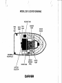
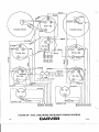
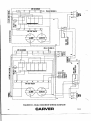
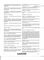
MODEL 2357 LOCATOR DRAWING
HOLDING TANK
FUEL
TANK
SHOWER
PUMP
DOCKSI
RECEPTACLE
CIRCUIT
BREAKER
PANEL
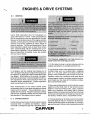
BATTERY SELECTOR CARVER ENGINES & DRIVE SYSTEMS B-1 GENERAL Carver Boat Corporation does not manufacture en
gines, stern drives or v-drives. These components are
built by manufacturers that are specialists in this field.
Because of the technica I nature of the engine and drive
systems, all manufacturers of these items require that
warranty and service problems be taken directly to
them for resolution. The Service Department of Carver
Boat Corporation stands ready to assist boat owners
when communicating with the manufacturers of en
gines and drive systems. Prior to contacting the Carver
Service Department, thoroughly review any problem
with your Carver dealer.
The following suggestions can help prevent ex
haust fumes from entering your boat:
1. Do Not allow the boat to remain stationary with the
engines operating for an extended period of time.
In compliance with the Federal Safe Boating Act of
1971, all engine manufacturers require their products to
be registered. A registration card is furnished with each
new engine. When selling a Carver boat, the dealer,
along with the purchaser, should complete the informa
tion requested on these cards and return them to the
respective engine manufacturer. (Engine registration
cards can be found in this manual).
Most manufacturers of the various marine power
components used in these boats provides an owners
manual with the product. These publications are in
cluded with this manual. Read the manual(s) carefully
and become completely familiar with the proper care
and operation of the engine and drive system.
B-2 ENGINE EXHAUST
Do Not inhale exhaust fumes! Exhaust contains carbon
monoxide which is colorless and odorless. Carbon
monoxi(:le is a dangerous gas that is potentially lethal.
OMSB
2. Use extreme caution while operating the engines in
confined areas such as enclosed slips, congested
piers, or in any area where the exhau!)t outlets are
facing or near a bulkhead or wall structure of any kind.
Operation under such conditions could easily lead to
exhaust gasses (carbon monoxide) entering the boat.
even though you may have all the hatches, windows,
doors and portholes closed.
3. Neveroperatethegeneratorwhiletheboat is moored
against any other boat, dock or wall structure that is
against or near,the exhaust outlet. Again, operation
under such conditions could easily lead to exhaust
gasses (carbon monoxide) entering the boat orthe boat
to which you are moored, even though you may have all
the hatches, windows, doors, and portholes closed,
4. Persons sleeping can be easily overcome by carbon
monoxide because they are unaware of its presence.
Sleeping while the engines or generator are running is
llQ1 recommended. If persons are sleeping aboard while
CARVER
81
underway, or while the generator is running, those
awake should be extremely watchful for carbon monox
ide accumulation in the cabin; especially the sleeping
areas. Open forward facing windows or deck hatches
to provide adequate fresh air ventilation. Keep hatches,
windows, and doorways that face aft or towards the
exhaust discharge closed.
5. Ventilate your cabin while underway. Open a forward
hatch, porthole, or window to allow airto travel through
the cabin. Be very careful of operating the boat with the
cabin door or other windows, hatches, or portholes that
face aft, open. The natural vaccuum created during
operation may allow exhaust gasses to be drawn into
the cabin.
6. Inspect the engines exhaust system frequently.
7. Have a competent marine engine service technician
inspect the exhaust system whenever the boat is in for
service, or if a change is noted in the sound of the
engines.
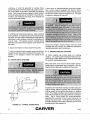
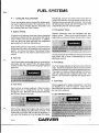
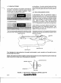
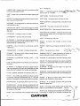
B-3 STERN DRIVE SYSTEMS
A stern drive or inboard/outboard propulsion system
has a piston engine equipped with special marine
components mounted near the transom and coupled to
an external outdrive type transmission unit. Thistype
of system is depicted in Figure B1.
Consult the Engine Owners Manual that has been
provided with this manual for additional information
regarding operation and maintenance.
B - 4 ENGINE COOLING SYSTEMS
All marine engines use surface water as a cooling
medium. The cooling water employed enters the sys
tem through a water intake and is relinquished through
the exhaust manifolding system.
Most stern drive units have the water intake and ex
haust system incorporated into the outdrive. See the
Engine Owners Manual for additional information.
Installation of "Fresh Water Cooling" provides adequate
engine cooling without exposing the internal engine
cooling system to the detrimental effects of surface
water. Fresh Water Cooling is recommended when the
boat will be operated in salt, highly polluted, or silt laden
water. Ask a Carver dealer for recommendations
regarding the necessity of fresh water cooling in the
boating area to be used. The Engine Owners Manual
provides additional information regarding service and
maintenance of this equipment.
FIGURE B1 • TYPICAL STERN DRIVE 82
CARVER OMS8
prop slip of 30%, would move the boat at a rate of 24
miles per hour.
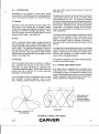
8 - 5 PROPELLERS
Knowledge of the propeller is most easily gained
through better understanding of the terminology used to
refer to the aspects of propeller size and performance.
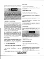
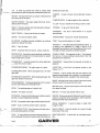
A. Diameter
Diameter is twice the distance from the center of the
prop shaft to the extreme tips of propeller blades.
Increasing or decreasing propelle r size will have a di rect
bearing on the RPM's an engine will develop. This is
due to the greater amount of propeller blade su rface in
contact with the water. See Figure 82.
8. Pitch
Pitch is a measure of helix angle (or angle of attack) of
the rotating blade. Pitch is easily understood by imag
ining the propeller rotating through a semi-solid such as
butter or jello. The distance the propeller will travel in
one revolution is called "Pitch." Increasing or decreas
ing pitch will have a direct bearing on engine RPM's
because of the greater bite taken by the blade with each
rotation. See Figure 82.
C. Prop Slip
Changing either diameter or pitch will have an effect on
engine speed and prop slip, and in turn, directly effect
the performance of a boat. The propeller(s) included
with each Carver boat provide the best general perform
ance based on data obtained from on-the-water testing
of that model. Variations in load, operating conditions,
environment, the individual engine and hull perfor
mance may necessitate the purchase and use of an
other propeller(s).
Under your normal load conditions the engine(s) should
turn within the maximum RPM range when at full
throttle. If the engine(s) exceeds the recommended
RPM an increase in pitch or diameter is required. A
decrease in pitch or diameter required if engine RPM is
too low.
An engine that is not developing full power, and the load
carried in a boat, will directly effect performance of the
engine. Always be sure the engine is properly tuned,
and that load conditions are those normally experi
enced, before changing propellers.
For a further explanation of conditions effecting propel
ler RPM, see a Carver dealer.
When traveling through water a propeller is unable to
get a complete bite because of the fluidity of water.
"Prop Slip" is usually expressed as a percent of the
computed theoretical speed. Twenty-five to thirty-five
percent prop slip is common for a cruiser type boat
operating at cruising speed.
From the definition given, the deduction can be made
that a propeller, of a given diameter, with a 10 inch
pitch, rotating at 3600 revolutions per minute, with a
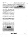
8 - 6 ENGINE INSTRUMENTATION
Each pilot station is equipped with a complete set of
engine instruments. These instruments allow the pilot
to constantly monitor the operational condition of the
engine. Diesel engine boats may use visual indicators
instead of gauges. Close observation of these instru
ments could save the engine from damage.
Prop makes one
revolution thru
viscous medium
zero slip condition
..~
Prop Pitch
R=Radius • Diameter=2 x R Prop Diameter FIGURE 82 • PROPELLER THEORY OMSB
CARVER
B3
E. Fuel Gauge
The Fuel Gauge displays the level of fuel that is present
in the fuel tank(s). See section E for more detailed
information on fuel gauge operation.
F. Power Trim Gauge
A. Tachometer
The Tachometer indicates the speed of the engine in
revolutions per minute. This speed is not the boat
speed nor necessarily the speed of the propeller. The
Tachometer may not register zero with the Ignition Key
in the OFF position.
Boats equipped with MerCruiser Stern Drives also have
a "Power Trim Gauge." This gauge provides a visual
indication of the inward-outward position of the
outdrive. If the boat is equipped with a second control
station, an optional Power Trim Gauge can be added to
that station.
G. Engine Alarm Systems
Engine alarm systems are installed on some models
with specific types of engines. The alarm is an audible
alarm that is mounted in the helm area; it is actuated by
engine water temperature and engine oil pressure
senders. The alarm will sound in the event of low engine
oil pressure or high engine water temperature.
B. Temperature Gauge
The temperature gauge monitors the cooling system of
the engine. A sudden increase in the temperature cou Id
be a signal of a blocked cooling passage or a water
pump malfunction.
. The engine alarm will sound during engine startup, or
whenever the Ignition Switch is positioned to ON and
the engine is not operating. The alarm sounds under
these conditions because engine oil pressure is low; the
alarm will cease to sound as soon as engine oil pressure
rises to the proper level.
IMPORTANT: The engine alarm systems installed in
these boats monitors only engine water temperature
and engine oil pressure. Always maintain a close visual
watch on the drive(s), transmission(s), engine fluid
levels, bilge water level, etc.
C. Oil Pressure Gauge
H. Engine Synchronizer
The Oil Pressure Gauge provides an indication of the
pressure in the engine lubrication system. A drop in oil
pressure is a possible indication of oil pump or leakage
problems.
Most dual engine Carver models can be equipped with
an optional engine synchronizer. This instrument com
pares the electrical signals generated by the. engines
and converts those signals to a visual meter indication
of engine speed difference. The meter movement
responds to changes in throttfe position. When the
needle is centered, the engines are in proper synchron
ization.
'
I. Instrument Maintenance
D. Voltmeter
Electrical protection for instruments and ignition cir
cuitry is provided by a fuse or cirucit breaker on the
instrument panel.
The voltmeter monitors the battery condition. See Sec
tion E for additional information on voltmeter operation.
Periodically, spray the Ignition Switch(s) with a contact
cleaner/lubricant such as LPS, CRCor WD40. The
B4
CARVER OMSB
Ignition Switch(s) and aI/ instruments, controls, etc.
should be protected from the weather when not in use.
Carver offers appropriate weather covers for each
model. Excessive exposure can lead to gauge and
Ignition Switch difficulties.
Electronic gauges are affected by static electricity that
builds-up on the glass face. Periodic washing of the
gauge face with warm water and mild liquid detergent
will help eliminate the static electricity problem and
improve gauge accuracy.
OMSB
CARVE'R
85
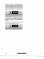
PROPULSION EQUIPMENT MODEL
ENGINES
REDUCTION
PROP
2157
3.7L MERe
4.3L MERe
5.7L MERe
171 VOLVO
205 VOL va DUO PROP
1.84:1
1.84:1
1.50:1
2.15:1
2.3:1
16 X 14
16 X 16
16 X 16
16 X 13
8-6
2357
4.3L MERe
5.7L MERe
205 VOL va DUO PROP
~ 271 VOLva DUO PROP
1.84:1
1.50:1 .
2.3:1
1.95:1
14-1/2 X 17
14-1/2 X 17 8-5
8-5
1.50:1
1.5:1
1.95;1
16 X 16
15-1/2 X 17 RH SS
8-5
.
2557
Single
5.7L MERe
7.4L 8RAVO MERe
271 VOLVO DUQPROP
Twin
3.7L MERe
171 VOLVO
2587
Single
5.7L MERe
7.4L 8RAVO MERe
271 VOLVO DUO PROP
TWIN
5.0L MERe
231 VOLVO DUO PROP
2757
---..
1.50:1
1.5:1
1.95:1
Single-Gas
271 VOLVO DUO
. . . . . .PROP
.
Twin-Gas
3.7L MERe
4.3L MERe
171 VOLVO
205 VOL
va DUO PROP
...- - - - -...
Twin-Diesel
AQAD 31 VOLVO DUO PROP
r-'~~-
2767
1.84:1
2.15:1
---~.---
~
~-
.~-~.
--.~~-~~---~--~.
Single-Gas
271 VOLVO DUO PROP
--- Twin-Gas---"--'--' 3.7L MERe 4.3L MERe
171 VOLVO
_~05 V_QLVODUP PROE_.__ .
Twin-Diesel
AQAD 31 VOLVO DUO PROP
B6
.~-""~-------'-'~---'~--'---.
13-3/4 X 21
16 X 17
.16X16
15-1/2 X 17 RH SS
8-5
1.5:1
1.95:1
14 X 19
8-6
1:95:1
8-4
,
1.84:1
1.84:1
2.15:1
2.3:1
2:3:1
1:95:1
14 X 19
13-3/4 X 219
16 X 15
8-7
"--'~-----~---~~---'-
8-5
8-3
.------.-------~-
...------.--.-.
1.84:1
1.84:1
2.15:1
2.3:1
14 X 17
13-3/4 X 21
16 X 15
8-6
2:3:1
8-5
CARVER OMSB
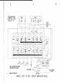
Tachometer
1--~--4-~Pi nk
purple
blue
bla k
c:
...III
purple
ellow/red
$
-..
red
V-drive light
$
:t
-..
.0
I f . 0 e qui p p e d ..............I..-L-"'-""--I..-L..... Engine Harnel • V-drive 011 lender
FIGURE 83 • SINGLE GAS ENGINE INSTRUMENT WIRING DIAGRAM
OMS8
CARVER
87
black
black
Tachometer
Tachometer
fIJ
...
Q.
-..
:)
Q.
•
Jtt.
fIJ
U
Q.
.Q
:::II
...
:J
Q.
Q
if so equipped
FIGURE 84 • DUAL GAS ENGINE INSTRUMENT WIRING DIAGRAM 88
.CARVER OMSB
\
)
)
)
o
:!:
(f)
OJ :!!
c:
Single Engine
G)
Dual Engine
1
JJ
m
[D 01 •
en
z
r
G)
m
Ro
I
o
c:
l>
r
~
~m
Single ;statron
<
o
r
0< __ m
z
lJ
Abbt"~v.ated Wirs CQ(ot"s
G)
b'lack-k
z
bhHJI-b
z
en
-I
g.f.on-n
m
JJ
c:
bl
yeHo'fr-Y
whlhl-W
~fay-o
ortkng4t""O
brown-bn .
'" -I
§ N"l~: To ola.I,
JJ
t~ .&con~ 'ON'
Z
I
turn kay 1eo degrEt198
o
:.;:
G)
JJ
l>
s:
~
~I",'1
I
z
tlon
po.i.
I
li--1.
=:f!0.:t! II
o
s:
m
G)
~
rcd-r
I
\-
I
~
____
---
_4_
0i"
'.
.-J
n
I
~5
.
R'
I --.---:~ ~-~
~
~
Key
~~~
r1\
kl-
I
I:L~
@
~;:~"
fn- . 15
'@Ke
k
Stop
I
kl . Ji.
~f
~ Alo".
DUII11Stalion
I
Stop (I
II
"
Y
CONTROL SYSTEMS C-1
GENERAL
The remote control systems which permit operation of
the engine's throttle and shift mechanisms consist of
three major components, the control, the throttle and
the shift cables. The various types of controls and their
operation are discussed in section C-2.
The cables are all push-pull type. Two cables are
required. One connects the remote throttle control to
the carburetor and the other connects the remote shift
control to the outdrive or transmission shift linkage.
C - 2 CONTROL OPERATION
./'--.
The various mounting locations, number of control
stations with which the boat is equipped and the type of
engine installed are all important in determining the type
of control to be used. Each control is equipped with a
means of permitting the engine to be operated at high
speed while in neutral for cold starting and warm-up
purposes .
During the general operation of a dual engine boat, it is
adventageous both engines should be operated at the
same rpm. This reduces noise, and vibration and can
increase engine efficiency. Setting the throttles so the
engines are running the same rpm (synchronized) can
be done by the engine sounds or you can purchase an
instrument (Engine Synchronizer) as described in
Section B. Attempting to synchronize the engines
solely by using tachometer readings or control lever
plac~ment generally will not work. When the engines
are In proper synchronization, the throttle levers may
not necessarily be even.
See the information provided by the control manufac
turer. Details on co ntrol operation and maintenance are
provided therein. Also see the Engine Owners Manual.
than the neutral position. If the engine will not start
slight movement of the shift lever may be necessary t~
locate the neutral position and disengage the safety cut
out switch. Control or cable adjustments are required
to correct this condition should it persist. .See your
Carver dealer for necessary control and cable adjust
ments.
C - 4 DUAL STATION CONTROLS
Boats equipped with a dual station control system utilize
"station-to-station" cables to interconnect the upper
and the lower stations. Due to the added machinery, a
dual station control system is inherently stiffer operating
than a single station. This is usually more noticeable at
the upper station.
C - 5 CONTROL SYSTEM MAINTENANCE
Periodic inspections of the control(s), cables, and all
connections should be made. Signs of rust, corrosion,
wear, cable jacket cracks or other deterioration requ ire
immediate system servicing. If your unit is equipped
with electric shift, inspect the shift wire for fraying,
embrittlement and insulation cracks. Repair all noted
deficiencies.
>
Generally, periodic lubrication of all moving parts and
connections with a light, waterproof grease is in order.
Cables can be lubricated by positioning them to their
fullest extension and applying light grease to the inner
cable near the jacket. Working the cables back and
forth will distribute the grease in the inner cable. Re
apply the grease if necessary.
Lubrication should be performed as often as necessary
to keep the system operating smoothly. Cable manu
facturers such as Teleflex and Morse often offer special
tools to make cable lubrication easier.
C - 3 NEUTRAL SAFETY SWITCH
Cable and control adjustments may become neces
sary. Adjustment screws in the control, on the cables
Every control system has a neutral safety switch incor
porated into it. This device prohibits the engine from
being started while the shift lever is in position other
and in the linkage are provided.
OMSB
CARVER
r-------------------~---
C1
. . . - -.. . - -.. Other lubrication, adjustment and maintenance instruc
tions are included in the information provided by the
control manufacturers.
C2
CARVER OMSB
STEERING SYSTEMS 0-1 GENERAL
0-2 'OUTDRIVE POSITION INDICATOR
A. Mechanical Steering
Some Morse helm assemblies are equipped with a
rudder position indicator. This device indicates the
location of the stern drive relative to the straight ahead
position. The position indicator operates mechanically.
Proper adjustment and free operation are essential if
proper rudder position indications are to be provided.
Periodic lubrication of all moving parts within the rudder
position indicator is necessary to maintain smooth
operation.
Most single station Carver boats use a rack and pinion
type mechanical steering system. In this system, a
pinion gear in the steering helm drives a gear rack
attached to the helm end of the steering cable. A rotary
rack is sometimes used. Though the appearance is
different, the concept is the same. The steering cable
is of the push-pull type. As the wheel turns, the pinion
drives the rack which pushes or pulls the steering cable.
The steering cable on a stern drive model connects to
the outdrive steering linkage, orthe power steering unit
if so equipped.
B. Hydraulic Steering
o -3
PROPELLER TORQUE
Propeller rotation by a single engine installation will
exert a directional force on the steering system. This
action can cause steering to be harder in one direction
than the other; this is referred to as propeller torque.
Most dual station Carver models use hydraulic steering.
The Hydrau lic Steering System consists of three major Stern drive units are equipped with an adjustable tab on the drive unit to compensate for porpeller torque. This components: the helm assembly, a pressurized reser
.
voir, and the hydraulic cylinder. The helm assembly tab is used to attain a neutral steering condition at acts as a pump to move the oil through the system. In normal operating speed. When this condition is at
many aspects this type of steering is similar to the tained, equal force will be required to turn the steering mechanical system. Instead of activating a cable, wheel to both port and starboard. See the Engine turning of the helm causes fluid in the hydraulic hoses Owners Manual for more data.
toflow and activate the hydraulic cylinder causing the
rudders or outdrive to turn.
Propeller torqu e can also prevent the boat from follow
ing a straight line, or to wander when operated at very
As the wheel is rotated, a slight clicking sound may be low speed. This condition is normal and can be cor
noted. This clicking sou nd is the opening and closing of rected by increasing engine rpm. Wind, water currents
the valves in the helm unit and is normal.
and play at steering conditions can cause equivalent
effects.
As the steering wheel is turned, the water flow past the
rudders, or outdrive, places a load on the steering 0-4 POWER STEERING
system. The effort required to turn the steering wheel
Boats equipped with MerCruiserstern drives are, orcan
remains constant regardless of speed or outdrive posi
tion. This is an advantage when the boat is "on plane". be, equipped with MerCruiser power steering. This is a
The lack of steering effort can be a disadvantage at "power assist" system and can greatly reduce steering
lower speeds because the effort is not reduced to where efforts. However, this system is not a full power
steering system as used in automobiles, some steering
it can turn lock-to-Iock easily.
tension remains in the system.
The torque tab, on stern drive models with hydraulic
steering, must be properly adjusted; see section D-3.
Though the helmsman may not feel propeller torque on
the wheel, an improperly adjusted torque tab can cause
steering difficulties.
For additional information, see the Steering System
Manufacturer's literature that is included with this
manual.
OMSB
Upon commissioning the boat, the system must be
purged of air. Should steering difficulty increase with
CARVER
D1
- - - - - -.. - -
time, additional bleeding ofthe system may be required.
See a dealer; adjustments on a power steering unit
must be performed by a qualified service technician.
Proper power steering fluid level must be maintained.
See the information provided by the power steering
manufacturer for additional information.
D - 5 POWER STEERING MAINTENANCE
Make a periodic inspection of all steering cables, link
age and helm assemblies. Immediately correct signs of
corrosion, cracking, loosening of fastenings, excessive
wear, or deterioration. Failure to do so could lead to
steering system failure and loss of control.
Adjust the helm and cable assembly so that the system
is centered with the rudders or outdrive in the straight
ahead position. The steering wheel should be able to be
rotated an equal number of turns to port and starboard
from the straight ahead position. If adjustment be
comes necessary, see your Carver dealer.
All cables, helm assemblies, and steering connections
should be periodically lubricated with a light, waterproof
grease. See the manufacturers information provided
with this manual.
Hydraulic steering systems must have all air purged
from system periodically. Some hydraulic steering
systems must be pressurized to achieve optimum
operation. These systems usually require 20-30 psi
pressure. Review the information provide(j by the
hydraulic steering manufacturer for proper system
specifications and details regarding system service and
maintenance.
D2
CARVER OMSB
ELECTRICAL SYSTEMS E-1
or the main circuit protection device (either fuse or
circuit breaker).
GENERAL
All electrical equipment on Carver boats operates on
either 12 volt DC or 120 volt (220 volts on 50 Hertz
models) AC electrical power. An understanding of the
systems and their operation can be easily gained
through a study of the major components which com
prise the electrical circuitry. Section E describes the 12
volt system and the related operation. Also in Section E
is a description of the 120 (220) volt system.
E - 2 BATTERY SYSTEMS
The OFF position of the Battery Selector Switch will
completely shut off 12 volt electrical power. The only
exceptions are the voltmeter (described in Section E)
and automatic bilge pump (described in Section E).
Always turn the Battery Selector Switch to the OFF
position or place the main circuit breaker in the OFF
position when the boat is left unattended for an ex
tended period.
Positioning the Battery Selector Switch to the #1 posi
tion will provide power to the 12 volt electrical system.
In single battery installations, the #2 position of the
Battery Selector Switch is not functional.
A Single Battery Systems
A 1 Installation
A single 12 volt DC battery is standard equipment on
certain models. A Battery Selector Switch (see the
Locator Drawing in Section 0 for the exact location of
the Battery Selector Switch) is provided on models with
2 batteries.
INPORTA NT: Extended use of 12 volt equ ipment with
out operating the engine or charging the battery cou Id
seriously damage the battery.
B Dual Battery Systems
B1 Installation
Connect the battery in the following manner:
1. Connect the red battery cable from the Battery
Selector Switch to the positive (+) terminal of the
battery.
The Battery Selector Switch (see the Locator Drawing
in Section 0 for the exact location o.f the Battery
Selector Switch) that is provided on models with two
batteries enables DC power to be used from either or
both batteries.
2. Connect the black cable from the engine to the
negative (-) battery terminal.
When installing the batteries, proceed as follows:
3. Also connect the black lead from the power trim
pump, if so equipped, to the negative (-) battery termi
nal.
1. Connect each of the two red cables leading from the
Battery Selector Switch to the positive (+) terminal on
each of the two batteries.
4. Other black leads for 12 voltequipment, such as
those labelled A, A 1, and AD, must also be connected
to the negative (-) battery terminal.
2. Connect each of the black cables from the engine to
each of the negative (-) battery terminals. On dual
engine boats there will be one black cable coming from
each engine. Single engine boats will have two black
cables coming from one engine. Any black leads for the
power trim pump, etc. must also be connected to the
negative (-) battery terminal.
A2 Operation
All factory installed 12 volt equipment, except for the
automatic bilge pumps and the voltmeter, are con
nected to and controlled by the Battery Selector Switch
OMSB
CARVER
E1
3. The black leads from the 12 volt distribution panel
labelled A must be connected to the negative (-) battery
terminal.
4. If the boat is equipped with a battery charger,
connect the red leads labelled C1, C2, and C3 to the
positive (+) terminals of batteries 1 & 2 (and the
generator battery if so equipped). Also, connect the
black ground wire C 1 to the negative (-) terminal of any
battery.
B2. Operation
Power to the engines and all 12 volt electrical equip
ment, except the automatic bilge pump and voltmeter,
is controlled by the Battery Selector Switch.
Battery Selector Switch Positions:
"OFF" - With the Battery Selector Switch in the OFF
position, all 12 volt power to the boat is shut off except
for the bilge pumps and voltmeter. Always turn the
Battery Selector Switch to the OFF position when the
boat is unattended for an extended period.
"1" - Position 1 will use battery #1 to power both
engines and all 12 volt equipment. Battery #2 will be
isolated and remain in reserve. Battery #1 will be
charged by the alternator(s).
"2" - Position 2 will use battery #2. Except for automatic
bilge pumps and voltmeter, battery #1 is isolated and
remains in reserve. Battery #2 will be charged by the
alternator(s) .
"ALL" - With the Battery Selector Switch in the ALL
position, the batteries are connected in parallel. Both
batteries will be used by the engines and all 12 volt
equipment.
The use of one battery at a time is recommended. Use
one battery at a time by positioning the Battery Selector
Switch to either the #1 or #2 position. Avoid using the
ALL position. Use the ALL position only when a single
battery is not capable of starting the engine(s).
Alternate battery usage increases battery longevity.
Use battery #1 for the first day of a cruise and switch
to battery #2 on the second day.
alternators to charge the low battery. Utilizing the
Battery Selector Switch in this manner (instead of using
the ALL position) will supply a greater charge to the
battery.
FOR EXAMPLE: If battery #1 is fully charged and
battery #2 is in need of a charge, use battery #1 to start
the engine(s). After the engine(s} are operating and
warmed-up, turn the Battery Selector Switch to the #2
position. This will permit the alternators to charge the
low, #2 battery.
E-3
BATTERY CARE & MAINTENANCE
Keep the batteries charged and filled to the proper level
with distilled water Keep the batteries clean, especially
the terminals and connection lugs. Be sure the batter
ies are fastened securely while in use.
IMPORTANT: If a 120voltbatterycharger is used, be
sure the 120 volt neutral lead of lhe charger is isolated
from the ground or bonding circuit. Be sure the battery
charger is of the type which properly senses battery
requirements and does not overcharge or cause the
electrolyte to boil.
Periodically inspect all electrical wiring to ensure clean
secure connections. Also, inspect for nicks, chaffing,
embrittlement, improper support, etc. Have any de
fects corrected immediately by an experienced marine
.
electrician.
E - 4 VOLTMETER USE & OPE RATION
Voltmeters are provided to monitor the condition of the
batteries. Replenish a battery indicating a low charge.
Determinethe reason forthe discharge. Lack of battery
usage is as detrimental to battery longevity as is over
use. Alternate batt~ry usage is important.
When two batteries and a single Voltmeter are pro
vided, a Voltmeter Switch is supplied on the helm
control panel. When the engine(s) is not running and
the battery charger is off, depressing the Voltmeter
Switch towards position #1 will indicate the voltage of
battery #1. Similarly, the voltage of battery #2 will be
indicated with the switch depressed towards #2. The
center position is off. When the Voltmeter Switch is
employed during engine operation, the voltage of the
CARVER E2
r----~----
Monitor the voltmeter. Position the Battery Selector
Switch to the battery that has sufficient power to start
the engine(s). Start each engine independently; never
try to start both engines simultaneously. After the
engine(s) is operating, position the Battery Selector
Switch to the battery that has the lowest charge. This
will allow the
. - - - - - -......
--~---
...
-----~
.-.. - - - -.. . . - - - - -
OMSB
respective battery. plus any electrical charges supplied
to it, will be indicated on the Voltmeter.
IMPORTANT: Be sure the Voltmeter Switch is in the
OFF position when not in use, especially while the boat
is unattended. The voltmeter is independent of the
Battery Selector Switch and if left on, it will drain the
charge from the batteries.
Voltmeter - The Voltmeter will register the amount of
charge available at the battery or batteries. If a boat is
equipped with two batteries and one voltmeter, a Volt
meter Switch will be provided to permit selection of the
desired battery.
Bilge Blower- The BLOWER Switch is used to activate
the bilge blower. The bilge blower is used to remove any
gas vapors that may have accumulated in the bilge or
engine areas. On dual station boats. the blower can
only be turned off althe station from which it was activa
ted.
E - 5 12 VOLT ELECTRICAL EQUIPMENT
A. Helm Equipment
Panel Lights - The Panel Lights Switch is used to
activate the helm console panel lights.
Horn - The HORN Switch sounds the horn for as long
as switch is manually held depressed.
Wipers - The WIPER SWitch activates the windshield
wipers. On dual station boats, a WIPER Switch is not
provided at the upper station.
Spotlig ht - The Spotlight controls are in the dash panel.
For further information regarding spotlight use and
operation. refer to the manufacturers literature.
Nav. & Anchor Lights - Moving the NAV/ANCHOR
Switch towards the NAV position activates the side.
stern. and20 pt.light. MovetheSwitchtotheANCHOR
position to activate the anchor light. The center position
of the switch is OFF.
NOTE: Some models have independent switches for
the Nav and Anchor lights.
Fuel Gauge - Boats equipped with a single tank have
a fuel gauge that will register the fuel level when the
Ignition Switch is in the ON position. Models equipped
with two tanks either have two Fuel Gauges or a dual
position FUEL Switch. If a FUEL Switch is provided,
fuel level is determined by placing the Ignition Switch in
the ON position and moving the FUEL Switch towards
the position that indicates the desired tank. The FUEL
Switch is spring-loaded to return to the center-OFF
position upon release.
OMSB
Bilge Pump - Bilge Pumps are used to remove water
from the bilge (bottom of the hull) area of the boat by
pumping that water overboard. The Bilge Pump Switch
is used to either cause continuous operation ofthe Bilge
Pump(s) or, operation when a predetermined level of
water accumulates in the bilge. Continuous Bilge Pump
operation is caused by placing the Bilge Pump Switch
in the CONTINUOUS positon. When in the AUTO
MATIC position, the bilge pump will be activated auto
matically. Automatic operation will commence when
ever bilge water rises to a level that will cause the bilge
float switch to move upward.
The Bilge Pump will remain active if placed in the
AUTOMATIC position even if the Battery Selector
Switch is the OFF position. The Bilge Pump Circuitry is
connected directly to the batteries and is protected by
inline fuses or circuit breakers that are located nearthe
Battery Selector Switch.
IMPORTANT: Before leaving your boat unattended for
an extended period; ensure that the Bilge Pump Switch
is in the AUTOMATIC position. This will provide auto
matic draining of the bilge should a leak develop while
the boat is unattended. Check the water level in the
bilge often.
'
Trim Tabs - The Trim Tabs are used to cause the bow
of the boat to move up or down while underway. This
action in turn can cause more efficient operation of the
boat. Ifthe boatis equipped with Electric-Hydraulictrim
tabs, the trim tabs are controlled by the Trim Tab Up or
Trim Tab Down Buttons. Section J contains additional
information regarding usage of the Trirn Tabs.
CARVER
E3
the related floor panel. See the locator drawing in
Section 0 for exact location of the water tank(s).
B. Interior Equipment
The MAIN circuit breaker protects all12 volt distribution
circuitry. There are also individual circuit breakers for
items such as the refrigerator, stereo, inte rior lights, etc.
A separate fuse may be mounted in the cockpit when
the optional cockpit washdown system is installed.
Section G has additional information regarding the
cockpit washdown system.
D. Installation of Additional 12 Volt Equipment
Negative and positive terminal blocks are installed near
the helm switch panel. Leads for non-factory installed
12 volt accessories can be connected to these terminal
blocks.
C. Head Electrical Equipment .
Shower Pump - Shower pumps are used to discharge
shower water overboard. The shower pump is acti
vated either by a manually-operated switch that is
located near the shower or by an automatic sump
system.
f the boat is equipped with a Switch labeled SHOWER,
place this Switch in the ON position to activate the
shower pump and thereby discharge shower drain·
water overboard; place this Switch in the OFF position
when done.
If the boat is equipped with a shower sump system,
shower water will automatically be discharged over
board as soon as the water level in the shower water
sump reaches a level that will cause the float switch in
thesumpto riseto a predeternined level. Thepumpwill
automatically shutdown when shower water ceases to
flow.
NOTE: Regardless of the type of shower pump activa
tion with which the boat is equipped, the Shower Circuit
Breaker must be in the on position for either system to
function.
Pressure Water - Water is delivered to all output
devices, e.g., faucets. by meansof pressure. Pressure
to deliver the water is created by the Pressure Water
Pump. The pressure water pump will operate automati
cally on-demand as long as the Pressure Pump circuit
breaker is in the ON position. When the water tanks
aboard the boat are empty, place the pressure pump
circuit breaker in the OFF position.
NOTE: If the boat is not equipped with a Water Level
Gauge, water level can be determined by viewing the
water tank. Watertanks are normally located below the
floor in the bilge area and can be accessed by removing
E4
All of the items listed in section E-5A, B & Care
protected at the main circuit breaker or fuse panel.
Fuses or circuit breakers for the voltmeter and auto
matic bilge pump are located near the Battery Selector
Switch. The instrument and ignition fuses or circuit
breakers are located on the helm control panel.
E-6 120 (220) VOLT ELECTRICAL SYSTEM
The boat may be equipped with 30 amp, 120 volt, 60
Hertz (or 15 amp, 220 volt, 50 Hertz) AC electrical
wiring. When the boat is connected to a shore power
outlet, the AC system supplies electrical ower to items
such as dual voltage refrigerators. stoves, battery
chargers, and receptacles. See the Locator Drawing in
Section 0 for exact location of the Dockside recep
tacles.
E-7 AC SYSTEM GENERAL INFORMATION
The dockside system uses three-wire, color-coded
circuitry. The black or hot wire is the ungrounded
current carrying conductor. The white or neutral wire is
the grounded current carrying conductor. The bare
copper or green wire, referred to as the "equipment
ground," is a grounded conductor, and under normal
conditions is not a current carrying wire. The neutral
wires are connected together at a buss bar. The
equipment grounds are similarly connected together at
another buss bar. Each hot wire is connected to, and
protected by, a circuit breaker in the distribution box.
The distribution box houses the system circuit break
ers. The standard dockside system has a MAIN circuit
breaker which protects the overall distribution network.
The main breaker protects both the hot and neutral
input leads. The MAIN breaker will also trip if reverse
polarity should occur. . This breaker is very sensitive.
The resulting power surge which occu rs when connect
CARVER OMSB
-
ing in the shore power cord may cause the MAIN
breaker to trip. To avoid this power spike, turn off all
MAIN breakers before plugging in the shore power
cord(s). Securely connect the power inlet of the boat
and the shore power receptacle. If the connection is
broken and later re-secured, the circuit breaker will trip.
Connections must be secureforuninterrupted dockside
service.
If the boat is equipped with dual dockside, a second
distribution system, that is similar to the one previously
described, is provided. This is a completely separate
system which includes another main breaker, power
inlet, dockside cord, etc. The second AC system is
normally provided whenever equipment that requires
large amounts of current (e.g., air conditioning) is
provided.
E - 8 DOCKSIDE OPERATION
AC EQUIPMENT ELECTRICAL LOADS
Air Conditioners
Battery Chargers
Blankets (Electric)
Coffee Makers
Electric Drill
Fans
Fry Pan
Heater
Lights
Television
Toaster
Vacuum Cleaner
See motor load plate
Up to 800 watts (7.3 amps)
50 to 200 watts (2 amps)
550 to 700 watts (6.3 amps)
See motor load plate
25 to 75 watts (0.7 amps)
1350 watts (12.3 amps)
1500 watts (13.7 amps)
wattage as marked
200 to 300 watts (2.7 amps)
800 to 1500watts (1 0.5 amps)
See motor load plate
Usually, the power requirement is specified on the
electrical item. The table previously listed is only an
approximation of the electric current usage normally
experienced.
Some boats are equipped with optional volt and amp
meters. If so equipped, monitor these meters; amper
age draw must not exceed 30 amps (15 amps on 50
Hertz systems).
B. Shore Power Connections
/-
A. General
Appropriately labeled breakers control actuation of the
electric stove and electric hot water heater. The electric
stove also has heat controls governing the burner
elements.
Fifty foot, ten gauge, three wire, shore power cords are
provided with dockside wiring. The shore power cords
on 60 Hertz systems have 30 amp twistlock'type
connectors. This connector is approved by Boating
Industry Association, and the American Boat and Yacht
Council. Always connect the cord to the power inlet
receptacle of the boat before making connections to the
shore power source.
The AC receptacles can be used for 120 volt (220 volts
on 50 Hertz models) household appliances.
Some marinas are not equipped with approved twis
tlock type receptacles. An adaptor is available from
Carver which converts the twistlock shore plug to a
three wire grounded household type plug. Use only an
approved adaptor when an adaptor is necessary.
OMSB
CARVER
E5
E· 10 ELECTROLYSIS & CORROSION
Two types of electrically induced underwater corro
sion occasionally affect boats and the related compo
nents. This corrosion appears as surface pitting or de
terioration. These two types are as follows:
A. Electrolysis
C. Polarity indicator
If the dockside power source is incorrectly wired and
has the polarity reversed, the MAIN circuit breaker will
sense the voltage difference between the neutral and
ground terminal blocks, this will trip the MAIN breaker.
The reversed polarity indicator will remain illuminated
even though the breaker has tripped.
E - 9 ELECTRICAL SYSTEM MAINTENANCE
Periodically, inspect all wiring for nicks, chaffing, em
brittlement,
improper support, etc. Examine the
shore power cord closely for insulation cracks and
corrosion in the electrical devices. Spraying the recep
tacles and electrical connections with an electrical
connection cleaner, such as "LPS"or"CRC,"will reduce
corrosion and improve electrical continuity.
The entire 120 (220) volt circuitry, especially the shore
power cord, should be seasonally tested for proper
continuity by an experienced marine electrician. This
will help detect any short, open wire, or ground fault.
Also, check the polarity indicator system for proper
operation.
The use of some shore power battery chargers, while
the boat is in the water and the battery is connected to
the system, can cause electrolysis. Have an ex
perienced marine electrician ·review any battery
charger installation to ensure an electrolysis problem
will not develop. Be sure the battery connections are
properly made. Improper battery connection, espe
cially the lack of a negative battery bonding cable on
dual engine boats, is a common cause of electrolysis.
B. Galvanic Corrosion
Electrical currents produced by two dissimilar metalsin
an electrolytiC solution is galvanic corrosion: Polluted
and salt water are much better electrolytic solutions
than clean, fresh water. Stern drive manufacturers
provide a sacrificial anode, either as a metal trim tab or
metal plate affixed to the boat transom. Periodic
inspection of this anode for decomposition, and its
replacement when it becomes worn, will increase the
longevity of stern drive units. Inboard boats, because
of the metal used for the underwater gear, are not as
affected by galvanic corrosion. However, if dockage is
in salt water, at a steel pier, near large metal boats, or
anywhere else where substantial metal is in contact
with the water, some form of corrosion protection
should be provided.
CARVER E6
r------------
Electrolysis is the decomposition of chemical com
pounds by electric current. Electrolysis can be caused
by the polarity of the dockside wiring system of the boat
being reversed from the power source or surrounding
boats, an improperly wired battery installation, other
boats that are in close proximity that have electrical
power leakages, or any other source close to the boat
that has electrical power leakage into the water. Stern
drive units are especially vulnerable to electrolysis.
However, it can attack a fiberglass hull and inboard
underwater gear. Make periodic inspections to deter
mine if electrolysis damage exists. Then determine the
source of the problem. If the source cannot be found,
it may be necessary to change the place of mooring.
..
.~--- ---~-
..
OMSB
~
:I
: I
Q
SIll 0f'I(»f)
0
I
q
Q
1
I
~
o
I
I
I
eo
t
I
I
I
I
I
!.--__
-lr~~
,
I
,
I
I
I
I
-.L.. - f -
I
i _'-
-L-
I
I
I
- - ! __
-
!:::
I
I
§. §
I
I
:r'\
I
I
I
I
,
,,
I
I
11
I
I
,
t
I
t
t-----i-+-T-'
I
I
l <. 5'" .
I
I
!
! I ().
r
0
:I
,
6
0
HV8 SOO ""Ml.I.fm
0
(
Q
Cb
'
reo j
F\
Kll1I\V
~
I
~
I
1
(~~"
1
I
~ ~
:
'
I
I
1
:!
(..)
I
1
,
I
~
1
ffi.Ll\llJA
\;;-~J ~/
J
1
I
:
Cb
CDt...-_.:--!l--+
~-:L _________________________________________________________
~
!
I
I
' ...
FIGURE E1 • DOCKSIDE WIRING DIAGRAM
OMSB
CARVER
E7
i--------------------------HVe-~~-------------l
~
I
c:.!)
I
~:
Q
0
,......---+'-0-.
I
Q-t- fGlSJS.· ~ICNOO 01
0
~_+---------~I--------~~'
c:.!)
:
......
~1~1~------4-------~
!:::
~
I
r-
l t""'\
....::
I
-L.
'-I-....-lf...-l-----J.......J
'I
f2:\'v
-
:~
! ~~
-~-~
I
~!
C"-I
:
'
I
I
I
: :
----------'
I
r-=-J~--1()----O-----O-----ct~
:
..
==r:::':i
I
'--I----I---:r-:--+l-----,t----=ea:=-----r
- !r-I-____~----_+"7./ T
e:
~------~I~------------------~_~--
MVB SOO ~
:
I
,
-
:
:I
I
is
a!
I
!
~!
I
r:o\ fc~
Hll1fW
"J~./
I
H311U.1JA
1
I !
'
!
\...33-77
..
I
-----------------------. -------------------------,
:----------"----------------------------------------------,
l
:I
;
I,
.1
IUJ.S).S~ cm:I 01 :
HVB SI1HNlOm
t Q
Q
I)
I
I
0(;)
Q
I
A
:I
.-+--=
..0-1"":.-p:;'
1
r---c;
~----------------~,~
p:; r=;
~~
_~
,
,
..
lea
I
I
•
I
I
I
:I .------+---.....
I
I
I
I
I
,
I
I
I
I
I
I
I
:~
I
I
I
I
I
r----~_l
:
~
! ~~$1~
=U~~I:3~- 1m ~
t
-
H..:::.4-Jt=t:=:
I )
I
I
I
I
I
()
o
0
HVBSlll ~
0
(/-; ' \
i--;'\
j
I
il!!
c:.!)
:
I
H1I.JItv
(~I
()
I
I
I
!
I
I
I
I
I
I
I
H3.l1U1)/\
"'4-/ '" ~j
1
1
I
:
",4-:i----+-+------+-~:=-+-
L _________________________________________________________ I
I
' ..
..
FIGURE E2 • DUAL DOCKSIDE WIRING DIAGRAM E8
CARVER OMSB
CODE COLOR
~
GA
USAGE
ROUTING SWITCH
FUSE
REMARK
4
10
10
10
Primary Input ..........
Ground lead ............
Access. gnd-bridge ..
Access. gnd-console
Batt. main to fuse ....................... . ---- .............. 30/60..
Upper to lower terminal block ..... .
..............
Bridge to elec. center ground ......
..............
Console to elec. center ground .. ..
..............
................ 14
................ 14
................ 14
................ 14
................ 14
................ 14
................ 14
................ 14
................ 14
................ 14
................ 14
................ 14
................ 14
Aft bilge pump ..........
Fwd bilge pump ......
Fwd bilge pump ......
Shower pump ..........
Aft bilge pump ..........
Aft bilge pump ..........
Fwd bilge pump ......
Fwd bilge pump ......
Washdown pump ....
Aft shower pump ......
Bilge pump light ......
Bilge pump light ......
Bilge pump light ......
Fuse to switch to pump .............. ..
Fuse to switch to pump ............... .
Batt to fuse to auto switch .......... ..
Fuse to switch to pump .............. ..
Batt to fuse to auto switch ........... .
Fuse to switch ............................ ..
Fuse to switch ............................. .
Batt to fuse to auto switch .......... ..
Fuse to switch to pump ............... .
Breaker to pump .......... :.............. .
Pump to light ............................. .
Pump to tight ..............................
Pump to light ............................ ..
2 wire cord 2 wire cord Single wire 2 wire cord Single wire Single wire Single wire ---- .............. 7-1/2 .. Single wire SPST .......... 7-1/2 .. 2 wire cord ---- .............. 5 ....... . 2 wire cord Single wire Single wire Single wire Red .................... 10
Red .................... 10
Red ..... ".............. 10
Orange .............. 14
Battery charger ........
Battery charger ........
Battery charger ........
Carbon mono detec.
Charger to battery #1 ................. .
Charger to battery #2 ................ ..
Charger to generator battery ...... ..
Breaker to detector ..................... .
2 wire cord Single wire Single wire 2 wire cord A ......
A1 ....
A3 ....
A4 ....
Red ....................
Black ................
Black ................
Black ................
B ......
B1 ....
B2 ....
B3 ....
B4 ....
B5 ....
B6 ....
B7 ....
B8 ....
B9 ...•
BP1 ..
BP2 ••
BP3 ..
Brown
Brown
Brown
Brown
Brown
Brown
Brown
Brown
Brown
Brown
Brown
Brown
Brown
C1 ....
C2 ....
C3 ....
CO "
Note1 ........ 7-1/2
Note1 ........ 7-1/2
---- .............. 7-1/2
SPST .......... 7-1/2
---- .............. 7-1/2
2 wire cab. Single wire Single wire Single wire ..
..
..
..
..
D ...... Brown ................ 10 Pressure water pump Fuse to pump .............................. ---- .............. 15 ...... 2 wire cord 02
.... Brown ................ 14 Cabin heater pump .. Fouse to thermostat to pump ........
.. ............ 5 ........ 2 wire cord 03 .... Orange .............. 14 Cabin heater fan ...... Fuse to thermostat to fan ............ ---- ........ ~..... 5 ........ 2 wire cord E ...... Or/or & red/blk .. 16 Gen. remote start .... Switch to generator .................... .. F ......
F1 ....
F2 ....
F3 ....
F4 ....
F5 ....
Yellow ................ 14
Orange .............. 14
yellow ................ 14
yellow ................ 14
Orange .............. 14
Orange .............. 14
Bilge blower ............
Head blower ............
Bilge blower ............
Bilge blower ............
Defrost ....................
Aft head blower ........
3 wire cord ..
\
"'"
Fuse to switch to blower ............. .
Fuse to switch to blower ............ ..
Switch to switch ..........................
Switch to switch ......................... .
Fuse to switch to blower ............. .
Breaker to switch to blower ......... .
SPST .......... 10 ...... 2 wire cord SPST .......... 5 ...... .. 2 wire cord Single wire Single wire SPST .......... 10 ..... . 2 wire cord SPST .......... 5 ....... . 2 wire cord G1 .. Purple/blue ........ 16 Port V-drive warning Ignition to sender to light ............. .
G2 .. Purple/blue ........ 16 Stbd V-drive warning Ignition to sender to light ............ ..
2 wire cord 2 wire cord H ...... Orange .............. 10 Trim tabs ................ Fuse to switch .............................. ---- .............. 20 ...... Single wire J ...... Or/or & red/blk .. 16 Windshield wiper ...... Fuse to switch to wiper ................ DPDT no off 10 ...... 3 wire cord J1 .... Orange & red .... 16 Windshield wiper ...... Wiper to wiper..............................
..............
2 wire cord J2 .... Orange .............. 16 Windshield wiper ...... Switch to second wiper ................
..............
Single wire K ...... Orange .............. 10 Horn ........................ Fuse to switch to horn ............. ,'.... SPST mom .. 20 ...... 2 wire cord K1 .... Orange .............. 10 Horn ........................ Fuse to bilge switch .................... SPST mom .. 20 ...... 2 wire cord L ......
L 1 ....
L2 ....
L4 ....
L7 ....
Pink .................. 16
Pink .................. 16
Pink .................. 16
---- .................... 10
Orange .............. 14
Fuel indicator ..........
Fuel indicator ..........
Fuel indicator ..........
Fuel transfer pump ..
Water monitor ..........
Switch to gauge ......................... . Note 2 ........ 20 .... ..
Switch to #1 (port) tank ............... .
Switch to #2 (stbd) tank ............. .
Breaker to switch to pump ........... . DPDT .......... 10 ......
Breaker to monitor ..................... .
Single wire 2 wire cord 2 wire cord 2 wire cord 2 wire cord M .... Orange .............. 14 Fire system alarm .... Switch to alarm ........................... . 2 wire cord N1 .... Dark green ........ 10 Fuel fill ground ........ Port fuel tank to deck plate ........ .. Single wire ~ODE
COLOR
GA
USAGE
ROUTING
SWITCH
FUSE REMARK
2 .... Dark green ........ 10 .. Fuel fill ground .......... Stbd fuel tank to deck plate .......... ---- ............ ---- ...... Single wire o ...... Gray
16 .. Side nav. lights ........ Fuse to switch to side lights .......... DPDT ........ 7-1/2 .... 2 wire cord P ...... Gray
16 .. Stern nav. lights ........ Fuse to switch to stern lights ........ ---- ............ ---- ...... 2 wire cord S ...... Orange ............ 14 Spotlight .................... Fuse to switch to spotlight ............ SPST ........ Note A 2 wire cord T ...... Dark
T1 .... Dark
T2 .... Dark
T3 .... Dark
T 4 .... Dark
T5 .... Dark
T6 .... Dark
T7 .... Dark
blue ..........
blue ..........
blue ..........
blue ..........
blue ..........
blue ..........
blue ..........
blue ..........
14
14
14
14
14
14
14
14
Interior lights .............. Fuse to cabin lights ......................
Interior lights .............. Fuse to V-berth light ....................
Interior lights .............. Fuse to bridge or hardtop ..............
In!. light/cockpit light .. Fuse to light ..................................
Interior lights .............. Breaker to lights ............................
Overhead lights ........ Breaker to switch to lights ............
Interior lights .............. Breaker to lights ..........................
Interior lights .............. Breaker to lights ..........................
---- ............
---- ............
---- ............
---- ............
---- ............
SPST ........
---- ............
---- ............
20 ........
---- ......
---- ......
---- ......
15 ........
7-1/2 ....
15 ........
15 ........
2
2
2
2
2
2
2
2
wire
wire
wire
wire
wire
wire
wire
wire
cord cord cord cord cord cord cord cord U ...... Dark blue .......... 16 Panel lig hts ................ Fuse to switch to instruments ........ SPST ........ 7-1/2 .... Single wire \
V ...... Purple .............. 16 Voltmeter .................. Switch to gauge ............................ Note 2 ........ ---- ...... Single wire V1 .... Purple .............. 16 Voltmeter .................. Main switch #1 to switch to fuse .... ---- ............ 2-1/2 .... Single wire V2 .... Purple .............. 16 Voltmeter .................. Main switch to fuse to switch ........ ---- ............ 2-1/2 .... Single wire W ...... Orange
16 Stereo ...................... Fuse to stereo .............................. ---- ............ 7-1/2 .... 2 wire cord X ...... Orange
X3 .... Orange
~'<5 .... Brn-Blk
10 Fwd head .................. Breaker to switch to head ............ ---- ............ 20 ........ 2 wire cord 10 Aft head .................... Breaker to switch to head ............ ---- ............ 20 ........ 2 wire cord 10 Waste pump .............. Breaker to switch to pump ............ ---- ............ ---- ...... 2 wire cord Y ...... Orange
Y1 .... Orange
Y2 .... 0range
10 Accessories .............. Fuse to terminal block .................. ---
10 Accessories .............. Breaker to bridge terminal block .... ---
10 Accessories .............. Breaker to concole terminal block ---
10 ........ Single wire
10 ........ 2 wire cord
.............
10 ..01 ..... 2 wire cord
.'
Z ...... Orange
Z1 .... Orange
10 Refrigerator .............. Fuse to refrigerator ...................... ---
10 Refrigerator .............. Fuse to refrigerator ...................... ---
10 ........ 2 wire cord
10 ........ 2 wire cord
NOTE1: Some models use a DPDT bilge pump switch. Moving this switch forward or to port will activate the midship pump;
if so equipped. Depressing the switch aft or STBD will activate both bilge pumps. Center position is off or automatic. Other
models utilize two SPST switches to control the bilge pumps.
NOTE 2: Some models may use a DPDT fuel switch. This may also control the voltmeter battery monitor. Models with
only one fuel tank may not utilize a fuel switch; consult the wiring diagram.
>
)
)
)
I
c
PULASK I, WI
cb~
-'--
10A
SA
BIL~
EX1'RA
I
FtUG 4
PUS'
I
0
FtUG 5
~~
I
~
F
ill
5 AI.P
1N..1tf:
I
FUSE
~~
--
-'--
-'--
7.SA
SHaIIER
PIlP
SA
PRESS
VlATER
SA
BLOB
~
~
1SA
SPOT
LlGHf
CABIN
-7.5A
15A
NAV
lIGHfS
LIGHfS
~
---r
_V
T
~
Ace
HALCti
2.SA
10A
~
~
L
~
co
lIPTH
DET
2.5A
SOlN)
STEREO
l·SA
SA
TRIt.!
TABS
20A
HrnN
15A
REFER
10A
-~
/
I
/
/
V
--
nill
-~TE:
t.!
2 BATTERIES AND THE BATTERY
SELECT(R SWITCH ARE (FTiCtiAL. --
'Ii 7
co
DS
--
M BATTERY
-
TO
FtUG
12
ENG ltf: ST.ARTIR
WlILS VI
H
~,
~~
,-
.
e
1
\
2
I
I
~~
Q-
,
----=:QL_.,
BATTERY:
Q- :
-L
-
I
I
I
I
: o...g. NI D5639A
I
,
I
BATI-sEC-Sit/--------------------------
MODEL 2357 12 VOLT CIRCUIT BREAKER PANEL
n
8
\)
\
)
J
.
TO rnolID lmIlN.Al..
mr LT
'=======j:Jm rt- ~ II
STERN
SIOC
TO
IHJ.KER ON
a<T B<R PANE..
.,c ~
LlGIT
NAV
~
LIGHTS
I-lCRI
l!j-----'
STEREO
~
~=F=J====F--c> ~
1 - 1- - - - - - - - '
!II
TO STEREO IHJ.KER
ON a<T B<R PANE..
TO lNST
PANE..
~~l!JLU~
B..CI'ER B1U;;E AUTO
PIJ.P BIL(£
i~
Drg. No. D5639A
MODEL 2357 12 VOLT BRIDGE WIRING DIAGRAM
USING GASOLINE THAT CONTAINS ALCOHOL IS DANGEROUS
The petroleum industry has been reducing the amount of lead in gasoline in an effort to conform to Federal Air
, Quality Standards. Alcohol is being blended with gasoline as a substitute for lead. While blending alcohol with
gasoline increases the octane level of the fuel, it also creates many safety and performance problems for boaters.
-PROBLEMS THAT MAY BE EXPERIENCED WHEN USING BLENDED GASOLlNE-
Premature deterioration of fuel system components:
Alcohol will attack rubber fuel hoses, fuel tanks, fuel filters, fuel pumps and rubber gaskets. This deterioration will
lead to fuel system leakage.
Phase separation of fuel:
Water that accumulates in the tank through contamination of condensation will be absorbed by the alcohol. This
water-heavy alcohol will settle at the bottom of the tank. This phase separation will lead to fuel tank corrosion and
possible engine stalling.
Accumulation of alcohol vapors:
Alcohol will permeate all existing types of fuel hose. This will allow flammable alcohol vapors to accumulate within
the boat.
The use of alcohol additives in gasoline is becoming more wide-spread. There are no Federal Guidelines that
require gasoline pumps to display the types of additives used in the fuel being dispensed.
ASSUME BLENDED GAS IS BEING USED & FOLLOW THESE RECOMMENDATIONS:
Inspect fuel hoses often: A deteriorated hose containing alcohol blended gasoline will normally be soft and swollen. A deteriorating hose containing no fuel will normally be hard and brittle. In both cases the hose should be replaced. Ventilate the engine compartment before starting engines: Operate the engine compartment blower for 5 minutes. Then, prior to starting the engines, check the bilge area for the scent of gasoline fumes; do not start the engines if the odor of gasoline is predominant. Frequently inspect the fuel system fittings: Check the fuel tanks, pumps and filters for signs of corrosion. Visually inspect for deteriorating metal fittings at the fuel hose connections. Fuel leaks due to hoses or fittings on the boat are extremely dangerous. If areas are found within the fuel system that apear questionable, have a qualified marine technician inspect the system. A thorough fuel system examination should be made by an experienced marine technician at least once a year. CARVER FUEL SYSTEMS F • 1 GASOLINE FUEL SYSTEMS
Carver fuel systems meet or exceed the requirements,
that were in effect at the time of its manufacture, of the
U.S. Coast Guard, Boating Industry Association and
the American Boat and Yacht Council.
Periodically, remove the small screens from the fuel
vent(s) and clean the vent and screen of any dirt, etc.
Replace screens securely after cleaning. The screens
will help prevent insects and other foreign matter from
contaminating the fuel and fuel system.
D. Anti-syphon Valves
A. System Testing
All gasoline fuel systems have been factory inspected
and pressure tested with air in accordance with regula
tions in effect at the time of manufacture. In addition,
each fuel tank must pass rigid tests and inspections
performed by the fuel tank manufacturer.
Before taking delivery of your boat, it is important for the
selling dealer to make a full inspection of the entire fuel
system. An entry on the Carver Pre-Delivery Service
Record will attest to the dealer's performance of this
service.
B. Fuel Fills
Fuel fill deck plates are located either on the aft deck or
side decks and are marked FUEL (for diesel engine
models) or GAS. Be sureto utilize the proper type and
grade fuel.
Gasoline withdrawal lines are equipped with anti
syphon valves. These valves prevent gasoline from
syphoning out of the fuel tank(s) should a line rupture.
Visually tracing the fuel withdrawal lines will provide the
boat owner with a better understanding of the fuel
distribution system.
E.FuelGauge
The Fuel Gauge indicates the amount of fuel in the fuel
tanks. Due to the mechanical nature of the fuel sender,
variations in readings during various speeds may occur.
This system is merely a relative indication of the avail
able fuel supply and not a calibrated instrument. See
section E for instructions regarding fuel gauge opera
tion.
F. Fuel Filters
C. Fuel Vents
Each fuel tank is vented overboard. While the tank is
being filled, the air displaced by the fuel escapes
through the vent. When the tank becomes almost full,
fuel will eject from the fuel vent.
When supplied by the engine manufacturer, fuel filters
are installed on or near the engines. Clean the fuel
filters frequently to ensure an adequate supply of clean,
dry fuel to the engine(s).
G. Use and Maintenance
After fueling, replace the fill cap(s) and wash the areas
around the fuel fill plate and below the fuel vent(s). Fuel
residue left on the deck and hull sides is dangerous. It
will yellow the fiberglass and can damage the striping.
OMSB
CARVER
F1
Periodically inspect all connections for leakage and all
hoses for damage or deterioration. Replace as neces
sary.
produce sparks.
c. Put out all lights and galley fires.
d. Position the Battery Selector Switch to OFF (if boat
is so equipped).
3. Before starting to fuel:
a. Ensure thatthe boat is moored securely.
b. Close all ports, windows, doors and hatches.
c. Have all passengers exit the boat except the fuel
handler.
d. Be sure to use the proper type and grade of fuel as
recommended by Engine manufacturer.
e. To avoid fuel overflow, be aware of how much
additional fuel is required.
H. Optional Fuel Selector Valves
Some models can be ordered with optional Fuel Selec
tor Valves (see the Locator Drawing in Section 0 for
exact location of the Fuel Selector Valves). These
valves control fuel flow to the engines. Most often, the
Fuel Selector Valves are located in the engine compart
ment. under the cockpit floor hatches. In the case of
dual engine boats, the port valve controls the fuel flow
to the port engine. Similarly, the starboard valve
controls the flow to the starboard engine. If a generator
is installed, it too has a fuel valve provided.
f. If boat is equipped with dual tanks, instruct fuel
handler which filler to use and the quantity of additional
fuel required for each tank.
4. During fueling:
To guard against possible static spark, keep the fill
nozzle in contact with the metal fuel opening at all
times.
Each Fuel Selector Valve has a label plate. On this
plate, PORT and STBD or FORWARD and AFT indi
catethetank from which fuel is being drawn. Also, there
is an OFF position. The OFF position shuts off fuel flow
to the respective engine. Position the valves as desired
to use the fuel for best fuel-weight distribution.
I. Fume Detector
5. After fueling:
A properly installed fume detector or sniffer can be a
valuable safety device. See your Carver dealer for
recommendations. Remember, a fume detector is a
mechanical device, do not rely exclusively on it.
a. Replace all fill caps securely.
c. Open all ports, windows, doors and hatches.
F ·2 FUELING INSTRUCTIONS
1. Avoid fueling at night - except in emergencies.
2. When moored at fueling pier:
a. Do not smoke, strike matches, or utilize any
switches.
b. Stop all engines. motors, fans and devices liable to
F2
b. Wipe up any spilled fuel.
d. Run bilge blower for fiveminutes before activating
equipment.
e. Enusre that there is no odor of gasoline in the engine
compartment or below decks before starting machin
ery, turning on lights, or lighting fires.
f. Be prepared to cast off moorings as soon as the
engine is started.
CARVER· OMSB
FIGURE F1 TYPICAL FUEL TANK SYSTEM
OMSB
CARVER
F3
WATER SYSTEMS G -1
GENERAL
A. Priming the System
The fresh water supply system consists of supply
tank(s), distribution lines and a distribution pump. A
water fill plate is provided fon the deck. Some systems
have two or more tanks and require slow filling to allow
the water to transfer between tanks.
Each water tank is equipped with an overboard vent.
Monitor the overboard vent(s) while filling the water
tank. When the tank is almost full, water will spurt out
of the vent.
The various components used may give the water
supply a peculiar taste, especially when new. This
condition is normal and can be reduced by a water filter.
The taste will completely dissipate in time.
IMPORTANT: Thoroughly flush the system before
initial use and at least once each season.
G - 2 PRESSURIZED WATER SYSTEM
This boat has been equipped with a cold, fresh water,
pressurized system.
Water Supply Tanks - Location & Capacity
MODEL
2157
2357
2557
2587
2757
2767
CAPACITY
10 gallon
10 gallon
25 gallon
20 gallon
35 gallon
35 gallon
LOCATION
Under aft berth
Under aft berth
Under cabin hatch
Below cockpit hatch
Below mid berth
Below mid berth
NOTE: Water capacity and tank location may vary due
to other equipment installed on the boat.
OMSB
After filling the water tanks, partially open all faucets.
Position the Battery Selector Switch to the "1 n, "2" or
"ALL" position and place the Pressure Water circuit
breaker in the ON position. For pressure water pumps
manufactured by Raritan, set the switch on the pu mp to
the AUTO-ON position. After air has been purged from
the system and a steady stream of water is coming from
each faucet, individually turn off the faucets. Begin with
the cold water side of the faucet and continue until all
have been shut. As pressure within the system builds,
the pump will automatically shut off. See section E for
additional data.
B. System Operation
The pressure water system in the boat operates in the
same manner as that in a house. Simply turn the valve
on the faucet and water will flow.· A recently filled
system, or one that has not been used for sometime,
may need repriming. This is caused by air bubbles
accumulating at the pump. .
If the boat is to be left unattended for an extended
period, rotate the Battery Selector Switch to the OFF
position. Also, place the circuit breaker for the Pres
sureWater Pump in the OFF position.
C. Water Heating Systems (23, 25 & 27 foot models)
A pressurized hot water system can be installed on 23'
and 25' models as an option; this system is standard on
27' models. Water lines within the boat are color coded;
cold water lines are grey, hot water lines are black.
WATER HEATER CAPACITY AND LOCATION
MODEL
LOCATION
CAPACITY
2357
2557
2587
2757
2767
Under V-berth
Under v-berth
Under cockpit floor
In engine compartment
Under V-berth hatch
6 gallon
6 gallon
6 gallon
6 gallon
6 gallon
NOTE: Water heater capacity and location may vary
due to other equipment installed on the boat.
Water will be heated when 120 volt (220 volt on 50 Hertz
models) power is applied. Be sure the circuit breaker in
the electrical center of the boat is in the ON position.
CARVER
G1
manual. Refer to this information for additional opera
tion and service details.
Periodically remove and clean the screens in the water
tank vent(s). Also, clean the thru-hull vent fitting(s) of
any dirt, plastic particles, etc. Always replace the
screens after cleaning.
The boat may also be equipped with an engine heat
exchanger. The heat exchanger is optional on 25'
models and standard on 27' models. The heat ex
changer allows the heat from the coolant of the propul
sion engines to heat the fresh water supply. The water
still has to be be heated using 120 (220) voH power
when the engines are not operating.
D. Shower
If the boat is equipped with a carpet insert in the shower
area, it must be removed prior to using the shower.
Draw the curtains before using the shower. Damage to
the finish and wood can result if surrounding walls and
flooring are allowed to become excessively wet. Thor
oughly dry these areas after showering.
A shower sump pump is incorporated into the drain
system of the shower. Immediately prior to using the
shower, the shower pump must be in an opera
tional state. To activate the shower sump pump, place
the SHOWER Circuit Breaker in the ON position. If the
boat is equipped with a Shower Switch in the shower,
this switch must be placed in the ON position to start the
pump. If no switch is provided in the shower, then the
shower sump system is equipped with a float switch in
the shower sump. In this case, the shower pump will
automatically start as soon as the water in the sump
reaches a level that will cause the float on the sump
switch to rise. After showering, let the water flow for a
period of time to flush the pump of soap residue. See
section E for additional information.
Periodically remove the filler screens from the faucet
discharge spout and remove the accumulation of par
ticles from the screens. If necessary, clean out the
holes using a fine wire, etc. A build-up of debris in the
faucet filter screens can create enough restrictions to
cause the pump to cycle on and off.
Be sure the batteries in the boat are properly charged.
Operating the pressure pump from a battery with a low
charge will result in pump cycling; this could lead to pre
mature pump failure.
Winter lay-up service procedures should include a
thorough draining of the water system. Disconnect all
accessible fittings. Be sure the hot water heater, water
tank(s), pumps and lines are completely dry. Leave all
faucets open. Freezing water can cause severe dam
age to the components.
Draining the system as mentioned can be very tedious
and an incomplete job can result in expensive repairs.
The use of non-toxic anti-freeze designed for fresh
water systems considerably reduces the work neces
sary and is a more positive means of winterizing the
system. Follow the directions included with the solu
tion.
To obtain the most consistant mixture of hot and cold
water, turn the cold water on full, then mix in hot water
until the desired temperature is obtained. Some minor
variations in water temperature may occur due to the
water pressure pump cycling.
If water flow from the shower head appears to become
restricted, it may be due to sediment accumulating at
the shower head. If necessary, remove the head and
clean the discharge holes with a fine wire.
Always winterize the fresh water system prior to winteri
zation of the hull drainage (bilge pump) system.
G - 3 WATER SYSTEM MAINTENANCE
G - 4 COCKPIT WASH DOWN
Information supplied with water system components by
the equipment manufacturers is provided with this
The pressure sea water washdown system is available
on some Carver models (see the Locator Drawing in
G2
CARVER OMSB
~
Section 0 for location of the Cockpit Washdown con
nection}. This system allows utilization ofthe surround
ing sea water for cleaning purposes. A special hose is
provided that has two male ends. One end connects to
the cockpit or aft deck female fitting. If desired, a nozzle
can be connected to the other end. After con necting the
hose, activate the pump by means of the Washdown
Switch; normally located in the cockpit area.
Periodically, clean the in-line filter of any debris that
may have accummulated. This filter is located in the
bilge area.
A valve is provided on the Washdown thru-hull water
intake fitting. Be sure this valve is in the open position
when the Washdown System is to be used.
OMSB CARVER
G3
VENTILATION & DRAINAGE H - 1 ENGINE COMPARTMENT VENTILATION
H - 2 CABIN VENTILATION
All Carver boats are equ ipped with engine compartment
ventilation. This system is designed to meet or exceed
the requirements (in effect at the time of manufacture)
of the U.S. Coast Guard, the Boating Industry Associa
tion, and the American Boat and Yacht Council.
Certain cabin side windows on Carver boats are de
signed to slide open to provide adequate cabin ventila
tion. Certain cabin side windows have screens pro
vided. Screens fortheforward deck hatch are provided
with larger model Carver boats.
A. Gravity Ventilation System
This system includes air intake and exhaust compo
nents. The exhaust ducting reaches to the lower bilge
area. This provides adequate air movement while
underway and during bilge blower operation.
B. Forced Air Ventilation
All Carver boats are equipped with an electric bilge
blower. The bilge blower provides the ventilation re
quired priorto starting the engines and while at idle. See
section E for blower operation instructions.
C. Engine Compartment Ventilation System Main
tenance
In time, the black coloration on certain deck hatch and
port hole assemblies may become lighter in color. This
is due to the surface oils that were applied to the plastic
are being removed due to exposure, this is normal. The
deep, rich black color can easily be restored by periodic
applications of mineral oil or silicone lubricant.
Some windshields have opening vents. Be sure the
windshield adjusters are secured properly, otherwise
undue strain can be placed OIl the vents and hinges .
•
Periodic inspection and cleaning of the ventilation ducts
is necessary to ensure adequate air circulation. A build
up of leaves, twigs, or other debris can severely reduce
ventilation. Be su re bilge water does not accu mu late to
a level that would obstruct the ventilation ducts.
Blower operation can be tested by placing a hand over
the vents. DO NOT rely on the sound ofthe blower. Be
sure a substantial amount of air is being exhausted by
the bilge blower. Check the bilge blower system often,
preferably before each cruise.
H - 3 HULL DRAINAGE SYSTEMS
A. Garboard Drain
Should blower noise and vibration be excessive, loos
ening the bilge blower mounting screws and then re
tightening evenly usually reduces noise considerably.
OMSB
A garboard drain is provided near the keel to allow water
drainage while the boat is in dry dock. The boat and
cradle should be positioned so any bilge water accumu
lation during dry storage will flow towards the garboard
drain. The garboard drain is usually in the engine
compartment or near the transom.
CARVER
H1
B. Bilge Pumps
Bilge Pumps are provided in the bottom of the hull to
remove any water that might accumulate in the hull.
The Bilge Pumps are controlled by the Bilge Pump
Switches on the Helm Control Panel (see Section E for
a detailed description of the Bilge Pump Switches and
the Locator Drawing in Section 0 for exact location of
the Bilge Pumps). Some models are equipped with
Bilge Pump Indicator Lights that wi" illuminate when
ever the Bilge Pumps are operating.
Most models have a drain tube provided in the bulkhead
forward of the fuel tank. If the boat is not equipped with
a forward bilge pump, the forward bilge area can be
drained by removing this plug while the boat is "on
plane;" water will then run aft to the bilge area.
IMPORTANT: While at rest, any bilge water accumu
lation will flow forward. Therefore, operate the bilge
pump(s) shortly after getting underway and while the
boat is at a substantial trim angle. Do Not allow bilge
water to accumulate. Damage to the engine or other
components may result.
Periodically, clean the bilge pump strainers. DO NOT
allow dirt and debris to clog the bilge pump intakes.
Check operation of the Bilge Pump Float Switch often
to ensure movement of the switch is not restricted by
debris, portions of the hull, etc.
IMPORTANT: Wipe up any oil accumulation in the
bilge prior to activation of the bilge pump(s). Pumping
oil overboard will pollute the water, and is subject to fine .
•
After winterization of the fresh water systems, be sure
the bilge area, bilge pumps and associated hoses are
thoroughly dry. Damage to the hull, bilge pumps and
other equipment could occur if water is allowed to
freeze in the bilge.
C. Bilge Compartment Drainage
Certain bulkhead areas of Carver boats are sealed in
accordance with U.S.C.G. regulations effective at the
date of manufacture. For a variety of reasons, water
could accumulate behind these bulkheads and would
not be removed through normal use of the bilge
pump(s). Drain tubes and plugs are provided in some
areas to permit drainage of these sealed compart
ments.
H2
CARVER OMSB
INTERIOR EQUIPMENT 1-1 HEADS
D. Crown Electric Head (Optional on 27' models)
The various anti-pollution laws presently in effect have
necessitated the use and availability of a wide variety of
heads. The heads that have been factory installed in
Carver boats have been chosen to provide reasonable
longevity, and reliable service at a realistic cost.
The Crown electric head is activated by depressing the
HEAD Switch. The head will continue to flush as long
as the HEAD Switch is manually depressed. If the
deodorizer container in the Crown head is filled with
deodorant, deodorant will be dispersed with the flush
water. See the manufacturer's literature for more
information.
A. Self-Contained Head (21' model)
This self-contained head has a holding tank built into it.
Depressing the foot pedal on the head will allow waste
to exit the bowl and enter the holding tank. When the
tank gets full, take the boat to a dockside pumping
station and have it pumped out; a deck plate fitting,
labeled WASTE, is provided forthis purpose. See the
head manufacturer's instructions, included with this
manual, for additional information.
B. Manually-operated Head (23' to 27' models)
.~.
The manually-operated head is equipped with a holding
tank and a WASTE deck plate fitting. To operate this
type of head, open the water valve on the head and then
manually operate the pump to discharge the waste into
the holding tank. When the tank gets full, take the boat
to a dockside pumping station and have it pumped out;
a deck plate fitting, labeled WASTE, is provided forthis
purpose. See the head manufacturer's instructions,
included with this manual, for additional information.
NOTE: The sea gate valve for the head must be open
whenever the head is to be used. Also, periodically
clean the related sea water strainer.
C. Electric Head (Optional on 2767)
NOTE: The sea gate valve for the head must be open
whenever the head is to be used. Also, periodically
clean the related sea water strainer.
F. Auxiliary Holding Tank (Optional on 27' models
with manually-operated head)
The auxiliary holding tank option combines a 20 gallon
holding tank in addition to the 9 gallon tank provided with
the self-contained head. When the holding tank in the
base of the head becomes fu II, transfer the waste to the
auxiliary tank using the supplied diaphragm waste
pump. This pump is mounted on the starboard side,
under the deck, in the engine compartment on the
model 2757; on the model 27fJ7, portside, underthe
berth hatch.
v
IMPORTANT: When a boat is equipped with an
optional holding tank, waste that is in the head holding
tank will not automatically be removed whenever waste
is taken out. The waste that is in the head holding tank
will have to be manually pumped into the optional 20
gallon tank to facilitate removal. Always replenish the
chemical in the auxiliary holding tank and in the head
after pump-out. When using the transfer pump, move
the handle slowly and steadily. Trying to speed-up the
transfer by rapid pumping can damage the transfer
pump.
This head is the same as the Manually-operated head
except that an electric motor is provided to perform the
pumping action. A switch labeled HEAD is provided
near the head to initiate the flushing action. The head
will flush as long as the HEAD switch is manually
depressed. Ensure that the water valve on the head is
open whenever the head is to be used.
NOTE: The sea gate valve for the head must be open
whenever the head is to be used. Also, periodically
clean the related sea water strainer.
IMPORTANT: Remember to put a fresh supply of
chemical in the head after transfering waste to the
auxiliary holding tank.
IMPORTANT: To operate the electric head manually,
discon nect the linkage that joins the head pump and the
motor.
See the information provided by the manufacturer and
the instructions on the head for proper operation and
maintenance. See section N for information regarding
winterization.
OMSB
CARVER
11
1- 2 REFRIGERATORS
I - 4 STEREO EQUIPMENT
Dual voltage refrigerators are standard equipment on
most Carver boats. These units will operate on 120 volt
(220 volts on 50 Hertz models) AC power while the boat
is connected to dockside power. The refrigerator will
automatically transfer to 12 volt operation when dock
side power is not available.
A cassette stereo with an AM/FM radio is provided on
21', 23' & 25' models and is available as optional
equipment on 27' models. The speakers are installed
within the interior cabin and exterior bridge-cockpit
areas so as to provide good sound quality as well as
functional concealment. If the boat is so equipped,
information from the stereo manufacturer is provided.
Though the refrigerator operates on both voltages, it is
much more efficient on 120 volt (220 volt on 50 Hertz
models) power. Whenever possible, use 120 volt
power to initially cool the refrigerator. The refrigerator
will cool more slowly, and making ice cubes may be
difficult, on a warm day unless the unit is operated first
on 120 volts to reduce temperature.
Care should be exercised while operating the refrigera
tor on 12 volts without the engine running. The refrig
erator requ ires a substantial amount of current. Exces
sive current draw can severely drain a battery through
extended use. Dual batteries and a Battery Selector
Switch are recommended when a refrigerator is in
stalled.
I - 5 AIR CONDITIONING
The 2757 and 2767 are available with air conditioning.
The unit operates on 120 volt (220 volt on 50 hertz
models) AC power. Therefore, shore power must be
connected wheneverthe air conditioning is to be used.
Be sure the appropriate circuit breakers are in the ON
position when operation is required ..
A magnetic catch is used on certain refrigerators. This
latch must be properly adjusted to obtain adequate
.
sealing of the door when closed.
IMPORTANT: Review section E and the refrigerator
owner's manual prior to installation of a shore power
battery charger. Failure to use a proper battery charg
ing system could damage the refrigerator.
IMPORTANT: Clean the sea water strainer often.
Also, clean the retum air filter screens, located behind
the louvered doors and grills, at least once a month.
Air conditioners utilized in Carver boats are equipped
with reverse cycle heat Thus, some heat effect can be
derived from the unit. However, the amount of heat that
can be obtained is limited by the ambient temperature
of the water.
I - 3 STOVES
A. Alcohol Stoves
Alcohol stoves are standard equipment. See the
Manufacturer's information for additional information.
B. Alcohol-Electric Stoves
An alcohol-electric stove is available as an option. This
stove combines the features of the alcohol stove with
those of a two-bumer electric stove. See section I and
the manufacturer's manual for additional information.
12
CARVER OMSB
EXTERIOR & SAFETY EQUIPMENT J-1 SPOTLIGHT
J-4 DEPTH SOUNDERS
A properly operating spotlight is essential for safe cruisi
ng at night. Carver offers electrically controlled spot
. lights as optional equ ipment. The spotlights use electric
motors and helm switch controls to direct the spotlight
beam. The spotlights also can be controlled from both
stations on a dual station boat. See Section E and the
spotlight manufacturer's literature for additional infor
mation.
Shipping height restrictions on some models require the
spotlight, if ordered, be installed by your Carver dealer.
The installation would then be made during pre-delivery
service.
J-2 COMPASS
A compass is a valuable piece of equipment when
operating offshore, in unfamiliar waters, or in adverse
weather conditions. The safety of those aboard the
boat could at some time depend upon the compass and
your navigational skills.
After all personal equipment is installed, including all
electronics (radio, depth sounder, etc.). the compass
must be properly calibrated. Do Not rely on the com
pass readings until initial adjustments (compensation)
have been performed. If the boat has a factory instal
led compass, the manufacturers instructions on com
pass adjustments are provided. Most areas have local
companies that specialize in compass adjustment. If
unsure of the proper compensation techniques, con
sider having the adjustment done professionally.
Confidence must exist in the compass.
IMPORTANT: During use, keep all extraneous metal
objects away from the compass. The close proximity of
metal objects (e.g., beverage cans) can cause com
pass deviation.
J-3 ENGINE HOUR METER
The optional engine hour meter provides a numeric
readout of elapsed engine operating time. This readout
is important for determining scheduled maintenance
intervals, ships log data, cruise information, etc.
NOTE: The hour meter is connected to the Ignition
Switch. Be sure the Ignition Switch is in the OFF
pOSition when the engine is not operating or the hour
meter will record additional time.
OMSB
A. 21, 23 & 25 Foot Models
The 21 ,23 and 25 foot models are su pplied with a Depth
Sounder as standard equipment. See the manuac
turer's manual for information regarding the depth
sounder.
B. 27 Foot Models
Carver does not offer a Depth Sounder for these
models. If a Depth Sounder is to be installed, Section
L will provide the proper method for installing a thru-hull
transducer. This transducer should be located in an
area of the hull that will not be affected by water
turbulance while underway. Because this area varies
slightly from model to model, discuss the location of the
transducer with a Carver dealer before installation.
J-5 TRIM TABS
Electric/hydraulic trim tabs help provide maximum
control of the hull in all water and load conditions. If
used properly, trim tabs can greatly improve perform
ance and efficiency. The proper use of electric/hydraulic
trim tabs requires a basic understanding of trim tab
operation and some practice in calm water.
A. Operation
The trim tab control has 4 buttons, the top two are
labeled "Bow Down" and the bottom two are labeled
"Bow Up."
Depressing the upper starboard button will cause the
trim plane on the port side to move downward. This
would cause the starboard bow to move downward
when the boat is planing.
Depressing the upper port button will cause the star
board trim plane to move downward. This would cause
the port bow to move downward when the boat is
planing.
Depressing the lower starboard button will cause the
port trim plane to move upward. This would cause the
starboard bow to rise when the boat is planing.
Depressing the lower port button will cause the star
board trim planeto move upward. This would cause the
portbow to rise when the boat is planing.
CARVER
J1
IMPORTANT: Optimum efficiency is obtained when
operating at a 4 to 5 degree trim angle. Utilizing too
much "Bow Down" trim tab can reduce operating effic
iency and cause substantial steering and handling diffi
culties. Be extremely careful when running in a follow
ing sea. The effect of tim planes is amplified under such
conditions. Steering and handling difficulties can result
from improper trim tab usage, especially in a following
sea. If unsu re of proper trim tab positioning, raise the
trim tabs to the full-up position.
B. Correct Usage
Before leaving the dock and utilizing the trim tabs,
ensure the trim planes are in the full up position.
Depress both lower buttons (bow up) and hold (for
approximately 10 Seconds) until the planes are full up.
Always establish your intended heading and attain
desired cruising speed before trying to adjust running
attitude (using the trim planes). After stabilization of
speed and direction, depress whichever upper (bow
down) button will achieve a level side to side running
attitude. If the button is depressed too long and thus
overcompensated, Do Not try to correct the situation by
depressing the other "Bow Down"button. Instead, raise
the plane slightly by depressing the appropriate "Bow
Up" button.
IMPORTANT: After depressing a trim tab button,
always wait and allow time for the change in trim plane
position to take effect. Do Not continue to depress the
button while awaiting trim plane reaction. By the time
the effect is noted, the trim plane will move too far and
thus overcompensate.
When running at an engine speed that will result in the
boat falling off plane or will cause the boat to plane
inefficiently, lowering both tabs slightly (bow down but
tons) will improve the running angle and improve oper
ating efficiency.
When running in a displacement (very slow speed)
mode, better efficiency will be obtained with the trim
planes in the full-up position.
J-6 RAILS & DECK HARDWARE
Safety rails have been installed to provide security for
the passengers. Many Carver models have gates,
chains, or safety lines to provide additional secu rity for
persons in the cockpit or bridge. These safety chains
or gates must be securely fastened whenever the boat
is underway. The transom door in the cockpit, if so
equipped, must always be kept closed and latched
whenever the vessel is in motion. Limiting passenger
movement while underway is also recommended. All
those on board should be safely seated whenever
possible. Additional care must be taken when in rough
seas or foul weather. Access to the foredeck should be
through the foredeck hatch when running in adverse
conditions.
The rail system and hardware fittingst have been
selected and installed to perform specific functions.
Fenders or mooring lines should not be secured to the
rails or stanchions. Be certain that a clear lead exists
when running dock lines or an anchor line. A line
inadvertantly threaded around a stanchion or over the
rail could cause damage.
The majority of the hardware installed is made of stain
less steel. Other items such as safety chains are made
from chrome plated brass. Regardless of the type of
hardware used, periodic maintenance is necessary.
Cleaning and polishing the hardware with a non-abra
sive cleaner will help keep the original shine and
beauty. Stainless steel hardware, while quite durable,
can become superficially rusted. This can be controlled
by cleaning the fittings and applying a coat of wax. Any
future rusting can be easily removed by polishing and
re-waxing.
•
IMPORTANT: All fittings must be periodically in
spected for loosening, wear, and damage. Any prob
lems should be corrected immediately!
The cleats that have been installed are specifically
designed and are intended to be used as mooring
cleats. Their purpose is for securing the vessel to a
dock, pier, mooring~ or anchor.
IMPORTANT: When running at high engine speeds, be
sure the trim planes are in the full up position. Trim plane
action should be only enough to compensate for any
listing. Trim plane adjustments at high speeds are
extremely critical. Be prepared to slow down should
handling difficulties arise.
Check the fluid level of the trim tab reservoir often.
Always keep the fluid level between the designated
marks on the trim tab pump-reservoir.
J2
CARVER OMSB
J-7 SWIM PLATFORMS }
on the platform. An anchor retainer bracket and clevis
are included to secure the anchor while not in use. See
Figure J1 for bow pulpit and anchor mounting informa
tion.
Carver offers a fiberglass swim platform with ladder for
all models. The transom of the boat must be properly
reinforced for the swim platform installation. See a
Carver dealer for additional information.
J-9 FIRE EXTINGUISHER SYSTEM
A self-contained, Halon fire extinguisher system is
standard equipment on 27' models and is available as
an option on 21'thru 25' mocels. The equipment utilized
has been so chosen, and located, to provide sufficient
volume and coverage of the entire engine compart
ment. While the Halon system ensures excellent
overall bilge fire protection, it does not eliminate the
U.S.C.G. requirement for hand-held fire extinguishers.
J-B BOW PUPLITS
Carver dealers can provide additional information re
garding the Halon Fire Extinguisher Systems. Also,
boats equipped with Halon Fire Extinguishers may be
eligible for insurance discounts.
Ifthe boat had a Halon Fire Extinguisher System factory
installed, the information provided by the system manu
factu rer is included.
The Carver bow pulpit is designed for standing on while
anchoring. Most "Danforth" style anchors can be stored
BRACKET & PIN
BOW ROLLER
BOW PULPIT
The U-bracket is to be centered on the pulpit and situated in such a positon on the pulpit so as to
accommodate the anchor.
Ideally, the bracket should be located so that the spring lock pin can be Slipped through the shank eye
when the anchor is drawn up on the pulpit and is lying flat.
ANCHOR SHANK
SPRINGLO~
:.-----.-;
U-BRACKET- - - - - - - _______II
(Top View)
FIGURE J1 • BOW PULPIT U-BRACKET & SPRING LOCK PIN
OMSB CARVER
J3
SEATING & WEATHER COVERS . K -1 V-BERTH FILLER CUSHIONS
Whenever applicable, Carver provides a drop-in cush
ion forthev-berth area as standard equipment. This will
provide additional berth area and still permit easy
access fo surrounding compartments and area when
the cushion is not in place.
after washing to remove all soap film. Periodic spraying
of the seats with Lysol Spray Disinfectant will help
protect from mildew. Periodic applications of a vinyl
protection solution such as Armorall will help keep the
vinyl soft and rich looking.
Carver offers a variety of optional weather covers for
protection of the boat and associated equipment.
Continued exposure of the exterior upholstery can
damage the upholstery and seating. The seating can
become thoroughly saturated with water if not ade
quately protected.
IMPORTANT: The appearance and future usefulness
of the exterior upholstery will be affected by water
saturation. Protect these items from moisture.
K - 2 DINETTE BERTHS
B. Interior Upholstery
The dinette area of most models can be converted to
a berth through the use of the removable table leg
pedestal. Lift the table top from the table leg(s). The
table leg pedestal (tube) can then be lifted from the
mounting base and the table top set onto the support
cleats. The dinette filler cushion should be set in place
securely.
The fabric upholstery should be treated the same as
home fabric upholstery. Periodic vacuuming and
shampooing will keep the upholstery clean and odor
free. Spraying the upholstery with Lysol Spray Disin
fectant will help retard mildew.
K - 3 CONVERTIBLE STERN SEATS
C. Upholstery Replacement
A convertible aft deck lounge is available on some
models. This item provides additional seating in the
cockpit andthe capabilities of a sun lounge or additional
berth with the appropriate weather covers.
Should the upholstery become severely soiled, torn, or
in some manner damaged, replacement upholstery
cushions and certain jackets are available. However,
the original vinyl or fabric patternsmay not be available.
Replacement upholstery can be obtained by providing
the cushion description, boat serial number, upholstery
color, and whether a jacket or complete cushion is
needed. Contact a Carver dealer or the Carver Cus
tomer Service Department.
The Montego and Santego series includes a lounge in
the aft area of the cockpit. This seat is removable when
additional space is needed. Slide the two barrel bolts
that are under the forward outer edges ofthe seat to the
open position to lift and remove the seat.
D. Exterior Carpets
These are removable exterior grade carpeting which
may be washed with mild laundry soaps, dried and re
installed periodically. It is not recommended they be
dried in an automatic drying machine.
K - 4 UPHOLSTERY MAINTENANCE
E. Interior Carpets
A. Exterior Upholstery
Carver utilizes interior carpeting by Armstrong called
Anso IV nylon. It is very durable and resistant to water
and soiling. Vacuuming and occasional rug shampoo
ing are recommended for extended life and appear
ance.
The vinyl upholstery material used on the exterior
upholstery can be easily cleaned by using mild deter
gent and water. Be sure to thoroughly rinse the seats
OMSB
CARVER
K1
K - 5 DRAPERIES & WINDOW COVERS
After a season or more of usage or exposure, you may
wish to remove the draperies. Dry cleaning is recom
mended. Many draperies can be easily removed after
removing the screw from the end of the curtain track.
Others, such as the cabin side window curtains, can be
removed after following these steps:
a. Locate a point on the curtain track aft of the normal
travel of forward cabin side curtains and forward of the
normal travel of the aft cabin side curtains.
b. Drill a hole approximately 3/16" diameter upward
through the curtain track.
c. Pull the curtain tabs down through the hole drilled in
b.
d. To re-install the draperies, insert the curtain tabs
back into the hole drilled and slide the curtain in the
direction desired.
e. After re-installation of the curtains in step d, insert a
self-tapping screw in the hole to keep the curtains from
accidently falling out.
washing with soap and water. Additional mildew pro
tection can be obtained by spraying the underside ofthe
weather covers with Lysol Spray Disinfectant. Mildew
is caused by moisture accumulation in areas with
limited ventilation. Should mildew begin, thoroughly
wash the cover with soap and water and allow it to dry
in the sun. This can cause the cover to shrink slightly,
so re-installation may be slightly more difficult. Spray
the top with Lysol after re-installation.
Carver weather covers which are other than white in
color are made of "Sunbrella" (100% acrylic) material.
This can be cleaned by first soaking it for about 20
minutes in:
1/2 cup Clorox
1/2 cup Ivory Flakes
to each gallon of luke warm water
then, wash theSunbrelia fabric in anautomatic washer
using:
2 cups Clorox
1 cup Ivory Flakes
use COLD water and the COLD cycle.
Line dry the fabric.
K - 6 CARVER WEATHER COVERS
Protective weather covers for the bridge and/or cockpit
areas of your boat are available Carver options. Most
models also have side curtains available. See your
Carver dealer for additional information on weather
covers.
IMPORTANT: DO NOT use Hot Water. DO NOT dry
in an automatic dryer. DO NOT dry clean or steam
press.
Leakage after cleaning may be the result of insufficient
rinsing. Re-rinse. If leakage continues, apply a coat of
silicone air drying water repellent, such as Scotchguard
on a sunny day. Scotchguard is a product distributed by
the 3M company and is available at most department
stores, similar air drying water repellent products may
work as well.
Bimini tops are designed and intended to provide cov
erage of the bridge seating areas from the sun. These
tops are not a weather cover and will be damaged by
accumulation of rain water. After use, the bimini top
should be rolled into the boot and secured. Whilethese
tops are intended to provide ample weather protection
for the bridge, the tops completely weather-tight like a
winter storage cover, for example. In addition, certain
bridge covers necessarily contain slots to accom
modate bimini support stanchions. To avoid getting
them wet, it is recommended that all exterior bridge seat
cushions be removed and stored when the bridge cover
is installed.
During the manufacture of the weather covers, the
smallest possible needle and high quality dacron/cotton
thread is used in the stitching. Seepage through the
seams of vinyl weather coversmay occur. Carver
provides a can of vinyl daub with each boat equipped
with a convertible or camper top. This is liquid vinyl
which can be applied to seal the seams of a top. Follow
the application directions on the can.
The model 2767 is available with a Bimini Top that has
full side enclosure curtains. This top is structurally
designed to remain erected during foul weather. The
canvas top and enclosure on the Montego models may
remain erected as protection from the elements as well.
During a hard rain, you may notice a light mist perme
ating through a weather cover made of "Sunbrella"
acrylic material. This is normal. Unlike vinyl weather
covers, it is not necessary to treat the seams of a
weather cover made of "Sunbrella" acrylic material.
Thewhitevinyl material used in Carvers weather covers IMPORTANT: NEVER fold or store a wet weather
is treated to resist mildew and is~easily kept clean by . cover. This can lead to mildew or shrinkage. Roll rather
CARVER K2
- - - - - - _ _ _ _ - _-_ _-_._
....
...
.....
...
..
_-.
__ __...._ - _...._ - - _... _ - _ . _ - -
..
OMSB
than fold the enclosure curtains. Sharp folds increase
the chance of cracking the clear vinyl.
High winds encountered during trailering your boat can
severely damage the weather cloth. If an extended trip
at highway speeds is planned, the top and other
weather covers should be in the down position or
removed entirely. This will prevent damage, and loss.
I MPORTANT: DO NOT use the weather covers during
outdoor winter storage. The weight of the snow or
heavy rain can cause severe damage to the material or
top structure.
Many styles of canvas covers use "Pull-the-Dot" snap
fasteners. These snaps are fastened by applying
pressure on the edge of the snap that is marked with a
dot. Pulling the edge of the canvas near this same dot
will unfasten the snaps.
K - 7 WINTER STORAGE COVERS
The boat must be properly protected during winter dry
dock storage. A winter storage cover is advisable. See
a Carver dealer for information on the availability of
winter storage covers.
Ensure that proper supporting framework keeps the
weight of the snow and rain from accumulating on the
storage cover. Proper ventilation must also be provided
or dry rot and mildew can result. See Section N for
additional winter storage information.
OMSB
CARVER
K3
FIBERGLASS HULL & COMPONENTS strong, rigid, hull permanently formed into a solid as
sembly, free of distortions.
L-1 GENERAL
Carver boats are designed using the sound engineering
and mathematical principles of hydrostatics, structure,
and strength of materials. The structural integrity and
performance characteristics most often desired in each
model style can thus be optimized. The exact fiberglass
laminate schedule and construction techniques of each
part is determined in accordance with the strength and
rigidity required.
Carver boats utilize a modified or deep V-hull construc
tion. The sharp V of the hull at the stem will cut thewater
cleanly to soften the ride in rough water. The strakes in
the hull' are designed to provide additionallitt for easier
planing, more stability and to help soften the ride.
Carver Boat Corporation believes the Carver hull de
signs optimize performance and riding qualities, and
permit the most spacious interior layouts in today's
cruiser market.
L-2 FIBERGLASS COMPONENT CONSTRUCTION
The fiberglass components of Carver boats are of the
finest quality materials, workmanship and construction
techniques available. This ensures the structural uni
formity and strength to provide years of boating enjoy
ment with minimal maintenance.
The construction of a Carver hull begins with the
application of gel coat to the mold. The gel coat is
approximately 25 mil thick. A coat of chopped fiber
glass is then sprayed into the hull and hand rolled until
it is securely affixed to the gel coat. The coating will
prevent the coarser texture of the later applied fiber
glass laminates from showing through and spoiling the
appearance of the hull.
A number of fiberglass layers and woven roving are ap
plied to the above lamin'ate. Each layer is hand layed
and hand rolled. The keel and chine areas have
fiberglass woven roving overlapped in these areas to
provide additional strength. Additional laminations to
the strake areas add rigidity to the assembly and con
siderably reduces the possibility of fiberglass voids.
Fiberglass cockpit liners, decks, cabins, and command
bridges are constructed similar to the hull. Balsa core
or coremat laminations are utilized when necessary.
Besides athorough visual inspection of each fiberglass
component, samples are tested using special equip
ment. By these procedures Carver ensures proper
composition. Special equipment is also used to monitor
laminate thickness.
L-3 ADDtTIONAL EQUIPMENT INSTALLATION
Many boats are used for specific purposes or under
conditions which require the addition of special equip
ment to the hull, decks or cabin areas. Special care
must be taken during the installation of any equipment
to a fiberglass component. Silicone "marine" seal or
other similar bedding compounds should be used to
prevent water leakage around any installed item.
IMPORTANT: Do Not instaltany item onto or through
the hull without adequately sealing the hull area pene
trated by the installed item or related fastenings. Im
proper installations could cause leakage or allowwater
absorption into the balsa core and thus cause serious
hull damage.
Any equipment which will be subjected to cyclic loading
or directional forces should be through-bolted to a
fiberglass component. A butt block or backing plate
should be used to strengthen any area Qnto which an
item will be mounted.
IMPORTANT: Always pre-drill fastening holes with a
proper size bit. Pre-driling will help prevent the fiber
glass from splintering and thus causing unsightly
damage.
L-4 FIBERGLASS CARE
Though fiberglass is weather resistant and does not
require the considerable amount of labor that a wood
hull does, some care is necessary. Periodic washing of
Some models utilize encapsu lated end-grain balsa core all fiberglass areas will maintain the beauty and original
or coremat laminates to achieve additional rigidity .. shine. Caution should be exercised when selecting a
Others, utilize additional laminations of woven raven to cleaning agent. Certain cleaning agents are too caustic
and can cause permanent damage or discoloration to
maintain strength and rigidity.
the gel coat. Do not use acetone or strong alkaline
The hull support stringers are located using special based detergents, nor cleaners with a "gritty" and
tools, and are fiberglassed into place. This ensures a abrasive texture. Avoid products which contain soOMSB
CARVER
L1
diu m-phosphate. Common examples of these types of
household cleaning agents are: Tide, Oxydol, Clorox,
Janitor-in-a-drum, Fantastic, etc. Always read the label
before using an agent. Some household detergents are
gentle enough to be safely used, such as Ivory or Dawn
dishwashing liquid. There are also several products
available which are specifically designed to clean fiber
glass exterior finishes. Many companies like Johnson
& Johnson, Turtle Wax, etc. manufacture cleaning
fluids mild enough to clean without stripping the wax.
IMPO RTANT: Treading on a soiled fiberglass surface
can severely scratch and mar the finish. Keep the
fiberglass as clean as possible.
Waxing of the fiberglass will retard the fading process
and keep the boat looking like new longer. A darkening
or discoloration of the non-skid surfaces can some
times occur as a result of wax build-up. This can either
be from continuous applications of wax, or from the
mold release wax left from the manufacturing process.
Exposure to the sun and elements can turn the wax
darker, or occasionally can cause it to become flakey or
a powder. This can be rectified by applying small
amounts lacquer thinner (not enamel) to the area and
scrubbing it gently with a small medium-bristled brush,
such as a toothbrush. Do Not attempt to use a wire
brush or sandpaper as this will remove the non-skid gel.
IMPORTANT: Do Not wash or allow decals or hull
striping to come into contact with acetone or similar
cleaning agents. Decal or tape damage will result.
IMPORTANT: A trailer, or storage cradle desig ned for
a larger or smaller boat will not provide proper support
forthe hull. This could lead to hull deformation and thus
serious performance deficiencies.
Due to the design complexities, Carver does not recom
mend trailers or storage cradles be home-made. The
boat is a valuable piece of equipment. Do not risk
permanent damage to the hull structure in an attempt to
save the cost of an adequate support.
L·S HULL SUPPORT
Proper support of the hull while it is out of the water is
imperative. Improper support can lead to serious and
permanent hull deformation.
NOTE: Always lift the hull using proper lifting straps, at
the designated "sling" locations. The only exception to
using the designated "sling" marker locations, is when
utilizing a lifting machine which has a single lift cable.
On certain models, the center of gravity may be aft of
mid-ship, due to the engine/drive installation. To
compensate for this, some trial-and-error replacement
of the lifting straps may be required to lift the boat "level"
with the surface. Always use a spreader bar or other
lifting equipment that will prevent excessive force from
being applied at the gunwale area.
Carver Boat Corporation will provide a Shipping-storage
cradle as standard equipment unless the option to
"Delete Cradle" is elected. In many instances, Carver
may have to ship the cradle disassembled.
Should you wish to trailer your Carver boat, be sure the
trailer is designed to adequately support and carry the
boat. Trailer manufacturers such as E-Z Loader, Moody
Manufacturing, Rite:On Trailers, and others have units
which are specially designed to properly support, and
carry. See a Carver dealer for recommendations.
L·6 FIBERGLASS REPAIRS
Fiberglass is one ofthe durable, strong, and forgiving
construction materials afloat. Due to the resilient
characteristics, damage from striking an object or dock
CARVER L2
- - - - -.... - - - - - - - -....- -..
~--
...- - - -
._-
.
__ __...._ _.-...._ _. _ -
..
OMSB
is minimal. Occasionally, blisters, crazing, scratches,
or damage to the fiberglass can occur. Crazing is the
appearance of hair-line cracks in the gel coat. The
occurenceofblisters, especially belowthewater-lineon
the hull, is an unfortunate but common difficulty en
countered on fiberglass structures. The appearance of
fiberglass crazing or blisters is not a sign of deter
ioration. These problems, when present, usually occur
in the gel coat finish or the outer "skin coat" fiberglass
laminations. Though blisters are basically "cosmetic,"
repair as soon as possible after discovery when below
the water-line. Allowing blisters to go unresolved for an
extended period can lead to more severe blistering or
other fiberglass lamination difficulties.
Blisters can range in size from that of a pin-head to that
of a silver dollar and are usually dome-like. Usually
blisters will be most apparent immediately after lifting
the boat from the water. The blisters may decrease in
visual size or "flatten-out" as the hull dries out. Mark
blister location upon discovery. When broken open,
fiberglass blisters will usually be shallow in depth and
will often have water or a clear, foul smelling liquid
inside.
Cosmetic surface damage can be repaired as follows:
1. Sand the surrounding area with medium or fine grit
sandpaper. Clean all marine growth, dirt, anti-fouling
paint, etc. from the immediate area. Do Not excessively
scratch or gouge the surrounding area.
2. Use a hard, pointed tool to open the blister or gel
crack. Take care not to damage the surrounding gel
coat.
3. Sand the blister, crack or gouge so the edges are
smooth and will allow proper "feathering" of the area.
7. Apply two or three light coats of matching fiberglass
gel coat to the repaired area. Enough gel coat should
be used so that the entire area is covered.
The gel coat used on Carver boats is available from the
Carver Boat Corporation or from a Carver dealer. Due
to color variations and fading, matching the color of the
gel coat may be difficult. Occasionally, tinting ofthe gel
may be necessary.
IMPORTANT: The gel coat must be catalyzed using
2% MEK Peroxide.
8. After ample drying time, sand the area using very fine
weVdry sandpaper. If the appearance of the area is still
not satisfactory, repeat steps 2 thru 4 as necessary.
9. If above the waterline, polish the area using a
fiberglass rubbing compound and then wax. If the
repaired area is below the waterline, the area should be
primed and painted in accordance with the anti-fouling
paint manufacturer's instructions.
Fiberglass gel coat, like paint, will change colors with
time and exposure to light (ultraviolet). For this reason,
"matching" gel coat obtained from Carver may not
match the gel color of a boat that has been exposed.
However, this is the closest match commercially avail
able. A fiberglass technician can tint the gel to be used
in the repair to provide a closer color match.
More severe fiberglass damage requires the expertise
of a fiberglass repair technician. Repairs of structural
damage should only be attempted by an experienced
fiberglass technician. See a Carver dealer.
IMPORTANT: Improper repairtechniques can lead to
further fiberglass component damage.
4. Cleantheareathoroughly. Make sure the area is dry
before proceeding.
NOTE: Be sure the structure and the ambienttempera
ture are above 60 degrees F (15 degrees C) and the
relative humidity below 70% immediately before, dur
ing, and after the repair.
5. If the nick or gouge is deep and penetrates through
the gel coat, fill the area with fiberglass patching paste.
Follow the directions on the can when mixing the paste
with the catalyst.
6. After the gouge is filled and has dried, sand the
patched area. Begin by using medium-fine grade
sandpaper. Progressively use finer grade sandpaper
until the surface is very smooth. If necessary, add
additional filler and then sand the surface again.
OMSB
CARVER
L3
WOODWORK CARE & MAINTENANCE M-1 TEAK CARE & MAINTENANCE
Solid teakwood is used extensively on Carver boats,
especially on the exterior. This wood gives a rich warm
appearance with minimal maintenance. Teakwood will
never rot or structurally deteriorate. Exposure to the
sun and elements will only cause the wood to turn
grayish white. Teak can be restored to original appear
ance with minimal care using teak care products that
are commercially available.
Teak can be maintained dark and rich in appearance
with the following care:
a. Exposure will cause the grain of the wood to rise.
This will cause it to feel and appear rough. Should this
occur, lightly sand the teak using a hand sanding block
and medium grit sandpaper. Sandtheteakonlyenough
to smooth the teak.
b. Liberally apply a teakwood dressing. This will
replenish the lost teak oil. Repeat the application in a
few days.
c. Reapplication of the teakwood dressing as periodi
cally required will keep the wood dark and rich appear
ing.
filler material, available at most hardware stores, can be
used to fill and color the damaged area.
M-3 HIGH-PRESSURE LAMINATE CARE
Many interior countertops and the bulkheads, locker
door and drawer fronts on some models are of a high
pressure laminate, "formica" like material. This mate
rial can be easily cleaned using normal soap and water
or other cleaning solutions designed for such materials.
A fine coating of a good quality paste wax will help
maintain the shine and beauty of the laminate. Some
laminate materials have a deep textu re and thus, are
much more difficult to wax than those with a smoother
finish.
M-4 PLEXIGLASS CARE
Various interior and exterior components utilize a part
which is made of plexiglass. Examples are: deck
hatches, port hole inserts, bottle-glass liquor cabinets,
electrical center door, etc. Do not attempt to clean
these surfaces with typical window cleaning agents
such as "Windex," etc. The chemicals in products such
as this will etch the plexiglass surface. To clean, use
ammonia or a solution of ammonia, water, and vinegar.
M-5 DASH PANELS
Once the teak becomes excessively gray (weathered)
more complex cleaning or bleaching is necessary to
restore it. Many teak restoration products are available
from any Carver dealer. Do Not varnish or paint the
teak. The oil emitted by the teakwood will cause the
varnish or paint to peel. For a natural teakwood
appearance, Wattco Teakwood Oil or Prelude Marine
Oil Finish is recommended. When proper application
procedures are followed, these dressings can provide a
long lasting, protective coating. Many other fine
teakwood finishing materials are available. Check with
a Carver dealer for recommendations on materials
commonly used in the immediate area.
The helm and dash assemblies, as well as the electrical
center, may contain panels made of brushed metal. Do
not attempt to clean these surfaces with abrasive
material or caustic chemical cleaners. These types of
cleaners will cause irrepairable damage. to the finish.
These items can be cleaned and preserved with mild
cleaning agents such as "Armorall" cleaner and po
lisher.
M-2 DECRAGARD CARE & MAINTENANCE
Many bulkheads or panels on Carver boats are of a
special plywood laminate called "Decragard." This
material has a teak colored veneer laminated onto the
inner ply structure. Decragard should be kept clean.
Periodic use of a paneling cleaner/wax and an occa
sional application of wood paste wax will help retard
fading. Sanding or varnishing these panels is not
recommended. Should a panel nick or gouge, stick
OMSB
CARVER
M1
GENERAL MAINTENANCE N-1 PRIOR TO LIFTING FOR WINTER LAYUP
Pump out the head (dockside discharge). Flush the
head holding tank with soap, water and a deoderizer
(e.g., Lysol Liquid). If equipped with an auxiliary holding
tank (self-contained head with holding tank), transfer
this solution to the holding tank using the transfer pump.
Add more water if necessary. Have the cleaning solu
tion pumped out.
Have the fuel tank(s) either completely full or com
pletelyempty. See the "Engine Owner's Manual" for
recommendations. Also, check with the dry dock
operators for recommendations. If winter storing with a
full fuel tank, gasoline winterizer such as Sta-Bil will
reduce varnishing, condensation, etc.
Drain water from the fresh water system and the hot
water heater.
Winterize the engine and drive systems as recom
mended in the "Engine Owner's Manual" and V-drive
Manual. Portions of this winterization procedure may
require that the boat be lifted.
Disconnect the prop shaft couplings (inboard and V
drives). Lift the boat only at the designated "sling"
labels. See Section L for additional details.
Winterize the head as recommmended by the head
manufacturer. If the boat is equipped with a holding
tank other than that in the base of a head, mix some anti
freeze solution and pour it into the head. Transfer some
of the anti-freeze to the holding tank using the transfer
pump or by flushing the head.
Drain or winterize the air conditioning and generator
systems. Follow the appropriate manufacturer's direc
tions. Be sure all water intake filters are drained
thoroughly. Ensure that all water is removed from the
bilge pumps and bilge pump lines.
Dry the hull bilge, and self-bailing cockpit drain troughs.
Water freezing in these areas could cause damage.
Remove the battery and store it in a cool place. Clean
the battery using clear, clean water. Be sure the battery
has sufficient water and clean terminals. Keep the
battery charged throughout the storage period. Do not
store the battery on a concrete floor.
Spray the 120 volt (220 volt on 50 Hertz models)
receptacles with a contact cl€l.aner.
Remove the propeller(s) and grease the prop shaft with
light waterproof grease.
Remove the propane tank and store it in a cool, dry
place away from heat or spark.
N-2 AFTER LIFTING
Remove the garboard drain plug.
Clean the boat interiorthoroughly, vacuum carpets, and
dry clean drapes and upholstery jackets.
Thoroughly wash the fiberglass exterior, especially the
hull anti-fouling bottom. Remove as much marine
growth as possible.
Locate the boat properly. Be sure it is adequately
supported on a Carver cradle. The cradle should be
raised slightly under the forward supports to improve
drainage to the garboard drain. Be sure the cradle
mates with the hull properly and does not protrude into
the fiberglass.
Scrub the hull bottom and wash exterior fiberglass
components, wax lightly.
Clean exterior upholstery with a good vinyl cleaner and
dry thoroughly.
Remove all oxidation from exterior hardware and apply
a light film of moisture - displacing lubricant.
N-3 PRIOR TO WINTER STORAGE
Be sure all the water is completely drained from the
fresh water system. Disconnect all hoses, check
valves, etc. and blow all the waterfrom the system using
very low air pressure. The use of non-toxic, fresh water
system anti-freeze is commerCially available and rec
ommended as an alternative to disassembling the
water system.
OMSB
Remove as many cushions and hatches, and open as
many locker doors, as possible. Open the ice box or
refrigerator door. Leave these areas open to improve
ventilation.
Spray the weather covers and the boat upholstery with
Lysol Spray Disinfectant. Enclosed areas such as the
CARVER
N1
refrigerator, shower basin, storage locker areas, etc.
should also be sprayed with Lyso!.
Place small dishes of rodent pOison such as D·Con in
a number of areas around the boat. Be sure dishes are
placed near the head and the engines, as rodents will
destroy water intake and discharge hoses.
If the boat will be in outside storage, properly support a
storage cover and secure it over the boat. Do Not
secure the cover tightly to the boat. This does not allow
adequate ventilation and can lead to dry rot. Do Not
store the boat in a damp storage enclosure. Excessive
dampness can cause electrical problems, corrosion,
and dry rot.
Whenever possible, do not use the bimini top or con·
vertible top canvas as a winter storage cover. The life
of these canvases may be significantly shortened if
exposed to harsh weather elements for long periods.
N2
CARVER OMSB
GENERAL MAINTENANCE SCHEDULE 48 HOURS 25 HOUR
AFTER
CHECK EACH
LAUNCH
SEASON
BI·SEASON!
EACH 6 MOSf
EA. 1000 HRS
SEASONALLY!
EACH 12 MOS!
EACH 200 HRS
ENGINE & DRIVE SYSTEMS
Engine maintenance as prescribed in engine man.--------------------AS RECOMMENDED BY MANUFACTURER----------
Inspect water intake connections & hoses .............................................. X ........................ X ...................... X Inspect exhaust system hoses & connections ................ X .................. X ........................ X ...................... X Inspect exhaust guard cover ............................................................................................................................ X Check prop for trueness .................................................................................................................................. X Check strut bearing .......................................................................................................................................... X Check propellers .............................................................................................................................................. X Check rudder alignment .................................................................................................................................. X Check all thru-hull fittings .................................................................................................................................. X Inspect shaft log packing nut .......................................... X .................. X ........................ X ...................... X Check prop shaft alignment ............................................ X .................. X ........................ X ...................... X Spray ignition switch with contact cleaner ........................................................................................................ X Clean gauges .................................................................................................................................................. X CONTROL SYSTEMS
Throttle and shift adjustments ................................................................ X ....................................................
Test neutral safety switch .... ...... ........ ........... ............................. ..... ...................................... ...........................
Inspect electric shift cable ................................................................................................................................
Lubricate cable and control ...............................................................................................................................
X
X
X
X
STEERING SYSTEMS
Inspect linkage and connections .......................................................................................... X ...................... X Adjust rudder indicator .......................................................................................................... X ...................... X Adjust stern drive torque tab ............................................................................................................................ X Service power steering---------------------------_·------------------------AS RECOMM EN DED BY MAN UFACTURE R----------
Adjust steering ...................................................................................... X .................................................... X Lubricate system steering ................................................................................................................................ X Inspect rudder packing nut ............................................ X .................. X ........................ X ...................... X ELECTRICAL SYSTEMS
..~
Check dual battery negative bonding cable .................... X Inspect battery connections .................................................................................................. X ...................... X Check battery water level ...................................................................... X.............. .......... X ...................... X Inspect battery cable ........................................................................................................................................ X Check operation of 12V electrical equipment .......................................... X .................................................... X Check blower operation... ................... .................. .................................. X ........................ X ... ................... X Inspect 12V wiring and connections .................................................................................................................. X Check operation of AC electrical eqUipment ............................................ X .................................................... X Inspect shore power cord and adapter ......................................................... :..... :.................. X ...................... X Check operation of polarity light ........................................................................................................................ X Check receptacles and connections ........... ........................... ...... ..................... ........... .......... X ...................... X Check AC wiring .............................................................................................................................................. X Check AC system continuity ............................................................................................................................ X Generato r mainten ance-----------------------------------------------------------AS RECOM ME NDE D BY MAN UFACTU RER --------
Inspect generator water intake and exhaust ............................................ X OMSB
CARVER
N3
48 HOURS 25 HOUR
AFTER
CHECK EACH
LAUNCH
SEASON
BI-SEASONI
EACH 6 MOSI
EA. 1000 HRS
SEASONALLY I EACH 12 MOSI EACH 200 HRS
FUEL SYSTEMS
Inspect for fuel leaks and condition of fuel hoses .................................... X .......................... X ...................... X Inspect fuel sender .................................................................................. X .......................... X ...................... X Clean fuel filter ........................................................................................ X .......................... X ...................... X Inspect fuel tank ................................................................................................................................................ X Check propane system for leaks ............................................................ X .......................... X ...................... X Check operaton of propane equipment .............................................................................................................. X Inspect propane storage system ........................................................................................................................ X FRESH WATER SYSTEM
Flush water system .......................................................................................................................................... X Inspect fresh water tank .................................................................................................................................... X Inspect system ........................................................................................ X ...................................................... x VENTILATION & DRAINAGE
Check garboard drain ...................................................... X .................................................. X ...................... X Clean vent system ..... :.......................................................................................................... X .................... " X Check operation of sliding side windows ............................................................................................................ X Clean and check operation of bilge pump(s) ............................................ x ...................................................... X INTERIOR EQUIPMENT
Head maintenance-------------------------------------------------------------AS RECOMMENDED BY MANUFACTURER-.----------
Inspect thru-hull fittings .................................................. X .................... X .......................... X .: .................... X Clean ice box and refrigerator .......................................................................................................................... X Check stove fuel system ................................................................................................................................... X Stove maintenance----------------------·-------------------------------------AS RECOMMENDED BY MAN UF ACTU RE R..-----------
Clean and demagnetize stereo head ................................................................................................................ X Clean cabin and hatch screen .......................................................................................................................... X EXTERIOR EQUIPMENT
Lubricate spotlight cable .................................................................................................................................... X Clean light ............................................................................................................................ X ...................... X Check compass for magnetic deviation ...........................................................................................................: .. X Check trim tab reservoir fluid level .......................................................... X .......................... X ...................... X Check trim tab system for leakage .................................................................................................................... X SEATING & WEATHER COVERS
Clean upholstery .............................................................................................................................................. X Spray upholstery with Iysol ................................................................................................................................ X Check convertible seat hinges .......................................................................................................................... X Apply vinyl daub seam sealant ........................................ X Wash weather covers ........................................................................................................................................ X FIBERGLASS COMPONENTS & HULL
Check all rail and seat fastenings ...................................................................................................................... X Clean fiberglass thoroughly .................................................................................................. X ...................... X Wax hull sides and al non-tread areas .............................................................................................................. X Inspect fiberglass areas for damage .................................................................................................................. X Sand hull and re-apply anti-fouling paint ............................................................................................................ X Perform minor touchup repairs ........................................................................................................................... x N4
CARVER OMSB
..
~
48 HOURS
AFTER
LAUNCH
25 HOUR
CHECK EACH
SEASON
BI·SEASONI
EACH 6 MOSI
EA. 1000 HRS
SEASONALLY I
EACH 12 MOSI
EACH 200 HRS
WOODWORK CARE & MAINTENANCE
Apply teak care products .................................................. .......... ......... ............. .................... X ......................
Clean paneling .......... .............................................. .................................................. .......... X ......................
Clean mahogany woodwork ..............................................................................................................................
Touchup mahogany finish ................................................................................................................................
X
X
X
X
IMPORTANT: These time intervals are provided only as a guideline; they assume normal operating conditions. Certain
operating conditions may warrant that these procedures be performed at shorter time intervals.
NOTE: See the appropriate section of this manual and a Carver dealer for additional details regarding the preceding
OMSB
CARVER
N5
OPERATION 0-5 PRE-CRUISE SYSTEM CHECK
0-1 GENERAL
Before starting the boat, become familiar with aU of the
various component systems and the related operation.
Is all of the necessary safety equipment on-board? Are
the "Rules of the Road" known and understood? Has an
experienced pilot briefed you on the general operation of
your new boat? Has a "Pre-Cruise Systems Check"
been performed? Iftheanswertoanyofthesequestions
is "No," read this section very carefully.
Before leaving the dock, the following items should be
checked:
A. Before Starting The Engines
1. Check the weather forecast. Determine if the cruise
planned can be made safely.
2. Check the bilge water level. Check the engine and
drive fluid levels. Look for other signs of potential
problems. Check for the scent of fuel fumes.
0-2 COMPONENT SYSTEMS
Before you can really enjoy your boat, a thorough
understanding of its systems and their operation is 3. Set the Battery Selector Switch to the desired posi
essential. This manual and the associated manufactur- tion. See section E.
ers information are provided to enhance your knowledge
of the boat. Read this information carefully.
4. Activate the Bilge Blower. Check the blower output
After becoming familiarwiththe boat and its systems, re- 5. Be sure all necessary safety equipment is on-board
read this manual. Maintenance and service tips are and operative. This includes items such as the running
included to help keep the boat in like-new condition.
lights, spotlight, life saving devices, etc.
~
.,
_ ~.~.')~:~ EQUIPMENT 6. Be sure the Dockside shore power cord is discon
nected.
Besides the equipment installed on the boat by Carver
Boat Corporation, certain other equipment is required to
ensure passenger safety. A brochure listing the Federal
equipment requirements is included with this manual.
Remember that these laws are for your protection and
are minimum requirements. Also, check your local and
state regulations. Items like a sea anchor, working
anchor, extra dock lines, flare pistol, a line permanently
secured to your ring buoy, etc. could at some time save
your passengers lives, or save your boat from damage.
7. Be sure the Dockside Water Supply Line is discon
nected.
8. Ensure an adequate amount of fuel is on board.
9. Be sure you have sufficient water and other p(ovi
sions on board for the cruise planned.
10. Leave a written message listing details of the
planned cruise with a close friend ashore.
The Coast Guard Auxiliary offers a "Courtesy Examina
tion." This inspection will ensure the boat is equipped B. After Starting The Engine
with all of the necessary safety equipment.
11. Visibly check the engine to be sure there are no
0-4 RULES OF THE ROAD
apparent water or oil leaks.
:
\
~.
As in driving an automobile, there are a few rules that
must be known if safe boating operation is to be maintained. The Coast Guard, Coast Guard Auxiliary, Department of Natural Resources or your local boat club
sponsor courses in boat handling, including rules of the
road. Such courses are strongly recommended. Books
on this subject are also available from local libraries. ~
....
12. Check the gauges. Make sure the oil pressure,
water temperature, voltmeter, etc. are reading nor
mally.
13. Have a safe cruise and enjoy yourself.
'
.....or
OMSB
CARVER
01
-
0-6 GROUNDING & TOWING
AHEAD - In a forward direction.
AI R MASSES A region of the lower atmospl3ere~""""';;' ~~
the air that moves across it is similarTiipressuTe, temperature, and humidit ALEE - Away from the direction of the wind; opposite of
windward.
ALOFT - Above the deck.
Carver Boats are not designed nor intended to be used
as a towing vessel. The mooring cleats on Carver boats
are not designed or intended to be used for towing
purposes. These cleats are specifically designed as
mooring cleats for securing the boat to a dock, pier, etc.
DO NOT use these fittings for towing or attempting to
free a grounded vessel.
Freeing a grounded vessel or towing a boat that is
disabled requires specialized equipment and knowl
edge. Line failure and structural damage caused by
impropertowing have resulted in fatal injuries. Because
of this, Carver strongly suggests that these activities be
left to those who have the equipment and knowledge
such as the U.S. Coast Guard, to safely accomplish the
towing task
AMIDSHIPS -1. An object or area midway between the
bow and stern. 2. An object or area midway between
the port side and the starboard side of a vessel.
AM PERE - The standard unit used to measure the
strength of an electrical current.
ANCHOR RODE The line (chain) connecting a vessel
to its anchor.
ANCHOR BALL - A black, circular, day signal hoisted to
show that a vessel is anchored. Replaced at dusk by
the anchor light.
ASTERN - In back of the boat, opposite of ahead.
ATHWARTSHIPS - A line, or anything elsp~nninQ_
perpendicular to the fore-and-aft center line '\_:.~~~ ...~
'.
~
BATTEN - A strjp of wood or metal used to secure
tarpaulin(s) in place over a hatch. To batten down
means to secure for rough weather.
BEAM -1. The widest distance across a boat from the
outside skin on one side to the outside skin on the other.
2. A transverse structural member that stiffens and
'.
supports a portion of the deck.
BEAM WIND . . A wind blowing against the side of the
vessel, perpendicular to the long axis of the vessel.
0-7 GLOSSARY
BELAY -1. To secure or make fast. 2. To cancel or stop
action.
ABAFT Toward the rear of a boat. ABEAM - At right angles to the keel of the boat. BILGE - The lowest interior area of a hull, usedtocollect
water that has entered.
ABOARD . . On the boat. BILGE PUMP - A pump intended for removal of spray,
rainwater, and the normal accumulation of water due to
seepage and spillage; not intended for damage control.
ABREAST Side by side. ADRIFT . . Loose, not on moorings or towline. AFT Moving toward the stern, you are going aft. BINNACLE - The stand or support for a magnetic
compass.,
.' .
,~~".....- ~
,,'
AGROUND . . Struck fast to the bottom. 02
Bin - A heavy and firmly mounted piece
metal used for securing lines.
CARVER --~.~' "",
~f ~ood or\:... ""'
OMSB
"
fa.
- A~~den or metal case enclosing one or
, :n::....~:~u~~ ~g a hook, eye, or strap by which
it may be attached.
'.,> BLOCK.
BOLLARD - A single post (wood, metal, or concrete) on
a dock, pier, or wharf used to secure a vessel's lines.
BOf\IDING - The electrical connection of exposed
metallic, nan-current carrying components to a com
mon point an the main engine block.
BOW - The front end of the boat.
BOW LINE - A docking line leading fram the bow.
CLEAT A double-ended deck fitting to which lines are
secured; usually anvil-shaped.
COAMINGS - Raised lips around hatches used to keep
water from entering via the hatchways.
COCKPIT - An exposed deck area (usually aft) that is
substantially lower than the adjacent deck.
COMBER - A wave on the point of breaking. A camber
has a thin line of white water on its crest, known as
"feathering."
COM PAN IONWAY - The steps or ladder leading down
ward from a deck.
BREAKER -Asinglebreaking plunging or spilling wave.
COMPARTMENTS - Roams divided by bulkheads.
BREAKER LINE - The outer limit of the surf. However,
all breakers may not be in a line. they can occur outside
the breaker line.
BRIDGE - The main steering and speed station from
which a vessel is controlled.
COUNTER - The overhang at the stern of a boat.
CRADLE - A framework, generally made of wood, used
to support a boat when it is out of the water.
CREST - The top of a wave, breaker or swell.
BROACH - The turning of a boat parallel to the waves,
subjecting it to possible capsizing.
'S' ~;_s~interior walls of a boat.
CURRENT The movement of water.
BULKWARK - The side of a vessel when carried above
the level of the deck.
DEAD AHEAD - Directly in front of the boat.
----.~
BUOY - An anchored float used for marking a position
on the water, a hazard, or a shoal.
DEAD RECKONING - A plat of courses steered and
distances traveled through the water.
CAPSIZE - To turn over.
DECK A permanent covering over a compartment, hull
or any part thereof.
CAPSTAN A machine that moves a cylindrical device
on a shaft for the purpose of hauling up an anchor.
DINGHY - A small, open boat used for ship to shore
transportation.
CAST OFF - To let go.
DISPLACEMENT - The weight of water dislocated by
the hull of a vessel.
CATAMARAN - A twin-hulled boat, with the hulls being
side-by-side.
CHINE The turn of a boat's hull below the water line.
If this turn is rounded, it is a "soft" chine. If the turn is
squared off, it is a "hard" chine.
CHOCK - 1. A fitting or hole in a railing or deck through
which a mooring or anchor line is routed. 2. A wedge
used to secure an item in place.
/"'.~,
" .,-:-~,
"
DISPLACEMENT HULL - A hull that "displaces" a
volume of water equal to the weight of the boat. A hull
designed to run in the water rather than on top of the
water. When a displacement hull moves through the
water, it pushes that water out of the way. Water will
then flow around the hull and fill the "hole" the boat
leaves astern. issued by the U.S. Coast Guard. Docu
mented yachts do not show state I.D. numbers.
CIRcU1Y jfEAK'E'R'" - A device used to interrupt an
DOLPHIN - A group of piles driven close together and
bound with wire cables into a single structure.
electrical circuit when current flow exceeds a predeter
mined level.
DRAFT - 1. The depth of a boat from the actual water
OMSB
..
CUDDY A small sheltered cabin in a boat.
CARVER
03
line to the bottom ofthe lowest part ofthe boat (e.g., the
propellertip or rudder). 2. Thedepth of water necessary
to float a boat.
DROGUE Any device streamed astern to check a
vessel's speed, or to keep its stern up to the waves in
a following sea.
FOLLOWING SEA - A sea (waves) moving in the same
direction as a vessel.
," ',",
,.. '
'. ' .' .
. :;~ ~\v"~,'
FORE-AND-AFT - A line, or anyt~e,-that ruils - - .
parallel to the longitudinal center line of a boat.
FOREFOOT The portion of a vessel's keel that cu rves
upward to meet the stem.
DYE MARKER - A brightly colored chemical that
spreads when released into water; normally used to
attract attention.
FOREPEAK - A compartment in the bow of a small
boat.
EBB TIDE - A receding tide.
FORWARD
EVEN KEEL - To be floating evenly without listing to
either side.
FRAME - A rib that supports the deck and hull and
provides the vessel transverse strength.
EXHAUST SYSTEM - The means by which the hot
engine (or generator) exhaust gases are moved from
the engine to an outboard device and then released into
atmosphere.
FREEBOAR D - The minimum vertical distance from the
surface of the water to the gunwale.
EYE SPLICE - A permanent loop spliced in the end of
a line.
FAST Said of an object that is secured to another.
Toward the bow.
FREQUENCY - The number of crests passing a fixed
point at a given time.
FRONTS - Where opposing warm and cold air masses
meet, generally producing a band of wet, stormy
weather wherever they meet.
GAFF - A spar that is used to SUPp(lrt!~e.;b~ad pt~iL~~ _~_ ~ ~;.
sail.
• _", ~;."-- ~:",_.:."., ,\
" .~
FATHOM - Six feet.
FENDER - A device (usually constructed of rubber or
plastic) position so as to absorb the impact between
vessels or dock.
FETCH - The unobstructed distance that the wind can
blow over the water to create waves.
FLAR E - 1. Outboard curve ofthe hu II as it comes up the
side from the waterline; the reverse of tumble home. 2.
A pyrotechnic device used for emergency signaling.
FLAT - A small deck that is built below decks, specifi
cally to support a piece of equipment.
FLEM ISH - To coil down a line or rope on deck in a flat,
circular, concentric arrangement. '
FLOTSAM
Floating wreckage, trash or debris.
GALLEY The kitchen area of a boat.
GALVAN IC COR ROS ION - A potential electrical d itfer
ence exists between dissimilar metals immersed in a
conductive solution (e.g., salt water). If these metals
touch or are otherwise electrically connected, this po.
tential difference produces an electron flow between
them. The attack on the less corrosion resistant meta1
is usually increase and the attack on the more resistant
metal is decreased, as compared to when these metals
are not touching.
GANGWAY - The area of a ship's side where people
board and disembark
GASKET - A strip of sealing material, usually rubber,
set along the edge of a water or gas tight door, port,
cover or hatch.
FLUKE - The palm of an anchor.
FL YBIRDGE - A steering and speed control station
located above the main cabin or salon.
FOAM CREST - The top of the foaming water that
speeds toward the beach after a wave has broken,
commonly referred to as "white water."
04
~",'
~'
GELCOAT - The thin outer layer of pigmented plastic
covering a fiberglass vessel.
GLAND - The movable part of a stuffing box, which,
when tightened, compresses the packiO~\. ;';',;-." ,._
r
-'
--"""",
GROUND - Electrically this term applies tO~le~lectrical
potential of the earth's surface, which is zero.
CARVER OMSB
~-1-, GR~~;~P, EE, D - A vessel's speed made good over
~. l,.ffltt', _ ~9ce along a course or track.
I
r
GROUND TACKLE - The anchor, anchor rodes, and
other fittings that are used to secure a vessel at anchor
or dockside.
GUNWALE 1. The line where the upper deck and the
hull meet. 2. The upper edge of a boat's side.
HALYARD - A line used to hoist a flag or pennant.
INTERNATIONAL RULES - Nautical "Rules-of-theRoad" that are in effect by international agreement to
the high seas.
ISOBARS - Lines of equal air pressue that connect all
the local points on a weather map. These lines are
usually closed and define high or low pressure air
masses.
ISOTHERMS - Isotherms are lines are similar to Iso
bars except that Isotherms connect all the points that
are of equal temperature.
HATCHES - Cover on hatchways.
HATCHWAYS Access ways through decks.
HARDTOP - A permanent cover over the cabin or
cockpit.
HAWSER - A heavy rope or cable used for mooring or
towing.
JETSAM - Refuse that sinks when discharged over
board.
KEDGE{S) One or more anchors set out from a
grounded vessel, usually astern, to 1) keep itfrom being
driven further aground and 2) to aid in refloating.
KEEL - The centerline of a boat running fore and aft: the
backbone of a vessel.
HEAD A toilet or lavatory area. HEADING The direction that a vessel isgoing with ref
erence to true, magnetic, or compass north. ~~-:~c~::::::~~lOrward motion of a vessel through
the water. KETCH - A two-masted sailboat with the smaller after
mast stepped ahead of the rudder post.
KNOT - 1 . A maritime unit of speep equal to one nautical
mile per hour (6076 feet). 2. A term for hitches and
bends.
HEAVE TO - to bring a vessel up in a position where it LANYARD - A short line made fast to an object to secure
will maintain little or no headway, usually with the bow it.
into the wind. LATITUDE - The measure of angular distance in de
HEAVY WEATHER - Stormy weather with high seas grees, minutes, and seconds, north or south of the
equator.
' .,
and strong winds. HEEL - To tip to one side. LAZARETTE - Storage compartment in the deck at the stern. HELM - The wheel or tiller that is controlling the rudder. LEADLINE - A weighted line used to take depth meas
urements. HELMSMAN - The individual steering the vessel.
LEE - The direction opposite that of the wind.
HIGHS - A center of pressure surrounded by lower
pressure on all sides. Caused by a mass of cooler, LEEWARD - Away from the wind.
sinking, drier air. This raises the area ground level air
LIST - A vessel that inclines to port or starboard.
pressure and providesr clear skies.
HULL - The main body of a boat.
,
INBOARD - 1. From either the port or starboard side of
a boat to the fore-and-aft centerline of a boat. 2. The
" J. .~~ moored boat.
LORAN - LOng RAnge Navigation. An electronic
system whereby a navigator can determine position
regardless of weather.
~,
,
...',
\
_,--~.
7-"-'
INLAND RULES - Nautical "Rules-of-the-Road" that
appy in U.S. lakes, rivers, and coasters waters.
OMSB
LONGITUDINAL - Running lengthwise.
LOWS The absence of an air mass. Hurricanes are
extremely concentrated low pressure systems.
CARVER
05
.-----------~~--------------------------------~ ~----~~----------~~~.------------~
to 11-114 degrees.
LUBBER LINE - A mark or line on the compass parallel
to the keel indicating forward.
MAST - A spar that is set upright to support rigging and
sails.
MIZZEN - The after and smaller mast of a ketch oryawl;
also a sail set on that mast.
MOORING - An arrangement for securing a boat to a
mooring buoy or pier.
~
PORT - 1. Looking forward, the left.pid,Iir3!\, '.~ ~~~. '
bow to stern. 2. A harbor.
.
'
PORT BEAM - The left-center of a boat.
PORT BOW - Facing the bow, the front left side.
PORT QUARTER - Looking forward, a vessel's left rear
section.
QUARTER - The sides of a boat aft of amidships.
NAVIGATION LIGHTS A set of red and green orwhite
lights which must be shown by all vessels between dusk
and dawn.
QUARTERING SEA Sea coming on a boat's quarter.
OVERHEAD - A ceiling or roof of a vessel.
RED-RIGHT-RETURNING - A term for helmsmen that
buoys and day marker are on the right when returning
from seaward.
OVERBOARD - Over the side of the boat.
REEF - To reduce the sail area.
OUTBOAR D - 1. From the fore-and-aft centerline of a
boat toward both the port and starboard sides. 2. The
seaward side of a moored boat.
PAINTER A line in the bow of a small boat used for
making fast.
PASSAGEWAY - A corridor or hallway aboard ship.
REEVE - To pass a line through a block or other
opening.
RIDGES - High pressure fingers extending out from a
high.
~.
v ' " ~::.
, """""", , - , .
.
•
l;"
"""," """ loo,~,,: ~
RODE - The anchor line or chaln:~
'" """"'I:,1",;,-«#A-' j "
ll" - ~
-'~'OI'"
\..f
PENNANT The line by which a boat is made fast to a
moring buoy; also pendant.
RUNNING LIGHTS - Lights required to be shown on boats underway between sundown and sunup. PERSONAL FLOATATION DEVICE (PFD) - A life
preserver.
RUDDER - A vertical plate or board for steering a boat. PI ER - A loading platform that extends at an angle from
the shore.
PILASTER A rectangular structural support column
that is an extension of the port and starboard aft cabin
sides and which supports the hardtop and flybridge.
PILING Support, protection for wharves, piers, etc.
PITCH - 1. The vertical (up and down) motion of a bow
in a seaway, about the athwartships axis. 2. The axial
advance of a propeller during one complete revolution.
PITCH POLING A boat being thrown end-over-end.
PLANING HULL At slow speeds, a planing hull will
displace water in the same as a displacement hUll. As
speed is increased, hull provides a lifting effect up onto
the surface of the water.
POINT - One of 32 points of the compass that is equal
06
SALON The main social cabin on a vessel, usually the largest area, occasionally referred to as the deckhouse.~
'- ........ SCREW - A propeller. SCUPPER - A drain from the edge of a deck that discharges overboard. SEACOCK - A positive action shut-off valve connected directly to the hull seawater intake and discharge pip
ing. SERIES - A group of waves which seem to travel together and at about the same speed. SHACKLE - A "U" shaped connector with apin or bolt across the open end. SHAFT - The long, round member that connects the _
engine or transmission to the propeller.; t ~ " "-'';'
'1....- ---:--
"
-.'!
....... 1.. . ,'"
SHAFT LOG - A fitting at the hull bottom wherethe shaft
connecting an engine to its propeller penetrates the
CARVER t-~~~------~-~------------~----~---,--------------------
OMSB
---------------~------~{~
hull.
A shaft log permits the shaft to rotate while starboard or port tack . preventing waterfrom entering the hull. THWART - A seat or brace running laterally across a
SHEER The top of the hull's curvature at the deck line boat.
from the bow to the stern.
THWARTSHIPS - At right angles to the centerline.
SHEER STRAKE - The upper edge of the hull, imme
diately below the deck.
TILLER - A bar or handle for turning a boat's rudder.
.........?"'-o....... "'" ~.simultaneously
SHEET The tine usedto co nro I the forward or athwartships movement of a sail.
SHEET BEND - A knot used to join tow ropes.
TRANSOM - The stern cross-section of a square
sterned boat.
SHOAL - An area of shallow water.
TRANSVERSE - Across the vessel athwartships.
SILENCER A baffled chamber installed in an exhaust
system to reduce the noise.
TRIM - Fore and aft balance of a boat.
SOLE - Term for deck.
SPAR
.
TOPSIDE - To go up to the top deck.
A general term for booms, masts. yards etc.
TROUGH - 1. The valley that exists between waves. 2. A trough is the opposite of a ridge in that it is an elongated low-pressure area extending out from a low. A trough normally indicates unsettled weather.
SPRING L1NE- A pivot line used in docking. undocking,
or to prevent the boat from moving forward or astern
while made fast to a dock.
TUMBLE HOME - The opposite of flare. The shape of
the hull as it moves outboard going down from the
gunwale to the waterline .
. SIAB[30ARD - Looking forward, the entire right side
,-" ,j boat from bow to stern.
UNDERWAY - Vessel when not moored, at anchor, or
aground .
STARBOARD BEAM
The right-center of a boat.
STARBOARD BOW - When facing the bow, the front
right side.
STARBOARD QUARTER When looking forward, the
right rear section of the boat.
STEERAGEWAY - The lowest speed at which a vessel
can be controlled by the steering wheel.
V-BOTTOM - A hull with the bottom section in the
shape of a "V."
V DRIVE - A drive system that has the output of the
engine facing forward and coupled to a transmission.
The prop shaft is then coupled to the transmission.
WAKE - Moving waves, track or path that a boat leaves
behind it when moving across the water.
STEM - The leading edge of a boat's hull.
WATER LINE - The line of the water on the hull when
the vessel is afloat.
STERN The back of a boat.
WATCH - A 4 hour duty period while at sea.
STRINGER - A fore and aft continuous member used to
provide a vessel longitudinal strength.
WAVES - Waves are periodic disturbances of the sea's
surface, caused'by wind, seaquakes, and the gravita
tional pull of the moon and the sun.
STRUT - A propeller shaft support that is below the hull.
SUM P - A pit or well into which water is drained.
WAVE GRADIENT - A wave's slope or angle from
trough to crest.
SUPERSTRUCTURE - Deck houses and other structures extending above the deck.
WAVE HEIGHT - From the bottom of a wave's trough
to the top of the crest.
TACK To come about; the lower forward corner of a
sail; sailing with the wind on agiven side of the boat, as
WEATH ER DECK - A deck with no overhead protec
tion.
OMSB
CARVER
07
-----------------------------------------~
WEB FRAM E A frame that has a deep web, usually a
main strength member.
WET EXHAUST - This term refers to an exhaust
system where the cooling seawater is mixed with the
exhaust gases just after the riser. This mixture is then
ejected from.ports located in the transom.
WHARF - a man-made structure bounding the edge of
a dock and built along the shoreline.
WHIPPING - The act of wrapping the end of a piece of
rope with small line, tape or plastic to prevent it from
fraying.
WINDLASS - A device used to raise and lower the
anchor.
WINDWARD - Toward the direction from which the
wind is coming.
YAW - To swing off course, as when due to the impact
of a following or quartering sea.
YAWL A two-masted sailboat with the small mizzen
mast stepped abaft the rubber post.
08
CARVER OMSB
.,