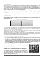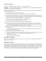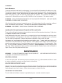
1
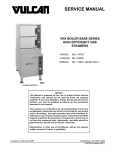
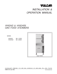
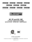
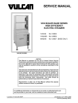
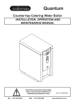
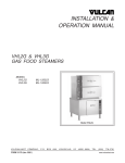
INSTALLATION &
OPERATION MANUAL
MHB24G
MODULAR GAS STEAM BOILER
MODEL
MHB24G
ML-114954
Model MHB24G
VULCAN-HART
COMPANY,
FORM 31181 (Apr. 2001)
P.O. BOX 696, LOUISVILLE, KY 40201-0696, TEL. (502) 778-2791
www.vulcanhart.com
IMPORTANT FOR YOUR SAFETY
THIS MANUAL HAS BEEN PREPARED FOR PERSONNEL QUALIFIED TO INSTALL GAS
EQUIPMENT, WHO SHOULD PERFORM THE INITIAL FIELD START-UP AND
ADJUSTMENTS OF THE EQUIPMENT COVERED BY THIS MANUAL.
POST IN A PROMINENT LOCATION THE INSTRUCTIONS TO BE FOLLOWED IN THE
EVENT THE SMELL OF GAS IS DETECTED. THIS INFORMATION CAN BE OBTAINED
FROM THE LOCAL GAS SUPPLIER.
IMPORTANT
IN THE EVENT A GAS ODOR IS DETECTED, SHUT DOWN
UNITS AT MAIN SHUTOFF VALVE AND CONTACT THE
LOCAL GAS COMPANY OR GAS SUPPLIER FOR
SERVICE.
FOR YOUR SAFETY
DO NOT STORE OR USE GASOLINE OR OTHER
FLAMMABLE VAPORS OR LIQUIDS IN THE VICINITY OF
THIS OR ANY OTHER APPLIANCE.
WARNING: IMPROPER INSTALLATION, ADJUSTMENT,
ALTERATION, SERVICE OR MAINTENANCE CAN CAUSE
PROPERTY DAMAGE, INJURY OR DEATH. READ THE
INSTALLATION, OPERATING AND MAINTENANCE
INSTRUCTIONS THOROUGHLY BEFORE INSTALLING
OR SERVICING THIS EQUIPMENT.
IN THE EVENT OF A POWER FAILURE, DO NOT ATTEMPT
TO OPERATE THIS DEVICE.
© VULCAN-HART COMPANY 1998, 2001
–2–
TABLE OF CONTENTS
GENERAL . . . . . . . . . . . . . . . . . . . . . . . . . . . . . . . . . . . . . . . . . . . . . . . . . . . . . . . . . . . . 4
INSTALLATION . . . . . . . . . . . . . . . . . . . . . . . . . . . . . . . . . . . . . . . . . . . . . . . . . . . . . . .
Unpacking . . . . . . . . . . . . . . . . . . . . . . . . . . . . . . . . . . . . . . . . . . . . . . . . . . . . . . .
Location . . . . . . . . . . . . . . . . . . . . . . . . . . . . . . . . . . . . . . . . . . . . . . . . . . . . . . . . .
Installation Codes and Standards . . . . . . . . . . . . . . . . . . . . . . . . . . . . . . . . . . . .
Leveling . . . . . . . . . . . . . . . . . . . . . . . . . . . . . . . . . . . . . . . . . . . . . . . . . . . . . . . . .
Gas Connection . . . . . . . . . . . . . . . . . . . . . . . . . . . . . . . . . . . . . . . . . . . . . . . . . . .
Testing the Gas Supply System . . . . . . . . . . . . . . . . . . . . . . . . . . . . . . . . . . . . . .
Flue Connection . . . . . . . . . . . . . . . . . . . . . . . . . . . . . . . . . . . . . . . . . . . . . . . . . .
Electrical Connection . . . . . . . . . . . . . . . . . . . . . . . . . . . . . . . . . . . . . . . . . . . . . .
Plumbing Connections . . . . . . . . . . . . . . . . . . . . . . . . . . . . . . . . . . . . . . . . . . . . .
Water Supply Connections . . . . . . . . . . . . . . . . . . . . . . . . . . . . . . . . . . . . . . . . . .
Drain Connection . . . . . . . . . . . . . . . . . . . . . . . . . . . . . . . . . . . . . . . . . . . . . . . . . .
Water Quality . . . . . . . . . . . . . . . . . . . . . . . . . . . . . . . . . . . . . . . . . . . . . . . . . . . . .
Connection of Cooking Equipment to the Boiler . . . . . . . . . . . . . . . . . . . . . . . . .
Start-up Test Run . . . . . . . . . . . . . . . . . . . . . . . . . . . . . . . . . . . . . . . . . . . . . . . . .
Automatic Blowdown . . . . . . . . . . . . . . . . . . . . . . . . . . . . . . . . . . . . . . . . . . . . . . .
Sequential Start-up . . . . . . . . . . . . . . . . . . . . . . . . . . . . . . . . . . . . . . . . . . . . . . . .
4
4
4
5
5
5
5
6
6
6
6
7
7
7
8
8
8
OPERATION . . . . . . . . . . . . . . . . . . . . . . . . . . . . . . . . . . . . . . . . . . . . . . . . . . . . . . . . . . 9
Controls — Boiler . . . . . . . . . . . . . . . . . . . . . . . . . . . . . . . . . . . . . . . . . . . . . . . . . 9
Boiler . . . . . . . . . . . . . . . . . . . . . . . . . . . . . . . . . . . . . . . . . . . . . . . . . . . . . . . . . . 10
Preheat. . . . . . . . . . . . . . . . . . . . . . . . . . . . . . . . . . . . . . . . . . . . . . . . . . . . . . . . . 10
Operating Boiler . . . . . . . . . . . . . . . . . . . . . . . . . . . . . . . . . . . . . . . . . . . . . . . . . 10
Extended Shutdown . . . . . . . . . . . . . . . . . . . . . . . . . . . . . . . . . . . . . . . . . . . . . . 10
Cleaning . . . . . . . . . . . . . . . . . . . . . . . . . . . . . . . . . . . . . . . . . . . . . . . . . . . . . . . . 11
Boiler Blowdown . . . . . . . . . . . . . . . . . . . . . . . . . . . . . . . . . . . . . . . . . . . . . . . . . 11
Guidelines for Maintaining Stainless Steel Surfaces . . . . . . . . . . . . . . . . . . . . 11
MAINTENANCE . . . . . . . . . . . . . . . . . . . . . . . . . . . . . . . . . . . . . . . . . . . . . . . . . . . . . .
Boiler Blowdown . . . . . . . . . . . . . . . . . . . . . . . . . . . . . . . . . . . . . . . . . . . . . . . . .
Boiler Pressure Relief Valve . . . . . . . . . . . . . . . . . . . . . . . . . . . . . . . . . . . . . . . .
Air Intake to the Blower . . . . . . . . . . . . . . . . . . . . . . . . . . . . . . . . . . . . . . . . . . . .
Scale Related Maintenance . . . . . . . . . . . . . . . . . . . . . . . . . . . . . . . . . . . . . . . .
Water Level Gauge . . . . . . . . . . . . . . . . . . . . . . . . . . . . . . . . . . . . . . . . . . . . . . .
Flue . . . . . . . . . . . . . . . . . . . . . . . . . . . . . . . . . . . . . . . . . . . . . . . . . . . . . . . . . . .
Boiler Inspection Plate . . . . . . . . . . . . . . . . . . . . . . . . . . . . . . . . . . . . . . . . . . . .
11
11
11
11
12
12
12
12
TROUBLESHOOTING . . . . . . . . . . . . . . . . . . . . . . . . . . . . . . . . . . . . . . . . . . . . . . . . . 12
Service and Parts Information . . . . . . . . . . . . . . . . . . . . . . . . . . . . . . . . . . . . . . . . . . . 12
–3–
Installation, Operation, and Care of
MODEL MHB24G
MODULAR GAS STEAM BOILER
KEEP THIS MANUAL FOR FUTURE USE
GENERAL
Vulcan gas steam boilers are produced with quality workmanship and material. Proper installation,
usage, and maintenance of your boiler will result in many years of satisfactory performance.
It is suggested that you thoroughly read this entire manual and carefully follow all of the instructions
provided.
The boiler can be built for natural gas or propane with gas input rating of 270,000 BTU/hr. Boiler is rated
high efficiency. Boiler output is rated 5.5 boiler horsepower (BHP), equal to approximately 190 lbs. of
steam per hour.
INSTALLATION
Before installing, verify that the electrical service and type of gas supply (natural or propane) agree with
the specifications on the rating plate located on the door of the boiler. If the supply and equipment
requirements do not agree, do not proceed with the installation. Contact your dealer or Vulcan-Hart
Company immediately.
UNPACKING
The gas steam boiler was inspected before leaving the factory. The transportation company assumes
full responsibility for safe delivery upon acceptance of the shipment. Immediately after unpacking,
check for possible shipping damage. If the boiler is found to be damaged, save the packaging material
and contact the carrier within 15 days of delivery.
LOCATION
The equipment area must be kept free and clear of combustible substances.
The gas steam boiler, when installed, must have a minimum clearance from combustible and
non-combustible construction of 6" (15.2 cm) at left and right sides and the rear. Provide adequate
clearance for servicing and proper operation: Allow 18" (45.7 cm) at left and right sides, 18" (45.7 cm) at
the rear, and 36" (91.4 cm) at the front.
An exhaust system should be located directly above the gas steam boiler to exhaust steam,
combustion gases, and heat generated by the boiler.
The gas steam boiler must be installed so that the flow of combustion and ventilation air will not be
obstructed. Make sure there is an adequate supply of air in the room to allow for combustion of the
gas at the burner. The floor area beneath the boiler must be kept free and clear.
Do not permit fans to blow directly at the gas steam boiler and avoid wall-type fans which create air
cross currents within the room. Avoid open windows next to the boiler.
–4–
INSTALLATION CODES AND STANDARDS
In the United States, the Vulcan gas steam boiler must be installed in accordance with: 1) State and
local codes; 2) National Fuel Gas Code, ANSI-Z223.1 (latest edition), available from American Gas
Association, 1515 Wilson Boulevard, Arlington, VA 22209; 3) NFPA-96, Vapor Removal from Cooking
Equipment; and 4) National Electrical Code, NFPA-70 (latest edition), available from National Fire
Protection Association, Batterymarch Park, Quincy, MA 02269.
In Canada, the gas steam boiler must be installed in accordance with: 1) Local codes; 2) CAN/CGAB149.1, Natural Gas Installation Code (latest edition) or CAN/CGA-B149.2, Propane Installation Code,
(latest edition) available from Canadian Standards Association, 178 Rexdale Boulevard, Etobicoke,
Ontario, Canada M9W 1R3; and 3) Canadian Electrical Code, CSA C22.2 No. 3, Electrical Features
of Fuel Burning Equipment (latest edition).
LEVELING
Use a spirit level to adjust the feet to level the gas steam boiler left-to-right and front-to-back.
GAS CONNECTION
Gas supply connections and any pipe joint compound must be resistant to the action of propane gases.
A 1" (2.5 cm) minimum inside diameter gas supply line is recommended. Connect the gas supply to the
gas valve using a 1" to 3⁄4" (1.9 cm) reducer. Make sure the pipes are clean and free of obstructions.
Codes require that a gas shutoff valve must be installed in the gas line ahead of the boiler.
The burner is equipped with fixed gas and air orifices for use with natural or propane gas.
The gas line must be capable of delivering gas to the boiler without excessive pressure drop at the rate
specified on the rating plate.
The boiler is equipped with a factory preset pressure regulator. No further adjustment should be
required.
Gas Type
Natural
Propane
Line Pressure
Min.
Max.
Manifold
Pressure
Pilot
Pressure
7" W.C.
14" W.C.
3.0" W.C.
3.5" W.C.
(1.75 kPa)
(3.5 kPa)
(.75 kPa)
(.88 kPa)
11" W.C.
14" W.C.
3.0" W.C.
3.5" W.C.
(2.7 kPa)
(3.5 kPa)
(.75 kPa)
(.88 kPa)
WARNING: PRIOR TO LIGHTING, CHECK ALL JOINTS IN THE GAS SUPPLY LINE FOR LEAKS.
USE SOAP AND WATER SOLUTION. DO NOT USE AN OPEN FLAME.
After piping has been checked for leaks, all piping receiving gas should be fully purged to remove air.
TESTING THE GAS SUPPLY SYSTEM
When gas supply pressure exceeds 1⁄2 psig (3.45 kPa), the gas steam boiler and its individual shutoff
valve must be disconnected from the gas supply piping system.
When gas supply pressure is 1⁄2 psig (3.45 kPa) or less, the gas steam boiler should be isolated from the
gas supply system by closing its individual manual shutoff valve.
–5–
FLUE CONNECTION
DO NOT obstruct the flow of flue gases from the flue located on the rear of the gas steam boiler.
It is recommended that the flue gases be ventilated to the outside of the building through a ventilation
system installed by qualified personnel.
A minimum clearance of 18" (45.7 cm) must be maintained from the termination of the flue to the filters
of the hood venting system.
Information on the construction and installation of ventilating hoods may be obtained from the standard
for Vapor Removal from Cooking Equipment, NFPA No. 96 (latest edition), available from National Fire
Protection Association, Batterymarch Park, Quincy, MA 02269.
ELECTRICAL CONNECTION
WARNING: ELECTRICAL AND GROUNDING CONNECTIONS MUST COMPLY WITH THE
APPLICABLE PORTIONS OF THE NATIONAL ELECTRICAL CODE AND/OR OTHER LOCAL
ELECTRICAL CODES.
WARNING: DISCONNECT ELECTRICAL POWER SUPPLY AND PLACE A TAG AT THE
DISCONNECT SWITCH TO INDICATE YOU ARE WORKING ON THE CIRCUIT.
ELECTRICAL DATA
Model
Volts / Hertz / Phase
Machine Amps
Minimum Circuit Ampacity
Maximum Protective Device
AMPS
MHB24G
120 / 60 / 1
3.0
15
Compiled in accordance with the National Electrical Code, NFPA-70 (latest edition).
Connect the electrical supply circuit to the terminal block located in the boiler control box. A 7/8"
diameter hole for 1/2" trade size conduit is provided on the side of the control box. Use copper wire
suitable for at least 75°C. A grounding wire must be connected to the ground lug. If a cord and plug
is to be used, provide suitable durable cord, molded plug, and a proper strain relief.
The wiring diagram is located on the door of the boiler.
Do not connect the boiler to electrical supply until after gas connections have been made.
PLUMBING CONNECTIONS
WARNING: PLUMBING CONNECTIONS MUST COMPLY WITH APPLICABLE SANITARY, SAFETY,
AND PLUMBING CODES.
Water Supply Connections
Two cold water supplies are recommended. Treated water may be required to fill the boiler; untreated
water may be used for the cold water condenser on the boiler blowdown line.
•
Connect cold water supply to the 1⁄2" NPT (1.27 cm) fill water connection. Water treatment may be
needed — refer to Water Quality, page 7. Water pressure of 20 – 80 psig is required.
•
Connect cold water supply to the 1⁄8" NPT (0.3175 cm) cold water condenser connection (treatment
is not needed). Water pressure of 20 – 80 psig is required.
–6–
Drain Connection
The 11/4" NPT (3.175 cm) threaded fitting on the condenser box must be extended to an open, air gap
type drain, with maximum length of 12 inches (30.5 cm) to the open drain. Do not reduce the 11/4"
(3.175 cm) drain piping throughout its length. Provide a suitable floor sink with a minimum depth of 12
inches (30.5 cm). The floor sink is NOT to be directly under the boiler and should be at a distance so
that steam vapors will not enter the boiler from underneath.
Drain pipe should be either iron or copper. DO NOT use PVC pipe — PVC pipe may lose its rigidity
or glue may fail.
CAUTION: In order to avoid any back pressure in the boiler, do not connect solidly to any drain
connection.
WATER QUALITY
Before connecting the gas steam boiler to water, the water supply should be analyzed to make sure
specifications are met.
WATER QUALITY SPECIFICATIONS
Total Disolved Solids (TDS)*
Less than 60 ppm
Total Alkalinity
Less than 20 ppm
Silica
Less than 13 ppm
Chloride
Less than 30 ppm
pH
7.0 to 8.0
*17.1 ppm = 1 grain of hardness
If the water supply fails to meet these specifications, it will be necessary to install a water conditioner
on the boiler cold water supply line. APPLIANCE FAILURE CAUSED BY INADEQUATE WATER
QUALITY IS NOT COVERED UNDER WARRANTY.
Water supplies vary from one location to another. A local water treatment specialist should be
consulted before installing any boiler or water conditioner.
Untreated water contains scale producing minerals which can precipitate onto the surfaces in the
boiler. Due to the temperatures in the boiler, the minerals can bake onto the surfaces and components.
This can result in early component failure and reduced product life.
Mineral scale on components causes several problems:
1. The surface of the boiler becomes coated with scale, reducing the heat transfer efficiency. This can
produce hot spots on the boiler and result in premature failure.
2. The water level probes become coated with scale. Scale will bridge across the probe insulator from
the metal extension which senses the water level in the boiler. Once this scale becomes wet, the
water level control is unable to maintain the proper water level in the boiler. This situation may
cause the boiler to fail if the boiler is not adequately covered by water.
Strainers or filters will NOT remove minerals from the water.
Sensors in the boiler use ions in the water to detect the water level.
Do not use distilled (fully demineralized or de-ionized) water. This
could provide a false reading.
STEAM LINE CONNECTION
CONNECTION OF COOKING EQUIPMENT TO THE BOILER
The connection point for the steam line to other equipment is a 3/4"
NPT female fitting on the left side of the boiler near the top and
towards the rear. Remove the 3/4" NPT pipe plug (Fig. 1) and use the
Piping Kit available from Vulcan-Hart.
–7–
PL-41531-1
Fig. 1
START-UP TEST RUN
Refer to the OPERATION section, pages 9 – 11 for more information.
WARNING: THE GAS STEAM BOILER AND ITS PARTS ARE HOT.
CLEANING, OR SERVICING THE BOILER.
USE CARE WHEN OPERATING,
After the gas steam boiler is installed and proper service connections have been made, thoroughly test
the boiler before operation.
1. Turn knob of gas valve counterclockwise to on.
2. Be sure the water inlet valve is open. Close only for service or long shutdown.
3. Locate the power switch and press [ I ] to start. Two indicator lights (Low Water and High Pressure)
become lit as water fills the boiler. After about 4 – 5 minutes, the water will reach the required level
in the boiler and the green indicator light on the reset switch is lit.
4. Observe the water level gauge sight glass to verify the water level.
• Keep both valves on the water gauge open at all times.
5. Press the reset switch with green indicator light lit to light the boiler.
6. Both Low Water and High Pressure indicator lights must be off before the burner will ignite.
• If the indicator lights do not go off after 15 minutes or if they come on during normal operation,
press [ 0 ] for off and contact an authorized Vulcan-Hart servicer.
7. If the burner does not ignite after 30 seconds press [ 0 ] on the power switch for off, wait 5 minutes,
then repeat steps 1 – 5.
• If the ignition does not occur after 3 tries, press [ 0 ] on the power switch for off and contact an
authorized Vulcan-Hart servicer.
8. Steam generation will begin in about 10 minutes.
• Observe that the boiler pressure gauge indicates steam pressure in the range of 8 – 12 psig.
9. To shut down the boiler, press [ 0 ] on the power switch on the boiler (Fig. 2).
• Indicator lights are not lit.
• Boiler will automatically blow down.
AUTOMATIC BLOWDOWN
When [ 0 ] on the power switch on the boiler (Fig. 1) is pressed, the boiler will blow down for
approximately 5 minutes.
SEQUENTIAL START-UP
After the boiler is operating and producing steam, start-up the farthest away piece of equipment until
it is preheated and 'up-to-temperature' before starting the next piece of equipment. It is recommended
that all kettles be started before any compartment steamers. This will allow the largest pieces or the
most difficult to warm up equipment to be properly warmed up before smaller, nearer units which
require less heat. This will pervent the system from being overwhelmed by initial demand.
–8–
OPERATION
WARNING: THE GAS STEAM BOILER AND ITS PARTS ARE HOT.
CLEANING, OR SERVICING THE BOILER.
USE CARE WHEN OPERATING,
CONTROLS — BOILER (Figs. 2, 3)
Power Switch
POWER
SWITCH
HIGH
PRESSURE
LIGHT
• Press [ I ] to begin filling the boiler.
• Press [ 0 ] to turn the boiler off (automatic
blow down will occur).
LOW
WATER
LIGHT
High Pressure Light
RESET SWITCH
(GREEN)
• Is lit after [ I ] is pressed and stays on during fill.
Goes off after reset switch is pressed (when
green light is lit).
• Is lit if pressure exceeds 15 psig.
WATER
LEVEL
GAUGE
Low Water Light
• Is lit after [ I ] is pressed and stays on until reset
switch is pressed (when green light is lit).
• Is lit if water level is too low.
Reset Switch
• Press the reset switch (when green light is lit)
to ignite the burner after water has reached the
required level.
BOILER
PRESSURE
GAUGE
Boiler Pressure Gauge
• Indicates the boiler steam pressure; the normal
operating range is 8 – 12 psig.
PL-41513-1
Fig. 2
Water Level Gauge
• The correct water level is one inch of water in the water level gauge sight glass.
• The manual valves at the top and bottom of the water level gauge (Fig. 3) must be fully open
(counterclockwise).
• Observe that the water is clean and clear in the glass tube.
- The appearance of extreme murkiness in the water indicates inadequate water quality and will
cause the controls and the boiler to fail. Warranty does not cover malfunction due to poor water
conditions.
–9–
BOILER (Fig. 3)
PRESSURE RELIEF VALVE
GAS VALVE
PROBE HOUSING
BLOWDOWN VALVE
WATER INLET VALVE
MANUAL VALVES
WATER LEVEL GAUGE
Fig. 3
PL-41514-1
Pressure Relief Valve
• The pressure relief valve located on the top left side prevents pressure in the boiler from exceeding
15 psig.
• Manually pull up the lever daily to reduce scale buildup and verify that the pressure relief valve
functions properly.
Gas Valve
• Located behind the door. Turn counterclockwise to on; clockwise to off.
Probe Housing Blowdown Valve
• Open periodically (monthly) to blow down the probes and remove sediment and scale buildup.
• Located toward the back left side, wait until the boiler is cool before opening valve.
Water Inlet Valve
• Located toward the bottom center in the boiler, turn the valve off to shut off the water supply.
PREHEAT
This should be done when the gas steam boiler is first used for the day.
OPERATING BOILER
1. Press [ I ] and wait until boiler is filled to the required level. Both the Low Water and High Pressure
indicator lights are lit.
2. When the green indicator light is lit, press the Reset Switch. Both the Low Water and High Pressure
indicator lights must go off before the burner will ignite.
3. Wait 10 minutes for boiler to generate steam.
EXTENDED SHUTDOWN
To shut down for an extended period:
1. Press [ 0 ] on power switch (Fig. 2).
2. Turn knob of gas valve clockwise to off.
3. Close the water inlet valve.
– 10 –
CLEANING
Boiler Blowdown
To prevent malfunction of controls and clogging, it is essential to flush (blow down) the boiler every day.
This will flush out any accumulated minerals (left from the feed water) and aid in preventing internal
scale build-up which, in time, would interfere with proper boiler operation. Failure to blow down the
boiler every day may void the warranty applying to the controls. The presence of minerals in
suspension is indicated by a murky or milky condition in the first portion of the water drained.
WARNING: THE WATER BEING DRAINED IS HOT AND UNDER PRESSURE. USE CARE WHEN
CLEANING OR SERVICING THE BOILER.
After the boiler boiler has been in operation, press [ 0 ] to blow down the boiler removing sediment,
scale, or lime build-up in the boiler. The boiler will blow down for approximately 5 minutes.
WARNING: DISCONNECT ELECTRICAL POWER BEFORE CLEANING.
GUIDELINES FOR MAINTAINING STAINLESS STEEL SURFACES
There are three things that can break down stainless steel and allow corrosion to develop: 1) Abrasion;
2) Deposits and water; and 3) Chlorides.
Avoid rubbing with steel pads, wire brushes, or scrapers that can leave iron deposits on stainless steel;
instead, use plastic scouring pads or soft cloths. For stubborn stains, use products such as Cameo,
Talc, or Zud First Impression. Always rub parallel to the polish lines or with the grain.
Hard water can leave deposits that promote rust on stainless steel. Treated water from softeners or
certain filters can eliminate these mineral deposits. Other deposits from food or lubrication must be
properly removed by cleaning. Use mild detergent and non-chloride cleaners. Rinse thoroughly. Wipe
dry. If using chloride containing cleaners or sanitizers, rinse repeatedly to avoid stainless steel
corrosion. Where appropriate, apply a polish recommended for stainless steel (such as Benefit or
Super Sheen) for extra protection and lustre.
MAINTENANCE
WARNING: THE GAS STEAM BOILER AND ITS PARTS ARE HOT.
CLEANING, OR SERVICING THE BOILER.
USE CARE WHEN OPERATING,
BOILER BLOWDOWN
At least once daily after the boiler has been in operation, press [ 0 ] to blow down the boiler in order
to remove sediments, scalants, and lime build-up in the boiler.
BOILER PRESSURE RELIEF VALVE
At least once every day, check the pressure relief valve (set to open at 15 psi) to see that it is functioning
properly. The valve is located on the top left side of the boiler. Trip the pressure relief valve when the
steam gauge shows 4 psi or above. When steam escapes, release the valve.
AIR INTAKE TO THE BLOWER
The air intake to the blower needs to be periodically (once a month) cleaned or wiped.
– 11 –
SCALE RELATED MAINTENANCE
Periodic maintenance is necessary to keep your boiler clean and efficient. It is recommended that
initially after three months of boiler usage you have your Vulcan Hart authorized servicer inspect the
boiler and perform the below listed maintenance and inspections. Local water conditions and steamer
usage will determine the frequency that this service must be repeated; however, a minimum
recommendation is once a year. This maintenance is not covered by warranty.
• Descaler — Automatic descalers are provided inside the boiler to hold minerals in a suspended state
so they can be flushed out. This descaler will be consumed. The rate of consumption depends upon
the chemical makeup of the feed water and the average volume of feed water required. An inspection
by service personnel is recommended until it is learned from experience what the normal life of the
descalers are under your operating conditions.
• Boiler Scale — Have the servicer inspect the boiler through the hand hole for lime build-up. Have
your servicer open the washout plug under the boiler and add water to flush out any loose scale.
If a build-up of scale is present that indicates the boiler should be delimed, have the servicer delime
the boiler at this time. If a water treatment system that has its own delime procedure is being used,
follow the procedures provided with the water treatment system.
• Boiler Drain Valve Strainer — Have your servicer clean the strainer screen as needed.
• Water Level Probes — Have your servicer inspect and clean the water level probes in the boiler.
WATER LEVEL GAUGE
Check the water level gauge sight glass daily. The correct water level is approximately one inch of
water in the water level gauge sight glass.
Extremely murky water in the sight glass indicates bad water conditions. The boiler should be blown
down. If conditions persist, have the boiler cleaned by your local Vulcan-Hart servicer.
FLUE
Annually, when the boiler is cool, check the flue and clear any obstructions.
BOILER INSPECTION PLATE
The plate must be removed for boiler inspection every 12 months according to state code. This must
be done by a boiler inspector.
TROUBLESHOOTING
PROBLEM
POSSIBLE CAUSE
POSSIBLE REMEDY
Boiler will not fill.
Boiler's power and water supply
are off.
Check that power and water supply
are ON.
Boiler will not heat or build
pressure.
Gas supply is off.
Check that gas supply is ON. Refer
to Start-Up Test Run, page 8.
SERVICE AND PARTS INFORMATION
To obtain service and parts information concerning this boiler, contact the Vulcan-Hart Service Agency
in your area (refer to listing supplied with the boiler), or Vulcan-Hart Company Service Department at
the address or phone number shown on the front cover of this manual.
FORM 31181 (Apr. 2001)
– 12 –
PRINTED IN U.S.A.