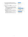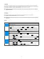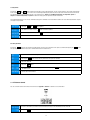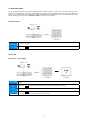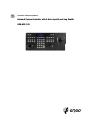
1
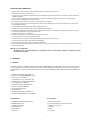
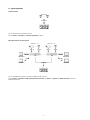
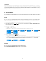
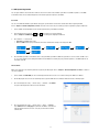
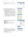
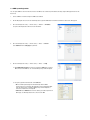
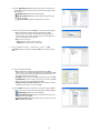
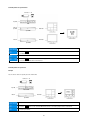
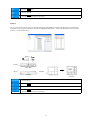
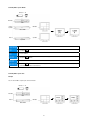
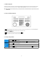
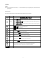
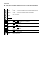
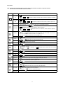
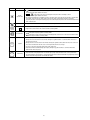
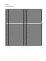
Installation and Operating Manual
Network System Controller with 3-Axis Joystick and Jog Shuttle
KBD-NSC-100
Contents
Safety Instructions / Maintenance..............................................................................................................................................................................................3
1.
Introduction....................................................................................................................................................................................................................3
1.1 Features...............................................................................................................................................................................................................3
1.2 Typical Applications..............................................................................................................................................................................................4
1.3 Rear Panel............................................................................................................................................................................................................7
1.4 Bottom Panel........................................................................................................................................................................................................8
1.5 Top Panel..............................................................................................................................................................................................................9
2.
Installation....................................................................................................................................................................................................................10
2.1 PTZ Camera Registration....................................................................................................................................................................................10
2.2 DVR System Registration....................................................................................................................................................................................11
2.3 MMX System Registration...................................................................................................................................................................................13
3.
Operation......................................................................................................................................................................................................................16
3.1 Overview............................................................................................................................................................................................................16
3.2 PTZ Camera Control............................................................................................................................................................................................17
3.3 DVR System Control............................................................................................................................................................................................18
3.4 MMX System Control..........................................................................................................................................................................................19
4.
LCD Menu Configuration...............................................................................................................................................................................................24
4.1 Buttons for LCD Menu Configuration...................................................................................................................................................................24
4.2 Entering or Exiting LCD Menu..............................................................................................................................................................................24
4.3 Setup Menu........................................................................................................................................................................................................25
5.
Remote Configuration...................................................................................................................................................................................................26
5.1 System...............................................................................................................................................................................................................26
5.2 Network..............................................................................................................................................................................................................28
5.3 Device................................................................................................................................................................................................................29
5.4 Function.............................................................................................................................................................................................................31
6.
Troubleshooting............................................................................................................................................................................................................32
7.
Technical Specifications................................................................................................................................................................................................33
APPENDIX 1 – RS-485 Connector Pin Outs...............................................................................................................................................................................34
APPENDIX 2 – Buttons.............................................................................................................................................................................................................35
APPENDIX 3 – PTZ Camera Model Number..............................................................................................................................................................................39
APPENDIX 4 – System Upgrade Error Code..............................................................................................................................................................................40
APPENDIX 5 – Map of Screens (Remote Setup)........................................................................................................................................................................40
Montage- und Betriebsanleitung
Installation and Operating Instructions
Mode d’emploi
Instrucciones de manejo
⇒
www.videor.com
Safety Instructions / Maintenance
• Read these safety instructions and the operation manual first before you install and commission the unit.
• Keep the manual in a safe place for later reference.
• The system may only be commissioned and maintained by personnel authorized to do this and it must only be carried out in accordance with relevant
standards and guidelines.
•Protect your unit from contamination with water and humidity to prevent it from permanent damage. Never switch the unit on when it gets wet.
Have it checked at an authorized service center in this case.
• Never operate the units outside of the specifications as this may prevent their functioning.
•Do not operate the unit beyond their specified temperature, humidity or power ratings. Operate the unit only at a temperature range of 0°C to +50°C
and at a humidity of max. 80%.
• The unit should be protected against excessive heat, dust, damp and vibration.
• To disconnect the power cord of the unit, pull it out by the plug. Never pull the cord itself.
•Pay attention when laying the connection cable and observe that the cable is not subject to heavy loads, kinks, or damage and no moisture can get in.
Do not attempt to disassemble the camera board from the dome.
• Contact your local dealer in case of malfunction.
• Maintenance and repair have to be carried out only by authorized service centers.
Before opening the cover disconnect the unit from mains input.
• The warranty becomes void if repairs are undertaken by unauthorized persons. Do not open the housing.
• The connection cable should only be changed by Videor E. Hartig GmbH.
• Only use original parts and original accessories from Videor E. Hartig GmbH.
•Do not use strong or abrasive detergents when cleaning the dome. Use a dry cloth to clean the dome surface. In case the dirt is hard to remove, use a mild
detergent and wipe gently.
NOTE: T his is a class A digital device.
This digital device can cause harmful interference in a residential area; in this case the user may be required to take appropriate corrective
action at his/her own expense.
1. Introduction
1.1 Features
This network keyboard controls Multifunctional Network Matrix Switchers (MMXs), Digital Video Recorders (DVRs), network video transmitters, network video
receivers and network cameras remotely via network connection. Also, the network keyboard controls DVRs and PTZ cameras connected to the network
keyboard via RS-485 connection. The network keyboard can be accessed, configured and managed by using the INIT (Integrated Network Installation Tool)
program.
• Hybrid Remote Keyboard (IP & Analog Devices)
• Multi Device Control (PTZ/DVR/MMX/NMS/Server,etc.)
• Macro Function (up to 100 Macros)
• Programmable Presets, Tours, Patterns and others
• Separable Joystick for Left&Right-handed Operators
• Function Mapping (up to 8 Functions)
• Easy Firmware Upgrade by USB and Network
• Built-in 2 Lines Character LCD Display
• Two-way Audio Communication
•2x USB 2.0 Interface
• Integrated Web Server: 10Base-T/100Base-TX
• RS-485: 2x Half-Duplex Communication (PTZ & DVR)
Compatible Devices
Package Contents
• MMX (Multifunctional Network Matrix Switcher)
• Network System Controller
• DVR (Digital Video Recorder)
• Joystick (Removable) and Joystick connecting cable
• Network Video Transmitter
• Adaptor and accessory pack
• Network Video Receiver
• Power Cord
• Network Camera
• INIT CD
• PTZ Camera
• User’s Manual
1.2 Typical Applications
PTZ Camera Control
PTZ Cameras
RS485 PTZ
Network Keyboard
You can control PTZ cameras via RS-485 connection.
Refer to Chapter 2 – Installation, 2.1 PTZ Camera Registration for details.
DVR System Control via RS-485 Connection
Cameras 1 ~ 16
Cameras 1 ~ 16
Video In
Video Out
Main Monitor
RS-485
Video In
DVR
DVR
Spot Out
Spot Monitor
RS-485
Video Out
Main Monitor
Spot Out
RS485 DVR
Spot Monitor
Network Keyboard
You can control DVRs and PTZ cameras connected to the DVRs via RS-485 connection.
Refer to Chapter 2 – Installation, 2.2 DVR System Registration, Basic Mode and Chapter 3 – Operation, 3.3 DVR System Control for details on
installation and operation.
DVR System Control via Network Connection
Cameras 1 ~ 16
Video In
Video Out
Main Monitor
Cameras 1 ~ 16
RS-485
Video In
DVR
RS-485
DVR
Video Out
Main Monitor
Spot Out
Spot Out
Spot Monitor
Spot Monitor
Network Keyboard
You can control DVRs and PTZ cameras connected to the DVRs via network connection.
Refer to Chapter 2 – Installation, 2.2 DVR System Registration, Advanced Mode and Chapter 3 – Operation, 3.3 DVR System Control for details.
MMX System Control
Cameras 1 ~ 16
Cameras 17 ~ 32
Cameras 225 ~ 240
DVR 1
DVR 2
DVR 15
16 Loop Out
16 Loop Out
16 Loop Out
Master MMX [0]
Slave MMX [1]
Slave MMX [14]
Slave MMX [15]
1 Main Out
4 Quad Out
4 Quad Out
4 Quad Out
Quad Monitor
Quad Monitor
15x1
Main Out
16x4
Spot Out
Quad Monitor
Main Monitor
Network Keyboard
Spot MMX [0]
Spot MMX [1]
Spot MMX [2]
Spot MMX [3]
1 Spot Out
1 Spot Out
1 Spot Out
1 Spot Out
Spot Monitor 1
Spot Monitor 2
Spot Monitor 3
Spot Monitor 4
Network Keyboard
Network Keyboard
Network Keyboard
Network Keyboard
You can control MMXs, DVRs connected to the MMX and PTZ cameras connected to the DVRs via network connection.
Refer to Chapter 2 – Installation, 2.4 MMX System Registration and Chapter 3 – Operation, 3.5 MMX System Control for details.
1.3 Rear Panel
No.
Designation
Details
1
Speaker
Connect to an amplifier (Line-out). The network keyboard does not have amplified audio output, so you will need a speaker
with an amplifier. Audio surveillance may be prohibited by laws that vary by region. Check the laws in your area before using
this product for surveillance purposes.
2
MIC
Connect to an audio source. (Line-in or Microphone)
3
USB Port
Connect a USB flash drive to upgrade the software. See below for details.
4
Network Port
Connect a UTP Cat5 cable with an RJ-45 jack.
Refer to Chapter 5 – Remote Configuration and the INIT User’s Manual for details on network setup.
5
RS485
Connect to PTZ cameras. Connect TX+/RX+ and TX-/RX- of the PTZ camera to the + and – (respectively) of the network
keyboard. Refer to the PTZ camera manufacturer’s manual for configuring the RS-485 connection.
PTZ Port
6
RS485
DVR Port
Connect to DVRs. Connect TX+/RX+ and TX-/RX- of the DVR to the + and – (respectively) of the network keyboard.
Refer to the DVR User’s Manual for configuring the RS-485 connection.
7
Power In
Connect the power adaptor provided with the network keyboard to the network keyboard. The network keyboard starts booting
as soon as power is applied.
8
Joystick Port
Connect a joystick cable. A joystick cable should be connected while the network keyboard is powered down.
CAUTIONS:
• The network connector is not designed to be connected directly with cable or wire intended for outdoor use.
• Do NOT connect or disconnect the joystick cable while the network keyboard is powered up. The network keyboard must be powered down to
connect or disconnect the joystick cable; otherwise, it might cause damage or malfunction on the network keyboard.
WARNING:
ROUTE POWER CORDS SO THAT THEY ARE NOT A TRIPPING HAZARD. MAKE CERTAIN THE POWER CORD WILL NOT BE PINCHED OR ABRADED BY
FURNITURE. DO NOT INSTALL POWER CORDS UNDER RUGS OR CARPET. THE POWER CORD HAS A GROUNDING PIN. IF YOUR POWER OUTLET DOES
NOT HAVE A GROUNDING PIN RECEPTACLE, DO NOT MODIFY THE PLUG. DO NOT OVERLOAD THE CIRCUIT BY PLUGGING TOO MANY DEVICES INTO ONE
CIRCUIT
Software Upgrade
Connect a USB flash drive to upgrade the software. Create a text file named as autorun.txt and enter the name of the upgrade file including a file extension
(.rui). –> Connect a USB flash drive containing the upgrade file and the autorun.txt file to the network keyboard. –> Enter the LCD menu. –> Go to the
General then to the Upgrade menu. Selecting Upgrade and then Yes makes the network keyboard load the upgrade file of the name saved in the autorun.txt
file and perform upgrade automatically. –> The network keyboard restarts. –> The LCD default screen is displayed after completing upgrade. When an error
occurs during the software upgrade, refer to Appendix 4 – System Upgrade Error Code for details.
You can upgrade the software remotely by running the INIT program. Refer to the INIT User’s Manual for details on remote software upgrade.
1.4 Bottom Panel
No.
Designation
Details
1
Joystick Bracket
Use to attach the joystick provided with the network keyboard body to the network keyboard body.
The joystick can be attached either to the left or to the right of the network keyboard body.
2
Factory Reset
Switch
Returns all settings to the original factory settings. Refer to Factory Reset for details.
3
Joystick
Connect a joystick cable. A joystick cable should be connected while the network keyboard is powered down.
Input Port
4
RS485 DVR
Termination (1)
Set the switch to ON if RS-485 communication environment is not good and the connection is not made when controlling a
DVR via RS-485 connection.
5
RS485 PTZ
Termination (2)
Set the switch to ON if RS-485 communication environment is not good and the connection is not made when controlling a
PTZ camera via RS-485 connection.
CAUTION: Do NOT connect or disconnect the joystick cable while the network keyboard is powered up. The network keyboard must be powered
down to connect or disconnect the joystick cable; otherwise, it might cause damage or malfunction on the network keyboard.
Factory Reset
CAUTION: When performing a Factory Reset, you will lose any settings you have saved.
You can perform a factory reset while the network keyboard is turned on. Poke a straightened paperclip into the factory reset switch hole and hold the switch
for about three seconds. Releasing the reset switch performs factory reset. A factory reset also can be performed remotely by running the INIT program.
The network keyboard restarts after completing the factory reset. Refer to INIT User’s Manual for details on remote factory resetting.
1.5 Top Panel
No.
Designation
Details
1
Joystick
Controls pan and tilt of a PTZ camera by using the stick or zoom of a PTZ camera by using the shuttle ring.
2
PTZ Camera
Control Buttons
Controls the PTZ camera by setting up presets or expanded PTZ features.
Refer to Appendix 2 – Buttons, PTZ Camera Control for details.
3
LCD Screen
Displays operation commands or LCD menus.
Refer to Chapter 3 – Operation and Chapter 4 – LCD Menu Configuration for details.
4
Device Control
Buttons
Controls remote devices including DVRs. Refer to Appendix 2 – Buttons, Device Control for details.
5
Arrow Buttons
Allows you to navigate through setup menus or adjust number’s value during the configuration.
6
Enter Button
Selects an item or completes an entry that you have made during the configuration of the network keyboard or devices.
7
Command
Buttons
Gives commands. Refer to Appendix 2 – Buttons, Operation Command for details.
8
Jog Dial
Functions only when controlling a DVR. Refer to Appendix 2 – Buttons, Device Control for details.
9
Shuttle Ring
Functions only when controlling a DVR. Refer to Appendix 2 – Buttons, Device Control for details.
2. Installation
A device should be registered on the network keyboard properly for control by a network keyboard. The Basic mode and Advanced mode are supported for
registration and control of the device, and the device is controllable only in the mode which the device is registered on. When controlling devices via RS-485
connection only, you can register the devices in the Basic mode or in the Advanced mode. When controlling devices via network and RS-485 connections, you
can register the devices in the Advanced mode only. Both the LCD menu and the INIT program are available for the registration in the Basic mode, and only
the INIT program is available for the registration in the Advanced mode.
2.1 PTZ Camera Registration
You can register PTZ cameras to control via RS-485 connection. The control of PTZ cameras with different port information is supported only in the Advanced
mode.
Basic Mode
PTZ cameras can be registered on the network keyboard in the Basic mode locally by using the LCD menus or remotely by using the INIT program. Refer to
Chapter 5 – Remote Configuration, 5.3 Device for details on the remote registration. The following is about the registration by using the LCD menus.
1. Connect a PTZ camera to RS485 PTZ port of the network keyboard referring to the PTZ camera’s User’s Manual.
2. Enter the LCD menu by pressing the
and
details on entering and configuring the LCD menu.
button together of the network keyboard. Refer to Chapter 4 – LCD Menu Configuration for
3. Go to the Device –> General menu.
• Setup Type: Select Basic (Basic mode).
• Port: Select PTZ and set up port information for RS-485 communication referring to the settings on the PTZ camera.
4. Return to the Setup menu by pressing the
button.
• Number of CAMs: Enter the number of cameras connected to the network keyboard.
• 485ID, Model: Set up the RS-485 ID and model number of the PTZ camera for RS-485 communication. The RS-485 ID will be used to distinguish
the camera from other cameras when controlling it by using a network keyboard, so each camera should have its own unique RS-485 ID.
Refer to Appendix 3 – PTZ Camera Model Number for details on the model number of each PTZ camera.
Advanced Mode
PTZ cameras can be registered on the network keyboard remotely by using the INIT program.
Refer to Chapter 5 – Remote Configuration, 5.3 Device for details on the remote registration.
10
2.2 DVR System Registration
You can register a DVR to control via RS-485 or network connection. In the Basic mode, the DVR’s system ID set in each DVR is required to control DVRs.
In the Advanced mode, the user-defined ID registered on the network keyboard is required to control DVRs.
Basic Mode
You can control a DVR with the DVR’s system ID after setting up the port information for the RS-485 communication without registering the DVR.
Refer to Chapter 5 – Remote Configuration, 5.3 Device for details on the remote setup. The following is about the registration by using the LCD menus.
1. Connect a DVR to the RS-485 DVR port of the network keyboard referring to the DVR’s User’s Manual.
2. Enter the LCD menu by pressing the
and
button together of the network keyboard.
Refer to Chapter 4 – LCD Menu Configuration for details on entering and configuring the LCD menu.
3. Go to the Device –> General menu.
• Setup Type: Select Basic (Basic mode)
• Port: Select DVR and set up the port information for RS-485 communication referring to the settings in the DVR.
4. Check the DVR’s system ID set in the DVR. You have to change the DVR’s system ID in the DVR if the system ID is in use in more than one DVR or set to
„0.” The system ID will be used to distinguish the DVR from other DVRs when controlling it by using a network keyboard, so each DVR should have its
own unique system ID.
Advanced Mode
DVRs can be registered on the network keyboard remotely by using the INIT program. Refer to Chapter 5 – Remote Configuration, 5.3 Device for details on
the remote registration.
1. Connect a DVR to the RS485 DVR port of the network keyboard via RS-485 connection or to a network referring to the DVR’s User’s Manual.
2. Run the INIT program and connect to the network keyboard to register the DVR. Refer to the INIT User’s Manual for details on the INIT program.
3. Go to the following menus: Setup –> Remote Setup – > Network –> IP Address
Set up the network keyboard’s network connection information.
4. Go to the following menus: Setup –> Remote Setup –> Device –> General
Select Advanced from the Setup Type drop-down list. If the DVR is connected to the
network keyboard via RS-485 connection, set up the port information for RS-485
communication.
11
5. Go to the following menus: Setup –> Remote Setup –> Device –> Setup
5.1.Click Digital Video Recorder in the device list, and then the Add button to register
the DVR.
5.2.Set up the registration information and click the OK button.
• ID: The network keyboard assigns the ID automatically when the DVR is
registered, and you can change the ID. The ID will be used to distinguish the DVR
from other devices when controlling the DVR by using a network keyboard, so
each device should have its own unique ID.
• Connection: Select RS-485 or Ethernet depending on the connection type.
− RS485: Enter the DVR’s system ID set in the DVR if the DVR is connected to the
network keyboard via RS-485 connection. You have to change the DVR’s
system ID in the DVR if the system ID is in use in more than one DVR or set to
„0.” The system ID will be used to distinguish the DVR from other DVRs when
controlling it by using a network keyboard, so each DVR should have its own
unique system ID.
− Ethernet: Enter the IP address, port numbers (Control Port: Watch port), user
ID and password for the connection to the DVR if the DVR is connected to a
network. The user ID and password is for the connection to the DVR and you
can use any user ID and password registered on the DVR. It is required to
log in a user with the authority over the function to control depending on the
function when controlling the DVR.
5.3.Click the Digital Video Recorder pull-down menu in the device list, and then the
registered DVR’s pull-down menu. A list of monitors and cameras supported in the
DVR is displayed.
•
[ID] Main Monitor: Displays the monitor ID and type.
•
[ID] Spot Monitor No.: Displays the monitor ID, monitor type and the Spot
Out number of the DVR.
•
[ID] „Camera Name”: Displays the ID and name of the camera.
5.4.Click a monitor or a camera in the list, and then the Edit button. Set up the monitor
or camera information.
• ID: The network keyboard assigns the ID automatically when the DVR is
registered, and you can change the ID. The ID will be used to distinguish the
monitor or camera from other monitors or cameras when controlling it by using a
network keyboard, so each monitor or camera should have its own unique ID.
• Type: Set up the camera type.
− Fixed: Select if the camera is not a PTZ camera.
− PTZ Camera: Select if the camera is a PTZ camera.
12
2.3 MMX System Registration
You can register MMXs to control via network connection. The MMX can be controlled only in the Advanced mode by using the INIT program and not in the
Basic mode.
1. Connect a MMX to a network referring to the MMX’s User’s Manual.
2. Run the INIT program and connect to the network keyboard to register the MMX. Refer to the INIT User’s Manual for details on the INIT program.
3. Go to the following menus: Setup –> Remote Setup –> Network –> IP Address
Set up the network keyboard’s network connection information.
4. Go to the following menus: Setup –> Remote Setup –> Device –> General
Select Advanced from the Setup Type drop-down list.
5. Go to the following menus: Setup –> Remote Setup –> Device –> Setup
5.1.Click Digital Video Recorder in the device list, and then the Add button to register a
DVR connected to the MMX. You can control the DVRs by using a network keyboard.
5.2.Set up the registration information and click the OK button.
• ID: The network keyboard assigns the ID automatically when the DVR is
registered, and you can change the ID. The ID will be used to distinguish the DVR
from other devices when controlling the DVR by using a network keyboard, so
each device should have its own unique ID.
• Connection: Select Ethernet and enter the IP address, port numbers (Control Port:
Watch port), user ID and password for the connection to the DVR.
13
5.3.Click the Digital Video Recorder pull-down menu in the device list, and then the
registered DVR’s pull-down menu. A list of monitors and cameras supported in the
DVR is displayed.
•
[ID] Main Monitor: Displays the monitor ID and type.
•
[ID] Spot Monitor No.: Displays the monitor ID, monitor type and the Spot
Out number of the DVR.
•
[ID] „Camera Name”: Displays the ID and name of the camera.
5.4.Click a camera in the list, and then the Edit button. Set up the camera information.
• ID: The network keyboard assigns the ID automatically when the DVR is
registered, and you can change the ID. The ID will be used to distinguish the
camera from other cameras when controlling it by using a network keyboard, so
each camera should have its own unique ID.
• Type: Set up the camera type.
− Fixed: Select if the camera is not a PTZ camera.
− PTZ Camera: Select if the camera is a PTZ camera.
6. Go to the following menus: Setup –> Remote Setup –> Device –> Setup
Click Matrix in the device list, and then the Scan or Add button to register the master
MMX.
6.1.Set up the registration information.
• ID: The network keyboard assigns the ID automatically when the MMX is
registered, and you can change the ID. The ID will be used to distinguish the MMX
from other devices when controlling the MMX by using a network keyboard, so
each device should have its own unique ID.
• Slave MMX: Select the number of slave MMXs daisy-chained to the master MMX.
• Spot MMX Monitor: Select the number of spot monitors connected to spot MMXs
which are connected to the master MMX and slave MMXs.
• IP Address, Control Port, User ID, Password: Enter the IP address, port number,
user ID and password for the connection to the MMX.
6.2.Click the Matrix pull-down menu in the device list, and then the registered MMX’s
pull-down menu. A list of monitors and cameras supported in the MMX is displayed.
•
[ID] Main Monitor: Displays the monitor ID and type.
•
[ID] Spot MMX Monitor No.: Displays the monitor ID, monitor type and the
Spot Out number of the spot MMX.
•
[ID] „Camera Name”: Displays the ID and name of the camera connected to
the master MMX and slave MMXs.
14
6.3.Click a monitor in the list, and then the Edit button. Set up the monitor ID.
The network keyboard assigns the ID automatically when the MMX is registered,
and you can change the ID. The ID will be used to distinguish the monitor from other
monitors when controlling it by using a network keyboard, so each monitor should
have its own unique ID.
6.4.Click a camera in the list, and then the Edit button.
• When the camera is connected to the Video In port of the MMX through the Main
Out of the DVR:
−
ID: The network keyboard assigns the ID automatically when the MMX is
registered, and you can change the ID. The ID will be used to distinguish the
camera from other cameras when controlling it by using a network keyboard,
so each camera should have its own unique ID.
− Type: Select Device Output and select a DVR which the camera is connected
to from the Output Device drop-down list.
• When the camera is connected to the Video In port of the MMX through the
Loop Out of the DVR:
−
ID: Set up the camera ID as same as the camera ID of the DVR connected to
the MMX. Otherwise, you cannot control the camera. When clicking the OK
button displays a message box to confirm the use of the existing ID.
Click the OK button to complete the changes.
− Type: The camera settings set while registering the DVR connected to the
MMX are applied to the camera identically after the ID setting is complete.
15
3. Operation
You can control devices via RS-485 and network connection by using the network keyboard. The devices should be registered on the network keyboard
properly, and you can control the devices in the Basic mode or in the Advanced mode depending on the device’s registration mode on the network keyboard.
Refer to Chapter 2 – Installation and Chapter 5 – Remote Configuration for details on registration of the devices.
NOTE: Controlling a device via network connection is not supported if the device uses the SSL function. Refer to the device’s User’s Manual for
details on the SSL function.
3.1 Overview
The network keyboard operates according to the operation commands given by using the command buttons of the network keyboard.
Refer to Appendix 2 – Buttons, Operation Command for details on the command buttons.
NOTE: Do NOT operate the network keyboard during the remote connection to the network keyboard. Otherwise, the network keyboard might not
work properly.
LCD Display
LCD Display
Explanation
• Displays a default screen.
• Indicates the number or ID of a monitor, pane, device or camera to control is selected. Pressing a command button allows you to
control the device.
•
The network keyboard receives commands in order of
(Monitor) –>
(Pane) –>
(Device) –>
(Camera). You can give a new command without cancelling the current command and starting all over again if the new
command is for the same monitor, pane, device or camera as the previous command. Press just the number or ID button, and then
–> 1 –>
commands display video from the camera [1] in the
the command button. For example, giving 1 –>
command without cancelling the current command displays video from the camera [2]
monitor [1], and giving the 2 –>
on the same monitor [1].
• Indicates the monitor ID, and then the
device that the main monitor is connected.
button is selected. If the selected monitor is a main monitor, you can control a
• Indicates the pane number or ID, and then the
button is selected. The
monitor, and you can control a device that a main monitor is connected.
command is supported only for a main
• When giving
–>
commands, press the pane number of a main monitor, and the
as a small letter, p, on the LCD screen.
•
command is displayed
When giving a
command without the
command, press the pane ID set in the network keyboard, and the
command is displayed as a capital letter, P, on the LCD screen. The pane ID provides a shortcut to a specific pane. When giving a
command, the network keyboard functions the same as when giving ‘main monitor ID’ –>
–>
‘pane ID’ –>
commands.
‘pane number’ –>
• Indicates the device ID, and then the
• Indicates the camera number or ID, then the
button is selected. You can control the selected device.
button is selected. You can control the selected camera.
• When giving
–>
commands, press the camera number of the device, and the
a small letter, c, on the LCD screen.
• When giving
keyboard, and the
–>
command is displayed as
commands or
–>
commands, press the camera ID set in the network
command is displayed as a capital letter, C, on the LCD screen.
16
Locking Buttons
Pressing the
and
buttons together locks the buttons of the network keyboard. You can set up the buttons to be locked by using the LCD
menu or the INIT program when there is no action on the network keyboard during the preset time since the last action. This function does not work if the
User password is not set up or the button lock time is set to Never. Refer to Chapter 4 – LCD Menu Configuration, 4.3 Setup Menu, System or
Chapter 5 – Remote Configuration, 5.1 System for details on setting up the user password or button lock function.
The network keyboard does not receive any commands and any given commands are cancelled when the buttons are locked. Unlocking the buttons requires
entering the User password.
1. Press the
and
button together.
2. The buttons are locked. Press the
3. Press the user password and press the
button to unlock the buttons.
button.
4. The buttons are unlocked.
Cancelling Command
Pressing the
button after pressing an ID or number button cancels the entry and returns to the previous command, and pressing the
after pressing a command button cancels the command and returns to the default screen.
button
1. Press the camera ID after selecting a monitor.
2. Pressing the
button cancels the entry and returns to the previous command.
3. Press the camera ID.
4. Press the
button.
5. Video from the selected camera is displayed in the monitor. Pressing the
the default screen.
button cancels the command and returns to
6. You can give a new command.
3.2 PTZ Camera Control
You can control PTZ cameras via RS-485 connection. Refer to Appendix 2 – Buttons for details on each control button.
RS-485
1. Press the camera ID. If you control the camera in the Basic mode, press the 485 ID instead of the camera ID.
2. Press the
button. You can control the camera by using PTZ control buttons.
17
3.3 DVR System Control
You can control DVRs and PTZ cameras connected to the DVRs via RS-485 or network connection. It is required to log in a user with the authority over the
function to control depending on the function when controlling DVRs and PTZ cameras connected to the DVR. If the other user is logged in the DVR, log the
current user out of the DVR and log the user with the proper authority in the DVR. Otherwise, the DVR and PTZ cameras connected to the DVR are controlled
with the authority of the current user. Refer to Appendix 2 – Buttons for details on each control button.
Controlling PTZ Camera
Cameras 1 ~ 16
Video Out
DVR
1. Press the camera ID.
2. Press the
button. You can control the camera by using PTZ control buttons.
Controlling DVR
Example I (Basic or Advanced Mode)
Cameras 1 ~ 16
Video Out
DVR
1. Press the DVR ID. If you control the DVR in the Basic mode, press the DVR’s system ID. You can check the DVR’s system ID in the
DVR.
2. Press the
button. You can control the DVR in the main monitor by using device control buttons.
3. Press the camera number of the DVR.
4. Press the
button. Video from the camera is displayed in the main monitor connected to the DVR, and you can control the
camera by using PTZ control buttons if the camera is a PTZ camera.
18
Example II (Advanced Mode)
Cameras 1 ~ 16
Video Out
DVR
1. Press the monitor ID.
2. Press the
a main monitor.
button. You can control the DVR that the monitor is connected by using device control buttons if the monitor is
3. Press the camera ID.
4. Press the
button. Video from the camera is displayed in the selected monitor, and you can control the camera by using
PTZ control buttons if the camera is a PTZ camera.
3.4 MMX System Control
You can control MMXs, DVRs connected to the MMX and PTZ cameras connected to the DVRs via network connection. It is required to log in a user with the
authority over the function to control depending on the function when controlling DVRs and PTZ cameras connected to the DVR. If the other user is logged in
the DVR, log the current user out of the DVR and log a user with the proper authority in the DVR. Otherwise, the DVR and PTZ cameras connected to the DVR
are controlled with the authority of the current user. Refer to Appendix 2 – Buttons for details on each control button.
Controlling PTZ Camera
Cameras 1 ~ 16
Loop Out
Master MMX
Video In
Main Out
Spot MMX
1. Press the camera ID.
2. Press the
button. You can control the camera by using PTZ control buttons.
19
Controlling Camera on Specific Monitor
Cameras 1 ~ 16
Loop Out
DVR
Video In
Spot Out
Main Out
Spot MMX
Video In
Main Out
Spot MMX
1. Press the monitor ID.
2. Press the
button. You can control the MMX that the monitor is connected by using the device control buttons if the monitor
is a main monitor.
3. Press the camera ID.
4. Press the
button. Video from the camera is displayed in the selected monitor, and you can control the camera by using
PTZ control buttons if the camera is a PTZ camera.
Controlling Camera on Specific Pane
Example I
You can control a camera in a specific pane of the main monitor.
Cameras 1 ~ 16
Loop Out
Master MMX
Video In
Main Out
Spot MMX
1. Press the monitor ID.
2. Press the
button. You can control the MMX that the monitor is connected by using the device control buttons.
3. Press the pane number.
20
4. Press the
button.
5. Press the camera ID.
6. Press the
button. Video from the camera is displayed in the selected pane, and you can control the camera by using
PTZ control buttons if the camera is a PTZ camera.
Example II
You can control a camera in a specific pane of the main monitor with pressing a pane ID without pressing the monitor ID. For this control, a unique pane
ID should be set up to each pain of a main monitor connected to the MMX (Run the INIT program –> Connect to the Remote Setup menu of the network
keyboard –> Set up the main monitor).
Cameras 1 ~ 16
Loop Out
Master MMX
Video In
Main Out
Spot MMX
1. Press the pane ID.
2. Press the
button. You can control the MMX that the monitor is connected by using the device control buttons.
3. Press the camera ID.
4. Press the
button. Video from the camera is displayed in the selected pane, and you can control the camera by using
PTZ control buttons if the camera is a PTZ camera.
21
Controlling DVR on Specific Monitor
Cameras 1 ~ 16
Main Out
DVR
Video In
Spot Out
Main Out
Master MMX
Spot Out
Video In
Spot MMX
1. Press the monitor ID.
2. Press the
button. You can control the MMX that the monitor is connected by using the device control buttons if the monitor
is a main monitor.
3. Press the DVR ID.
4. Press the
button. The DVR’s main monitor screen is displayed in the selected monitor, and you can control the DVR by
using device control buttons.
5. Press the camera number of the DVR.
6. Press the
button. Video from the camera is displayed in the selected monitor, and you can control the camera by using PTZ
control buttons if the camera is a PTZ camera.
Controlling DVR on Specific Pane
Example I
You can control a DVR in a specific pane of the main monitor.
Cameras 1 ~ 16
Main Out
DVR
Video In
Main Out
Master MMX
22
1. Press the main monitor ID.
2. Press the
button. You can control the MMX that the monitor is connected by using the device control buttons.
3. Press the pane number.
4. Press the
button.
5. Press the DVR ID.
6. Press the
button. The DVR’s main monitor screen is displayed in the selected pane, and you can control the DVR by using
device control buttons.
7. Press the camera number of the DVR.
8. Press the
button. Video from the camera is displayed in the selected pane, and you can control the camera by using PTZ
control buttons if the camera is a PTZ camera.
Example II
You can control a DVR in a specific pane of the main monitor with pressing a pane ID without pressing the monitor ID. For this control, a unique pane ID should
be set up to each pain of a main monitor connected to the MMX (Run the INIT program –> Connect to the Remote Setup menu of the network keyboard –>
Set up the main monitor).
Cameras 1 ~ 16
Main Out
DVR
Video In
Main Out
Master MMX
1. Press the pane ID.
2. Press the
button. You can control the MMX that the monitor is connected by using the device control buttons.
3. Press the DVR ID.
4. Press the
button. The DVR’s main monitor screen is displayed in the selected pane, and you can control the DVR by using
device control buttons.
5. Press the camera number of the DVR.
6. Press the
button. Video from the camera is displayed in the selected pane, and you can control the camera by using PTZ
control buttons if the camera is a PTZ camera.
23
4. LCD Menu Configuration
The LCD menu on the LCD screen allows you to set up the system or register devices to control in the Basic mode. The system setup and device registration
are also available remotely by using the INIT program. Refer to Chapter 5 – Remote Configuration for details on the remote setup and registration.
NOTE: When controlling devices in the Advanced mode, you cannot register the devices in the LCD menu and have to register the devices by using
the INIT program.
4.1 Buttons for LCD Menu Configuration
•
: Returns to the previous menu without applying the setting changes. Pressing the button repeatedly until the screen displays Save Setup allows
you to save or cancel the changes.
• +, – / Arrow buttons (
): Navigates through setup menus or adjust number’s value.
• 0 to 9: Enters a number value (0 to 999).
•
•
: Enters the LCD menu when pressing the button together with the
button.
: Goes to the submenu, selects an item or completes an entry that you have made.
4.2 Entering or Exiting LCD Menu
1. Press the
and
button together.
2. Enter the admin password by using the number button, and then press the
3. Pressing the
button. There is no default password.
button enters the LCD menu.
4. You can change the settings.
5. Pressing the
button until the screen displays Save Setup and selecting Yes by pressing the
settings and exits the LCD menu.
24
button saves the
4.3 Setup Menu
System
General
Button
LCD
Audio
Version
Displays the software version.
Password
Sets up the Admin password or User password (max. four digit numbers). Entering the current password allows you to
enter a new password, and there is no default password. The Admin password is required to connect to the network
keyboard and set up the LCD menu, and the User password is required to control the network keyboard.
Default Settings
This setting will only be used on the rare occasions that you want to return all the settings to the original factory settings.
Refer to Chapter 1 – Introduction, Factory Reset for details.
MAC Address
Displays the MAC address.
Beep
Setting the value to ON makes the network keyboard beep when pressing buttons.
Lock
Locks the buttons. The buttons will be locked when there is no action on the network keyboard during the preset time
after the last action. Unlocking the buttons requires entering the User password. This function does not work if the User
password is not set up or the time is set to „0.”
Contrast
Adjusts the contrast of the LCD screen. (1: Low, 2: Medium, 3: High)
Backlight Off
Adjusts the backlight time (min.) of the LCD screen. The backlight will be turned off when there is no action during the
preset time after the last action. This function does not work if the time is set to „0.”
Volume
Adjusts the volume of audio input and output.
Upgrade
Setting the value to Yes upgrades the software. Refer to Chapter 1 – Introduction, Software Upgrade for details.
Device
General
Setup
Setup Type
Selects the setup mode. Select Basic or Advanced when controlling devices via RS-485 connection only, or select
Advanced when controlling devices via network and RS-485 connections. When in the Advanced mode, you can register
devices only by using the INIT program.
Port
Selects the device to control via RS-485 connection and sets up the RS-485 port information for RS-485 communication.
The port information is set up separately for PTZ cameras and DVRs. When in the Advanced mode, you can set up the port
information of DVRs only. If you want to set up the port information of PTZ cameras in the Advanced mode, you have to
run the INIT program. If the port information of PTZ cameras is different from each other, the cameras can be controlled in
the Advanced mode only and not in the Basic mode.
Number of CAMs
Enters the number of connected cameras when controlling PTZ cameras via RS-485 connection.
485ID, Model
Sets up the RS-485 ID and model number of the PTZ camera for RS-485 communication. The RS-485 ID will be used to
distinguish the camera from other cameras when controlling it by using a network keyboard, so each camera should have
its own unique RS-485 ID. Check the PTZ camera’s model number in the Appendix 3 – PTZ Camera Model Number.
25
5. Remote Configuration
The Remote Setup allows you to change all settings of the network keyboard. Run the INIT program, select a network keyboard to change settings and click
the Setup icon
on the Main screen. Select Remote Setup from the Setup menu and the Remote Setup screen appears.
Clicking a menu in the left of the Remote Setup screen displays the current settings for that menu in the right of the screen. Clicking a submenu under each
menu allows you to change the settings. Clicking the OK button closes the Remote Setup screen and applies the changes.
5.1 System
You can change system information, import or export all setting values, change a password, set up beep and lock functions for the
network keyboard buttons and adjust audio volume.
General
• Name: Enter the network keyboard’s name (up to 31 characters including spaces).
• SW Version, HW Version: These fields display the network keyboard’s software and
hardware versions.
• Admin Pwd: Click to change a password (max. four digit numbers) for the connection to
the network keyboard and LCD menu setup. Entering the current password allows you to
enter a new password. There is no default password.
• User Pwd: Click to change a password (max. four digit numbers) for the control of the
network keyboard. Entering the current password allows you to enter a new password.
There is no default password.
• Language: Select the language to be used during the remote setup.
• Setup
– Default Setup…: Click to return all except network related settings to the original
factory settings.
– Import Setup…: Click to apply the settings saved as a .dat file format to the network
keyboard. A setup screen appears allowing you to select the setup file. You can select
whether or not network settings (IP address, DVRNS) will be included when the setup is
applied.
– Export Setup…: Click to save the current network keyboard settings as a .dat file
format. A setup screen appears allowing you to name the setup file.
NOTE: Do NOT check the Include Network Setup box when the network settings of the setup file are used in another network keyboard.
Otherwise, the connection to the network keyboard might not be made properly.
26
Button
• Beep: Check the box to beep when pressing the buttons of the network keyboard.
•
Lock: The buttons of the network keyboard will be locked when there is no action in the
network keyboard during the preset time since the last action. Unlocking the buttons
requires entering the User password. This function does not work if the User password is
not set up or the time is set to Never.
LCD
• Contrast: Select the contrast of the LCD screen in the network keyboard from the
drop-down list.
• Backlight Off: The backlight of the LCD screen will be turned off when there is no action in
the network keyboard during the preset time after the last action. This function does not
work if the time is set to Never.
Audio
Adjust the volume of audio output by using the slide bar.
NOTE: The audio might not work properly if the network keyboard performs other
functions during two-way audio communication.
27
5.2 Network
You can change the network settings and set up DVRNS information.
IP Address
• Type: Select the type of network configuration. Ask your network provider for details about
the network connection type and connection information for the network keyboard.
– Manual: Select when the network keyboard is using a static IP address for network
connection, and set up LAN parameters manually.
– DHCP: Select when the network keyboard is networked via DHCP (Dynamic Host
Configuration Protocol). Click the OK button, and a temporary IP address is automatically
assigned to the network keyboard. The network keyboard periodically will be issued a
new IP address automatically.
• DNS Server: Enter the IP address of the DNS server. If you set up the DNS server, the
domain name of the server can be used instead of the IP address when the DVRNS server
is set up. Ask your Internet service provider for the IP Address of the DNS Server.
DVRNS
Enter the information of the DVRNS server that the device to control is registered if the device uses the DVRNS function.
• DVRNS Server: Enter the IP address or domain name of the DVRNS server acquired from
the device’s network administrator. You can use the domain name instead of IP address if
you set up the DNS server during the IP Address setup.
• Port: Set up the port number of the DVRNS server.
28
5.3 Device
You can set up the setup mode and register PTZ cameras, network cameras, network video transmitters, network receivers, DVRs
and MMXs to control by using a network keyboard.
General
• Setup type: Select Basic or Advanced when controlling devices via RS-485 connection
only, or select Advanced when controlling devices via network and RS-485 connections.
– Port: Select the device to control via RS-485 connection from the drop-down list, and set
up the port information for RS-485 communication. The port information is set up
separately for PTZ cameras and DVRs. If the PTZ cameras to register have different port
information from each other, you can register the cameras in the Advanced mode only
and not in the Basic mode. Refer to the following Setup, General – Advanced Mode
for details on registration in the Advanced mode.
Setup
The setup screen differs depending on the setup type set during the Device – General setup.
General – Basic Mode
You can control devices only via RS-485 connection when registering the devices in the Basic mode. You do not register DVRs but set up the RS-485 port
information only when controlling the DVRs. Refer to 5.3 Device, General for details on setting up the RS-485 port information of DVRs.
• Number of CAMs: Set up the number of connected cameras.
•
485 ID: Set up the RS-485 ID of PTZ cameras for RS-485 communication. The RS-485
ID will be used to distinguish the camera from other cameras when controlling it by using
a network keyboard, so each camera should have its own unique RS-485 ID.
You can change the RS-485 ID by clicking the field and adjusting the number.
• Model: Click the field and select the PTZ camera’s model from the PTZ camera list.
29
General – Advanced Mode
You can control devices via network and RS-485 connections when registering the devices in the Advanced mode.
• Scan, Add, Edit: See below.
• Remove, Remove All: Select a device in the list and click the Remove button to delete it.
Clicking the Remove All button deletes all devices from the list.
• Scan: Click to find and list up devices connected to a network. (Network cameras, network video transmitters, network video receivers and MMXs only)
– Auto Scan: Click to reload the list of the device networked via LAN.
– Manual Scan: Click the button and enter the IP address of the device to find out when
the device is networked via WAN or temporarily disconnected from the network.
– Add: You can register the listed device on the network keyboard. Check the devices in
the list and click the button, and a setup screen appears. Enter the user ID and password
for the connection to the selected devices and click the OK button. Do not check the
Apply to all box if the user ID and password of selected devices are different from each
other, and the OK button changes to Next. Click the Next button and enter the
information for connection to each device. Refer to the following section for details of the
information setup.
• Add: Select the device in the device list and click the button to register the device on the network keyboard. A setup screen appears allowing you to enter
the information for connection to the device.
PTZ Camera
MMX
DVR
– ID: The network keyboard assigns the ID automatically when the device is registered, and you can change the ID. The ID will be used to distinguish the
device from other devices when controlling it by using the network keyboard, so each device should have its own unique ID.
– Name: Set up the device’s camera name for your reference.
– Camera Channels: Select the number of camera channels supported in the device.
−Spot Monitors: Select the number of spot outputs supported in the device.
– Audio-in Channels: Sets up audio channels for two-way audio communication if the device supports two-way audio communication and allows you to
select an audio channel for two-way audio communication remotely. Select the number of audio inputs supported in the device and click the Setup
button. Selecting a camera to be associated with each audio channel enables two-way audio communication with the remote site. The two-way audio
communication is available only when controlling the camera via network connection.
– Slave MMX: Select the number of slave MMXs daisy-chained to the master MMX.
– Spot MMX Monitor: Select the number of spot monitors connected to spot MMXs which are connected to the master MMX and slave MMXs.
– Connection: Select the device’s connection type to the network keyboard, and configure the settings. Enter the Watch port or Control port set up at the
device in the Control Port field. When registering a DVR connected to the network keyboard via RS-485 connection, you will be asked to enter the
system ID set in the DVR.
30
• Edit: Select a device or the monitor and camera connected to the device in the list and click the button to edit the setting.
Monitor
– ID: The network keyboard assigns the ID automatically when the connected device is registered, and you can change
the ID. The ID will be used to distinguish the monitor from other monitors when selecting it by using the network
keyboard, so each monitor should have its own unique ID.
–
Pane ID: Set up a pane ID to each pane of the monitor (Main monitor only). The pane ID provides a shortcut to a specific
command, the
pane when selecting the pane by using a network keyboard. When giving a ‘pane ID’ –>
–> ‘pane number’ –>
network keyboard functions the same as when giving ‘main monitor ID’ –>
commands.
Camera
–
ID: The network keyboard assigns the ID automatically when the connected device is registered, and
you can change the ID. The ID will be used to distinguish the camera from other cameras when
controlling it by using the network keyboard, so each camera should have its own unique ID.
If the connected device is a MMX, the camera ID should be the same as the camera ID of the DVR
connected to the MMX. Otherwise, two different IDs will be assigned to the one camera. When clicking
the OK button displays a message box to confirm using the existing ID. Click the OK button to
complete the changes.
– Name: Set up the camera name for your reference.
–
Type: Set up the camera type. Select Device Output and select a DVR if the connected device is a
MMX and the Main Out of the DVR is connected to the Video In port of the MMX, and you can control
the DVR. Select Fixed if the camera is not a PTZ camera. Select PTZ Camera if the camera is a PTZ
camera.
5.4 Function
You can set up the macro function and function buttons.
Macro
NOTE: A macro is a preset single instruction that calls a complete series of commands to perform a particular task.
• ID: Displays the macro ID set up when adding the macro.
• Name: Displays the macro name set up when adding the macro.
• Step Count: Displays the number of actions registered on the macro.
• Add: See below.
• Edit: Select a macro in the list and click the button to edit the setting.
• Remove / Remove All: Select a macro in the list and click the Remove button to delete it.
Clicking the Remove All button deletes all macros from the list.
31
– ID: Assign a unique ID from 1 to 100 to the macro. When giving a
command, the network keyboard performs the
‘macro ID’ –>
actions registered on the macro.
– Name: Enter a macro name.
– No.: Displays the order of the macro. The network keyboard takes actions
according to the order when performing the macro.
– Button: Double click the field, and then click a button on the network
keyboard image in the left to assign the operation to perform.
– Dwell Time: Enter dwell time (sec.) for the action to last.
Button
• Button: Displays the function button of the network keyboard.
• Function: Select the function to perform when pressing the function button. Selecting
Macro allows the function button to perform the macro. Selecting PTZ CTRL allows the
function button to perform the Ctrl feature when controlling a Fastrax PTZ camera.
• Macro ID: Select a macro ID if the macro is set up to the function button.
Pressing the function button of the network keyboard performs the preset macro.
6. Troubleshooting
Problem
Possible Solution
The device is not
controllable.
• Check the connection. When controlling the device via RS-485 connection, the device should be connected to the
network keyboard via the RS-485 port of the network keyboard properly. When controlling the device via network
connection, both the device and the network keyboard should be connected to a network properly.
• Check that the device is registered on the network keyboard properly. When controlling the device in the Basic mode,
the device should be registered in the Basic mode. When controlling the device in the Advanced mode, the device
should be registered in the Advanced mode.
The PTZ camera is not
controllable.
• Check PTZ camera settings in the DVR if the PTZ camera is connected to a DVR.
• Check that the PTZ camera is registered on the network keyboard properly if the PTZ camera is connected to a
network keyboard.
• Check the camera settings. The camera type should be set to PTZ Camera. (INIT program –> Setup –>
Remote Setup –> Device –> Setup –> Camera type: PTZ Camera)
Connection to the INIT
program is not available
because of wrong password.
If you lost the password, do a factory reset and customize all settings all over again. The factory reset returns all the
settings including network settings to the original factory settings. Write down the password just in case.
32
7. Technical Specifications
Type
KBD-NSC-100
Art. No.
74746
Operation mode
Single operation
Audio inputs
1 (Microphone)
Audio output
1x Loudspeaker (mono/stereo, 3.5mm jack)
Joystick
3-axis proportional joystick for manual control of variable speed
Site control (direct mode operation)
Keys select cameras and monitors, operate presets, patterns, auxiliaries and sequences. Camera functions: pan,
tilt, zoom, focus, iris for fixed or variable speed control of the camera series Fastrax, Minitrax
Control functions
Macro record and play: up to 100. Function mapping: up to 8. Device control via network (Cameras, DVRs, MMX,
etc.). Network camera control. Automatic device scan. Network DVR mouse control and network clip copy.
Macro function
up to 100. 4 function keys can be used as a macro shortcut.
Control functions
Selection: Device, Number (0~9, in/decremental). DVR: Jog/Shuttle, Direction, Display, Playback, Emergency
(Panic, Alarm). PTZ: Joystick, Preset, Focus, Iris, Motion Control (Autopan, Tour, Pattern, Home).
Advanced: Macro, Shift, 4 function buttons
Control Interface
2x RS-485 (1x PTZ / 1x DVR). 67 different RS protocols
Ethernet interface
10/100-Base-TX, RJ-45
Interfaces external storage
USB File copy from DVRs remotely
USB Interface
2x USB 2.0
Remote control
Mouse control
Programming
On-screen menu
Menu languages
English
LCD display
16x2 characters
Software upgrade
Firmware upgrade (via USB and network), LCD setup, Remote setup (via PC)
Password protection
Multi level (administrators and users)
Operating voltage
5VDC (plugable PSU 100~240VAC / 50~60Hz included)
Power consumption
4.5watts
Colour
Black
Temperature range
0 ~+50°C
Dimensions (HxWxD)
95 x 377 x 177.6mm
Weight
1.1kg
Parts supplied
Power supply unit with power cord, Joystick connecting cable, Adaptor and accessory pack, INIT CD, Manual
Certifications
CE, FCC
33
APPENDIX 1
RS-485 Connector Pin Outs
RS485 PTZ Connector
Master Unit
Slave Unit
+
–>
to
–>
TX+/RX+
–
–>
to
–>
TX–/RX–
RS485 DVR Connector
Master Unit
Slave Unit
+
–>
to
–>
TX+/RX+
–
–>
to
–>
TX–/RX–
34
APPENDIX 2
Buttons
NOTE: In the operation explanation for each button, „ –> ” indicates that the buttons are pressed sequentially, and „&” indicates the buttons are
pressed together.
Operation Command
NOTE: Devices should be registered on the network keyboard and set up properly to perform the commands.
Button
Designation
Operation
Number (1 to 9)
• Device number or ID –>
,
,
device or camera to control, or macro to perform.
•
–>
–>
,
or
: Selects a monitor, pane, device,
: Starts panic recording of all camera channels of all devices registered on the network
keyboard.
Number (0)
Shift
•
–>
–>
the network keyboard.
&
: Stops panic recording of all camera channels of all devices registered on
•
–>
–>
on the network keyboard.
&
: Deactivates alarm out of all alarm-out channels of all devices registered
•
–> Button : Performs the secondary function of the button if the button supports two functions.
•
&
•
&
: Locks buttons of the network keyboard.
: Enters the LCD menu.
ESC
•
: Cancels the command during the command operation or returns to the previous menu during the menu
configuration.
Monitor
• Monitor ID –>
Pane
• Pane No. or ID –>
Device
• Device No. or ID –>
Camera
• Camera No. or ID –>
Macro
• Macro ID –>
–/+
Function (1 to 8)
: Allows you to select the monitor.
: Allows you to select the selected pane.
: Allows you to control the selected device.
: Allows you to control the selected camera.
: Performs the selected macro.
• Selects the previous or next monitor, pane, device or camera during the command operation.
• Navigates through setup menus or adjust number’s value during menu configuration.
• Performs the preset function.
35
PTZ Camera Control
NOTE: Depending on the PTZ camera specifications, some features may not work. Refer to the PTZ camera manufacturer’s manual for details
of each feature.
Button
Designation
Operation
Set Preset
: Sets the preset position. Move the PTZ camera to the desired position and assign the preset
• ‘Preset No.’ –>
number to the current position.
View Preset
• ‘Preset No.’ –>
: Moves the PTZ camera to the position set in the selected preset number.
Focus Near
• Focuses on near or far image.
Focus Far
Iris Open
• Opens or closes the iris of a camera lens.
Iris Close
•
Auto Pan
Tour
Pattern
• ‘Auto Pan No.’ –>
Menu
Joystick
: Performs the auto pan set to the selected number.
•
&
•
: Performs the tour set to the number 1.
• ‘Tour No.’ –>
: Stops the auto pan.
: Performs the tour set to the selected number.
•
&
•
: Performs the pattern set to the number 1.
• ‘Pattern No.’ –>
•
Home
: Performs the auto pan set to the number 1.
&
: Stops the tour.
: Performs the pattern set to the selected number.
: Stops the pattern.
• Performs the home function.
•
: Displays the PTZ menu.
•
&
: Closes the PTZ menu.
• Stick: Controls the pan and tilt.
• Shuttle ring: Controls the zoom.
36
Device Control
NOTE: The buttons work only when the device to control is selected and each function of the buttons is supported in the device.
Refer to the device’s User’s Manual for details of each feature.
Button
Designation
Panic Recording
On
Panic Recording
Off
Alarm Out On
Operation
•
: Starts panic recording of all camera channels of the device.
•
–>
keyboard.
•
&
–>
: Starts panic recording of all camera channels of all devices registered on the network
: Stops panic recording of all camera channels of the device.
•
–>
–>
the network keyboard.
&
• ‘Alarm-out device No.’ –>
: Activates the alarm out of the selected alarm-out channel.
• ‘Alarm-out device No.’ –>
Alarm Out Off
•
&
&
: Deactivates alarm out of the selected alarm-out channel.
: Deactivates alarm out of all alarm-out channels of the device.
•
–>
–>
on the network keyboard.
•
: Stops panic recording of all camera channels of all devices registered on
&
:Deactivates alarm out of all alarm-out channels of all devices registered
: Pressing the button repeatedly changes the screen layout according to the device’s setting.
Display
: Displays video in the selected screen layout (No. 1: full, No. 2: 2x2, No. 3: 3+3, No. 4: 3x3,
• ‘Layout No.’ –>
No. 5: 2+8, No. 6: 1+12, No. 7: 4x4, No. 8: PIP, No. 9: 1+5 and No. 10: 1+12).
When controlling a MMX, the layout number preset in the MMX is used.
Cameo
•
Group
•
: Enters the cameo mode.
: Moves to the next camera group.
: Changes the screen to the selected camera group.
• ‘Group No.’ –>
Sequence
•
Freeze
•
Zoom
•
•
Spot
&
&
: Performs sequence monitoring.
: Freezes the current live images on the screen.
&
: Zooms in the current live images on the screen.
: Displays the spot menu.
• ‘Spot monitor No.’ –>
spot monitor.
–> ‘Camera No.’ –>
: Displays video from the selected camera on the selected
Search
•
Triplex
•
Fast Backward
Play
•
Backward Step
•
Play, Pause
•
: Plays back video. Pressing the button while playing back video pauses the video.
Fast Forward
Play
•
: Plays video forward at high speed in the playback mode.
Forward Step
•
Clip Copy
Group
Monitoring
&
: Enters the triplex mode.
: Plays video backward at high speed in the playback mode.
&
&
: Plays video backward image-by-image in the playback mode.
: Plays video forward image-by-image in the playback mode.
: Performs the one-touch clip copy when in the live monitoring mode and general clip copy when in the
•
playback mode.
•
Bookmark
: Searches video recorded in the device.
•
&
: Performs the A-B (section) clip copy when in the playback mode.
: Adds the current playback point to the bookmark list.
• ‘Bookmark No.’ –>
• ‘Group No.’ –>
: Moves to the selected bookmark point.
: Displays video from the selected camera group.
37
Button
Designation
Operation
•
: Receives audio from the remote site through the speaker when controlling a camera.
Pressing the button again disables the function.
Enable
Speaker / Mic
Menu
Enter Button
(
)
•
&
: Sends audio to the remote site through the microphone when controlling a camera.
Pressing the button again disables the function.
•
Receiving and sending audio is available only when controlling a device that supports two-way audio communication
via network connection. Also, the audio channels for two-way audio communication should be set up when
registering the device. This might not work properly if the network keyboard performs other functions during two-way
audio communication.
• Displays the device’s menu and allows you to change its settings.
• Selects an item or completes an entry that you have made when in the setup mode.
• Toggles the zoom size when in the zoom mode while controlling a DVR.
• Navigates through setup menus or adjust number’s value when in the setup mode.
Arrow Buttons
•
: Changes the layout group while controlling a DVR.
•
: Changes the location of the PIP when in the PIP display mode, and increases or decreases the number values
when in the setup mode while controlling a DVR.
• Functions only when controlling a DVR.
• Changes the zoom size when in the zoom mode. Turning the Jog Dial clockwise or counterclockwise increases or
decreases the zoom size.
Jog Dial
• Changes the PIP screen size when in the PIP mode. Turning the Jog Dial clockwise when the PIP screen is in the left
and counter clockwise when the PIP screen is in the right makes the PIP screen larger.
• Increases or decreases the number values when in the setup mode.
• Plays video forward or backward image-by-image by turning the jog dial clockwise or counterclockwise when
playback video has been paused.
• Functions only when controlling a DVR.
Shuttle Ring
• Plays video when in the playback mode. The shuttle ring is spring loaded and returns to the center position when
released. Turning the ring clockwise or counterclockwise plays video forward or backward. The playback speed varies
with the amount the ring is turned: fast forward and rewind.
38
APPENDIX 3
PTZ Camera Model Number
No.
Model
No.
Model
1
IRX-100 (IDIS)
2
3
SpeedDome (Eneo)
4
D-protocol (Pelco)
5
Receiver/MPU (Sungjin)
6
KTD-312 (Kalatel)
7
Samsung Dome (Samsung)
8
CRR-1660s (Fine)
WJ-SX550A (Panasonic)
9
CRD-J6416 (Chilsung)
10
MRX-1000 (Samsung)
11
G3 Basic AutoDome (Philips)
12
Orbiter Microsphere (Ademco video)
13
Delta Dome II/Ultra IV (Sensormatic)
14
Spectra Dome (Pelco)
15
KD6 (Ultrak)
16
SPD 1600 (Samsung Techwin)
17
Zoom Camera (Samsung)
18
WV-CS850/854 (Panasonic)
19
GRU604A (LG Honeywell)
20
PIH-717 (Linlin)
21
HSD-25X (LG Honeywell)
22
Fastrax (Eneo)
23
KD6 Z-Series (Ultrak)
24
VC-C4 (Canon)
25
TK-S576 (JVC)
26
Power Controller (Dongyang)
27
CDC2400 (DynaColor)
28
Ultra VI (Sensormatic)
29
ZC-SD622J (CBC)
30
Siemens SCU (Siemens)
31
PTC-200C/CVAS (ELMO)
32
DRX-500 (Dongyang Unitech)
33
GHSD-7425 Series (GSP)
34
GHSD-7344 Series (GSP)
35
GHSD-7448 Series (GSP)
36
VisionDome (360Vision)
37
Vicon (Vicon)
38
HSDN-251 (Honeywell)
39
HDC-655 (Honeywell)
40
Pacom 2036 (Pacom)
41
CDC 2500 (Costar)
42
VRX-2201 (Inter-M)
43
DY-255RXC (Dongyang)
44
VC-C50i (Canon)
45
DMP-1223 (Tokina)
46
LPT-A100L (LG)
47
SRX-100B (Samsung Techwin)
48
22x AF Zoom, Minitrax (Eneo)
49
SIC722V (Costar)
50
Dennard2060 (Dennard)
51
PTC-250C (ELMO)
52
ORX_1000 (SysMania)
53
NOVUS-C
54
CRX-1401 (ERAESEEDS)
55
Fastrax II (Eneo)
56
Solaris
57
C-CC501 (TOA)
58
LG Speed Dome
59
PTC-400 (ELMO)
60
CCDA (Siemens)
61
HRX-1000 (Honeywell)
62
GSD series (G4S)
63
A730HM (LG)
64
NIKO (New Born Hightech)
65
PTC-1000 (ELMO)
66
Remote PTZ (IDIS)
67
Fastrax-IIE (Eneo)
39
APPENDIX 4
System Upgrade Error Code
When an error occurs during the software upgrade, refer to the following error code.
No.
Description
No.
Description
0
Unknown error
302
Remote upgrade is not authorized.
1
File version error
303
Saving remote package failed.
3
Software version error
304
Remote upgrade is cancelled by the user.
4
Kernel version error
400
USB device mounting failed.
101
The upgrade file is not found.
401
Reading upgrade package on the USB device failed.
102
Extracting package failed.
402
Copying upgrade package on the USB device failed.
105
Invalid package
403
USB device is not connected.
300
Remote connection failed.
404
USB device is currently in use.
301
Remote network error
405
The file system is not supported.
APPENDIX 5
Map of Screens (Remote Setup)
eneo® is a registered trademark of Videor E. Hartig GmbH
Exclusive distribution through specialised trade channels only.
VIDEOR E. Hartig GmbH
Carl-Zeiss-Straße 8 · 63322 Rödermark/Germany
Tel. +49 (0) 6074 / 888-0 · Fax +49 (0) 6074 / 888-100
V. 1.0
www.videor.com
© Copyright by VIDEOR E. Hartig GmbH 10/2009
Technical changes reserved.
40