1
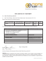
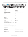
XL42
OPERATORS MANUAL
Telex Communications (UK) Ltd.
Klark Teknik Building
Walter Nash Road
Kidderminster
Worcestershire
DY11 7HJ
England
Tel: +44 1562 741515
Fax: +44 1562 745371
Website: www.midasconsoles.com
XL42 Dual Channel Strip Operators Manual
DOC02-XL42 Issue B - December 2005
© Telex Communications (UK) Ltd.
In line with the company’s policy of continual improvement, specifications and
function may be subject to change without notice. E&OE.
IMPORTANT SAFETY INSTRUCTIONS
CAUTION
RISK OF ELECTRIC SHOCK
DO NOT OPEN
WARNING: TO REDUCE THE RISK OF FIRE OR ELECTRIC SHOCK,
DO NOT EXPOSE THIS APPLIANCE TO RAIN OR MOISTURE
AVIS: RISQUE DE CHOC ELECTRIQUE. NE PAS OUVRIR
These symbols are internationally accepted symbols that warn of potential hazards
with electrical products.
The lightning flash with arrowhead symbol, within an equilateral triangle is
intended to alert the user to the presence of uninsulated “dangerous
voltage” within the product's enclosure that may be of sufficient magnitude
to constitute a risk of electric shock to persons.
The exclamation point within an equilateral triangle is intended to alert the
user to the presence of important operating and maintenance (servicing)
instructions in the literature accompanying the appliance.
1. Read these instructions.
2. Keep these instructions.
3. Heed all warnings.
4. Follow all instructions.
5. Do not use this apparatus near water.
6. Clean only with a dry cloth.
7. Do not block any of the ventilation openings. Install in accordance with the manufacturers
instructions.
8. Do not install near any heat sources such as radiators, heat registers, stoves, or other apparatus
(including amplifiers) that produce heat.
9. Do not defeat the safety purpose of the polarized or grounding-type plug. A polarized plug has two
blades with one wider than the other. A grounding type plug has two blades and a third grounding
prong. The wide blade or the third prong are provided for your safety. If the provided plug does not fit
into your outlet, consult an electrician for replacement of the obsolete outlet.
10. Protect the power cord from being walked on or pinched particularly at plugs, convenience
receptacles, and the point where they exit from the apparatus.
11. Only use attachments / accessories specified by the manufacturer.
12. Unplug this apparatus during lightning storms or when unused for long periods of time.
13. Refer all servicing to qualified personnel. Servicing is required when the apparatus is damaged in any
way, such as power-supply cord or plug is damaged, liquid has been spilled or objects have fallen into
the apparatus, the apparatus has been exposed to rain or moisture, does not operate normally, or has
been dropped.
Klark Teknik Group (UK) Plc, Klark Teknik Building, Walter Nash Road,
Kidderminster. Worcs. DY11 7HJ. England
Tel:+44 1562 741515 Fax:+44 1562 745371
www.midasconsoles.com www.klarkteknik.com
DECLARATION OF CONFORMITY
We, Klark Teknik Group (UK) PLC
of,
Klark Teknik Building, Walter Nash Road, Kidderminster, Worcestershire, DY11 7HJ
Declare that a sample of the following product:Product Type Number
XL42
Product Description
Dual Channel Strip
Nominal Voltage (s)
230V/115V
Current
70mA /
140mA
Freq
50/60Hz
to which this declaration refers, is in conformity with the following directives and/or standards:-
Directive(s)
Test Standard(s)
89/336/EEC Electromagnetic Compatibility Directive
amended by 92/31/EEC & 93/68/EEC
73/23/EEC Low Voltage Directive
amended by 93/68/EEC
Generic Emissions Standard
Generic Immunity Standard
Electrical Safety
Signed:............................
EN55013:1990
EN50082:1992
UL6500-03(Pending at time of publication)
E60065-03(Pending at time of publication)
EN60065:2002(Pending at time of publication)
Date: 7th May 2004
Name: Simon Harrison
Authority: Research & Development Director, Klark Teknik Group (UK) PLC
Attention!
Where applicable, the attention of the specifier, purchaser, installer or user is drawn to special limitations of
use which must be observed when these products are taken into service to maintain compliance with the
above directives. Details of these special measures and limitations to use are available on request and are
available in product manuals.
A Subsidiary of Telex communications, Inc.
Contents
Contents
Thank you for using a Midas XL42 dual channel creative equaliser. The XL42 has been developed to meet the
needs of demanding live sound engineers and meets the quality of build and performance that you would expect
from a Midas product.
The XL42 is backed up by the standard Midas Three Year Warranty.
Please take the time to complete and return the registration card. In view of this flexibility, we hope that you will
spend a little time reading through this operators' manual, as this will allow you to obtain the best results from
your XL42 with a minimum of effort.
Finally, enjoy your new Midas XL42!
Contents
Introduction
1
Before You Start
Installation Precautions
Voltage Selection and Power Connection
Safety Warning
Attention! Cables
Electric Fields
2
2
2
2
2
2
After You Have Unpacked the Unit
3
Front Panel
Input section
EQ section
Output section
5
6
7
8
Rear Panel
9
System Connection
13
Auto-mute Operation
14
Daisy Chain Operation
15
Technical Specification
17
XL42 Operators Manual - Page i
Contents
Contents
XL42 Operators Manual - Page ii
Introduction
The Midas XL42 is a 1U rack mounting, dual channel creative equaliser incorporating the XL4 four-band
parametric equalisation and XL4 mic/line pre-amplifiers with +48V phantom power.
Each channel has input gain, output level and pan rotary controls, 10-segment LED metering plus a switchable
insert send and return point. The XL42 also features Automute scene control from the Automute masters of XL
consoles, which are enabled by DIP switches on the rear of the unit.
The purpose of this unit is threefold:
1. To improve the audio quality of an inferior console by adding a Midas mic pre-amp and EQ.
2. To create custom mixing consoles through the ability to daisy chain multiple units. When linked together, the
combined outputs will sum, producing discrete L&R channels.
3. If a production requires, for example, 10 channels more than the input capacity of the master console, five
XL42s can be fitted in a standard rack together with any required dynamic processing, which can be inserted
via the XL42's insert points; thus creating a custom 10 into 2 mixer via the output daisy chain feature. The
resulting L and R outputs may then be routed to the master console via any convenient point, such as, a pair
of aux returns, group inputs, matrix inputs etc.
As a stand-alone unit, the XL42 is ideally suited to applications requiring a high quality front end, such as stereo
recording etc.
XL42 Operators Manual - Page 1
Before You Start
Installation Precautions
Do not install this unit in a location subjected to excessive heat, dust or mechanical vibration. Allow for adequate
ventilation around the unit, making sure the unit's vents are not obstructed. To avoid excessive heating of the
unit, avoid mounting the unit directly above power amplifiers or other devices that radiate significant amounts of
heat. Where necessary, use fan-cooled racks.
Voltage Selection and Power Connection
Mains power to the XL42 is supplied by means of a standard fused IEC power socket. The XL42 is designed to
operate at nominal mains voltages of 115V and 230V AC at either 50 or 60 Hz, however, upon first use (and
whenever the mains supply is changed) the input voltage selector on the rear of the unit must be set to reflect the
local power supply. This information is also printed on the rear of the unit, below the mains inlet socket.
This device must be earthed and must use an approved mains fuse. Before connecting to the mains supply,
ensure the fuse fitted is the correct type and rating as indicated on the rear panel (adjacent to fuse holder) and
that the correct mains supply voltage is selected.
Safety Warning
To completely disconnect this equipment from the AC mains, set the power switch to the off position. The power
switch shall remain readily operable.
Do not expose this equipment to dripping or splashing and ensure that no objects filled with liquids, such as
vases, are placed on the equipment.
For safety reasons the earth lead for this unit should never be disconnected. In the event of ground loop
problems, under no circumstances must the mains earth be removed. Instead, disconnect the signal screen at
one end of the connecting cables. Please note that this can only be done when the unit is being used within a
balanced system.
To prevent shock or fire hazard, do not expose the unit to rain or moisture. To avoid electrical shock do not
remove covers. Refer servicing to qualified personnel only.
Attention! Cables
The inputs and outputs are balanced on conventionally wired XLRs (pin 1 screen, pin 2 hot and pin 3 cold). This
product should only be used with high quality, screened twisted pair audio cables, terminated with metal-bodied
3-pin XLR connectors. Any other cable type or configuration for the audio signals may result in degraded
performance due to electromagnetic interference.
Note: The +48V phantom power can only be used with balanced cables.
Electric Fields
Should this product be used in an electromagnetic field that is amplitude modulated by an audio frequency signal
(20Hz to 20kHz), the signal to noise ratio may be degraded. Degradation of up to 60dB at a frequency
corresponding to the modulation signal may be experienced under extreme conditions (3V/m, 90% modulation).
No permanent damage or degradation of performance will be caused by these conditions.
XL42 Operators Manual - Page 2
After You Have Unpacked the Unit
Before unpacking the XL42, check packaging for signs of damage, as this could be an indication of damage to the
unit inside.
After unpacking the XL42, check the unit for signs of damage to the casing. Damage to consignments must
usually be reported to the courier within 24 hours in order for a claim to be made.
Please retain the packaging for your XL42, as it will prove useful if you need to transport the unit.
Please also retain the XL42's Operators Manual (this document) and any other associated documentation.
XL42 Operators Manual - Page 3
After You Have Unpacked the Unit
XL42 Operators Manual - Page 4
Front Panel
The XL42 is a highly featured 1U 19” rackmount, dual channel strip. The unit is split
into two identical channel strips, each with identical functionality but having
independent inputs and outputs.
Power On/Off switch: Conventional latching type switch,
which is on when in its fully in position and off when fully out.
The action of the switch is firm but does not require excessive
force, which may damage the unit. A red LED, to the left of
the power switch, illuminates to indicate that the XL42 is
receiving mains power.
Output section
EQ section
Input section
XL42 Operators Manual - Page 5
Front Panel
Input section
mic/line gain control knob: Gives a continuously
variable input gain control depending upon the input
selected, where:
Mic: +15dB to +70dB gain
Mic (PAD enabled): -10dB to +45dB
Ø switch: Phase switch inverts the input
signal by applying a 180° phase shift.
+48 switch: Phantom power +48V switch
allows connection of devices that require
phantom power, such as, condenser
microphones, direct inject (DI) boxes etc.
PAD switch: The line/pad switch provides 25dB of
attenuation to the input signal and allows the
connection of high output microphones or line level
signals. If using the XL42's optional transformercoupled input, the pad greatly reduces the risk of
saturation at very low frequencies.
XL42 Operators Manual - Page 6
Front Panel
EQ section
The bass, lo-mid, hi-mid and treble bands use dual concentric rotary controls. The outside ring controls the band
cut and boost in the range -15dB to +15dB. The inner ring of the dial controls the bandwidth of the filter in the
range 0.1 to 2 octaves (with a centre detent at 0.5 octave).
bass dual concentric rotary
control knob: Bass band
gain/attenuation adjustment is via
inner control knob. Bass bandwidth
is adjusted using the outer control
ring, enabled via bell switch
(immediately below).
freq (lo-cut) control knob:
Lo-cut filter control selects
the HPF frequency and is
continuously variable from
20Hz to 400Hz. Enabled by
the lo-cut switch.
lo-mid dual concentric rotary
control knob: Lo-mid band
gain/attenuation adjustment is via
inner control knob. Lo-mid bandwidth
is adjusted using outer control ring.
freq (lo-mid) control
knob: Lo-mid control
selects frequency at which
the lo-mid equaliser band
acts and is continuously
variable from 100Hz to
2KHz.
lo-cut switch:
Conventional latching
switch that enables lo-cut
filter when switch is on,
that is, in its fully in
position.
freq (bass) control:
Selects frequency at which
the bass equaliser band
acts; continuously variable
from 20Hz to 400Hz.
treble dual concentric rotary
control knob: Treble band
gain/attenuation adjustment is
via inner control knob. Treble
bandwidth is adjusted using
outer control ring, activated by
bell switch (immediately
below).
hi-mid dual concentric
rotary control knob: Hi-mid
band gain/attenuation
adjustment is via inner control
knob. Hi-mid bandwidth is
adjusted using outer control
ring.
eq switch:
Enables/disables equaliser
in the signal path.
freq (treble) control:
Selects frequency at which
the treble equaliser band
acts; continuously variable
from 1KHz to 20KHz.
freq (hi-mid) control:
Selects frequency at which
the hi-mid equaliser band
acts; continuously variable
from 400Hz to 8kHz.
bell (bass) switch: Conventional latching
switch enables/disables parametric EQ for
the bass band. When switch is in fully in
position, equaliser band will work in full
parametric mode. Otherwise, equaliser band
acts like a traditional MIDAS shelving
response EQ.
XL42 Operators Manual - Page 7
bell (treble) switch: Conventional
latching switch enables/disables parametric
EQ for the treble band. When switch is in
fully in position, equaliser band will work in
full parametric mode. Otherwise equaliser
band acts like a traditional MIDAS shelving
response EQ.
Front Panel
Output section
level/pan dual concentric rotary control knob: Adjusts pan or output level.
Pan control places the input within a stereo (left/right) mix and has a constant power law
such that, at its centre position, each output is attenuated by 3dB. Pan control is enabled by
the PAN switch (immediately below) and is adjusted using the outer control ring. With PAN
switch off, the XL42 is essentially two independent channel strips. With PAN switch on, the
output signal from each input strip is distributed between the two outputs.
The output level, adjust by the inner control knob, controls the output level in the range -¥
(infinity) to +10dB.
Output peak level meter: Monitors
the level of the channel. By default,
this is post-output level and pan,
although it may be internally set to be
pre-level pan and insert.
INS switch: Selects whether the insert
circuitry is patched into the audio signal
path. When the switch enabled (on, fully in
position) then the insert jacks are patched
into the audio signal path.
MUTE switch: Mutes the channel outputs. Mute may
also be controlled via the Automute link selected via the
"REMOTE CONTROL AUTOMUTE ASSIGNS" DIP switches
on the rear panel
Note: the insert point can be configured
internally using jumpers to be pre- or
post- EQ. The factory default setting is
Pre-EQ.
PAN switch: Enables the pan control on the
level/pan dual concentric rotary control knob.
XL42 Operators Manual - Page 8
LEFT INPUT
LEFT LINK INPUT
RIGHT INPUT
RIGHT LINK INPUT
RETURN SEND RETURN SEND
The XL42 rear panel houses both the input and output sockets as well as the insert
points, remote control and Automute sockets, and power inlet and selector.
Left and right inputs
Left and right link inputs
Left and right outputs
Left and right insertion points
LEFT
TO REDUCE THE RISK OF FIRE, REPLACE FUSE WITH THE SAME TYPE AND RATING
REMPLACER PAR
WARNING
UN FUSIBLE DE
DO NOT EXPOSE
MEME TYPE
THIS
APPLIANCE TO
CAUTION
ATTENTION RISQUE
RAIN OR MOiSTURE
THIS
DE CHOC NE
EQUIPMENT
SUPPLY
PAS ENLEVER
MUST BE
VOLTAGE
FUSE 5X20mm
EARTHED
115V T315mAL250V
115 / 230V~ 50-60Hz 40W
230V T160mAL250V
AUTOMUTE LINK
RIGHT
INSERTION POINTS
RIGHT
LEFT
REMOTE CONTROL
AUTOMUTE ASSIGNS
AUTOMUTE INPUT
NRTL/C
1995
RIGHT OUTPUT
PUSH
PUSH
LEFT OUTPUT
PUSH
PUSH
Rear Panel
Left and right remote
control Automute assigns
Automute input and link
230
Supply voltage selector switch
IEC Power Inlet. Your XL42 should come complete with the correct
IEC mains lead for the country in which it was intended for sale. If
replacing the mains lead, replace with a recommended part and
ensure that the fuse is of the correct type.
The XL42 must be earthed.
XL42 Operators Manual - Page 9
Rear Panel
Left and right link inputs: When used in a daisy chain, the link input is summed with the output from
the XL42's input channels to the output so that the daisy chain may continue. A much larger console can
be created by adding extra XL42s using the output from the last XL42 in the chain as the master output.
Input impedances:
Maximum input level:
20kOhm Balanced
+21dBu
The Left and Right link inputs may be configured using internal jumpers to sum with the channel input Preor Post- Output Level, Pan and Mute. The factory default setting is post Output Level, Pan and Mute.
Left and right inputs: Balanced XLR input to the channel strip
from microphones, DI boxes, line etc.
RIGHT OUTPUT
PUSH
PUSH
RIGHT LINK INPUT
RIGHT INPUT
Input impedances:
Mic:
Mic (with PAD):
2kOhm Balanced
3kOhm Balanced
Maximum input level:
Mic:
Mic (with PAD):
+6dBu
+31dBu
PUSH
PUSH
LEFT LINK INPUT
LEFT INPUT
LEFT OUTPUT
Left / Right Output: Balanced XLR output from the channel strip.
The output signal will be a combination of the link input plus the output from the XL42's input
channels. If pan is selected on either of the inputs, the outputs will be a stereo combination of the
input channels plus the link input. If pan is disabled on the channels, the output will be a
combination of the input channel and the link input only.
Please note that if one input channel has pan enabled and one does not, the channel with pan
enabled obeys the pan law of the pan pot. However, no signal is introduced into the other output.
Only when both channel pan switches are enabled does the unit enter full stereo mode, that is,
either output can be a combination of either input.
Maximum output level:
+21dBu
The Left and Right Outputs may be internally configured using jumpers to be pin 2 or pin 3 hot.
Factory default setting is pin 2 hot.
XL42 Operators Manual - Page 10
Rear Panel
Supply voltage selector switch: The supply voltage is switchable between 115VAC and
230VAC, and should be set to the mains power supply available in the country in which the unit is
to be used.
Caution!
The supply voltage selector switch must be set BEFORE plugging the unit into the mains.
UNDER NO CIRCUMSTANCES should the switch be changed whilst the unit is plugged in.
Remote Control Automute Assigns: The 9-pin plug for the
Automute system allows up to 8 Automute channels. The input
channels of the XL42 can be set to mute on one of these 8 Automute
channels by switching on the corresponding channel number on the
DIP switch for the XL42's input channels.
AUTOMUTE INPUT
230
WARNING
DO NOT EXPOSE
THIS APPLIANCE TO
RAIN OR MOiSTURE
NRTL/C
1995
REMOTE CONTROL
AUTOMUTE ASSIGNS
SUPPLY
VOLTAGE
115 / 230V~ 50-60Hz 40W
RIGHT
AUTOMUTE LINK
LEFT
INSERTION POINTS
RIGHT
LEFT
RETURN SEND RETURN SEND
Automute link/Automute input: Automute link socket can be used
to extend the Automute connection to other XL42s in the daisy chain.
Automute input should be wired according to diagram below.
12345
6789
54321
9876
Pin
Pin
Pin
Pin
Pin
Pin
Pin
Pin
Pin
1
2
3
4
5
6
7
8
9
Automute
Automute
Automute
Automute
Automute
Automute
Automute
Automute
Common
1
2
3
4
5
6
7
8
Left and right insertion points: Insert points can be used to add
additional processing into the signal path, for example, Dynamics
Processors, Graphic EQ, Effects, etc.
Input impedance:
Maximum input level:
20kOhm Balanced
+21dBu
The insert send and return are on independent balanced Bantam Jacks.
The insert point can be configured internally using jumpers to be pre- or
post- EQ. The factory default setting is Pre-EQ.
XL42 Operators Manual - Page 11
Rear Panel
XL42 Operators Manual - Page 12
System Connection
The XL42 is a versatile expansion to any system, or a complete system on its own.
You can use it:
As a replacement for an inferior mic pre-amp.
!
Plug the microphone or DI box into the XL42 and the output into the line input of your console. You can also
use the XL42 EQ and bypass your console's EQ. Set PAN to off for mono operation or on for stereo operation.
As a better EQ section for your console.
!
Plug the XL42 into the insert point of your console (Desk Send to XL42 Input and XL42 Output to Desk Return).
Set the PAD switch on the XL42 to the in position in for a line level signal.
As an expansion to your console.
!
Connect your XL42s in a daisy chain configuration. Connect outputs from the last XL42 into a stereo channel
(or two mono channels) on your console or into a stereo/effects return.
As a high quality pre-amp and EQ.
!
Plug your microphones, such as a stereo condenser pair for recording, into the XL42 and the outputs into a
DAT, CD or hard disk recorder.
The XL42 is the perfect companion for any system and could even be used for computer audio or drum sub-mixing
where a high quality pre-amp and EQ is required.
XL42 Operators Manual - Page 13
Auto-Mute Operation
The XL42 can be used within an Automute system. The standard 9-pin plug can control up to eight independent
mono channels, each of which can be addressed by the XL42.
To assign an Automute address for each channel, the REMOTE CONTROL AUTOMUTE ASSIGNS should be turned
on for the desired Automute address, that is, LEFT ASSIGN 2 would make the left-hand channel of the XL42 mute
on channel 2 of the Automute system.
AUTOMUTE INPUT
NRTL/C
REMOTE CONTROL
AUTOMUTE ASSIGNS
AUTOMUTE LINK
RIGHT
LEFT
Each channel may be assigned to more than one Automute channel by switching each of the required DIP
switches.
The Automute plugs are wired as follows:
12345
6789
54321
Pin
Pin
Pin
Pin
Pin
Pin
Pin
Pin
Pin
1
2
3
4
5
6
7
8
9
Automute
Automute
Automute
Automute
Automute
Automute
Automute
Automute
Common
1
2
3
4
5
6
7
8
9876
The XL42 Automute system is compatible with all MIDAS XL series consoles, hence the XL42 is an ideal expansion
to an XL series console when extra channels are required.
XL42 Operators Manual - Page 14
Daisy-Chain Operation
A number of XL42s can be connected in a daisy chain configuration to form a larger console or to expand an
existing console. (32 channels of XL quality EQ and mic pre-'s will fit into a 16U.)
Inputs
1 and 2
Automute input
230
TO REDUCE THE RISK OF FIRE, REPLACE FUSE WITH THE SAME TYPE AND RATING
AUTOMUTE INPUT
REMPLACER PAR
WARNING
UN FUSIBLE DE
DO NOT EXPOSE
MEME TYPE
THIS APPLIANCE TO
CAUTION
ATTENTION RISQUE
RAIN OR MOiSTURE
THIS
DE CHOC NE
SUPPLY
EQUIPMENT
PAS ENLEVER
MUST BE
VOLTAGE
FUSE 5X20mm
EARTHED
115 / 230V~ 50-60Hz 40W
115V T315mAL250V
AUTOMUTE LINK
230V T160mAL250V
230
TO REDUCE THE RISK OF FIRE, REPLACE FUSE WITH THE SAME TYPE AND RATING
AUTOMUTE INPUT
REMPLACER PAR
WARNING
UN FUSIBLE DE
DO NOT EXPOSE
MEME TYPE
THIS APPLIANCE TO
CAUTION
RAIN OR MOiSTURE
ATTENTION RISQUE
THIS
DE CHOC NE
SUPPLY
EQUIPMENT
PAS ENLEVER
MUST BE
VOLTAGE
FUSE 5X20mm
EARTHED
115 / 230V~ 50-60Hz 40W
115V T315mAL250V
AUTOMUTE LINK
230V T160mAL250V
NRTL/C
REMOTE CONTROL
AUTOMUTE ASSIGNS
RIGHT
LEFT
NRTL/C
REMOTE CONTROL
AUTOMUTE ASSIGNS
RIGHT
LEFT
NRTL/C
REMOTE CONTROL
AUTOMUTE ASSIGNS
RIGHT
LEFT
NRTL/C
REMOTE CONTROL
AUTOMUTE ASSIGNS
RIGHT
LEFT
PUSH
PUSH
RIGHT LINK INPUT
RIGHT INPUT
PUSH
PUSH
RIGHT LINK INPUT
RIGHT INPUT
PUSH
PUSH
RIGHT LINK INPUT
RIGHT INPUT
PUSH
PUSH
RIGHT LINK INPUT
RIGHT INPUT
PUSH
PUSH
LEFT LINK INPUT
LEFT INPUT
PUSH
PUSH
LEFT LINK INPUT
LEFT INPUT
PUSH
PUSH
LEFT LINK INPUT
LEFT INPUT
PUSH
PUSH
LEFT LINK INPUT
LEFT INPUT
Inputs
3 and 4
1995
INSERTION POINTS
RIGHT
LEFT
RETURN SEND RETURN SEND
RIGHT OUTPUT
LEFT OUTPUT
Inputs
5 and 6
1995
INSERTION POINTS
RIGHT
LEFT
RETURN SEND RETURN SEND
RIGHT OUTPUT
LEFT OUTPUT
Inputs
7 and 8
1995
INSERTION POINTS
RIGHT
LEFT
RETURN SEND RETURN SEND
RIGHT OUTPUT
LEFT OUTPUT
1995
INSERTION POINTS
RIGHT
LEFT
RETURN SEND RETURN SEND
RIGHT OUTPUT
LEFT OUTPUT
“Master” outputs - to
mixer, amplifer or
recording device
As shown in the diagram above, each channel has its own input plus the output from the previous XL42 so that at
the last point of the chain, the output is a combination of each input.
Depending on the use of each channel PAN, this may be a stereo image or all the left-hand channels grouped and
all the right-hand channels grouped.
Optionally, you may wish to use the Automute feature. Here the output from the master console (any MIDAS XL
series) is inserted at the top of the chain and linked into each unit.
XL42 Operators Manual - Page 15
Daisy-Chain Operation
XL42 Operators Manual - Page 16
Technical Specification
0
60
160
6
400
-15
0
6
0
6
6
0
6
6
1
0.1
2
+/-
+15
+70
mic/line gain
PAD +48 /O
line/pad phase
20
freq
60
+15 -15
160 bass300
+15 -15
lo-cut 20 freq 400 bell 100 freq 2k eq
400
+15 -15
3k hi-mid 3k
1k lo-mid 1k
freq
8k
1k
8k
freq
treble
20k
+15
bell
TO REDUCE THE RISK OF FIRE, REPLACE FUSE WITH THE SAME TYPE AND RATING
AUTOMUTE INPUT
REMPLACER PAR
WARNING
UN FUSIBLE DE
DO NOT EXPOSE
MEME TYPE
THIS APPLIANCE TO
CAUTION
RAIN OR MOiSTURE
ATTENTION RISQUE
THIS
DE CHOC NE
SUPPLY
EQUIPMENT
PAS ENLEVER
MUST BE
VOLTAGE
FUSE 5X20mm
EARTHED
115 / 230V~ 50-60Hz 40W
115V T315mAL250V
AUTOMUTE LINK
230V T160mAL250V
230
0.3
+15
+12
+9
+6
+3
0
+10
-3
level/pan -6
-9
INS PAN MUTE -12
0
6
6
level
pan
+25
+15
+35
+70
RIGHT
LEFT
20
mic/line gain
PAD +48 /O
line/pad phase
NRTL/C
REMOTE CONTROL
AUTOMUTE ASSIGNS
0
60
freq
160
6
400
-15
60
0
6
+15 -15
160 bass300
0
6
6
+15 -15
2k
eq
400
freq
8k
+15 -15
1k
6
6
3k hi-mid 3k
1k lo-mid 1k
lo-cut 20 freq 400 bell 100 freq
0
6
6
8k
freq
treble
20k
PUSH
PUSH
RIGHT LINK INPUT
RIGHT INPUT
bell
+15
+15
+12
+9
+6
+3
0
+10
-3
level/pan -6
-9
INS PAN MUTE -12
0
0
0
+35
0
0
+25
width
level
XL42
ON
pan
PUSH
PUSH
LEFT LINK INPUT
LEFT INPUT
1995
INSERTION POINTS
RIGHT
LEFT
RETURN SEND RETURN SEND
RIGHT OUTPUT
LEFT OUTPUT
Input Impedance
Mic
Mic + Pad
Link & Insert
2kOhm Balanced
3kOhm Balanced
20kOhm Balanced
Input Gain (all controls at 0dB)
Mic
Mic + Pad
Link & Insert
Continuously variable from +15dB to +70dB
Continuously variable from -10dB to +45dB
0dB
Maximum Input Level
Mic
Mic + Pad
Link & Insert
+6dBu
+31dBu
+21dBu
CMR at 1kHz
Mic (gain + 60dB)
Mic + Pad (gain +35dB)
Link & Insert
>70dB
>50dB
>60dB
Frequency Response (20Hz to 20kHz)
Any input
+0dB to -1dB
Noise (20Hz to 20kHz)
Mic EIN ref. 150 Ohm (gain + 60dB)
Transformer Mic Input EIN ref. 150 Ohm (gain + 60dB)
System Noise at 0dB (one channel only)
-129dBu
-127dBu
-88dBu
System Noise (20 to 20kHz)
Summing Noise (12 channels routed with faders down)
Line to Mix Noise (12 channels routed at 0dB, pan centre)
Summing Noise (48 channels routed with faders down)
Line to Mix Noise (48 channels routed at 0dB, pan centre)
-83dB
-81dB
-81dB
-75dB
Distortion at 1kHz
Mic (+ 40dB gain, 0dBu output)
Link (0dBu)
<0.03%
<0.03%
Output Impedance
All Outputs
50 Ohm Balanced Source to drive >600 Ohm
Maximum Output Level
All Outputs
50 Ohm Balanced Source to drive >600 Ohm
into >600 Ohm +21dBu
XL42 Operators Manual - Page 17
Technical Specification
Metering
Type
10 Segment LED Bargraph - Peak Reading
Equaliser
Hi pass slope
Hi pass frequency
12dB/Oct
Continuously variable -3dB point from 10Hz to 400Hz
Treble Gain
Treble Shelving Freq.
Treble Bell Freq.
Treble Bell Bandwidth
Hi Mid Gain
Hi Mid Freq.
Hi Mid Bandwidth
Lo Mid Gain
Lo Mid Freq.
Lo Mid Bandwidth
Bass Gain
Bass Shelving Freq.
Bass Bell Freq.
Bass Bell Bandwidth
Continuously variable +15dB to -15dB
Centre detent = 0dB
Continuously variable - 3dB point from 1kHz to 20kHz
Continuously variable centre from 1kHz to 20kHz
Continuously variable 0.1 Oct. to 2 Oct
Centre detent = 0.5 Oct
Continuously variable +15dB to -15dB
Centre detent = 0dB
Continuously variable centre from 400Hz to 8kHz
Continuously variable 0.1 Oct. to 2 Oct.
Centre detent = 0.5 Oct
Continuously variable +15dB to -15dB
Centre detent = 0dB
Continuously variable centre from 100Hz to 2kHz
Continuously variable 0.1 Oct. to 2 Oct
Centre detent = 0.5 Oct
Continuously variable +15dB to -15dB
Centre detent = 0dB
Continuously variable - 3dB point from 20Hz to 400Hz
Continuously variable centre from 20Hz to 400Hz
Continuously variable 0.1 Oct. to 2 Oct
Centre detent = 0.5 Oct
Automute System
Channel Quantity
Mute ON Voltage
Mute Off Voltage
Mute Line Load
8
+3 to +20V
-20 to +2V
>500kOhm
Power
Nominal Mains Voltage
Mains Consumption
Phantom Voltage Supply
Maximum Phantom Current
115V/230V
40W
+48V ± 5%
<10mA
Dimensions
Width
Depth
Height
482mm (19 inches)
250mm (10 inches)
44mm (1.75 inches)
Weight
Nett
Shipping
3kg
4kg
Options
Mic Transformer
Factory-Fit Only
Output Transformer
Factory-Fit or Retro-fit
XL42 Operators Manual - Page 18
Notes
XL42 Operators Manual - Page 19