1
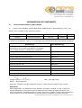
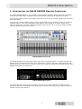
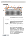
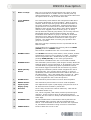
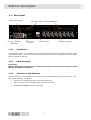
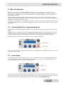
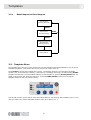
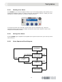
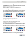
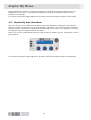
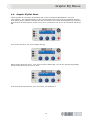
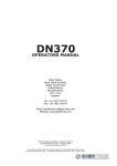
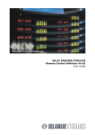
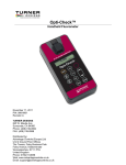
HELIX RAPIDE DN9331
Graphic Controller
Operator Manual
Klark Teknik
Klark Teknik Building
Walter Nash Road
Kidderminster
Worcestershire
DY11 7HJ
England
Tel: +44 1562 741515
Fax: +44 1562 745371
Email: [email protected]
Website: www.klarkteknik.com6
HELIX RAPIDE DN9331 Graphic Controller Operator Manual
DOC02-DN9331 Issue B - August 2006
© Telex Communications (UK) Limited.
In line with the company’s policy of continual improvement, specifications and function may be
subject to change without notice. This Operators Manual was correct at the time of writing. E&OE.
IMPORTANT SAFETY INSTRUCTIONS
The lightning flash with arrowhead symbol within an equilateral triangle, is
intended to alert the user to the presence of uninsulated “Dangerous Voltage”
within the product's enclosure that may be of sufficient magnitude to constitute a
risk of electric shock to persons.
The exclamation point within an equilateral triangle, is intended to alert the user
to the presence of important operating and maintenance (servicing) instructions
in the literature accompanying the product.
1.
Read these instructions.
2.
Keep these instructions.
3.
Heed all warnings.
4.
Follow all instructions.
5.
Do not use this apparatus near water.
6.
Clean only with a dry cloth.
7.
Do not block any of the ventilation openings. Install in accordance with the manufacturer’s
instructions.
8.
Do not install near any heat sources such as radiators, heat registers, stoves, or other
apparatus (including amplifiers) that produce heat.
9.
Do not defeat the safety purpose of the polarized or grounding-type plug. A polarized plug has
two blades with one wider than the other. A grounding type plug has two blades and a third
grounding prong. The wide blade or the third prong are provided for your safety. If the
provided plug does not fit into your outlet, consult an electrician for replacement of the
obsolete outlet.
10.
Protect the power cord from being walked on or pinched particularly at plugs, convenience
receptacles and the point where they exit from the apparatus.
11.
Only use attachments/accessories specified by the manufacturer.
12.
Unplug this apparatus during lightning storms or when unused for long periods of time.
13.
Refer all servicing to qualified personnel. Servicing is required when the apparatus has been
damaged in any way, such as power supply cord or plug is damaged, liquid has been spilled or
objects have fallen into the apparatus, the apparatus has been exposed to rain or moisture,
does not operate normally, or has been dropped.
14.
Use the mains plug to disconnect the apparatus from the mains.
15.
“WARNING – TO REDUCE THE RISK OF FIRE OR ELECTRIC SHOCK, DO NOT EXPOSE THIS
APPARATUS TO RAIN OR MOISTURE”
16.
“DO NOT EXPOSE THIS EQUIPMENT TO DRIPPING OR SPLASHING AND ENSURE THAT NO
OBJECTS FILLED WITH LIQUIDS, SUCH AS VASES, ARE PLACED ON THE EQUIPMENT”
17.
“THE MAINS PLUG OF THE POWER SUPPLY CORD SHALL REMAIN READILY OPERABLE”
Telex Communications (UK) Limited, Klark Teknik Building,
Walter Nash Road, Kidderminster. Worcs. DY11 7HJ. England.
Tel: +44 1562 741515 Fax: +44 1562 745371
www.midasconsoles.com www.klarkteknik.com
DECLARATION OF CONFORMITY
We,
Telex Communications (UK) Limited
of,
Klark Teknik Building, Walter Nash Road, Kidderminster, Worcestershire, DY11 7HJ.
Declare that a sample of the following product:
Product Type Number
HELIX RAPIDE
DN9331
Product Description
Graphic Equaliser
Remote Controller
Nominal Voltage(s)
115V AC
230V AC
Current
1000mA
500mA
Freq
50/60Hz
to which this declaration refers, is in conformity with the following directives and/or standards:
Directive(s)
Test Standard(s)
89/336/EEC Electromagnetic Compatibility Directive
amended by 92/31/EEC & 93/68/EEC 73/23/EEC,
Low Voltage Directive, amended by 93/68/EEC
Generic Standard Using EN55103 Limits and Methods
EN50081/1
Class B Conducted Emissions PAVI
EN55103
Class B Radiated Emissions PAVI
EN55103
Fast Transient Bursts at 2kV
EN61000-4-4
Static Discharge at 4kV
EN61000-4-2
Electrical Stress Test
EN60204
Electrical Safety
EN60065
Signed: ............................
Name: Simon Harrison
Date: 10th May 2006
Authority: Research and Development Director, Telex Communications (UK) Limited
Attention!
Where applicable, the attention of the specifier, purchaser, installer or user is drawn to
special limitations of use which must be observed when these products are taken into
service to maintain compliance with the above directives. Details of these special measures
and limitations to use are available on request and are available in product manuals.
Company registration No. 2414018. A Subsidiary of Telex Communications Inc.
Thank You For Using This Klark Teknik Product
Our engineers have designed this product with uncompromising dedication to providing the superb
audio performance, ease of use and rugged reliability that meets the demands of live sound
engineering.
Please take time to complete and return the Klark Teknik three-year warranty registration card and,
to obtain maximum performance with minimum effort, refer to this user manual. Please ensure that
you read both the Important Safety Instructions and Attention! pages.
Finally, enjoy your new HELIX RAPIDE DN9331!
CONTENTS
ATTENTION! ......................................................................................... 1
1.
INTRODUCING THE HELIX RAPIDE GRAPHIC CONTROLLER.....................................3
1.1.
Front Panel................................................................................................................ 4
1.2.
Rear Panel ................................................................................................................ 6
1.2.1
Ventilation .......................................................................................................... 6
1.2.2
Rack Mounting ..................................................................................................... 6
1.2.3
Connectors and Switches....................................................................................... 6
2.
GETTING STARTED .....................................................................................7
2.1.
Working With The Programming Panel ........................................................................... 7
2.2.
Home Page................................................................................................................ 7
2.3.
User Menus ............................................................................................................... 8
2.4.
Templates ................................................................................................................. 8
3.
RECALLING AND STORING TEMPLATES ..............................................................9
3.1.
Understanding Templates ............................................................................................ 9
3.2.
Template Recall ......................................................................................................... 9
3.2.1
3.3.
Recall Sequence Flow Diagram ............................................................................. 10
Template Store ........................................................................................................ 10
3.3.1
Naming Your Store ............................................................................................. 11
3.3.2
Saving Your Store .............................................................................................. 11
3.3.3
Store Sequence Flow Diagram.............................................................................. 11
4.
WORKING WITH GRAPHIC EQ MENUS ............................................................ 13
4.1.
Graphic EQ Channel Display....................................................................................... 13
4.2.
Graphic EQ Response Menu ....................................................................................... 13
4.3.
Graphic EQ Auto Gain Menu ....................................................................................... 14
4.4.
Graphic EQ Flat Menu ............................................................................................... 15
4.5.
Copy EQ Menu ......................................................................................................... 16
4.6.
Graphic EQ Menu Sequence Flow Diagram ................................................................... 18
5.
USING SET UP MENUS...............................................................................19
5.1.
Multi-master Mode Menu ........................................................................................... 19
5.2.
HELIX Get All Menu .................................................................................................. 20
5.3.
Solo-Tracking Console Type Menu ............................................................................... 22
5.4.
Channel Set Up Menu................................................................................................ 22
5.5.
STS Solo-Tracking Set-Up Menu ................................................................................. 23
5.5.1
Making Changes................................................................................................. 23
5.5.2
STS Solo-Tracking Options .................................................................................. 24
5.5.3
Solo-Tracking Set-Up Examples............................................................................ 24
5.6.
Channel Long Name Set-Up Menu ............................................................................... 25
5.7.
Channel Short Name Set-Up Menu .............................................................................. 25
5.8.
LCD Contrast Menu................................................................................................... 26
5.9.
LED Brightness Menu ................................................................................................ 26
5.10. Name Unit Menu ...................................................................................................... 27
5.11. Name Working Memory Menu..................................................................................... 27
5.12. Power-Up Logo Menu ................................................................................................ 28
5.13. Ethernet Communications Set-Up Menu ....................................................................... 28
5.14. Ethernet Subnet Mask Menu....................................................................................... 29
5.15. Menu Sequence Flow Diagram .................................................................................... 30
6.
TECHNICAL SPECIFICATION .........................................................................31
ATTENTION!
Please ensure that you read and follow the
IMPORTANT SAFETY INSTRUCTIONS at the front of this manual and the
SAFETY WARNINGS and INSTALLATION CONSIDERATIONS given below.
Safety Warning
To prevent shock or fire hazard, do not expose the unit to rain or moisture. To avoid electrical shock
do not remove covers. Refer servicing to qualified personnel only.
This unit is fitted with a standard fused IEC mains power socket. The unit contains a switch mode
power supply that automatically adjusts itself to 50/60Hz mains supplies in the 100V to 240V (±10%)
AC range. This information is printed on the rear of the unit, below the mains inlet socket.
Before connecting this unit to the mains supply, ensure that the fuse fitted is the correct type and
rating as indicated on the rear panel.
For safety reasons the mains earth lead should never be disconnected. In the event of ground loop
problems, disconnect the signal screen at one end of the connecting cables – note that this can only
be done when the unit is used within a balanced system.
Installation Considerations
Location:
Do not install this unit in a location subjected to excessive heat, dust or
mechanical vibration. Allow for adequate ventilation around the unit, making sure
the unit’s fans and vents are not obstructed. To prevent excessive heating of the
unit, avoid mounting the unit directly above power amplifiers or other devices
that radiate significant amounts of heat. Where necessary use fan cooled racks.
Rack mounting:
When installing this unit in a rack you must ensure that 1U of rack space is left
free above the unit for efficient ventilation.
Electric Fields:
Should this product be used in an electromagnetic field that is amplitude
modulated by an audio frequency signal (20Hz to 20kHz), the signal to noise ratio
may be degraded. Degradation of up to 60dB at a frequency corresponding to the
modulation signal may be experienced under extreme conditions (3V/m, 90%
modulation).
After Unpacking
Please retain the original packing for use should you need to transport or ship this unit.
Please inspect the unit carefully for any signs of damage that may have occurred in transit and notify
the courier immediately if you feel that any damage has occurred.
1
2
DN9331 Description
1. INTRODUCING THE HELIX RAPIDE GRAPHIC CONTROLLER
The HELIX RAPIDE DN9331 is a motorised, 31-band graphic equaliser, remote controller compatible
with both the Midas range of digital consoles and the Klark Teknik digital equalisation system.
This controller offers instant recall of fader positions by the use of 31 console-quality, high-resolution,
motorised faders.
A flexible user interface allows custom remote channel assignments across four banks of 32 channel
selection buttons. Four freely assignable group buttons and a global ‘all channels’ button allow
relative adjustment of channels, especially important when the priority is to stop on-stage feedback
first, and determine the source second.
HELIX RAPIDE Front View
The HELIX RAPIDE is the networking centre of the Show Command System. An eight-external port
Ethernet hub is incorporated into the device, allowing the connection of Helix digital equalisers and
system processors, with wired or wireless connections to laptop or tablet PCs running the ELGAR Helix
EQ RCS and System Controller RCS.
HELIX RAPIDE Rear View
The HELIX RAPIDE is ‘backwards-compatible’ with the original Helix DN9340 and DN9344 digital
equalisers that may be interfaced using Ethernet-to-serial converters, but only to units running host
software version 4.00 and later.
3
DN9331 Description
1.1. Front Panel
10
4
3
5
9
8
12
14
11
15
2
7
6
13
1
1
Motorised faders
Thirty-one servo-controlled, motorised 100 mm faders
represent the ISO-standard frequencies defined in BS EN ISO
226: 1997.
2
A, B, C and D bank
selection (BANKS)
buttons
Four momentary-action bank buttons (A, B, C and D), with
integral blue LEDs, are used to select which of the four available
banks of 32 channels is selectable using the channel access key
switches (see item 3). HELIX RAPIDE has a ‘sticky’ memory of
the last channel selected in each bank and, on entry to any
bank, the last selected channel will be automatically selected
and the corresponding button illuminated. Pressing the HOME
(SETUP) button to return to the Home Page cancels this
‘sticky’ memory function.
3
1 to 32 channel
access (CHANNELS)
buttons
Thirty-two momentary-action channel access buttons are used
to access the individual graphic EQ channels in a bank. The
channel access buttons have integral blue LEDs and are
arranged in two rows of sixteen. Successive presses of one of
the channel access buttons will navigate the user through the
Graphic EQ Menu options for the assigned channel.
The HELIX RAPIDE indicates linked channels (always only in
pairs), but does not allow channel linking/unlinking. All
changes to one channel of a linked pair are also applied to the
other channel within that pair. Linked channels within the same
bank are indicated by the simultaneous illumination of both
their channel access buttons when that bank is selected. If two
linked channels are in different banks, their channel access
buttons will illuminate when their respective banks are selected.
If one channel of a linked channel pair is added to a group the
other linked channel is automatically added to that group, so
that any changes to the group members similarly affect both
linked channels. In global mode, all assigned channels will be
illuminated, so that any linked pairs of channels will respond
identically to the relative adjustments made.
4
DN9331 Description
4
Write-on strips
Each row of 16 channel access buttons has a write-on strip
located underneath it to enable users to manually mark up
channel assignments. In addition, each of the bank buttons has
an adjacent write-on strip to the left-hand side.
5
1 to 4 GROUPS
buttons
Four momentary-action buttons with integral blue LEDs allow
for relative adjustment of group members. When a group is
selected, both its respective group button and the buttons of
the group members are illuminated. Pressing and holding a
group button for more than three seconds causes the HELIX
RAPIDE to enter Group Set-Up Mode, which allows individual
channels to be toggled in and out of the group. In Group
Set-Up Mode the selected group button, the currently selected
bank button and the selected channel button will remain
illuminated when added to a group or will flash if unselected.
Channels in more than one bank can all be part of the same
group and the bank buttons remain active while a group is
selected. This applies both in normal group operation and
group set-up mode.
Each time a group is selected, the user is presented with all
faders at 0dB.
Group mode may be cancelled by pressing either the HOME
(SETUP) button or GLOBAL button.
This function is disabled when unit is connected to ELGAR.
6
GLOBAL button
The GLOBAL momentary-action button, when pressed, enables
simultaneous control of every channel in a bank. This button
has an integral blue LED. Global Mode may be cancelled by
pressing HOME (SETUP) or one of the group buttons.
This function is disabled when unit is connected to ELGAR.
7
BYPASS button
This momentary-action button, with integral red LED, allows the
selected channel, group of channels, or all channels in the case
of Global Mode, to bypass the graphic equalisation function.
This function toggles on and off with successive key presses.
8
HOME (SETUP)
button
Pressing this momentary-action button navigates the user to
the Home Page. Any currently active channel, or group of
equalisation, will be deselected and all the faders will return to
the 0dB position. This is the default state on power up. When
in the Home Page, pressing and holding this button for one
second navigates the user to the Set-Up Menu.
9
STORE button
This momentary-action button is used to store templates.
10
RECALL button
This momentary-action button is used to recall templates.
11
Liquid crystal
display (LCD)
This alphanumeric liquid crystal display (LCD) has two lines of
20 characters and is backlit by a blue LED.
12
Encoders
Three rotary encoders are used for data entry. Each has an
illuminated annular ring.
13
Meters
Two, eleven–segment, LED meters provide input and output
metering. These are active when an individual channel is
selected, but are inactive in Group and Global Modes and in the
Home Page.
14
ETHERNET LED
An LED indicates data communication activity between the
HELIX RAPIDE main processor and the onboard Ethernet
Switch. It is illuminated at all times when the unit is powered
on, and flashes while data is being received or transmitted.
15
POWER button
Press to switch the unit on or off.
5
DN9331 Description
1.2. Rear Panel
Mains input socket
Fan unit – DO NOT
OBSTRUCT
1.2.1
Ventilation slots – DO NOT OBSTRUCT
Mains circuit
breaker
STS connector
Ethernet connectors
Ventilation
A guarded fan unit is used to achieve powered airflow within the unit and ventilation slots form part
of the airflow system. The fan unit and ventilation slots must remain unobstructed at all times that
power is applied to the unit.
1.2.2
Rack Mounting
Important!
When installing the unit in a rack, you must ensure that 1U of rack space is left free above
the unit for efficient ventilation.
1.2.3
Connectors and Switches
A rear panel mains circuit breaker rocker switch is sited alongside the mains input connector. The
unit has the following connectors:
•
A Bulgin PF11 snap-fit IEC mains inlet with integral fuse.
•
A 9-pin ‘D’-type, Solo Tracking System interface connector.
•
Eight Neutrik NE8FBH Ethercon connectors.
6
Getting Started
2. GETTING STARTED
Once you are ready to use HELIX RAPIDE and connect it to your system, it should come as no
surprise to find that your new unit’s settings conform to the factory defaults. A primary purpose of
this guide is to enable you to configure and customise your HELIX RAPIDE so that its performance
best meets your needs.
Images within this guide generally relate to a unit that conforms to those factory defaults and you
should be aware that customisation and configuration might mean that the images in this guide differ
slightly from those you see on the unit.
To begin the customisation and configuration process, you will first need to be familiar with the use of
the programming panel, so it is recommended that you check out this section before jumping directly
to Section 2.
2.1. Working With The Programming Panel
Parameters for the HELIX RAPIDE are monitored and controlled using the programming panel shown
below.
Graphic Equaliser Settings, and System Configuration Settings can both be accessed and controlled
using this panel. Each menu page uses a standard layout that relates the displayed parameters to
the three data entry encoder control knobs, which are used to adjust those parameter values.
Template store and recall is also controlled using the programming panel.
encoder control
annular ring
For any given menu page, active encoder controls are indicated by the illumination of the annular ring
surrounding the control.
2.2. Home Page
The Home Page is the default page on power-up. No channels or groups are selected and all faders
are in the 0dB (flat) position. The LCD shows the unit name on the top line with the name of the
current working memory displayed on the second line.
None of the encoders are active and their associated annular rings are not illuminated. Elsewhere on
the unit, all the channel and group select buttons are active to allow selections to be made. A return
to the Home Page can be made at any time by repeatedly pressing HOME (SET UP).
7
Getting Started
2.3. User Menus
There are two types of user menu: Graphic EQ and Set Up. The Graphic EQ menu is active when an
individual channel is selected or when a group of channels or all channels (via the Global key) are
selected. The Set Up menu becomes active when the HOME (SET UP) key is pressed for one
second. A full description of these menus is given in Sections 4 and 5 of this User Guide.
2.4. Templates
The HELIX RAPIDE can store up to 16 templates, which are stored, recalled and edited via the
programming panel. A full description of these processes is given in Section 3.
8
Templates
3. RECALLING AND STORING TEMPLATES
3.1. Understanding Templates
The HELIX RAPIDE can store up to 16 templates, which contain preset data that you can recall to
save you having to set up the HELIX RAPIDE each time. The templates are accessed via the
programming panel, where they can be stored, recalled and renamed.
Each of the 16 templates contains the following:
•
Template name (see Section 3.3.1).
•
STS console type (see Section 5.3).
•
STS type (see Section 5.5).
•
Banks A to D channel access button assignments (see Section 5.4). Please note that some fields
may be empty as they are dependent on EQ mode, STS console selections etc.
•
Group assignments 1 to 4 (see item 5 on page 5). Each of the four group assignments contains
a list of all channels in all banks in that group.
3.2. Template Recall
Pressing the RECALL button will initiate the template recall sequence, which can be done at any level
in the menu structure. A display will appear showing the last template to be recalled on the top line
and a message reminding you that pressing HOME (SETUP) will abort the recall, underneath.
Once RECALL has been pressed, you can use the left encoder can to step through the 16 templates
(T00 to T15) in turn.
Template T00 is blank and has all fader settings at zero and all channel access button mappings set
to “OFF”. This template, which is offered for selection the first time RECALL is pressed, acts as a
master and cannot overwritten.
When the required template is displayed, pressing RECALL again recalls its settings into the working
memory. However, if you press HOME (SETUP) instead of RECALL, the template recall sequence is
aborted and you will be returned to the top of the menu structure.
9
Templates
3.2.1
Recall Sequence Flow Diagram
Top Of Menu
(Nothing Selected)
RECALL
Select Menu
(To Be Recalled)
HOME
RECALL
Template’s Contents
Recalled Into
Working Memory
HELIX Get All
3.3. Template Store
The template store process is used to save the current settings of the HELIX RAPIDE in one of the 15
available templates. This can be done at any level in the menu structure.
Press STORE to access the template store menu. The display shows the current target template
number (T01 in the following example). Below this is a message informing you that pressing STORE
at again will store the current template settings to this template or pressing HOME (SETUP) will any
stage in this process will abort the sequence. Pressing HOME (SETUP) at any time during the
template sequence will exit without saving.
Use the left encoder (which will be active and illuminated) to step through the templates (T01 to T15)
until you reach your chosen template location, then go to Section 3.3.1.
10
Templates
3.3.1
Naming Your Store
Press STORE at your chosen template location to go to the naming display, which allows you to
rename the template in which you wish to store your new template settings. Initially, all of the
templates are named “DEFAULT” (as shown illustrated below).
To change the name of the template, which can be up to 20 characters long, select the
character/number/symbol with the middle encoder and use the left encoder to move to the
next/previous character position.
3.3.2
Saving Your Store
Pressing STORE again completes the template store sequence and returns you to the top of the
menu structure.
3.3.3
Store Sequence Flow Diagram
Top Of Menu
(Nothing Selected)
STORE
LEFT ENCODER
HOME
Select Target
Template
For Store
Top Of Store Menu
Current Template
Number Selected
HOME
STORE
Enter
Template Name
STORE
STORE
Working Template
Contents Stored
11
HOME
Templates
12
Graphic EQ Menus
4. WORKING WITH GRAPHIC EQ MENUS
The Graphic EQ menu set is active if either an individual channel, a group of channels, or all channels
(via the GLOBAL button) is selected. Further presses of the appropriate individual channel, group or
global access button will step you through the menu.
This section describes the options available within the menus. A Sequence Flow Diagram, which
shows the inter-relationship of the Graphic EQ menu pages, can be found at the end.
4.1. Graphic EQ Channel Display
This is the Graphic EQ top level menu and displays the name assigned to the channel (either the Helix
long name or the digital console eight-character name) on the top line. The lower line displays either
the STS solo tracking assignment (in the case of Helix EQs) or the digital EQ type. This is the display
that you will normally see during operation, while the programming panel is not being used for any
process.
In the Graphic EQ Channel Display, none of the encoders is active.
4.2. Graphic EQ Response Menu
Entry to the Graphic EQ Response Menu is via the Graphic EQ Channel Display for the currently
selected channel, group or global selection by pressing the (already illuminated)
Channel/Group/Global Access switch. The left and centre encoders are now active (illuminated). Use
left encoder to select ‘Type’ and centre encoder to change ‘Q’.
The settings displayed relate to the channel currently selected. If a group of channels are selected or
if all channels are selected using the Global function, the Graphic EQ Response Menu is not displayed,
as shown in the right-hand diagram below.
If the selected channel is assigned to a digital console graphic EQ, this menu will not be displayed, as
only the DN370-style response is supported, nor will it be displayed if group or global selections are
made.
This menu allows you to select the type of graphic EQ and also the Q of the EQ stages. Five types of
Graphic EQ response are supported, which are proportional, constant and symmetrical, plus
emulations of the DN360 and DN27 responses. The default type of graphic EQ is “proportional”.
13
Graphic EQ Menus
When proportional, constant or reciprocal responses are selected, the Q field becomes active and
displays the current value. For proportional responses, the Q value indicated is that for a fully
boosted or cut EQ stage.
To continue through the Graphic EQ Menus, press the (already illuminated) Channel Access switch.
4.3. Graphic EQ Auto Gain Menu
This menu allows you to enable the Auto Gain function that adjusts the signal gain of the selected
channel to reflect the amount of cut or boost applied in each band. This menu will not be displayed if
selected channel is assigned to a digital console graphic EQ, as Auto Gain is not supported, nor will it
be displayed if group or global selections are made.
Select “Yes” or “No” (initial default) using the right encoder to initiate or ignore, respectively, an auto
gain operation.
To continue through the Graphic EQ Menus, press the (already illuminated) channel access button.
14
Graphic EQ Menus
4.4. Graphic EQ Flat Menu
Centre encoder is now active (illuminated) and is used to switch EQ Flat between “Yes” and
“No” (default). Any individual faders on the currently addressed unit(s) that are bypassed will have
their bypass active condition cancelled and will be set active as a result of an EQ Flat being executed.
Press channel access button to continue next menu (see Section 4.5) if you do not wish to flatten the
EQ.
Turn centre encoder if you wish to flatten the EQ.
Right encoder becomes active. Turn right encoder to flatten EQ. You will see the following display
and all of the faders will be reset to zero.
Press channel access button to go to next menu, see Section 4.5.
15
Graphic EQ Menus
4.5. Copy EQ Menu
This menu, which is the last Graphic EQ menu, allows you to copy the settings of the equaliser
channel assigned to a channel access button (source channel) to the settings assigned to another
channel access button (destination channel). You can also copy linked channels, but they can only be
copied to another pair of linked channels. The function copy EQ function is not available in group or
global modes. Pressing HOME (SETUP) at any time will exit to the default display without saving
any changes.
Press channel access button of source channel and hold until button flashes and you see the following
display. If either channel in a linked pair is selected as the source channel, both linked channels will
flash. If the linked channels are in different banks, their channel access buttons will flash when their
respective banks are selected.
Press channel access button of destination channel. Button will illuminate and source button will still
flash. If destination channel is part of a linked pair, both linked channel will illuminate. If the linked
channels are in different banks, their channel access buttons will illuminate when their respective
banks are selected.
16
Graphic EQ Menus
Press flashing (source) channel access button to initiate copy operation. If a linked channel was
selected as the source, pressing either of the linked channels will initiate the copy operation. Pressing
HOME (SETUP) or any unassigned channel access button will exit to default display.
Press STORE to complete copy operation. Display returns to the Graphic EQ Channel Display.
17
Graphic EQ Menus
4.6. Graphic EQ Menu Sequence Flow Diagram
Graphic EQ
Assignment
Display
Channel
Graphic EQ
Response
Group,
Global,
Digital
Console
Channel
Graphic EQ
Auto Gain
Channel, Group, Global
Digital Console
Graphic EQ Flat
Channel, Digital Console
Group,
Global
Graphic EQ
Copy and Paste
Channel, Group, Global,
Digital Console
18
Set Up Menus
5. USING SET UP MENUS
Entry to the Set Up Menu is via the “Home Page” (see Section 2.2) display that appears when there
are no channels currently selected. The Set Up menu becomes active when HOME (SET UP) is
pressed for one second (see Section 5.1).
Progress through the series of Set Up Menus (shown in Section 5.15) by repeatedly pressing the
HOME (SET UP) button until the menu you are seeking appears.
5.1. Multi-master Mode Menu
After entering the Set Up menus by pressing HOME (SET UP) and holding for one second, you are
taken to the entry level menu. Here, you can select “Yes” to allow a PC running ELGAR to control any
HELIX units within a system or select “No” to carry out a ‘discovery’ operation to detect all Helix units
connected in the system.
Press HOME (SET UP) to select the current option.
To change the current option, use the right encoder and then press HOME (SET UP). The following
‘confirmation’ display will appear.
To go ahead with selecting the changed option, turn the right encoder. Pressing HOME (SET UP)
selects the option shown previously, ignoring the change. Go to Section 5.3 if you have selected the
HELIX ‘discovery’ option or Section 5.2 if you have selected the PC connection option.
19
Set Up Menus
5.2. HELIX Get All Menu
The HELIX get all menu is the second level of the Set Up menu and is only accessed by selecting “No”
at the Multi-master mode menu (see Section 5.1). (Selecting “Yes” at the Multi-master mode menu
takes you to the Solo-Tracking Console Type menu, see Section 5.3.) This menu allows you to
perform a ‘discovery’ operation, whereby your HELIX RAPIDE will detect the number of HELIX units
present on the network and will extract the following information for each channel:
•
EQ channel number.
•
Graphic EQ response type.
•
Graphic EQ Q.
•
Auto gain on/off.
•
HELIX long channel name.
•
HELIX short channel name.
•
Channel fader positions (20Hz – 20kHz).
•
Link status.
•
IP address.
If you have already done a GET ALL or just want to skip this level of the menu, press HOME (SET
UP) button to move directly to the next menu level.
At the GET ALL page (shown immediately below), use the left encoder to select the maximum number
of HELIX channels, in pairs, that HELIX RAPIDE should look for on the network.
Then, turn the right encoder clockwise to initiate a discovery operation. Your HELIX RAPIDE will
begin searching for the number of channels set by the left encoder. The display shown below right
will then appear - although it may be too brief to be interpreted - while the unit detects the HELIX
units connected in the system. The number (far right on second row) is the HELIX unit the HELIX
RAPIDE is currently searching for, and ranges from 1 up to 32.
As the HELIX RAPIDE searches for each channel in turn, a GET ALL action is initiated for discovered
channel, extracting the information listed above.
20
Set Up Menus
After the discovery operation has finished, you should see a display similar to the one shown below.
All bank A channel access buttons that have channels allocated to them will be illuminated.
Pressing HOME (SET UP) will take you to the default display.
If no HELIX units are detected in the network by your HELIX RAPIDE, you will see the following
display. If you have undetected HELIX units in the network, check that all electrical and network
connections are ok and that all the network units are switched on, then try the discovery operation
again. If there are still problems, contact Klark Teknik; details are at the front of this manual.
If your HELIX RAPIDE can’t find all of the HELIX units you specified, you will see the following display.
Channel access buttons allocated to detected channels in bank A will be illuminated, while all
unallocated channel access buttons will flash. You may not have typed in the correct number of
HELIX units, in which case press HOME (SET UP) repeatedly until you reach the default display and
try again. However, if you can’t solve the problem, contact Klark Teknik; details are at the front of
this manual.
21
Set Up Menus
5.3. Solo-Tracking Console Type Menu
This is the third-level menu within the Set Up menu sequence and is entered by selecting “Yes” at the
Multi-master mode menu (see Section 5.1). It allows you to set the type of STS-compatible console
(if any) that is connected to your HELIX RAPIDE serial port.
The seven options for this setting are ‘None’, ‘H1000’, ‘H2000’, ‘H3000’, ‘H4000’, ‘L3000’ and ‘Siena’.
Only the left encoder is active (illuminated) for this menu and this is used to change the setting, if
required.
Ensure correct setting is displayed before pressing HOME (SET UP) to move to next menu level.
5.4. Channel Set Up Menu
This is the fourth-level menu within the Set Up menu sequence and is entered by pressing HOME
(SET UP) from the STS Console Type menu (see Section 5.3). It allows you to assign channel access
buttons so that they control individual channels of either a digital console or a Helix Graphic EQ.
Pressing one of the channel access buttons will display its current assignment, which can then be
changed using the left and right encoders. Left encoder selects mode, “HELIX” or “CONSOLE”, while
right encoder selects channel.
Channel numbers followed by an asterisk (shown right) are unallocated.
When all the settings are set appropriately, continue through the Set Up Menus by pressing HOME
(SET UP).
22
Set Up Menus
5.5. STS Solo-Tracking Set-Up Menu
Note
The STS Solo-Tracking Set Up Menu only becomes available in circumstances where it is
relevant. If the Solo-Tracking Console Type Menu (see Section 5.3) indicates that there is no
STS-compatible console connected to your HELIX RAPIDE serial port, this menu will not
appear. Where a console is connected, the menu options displayed will depend on the STS
console type selected in the menu.
When appropriate, this menu appears as the fifth-level menu within the Set Up menu sequence and is
entered by pressing HOME (SET UP) at the Channel Set Up Menu (see Section 5.4). It allows you to
set the solo-tracking assignment for each of the channel access buttons.
When the solo tracking assignments are correct, continue through the Set Up Menus by pressing
HOME (SET UP).
5.5.1
Making Changes
Please be aware that the content of this menu is context sensitive, so the options available are
determined by the console type that has been selected on the Solo-Tracking Console Type Menu (see
Section 5.3). Pressing one of the channel access buttons will display its current assignment, which
can then be changed using the encoders.
Left encoder is always active (illuminated) and selects ‘Type’. Right encoder is only active
(illuminated) when a type option requires a channel number (this applies to all types except ‘None’
and ‘Solo Clear’). Centre encoder is not available (extinguished).
If the selected channel access button has already been assigned to a digital console graphic EQ, this
page will display the read only message as shown below. In this example none of the encoders are
active (illuminated).
Press HOME (SET UP) to move to next menu level.
23
Set Up Menus
5.5.2
STS Solo-Tracking Options
The possible selection options for each type are shown in the following table.
None
H1000
H2000
H3000
H4000
L3000
Siena
None
None
None
None
None
None
None
-
Solo Clear
Solo Clear
Solo Clear
Solo Clear
Solo Clear
Solo Clear
-
Input
(1-56)
Input
(1-56)
Input
(1-56)
Input
(1-56)
Input
(1-56)
Mix Out
(1-16, L, R)
-
I/P ABCD
(A-D)
Group
(1-12)
Group
(1-24)
Group
(1-24)
St Fx Rt
(1-4)
-
-
Group
(1-10)
Aux (1-12)
Matrix (1-8)
St. Aux
(1-8)
Group
(1-8)
-
-
Aux (1-10)
Matrix (1-8)
-
Matrix (1-8)
Mix (1-12)
-
-
Matrix (1-8)
-
-
-
Matrix (1-6)
-
-
ChMatrix
(1u, 1l –
56u,56l)
-
-
-
-
-
5.5.3
Solo-Tracking Set-Up Examples
24
Set Up Menus
5.6. Channel Long Name Set-Up Menu
This is the sixth-level menu within the Set Up menu sequence and is entered by pressing HOME (SET
UP) from the Solo-Tracking Set-Up Menu (see Section 5.5). This menu is only entered provided a
channel access button has been selected. It allows you to set the long (maximum 11 characters)
name for a selected channel of Helix EQ. In this menu, pressing another channel access button will
enable long name entry for that channel.
Both left and centre encoders are active (illuminated), but the right encoder is inactive
(extinguished). Left encoder selects character position within the name for editing, while the centre
encoder selects the actual character.
When the channel long name settings are complete, continue through the Set Up Menu by pressing
HOME (SET UP).
Note
If selected channel has previously been allocated to a digital console graphic EQ, this menu
will be read only and will show the eight-character name of the assigned digital console
graphic EQ. In this case, none of the encoders will be active.
5.7. Channel Short Name Set-Up Menu
This is the seventh-level menu within the Set Up menu sequence and is entered by pressing the
HOME (SET UP) from the Channel Long Name Set-Up Menu (see Section 5.6). This menu is only
entered provided a channel access button is selected. It allows you to set the short (three-character)
name for a selected channel of Helix EQ. While in this menu, pressing another channel access button
will enable short name entry for that channel.
Both left and centre encoders are active (illuminated), but the right encoder is inactive
(extinguished). Left encoder selects character position within the name for editing, while the centre
encoder selects the actual character.
When channel short name settings are complete, continue through the Set Up Menus by pressing
HOME (SET UP).
Note
If the channel selected has previously been allocated to a digital console graphic EQ, this
menu will be read only. In this case none of the encoders will be active.
25
Set Up Menus
5.8. LCD Contrast Menu
This is the eigth-level menu within the Set Up menu sequence and is entered by pressing HOME
(SET UP) from the Channel Short Name Set-Up Menu (see Section 5.7). It allows you to set the
contrast of the alphanumeric LCD display on a scale of 0 to 22 using the right encoder. The left and
centre encoders are inactive (extinguished) in this menu.
Contrast changes occur in real time as the active encoder is used to change the contrast value.
When the contrast setting is complete, continue through the Set Up Menus by pressing HOME (SET
UP).
5.9. LED Brightness Menu
This is the ninth-level menu within the Set Up menu sequence and is entered by pressing HOME
(SET UP) from the LCD Contrast Menu (see Section 5.8). Using the right hand encoder, you can set
the brightness of the integral LEDs on a scale of 1-16. The left and middle encoders are inactive and
not illuminated in this menu.
Brightness changes occur in real time as the active encoder is used to change the brightness value.
When the brightness setting is complete, continue through the Set Up Menus by pressing HOME (SET
UP).
26
Set Up Menus
5.10. Name Unit Menu
This is the tenth-level menu within the Set Up menu sequence and is entered by pressing HOME
(SET UP) from the LED Brightness Menu (see Section 5.9). It allows you to change the name of the
unit from its default of “Klark Teknik Rapide”’.
Left and centre encoders are active (illuminated) and are used to change the character position and
the character itself, respectively.
When naming is complete, continue through the Set Up Menus by pressing HOME (SET UP).
5.11. Name Working Memory Menu
This is the eleventh-level menu within the Set Up menu sequence and is entered by pressing HOME
(SET UP) from the Name Unit Menu (see Section 5.10). It allows you to change the name of the
working memory.
Left and middle encoders are active (illuminated) and are used to change the character position and
the character itself, respectively.
When naming is complete, continue through the Set Up Menus by pressing HOME (SET UP).
27
Set Up Menus
5.12. Power-Up Logo Menu
This is the twelfth-level menu within the Set Up menu sequence and is entered by pressing HOME
(SET UP) from the Name Working Memory Menu (see Section 5.11). It is used to determine whether
the Klark Teknik logo and software version are displayed on power up.
Left encoder, which is active (illuminated), allows you to change between “Logo On” (default) and
“Logo Off”.
When the setting is as required, continue through the Set Up Menus by pressing HOME (SET UP).
5.13. Ethernet Communications Set-Up Menu
This is the thirteenth-level menu within the Set Up menu sequence and is entered by pressing HOME
(SET UP) from the Power-Up Logo Menu (see Section 5.12). It is used to manually select the IP
Address octet (default is 192.168.1.128).
Left encoder is used to select the IP address octet and the centre encoder is used to select a number
in the range of 0-255 for each octet.
All HELIX DN9340E, DN9344E and DN9848E units will have a default IP address of 192.168.1.1,
which must be changed manually so that each networked HELIX unit has a unique IP address, see
Section 5.14.
28
Set Up Menus
5.14. Ethernet Subnet Mask Menu
This is the fourteenth and final menu within the Set Up menu sequence and is entered by pressing
HOME (SET UP) from the Ethernet Communications Menu (see Section 5.13). This menu effectively
follows on from the previous menu and allows you to set the Ethernet IP Address Subnet mask on
each unit.
Left encoder is used to select the IP address octet and centre encoder selects a number in the range
of 0-255 for each octet. Default subnet mask is 255.255.0.0.
When the Ethernet subnet settings are complete, exit the Set Up Menus by pressing HOME (SET
UP).
29
Set Up Menus
5.15. Menu Sequence Flow Diagram
Home Page (Nothing
Selected)
HOME (SET UP) (press and hold down for two seconds)
Yes
ELGAR (PC) connection
No
“Look for” Menu
RIGHT ENCODER
Discovering Units
HOME (SET UP)
HOME (SET UP)
Solo-Tracking Console
Selection
HOME (SET UP)
Channel Set-Up
HOME (SET UP)
Solo Tracking Set Up
(Console only)
HOME (SET UP)
Channel Long Name
Set-Up
HOME (SET UP)
Channel Short Name
Set-Up
HOME (SET UP)
LCD Contrast
HOME (SET UP)
LED Brightness
Name Unit
HOME (SET UP)
Name Working Memory
HOME (SET UP)
Power-Up Logo
HOME (SET UP)
IP Address
HOME (SET UP)
IP Address Subnet Mask
HOME (SET UP)
30
Technical Specification
6. TECHNICAL SPECIFICATION
Terminations (Rear Panel)
Power
Ethernet
Solo Tracking System
Bulgin PF11 snap-fit IEC mains inlet with integral fuse
Eight Neutrik NE8FBH Ethercon connectors
9 pin D-type connector
Power Requirements
Voltage/Consumption
100 to 240V AC at 50/60Hz, 250W
Material
Chassis, rear panel and cover
Front panel
Zinc plated steel
Aluminium
Dimensions
Height
Width
Depth (minimum)
Depth (maximum)
264 mm (10 1/2") - (6U)
483 mm (19”)
85 mm (3 3/8”)
150 mm (6”)
Rack mounted case has angled rear panel to allow freestanding operation
Weight
Nett
Shipping
10.1 kg
11.1 kg
31
Technical Specification
32