1
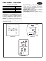
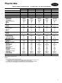
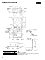
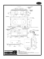
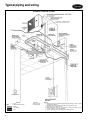
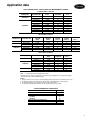
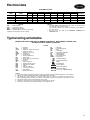
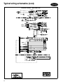
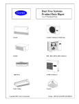
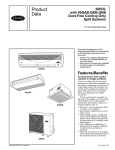
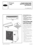
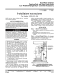
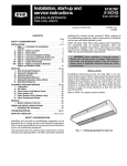
Product
Data
40QKB024,036
40QKE024,036,048
Cooling Only and
Heat Pump
In-Ceiling Cassettes
2 to 4 Nominal Tons
The 40QK Energy-Efficient In Ceiling
Cassette fan coil incorporates innovative technology to provide reliable performance. Built into these units are
features most desired by the industry
today, including SEER ratings of up to
11.3 when matched with Duct-Free
System Condensing units. All models
are listed with UL, UL, Canada, ARI,
and CEC. With a wide range of accessories available to meet a variety of
installation requirements, the 40QK
series is ideal for retrofits and
modernizations with suspended ceilings and can be installed in standard
2 ft x 2 ft and 2 ft x 4 ft grids.
Features/Benefits
40QKB,E024
Technology and components
The high-efficiency two or three-row
heat exchanger has mechanically
expanded copper tubes with continuous aluminum fins. The coil connections are made of brass.
Fan motor
The direct-drive fan with backward
curved blades has a three-speed permanent split capacitor motor with
built-in thermal protection, regulated
by an electronic thermostat. The
motor is installed on spring antivibration mounts. This fan blade design
ensures uniform airflow through the
heat exchanger.
Diffusers
40QKB,E036 and
40QKE048
Copyright 2004 Carrier Corporation
Four-way air distribution gives individual comfort. For localized control, each
diffuser may be adjusted or even shut
down completely. The special design
of the diffusers ensure rapid blending
of the supply and room air. Conditioned air is directed along the ceiling,
then evenly distributed throughout the
room. Return air enters the cassette
unit through a large grille. It is then
Form 40QK-1PD
cleaned by an easily removable, washable synthetic filter.
Controls
A choice of three different thermostats
is available, suitable for installation on
a wall. The Solid-State Electronic Thermostat is available in Slim Line (cooling
only, heat pump, heat and cool systems), Flat Stat (cooling only and heat
and cool systems) and a 5-1-1 Programmable (cooling only and heat and
cool systems). Thermostat features include three-speed manual setting or
Auto., and Auto. changeover.
Secure operation
Built-in reliability
If security is an issue, outdoor and
indoor units are connected only by
refrigerant piping and wiring to prevent intruders from crawling through
ductwork.
Carrier split system units are designed
to provide years of trouble-free operation with features such as freeze protection, branch ducting capability,
fresh air intake and 24-volt controls.
Fast installation
Carrier's compact systems take only a
few hours to install, since only wire and
piping need to be run. The fast and
easy installation ensures minimal disruption to customers in the home or
workplace. This is an added advantage
of Carrier's systems, especially in retrofit situations.
Model number nomenclature
40QK SERIES COOLING ONLY AND HEAT IN CEILING CASSETTES
40
QKB
024
3
Voltage
Indoor Fan Coil
Unit Type
QKB = Cassette Cool Only
QKE = Cassette Heat Pump
3 = 208/230-1-60
Nominal Capacity
024 = 2 Tons
036 = 3 Tons
048 = 4 Tons (QKE only)
Table of contents
Page
Features/Benefits . . . . . . . . . . . . . . . . . . . . . . . . . . . . . . . . . . . . . . . . . . .1,2
Model Number Nomenclature . . . . . . . . . . . . . . . . . . . . . . . . . . . . . . . . . . . 2
ARI Capacity Ratings . . . . . . . . . . . . . . . . . . . . . . . . . . . . . . . . . . . . . . . . . 3
Sound Ratings . . . . . . . . . . . . . . . . . . . . . . . . . . . . . . . . . . . . . . . . . . . . . . 3
Field-Installed Accessories . . . . . . . . . . . . . . . . . . . . . . . . . . . . . . . . . . . . . . 4
Physical Data . . . . . . . . . . . . . . . . . . . . . . . . . . . . . . . . . . . . . . . . . . . . . . . 5
Base Unit Dimensions . . . . . . . . . . . . . . . . . . . . . . . . . . . . . . . . . . . . . . . .6,7
Typical Piping and Wiring . . . . . . . . . . . . . . . . . . . . . . . . . . . . . . . . . . . . . . 8
Application Data . . . . . . . . . . . . . . . . . . . . . . . . . . . . . . . . . . . . . . . . . .9,10
Electrical Data . . . . . . . . . . . . . . . . . . . . . . . . . . . . . . . . . . . . . . . . . . . . . 11
Typical Wiring Schematics. . . . . . . . . . . . . . . . . . . . . . . . . . . . . . . . . . .11-14
Controls . . . . . . . . . . . . . . . . . . . . . . . . . . . . . . . . . . . . . . . . . . . . . . . . . 15
Guide Specifications . . . . . . . . . . . . . . . . . . . . . . . . . . . . . . . . . . . . . . .16,17
2
ARI* capacity ratings
ARI CAPACITIES IN-CEILING CASSETTE APPLICATIONS
40QKB IN-CEILING CASSETTES WITH 38HDC,HDL UNITS
INDOOR SECTION
OUTDOOR SECTION
38HDC018
38HDL018
38HDL030
38HDL036
38HDC024
38HDL024
38HDC030
38HDC036
40QKB024
40QKB036
STD CFM
525
525
915
915
915
915
915
915
COOLING (Btuh)
18,300
17,800
29,000
34,400
24,000
24,000
30,000
33,000
TOTAL kW
1.76
1.68
2.87
3.45
2.2
2.12
3.13
3.14
SEER
11
11.4
11.1
10.5
11
11.8
10.8
10.8
EER
10.4
10.8
10.4
9.9
10.9
11.3
9.6
10.5
40QKB IN-CEILING CASSETTES WITH 38HDS UNIT
INDOOR SECTION
40QKB024
OUTDOOR SECTION
38HDS024-3
STD CFM
24,000
COOLING (Btuh)
1,000
SEER
12.0
EER
11.3
CHARGE (lb)
4.1
HEATING kW
2.22
40QKE IN-CEILING CASSETTES WITH 38QR UNITS
INDOOR
SECTION
40QKE024
40QKE036
40QKE048
OUTDOOR
SECTION
38QR018C
38QR024C
38QR030C
38QR036C
STD
CFM
525
980
980
1100
COOLING
(Btuh)
18,000
25,000
29,000
33,000
TOTAL
kW
2
2.44
2.61
3.47
SEER
EER
10
10.7
11.5
10.5
9
10.2
11.1
9.5
HEATING
HIGH (Btuh)
17,600
23,800
27,000
33,000
HEATING
HIGH (COP)
3.04
3.34
3.27
3.3
HEATING
HIGH (HSPF)
6.8
7.6
7.6
6.8
HEATING
LOW (Btuh)
11,000
13,400
15,900
20,000
HEATING
LOW (COP)
2
2.3
2.3
2.2
40QKE IN-CEILING CASSETTES WITH 38HDC,HDL,HDS UNITS
INDOOR SECTION
40QKE024
40QKE024
40QKE036
40QKE048
ARI
COP
db
HSPF
wb
—
—
—
—
—
OUTDOOR SECTION
38HDC018-3
38HDL018-3
38HDS024-3
38HDC024-3
38HDL024-3
38HDC030-3
38HDL030-3
38HDC036-3,5,6
38HDL036-3
STD CFM
525
525
525
980
980
980
980
1100
1100
COOLING (Btuh)
17,800
17,800
23,000
23,800
24,000
29,800
29,000
33,800
34,800
LEGEND
Air Conditioning & Refrigeration Institute
Coefficient of Performance
Dry Bulb
Heating Seasonal Performance Factor
Wet Bulb
* 3-phase unit.
NOTES:
1. Ratings are net values reflecting the effects of circulating fan heat. Supplemental electric heat is not included. Ratings are based on:
SEER
10.5
11.2
12.0
11.5
11.0
12.0
10.9
11.5
10.3
EER
10.1
10.6
10.8
8.3
11.3
10.4
10.1
9.7
10.0
CHARGE (lb)
5.8*
3.9
4.1
4.8
4.6
5.2
5.6
5.8
6.0
HEATING kW
1.8
1.8
2.0
2.7
2.7
2.7
2.7
2.7
2.7
Cooling Standard: 80 deg F db, 67 deg F wb air entering evaporator and
95 deg F db air entering condenser.
High Temperature Heating Standard: 70 deg F db air entering evaporator and
47 deg F db, 43 F wb air entering condenser.
Low Temperature Heating Standard: 70 deg F db air entering evaporator and
17 deg F db, 15 F wb air entering condenser.
2. Total kW is for total system, including compressor and outdoor and indoor fan
motors.
3. Ratings are based on 25 ft of interconnecting refrigerant lines.
4. All system ratings are based on fan coil units operating at high fan speed.
Consult Physical Data tables for airflows at all available fan speeds.
Sound ratings
SOUND DATA (A Weighted)
UNIT
40QKB024
40QKB036
40QKE024
40QKE036
40QKE048
SOUND PRESSURE
(dBa)
FAN SPEED
SOUND POWER
(dBa)
45.3
39.9
38.8
43.8
37.2
29.9
45.3
—
—
43.8
37.2
29.9
48.1
42.9
—
High
Medium
Low
High
Medium
Low
High
Medium
Low
High
Medium
Low
High
Medium
Low
56.3
50.9
49.8
54.8
48.2
40.9
56.3
—
—
54.8
48.2
40.9
59.1
53.9
—
LEGEND
ARI — Air Conditioning and Refrigeration Institute
dBa — Decibels on the A Scale
125
32.1
42.0
40.9
45.0
35.5
31.2
32.1
—
—
45.0
35.5
31.2
40.2
45.0
—
SOUND POWER DATA OCTAVE BAND (dBa)
250
500
1000
2000
4000
45.0
51.2
54.1
46.5
45.0
44.1
48.0
47.5
42.2
37.3
43.0
46.9
46.4
41.1
36.2
45.8
50.9
51.8
47.4
38.8
40.2
46.1
45.2
39.0
29.9
37.8
40.3
37.0
26.5
24.5
45.0
51.2
54.1
46.5
45.0
—
—
—
—
—
—
—
—
—
—
45.8
50.9
51.8
47.4
38.8
40.2
46.1
45.2
39.0
29.9
37.8
40.3
37.0
26.5
24.5
45.8
54.8
56.0
51.5
47.7
47.1
51.0
50.5
45.2
40.3
—
—
—
—
—
8000
36.5
36.8
35.7
32.9
28.7
27.3
36.5
—
—
32.9
28.7
27.3
39.8
39.8
—
NOTES:
1. Sound power levels are tone corrected values taken in accordance with ARI
Sound Standard 350.
2. Sound pressure data is measured 1 m away from the unit.
3
Field-installed accessories
ACCESSORY PART NUMBERS
ACCESSORY
Slim Line Thermostat
Flat Stat Thermostat
NP - Thermostat
Discharge Grille (024)
Discharge Grille (036-048)
Fresh Air Intake Kit
Power Vent Fan for Fresh Air Intake
Remote Room Sensor Kit
PART NO.
53DFS250-SL
53DFS250-FS
53DFST2-NP
40QK900---215
40QK900---216
53DS-900---067
53DS-900---066
33CSSEN-WB
Slim Line thermostat is a specially designed programmable thermostat for Duct-Free Systems that incorporates
3-speed control, auto-changeover, backlight, locking keypad and large LCD (liquid crystal display). Can be used on
cooling only, heat pumps and heat cool systems.
Flat Stat is a specially designed programmable thermostat
for duct-free systems that incorporates 3-speed control,
auto-changeover, backlight, locking keypad and large LCD
and is mounted flush to the wall. Can be used on cooling
only and heat cool systems.
NP - Thermostat is a specially designed programmable
thermostat for Duct-Free Systems that incorporates
3-speed control, 5-1-1 day schedule, auto-changeover,
backlight, locking keypad and large LCD. Can be used on
cooling only and heat/cool systems.
Discharge grilles are required to allow air discharge and
return of room air for proper operation.
Fresh air intake kit provides for a variable amount of
outdoor air to be mixed with the conditioned air.
Power vent fan for fresh air intake allows up to 15%
outdoor air to be supplied to the conditioned space.
Remote room sensor kit is designed to sense the air
temperature at a remote location and send this information
by digital communication to the thermostat.
53DFST2-NP
53DFS250-SL
53DFS250-FS
4
Physical data
40QK IN-CEILING CASSETTE UNITS — COOLING ONLY AND HEAT PUMP MODELS
UNIT 40QK
NOMINAL CAPACITY (Tons)
OPERATING WEIGHT (lb)
MOISTURE REMOVAL (pts/hr)
REFRIGERANT TYPE
METERING DEVICE
CHARGE (Lb) Note #2
INDOOR FAN (Direct Drive)
High Rpm/Cfm
Med Rpm/Cfm
Low Rpm/Cfm
Air Throw ft (high fan)
Watts
Quantity
Hp
BLOWER WHEEL
Quantity
Size (in.)
INDOOR COIL DATA
Face Area (sq ft)
No. Rows
FPI
Circuits
FILTERS (Cleanable)
Quantity
Size (in.)
REFRIGERANT LINES
Connection Type
Liquid Line (in. OD)
Vapor Line (in. OD)
Max Length, Lift & Drop
CONDENSATE DRAIN
Connection
Size (in.)
CONTROLS (Solid State)
Wall Stat
Freeze Protection
Defrost Method
Warm Start
Auto Changeover
Auto Restart
Diagnostics
Timer Mode (Start/Stop)
Test Mode
Dehumidification Mode
Fan Speeds
Control Voltage
System Voltage
GRILLE FINISH
024
1.5
61.6
7
R-22
Note #3
Note #4
40QKB
036
3
105.8
9.6
R-22
AccuRater® Device
6.0
024
2
66.1
7
R-22
AccuRater Device
5.5
40QKE
036
3
105.8
8.6
R-22
AccuRater Device
5.9
048
4
118.8
9.6
R-22
AccuRater Device
5.9
1190/525
930/415
840/400
22
100
1
1/
16
970/915
790/745
635/635
20
180
2
1/
16
1190/525
930/430
840/400
22
100
1
1/
16
970/915
790/745
635/635
20
160
2
1/
16
1180/1100
920/ 880
830/ 680
20
180
2
1/
16
1
10 x 8
2
10 x 8
1
10 x 8
2
10 x 8
2
10 x 8
2.66
3
14
4
5.67
2
14
4
2.66
3
14
4
5.67
2
14
4
5.67
2
14
4
1
16.5 x 16.5
2
16.5 x 16.5
1
16.5 x 16.5
2
16.5 x 16.5
2
16.5 x 16.5
Flare
3/
8
5/
8
Note #1
Flare
3/
8
3/
4
Note #1
Flare
3/
8
5/
8
Note #1
Flare
3/
8
3/
4
Note #1
Flare
3/
8
3/
4
Note #1
Hose
1.0 dia
Hose
1.0 dia
Hose
1.0 dia
Hose
1.0 dia
Hose
1.0 dia
Yes
N/A
N/A
N/A
N/A
Yes
Yes†
24 Hr†
Yes
N/A
H/M/L/Auto
24 v
208/230 v
Ceiling White
Yes
N/A
N/A
N/A
N/A
Yes
Yes
24 Hr†
Yes
N/A
H/M/L/Auto
24 v
208/230 v
Ceiling White
Yes
Yes *
Time/Temp
N/A
Yes
Yes
Yes†
24 Hr†
Yes
N/A
H/M/L/Auto
24 v
208/230 v
Ceiling White
Yes
Yes *
Time/Temp
N/A
Yes
Yes
Yes†
24 Hr†
Yes
N/A
H/M/L/Auto
24 v
208/230 v
Ceiling White
Yes
Yes *
Time/Temp
N/A
Yes
Yes
Yes†
24 Hr†
Yes
N/A
H/M/L/Auto
24 v
208/230 v
Ceiling White
*Through outdoor unit low-pressure switch.
†With recommended thermostat.
NOTES:
1. See matching condenser for line lengths.
2. Cooling only units are shipped with a full factory charge in the outdoor unit based on 25 ft
of refrigerant lines. Heat Pump units are shipped with a holding charge.
3. AccuRater device when matched with 38HDC,HDL, TXV when matched with 38HDS.
4. When matched with 38HDC,HDL 4.8 lb. When matched with 38HDS 5.0 lb.
5
Base unit dimensions
40QKB,E024 IN-CEILING CASSETTE FAN COIL UNITS
UNIT
40QKB024 (Without Heaters)
40QKE024 (With Heaters)
6
WEIGHT
Lb
Kg
61.6
28
66.1
30
NOTES:
1.
2.
3.
4.
5.
6.
Indicates airflow.
Dimensions in [ ] are in millimeters.
Service clearance is 2 ft on control box side, zero in. all other sides.
Air discharge slots are adjustable; 1 or 2 may be closed to direct air in the desired direction.
Grille is shipped separately from unit.
Condensate pump has 20 in. lift capability.
40QKB036 AND 40QKE036,048 IN-CEILING CASSETTE FAN COIL UNITS
UNIT
40QKB036
40QKE036
40QKE048
WEIGHT
Lb
Kg
105.8
48
114.4
52
118.8
54
NOTES:
1.
2.
3.
4.
5.
6.
Indicates airflow.
Dimensions in [ ] are in millimeters.
Service clearance is 2 ft on control box side, zero in. all other sides.
Air discharge slots are adjustable; 1 or 2 may be closed to direct air in the desired direction.
Grille is shipped separately from unit.
Condensate pump has 20 in. lift capability.
7
Typical piping and wiring
IN-CEILING CASSETTE SYSTEM
NEC
8
φ
LEGEND
— Phase
— National Electrical Code
Piping
Line Voltage
24 V
*Standard.
†Accessory item.
**Field supplied.
NOTES:
1. All piping must follow standard refrigerant piping techniques. Refer to Carrier
System Design Manual.
2. All wiring must comply with the applicable local and national codes.
3. Liquid line need not be insulated.
4. Wiring and piping shown are general points-of-connection guides only and
are not intended for a specific installation.
5. Insulate condensate drain if installed in a conditioned space.
Application data
UNIT COMBINATIONS, PISTON SIZE AND REFRIGERANT CHARGE
COOLING ONLY CASSETTE
INDOOR UNIT
OUTDOOR UNIT
38HDC018-3
38HDL018-3
38HDC024-3
38HDL024-3
38HDC030-3
38HDL030-3
38HDC036-3
38HDC036-5
38HDC036-6
38HDL036-3
40QKB024†
40QKB036
ARI CAPACITY*
(Btuh)
18,300
17,800
24,000
24,000
30,000
29,000
33,000
33,000
33,000
34,400
ACCURATER®
PISTON NO.
52
52
62
62
63
63
65
65
65
65
CHARGE (lb)
NOTE 1
4.8**
3.9
5.4
4.6
5.2
5.6
6.0**
6.0**
6.0**
6.0**
HEAT PUMP CASSETTE
INDOOR UNIT
OUTDOOR UNIT
40QKE024
38QR-018C-3
38QR-024C-3
38QR-030C-3
38QR-036C-3
38QR-036C-5
38QR-036C-6
40QKE036
40QKE048
ARI CAPACITY*
COOLING
(Btuh)
18,000
25,000
29,000
32,000
32,000
32,000
ARI CAPACITY*
HEATING
(Btuh)
17,600
23,800
27,000
33,000
33,000
33,000
ACCURATER
PISTON
(Indoor)
51
61
63
67
67
67
ACCURATER
PISTON
(Outdoor)
49
49
55
59
59
59
CHARGE (lb)
NOTE 1
5.5
5.9
5.9
5.9
8.0
8.0
HEAT/COOL CASSETTE
INDOOR UNIT
40QKE024
40QKE036
40QKE048
*ARI
OUTDOOR UNIT
38HDC018-3
38HDL018-3
38HDC024-3
38HDL024-3
38HDC030-3
38HDL030-3
38HDC036-3,5,6
38HDL036-3
ARI CAPACITY*
(Btuh)
17,800
17,800
23,800
24,000
29,800
29,000
33,800
34,000
ACCURATER
PISTON NO.
52
52
62
62
63
63
67
67
CHARGE (lb)
NOTE 1
5.8**
3.9
4.8
4.6
5.2
5.6
5.8
6.0
LEGEND
— Air Conditioning and Refrigeration Institute
†The 024 size unit shown is configured as an 018 size unit changing the motor speed fan tap plug.
**Combination may require additional charge.
NOTES:
1. Charge is based on 25 ft of interconnecting tubing. Charge may need to be added for longer runs.
2. Cooling units shipped with a full charge. Heat Pumps are shipped with a holding charge.
3. For expanded ratings see matching condenser product data catalog.
4. Air entering evaporator 80 F dry bulb. Air entering evaporator 72 F wet bulb.
SYSTEM OPERATING CONDITIONS
FAN COIL UNIT (40QK)
Maximum Room Temperature
Minimum Room Temperature
Maximum Return Air
Dry-Bulb
Wet-Bulb
Minimum Return Air (Heat Pump)
Maximum Saturated Suction Temperature
Minimum Saturated Suction Temperature
TEMP (F)
95
55
85
72
28
55
27
9
Application data (cont)
Fresh air and ducting
The in-ceiling cassette fan coil units may bring in up to
20% fresh air. This 20% maximum should not be exceeded. A power ventilation kit is available to overcome ventilation duct static. See Power Ventilation Kit Available Static
Pressure table below.
The in-ceiling cassette fan coil units may have an
extension duct installed. See Static Capability and Design
Considerations figure on this page.
POWER VENTILATION KIT AVAILABLE STATIC PRESSURE
FAN
HP
1/
15
WATTS
150
RPM
2700
VOLTAGE
208/230
0
370
1/
8
335
CFM AT STATIC PRESSURE (in. wg)
1/
3/
1/
3/
4
8
2
4
318
298
256
219
STATIC CAPABILITY AND DESIGN CONSIDERATIONS
ONE DIFFUSER CLOSED
TWO DIFFUSERS CLOSED
PATH FOR RETURN AIR
10
1
189
11/2
112
DUCT
DIA. (in.)
6
Electrical data
ELECTRICAL DATA
UNIT
40QK
VOLTS-PHASE
(60 Hz)
B024-3
B036-3
E024-3
E036-3
E048-3
208/230-1
208/230-1
208/230-1
208/230-1
208/230-1
FLA
LRA
MCA
MOCP
—
—
—
—
VOLTAGE
Min
Max
187
253
187
253
187
253
187
253
187
253
FAN
FLA
0.44
0.44
0.44
0.78
1.04
LEGEND
Full Load Amps
Locked Rotor Amps
Minimum Circuit Amps
Maximum Overcurrent Protection Amps
*Separate unit and heater circuits required.
HEATER
kW
FLA
—
—
—
—
1.80*
7.50
2.70*
11.25
2.70*
11.25
MCA
0.55
1.10
0.6/9.4
1.0/15.0
1.3/15.0
POWER SUPPLY
MOCP
FLA
15
0.44
15
0.88
15/15
7.94
15/15
12.80
15/15
12.03
MINIMUM
WIRE SIZE
14
14
14/14
14/14
14/14
NOTES:
1. Two MCA, MOCP, and minimum wire size values are shown for units
with separate unit and heater circuits.
The first value applies to the unit circuit and the second applies to
the heater circuit.
2. Two fan motors are used on the 40QKB036, 40QKE036 and
40QKE048 units.
Typical wiring schematics
LEGEND AND NOTES FOR TYPICAL WIRING SCHEMATICS, 40QK SERIES COOLING ONLY
AND HEAT PUMP IN-CEILING CASSETTES
LEGEND
C
CAP
CCHT
CH
CLO
COMP
CR
CT
DR
FPT
FR
GND
HC
HLC
HPS
HTR
IFM
LPS
LS
OFM
—
—
—
—
—
—
—
—
—
—
—
—
—
—
—
—
—
—
—
—
Contactor
Capacitor
Crankcase Heater Thermostat
Crankcase Heater
Compressor Lockout
Compressor
Control Relay
Current Transformer
Delay Relay
Freeze Protection Thermostat
Fan Relay
Ground
Heater Contactor
Heating Limit Contactor
High-Pressure Switch
Heater
Indoor Fan Motor
Low-Pressure Switch
Limit Switch
Outdoor-Fan Motor
OL
PDR
PL
PM
PSS
ST
TB
TDR
TRAN
—
—
—
—
—
—
—
—
—
Overload
Pump Delay Relay
Plug
Pump Motor
Pump Shut-off Switch
Start Thermistor
Terminal Block
Time Delay Relay
Transformer
Terminal (Marked)
Terminal (unmarked)
Splice
Terminal Block
Factory Wiring
Field Control Wiring
Field Power Wiring
Accessory or Optional Wiring
NOTES:
1. If any of the original wire furnished must be replaced, it must be replaced with type 90 C wire or its equivalent.
2. Wire in accordance with National Electrical Code (NEC) and local codes.
3. The CLO locks out the compressor to prevent short cycling on compressor overloads and safety devices.
Before replacing CLO, check these other devices. A minimum 1 amp turn is required to hold contacts closed.
4. A thermistor wiring cable is provided with the fan coil unit.
5. Compressor and fan motors are protected by internal thermal overloads.
6. Transformer has an internal 2 amp thermal fuse on the primary side.
11
Typical wiring schematics (cont)
CASSETTE SYSTEM — COOLING ONLY
12
CASSETTE SYSTEM — HEAT PUMP
13
Typical wiring schematics (cont)
CASSETTE SYSTEM — HEAT AND COOL
14
Controls
Operating mode memory
After the system is turned off or after a power failure, the
system remains in the last operating mode selected. When
the system is turned back on, or when power is automatically restored, operation continues in the same operating
mode as when the system shut down.
Automatic operation (auto) mode
If auto mode is selected, the system automatically switches
over the operating mode from heating to cooling, or
from cooling to heating depending on the selected temperature. Auto. mode also controls fan speed if not manually
overridden.
NOTE: Between the cooling cycle and the heating cycle
there is a neutral zone of approximately 2° F above and
2° F below the selected temperature when only the fan is
operating.
Operating sequence
The fan coil units have a terminal board which controls system operation in response to the room thermostat. The
user may manually select any one of 3 fan speeds for unit
operation. Systems may be equipped with an accessory
power ventilation kit and have a factory-installed condensate pump.
Fan operation — See selected Thermostat instructions
for fan operation controls.
Cooling mode operation — When the room thermostat
senses a demand for cooling, the fan coil relay board is
energized. The indoor fan(s) will start in the selected speed.
The reversing valve will energize and switch to the cooling
position. The internal condensate pump runs whenever
the reversing valve is energized and/or the unit is in cooling. As long as the condensate float switch and freeze protection thermostat are closed, the cooling relays in the fan
coil unit will close. This energizes the compressor and outdoor fan in the outdoor unit. The compressor will continue
to operate until the room thermostat is satisfied. When the
cooling demand is satisfied, the compressor and outdoor
fan will stop. If the system is in the AUTO mode, the
indoor fan will stop with the compressor. If the unit has the
accessory ventilation kit, the ventilation fan will operate
whenever the indoor fan is set for medium or high speed.
Heat pump operation — When the room thermostat
senses a demand for heating, the fan coil relay board is
energized. The indoor fan will start in the selected speed (if
not already operating), and the reversing valve will not be
energized. The internal condensate pump and freeze
protection thermostat are not operated during heating
operation. The control relay closes, and the compressor
and outdoor fan are energized through the defrost board
(DFB), which is located in the outdoor unit. The logic in the
DFB is energized when the compressor starts, and the
defrost timer runs. Once every 90 minutes (factory default
setting) of compressor run time, the DFB logic checks the
defrost thermostat (DFT). If the DFT is open, the unit continues in heating operation. If the DFT is closed, the DFB
switches the unit to defrost mode. The timing on the DFB
may be set at either 30, 50, or 90 minutes.
Defrost — The DFB energizes the RVS (reversing valve
solenoid), and the reversing valve energizes and switches to
the cooling position. The relay on the DFB opens and the
outdoor fan stops. The contact on the DFB is also energized, which in turn energizes the defrost relay on the fan
coil relay board, turns off the electric heater and stops
the indoor fan. The DFB logic checks the 10-minute
defrost timer and the DFT. If the DFT opens in less than
10 minutes, the DFB switches the unit back to normal
heating operation. If the DFT remains closed the
DFB switches the unit back to heating operation after
10 minutes. When the DFB changes back to heating
mode, the RVR (reversing valve relay) is deenergized and
the reversing valve switches back to heating operation.
Both the outdoor and indoor fans come back on, and if
necessary, the electric heater also turns on.
System safeties — The system is equipped with the following safety devices to protect system components:
Indoor coil freeze protection thermostat (cooling cycle
only) — If a coil temperature of 28 F or lower is sensed,
the compressor and outdoor fan will be shut down until the
coil temperature exceeds 28 F. The indoor fan will continue to run.
Condensate float switch — If the level of condensate in the
drain pan rises too high, the condensate float switch will
turn off the compressor and outdoor fan until the condensate level returns to normal. The indoor fan will continue
to run.
Special operation, heating — Outdoor cooling units
can be matched with heat pump indoor fan coil units to
provide supplemental electric heat. All other operation is
the same as a cooling only system, except these units have
heating capability as follows: When the room thermostat
initiates a call for heating, the electric heater is turned on.
The indoor unit fan will start at the same time if it was not
already running. When the heating requirement is satisfied,
the room thermostat will open, and the heater will turn off.
15
Guide specifications
In-Ceiling Cassette Cooling Only Units
HVAC Guide Specifications
Size Range: 2 to 3 Tons Cooling Capacity
Carrier Model Number: 40QKB
Part 1 — General
1.01 SYSTEM DESCRIPTION
Indoor, in-the-ceiling-mounted, direct-expansion fan
coil. Units shall fit standard 2 ft x 2 ft and 2 ft x 4 ft
ceiling grid.
1.02 QUALITY ASSURANCE
Unit shall be rated (when matched with appropriate
outdoor unit) per ARI Standards 210/240. Units
shall be certified by UL for sale in the USA and
Canada.
1.03 DELIVERY, STORAGE, AND HANDLING
Units shall be stored and handled per unit manufacturer’s recommendations.
1.04 WARRANTY
One-year parts.
Part 2 — Products
2.01 EQUIPMENT
A. General:
Indoor, direct-expansion, low-profile (113/4-in. high)
in-ceiling fan coil. Fan coil shall be shipped complete
with cooling coil, fan, fan motor, piping connectors,
electrical controls, condensate pump, and hanging
brackets. The grille is sold as a separate item.
B. Unit Cabinet:
Indoor cabinet shall be constructed of zinc-coated
steel. Fully insulated discharge and inlet grilles shall
be attractively styled, high-impact polystyrene. Cabinet shall have filter tracks and cleanable filters which
shall be accessible from below with a 1/4-turn fastener. Adjacent room cooling to be provided by a
simple knockout in the cabinet side panel, and cabinet shall have provisions to accommodate a limited
amount of ductwork, if desired.
C. Fans:
Indoor fan shall be 3-speed centrifugal, direct-drive
blower type with air intake in center of the unit and
discharge on the perimeter. Air louvers shall be
adjustable for 2, 3, or 4-way discharge.
16
D. Coil:
Coil shall be copper tube with aluminum fins and
galvanized steel tube sheets. Fins shall be bonded to
the tubes by mechanical expansion. A drip pan
under the coil shall have a factory-installed condensate pump and drain connection for hose attachment to remove condensate.
E. Refrigerant Metering Device:
The unit shall have a refrigerant metering piston and
body.
F. Motors:
Motors shall be totally enclosed and permanently
lubricated with inherent overload protection.
G. Controls:
Controls shall be 24 v, and shall be easily operated
by the user from a wall-mounted thermostat. Float
control shall be in the condensate sump to shut unit
down in case of pump malfunction. The wallmounted thermostat will have 3 fan speed selections, and an auto. mode. The thermostat is sold as
a separate item. The R-22 refrigerant is controlled
with a piston-type refrigerant metering device, and
evaporator coil freeze protection shall be provided.
H. Filters:
Unit shall have factory-supplied cleanable filters.
I. Electrical Requirements:
Unit shall operate on 208/230 v, 60 Hz power supply as specified on the equipment schedule. Power
and control connections shall have terminal block
connections.
J. Special Features (Field Installed):
1. Fresh Air Intake Kit:
Kit shall include filter and duct connections to
provide for outdoor ventilation air.
2. Power Ventilation Kit:
Kit must be used with the accessory fresh air kit
when fresh air must be ducted in. The kit will
overcome duct static to provide a constant supply of ventilation air. Kit consists of booster fan
and adjustable speed control to properly balance fan to achieve required airflow rate.
3. Remote Room Sensor Kit:
Kit shall sense the air temperature at a remote
location and send information by digital communication to the thermostat.
In-Ceiling Cassette Heat Pump Units
HVAC Guide Specifications
Size Range: 2 to 4 Tons Cooling Capacity
Carrier Model Number: 40QKE
Part 1 — General
1.01 SYSTEM DESCRIPTION
Indoor, in-the-ceiling-mounted, direct-expansion fan
coil. Units shall fit standard 2 ft x 2 ft and 2 ft x 4 ft
ceiling grid.
1.02 QUALITY ASSURANCE
Unit shall be rated (when matched with appropriate
outdoor unit) per ARI Standards 210/240. Units
shall be certified by UL for sale in the USA and Canada
1.03 DELIVERY, STORAGE, AND HANDLING
Units shall be stored and handled per unit manufacturer’s recommendations.
1.04 WARRANTY
One-year parts.
Part 2 — Products
2.01 EQUIPMENT
A. General:
Indoor, direct-expansion, low-profile (113/4-in. high)
in-ceiling fan coil. Fan coil shall be shipped complete
with cooling coil, fan, fan motor, piping connectors,
electrical controls, condensate pump, and hanging
brackets. The grille is sold as a separate item.
B. Unit Cabinet:
Indoor cabinet shall be constructed of zinc-coated
steel. Fully insulated discharge and inlet grilles shall
be attractively styled, high-impact polystyrene. Cabinet shall have filter tracks and cleanable filters which
shall be accessible from below with a 1/4-turn fastener. Adjacent room cooling to be provided by a
simple knockout in the cabinet side panel, and cabinet shall have provisions to accommodate a limited
amount of ductwork, if desired.
C. Fans:
Fan shall be 3-speed centrifugal, direct-drive blower
type with air intake in center of the unit and discharge on the perimeter. Air louvers shall be adjustable for 2,3, or 4-way discharge.
D. Coil:
Coil shall be copper tube with aluminum fins and
galvanized steel tube sheets. Fins shall be bonded to
the tubes by mechanical expansion. A drip pan
under the coil shall have a factory-installed condensate pump and drain connection for hose attachment to remove condensate.
E.
F.
G.
H.
I.
J.
NOTE: The units use the AccuRater® piston refrigerant metering device in the indoor unit (for cooling)
and at the outdoor unit liquid line service valve (for
heating).
Motors:
Motors shall be totally enclosed and permanently
lubricated with inherent overload protection.
Electric Heater:
Units shall be equipped with factory-mounted electric heaters. Minimum protections shall include
overcurrent and high temperature protection.
Controls:
Controls shall be 24 v, and shall be easily operated
by the user from a wall-mounted thermostat. Float
control shall be in the condensate sump to shut unit
down in case of pump malfunction. The wallmounted thermostat will have 3 fan speed selections, and an auto. mode and is sold as a separate
item. The R-22 refrigerant is controlled with a piston-type refrigerant metering device, and evaporator
coil freeze protection shall be provided.
Filters:
Unit shall have factory-supplied cleanable filters.
Electrical Requirements:
Unit shall operate on 208/230 v, 60 Hz power supply as specified on the equipment schedule. Power
and control connections shall have terminal block
connection.
Special Features (Field Installed):
1. Fresh Air Intake Kit:
Kit shall include filter and duct connections to
provide for outdoor ventilation air (must be used
with Power Ventilation Kit).
2. Power Ventilation Kit:
Kit must be used with the accessory fresh air kit
when fresh air must be ducted in. The kit will
overcome duct static to provide a constant supply of ventilation air. Kit consists of booster fan
and adjustable speed control to properly balance fan to achieve required airflow rate.
3. Remote Room Sensor Kit:
Kit shall sense the air temperature at a remote
location and send information by digital communication to the thermostat.
17
18
19
Carrier Corporation • Syracuse, New York 13221
9-04
Manufacturer reserves the right to discontinue, or change at any time, specifications or designs without notice and without incurring obligations.
Book 2
Book 1 4
New
Pg 20
Catalog No. 524-082
Printed in U.S.A.
PC 111
Form 40QK-1PD
Replaces: New
Tab 2DF
Tab 3e 2f