1
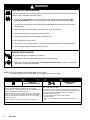
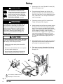
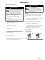
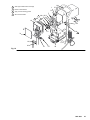
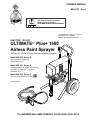
OWNER’S MANUAL
824–033 Rev A
This manual contains important
warnings and information.
READ AND RETAIN FOR REFERENCE
U.S. PATENT NO. 4,323,741, 4,397,610
PATENTED 1983, CANADA
AND OTHER PATENTS PENDING
ELECTRIC, 120 VAC
ULTIMATE Plus+ 1500
Airless Paint Sprayer
3000 psi (21.0 MPa, 210 bar) Maximum Working Pressure
Model 824–030, Series A
Basic sprayer on upright cart
without hose or gun
Model 824–031, Series A
Complete sprayer on upright cart with hose,
gun, RAC IV DripLess Tip Guard
and SwitchTip
Model 824–032, Series A
Same as Model 824–030, except
Patents Pending
The SHERWIN-WILLIAMS COMPANY, CLEVELAND, OHIO 44115
Table of Contents
Warnings . . . . . . . . . . . . . . . . . . . . . . . . . . . . . . . . . . . . . . 2
Setup . . . . . . . . . . . . . . . . . . . . . . . . . . . . . . . . . . . . . . . . . 6
Operation . . . . . . . . . . . . . . . . . . . . . . . . . . . . . . . . . . . . . 7
Flushing . . . . . . . . . . . . . . . . . . . . . . . . . . . . . . . . . . . . . 10
Troubleshooting . . . . . . . . . . . . . . . . . . . . . . . . . . . . . . . 11
Motor Brush Replacement . . . . . . . . . . . . . . . . . . . . . . 13
Removing and Installing Pump . . . . . . . . . . . . . . . . . . 15
Pressure Control . . . . . . . . . . . . . . . . . . . . . . . . . . . . . . 16
Pressure Control Repair . . . . . . . . . . . . . . . . . . . . . . . . 17
Motor . . . . . . . . . . . . . . . . . . . . . . . . . . . . . . . . . . . . . . . . 20
Bearing Housing & Connecting Rod . . . . . . . . . . . . .
Drive Housing Replacement . . . . . . . . . . . . . . . . . . . .
Sprayer Parts Drawing . . . . . . . . . . . . . . . . . . . . . . . . .
Sprayer Parts List . . . . . . . . . . . . . . . . . . . . . . . . . . . . .
Hose and Gun Parts Drawing and List . . . . . . . . . . .
Accessories . . . . . . . . . . . . . . . . . . . . . . . . . . . . . . . . . .
Technical Data . . . . . . . . . . . . . . . . . . . . . . . . . . . . . . . .
Dimensions . . . . . . . . . . . . . . . . . . . . . . . . . . . . . . . . . . .
22
23
24
25
26
30
31
31
Symbols
Warning Symbol
Caution Symbol
WARNING
CAUTION
This symbol alerts you to the possibility of serious
injury or death if you do not follow the instructions.
This symbol alerts you to the possibility of damage to
or destruction of equipment if you do not follow the
instructions.
WARNING
EQUIPMENT MISUSE HAZARD
Equipment misuse can cause the equipment to rupture or malfunction and result in serious injury.
INSTRUCTIONS
D This equipment is for professional use only.
D Read all instruction manuals, tags, and labels before operating the equipment.
D Use the equipment only for its intended purpose. If you are uncertain about usage, call your
Graco distributor.
D Do not alter or modify this equipment. Use only genuine Graco parts and accessories.
D Check equipment daily. Repair or replace worn or damaged parts immediately.
D Do not exceed the maximum working pressure of the lowest rated system component. Refer to
the Technical Data on page 31 for the maximum working pressure of this equipment.
D Use fluids and solvents which are compatible with the equipment wetted parts. Refer to the
Technical Data section of all equipment manuals. Read the fluid and solvent manufacturer’s
warnings.
D Do not use hoses to pull equipment.
D Route hoses away from traffic areas, sharp edges, moving parts, and hot surfaces. Do not expose Graco hoses to temperatures above 180_F (82_C) or below –40_F (–40_C).
D Do not lift pressurized equipment.
D Comply with all applicable local, state, and national fire, electrical, and safety regulations.
WARNING
INJECTION HAZARD
Spray from the gun, leaks or ruptured components can inject fluid into your body and cause extremely serious injury, including the need for amputation. Fluid splashed in the eyes or on the skin
can also cause serious injury.
Fluid injected into the skin is a serious injury. The injury may look like just a cut, but it is a serious
injury. Get immediate medical attention.
Do not point the gun at anyone or at any part of the body.
Do not put your hand or fingers over the spray tip.
Do not stop or deflect leaks with your hand, body, glove or rag.
Do not “blow back” fluid; this is not an air spray system.
Always have the tip guard and the trigger guard on the gun when spraying.
Check the gun diffuser operation weekly. Refer to the gun manual.
Be sure the gun trigger safety operates before spraying.
Lock the gun trigger safety when you stop spraying.
Follow the Pressure Relief Procedure on page 7 if the spray tip clogs and before cleaning,
checking or servicing the equipment.
Tighten all fluid connections before operating the equipment.
Check the hoses, tubes, and couplings daily. Replace worn or damaged parts immediately. Do
not repair high pressure couplings; you must replace the entire hose.
Fluid hoses must have spring guards on both ends, to help protect them from rupture caused by
kinks or bends near the couplings.
TOXIC FLUID HAZARD
Hazardous fluid or toxic fumes can cause serious injury or death if splashed in the eyes or on the
skin, inhaled, or swallowed.
Know the specific hazards of the fluid you are using.
Store hazardous fluid in an approved container. Dispose of hazardous fluid according to all local,
state and national guidelines.
Always wear protective eyewear, gloves, clothing and respirator as recommended by the fluid
and solvent manufacturer.
WARNING
FIRE AND EXPLOSION HAZARD
Improper grounding, poor ventilation, open flames or sparks can cause a hazardous condition and
result in a fire or explosion and serious injury.
If there is any static sparking or you feel an electric shock while using this equipment, stop
spraying immediately. Do not use the equipment until you identify and correct the problem.
Provide fresh air ventilation to avoid the buildup of flammable fumes from solvents or the fluid
being sprayed.
Keep the spray area free of debris, including solvent, rags, and gasoline.
Electrically disconnect all equipment in the spray area.
Extinguish all open flames or pilot lights in the spray area.
Do not smoke in the spray area.
Do not turn on or off any light switch in the spray area while operating or if fumes are present.
Do not operate a gasoline engine in the spray area.
MOVING PARTS HAZARD
Moving parts can pinch or amputate your fingers.
Keep clear of all moving parts when starting or operating the pump.
Before servicing the equipment, follow the Pressure Relief Procedure on page 7 to prevent the
equipment from starting unexpectedly.
NOTE: This is an example of the DANGER label on your sprayer.
This label is available in other languages, free of charge. See page 30 to order.
FIRE AND
EXPLOSION HAZARD
Spray painting, flushing or cleaning equipment with flammable
liquids in confined areas can result in fire or explosion.
Use outdoors or in extremely well ventilated areas. Ground equipment,
hoses, containers and objects being sprayed.
Avoid all ignition sources such as static electricity from plastic drop
cloths, open flames such as pilot lights, hot objects such as cigarettes,
arcs from connecting or disconnecting power cords or turning light
switches on and off.
Failure to follow this warning can result in death or serious injury.
SKIN INJECTION
HAZARD
Liquids can be injected into the body by high pressure airless spray or
leaks – especially hose leaks.
Keep body clear of the nozzle. Never stop leaks with any part of the
body. Drain all pressure before removing parts.Avoid accidental triggering of gun by always setting safety latch when not spraying.
Never spray without a tip guard.
In case of accidental skin injection, seek immediate
“Surgical Treatment”.
Failure to follow this warning can result in amputation or serious
injury.
READ AND UNDERSTAND ALL LABELS AND INSTRUCTION MANUALS BEFORE USE
Major Components
A
S
D
K
0137
E
M
T
F
G
H
J
U
P
R
L
B
7148A
7387A
C
N
Fig. 1
A
Motor (Under shield shown)
DC motor, 120 Vac, 60 Hz, 18A, 1 phase
B
Pressure Adjusting Knob
Controls fluid outlet pressure
C
ON/OFF Switch
Power switch that controls 120 Vac power to sprayer
D
Drive Assembly
Transfers power from DC motor to the displacement pump
E
Fluid Filter
Filter of fluid between source and spray gun
F
Secondary Fluid Outlet
Second spray gun operation is connected here
G
Pail Hanger
Container for fluid to be sprayed may be hung here
H
Displacement Pump
Pressures fluid to be sprayed through spray gun
J
50 ft. (15 m) Main Hose
1/4 in. ID, grounded, nylon hose with spring guards on both ends
K
RAC IV Tip Guard
Reverse-A-Clean (RAC) tip guard reduces the risk of fluid injection injury
L
Contractor Gun
High pressure spray gun with gun safety latch
M
RAC IV SwitchTip
RAC SwitchTip atomizes fluid and removes clogs from spray tip without
removing tip from spray gun
N
3 ft. (0.9 m) Hose
3/16 in. ID, grounded, nylon hose used between 50 ft. hose and spray gun
to allow more flexibility when spraying
P
Pressure Drain Valve
Relieves fluid pressure when open
R
Pressure Control
Controls motor speed to maintain fluid pressure. Works with pressure adjusting knob.
S
Spray Gun Safety Latch
Inhibits accidental triggering of spray gun
T
Primary Fluid Outlet
Hose and spray gun is connected here
U
15/20 Amp Switch
Allows sprayer to operate on 15A service with reduced performance
Setup
1. Connect gun, 3 ft. hose (78) and 50 ft. hose (79).
Don’t install spray tip yet.
WARNING
FIRE AND EXPLOSION HAZARD
Proper electrical grounding is essential
to reduce the risk of fire or explosion
which can result in serious injury and
property damage. Also read FIRE OR
EXPLOSION HAZARD on page 4.
2. Two gun hookup. Remove cap (12) from 1/4
npsm(m) secondary hose outlet and attach minimum 50 ft. long hose. For more flexible gun movement, install 3/16 in. ID, 3 ft. whip hose between
main hose and gun.
3. Fill packing nut/wet–cup (E)1/3 full with Graco
Throat Seal Liquid (TSL), supplied.
WARNING
If you supply your own hoses and spray gun, be
sure the hoses are electrically conductive, that
the gun has a tip guard, and that each part is
rated for at least 3000 psi (21.0 MPa, 210 bar )
Working Pressure. This is to reduce the risk of
serious injury caused by static sparking, fluid
injection or over-pressurization and rupture of
the hose or gun.
4. Check electrical service. Be sure electrical service
is 120 Vac, 60 Hz, 20 A. Use properly grounded
outlet. Do not remove grounding prong of power
supply cord or of any extension cords used. Do not
use an adapter. Extension cords must have 3
wires of minimum 12 gauge size. Long extension
cords reduce sprayer performance. If 20 amp
service is not available, set 15/20 amp switch (C)
to 15 amp to avoid nuisance tripping of circuit
breakers.
CAUTION
To avoid damaging the pressure control, which may
result in poor equipment performance and component damage, follow these precautions:
5. With ON/OFF switch (A) set to OFF, plug cord into
a grounded electrical outlet located at least 20 ft.
(6 m) away from spray area. See Fig. 2
1. Always use a nylon spray hose at least 50 ft.
(15 m) long.
6. Flush pump to remove lightweight oil which was
left in to protect pump parts after factory testing.
See page 10.
2. Never use a wire braid hose as it is too rigid to
act as a pulsation dampener.
3. Never install any shutoff device between the
sprayer outlet (D) and the hose. See Fig. 2.
C
78
12
2
E
79
7148A
D
A
B
55
7388A
1
Do not install any shutoff device here
2
Fill packing nut 1/3 full with TSL
Fig. 2
118
1
Operation
Pressure Relief Procedure
WARNING
WARNING
PRESSURIZED EQUIPMENT HAZARD
The system pressure must be manually
relieved to prevent the system from
starting or spraying accidentally. To
reduce the risk of an injury from accidental spray
from the gun, splashing fluid, or moving parts,
follow the Pressure Relief Procedure whenever
you:
are instructed to relieve the pressure,
stop spraying,
check or service any of the system equipment,
or install or clean the spray nozzle.
INJECTION HAZARD
To reduce the risk of serious injury,
whenever you are instructed to relieve
pressure, follow the Pressure Relief
Procedure above.
Startup
Always use this procedure to help ensure sprayer is
ready to operate and that you start it safely. See
Fig. 2
1. For a first time startup, flush sprayer. See page 10.
2. Close pressure drain valve (118).
3. Don’t install spray tip until pump is primed!
1. Engage gun safety latch.
2. Turn ON/OFF switch to OFF.
3. Unplug power cord.
4. Disengage gun safety latch. Hold metal part of gun
against grounded metal pail and trigger gun into
pail to relieve pressure.
4. Put suction tube into paint container.
5. Lower pressure setting by turning pressure adjusting knob (B) all the way counterclockwise.
6. Disengage gun safety latch. See Fig. 3.
Gun safety latch
shown engaged
Gun safety latch
shown disengaged
5. Engage gun safety latch.
6. Open any fluid drain valves in system. Leave drain
valve open until ready to dispense again.
Fig. 3
Operation
7. To prime pump, hold a metal part of gun firmly
against into a metal waste container. See Fig. 4.
Squeeze trigger and hold it open, turn ON/OFF
switch to ON, and slowly increase pressure setting
until sprayer starts. Keep gun triggered until all air
is forced out of system and paint flows freely from
gun. Release trigger and engage gun safety latch.
11. Adjust pressure.
a. Turn pressure adjusting knob clockwise until
spray from gun is just completely atomized. To
avoid excessive overspray and fogging, and to
decrease tip wear and extend life of sprayer,
always use lowest possible pressure needed
to get desired results.
CAUTION
b. If more coverage is needed, use larger tip
rather than increasing pressure.
Do not run the sprayer dry for more than 30 seconds
to avoid damaging the pump packings.
c.
8. Check all fluid connections for leaks. If any leaks
are found, relieve pressure before tightening
connections.
WARNING
FIRE AND EXPLOSION HAZARD
To reduce the risk of fluids entering
control box, check weep hole (Fig.16, C)
regularly. Replace o–ring when any
leakage is seen. Also read FIRE OR
EXPLOSION HAZARD on page 4.
Test spray pattern. To adjust direction of spray
pattern: engage gun safety latch, loosen
retaining nut, position tip guard horizontally for
horizontal pattern or vertically for vertical
pattern then tighten retaining nut.
Maintain firm metal–to–metal
contact between gun and
grounded pail when flushing
9. Check weep hole (Fig. 16, C) of pressure control
for leakage at start up and during operation. If
leakage, replace o–ring as instructed in Pressure
Control Transducer and O–Ring Replacement on
page 17.
10. Engage gun safety latch. Install spray tip. If you
are using RAC IV tip guard, refer to manual
308–644 for installation instructions.
Fig. 4
Operation
Cleaning a Clogged Tip
Shutdown and Care
1. Check packing nut/wet–cup daily. Relieve pressure. Keep packing nut/wet–cup (A) 1/3 full with
TSL at all times to help prevent fluid buildup on
piston rod and premature wear of packings. Tighten packing nut just enough to stop leakage. Overtightening may cause binding and excessive
packing wear. Use screwdriver and light hammer
to adjust nut. See Fig. 6.
WARNING
INJECTION HAZARD
To reduce the risk of serious injury,
whenever you are instructed to relieve
pressure, follow the Pressure Relief
Procedure on page 7.
1. If spray tip clogs, release gun trigger, engage gun
safety latch, and rotate RAC IV handle 180. See
Fig. 5.
2. Disengage gun safety latch and trigger gun into
waste container. Engage gun safety latch again.
2. Clean fluid filter often and whenever sprayer is
stored. First relieve pressure. See manual
307–273 for cleaning procedure.
3. Fill connecting rod cavity with motor oil every 100
hours of operation. Relieve pressure. Remove
front cover. See Fig. 6.
1
Fill connecting rod cavity with motor oil after
every 100 hours of operation
3. Return handle to original position. Disengage gun
safety latch and resume spraying.
1
4. If tip is still clogged, engage gun safety latch, shut
off and unplug sprayer, and open pressure drain
valve to relieve pressure. Clean spray tip as shown
in manual 308–644, supplied with RAC IV.
1
Tip handle shown in spraying position;
turn handle 180, disengage safety
latch and trigger gun to clear clog.
2
Trigger safety latch shown engaged.
A
1
2
7389A
Fig. 6
4. For very short shutoff periods, leave suction tube
in paint, relieve pressure, and clean spray tip.
Fig. 5
0137
5. Coil hose and hang it on hose rack when storing,
even overnight, to help protect hose from kinking,
abrasion, coupling damage, etc.
Flushing
When to Flush
1. New Sprayer. The sprayer is factory tested with
lightweight oil which is left to protect pump parts.
C
A
Before using water–base paint, flush with mineral
spirits, then warm, soapy water, and then clean
water.
Before using oil–base paint, flush with mineral spirits.
7148A
B
D
2. Changing Colors. Flush with compatible solvent.
3. Changing from water–base to oil–base paint. Flush
with warm, soapy water, then mineral spirits.
E
4. Changing from oil–base to water–base paint. Flush
with mineral spirits, then warm, soapy water, and
then clean water.
5. Storage. Flush as indicated below, shut off sprayer, open pressure drain valve to relieve pressure
and leave open.
Water–base paint: flush with water, then mineral
spirits. Leave system filled with mineral spirits.
Oil–base paint: flush with mineral spirits.
CAUTION
Never allow water to freeze in the pressure control.
Doing so prevents the sprayer from being started
and causes serious damage to the pressure control.
Push the water out with mineral spirits.
6. Startup after storage. Before using water–base
paint, flush out mineral spirits with soapy water and
then clean water. When using oil–base paint, flush
out mineral spirits with the paint to be sprayed.
Fig. 7
7390A
F
6. Turn pressure adjusting knob (A) completely
counterclockwise to lowest pressure setting.
WARNING
FIRE AND EXPLOSION HAZARD
To reduce static sparking and splashing, always remove the spray tip from
the gun, and hold a metal part of the
gun firmly to the side of a grounded metal pail
when flushing.
7. Hold metal part of gun firmly against metal waste
container. See Fig. 4. Trigger gun, turn sprayer
switch (B) on, and slowly increase pressure until
sprayer just starts. Keep gun triggered until all air
is forced out of system and solvent flows freely
from gun. Release trigger and engage gun safety
latch.
NOTE: If the pump is hard to prime, open the drain
valve. When fluid comes from the valve, close it.
Proceed as in Step 7.
How to Flush
1. Relieve pressure.
2. Remove filter bowl (C) and screen (D). Install
bowl (C) and filter support (E) without screen (D)
to flush. See Fig. 7.
3. Close pressure drain valve (F).
4. Pour 1/2 gallon of compatible solvent into grounded
metal pail. Put suction tube in pail.
5. Remove spray tip from gun.
10
824-033
8. Remove suction tube from pail. Disengage gun
safety latch and trigger gun to force solvent from
hose. Do not run pump dry for more than 30
seconds to avoid damaging pump packings!
Relieve pressure.
9. Leave pressure drain valve (F) open until sprayer
is used again.
10. Clean filter screen (D) and reinstall. Reinstall
bowl (C), hand tight only.
11. If pump is flushed with mineral spirits and is to be
used with water–base paint, flush with soapy water
and then clean water. Relieve pressure.
Troubleshooting
WARNING
INJECTION HAZARD
To reduce the risk of serious injury, whenever you are instructed to relieve pressure, follow the
Pressure Relief Procedure on page 7.
Check everything in the guide before disassembling the sprayer.
TYPE OF PROBLEM
WHAT TO CHECK
If check is OK, go to next check
WHAT TO DO
When check is not OK refer to this column
Building circuit breaker opens
Check all electrical wiring for damaged
insulation.
Replace any damaged wiring.
Check for other electrical appliances on
circuit.
Shutdown other electrical appliances on
circuit.
Check position of 15–20 (Lo–High) amp
switch.
Put switch in 15 amp (LO) position.
Check pressure control knob setting. Motor
will not run if it is at minimum setting (fully
counterclockwise).
Slowly increase pressure setting to see if
motor starts.
Check for a clogged spray tip. Refer to
separate gun or tip instruction manual.
Relieve pressure. Refer to separate gun or
tip instruction manual for tip cleaning.
Check extension cord for visible damage.
Use a volt meter or test lamp at extension
cord outlet to check.
Replace extension cord.
Check sprayer power supply cord for visible
damage such as broken insulation or wires.
Replace power supply cord.
Check electrical supply with volt meter. Meter
should read 105–125 VAC.
Reset building circuit breaker; replace
building fuse. Try another outlet.
Check for motor damage. Remove drive
housing assembly. See page 17. Try to rotate
fan by hand.
Replace motor (1) if fan won’t turn.
Check for locked motor rotor. Unplug cord
and try to turn fan blades with a screwdriver.
Repair gear train or pump, if damaged. Thaw
the sprayer, if frozen; See NOTE 1. Replace
the pressure control, if damaged.
Check for shorted motor. Use ohmmeter to
check for shorts between motor leads or
between motor leads and motor frame.
Inspect for damage to motor brush leads.
Replace motor, if necessary.
Defective pressure control transducer.
Replace pressure control transducer. See
page 17.
Check for worn spray tip.
Relieve pressure and then replace the tip.
See the separate gun or tip manual.
Sprayer will not run
Poor spray pattern
824-033
11
Troubleshooting
TYPE OF PROBLEM
WHAT TO CHECK
If check is OK, go to next check
WHAT TO DO
When check is not OK refer to this column
Motor runs and pump strokes,
but output is low or there is no
output.
Check extension cord size and length.
Replace cord with a larger size, grounding
type extension cord.
Check paint supply.
Refill and reprime pump.
Check for clogged intake strainer.
Remove and clean strainer and reinstall.
Check for loose suction tube or loose fittings.
Tighten; use thread sealant or sealing tape on
threads, if necessary.
Check for worn spray tip.
Follow Pressure Relief Procedure
Warning, then replace tip. See your
separate gun or tip manual.
Check motor brushes; check for loose leads
and terminals, minimum 13 mm brush length,
broken or misaligned springs, or brushes
binding in holders. See page 13.
Replace parts as needed. See page 13.
Check motor armature for shorts by using an
armature tester (growler).
Replace motor. See page 20.
Check to see if pump continues to stroke
when gun trigger is released. With pump on
and primed, trigger gun momentarily, then
release and engage safety latch. Relieve
pressure, turn off and unplug sprayer.
Service pump. See manual 307–806.
Check to see if intake valve ball and piston
ball are seating properly.
Remove intake valve and clean. Check balls
and seats for nicks; replace if necessary.
See manual 307–806. Strain paint before
using to remove particles that could clog the
pump.
Check for leaking around throat packing nut
which may indicated worn or damaged
packings.
Replace packings. See manual 307–806.
Also check piston valve seat for hardened
paint or nicks and replace if necessary.
Tighten the packing nut/wetcup.
Defective pressure control transducer.
Replace pressure control transducer. See
page 17.
Check displacement pump connecting rod
pin (20). See page 15.
Replace pin, if missing. Be sure retainer
spring (35) is fully in groove all around
connecting rod. See page 15.
Check for frozen or hardened paint in the
pump (39).
Thaw. See NOTE 1. Plug in sprayer and turn
on. Slowly increase pressure setting to see if
motor starts.
Be sure crank in drive housing rotates; plug
in sprayer and turn on briefly to check. Turn
off and unplug sprayer.
Check drive housing assembly for damage
and replace if necessary. See page 23.
Determine if sprayer was operated at high
pressure with small tips, which causes low
motor RPM and excessive heat build up.
Decrease pressure setting or increase tip
size.
Be sure ambient temperature where sprayer
is located is no more than 90F and sprayer
is not located in direct sun.
Move sprayer to shaded, cooler area, if
possible.
Determine in sprayer was turned on,
pressurized, but not operating for long
periods of time.
Turn off sprayer whenever you stop spraying
for a while and relieve fluid pressure.
Motor runs but pump does not
stroke.
Motor is hot and runs
intermittently.
NOTE 1: Thaw the sprayer if water or water–based paint has frozen in it, by placing it in a warm area. Do not try to
start the sprayer until it has thawed completely. If paint hardened (dried) in the sprayer, replace the pump packings.
See manual 307–806.
12
824-033
-
Motor Brush Replacement
WARNING
ELECTRIC SHOCK HAZARD
To reduce the risk of Electric Shock: wait
5 minutes after turning sprayer off before
servicing to allow stored current to discharge.
NOTE: Replace the brushes when they have worn to
less than 0.4 in. See Fig. 10. Always replace both
brushes at the same time. A Brush Repair Kit, p/n
220–853, and spring clip, p/n 110–816, are available.
NOTE: To maximize replacement brush life, break in new
brushes by operating the sprayer with no load for at least
one hour. To operate with no load, remove the pump
connecting rod pin.
2. Push in spring clip (D) to unhook, and then pull
out. See Fig. 9.
3. Loosen terminal screw (F). Pull brush lead (E)
away, leaving motor lead (G) in place. Remove
brush (C) and spring (B). See Fig. 10.
4. Inspect commutator for excessive pitting, burning
or gouging. A black color on commutator is normal.
Have commutator resurfaced by qualified motor
repair shop if brushes seem to wear too fast.
5. Install new brush (C) so lead is in long slot (H) of
holder. See Fig. 11. Slide the terminal (E) under
the terminal screw washer. Make sure motor
lead (G) is still connected the at screw. Tighten
screw (F). See Fig. 10.
6. Place spring (B) on brush as shown in Fig. 11.
Spring must coil as shown.
7. Push in and hook spring clip (D). See Fig. 11.
8. Repeat for other side.
WARNING
INJECTION HAZARD
To reduce the risk of serious injury,
whenever you are instructed to relieve
pressure, follow the Pressure Relief
Procedure on page 7.
9. Test brushes. Remove connecting rod pin (20).
See Fig. 13, page 15. With sprayer off, turn pressure control knob fully counterclockwise to minimum pressure. Plug in sprayer. Turn sprayer on.
Slowly increase pressure until motor is at full
speed. Inspect brush and commutator contact
area for excessive arcing. Arcs should not “trail” or
circle around commutator surface.
CAUTION
14
A
Do not touch the brushes, leads, springs or brush
holders while the sprayer is plugged in, to reduce the
risk of electric shock and serious bodily injury.
Fig. 8
10. Install brush inspection plates, gaskets, and covers.
1. Remove motor cover (14) and both inspection
covers (A). See Fig. 8.
11. Break in brushes. Operate sprayer for at least one
hour with no load. Then reinstall connecting rod
pin (20).
07391A
824-033
13
-
Motor Brush Replacement
H
B
B
C
D
C
Order part no. 110–816
Hook of spring clip
D
Fig. 9
Fig. 11
D
B
C
0.4 in. minimum
14
E
G
Fig. 10
824-033
Spring must
coil in this
direction
F
Removing and Installing Pump
WARNING
INJECTION HAZARD
To reduce the risk of serious injury,
whenever you are instructed to relieve
pressure, follow the Pressure Relief
Procedure on page 7.
Removal See Fig. 12.
CAUTION
If the locknut (38) loosens during operation, the
threads of the bearing housing (27) will be damaged.
Be sure to tighten the locknut firmly.
3. Tighten packing nut/ wet-cup just enough to stop
leakage, but no tighter. Fill wet–cup/packing nut
1/3 full with Graco TSL.
1. Flush pump, if possible. Relieve pressure again.
Stop pump with piston rod in lowest position, if
possible.
2. Disconnect drain tube (101) from pump (39) and
suction tube (42).
3. Remove suction tube (42); hold wrench on pump
intake valve (223) to keep pump from loosening.
27
4. Remove hose (47).
35
5. Push retaining spring (35) up and push out
pin (20).
A
20
6. Loosen locknut (38) and unscrew pump from
bearing housing (27).
38
Installation See Fig. 12 and 13.
1. Screw displacement pump into bearing
housing (27) until pin hole in connecting rod assembly (29) and displacement rod (A) align. Install
pin (20).
2. Continue to screw pump into bearing housing until
top threads of pump cylinder are flush with face of
bearing housing and outlet nipple (75) is straight
back. Push retaining spring (35) into groove
around connecting rod. Tighten locknut (38) to 70
ft-lb (95 N.m).
WARNING
7392A
101
Fig. 12
1
Face of bearing housing
2
Torque to 70 ft–lb (95 N.m)
47
39
223
42
29
35
1
27
MOVING PARTS HAZARD
Be sure the retaining spring (35) is firmly
in the groove of the connecting rod, all
the way around, to prevent it from working loose due to vibration.
If the pin works loose, it or other parts could break
off due to the force of the pumping action. These
parts could be projected through the air and result
in serious bodily injury or property damage, including damage to the pump, connecting rod or bearing
housing.
20
75
38
Fig. 13
2
07393A
824-033
15
Pressure Control
CAUTION
Do not install the pressure control until motor is
checked. A defective motor may damage the pressure control. Make sure to test the motor prior to
pressure control installation.
WARNING
ELECTRIC SHOCK HAZARD
To reduce the risk of Electric Shock: wait
5 minutes after turning sprayer off before
servicing to allow stored current to discharge.
8. Install pump pin and fan cover.
WARNING
INJECTION HAZARD
To reduce the risk of serious injury,
whenever you are instructed to relieve
pressure, follow the Pressure Relief
Procedure on page 7.
1. Relieve pressure.
2. Remove ten screws (64) and motor shield (14).
See Fig. 15 and parts list, except as noted.
Motor Test
3. Loosen outlet cover on pressure control wiring
box. Disconnect motor leads. See Fig 14.
With motor shield off and four motor leads disconnected:
4. Loosen black conduit (22) from pressure control
fitting and pull out wires
1. Check continuity with multimeter from each black
motor lead to ground (one at a time). Any reading
less than infinite resistance – even very high resistance – means motor is shorted to ground. Replace motor.
CAUTION
A motor that is shorted to ground will damage the
pressure control.
5. Remove hose (47) from rear of pressure control
(116).
6. Remove hose (121) and 45 swivel union (119)
from front of pressure control (116).
7. Support pressure control (116) and carefully remove motor mount screws (37). Remove pressure
control.
8. Install new pressure control (116) with screws (37).
2. Remove fan cover from motor.
9. Continue to assemble sprayer.
3. Remove pump pin ( See page 15 for instructions to
remove pin).
Black
4. With black motor leads not connected, use motor
fan to spin motor quickly. Motor should spin freely
in both directions. If not, replace motor.
Black/White
Black
5. Connect black motor leads together.
Black/
White
6. Use motor fan to turn motor. It should be much
harder to turn than in step 4. If there is uneven or
no resistance to turning, check brushes and replace if necessary.
7145A
7. If there is still uneven or no resistance to turning,
replace motor.
16
824-033
Red
Fig 14
Yellow
Pressure Control
37
64
14
1
116
22,93
47
120
7399A
1
Seals (93) located inside conduit (22)
119
121
47
7394A
Fig 15
Pressure Control Repair
General Repair and Replacement
WARNING
INJECTION HAZARD
To reduce the risk of serious injury,
whenever you are instructed to relieve
pressure, follow the Pressure Relief
Procedure on page 7.
1. Relieve pressure.
2. Remove power cord (23) and plug retainer (23a)
by removing screws (230) and washers (229).
3. Remove screws (213) and lockwashers (214).
Carefully remove control housing (202) from
control motor board (201) so internal wiring is not
damaged. Lay housing on side next to control
motor board. See Fig. 16 and parts list.
4. Remove and replace only those components and
wires necessary for repair. Make a diagram showing wire hook–ups for items removed to insure
correct wiring when reinstalling. See Fig 17 for
wiring information.
5. Install control housing (202) to motor control
board (201) using screws (213) and
lockwashers (214).
Pressure Control Transducer and O–Ring
Replacement
WARNING
FIRE AND EXPLOSION HAZARD
Proper O–ring replacement is essential
to reduce the risk of fire or explosion
which can result in serious injury and
property damage. Also read FIRE OR
EXPLOSION HAZARD on page 4.
NOTE: Do not replace o–ring unless damaged or if
leakage is seen around weep hole, o–ring or
transducer.
1. See Fig. 16 and pressure control part list. Disassemble pressure control as in steps 1 through 4 on
page 17 and remove old transducer (219) and, if
necessary, old o–ring (220).
824-033
17
Pressure Control Repair
229
230
23
23a
202
214
216
217
213
1
215
218
219
220
A
201
B
7202B
214
213
1
C
Torque to 150 in. lbs (17 N–m)
Fig 16
2. Carefully slide new o–ring (220) down bore (A) of
motor control (201) into o–ring groove (B). Make
sure o–ring is in groove around its entire circumference.
5. Carefully remove transducer and verify that o–ring
is seated correctly and not pushed out of groove. If
not seated correctly use new o–ring and repeat
steps 2 through 5.
NOTE: O–ring (220) is made of PTFE which is more
difficult to work with.
6. When o–ring is correctly installed, reinstall transducer and tighten screws to 150 in. lbs (17 N–m).
Install spacer (216) and C–clip (215). Re–connect
electrical lead and re–assemble sprayer.
3. Carefully slide new transducer and plastic
spacer (217) down bore. Loosely attach
bracket (218), screws (213), and washers (214).
7. Follow Operation Startup procedures for sprayer
on page 7 using compatible fluid.
8. Inspect weep hole (C) for any leakage.
4. Seat transducer into o–ring by drawing down
screws and washers until bracket is flush with
motor control surface.
18
824-033
9. If any leakage is present, replace o–ring repeating
steps 1 through 9.
Pressure Control Wiring
GRN/YEL wire, E to housing ground
BLACK wire, L to on/off sw–1
E
L
WHITE wire, N to on/off sw–4
N
Twisted pair
Housing ground
4
5
6
1
2
3
On/off sw
WHITE
wire on/off
SW–5 to
to L2 on
board
Red wires to I1
and I2 on board
Twisted pair
7369A
BLACK
wire on/off
SW–2 to
to L1 on
board
To J3
Twisted pair
From control
housing, WHITE
wire to L2
From control housing,
one red wire to I1
From control housing,
one red wire to I2
From control
housing, BLACK
wire to L1
L2
I1
L1
Connector from
potentiometer to J3
I2
J7
J3
GND
Twisted pair
J5 J4
J6
7169A
Wires J4/J5 to
15/20 switch
Ground wire to
housing ground
Connector from pressure
transducer to J6
Fig 17
824-033
19
Motor
WARNING
INJECTION HAZARD
To reduce the risk of serious injury,
whenever you are instructed to relieve
pressure, follow the Pressure Relief
Procedure on page 7.
WARNING
ELECTRIC SHOCK HAZARD
To reduce the risk of Electric Shock: wait
5 minutes after turning sprayer off before
servicing to allow stored current to discharge.
NOTE: Refer to Fig. 18 and parts list, except as
noted.
NOTE: To avoid damage to the drive housing: Do not
drop the gear cluster (9), which may stay engaged in the
motor bell or in the drive housing. Do not lose the thrust
balls (10) or drop them between gears. The balls usually
stay in the shaft recesses, but could be dislodged. If the
balls are not in place, the bearings wear prematurely.
8. Lower pressure control (116) by unscrewing motor
mounting screws (37).
9. Lift off motor (1).
10. Mount and center new motor on frame and attach
pressure control (116) with motor mounting
screws (37).
11. Insert motor leads through connector (125) and
conduit (22) to pressure control. Screw connector
(125) two or three threads into motor. Tighten
locknut up to motor. Connect four motor leads.
See Fig. 14.
1. Relieve pressure.
2. Remove motor shield (14). Remove front cover
(31). Disconnect hose (47) at pump. Disconnect
drain hose (101) from pump (39).
3. Remove outlet cover on pressure control wiring
box. Disconnect four motor leads. See Fig 14.
4. Unscrew conduit connector (125) from motor and
pull motor leads from conduit (22).
12. Liberally grease gear cluster (9) and pinion gear
(G) and pack all bearings in motor bell. Be sure
thrust balls (10) are in place. (One ball is included
with a replacement drive housing.)
13. Place bronze–colored washer (18b) and then
silver–colored washer (18a) on shaft protruding
from big gear in drive housing (18).
5. Remove screws (51) from recess of drive housing.
6. Remove screws (21 and 30) from motor bell (F).
7. Use a plastic mallet to tap displacement pump (39)
from rear to loosen drive housing (18) from motor
bell (F). Pull off drive housing.
14. Align gears and push drive housing (18) straight
onto motor bell (F) and locating pins.
15. Continue to reassemble sprayer.
14
1
Seals (93) located inside conduit (22)
2
Bronze colored washer
3
Apply 6 ounces bearing grease
4
Silver colored washer
1
37
21
F
4
2
18b
18a 10 G
3
9
18
125
22
10
31
101
1
7395A
39
51
47
30
Fig. 18
824-033
21
Bearing Housing and Connecting Rod
WARNING
INJECTION HAZARD
To reduce the risk of serious injury,
whenever you are instructed to relieve
pressure, follow the Pressure Relief
Procedure on page 7.
1
Torque to
300 in–lb
(34 N.m)
NOTE: Stop the sprayer at the bottom of its stroke to
get the crank (H) in its lowest position.To lower the
crank manually, rotate the blades of the motor fan with
a screwdriver.
1. Remove pump. See page 15.
2. Remove front cover (31). Remove bearing housing
screws (33).
3. Tap lower rear of bearing housing (27) with a
plastic mallet to loosen it from drive housing (18).
Pull bearing housing and connecting rod (29)
straight off drive housing.
18
H
J
4. Remove pail bracket assembly (L) and reinstall it
on new bearing housing.
29
K
31
1
33
5. Inspect crank (H) for excessive wear and replace
parts as needed.
27
6. Evenly lubricate inside of bronze bearing (K) with
motor oil. Liberally pack roller bearing (J) with
bearing grease.
7. Assemble connecting rod (29) and bearing housing
(27).
8. Clean mating surfaces of bearing and drive housings.
7396A
9. Align connecting rod with crank (H) and align
locating pins in drive housing with holes in bearing
housing (27). Push bearing housing onto drive
housing or tap it into place with a plastic mallet.
10. Install bearing housing screws (33). Torque evenly
to 300 in–lb (34 N.m).
Fig. 19
11. Reinstall all parts. See page 15 to install pump.
Drive Housing Replacement
6. Remove screws (30 and 21) from motor bell (F).
WARNING
7. Tap drive housing (18) with a plastic mallet to loosen
from motor bell, then pull straight off.
INJECTION HAZARD
To reduce the risk of serious injury,
whenever you are instructed to relieve
pressure, follow the Pressure Relief
Procedure on page 7.
NOTE: To avoid damage to the drive housing:
Do not drop the gear cluster (9), which may stay
engaged in the motor bell or in the drive housing.
Do not lose the thrust balls (10) or drop them between
gears. The balls usually stay in the shaft recesses, but
could be dislodged. If the balls are not in place, the
bearings will wear prematurely.
NOTE: Stop the sprayer at the bottom of its stroke to
get the crank (H) in its lowest position. To lower it
manually, carefully rotate the blades of the fan with a
screwdriver.
8. Use approximately 6 oz. of bearing grease
supplied with drive housing replacement kit to
grease gear cluster (9). Check to be sure thrust
balls (10) are in place.
1. Remove front cover (31). Remove motor shield
(14).
2. Disconnect pump outlet hose (47).
3. Remove screws (33) from bearing housing.
9. Place bronze–colored washer (18b) and then silver–
colored washer (18a) on shaft protruding from big
gear in drive housing (18).
4. Lightly tap lower rear of bearing housing (27) with a
plastic mallet to loosen it from drive housing (18). Pull
bearing housing and connecting rod assembly
straight off drive housing.
10. Align gears and push new drive housing straight
onto motor bell and locating pins.
5. Remove screws (51) from recess of drive housing.
11. Continue to reassemble sprayer. Torque screws
(33) to 300 in–lb (34 N.m).
14
21
1
Torque to 300 in–lb (34 N.m)
2
Bronze color
F
3
Apply 6 ounces bearing grease to this gear
4
Silver color
4
3
18
2
18a
9
18b
H
7397A
31
27
1
33
10
30
51
47
Fig. 20
Sprayer Parts Drawing
10
18
18b
9 18a
10
3,98
61
1
2
1
(both sides)
134
29
2
31
32
49
33
27
64
1
21
63
2
14
37
63
51
64
81
82
64
91
69
Ref
61
35
4 19
2
22
20
38
1
30
63
97
62
17
83
52
39
75
100
119
47
121
102
134
1
60
119
1
Safety label
2
Identification label
3
Information label
4
Caution label
80
Ref 6
37
116
42
6
7
85
125
58
26
53
11
34
46
23a
23
121
37
48
46
REF
47
7398A
101
122
120
118
12
126
95
54
7399A
4
7364A
Sprayer Parts List
Models 824–030, Series A; 824–031, Series A; and
824–032, Series A (items 1–134)
NOTE: Models 824–031 and 824–032 do not include:
Items 25, 55, 78, and 79 shown on page 26.
Ref
No.
1
6
7
9
10
11
12
14
17
18
Part No.
220–854
220–636
181–072
220–637
100–069
104–811
220–285
820–096
111–590
820–097
18a
18b
19
20
21
22
183–209
106–227
189–918
183–210
100–644
065–312
23
239–749
23a
24
26
27
29
30
31
32
33
34
35
37
239–771
192–149
107–264
154–636
220–639
220–640
100–643
824–011
113–803
110–141
100–840
183–169
110–963
38
39
189–969
220–872
42
46
183–423
162–453
47
48
235–542
214–570
Description
Qty
MOTOR KIT
1
CART
1
STRAINER
1
GEAR REDUCER
1
BALL, steel; 1/4” dia.
1
HUBCAP
2
CAP
1
MOTOR SHIELD KIT
1
BUTTON, snap
2
DRIVE HOUSING KIT
Includes items 18 a and 18b,
and one of item 10
1
.BEARING, thrust
1
.SPACER
1
HANGER, pail
1
PIN, straight, 3/8 x 1–1/8”
1
SCREW, soc head, no. 1/4–20 x 3/4” 2
CONDUIT, electrical
specify length when ordering: 5.5 in.
CORD, power (for models 824–030
1
and 824–031
CORD, power (for model 824–032)
1
PLUG, Retainer (part of 23)
1
TERMINAL, female (not shown)
2
WASHER
2
BEARING HOUSING KIT
1
CONNECTING ROD KIT
1
SCREW, socket head, no. 1/4–20 x 1” 2
COVER, housing
1
SCREW, mach, pan hd; 8–32 x 3/8”
4
CAPSCREW, sch; 3/8–16 x 1–1/5”
4
ELBOW
1
SPRING, retaining
1
CAPSCREW, flange head,
5/16–18 x 3/4”
6
1
NUT, HEX, 1 13/16 unc–2b
DISPLACEMENT PUMP
see manual 307–806
1
TUBE, INTAKE
1
NIPPLE, hex; 1/4 npsm x 1/4 npt,
1–3/16” long
2
HOSE, 3/8 npsm(f) x 14–1/2”
1
FLUID FILTER
see manual 307–273 for parts
includes one of items 46 and 85
Ref.
No.
Part No.
Description
49
51
52
53
54
57
58
59
60
61
62
63
64
69
75
80
81
82
83
85
91
93
95
97
98
100
101
102
116
106–115
108–849
110–243
108–691
108–460
178–034
101–242
206–994
179–811
220–633
192–027
105–510
108–865
112–746
183–461
109–032
186–253
110–240
183–350
100–040
100–020
107–447
183–466
185–951
185–953
186–490
190–339
181–102
239–750
LOCKWASHER, spring; 3/8”
CAPSCREW, sch; 1/4–20 x 3”
RING, retaining
PLUG, tubing
CONNECTOR
TAG, WARNING (not shown)
RING, retaining
THROAT SEAL LIQUID, 0.27 liter
WHEEL
HANDLE, cart
SLEEVE, cart handle
LOCKWASHER, spring, 1/4”
SCREW, mach, pnh; 8–32 x 3/8”
NUT, retainer
ADAPTER; 3/8 npsm x 1/4 npt
SCREW, mach, pnh; 10–24 x 1/4”
BRACKET
NUT
WASHER, flat; 7/8” ID
PLUG
LOCKWASHER, .194” ID
SEAL
LABEL, Caution
LABEL, WARNING
LABEL, WARNING
CLIP, spring
TUBE, drain
CLIP, spring
PRESSURE CONTROL KIT
118
119
120
121
122
124
125
126
133
134
239–768
161–889
156–849
239–278
192–135
111–040
110–138
110–997
107–266
290–447
PRESSURE DRAIN VALVE
UNION, swivel
NIPPLE, pipe
HOSE, high pressure, 12 in.
BRACKET, filter
LOCKNUT, nylon, 5/16–18
CONNECTOR, conduit
CAPSCREW, flange hd
TERMINAL, male (not shown)
LABEL, Warning
Qty.
4
2
2
2
1
1
2
1
2
1
2
6
10
2
1
4
2
2
2
1
2
2
1
1
1
1
1
1
1
See Parts List on page 29
1
2
1
1
1
2
1
2
2
3
Replacement Danger and Warning labels, tags and cards
are available at no cost.
1
Hose and Gun Parts Drawing and List
Ref
No.
Part No.
Description
25
220–955
SPRAY GUN
55
237–859
78
238–358
79
238–361
TIP GUARD, RAC IV (included with
220–955) see manual 308–644
HOSE, grounded, nylon; 3/16” ID;
cpld 1/4 npsm(f); 3 ft. (9 m);
spring guards both ends
HOSE, grounded, nylon; 1/4” ID;
cpld 1/4 npsm(f); 50 ft (15 m);
spring guards both ends
see manual 307–614 for parts
Qty
25
55
1
1
78
1
1
79
0160
Notes
Pressure Control Parts List
229
207
230
23
228
205
23a
204
208
209
202
234
211
203
210
206
212
214
3
213
1
215
218
216
217
220
219
4
201
225
224
236
235
214
232
233
213
2
54
227
226
221
231
222
1
Torque to 150 in. lbs (17 N–m)
2
To housing ground, Fig. 17.
3
Located this point, inside housing
4
WARNING! See Pressure Control Transducer and O–Ring Replacement on page 17 for correct replacement procedure.
142
7135A
Fig 21
Pressure Control Parts List
Part Number 239–750
Pressure Control
Includes items 201 – 327
Ref
No.
Part No.
Description
239–750
PRESSURE CONTROL
Qty
Ref
No.
Part No.
Description
1
220
104–319
1
PACKING, o–ring WARNING! See
Pressure Control Transducer and O–Ring
Replacement on page 17 for correct
replacement procedure.
221
222
224[
225[
226[
227[
228
229
230
231Y
232
233
234
235[
236[
323*
324*
325*
326*
327*
239–428
M71–503
192–142
104–836
110–637
192–155
113–799
114–027
112–546
189–930
157–021
111–593
186–620
111–710
111–711
235–009
192–150
108–850
111–704
239–530
ELECTRICAL ENCLOSURE KIT
SCREW
PLUG
SCREW
SCREW
COVER
INLET, ac power
WASHER, flat
SCREW, machine, phillips, pan hd
LABEL, caution
WASHER, lock, internal
SCREW, grounding
LABEL, ground
O–RING
RING, backup
SWITCH TRANSDUCER (not shown)
BLOCK, transducer (not shown)
SCREW, machine, fil hd (not shown)
SCREW, machine, fil hd (not shown)
SWITCH (not shown)
See Ref. No. 116 on page NO TAG for
location on Sprayer
201
202
239–751
239–752
203
204
205
206
207
208
209
210
211
212
213
214
215
216
217
218
219
111–930
105–658
105–659
111–961
236–352
112–382
112–373
290–147
192–226
112–788
100–644
100–016
114–031
192–223
192–144
192–145
236–364
MOTOR CONTROL BOARD
CONTROL HOUSING
For complete assembly, order part
number 239–442.
. SWITCH, toggle (15/20)
. RING, locking
. BOOT, toggle
. SWITCH, rocker (on/off)
. POTENTIOMETER (pressure adjust)
. NUT, shaft sealing
. KNOB, control
. LABEL, control knob
. SPACER, switch
. SCREW, cap hd
SCREW, cap
WASHER, lock
CLIP, cee
SPACER, transducer
SPACER, transducer
BRACKET, transducer
TRANSDUCER, pressure control
1
1
1
1
1
1
1
1
1
1
1
2
5
5
1
1
1
1
1
Qty
1
2
1
4
2
1
1
2
2
1
1
1
1
1
1
1
1
4
2
1
Y Replacement Danger and Warning labels, tags and cards are available at no cost.
[These parts are included on all sprayers as shipped, but not on replacement pressure control 239–750.
* These parts are included with replacement pressure control 239–750, but are not on all sprayers as shipped.
Accessories
Use Only Genuine Graco Parts and Accessories
5
6
DANGER LABELS
170–957
181–072
The English language DANGER label shown on
page 1 is also on your sprayer. If you have painters who do not read English, order one of the
following labels to apply to your sprayer. The
drawing below shows the best placement of these
labels for good visibility.
TUBE, suction
STRAINER
1
1
1
Order the labels directly from your Graco
Apply other
distributor.
5
French
Spanish
German
Greek
Korean
6
4
language here
185–955
185–962
186–042
186–046
186–050
2
0161
55 Gallon (200 Liter) Suction Tube Kit
Includes:
7340A
Motor Brush Kit
1
3
220–853
Displacement Pump Packing Kit 220–877
See contents on page 20. Repair instructions are
provided in this manual and are also supplied with the kit.
Ref
No.
1
Part No.
156–589
2
214–961
3
4
5
6
7
8
9
10
156–591
156–593
100–220
176–684
156–592
159–100
161–377
159–101
208–259
Description
Qty
UNION, 90 ADAPTER, 3/4 npt(f) x
3/4 npsm(f) swivel
1
HOSE, coupled 3/4 npt(mbe)
3/4” ID; nylon, 6 ft (1.8 m);
spring guard one end
1
ELBOW, 90; 3/4 npt x 1–1/2 – 24 NS 1
1
PACKING, o–ring, nitrile rubber
1
THUMBSCREW, 5/16–18 x 1”
ADAPTER, bung
1
TUBE, riser
1
RETAINER, screen
1
SCREEN, filter
1
1
NUT, screen retainer
2
3
4
6
Sleeve Removal Tool
224–788
Required to remove a pump sleeve.
7
5 Gallon (19 Liter) Suction Tube Kit
Includes:
208–920
Ref
No.
Part No.
Description
1
2
3
4
101–818
160–327
170–705
170–706
CLAMP, hose
UNION, 90 swivel; 3/4 npt(m x f)
ADAPTER, intake
HOSE, 1” ID x 48”; nylon
Qty
2
1
1
1
8
9
10
Ä
5
1
0162
Technical Data
Power Requirements (full output) . . . . . . . . . . . . . . . . . . . . . . . . . . . . . . . . . . . . . . . . . . . . . . . . . . . . . . . . . . . 120 Vac, 60Hz,
1 phase, 18 Amp minimum
Working Pressure Range . . . . . . . . . . . . . . . . . . . . . . . . . . . . . . . . . . . . . . . . . . . . . . . 0–3000 psi (0–21.0 MPa, 0–210 bar)
Cycles/Gallon (Liter) . . . . . . . . . . . . . . . . . . . . . . . . . . . . . . . . . . . . . . . . . . . . . . . . . . . . . . . . . . . . . . . . . . . . . . . . . . 104 (27.5)
Power Cord . . . . . . . . . . . . . . . . . . . . . . . . . . . . . . . . . . . . . . . . . . . . . . . . . . . . . . . . . . . . . . No. 12 AWG, 3 wire, 10 ft. (3 m)
Inlet Paint Strainer . . . . . . . . . . . . . . . . . . . . . . . . . . . . . . . . . . . . . . . . . . . . . . . . . . . . . . . . . . . . . . . . . 16 mesh (1190 micron)
Stainless Steel Screen, reusable
Outlet Paint Filter . . . . . . . . . . . . . . . . . . . . . . . . . . . . . . . . . . . . . . . . . . . . . . . . . . . . . . . . . . . . . . . . . . . 60 mesh (250 micron)
Stainless Steel Screen, reusable
Pump Inlet Size . . . . . . . . . . . . . . . . . . . . . . . . . . . . . . . . . . . . . . . . . . . . . . . . . . . . . . . . . . . . . . . . . . . . . . . . . . . . . . 3/4 npt(m)
Fluid Outlet Size . . . . . . . . . . . . . . . . . . . . . . . . . . . . . . . . . . . . . . . . . . . . . . . . . . . . . . . . . . . . . . . . . 1/4 npsm from fluid filter
Sound Data
Sound pressure level at one meter . . . . . . . . . . . . . . . . . . . . . . . . . . . . . . . . . . . . . . . . . . . . . . . . . . . . . . . . . . . . 85.3 db(A)
Sound power level . . . . . . . . . . . . . . . . . . . . . . . . . . . . . . . . . . . . . . . . . . . . . . . . . . . . . . . . . . . . . . . . . . . . . . . . . . 95.2 db(A)
Measured under maximum operating conditions per ISO–3744
Wetted Parts:
Displacement Pump . . . . . . . . . . . . . . . . . . . . . . . . . . . . . . . . . . . . . . . . . . . . . . . . . . . . . . . . . Carbon steel, Polyurethane,
Polyethylene, PTFE Delrin, Leather
Filter . . . . . . . . . . . . . . . . . . . . . . . . . . . . . . . . . . . . . . . . . . . . . . . . . . . . . . . . . . . Aluminum, Carbon steel, Stainless Steel,
NOTE: PTFE and Delrin are a registered trademarks of the DuPont Company.
Dimensions
Weight (w/o packaging, hose or gun) . . . . . . . . . . . . . . . . . . . . . . . . . . . . . . . . . . . . . . . . . . . . . . . . . . . . . . . . . 122 lb (55.5 kg)
Height . . . . . . . . . . . . . . . . . . . . . . . . . . . . . . . . . . . . . . . . . . . . . . . . . . . . . . . . . . . . . . . . . . . . . . . . . . . . . . . . . 32 in. (813 mm)
Length . . . . . . . . . . . . . . . . . . . . . . . . . . . . . . . . . . . . . . . . . . . . . . . . . . . . . . . . . . . . . . . . . . . . . . . . . . . . . . . 24.25 in. (616 mm)
Width . . . . . . . . . . . . . . . . . . . . . . . . . . . . . . . . . . . . . . . . . . . . . . . . . . . . . . . . . . . . . . . . . . . . . . . . . . . . . . . . . 22.5 in. (572 mm)
824-033
31
Sherwin-Williams Warranty
Graco warrants all equipment listed in this manual which is manufactured by Graco and bearing its name to be free from defects in
material and workmanship on the date of sale by an authorized Graco distributor to the original purchaser for use. With the exception of
any special extended or limited warranty published by Graco, Graco will, for a period of twelve months from the date of sale, repair or
replace any part of the equipment determined by Graco to be defective. This warranty applies only when the equipment is installed,
operated and maintained in accordance with Graco’s written recommendations.
This warranty does not cover, and Graco shall not be liable for general wear and tear, or any malfunction, damage or wear caused by
faulty installation, misapplication, abrasion, corrosion, inadequate or improper maintenance, negligence, accident, tampering, or
substitution of non-Graco component parts. Nor shall Graco be liable for malfunction, damage or wear caused by the incompatibility of
Graco equipment with structures, accessories, equipment or materials not supplied by Graco, or the improper design, manufacture,
installation, operation or maintenance or structures, accessories, equipment or materials not supplied by Graco.
This warranty is conditioned upon the prepaid return of the equipment claimed to be defective to an authorized Graco distributor for
verification of the claimed defect. If the claimed defect is verified, Graco will repair or replace free of charge any defective parts. The
equipment will be returned to the original purchaser transportation prepaid. If inspection of the equipment does not disclose any defect
in material or workmanship, repairs will be made at a reasonable charge, which charges may include the costs of parts, labor, and
transportation.
Graco’s sole obligation and buyer’s sole remedy for any breach of warranty shall be as set forth above. The buyer agrees that no other
remedy (including, but not limited to, incidental or consequential damages for lost profits, lost sales, injury to person or property, or any
other incidental or consequential loss) shall be available. Any action for breach of warranty must be brought within two (2) years of the
date of sale.
GRACO MAKES NO WARRANTY, AND DISCLAIMS ALL IMPLIED WARRANTIES OF MERCHANTABILITY AND FITNESS FOR
A PARTICULAR PURPOSE IN CONNECTION WITH ACCESSORIES, EQUIPMENT, MATERIALS OR COMPONENTS SOLD BUT
NOT MANUFACTURED BY GRACO. These items sold, but not manufactured by Graco (such as electric motors, gas engines,
switches, hose, etc.), are subject to the warranty, if any, of their manufacturer. Graco will provide purchaser with reasonable assistance
in making any claim for breach of these warranties.
In no event will Graco be liable for indirect, incidental, special or consequential damages resulting from Graco supplying equipment
hereunder, or the furnishing, performance, or use of any products or other goods sold hereto, whether due to a breach of contract,
breach of warranty, the negligence of Graco, or otherwise.
FOR GRACO CANADA CUSTOMERS
The parties acknowledge that they have required that the present document, as well as all documents, notices and legal proceedings
entered into, given or instituted pursuant hereto or relating directly or indirectly hereto, be drawn up in English. Les parties
reconnaissent avoir convenu que la rédaction du présente document sera en Anglais, ainsi que tous documents, avis et procédures
judiciaires exécutés, donnés ou intentés à la suite de ou en rapport, directement ou indirectement, avec les procédures concernées.
ADDITIONAL WARRANTY COVERAGE
Graco does provide extended warranty and wear warranty for products described in the “Graco Contractor Equipment Warranty
Program”.
All written and visual data contained in this document reflects the latest product information available at the time of publication.
Graco reserves the right to make changes at any time without notice.
The SHERWIN-WILLIAMS COMPANY, 101 PROSPECT AVENUE, CLEVELAND, OHIO 44115
PRINTED IN U.S.A. 824–033 May 1997