Download QMS CrownCopy Setup guide

Transcript
® ® The following are trademarks or registered trademarks of their respective owners. Other product
names mentioned in this manual may also be trademarks or registered trademarks of their
respective owners. Registered trademarks are registered in the United States Patent and
Trademark Office; some trademarks may also be registered in other countries. QMS, magicolor
330, Crown, CrownAdmin, CrownCopy, CrownNet, the QMS logo, and the Crown seal are
registered trademarks of QMS, Inc., and ColorDepth, CrownView, ImageServer, Multi-Res, PS
Executive Series, QCOLOR, and QFORM are trademarks of QMS, Inc. PostScript is a trademark of
Adobe Systems Incorporated for a page description language and may be registered in certain
jurisdictions. Throughout this manual, “PostScript Level 2” is used to refer to a set of capabilities
defined by Adobe Systems for its PostScript Level 2 page description language. These
capabilities, among others, are implemented in this product through a QMS-developed emulation
that is compatible with Adobe's PostScript Level 2 language. Adobe, Acrobat, the Acrobat logo,
Adobe PageMaker/Adobe Systems Incorporated. 3Com, 3+Open/3Com Corporation. Aldus,
Aldus PageMaker, Aldus FreeHand/Aldus Corporation. Apple, AppleTalk, EtherTalk, LaserWriter,
LocalTalk, Macintosh, TrueType/Apple Computer, Inc. VINES/Banyan. Centronics/Centronics.
Color Solutions, ColorBlind/Color Solutions. DEC, DECnet, LN03, LN03 Plus, VMS/Digital
Equipment Corporation. PhoneNET/Farallon Computing, Inc. Hewlett-Packard, HP, PCL, HP-GL,
LaserJet/Hewlett-Packard Co. IBM, OS/2, Token-Ring/International Business Machines
Corporation. Intel/Intel Corporation. Iomega, Jaz, Zip/Iomega. FreeHand 8/Macromedia,
Microsoft, MS-DOS/Microsoft Corporation. NEC, VR4300/NEC. Novell and NetWare/Novell, Inc.
QuarkXPress/Quark, Inc. TOPS/Sun Microsystems, Inc. UNIX/UNIX Systems Laboratories.
SIMM/Wang Laboratories. Ethernet/Xerox. Color Encore/Southwest Software. Colorific/
Sonnetech.
PANTONE Colors generated by the QMS magicolor 330 are four-color process simulations and
may not match PANTONE-identified solid color standards. Use current PANTONE Color
Reference Manuals for accurate color.
PANTONE Color simulations are only obtainable on this product when driven by qualified
Pantone-licensed software packages. Contact Pantone, Inc. for a current list of qualified
licensees.
PANTONE® and other Pantone, Inc. trademarks are the property of Pantone, Inc.
® Pantone, Inc., 1998
All other trademarks are the property of their respective owners.
The digitally encoded software included with your QMS magicolor 330 Print System is
Copyrighted © 1999 by QMS, Inc. All Rights Reserved. This software may not be reproduced,
modified, displayed, transferred, or copied in any form or in any manner or on any media, in
whole or in part, without the express written permission of QMS, Inc.
This manual is Copyrighted © 1998 by QMS, Inc., One Magnum Pass, Mobile, AL 36618. All
Rights Reserved. This manual may not be copied in whole or in part, nor transferred to any other
media or language, without the express written permission of QMS, Inc.
Introduction ..................................................................................1-2
About This Manual .......................................................................1-2
Typographic Conventions 1-3
Introduction ..................................................................................2-2
Antistatic Protection ....................................................................2-2
Single In-Line Memory Modules .................................................2-3
Installation Procedure 2-3
Updating System Software ..........................................................2-7
Minimum Requirements 2-7
Procedure—PC Users—Parallel and Serial, or Ethernet 2-8
System Download Error Pages 2-12
Introduction .................................................................................. 3-2
Antistatic Protection ................................................................... 3-2
Network and LocalTalk Interfaces ............................................. 3-3
What's in an Interface Kit? 3-3
Installation Procedure 3-4
Using a Network Interface 3-6
Using a LocalTalk Interface 3-7
SCSI Interface .............................................................................. 3-7
What's in a SCSI Interface Kit? 3-7
Installation Procedure 3-8
Time-of-Day Clock ..................................................................... 3-10
What's in the Kit? 3-10
Installation Procedure 3-11
Introduction .................................................................................. 4-2
Antistatic Protection ................................................................... 4-2
Emulations .................................................................................. 4-3
Downloading an Emulation 4-4
Using an Optional Emulation 4-6
CCITT Emulation 4-6
Disk Fonts .................................................................................... 4-6
Downloading Disk Fonts 4-7
PCL 5 Font SIMMs ....................................................................... 4-8
Installing a PCL 5 Font SIMM 4-8
Accessing the Fonts 4-10
Kanji Font SIMM .........................................................................4-11
What's in the Kit? 4-11
Hardware Requirements 4-12
Software Requirements 4-12
Installing a Kanji Font SIMM 4-12
Accessing the Kanji Fonts 4-14
Kanji Font Internal IDE Hard Disk .............................................4-16
What's in the Kit? 4-17
Hardware Requirements 4-17
Software Requirements 4-17
Installing a Kanji Font Internal IDE Hard Disk 4-18
Configuring the Printer for Kanji 4-18
Accessing the Kanji Fonts 4-18
QFORM ........................................................................................4-19
! "
Introduction ..................................................................................5-2
Antistatic Protection ....................................................................5-2
Identifying Storage Devices ........................................................5-3
Internal IDE Hard Disks ...............................................................5-4
Installing an Internal Hard Disk 5-4
External Storage Devices ............................................................5-7
Attaching an External Storage Device 5-7
Turning on an External Storage Device 5-8
Using Jaz and Zip Drives 5-8
Formatting a Storage Device ......................................................5-9
Error Messages 5-10
Configuring a Storage Device ...................................................5-10
External Storage Devices 5-10
Internal Hard Disks 5-11
Backing Up Data to a Jaz or Zip Drive .....................................5-11
Error Messages 5-12
Restoring Data from a Jaz or Zip Drive ................................... 5-13
Error Messages 5-14
# $ %
Introduction .................................................................................. 6-2
Large-Capacity Input Feeder [LCIF] ........................................... 6-2
What's in the Kit? 6-2
Unpacking the Large-Capacity Input Feeder 6-3
Installing the Large-Capacity Input Feeder 6-6
Security Key ............................................................................... 6-10
What's in the Kit? 6-10
Setting Configuration Menu Passwords 6-11
Using Configuration Menu Passwords 6-12
BuzzBox Lite .............................................................................. 6-13
What's in the Kit? 6-13
Installing BuzzBox Lite 6-14
Using BuzzBox Lite 6-15
Printer Stand .............................................................................. 6-15
& ''%
Introduction .................................................................................. 7-2
Print System Requirements
What's in the Kit 7-2
7-2
Installation .................................................................................... 7-3
Flatbed Scanning ......................................................................... 7-5
ADF Scanning .............................................................................. 7-6
Memory Configuration 7-6
Procedure 7-7
Menu Configuration ..................................................................... 7-9
The Copier Menu 7-9
Copy Quality Decisions 7-11
Making Changes to the Copier Menu 7-11
Menu Settings 7-11
Troubleshooting ........................................................................7-16
( )'%%
Sources of Support ..................................................................... A-2
Your QMS Vendor A-2
Your Application Vendor A-2
Q-FAX A-2
CompuServe A-3
Internet A-3
QMS Customer Response Center (CRC) A-4
QMS World-wide Offices ............................................................ A-5
* '
Introduction ................................................................................. B-2
Menu Chart Conventions ............................................................ B-2
Administration Menu ................................................................. B-3
Administration/Communications/Resident NIC/CrownNet
Menu B-4
Installation Menu ........................................................................ B-9
Operator Control Menu ............................................................. B-10
+
,
'%--
“About This Manual” on page 1-2
This manual provides detailed instructions for installing your QMS
magicolor 330 Print System options. Use this guide in conjunction
with your other printer documentation.
(,
This manual contains printer configuration and reference information.
It is divided into the following sections:
Introduction
Provides an overview of the
manual.
Memory and
System Software
Describes how to install printer
memory (SIMMs) and update the
system software.
Interfaces and
Daughterboards
Describes how to install a network
(CrownNet Token-Ring, CrownNet
Ethernet, and DECnet-TCP/IP) or
LocalTalk interface, a SCSI
interface, and a time-of-day clock.
Emulations, Fonts, Describes how to download fonts
and emulations and how to install a
and Other Software Kanji external hard disk and SIMM.
Storage Devices
Hardware Options
CrownCopy
Describes how to install and
configure hard disks.
Describes how to install a lower
input feeder, a security key, and a
BuzzBox Lite warning buzzer.
Describes how to install, set up, and
use a CrownCopy scanner.
QMS Customer
Support
Configuration Menu Provides a view of the printer’s
Provides world-wide product sales
and support telephone numbers
and describes how to communicate
with QMS through the Internet and
Q-FAX.
configuration menu.
The following typographic conventions are used in this manual:
Mixed-Case
Courier
Text you type, and messages and information
displayed on the screen
Mixed-Case
Italic Courier
Variable text you type; replace the italicized
word(s) with information specific to your printer
or computer
UPPERCASE
COURIER
Information displayed in the printer message
window
lowercase bold
PostScript operators and DOS commands
lowercase italic
Variable information in text
UPPERCASE
File and utility names
↵
Press the Enter key (PC) or Return key
(Macintosh)
^
Press and hold down the Ctrl key (PC)
In Adobe Acrobat PDF versions of the manual,
click to play a QuickTime video clip of the
procedure described in the text.
»
Note: Notes contain tips, extra information, or important information
that deserves emphasis or reiteration.
Caution: Cautions present information that you need to know to avoid
equipment damage, process failure, or extreme annoyance.
WARNING! Warnings indicate the possibility of personal injury if a
specific procedure is not performed exactly as described in the
manual.
ACHTUNG! Bitte halten Sie sich exakt an die im Handbuch
beschriebene Vorgehensweise, da sonst Verletzungsgefahr
bestehen könnte.
,
'% - - “Antistatic Protection” on page 2-2
“Single In-Line Memory Modules” on page 2-3
“Updating System Software” on page 2-7
This chapter provides details on how to install additional RAM and
how to update system software.
(
.
»
Note: In compliance with UL guidelines, “The appliance inlet is
considered to be the main disconnect device.”
Caution: It's very important to protect the printer controller board and
any associated daughterboard or module from electrostatic damage
while performing any task involving the controller board.
If an antistatic wrist strap is provided in your printer option kit,
attach one end of it to your wrist and the other end to any convenient
electrical ground (for example, the bare metal chassis of equipment,
as on the back of a computer, that is plugged in butturned off).
Never attach the wrist strap to any piece of equipment with an
electrical current present. Turn off all power switches first. Plastic,
rubber, wood, painted metal surfaces, and telephones are not
acceptable grounding points. The printer isn't an acceptable
grounding point because it must be unplugged before you perform
this task.
If you don't have an antistatic wrist strap, discharge your body's
static electric charge by touching a grounded surface before you
handle any printer boards or components and before removing the
controller board. Also avoid walking around after grounding yourself.
!
"#
/0
Single in-line memory modules (or SIMMs) are compact circuit
boards with surface-mount memory chips.
Your QMS magicolor 330 Print System comes with the following
printer memory:
QMS magicolor 330 CX Print System—64 MB RAM
QMS magicolor 330 EX Print System—192 MB RAM
However, you can upgrade either of these models to a maximum of
384 MB of RAM through the installation of additional SIMMs.
Additional memory allows you to download more fonts and increase
the printer’s buffer (area where data sent from the computer is stored
while waiting to be printed).
Caution: It's very important to protect the printer controller board and
SIMM from electrostatic damage. Before performing this procedure,
review the antistatic caution in “Antistatic Protection” on page 2-2.
Always handle circuit boards by the edges only.
1
In case you need to restore any memory settings after the
SIMM installation, print an advanced status page.
Note: Installing SIMMs automatically restores defaults. If your
memory settings are specific to your environment, print an
advanced status page before installing SIMMs, so you can
recover the current memory settings.
»
2
Turn off the printer, and then disconnect the power cord and
all interface cables from the printer.
3
Open the printer’s front cover.
"##"$%
!
"#
4
Slide the fuser unit out slightly.
5
Loosen the two screws on the controller board panel
and, using the lip on the left side of the panel, pull the
paneloff of the printer.
6
»
If you need to remove a SIMM before installing one,
remove it as follows; otherwise skip to step 7.
Note: If all the SIMM connectors are filled and you want to install
more memory, you have to exchange one or more SIMMs for
SIMMs with a greater memory capacity.
a
Using both thumbs, pull the latches (one on each side of the
SIMM connector) outward.
b
Tilt the SIMM forward to a 45° angle away from the SIMM
connector.
!
"#
c
7
Remove the new SIMM from its antistatic bag.
8
Insert the new SIMM into the SIMM connector.
a
»
Lift the SIMM out.
Hold the SIMM at a 45° angle to the controller board, with the
notch on the right side and the bottom edge of the SIMM in
the connector.
Note: You can insert a SIMM in any SIMM connector as long
as DRAM0 and the SIMM connector before the one you’re
installing are occupied.
"##"$%
&
!
"#
b
Tilt the SIMM back to a 90° angle until you feel it snap into
place.
When seated, the SIMM stands straight out, firmly in place. If
you cannot snap the SIMM into place, do not force it. Reposition it, making sure that the bottom of the SIMM is seated
completely in the connector.
9
Repeat steps 7 and 8 for each additional SIMM being
installing.
10 Reinstall the controller board panel on the printer.
11 Tighten the two screws.
12 Push the fuser unit back in.
13 Close the printer’s front cover.
14 Reconnect all interface cables.
15 Reconnect the power cord, and turn on the printer.
16 Print a startup page.
Check that the startup page states the total size of the RAM
installed in your printer.
17 If necessary, refer to the advanced status page you printed in
step 1 to reconfigure printer memory.
'
(
#"
$%
1%
The system software in your QMS magicolor 330 CX Print System is
stored in flash ROM, read-only memory that can be erased and
rewritten to “in a flash.” The system software in your QMS magicolor
330 EX Print System is stored on the hard disk. Updated system
software allows you to take advantage of future enhancements to
the printer.
»
Note: Updating system software on a hard disk requires that the
SIMM in the first slot on the printer controller board have at least
16 MB of memory.
Caution: Unless the printer is nonfunctional, you should should update
the system software using CrownAdmin over Ethernet. (Refer to the
CrownAdmin online help for instructions). A nonfunctional system
requires the parallel connection from a PC, as described in the rest of
this section.
Downloading via...
Notes
Parallel
Recommended method for downloading
from a non-networked IBM or compatible
PC because it’s the fastest.
No additional cables or changes of port
settings required.
Serial
For use when the parallel method is
unavailable.
Requires either a null modem cable or a
standard serial cable with a null modem
adaptor attached.
"##"$%
)
(
#"
$%
Macintosh
Requires a connection from the
Macintosh’s serial port to the serial port
of the printer and either a null modem
cable or a standard serial cable with a
null modem adaptor attached.
Ethernet
Requires a 10BaseT/100BaseTX
connection to the printers resident
network interface or a connection to the
optional network interface.
——
1
Switch to the MS-DOS prompt.
2
Create a new directory on your PC.
3
Change to this directory.
4
Insert the printer system software disk in your PC’s 3.5" disk
drive.
5
Type x:pkunzip x:system↵ where x is the name of the disk
drive in which you inserted the system software disk.
6
Follow the prompts.
They instruct you to insert the system software disks in the following order:
7
*
a
Last disk (system software disk 3)
b
Disk 1 (system software disk 1)
c
Disk 2 (system software disk 2)
d
Disk 3 (system software disk 3)
Turn on the printer, wait for IDLE to appear in the message
window, and then print an advanced status page.
(
#"
$%
The advanced status page provides a record of all current
configuration settings, so you can verify that they are the
same or recover your settings after the system software has
been updated.
— 1
2
Access the Administration/Miscellaneous/New System
Image menu.
Menu
Administration/Miscellaneous/New System Image
Choices
Yes—Download new system code
No—Don’t download new system code
Default
No
Select Yes in the New System Image menu.
The printer automatically reboots and waits for the new system
software (image) to be sent via your PC’s parallel port.
3
Send the new system image to the printer.
Type
copy /b *.dl lpt#↵
where # is 1 to 3. (/b refers to binary files.)
4
While the system software is loading, the Online LED blinks
off and on, and the message window displays
Downloading image
via parallel port.
5
After the new system software has been written to ROM, the
printer returns to IDLE.
Note: The new system image doesn’t erase the old image until
the printer verifies that the new image is valid.
»
6
Restart the printer to activate the new system software.
7
Print another advanced status page, and verify that the configuration settings are the same.
"##"$%
+
(
#"
$%
—
1
Connect the serial cable to the printer.
2
Set the PC’s baud rate to 38400 by typing
mode com# 38400 n 8 ↵
(where # is the serial communications port 1 to 4).
3
Access the Administration/Communication/Serial menu, set
the Hardware Flow Control RTS and CTS values to On,
press the Online key or Menu key one or more times, and
then select Yes to Save Changes.
4
Access the Administration/Miscellaneous/New System
Image menu.
5
Menu
Administration/Miscellaneous/New System Image
Choices
Yes—Download new system code
No—Don’t download new system code
Default
No
Select Yes in the New System Image menu.
The printer automatically reboots and waits for the new system
software (image) to be sent via your PC’s serial port (YES
remains in the message window until the new image is sent).
6
Type
copy /b *.dl com#↵
where # is 1 to 4. (/b refers to binary files.)
The Downloading process takes about 15 minutes depending on
the size of the file and the speed of your computer. The Ready
LED blinks as the new system image is copied to the printer.
7
While the system software is loading, the Online LED blinks
off and on, and the message window displays
Downloading image
via serial port.
(
#"
$%
8
After the new system software has been written to ROM, the
printer returns to IDLE.
Note: The new system image doesn’t erase the old image until
the printer verifies that the new image is valid.
»
9
Restart the printer to activate the new system software.
10 Print another advanced status page, and verify that the configuration settings are the same.
—!
1
2
Access the Administration/Miscellaneous/New System
Image menu.
Menu
Administration/Miscellaneous/New System Image
Choices
Yes—Download new system code
No—Don’t download new system code
Default
No
Select Yes in the New System Image menu.
The printer automatically reboots and waits for the new system
software (image) to be sent via your PC’s parallel port.
3
Open an ftp session at your PC or workstation by typing one
of the following commands:
ftp printername↵
ftp ipaddress↵
4
(for example, ftp pctdev6↵)
(for example, ftp 161.33.130.45↵)
When prompted for a user name and password, press Enter.
An ftp> prompt displays.
5
At the ftp> prompt, change to binary mode by typing
bin↵
6
At the ftp> prompt, send the emulation file to the printer’s
hard disk by typing
put filename.dl↵
"##"$%
(
#"
$%
7
where filename is the name of the system file.While the system
software is loading, the Online LED blinks off and on, and
the message window displays
Downloading image
8
At the ftp> prompt, end the ftp session by typing
quit↵
9
When the Disk light stops flashing and the printer’s message
window reads Idle for at least 30 seconds, turn the printer
off and then on again.
10 Restart the printer to activate the new system software.
11 Print another advanced status page, and verify that the configuration settings are the same.
The following error pages print if downloading the system software
was unsuccessful. The possible problems listed may give you an idea
as to what went wrong with the download. Each error page lists one
of the following two-line messages, the name of the product, and the
upgrade system release number.
Error Message
Possible Problem
Unable to replace FLASH image
due to insufficient memory!
The system cannot use 64 MB—you
need to add more memory.
Unable to reprogram FLASH due to
error in image contents!
Error detected in file or it did not
understand the file—try to resend.
Unable to reprogram FLASH due to
inability to locate imagefile!
Possibly a low memory error—you
need to add more memory.
Unable to replace FLASH image due
to product uncompatibility!
Wrong system code sent—possibly
for another QMS printer.
,
'%--
“Antistatic Protection” on page 3-2
“Network and LocalTalk Interfaces” on page 3-3
“SCSI Interface” on page 3-7
“Time-of-Day Clock” on page 3-10
The following options mount on your printer’s controller board:
Network interfaces (CrownNet Ethernet, CrownNet Token-Ring,
and DECnet-TCP/IP)
LocalTalk interface
SCSI interface
Y2K-compliant time-of-day clock
(
.
»
Note: In compliance with UL guidelines, “The appliance inlet is
considered to be the main disconnect device.”
Caution: It's very important to protect the printer controller board and
any associated daughterboard or module from electrostatic damage
while performing any task involving the controller board.
If an antistatic wrist strap is provided in your printer option kit,
attach one end of it to your wrist and the other end to any convenient
electrical ground (for example, the bare metal chassis of equipment,
as on the back of a computer, that is plugged in butturned off).
Never attach the wrist strap to any piece of equipment with an
electrical current present. Turn off all power switches first. Plastic,
rubber, wood, painted metal surfaces, and telephones are not
acceptable grounding points. The printer isn't an acceptable
grounding point because it must be unplugged before you perform
this task.
If you don't have an antistatic wrist strap, discharge your body's
static electric charge by touching a grounded surface before you
handle any printer boards or components and before removing the
controller board. Also avoid walking around after grounding yourself.
,%-
!-
$
230,3
Your printer supports the following interface cards:
CrownNet Ethernet 10BaseT (TCP/IP, NetWare, EtherTalk, LAN
Manager/LAN Server) for an additional 10BaseT CrownNet
Ethernet connection
CrownNet Fast Ethernet 10BaseT/100BaseTX (TCP/IP, NetWare, EtherTalk, LAN Manager/LAN Server)
CrownNet Token-Ring (TCP/IP, NetWare, LAN Manager/LAN
Server)
DECnet-TCP/IP
LocalTalk
You can install one of these interface cards in addition to the three
standard interfaces—parallel, serial, and CrownNet Fast Ethernet
(TCP/IP, NetWare, EtherTalk, LAN Manager/LAN Server). The
printer’s Simultaneous Interface Operation (SIO) allows all of these
interfaces to be active at the same time. In other words, your printer
can simultaneously communicate through all four ports with four
hosts, either computers or networks.
!"#
$%
An optional interface kit includes the following:
An interface card
Interface documentation (in hardcopy and/or on CD-ROM)
The kit may also include additional parts not required for interface
installation on this printer.
$. ,%-
!-
$
Caution: It's very important to protect the printer controller board and
any associated circuit boards from electrostatic damage. Before
performing this procedure, review the antistatic caution in “Antistatic
Protection” on page 3-2. In addition, always handle circuit boards by
the edges only.
1
Turn off the printer, and then disconnect the power cord and
all interface cables from the printer.
2
Open the printer’s
front cover.
3
Slide the fuser unit out
slightly.
4
Loosen the two
screws on the
controller board panel
and, using the lip on
the left side of the
panel, pull the panel
off of the printer.
,%-
!-
$
5
Remove the two screws holding the metal
plate over the optional interface opening.
The optional interface opening is labelled
“Option.” It’s located next to the “Parallel” port.
Save the two screws. (You’ll use them when you
install the optional interface card.) You can discard the plate.
6
Attach the interface card to the controller
board.
a
Position the interface card so that its I/O
connector slides into its opening in the
interface panel and that its 80-pin connector
aligns with the 80-pin connector on the
controller board.
b
Gently press the interface card down until its
connector is fully seated and the card is
secured by the plastic support post(s).
Caution: Make sure that the connectors on
the interface card and controller board are
properly aligned. Damage to the interface
card and/or controller board could result if
the pins are misaligned.
$. &
,%-
!-
$
7
Secure the interface card to the interface panel with the two
screws you removed earlier.
8
Reinstall the controller board panel on the printer.
9
Tighten the two screws.
10 Push the fuser unit back in.
11 Close the printer’s front cover.
12 Reconnect all interface cables.
13 Reconnect the power cord, and turn on the printer.
Note: In compliance with UL guidelines, “The appliance inlet is
considered to be the main disconnect device.”
»
14 Print a startup page.
Check that the startup page lists the interface just installed
under “Options.”
& '#
Once a network interface is installed, refer to the following for more
information:
For a CrownNet interface, refer to the QMS CrownNet Setup
Guide for information on connecting to the network, installing
the software, and configuring the interface and the network. In
addition, chapter 2, “Printer Configuration,” of QMS CrownNet
System Administrator’s Guide, provides complete configuration
information.
For a DECnet-TCP/IP interface, refer to the QMS DECnet-TCP/IP
Setup Guide and the TCP/IP Protocol Option User’s Guide.
Your application and network documentation contain information
on printing over the network.
(
'#
Once a LocalTalk interface is installed, refer to the following for more
information:
'
$
For configuration information, refer to chapter 4, “Printer Configuration,” in the Reference manual.
Your application and Macintosh documentation contain information on printing via LocalTalk.
'
The optional SCSI interface allows you to connect up to three optional
SCSI hard disks or up to two SCSI hard disks, and/or an Iomega
Jaz/Zip drive, and an optional CrownCopy scanner. Hard disks,
and/or Iomega Jaz/Zip drive, provide storage for fonts, emulations,
and other files, increase the number of pages that can be collated,
and provide a secondary storage area for spooled data, while providing virtual memory capabilities.
!"#
$%
An optional SCSI interface kit includes the following:
SCSI interface card
SCSI interface card ribbon cable
Connector face plate
Two larger screws
Two smaller screws
$. )
$
Caution: It's very important to protect the printer controller board and
any associated circuit boards from electrostatic damage. Before
performing this procedure, review the antistatic caution in “Antistatic
Protection” on page 3-2. In addition, always handle circuit boards by
the edges only.
*
1
Turn off the printer, and then disconnect the power cord and
all interface cables from the printer.
2
Open the printer’s front
cover.
3
Slide the fuser unit out
slightly.
4
Loosen two screws
(one on each end of
the controller board panel)
and, using the tab on the
lower side of the panel,
pull the panel off.
$
5
Remove the two screws holding the
metal plate over the SCSI interface
opening.
The SCSI interface opening is labelled “SCSI.”
It’s located next to the “Serial” and “Key” ports.
You can discard the metal plate and screws.
Attach the ribbon cable to its connector
on the SCSI interface card.
7
Attach the SCSI interface card to the controller board.
.........................
............
.....................................
6
a
Position the SCSI interface card so that its ribbon cable
connector aligns with the SCSI connector on the controller
board.
b
Gently press the ribbon cable connector down until it’s fully
seated.
Caution: Make sure that the connectors on the ribbon cable
and the controller board are properly aligned. Damage to the
controller board could result if the pins are misaligned.
c
Insert the SCSI interface card connector into its opening in
the interface panel.
$. +
"$.#
-
d
Secure the SCSI interface card to the interface panel with the
two larger screws in the kit.
8
Reinstall the controller board panel on the printer.
9
Tighten the two screws.
10 Push the fuser unit back in.
11 Close the printer’s front cover.
12 Reconnect all interface cables.
13 Reconnect the power cord and turn on the printer.
Note: In compliance with UL guidelines, “The appliance inlet is
considered to be the main disconnect device.”
»
14 Print a startup page.
Check that the startup page lists the interface just installed
under “Options.”
,
//'3
The Y2K-compliant time-of-day clock provides time and date information on the startup page and in the accounting data.
!"$%
The optional time-of-day clock kit includes only the following:
Time-of-day clock
Caution: It's very important to protect the printer controller board and
any associated circuit boards from electrostatic damage. Before
performing this procedure, review the antistatic caution in “Antistatic
Protection” on page 3-2. In addition, always handle circuit boards by
the edges only.
"$.#
-
1
Turn off the printer, and then disconnect the power cord and
all interface cables from the printer.
2
Open the printer’s front
cover.
3
Slide the fuser unit out
slightly.
4
Loosen two screws
(one on each end of
the controller board panel)
and, using the tab on the
lower side of the panel,
pull the panel off.
Attach the time-of-day clock to the controller board.
5
WARNING: Because the time-of-day clock includes an internal
battery, there is a danger of explosion if the clock is incorrectly
installed or replaced. Replace it only with a similar QMS time-ofday clock. Dispose of any used time-of-day clock in accordance
with local laws and regulations.
ACHTUNG! Da der Uhrenbaustein eine interne Batterie enthält,
besteht Explosionsgefahr, falls dieser falsch eingesetzt oder
ersetzt wird. Er darf nur durch einen Baustein gleichen Typs
ersetzt werden. Bitte entsorgen Sie den Baustein gemäß den
geltenden Entsorgungsbestimmungen.
AVERTISSEMENT! Dû au fait que l’horloge interne de
l’imprimante est munie d’une batterie interne, il y a un risque
d’explosion si celle-ci est mal installée ou remplacée. La
remplacer seulement avec une horloge similaire à l’horloge
interne QMS. Se départir de toute horloge interne défectueuse en
respectant les lois et réglementations en vigueur.
$. "$.#
-
a
Locate the time-of
day clock socket on the controller board
and the pin 1 notch
or printed label.
b
Locate the pin 1
indicator mark on
the top of the timeof-day clock.
This mark may be a notch or a slight depression on one end
of the clock.
c
Align this indicator mark with the pin 1 notch or printed label
on the controller board.
d
Gently press on the time-of-day clock until it’s firmly seated.
Caution: Make sure that the pins on the time-of-day clock
are properly aligned with those in the receiving socket on the
controller board. Damage to the time-of-day clock and/or
controller board could result if the pins are misaligned.
6
Reinstall the controller board panel on the printer.
7
Tighten the two screws.
8
Push the fuser unit back in.
9
Close the printer’s front cover.
10 Reconnect all interface cables.
11 Reconnect the power cord and turn on the printer.
»
Note: In compliance with UL guidelines, “The appliance inlet is
considered to be the main disconnect device.”
12 Print a startup page.
Check that the time-of-day clock is listed under “Options” on the
startup page.
,
'%--
“Emulations” on page 4-3
“Disk Fonts” on page 4-6
“PCL 5 Font SIMMs” on page 4-8
“Kanji Font SIMM” on page 4-11
“Kanji Font Internal IDE Hard Disk” on page 4-16
“QFORM” on page 4-19
Your printer has several software options which expand its
capabilities:
QMS emulations
QMS ProCollection font disk and font SIMM
QMS ProCollection font SIMM
QMS Intellifont font SIMM
QMS Kanji font SIMM and font internal hard disk
QMS ImageServer
QMS QFORM
(
.
»
Note: In compliance with UL guidelines, “The appliance inlet is
consicered to be the main disconnect device.”
/"
Caution: It's very important to protect the printer controller board and
any associated daughterboard or module from electrostatic damage
while performing any task involving the controller board.
If an antistatic wrist strap is provided in your printer option kit,
attach one end of it to your wrist and the other end to any convenient
electrical ground (for example, the bare metal chassis of equipment,
as on the back of a computer, that is plugged in butturned off).
Never attach the wrist strap to any piece of equipment with an
electrical current present. Turn off all power switches first. Plastic,
rubber, wood, painted metal surfaces, and telephones are not
acceptable grounding points. The printer isn't an acceptable
grounding point either because it must be unplugged before you
perform this task.
If you don't have an antistatic wrist strap, discharge your body's
static electric charge by touching a grounded surface before you
handle any printer boards or components and before removing the
controller board. Also avoid walking around after grounding yourself.
Optional emulations, such as CGM, LN03 Plus, and XES/UDK, are
available as PostScript files on floppy disks. This section describes
how to download an optional emulation to the printer’s hard disk.
»
Note: You must have at least one hard disk, internal or external,
attached to the printer in order to use an optional emulation. If more
than one hard disk is available, the emulation automatically installs
itself on the disk with the most free storage space. QMS recommends
that you have at least 4 MB of memory above the base configuration
and that you add at least 1 MB memory to each emulation installed.
This ensures that the printer can run the emulation without slowing
down performance.
/"
010$%
/"
"#
We recommend that you use CrownAdmin to download an emulation.
Refer to the CrownAdmin online help for instructions.
" $
1
Turn on the printer, and wait for IDLE to appear in the message window.
2
Insert the emulation disk in your PC’s 3.5" disk drive, and
change to that drive (for example, if you’re using the A drive,
type a:↵).
3
Send the emulation to the printer’s hard disk.
If your PC and printer are connected through the parallel port,
type
copy /b *.ps lpt#↵
where # is 1 to 3. (/b refers to binary files.)
If your PC and printer are connected through the serial port,
type
copy /b *.ps com#↵
where # is 1 to 4. (/b refers to binary files.)
4
When downloading is complete, reboot the printer.
The emulation should be listed in the Options section of the
printer’s startup page, in the Administration/Emulation printer’s
configuration menu, and on the advanced status page.
"!$
»
Note: Before you begin this procedure, your printer and PC (or UNIX
workstation) must be connected to an Ethernet network running
TCP/IP and have valid IP addresses.
1
If your PC is running Windows, change to DOS.
/"
2
Insert the emulation disk in your PC’s 3.5" disk drive, and
change to that drive (for example, if you’re using the A drive,
type a:↵).
3
If you want to download the emulation from a UNIX workstation, copy the installation file from your PC to a temporary
directory on your workstation.
4
Turn on the printer, and wait for IDLE to appear in the message window.
5
Open an ftp session at your PC or workstation by typing one
of the following commands:
ftp printername↵
ftp ipaddress↵
6
(for example, ftp pctdev6↵)
(for example, ftp 161.33.130.45↵)
When prompted for a user name and password, press Enter.
An ftp> prompt displays.
7
At the ftp> prompt, change to binary mode by typing
bin↵
8
At the ftp> prompt, send the emulation file to the printer’s
hard disk by typing
put filename.ps↵
where filename is the name of the installation file.
The printer’s message window reads 1 Active Job, and the
Disk light flashes to indicate that the emulation is being downloaded to the hard disk. The ftp> prompt returns when the emulation has finished loading.
9
At the ftp> prompt, end the ftp session by typing
quit↵
10 When the Disk light stops flashing and the printer’s message
window reads Idle for at least 30 seconds, turn the printer
off and then on again.
/"
010$%
&
.
-1
11 When the printer’s message window reads Idle again, the
emulation is ready to use.
The emulation should be listed in the Options section of the
printer’s startup page, in the Administration/Emulation printer’s
configuration menu, and on the advanced status page.
»
Note: You may want to erase any installation files left on your PC
(and/or workstation), and then remove any temporary directories.
)
Refer to the documentation that came with your emulation for configuration and usage instructions.
A CCITT emulation (Group 4, monochrome only) is available through
the QMS ImageServer option, which image-enables your printer,
allowing it to print many images at or near the rated engine speed and
eliminating the need for a computerdedicated to rasterizing images.
For complete information, refer to the documentation that comes with
the ImageServer option.
3
Optional fonts, such as the 65 ProCollection fonts for the HP emulations on your printer and other special PostScript fonts, are available
as PostScript files on floppy disks. This section describes how to
download optional fonts from a floppy disk to the printer’s hard disk.
»
'
Note: At least one hard disk (internal or external) must be present on
your printer before you can download a font (from CrownAdmin). If
more than one hard disk is available, the font automatically installs
itself on the disk with the most free storage space.
.
-1
'*
"#
We recommend that you use CrownAdmin to download fonts. Refer
to the CrownAdmin online help for instructions.
" $
This procedure contains the instructions for downloading the fonts
from a floppy disk onto your printer’s hard disk.
1
Connect the PC to the printer’s parallel or serial port.
2
Turn on the printer, and wait for IDLE to appear in the message window.
3
Insert the font disk in your PC’s 3.5" disk drive, and change
to that drive (for example, if you’re using the A drive, type
a:↵).
4
Send the fonts to the printer’s hard disk.
If your PC and printer are connected through the parallel port,
type
copy /b *.ps lpt#↵
where # is 1 to 3. (/b refers to binary files.)
If your PC and printer are connected through the serial port,
type
copy /b *.ps com#↵
where # is 1 to 4. (/b refers to binary files.)
5
When the downloading is complete, reboot the printer.
/"
010$%
)
2!&1
.'0!
The QMS magicolor 330 supports 2 PCL 5 font SIMMs: the QMS
ProCollection font SIMM and the QMS Intellifont font SIMM. The
QMS ProCollection SIMM contains 65 fonts. The QMS Intellifont
SIMM contains 17 fonts.
(+*
Caution: It's very important to protect the printer controller board and
SIMM from electrostatic damage. Before performing this procedure,
review the antistatic caution in “Antistatic Protection” on page 4-2. In
addition, always handle circuit boards by the edges only.
*
1
Turn off the printer, and then disconnect the power cord and
all interface cables from the printer.
2
Open the printer’s
front cover.
3
Slide the fuser unit out
slightly.
4
Loosen the two
screws on the
controller board panel
and, using the lip on
the left side of the
panel, pull the panel
off of the printer.
2!&1
5
Insert the font
SIMM into the
font SIMM connector.
The font SIMM
connector is smaller
than the RAM SIMM
connector. Hold the
SIMM at a 45° angle to
the controller board,
with the notch on the
right side and the
bottom edge of the
SIMM in the connector.
6
Tilt the SIMM up toward you to a 90° angle until you feel it
snap into place.
When seated, the SIMM stands upright, firmly in place.
Caution: If you can’t snap the SIMM into place, don’t force it.
Reposition it, making sure that the bottom of the SIMM is seated
completely in the connector.
7
Reinstall the controller board panel on the printer.
8
Tighten the two screws.
9
Push the fuser unit back in.
10 Close the printer’s front cover.
11 Reconnect all interface cables.
12 Reconnect the power cord and turn on the printer.
»
Note: In compliance with UL guidelines, “The appliance inlet is
considered to be the main disconnect device.”
13 Print a startup page.
Check that the startup page indicates the font SIMM just installed
under “Options.” It’s identified as cartridge2%.
/"
010$%
+
2!&1
14 Print an advanced status page.
a
Using the Administration/Special Pages/Status Page Type
menu, change the status page type to Advanced.
a
Using the Administration/Special Pages/Print Status menu,
print the status page.
The list of HP PCL fonts includes all of the new fonts. Keep
this status page for reference when accessing these fonts.
15 Ensure that the Administration/Memory/Disk Cache memory
client is set to at least 20 KB.
Caution: You may need to decrease one of the other memory
clients before increasing the Disk Cache client. However, you
should do this only if you’re familiar with adjusting memory
settings. Incorrect use of this option could cause your system to
operate incorrectly.
,
*
After you install the font SIMM and configure the printer, you’re ready
to access the fonts. Most applications handle font selection for you.
To access the fonts through your application, you must use an application containing a compatible driver (for example, ProCollection
uses an HP driver). The driver lists each font by name or refers to the
fonts as a group.
%&'(# Use your PCL application to set the font for a single document. See
your application documentation for information.
%')'
Use the printer configuration menu to set the default font for all PCL
documents.
»
Note: Before beginning this procedure, you must have a PCL 5 font
list from the advanced status page you printed earlier in this section.
34
1
1
Access the Administration/PCL5/Default Font menu.
2
Choose the Select by Index option.
3
Access the Administration/PCL5/Default Font Idx menu.
4
Identify the appropriate font selection index.
The font selection indexes are listed in the PCL 5 font list on the
advanced status page.
5
Save your changes and put the printer back on line.
45
The QMS Kanji SIMM Kit contains a Kanji SIMM with Kanji fonts and
other files. Once the SIMM is installed, the Kanji fonts are available
for use just as if they were resident in the printer. They can be printed
in a variety of point sizes, styles, and resolutions.
!"$%
Your Kanji font SIMM kit contains the following items:
One antistatic wristband
One Kanji SIMM with the following 2 Kanji fonts.
This font...
Is licensed by...
Gothic BBB-Medium
Ryumin Light-KL
Morisawa and Company, Ltd.
If anything is missing, call your local vendor. See appendix A, “QMS
Customer Support,” for locations and telephone numbers.
- To use a Kanji font SIMM you need
A Macintosh, IBM PC, or compatible computer
/"
010$%
34
1
# To use a QMS Kanji font SIMM you need
An application (such as a word processing or desktop publishing package) that supports both the Kanji fonts and PostScript
printing.
If you’re using a Macintosh, the following Macintosh system
software:
–
Macintosh OS 8.xJ
If you’re using a PC, the following system software:
–
If you’re using Windows, version 3.1J or later
–
If you’re using DOS, version 5.0J or later
$.*
Caution: It's very important to protect the printer controller board and
SIMM from electrostatic damage. Before performing this procedure,
review the antistatic caution in “Antistatic Protection” on page 4-2. In
addition, always handle circuit boards by the edges only.
1
Turn off the printer, and then disconnect the power cord and
all interface cables from the printer.
2
Open the printer’s front
cover.
3
Slide the fuser unit out
slightly.
4
Loosen two screws
(one on each end of
the controller boatd panel)
and, using the tab on the
lower side of the panel,
pull the panel off.
34
1
5
Insert the font SIMM
into the font SIMM
connector.
The font SIMM connector is
smaller than the RAM SIMM
connector. Hold the SIMM
at a 45° angle to the
controller board, with the
notch on the right side and
the bottom edge of the
SIMM in the connector.
6
Tilt the SIMM up toward you to a 90° angle until you feel it
snap into place.
When seated, the SIMM stands upright, firmly in place.
Caution: If you can’t snap the SIMM into place, don’t force it.
Reposition it, making sure that the bottom of the SIMM is seated
completely in the connector.
7
Reinstall the controller board panel on the printer.
8
Push the fuser unit back in.
9
Close the printer’s front cover.
10 Reconnect all interface cables.
11 Reconnect the power cord and turn on the printer.
»
Note: In compliance with UL guidelines, “The appliance inlet is
considered to be the main disconnect device.”
Check that the startup page indicates the font SIMM just installed
under “Options.” It’s identified as %cartridge2%.
12 Ensure that the Administration/Memory/Disk Cache memory
client is set to at least 20 KB.
/"
010$%
34
1
Caution: You may need to decrease one of the other memory
clients before increasing the Disk Cache client. However, you
should do this only if you’re familiar with adjusting memory
settings. (Refer to chapter 4, “Printer Configuration,” in the
Reference manual.) Incorrect use of this option could cause your
system to operate incorrectly.
,
$.*
After you install the Kanji font SIMM and configure the printer, you’re
ready to access the Kanji fonts. Use this information for accessing
the Kanji fonts on the Kanji font SIMM and on the Kanji internal IDE
hard disk.
)
If you’re using a Macintosh, you need to install the bitmapped screen
fonts. The bitmapped screen fonts are a representation of how a
printed typeface looks, and they also provide metric information used
by the application to determine which outline font to use when formatting text. QMS does not provide the outline fonts since this information is stored on the Kanji SIMM.
Installing the Screen Fonts
Install the bitmapped screen fonts from the floppy disk to your Macintosh as follows.
1
Insert the bitmapped screen fonts disk into the Macintosh
computer’s disk drive.
2
If you’re using System 7.x or System 8.x, select the fonts
from the floppy disk and drag the fonts to the Fonts folder in
the System folder.
3
Restart your Macintosh.
Adding the Printer Description File
Most Macintosh applications obtain font information from the printer.
But applications such as Adobe Separator, QuarkXPress, and
34
1
Aldus/Adobe PageMaker, refer to the font list of the PPD file for font
information.
1
Replace the PPD files you installed when you purchased
your QMS printer.
Follow the instructions in your application documentation or in
your printer user’s guide “Printer Description Files” section. The
PPD file that you need to use is on the QMS PS Executive Series
Utilities disk (Japanese version) that comes with the Kanji
option kit.
Downloading the JFontPrep File
When downloading Adobe Type Library or Morisawa Type Library
Kanji fonts, you need to also download the JFontPrep file.
»
Note: This file is on the QMS PS Executive Series Utilities disk
(Japanese version) included in this option kit. You must always
download this file before you download any Kanji fonts to your
print system.
1
Open PS Exec.
2
From the File menu, choose Download PS File.
3
Choose JFontPrep, choose Send to download to the printer.
Note: The JFontPrep PostScript file is automatically downloaded
to RAM. The Japanese PostScript fonts are downloaded to disk.
»
4
When the Status window is gone, close PS Exec.
5
Download the font(s).
See the Adobe Type Library User’s Guide for instructions on
downloading fonts.
Caution: Do not select Clear Font Cache in the Disk menu even
though the Adobe/Morisawa Type Library User’s Guide states that
you should select this option. It could cause your printer to lock up.
6
Turn the printer off and then back on again.
/"
010$%
&
34
1
./
5.
-
*
1
Install the QMS Windows driver using the instructions given
in the README.TXT file on the Windows Drivers disk.
+
To run a Japanese application in the DOS environment, you need
MS-DOS/V 5.0J. Most major Japanese word processing applications
are available for the DOS/V environment.
»
Note: Not all Japanese applications for the DOS/V environment
support PostScript printing.
45
$
3
The preformatted QMS Kanji font internal IDE hard disk contains
Kanji fonts and other files. These fonts can be printed at a variety of
point sizes and in different styles and resolutions.
»
Note: This option is available only for the CX model.
After the Kanji hard disk is installed in your printer, the Kanji fonts are
available for use just as if they were resident in the printer.
'
34
1
./
5.
-
!"$%
Internal hard disk preformatted with the following 6 Kanji fonts:
This font...
Is licensed by...
Gothic BBB-Medium
Ryumin Light-KL
Morisawa and Company, Ltd.
Gothic Bold
Gothic Heavy
Mincho Medium
Mincho Heavy
Type Bank
IDE hard disk with ribbon cable attached
IDE hard disk bracket
3 screws
If anything is missing, call your local vendor.
- A Macintosh, IBM PC, or compatible computer
# An application (such as a word processing or desktop
publishing package) that supports both the Kanji fonts and
PostScript printing.
If you’re using a Macintosh, the following Macintosh system
software:
–
Macintosh OS 8.xJ
If you’re using a PC, the following system software:
–
–
If you’re using Windows, version 3.1J or later
If you’re using DOS, version 5.0J or later
/"
010$%
)
34
1
./
5.
-
$.*-'
Caution: The Kanji fonts are factory installed on a formatted hard
disk drive. DO NOT reformat or initialize the QMS Kanji internal hard
disk. Reformatting erases all data, fonts, and files on the disk. Your
warranty does not cover this error.
The Kanji font internal IDE hard disk is installed on the controller
board in the same way any internal hard disk is installed. See chapter
5, “Storage Devices,” for detailed steps on installing an internal
hard disk.
»
Note: If you already have an internal hard disk installed, you must
remove it before you can install the Kanji disk.
##$.
See chapter 5, “Storage Devices,” for information on how to configuration your printer’s memory when using an internal hard disk.
,
$.*
See “Accessing the Kanji Fonts” on page 4-14 for information.
*
16
) 6
The QMS QFORM option allows you to use existing lineprinter and
forms printing applications on your QMS magicolor 330 Print System.
This printer-resident application gives you the ability to store PostScript forms on the printer’s hard disk and fill those forms with your
application’s ASCII print stream. Features include
»
Definition of page formatting and fonts
Duplexing with binding-margin offsets
Two-sided forms with text fill-in on front and/or back
“Greenbar” listing formats
Automatic page numbering
ANSI carriage-control recognition
Single- and multipart forms
Labels and multipart forms
Logos and watermarks
Note: QMS QFORM doesn’t support color features.
Refer to the documentation that comes in the QFORM kit for installation and usage instructions.
/"
010$%
+
,
'% - - “Antistatic Protection” on page 5-2
“Identifying Storage Devices” on page 5-3
“Internal IDE Hard Disks” on page 5-4
“External Storage Devices” on page 5-7
“Formatting a Storage Device” on page 5-9
“Configuring a Storage Device” on page 5-10
“Backing Up Data to a Jaz or Zip Drive” on page 5-11
“Restoring Data from a Jaz or Zip Drive” on page 5-13
Hard disks, Jaz drives, and Zip drives provide storage for character
bitmaps, downloaded outline fonts, and other files. Hard disks also
provide virtual memory.
This chapter provides information on installing and using internal and
external hard disks as well as Iomega Jaz and Zip drives.
(
.
»
Note: In compliance with UL guidelines, “The appliance inlet is
considered to be the main disconnect device.”
Caution: It's very important to protect the printer controller board and
any associated daughterboard or module from electrostatic damage
while performing any task involving the controller board.
If an antistatic wrist strap is provided in your printer option kit,
attach one end of it to your wrist and the other end to any convenient
electrical ground (for example, the bare metal chassis of equipment,
as on the back of a computer, that is plugged in butturned off).
Never attach the wrist strap to any piece of equipment with an
electrical current present. Turn off all power switches first. Plastic,
rubber, wood, painted metal surfaces, and telephones are not
acceptable grounding points. The printer isn't an acceptable
grounding point because it must be unplugged before you perform
this task.
If you don't have an antistatic wrist strap, discharge your body's
static electric charge by touching a grounded surface before you
handle any printer boards or components and before removing the
controller board. Also avoid walking around after grounding yourself.
&
$#
.
"
Hard disks, Jaz drives, and Zip drives are identified by their device
numbers. If the printer has an internal hard disk, it has a device number of Dsk7. If optional external hard disks and/or drives are attached,
their device numbers can be Dsk0–Dsk4 or Dsk6. (Dsk5, which is
SCSI ID 5, is reserved for the CrownCopy scanner). Device numbers
of external hard disks and drives can be set by the installer.
»
Note: If an internal hard disk is removed or an external hard disk or
drive is not turned on, the printer does not reset nonvolatile RAM to
the factory defaults.
Caution: If you connect to this printer an external hard disk you
previously used with an earlier QMS Crown printer (such as a QMS
2060, 2425, 4060, or magicolor 2), this QMS magicolor 330 Print
System software release will automatically reorganize the files on the
hard disk when the printer is turned back on again. (The printer
release number is listed on both the startup and the status page.)
Once this reorganization is done, the files on the hard disk can no
longer be accessed if the hard disk is reattached to an earlier QMS
Crown printer.
This reorganization process takes time. If, when you first turn the
printer on after attaching a previously used hard disk, it does not
come on line immediately, be patient. Interrupting the reorganization
process could cause all files on the hard disk to be lost.
.
&
./
5.
-
$
3
Only one internal IDE hard disk is supported. However, you can add
up to three external SCSI hard disks, Jaz drives, and/or Zip drives to
the printer.
-'
*’,The IDE hard disk kit includes the following:
IDE hard disk with ribbon cable attached
IDE hard disk bracket
3 screws
$ '
Caution: It's very important to protect the printer controller board and
any associated circuit boards from electrostatic damage. Before
performing this procedure, review the antistatic caution in “Antistatic
Protection” on page 5-2. In addition, always handle circuit boards by
the edges only.
When installing or removing a hard disk, ensure that the metal
support posts (on the hard disk) don’t hit any of the electrical leads on
the chips mounted on the controller board. The controller board will
not function if any of the leads are broken or shorted together.
1
&
Turn off the printer, and then disconnect the power cord and
all interface cables from the printer.
./
5.
-
2
Open the printer’s
front cover.
3
Slide the fuser unit out
slightly.
4
Loosen the two
screws on the
controller board panel
and, using the lip on
the left side of the
panel, pull the panel
off of the printer.
5
If you need to remove a hard disk before installing one,
remove it as follows; otherwise skip to step 5.
a
Place your right hand on the metal interface plate, the thumb
on your left hand on top of the hard disk, and the other fingers
on your left hand underneath the corner of the hard disk, and
then pull up gently but firmly on the hard disk one pin at a
time. The disk is firmly seated, so it may take several tries to
remove it.
b
Unplug the ribbon cable connector from its mating connector
on the controller board.
Caution: Don’t push or pull with the ribbon cable. Use the
cable connector.
.
&&
./
5.
-
6
Attach the IDE hard disk to the hard disk bracket.
Attach the IDE hard disk to the bracket with the grooved-end of the
bracket facing the ribbon cable. The screw holes in the bottom of the
hard disk should match up with the holes on the hard disk bracket.
Fasten the hard disk to the bracket with the screws provided.
7
Position the hard disk so that the four support posts face the
controller board, the colored stripe on the ribbon cable faces
away from you, and the connector is down.
8
Insert ribbon cable connector pin 1 (the colored stripe side
of the cable) in hard disk connector pin 1.
Caution: Make sure that the ribbon cable connector and the
controller board connector pins are properly aligned. Damage to
the controller board could result if the pins are misaligned.
9
&'
Press down gently but firmly on the cable connector until it
is fully seated.
Caution: Do not push or pull with the ribbon cable. Use the
cable connector.
/7
.
10 Align the support posts with the holes on the controller
board, and then press down to secure the hard disk to the
controller board.
So that you don’t stress the board, press one corner at a time to
secure the hard disk to the controller board.
11 Reinstall the controller board panel on the printer.
12 Tighten the two screws.
13 Push the fuser unit back in.
14 Close the printer’s front cover.
15 Reconnect all interface cables.
16 Reconnect the power cord and turn on the printer.
»
Note: In compliance with UL guidelines, “The appliance inlet is
considered to be the main disconnect device.”
17 Print a startup page.
Check that the startup page indicates the presence of the
hard disk.
+"
»
Note: You must have an optional SCSI interface board installed
before you can attach an external SCSI hard disk, Jaz drive, or Zip
drive. Refer to the installation instructions in chapter 3 “Interfaces and
Daughterboards.”
,
/
For information on attaching an external SCSI hard disk, an Iomega
Jaz drive, or an Iomega Zip drive, see the documentation that comes
with the device. You may also contact QMS Technical Support or visit
QMS via the Internet at www.qms.com/support.
.
&)
/7
.
/
For the printer to recognize one or more external storage devices,
each device must be turned on before you turn on the printer. If the
printer recognizes the device(s) and the startup page is enabled,
check to ensure that DISK ONLINE prints on that page. If the startup
page is not enabled, print a status page and check to see if DISK
ONLINE prints on that page.
If DISK ONLINE does not print, see chapter 8, “Troubleshooting
Printer Problems,” of the Operation manual for more information.
Properly installed devices also appear in the “Options” section of the
startup page (if it’s enabled) and on the status page as %%diskx%.
(x is a 7 for an internal IDE hard disk and 0-4 or 6 for any external
SCSI hard disks or drives, depending on the SCSI ID set on the back
of the device. SCSI ID 5 is reserved for the CrownCopy scanner.)
012
Keep the following in mind when using Jaz and Zip drives:
&*
Data can be backed up only to Jaz and Zip drives, not to external
SCSI hard disks.
Jaz and Zip drive information shows up on the startup and status
page only if media is present in the drive.
If a Jaz or Zip drive is attached to the printer but no media is
present, you will experience a long delay (30 seconds or more)
when you take the printer off line and put it back on line.
Jaz and Zip drives cannot be used for disk swapping or
accounting. They can be used only for font and file storage and
for data backup and restoration.
1"
.
"
Access the Administration/Disk Operations menu, and then press the
control panel keys in the order shown in the following table. The
printer responds by displaying a status message in the message window (DSK refers to the device, and # is the device number).
»
Note: You may need to press the Next key one or more times to
advance through the list of selections or options.
Press this
key...
to...
and the message
window reads...
Select
Access the Disk Operations/Format
Disk menu
FORMAT DISK
Select
Access the Format Disk/Dsk#: menu.
DSK#:
Next or
Previous
Advance through the list of attached
devices.
DSK#:
Select
Select the device and display a format ARE YOU SURE?
confirmation message.
Select
Begin the formatting process. While
FORMATTING...
the system reboots, the device is being
formatted.
Notify you when the formatting
process is complete. The printer then
powers up, and a startup page prints
(if enabled).
.
FORMAT COMPLETE
&+
$
.
The following error messages may appear while you are using the
Disk Operations menu:
Message
Meaning
Action
FORMAT FAILED
The device cannot
be used.
Press the Menu key to remove
the message, and contact your
QMS vendor.
WRITE ERROR
The device
encountered a write
error, or there is no
room for the data on
the device or in RAM.
Press the Menu key to remove
the message, and restart the
operation from the beginning.
'
"
»
Note: While you’re making changes in the configuration menu, you
may also want to turn on the printer’s page recovery option. (Choose
On in the Administration/Engine/Page Recovery menu.) Page
recovery allows the printer to automatically track and reprint jammed
pages so you don’t have to resend jobs after clearing a jam.
/
&
1
Use the Administration/Memory/Disk Cache menu to
increase the disk cache size to 256 KB.
2
Turn the printer off and then on again.
3
Print a status page to check that the Disk Cache size is
increased. (Notice that VM remaining memory is also
increased.)
8-
(
.9:
;
.
-'
1
Use the Administration/Memory/Enable Disk Swap menu to
enable disk swapping.
Disk swapping takes full advantage of the disk by allowing the
printer to use the hard disk to supplement RAM when necessary.
2
Turn the printer off and then on again to make this change
take effect.
*3
1%78
9
%
"
»
Note: You cannot back up data to an internal or external hard disk.
Attach Jaz or Zip drive to which you’ll be backing up data to the
printer’s SCSI port or SCSI chain. Then access the Administration/Disk Operations menu, and then press the control panel keys in
the order shown in the following table. The printer responds by displaying a status message in the message window (DSK refers to the
device, and # is the device number).
»
Note: You may need to press the Next key one or more times to
advance through the list of selections or options.
Press this
key...
to...
and the message
window reads...
Next
Advance to the Disk Operations/
Backup Hard Disk menu
DISK OPERATIONS
BACKUP HARD DISK
Select
Access the Backup Hard
Disk/Dsk# Full menu.
BACKUP HARD DISK
DSK#x FULL
Next or
Previous
Advance through the list of attached
devices (an accompanying Full or
Incremental backup choices).
BACKUP HARD DISK
DSK#x INCREMENTAL
Select
Select the displayed option.
.
&
8-
(
.9:
;
.
Press this
key...
to...
and the message
window reads...
Select
Begin the backup process. The
COPYING DATA
printer creates a Backup directory on
the Jaz or Zip drive to which you’re
backing data up and stores the data
in that directory.
If the drive has not already been
formatted, the printer automatically
formats it.
If the drive already has a Backup
directory, the new backed up data
overwrites the data in that directory.
If the backup requires more than one INSERT MEDIA x
Jaz or Zip drive, the message display (x is the disk number)
prompts you. Be sure to number the
drives since the restore process
requires you to use them in the
proper sequence.
You’re prompted when the backup
process has finished.
BACKUP COMPLETE
Menu
(several
times)
Exit from the configuration menu.
CONFIGURATION
ADMINISTRATION
Online
Put the printer back on line.
IDLE
The following error messages may appear while you are using the
Disk Operations menu:
&
Message
Meaning
Action
WRITE PROTECT
The drive is writeprotected.
Remove the drive’s write
protection.
6
.
$"9:
;
.
6
78
9
%
"
Attach the Jaz or Zip drive to which you’ll be restoring data from the
printer’s SCSI port or SCSI chain. Then access the Administration/Disk Operations menu, and then press the control panel keys in
the order shown in the following table. The printer responds by displaying a status message in the message window (DSK refers to the
device, and # is the device number).
»
Note: You may need to press the Next key one or more times to
advance through the list of selections or options.
Press this
key...
to...
and the message
window reads...
Next
Advance to the Disk Operations/
Restore Disk menu
DISK OPERATIONS
RESTORE DISK
Select
Access the Restore Disk/Dsk#: menu. RESTORE DISK
DSK#x
Next or
Previous
Advance through the list of attached
devices.
RESTORE DISK
DSK#x
Select
Begin the restore process.
COPYING DATA
If the original backup required more
INSERT MEDIA x
than one Jaz or Zip drive, the message (x is the disk number)
display prompts you. Be sure to insert
the drives in the proper sequence.
You’re prompted when the backup
process has finished.
RESTORE COMPLETE
Menu
(several
times)
Exit from the configuration menu.
CONFIGURATION
ADMINISTRATION
Online
Put the printer back on line.
IDLE
.
&
6
.
$"9:
;
.
The following error message may appear while you’re using the Disk
Operations menu:
Message
Meaning
Action
SEQUENTIAL
ERROR
The backup drives
have been inserted in
the wrong sequence.
Remove the drive and insert
the correct one.
&
,
'% - - “Large-Capacity Input Feeder [LCIF]” on page 6-2
“Security Key” on page 6-10
“BuzzBox Lite” on page 6-13
“Printer Stand” on page 6-15
This chapter provides the installation instructions for the largecapacity input feeder, security key, and BuzzBox Lite warning
light/buzzer.
0/'%
%
:0';
The optional large-capacity input feeder increases your printer’s
media feed capacity by 750 sheets. In addition, the extra media cassettes allow you to change easily between different sizes, colors, and
types of media. The large-capacity input feeder is positioned under
the printer, so no extra space is necessary.
!"$%
»
Large-capacity input feeder unit
Three 250-sheet universal media cassettes
Note: There may be other pieces shipped with the large-capacity
input feeder; however, they are not required for this procedure.
If anything is missing, call your local vendor. See appendix A, “QMS
Customer Support,” for locations and telephone numbers.
'
! #
1
<!1=
'(3
*
(./'
1
20 inches (50.8 cm)
2
28.7 inches (72.8 cm)
3
36.1 inches (91.7 cm)
4
22 inches (55.9 cm)
'
1
Remove the feeder from the shipping carton, and place it on
a flat surface.
2
Remove any tape and packing material from the feeder.
5%
'
! #
1
<!1=
3
Remove the spacers from the upper media cassette
following to the order indicated in the diagram.
Cardboard
Foam/cardboard (labeled “C”)
Taped-on plastic spacer
Note: Save the packing material in case you ever have to move or
ship the feeder to a new location.
»
4
'
Pull out and remove all the media cassettes.
! #
1
<!1=
5
Remove the two cardboard spacers inside the LCIF.
6
Reinsert all the media cassettes.
5%
'&
! #
1
<!1=
7
Press down the stoppers on the four casters to lock the
LCIF so that it cannot move freely.
WARNING! Always lock the stoppers. If the stoppers are not
locked, the printer may move unexpectedly and cause personal
injury.
ACHTUNG! Schrauben Sie immer die Arretierfüße heraus.
Wenn die Arretierfüße nicht herausgeschraubt sind, könnte der
Drucker wegrollen und Personen verletzen.
(3
*
WARNING! Your printer weighs approximately 150 lbs (68 kg)
without consumables. Be sure to have help when lifting and moving it.
If consumables are installed, be sure to keep the printer level when
moving it to prevent accidental spills.
ACHTUNG! Das Gewicht dieses Druckers beträgt ohne
Verbrauchsmaterial ca. 68 kg. Bitte versuchen Sie niemals, den
Drucker alleine anzuheben oder zu transportieren. Achten Sie bitte
darauf, daß der Drucker mit eingebauten Tonerkartuschen nur
waagerecht transportiert wird.
1
''
Turn off the printer.
! #
1
<!1=
2
Disconnect the power cord.
3
With four people, lift the
printer using the recessed
carrying grips on the bottom of the front, back, and
left side of the printer.
Leave the media cassette
inside the printer when performing this installation.
Caution: Do not tilt the printer more than 10° from horizontal.
Tilting could cause damage to the machine from spilling of
consumables.
4
Lift up the printer, then
carefully lower it onto
the LCIF.
»
Note: Make sure the LCIF
cables do not get tangled with
the printer.
Align the guide pins in all four
corners so that the printer and
LCIF are flush on the front
and both sides. (The back of
the printer will protrude.)
WARNING! To avoid hand injury, be careful when placing the
printer onto the large-capacity input feeder.
ACHTUNG! Lassen Sie die Papierkassette während der
Installation im Drucker, um Handverletzungen zu vermeiden.
5%
')
! #
1
<!1=
5
Remove the upper
media cassette from the
LCIF.
'*
6
Secure the two screws as
indicated.
7
Push the media cassetteall
the way back into the LCIF.
! #
1
<!1=
8
Press in on and remove
the plastic cover on the
back of the printer.
9
Firmly plug the connectors
of the LCIF cables into the
printer.
If the connectors are not
firmly connected, an error
will result.
10 Gather the connector
cables to the left side.
5%
'+
#3#
11 Press the metal cover on
the LCIF and hold it until
the next step is completed.
12 Start inserting the plastic
cover as high up as possible so it catches and
secures the metal plate.
13 Push the plastic cover until
it clicks into place.
»
Note: The plastic cover must
be flush with the printer case
when done.
14 Plug the power cord into an AC outlet.
»
Note: In compliance with UL guidelines, “The appliance inlet is
considered to be the main disconnect device.”
15 Turn on the printer.
16 Print a startup page.
Check the “Paper Source” section to make sure the LCIF is listed.
The input feeder is now installed.
There are now four media cassettes available for use (three in the
LCIF and the media cassette in the printer).
»
Note: If you move the printer with the large-capacity input feeder
attached, lift the unit by the four bottom corners of the feeder, not by
the feeder's cassette slot and not by the printer itself.
4
A security key is available to password-protect the Operator Control
and the Administration menus. When the security key is installed, the
Installation menu appears in the printer’s configuration menu.
'
#3#
This security key will enable the password menus. These menus
allow a system administrator to set a password and lock users out of
part or all of the configuration menu system.
!"$%
A security key (9-pin connector labeled “Security”)
# 1
Insert the security key into the “Key” port on
the interface panel.
Caution: Even though both the security key and
serial interface have a DB-9 interface, the
connectors are keyed, and they can’t be
interchanged. Make sure that you install the
security key only in the port marked “Key.”
2
Press the Online key to take the printer off
line.
3
Press the Menu key.
4
Access the Installation/Operator Passwrd or
Administration/Admin Password menu.
You can use the Installation menu to passwordprotect just the Operator Control menu, just the
Administration menu, or both.
5
Select the password(s).
Keep in mind that the password(s) you select
also protect the Admin mode of Remote Console, available through QMS CrownAdmin.
Menu
Installation/Operator Passwrd
Installation/Admin Password
Choices
Up to 16 characters (any letter, number, or symbol)
5%
'
#3#
Default
Blank (no password)
Notes
Passwords are case sensitive and are entered as an
alphanumeric string.
If you choose a password that is not 16 characters long,
press the Select key until you get to the rightmost
character of the password field. Enter the password
character string the same as you would enter an
alphanumeric string. See chapter 4, “Printer
Configuration,” in the Reference for complete information
on how to enter alphanumeric characters.
6
Enable the password(s).
Menu
Installation/Use Operator Pwd
Installation/Use Admin Pwd
Choices
On—Requires the correct password to access to the
Administration and/or Operator Control menus.
Off—Does not require a password to access the
Administration and/or Operator Control menus.
Default
Off
Notes
Enter the passwords in the Installation/Operator Passwrd
and Installation/Admin Password menus.
7
Save your changes and exit from the configuration menu.
8
Remove the security key, and store it in a secure location.
After you exit from the menu and remove the security key,
the Installation menu is removed from the control panel message
window.
9
Press the Online key to put the printer back on line.
# Once a menu is password protected, you can’t enter the menu or
make changes in it until you enter a valid password.
»
'
Note: Password protection does not prevent software commands
from changing functions.
8::87!
If a password is required to enter the Operator Control or
Administration menu, the message window displays
ENTER PASSWORD
when you use the Select key to enter the menu. Enter the password, or press the Menu key to return to the previous menu.
If you enter an invalid password, the message window flashes
INVALID PASSWORD
for three seconds and then returns you to the configuration menu.
If you forget the password, repeat the procedure in “Setting
Configuration Menu Passwords” on page 6-11.
*88*+0
BuzzBox Lite warns you with a buzzer and/or a blinking light any time
the printer goes off line. This means you’re alerted to print job interruptions, such as empty media cassettes.
!"$%
The BuzzBox Lite kit contains the following items:
BuzzBox Lite unit
RJ-11 cable
Adhesive-backed clips
If anything is missing, call your QMS vendor. See appendix A, “QMS
Customer Support,” for locations and telephone numbers.
5%
'
8::87!
4114/(
1
Attach one end of the RJ-11 cable connector
to the port labeled “BuzzBox.”
2
Attach the other end of the RJ-11 cable to the
BuzzBox Lite unit.
3
Choose a location to mount the BuzzBox Lite
unit.
Ensure that the unit does not
4
interfere with media exiting the printer.
cover any vents, doors, connectors, or
labels.
cause the BuzzBox ribbon cable to stretch or
twist.
Use the adhesive-backed clips provided to
mount the BuzzBox Lite unit where the
printer operator can see and/or hear it.
We’ve provided a cable, but you can use up to a
500-foot cable (RJ-11 4-pin or 6-pin).
5
»
To test the BuzzBox Lite, make sure its switches are on, then
press the printer’s Online key to take the printer off line.
Note: You can use the BuzzBox switches to enable or disable the
buzzer, the light, or both.
When the printer goes off line, the light flashes and the buzzer
sounds until the printer is placed back on line or until the light and
buzzer switches are turned off.
'
2
4114/(
When the BuzzBox lights or buzzes, check the printer message
window to find out what has interrupted printing. See chapter 7,
“Troubleshooting,” in the Operation manual for a list of printer
messages and how to respond to them.
Remember that pressing the Online key to enter the printer configuration menu turns on the BuzzBox.
.
A printer stand is available. Follow the assembly instructions included
with it.
5%
'&
,
'% - - “Installation” on page 7-3
“Flatbed Scanning” on page 7-5
“ADF Scanning” on page 7-6
“Menu Configuration” on page 7-9
“Troubleshooting” on page 7-16
The QMS CrownCopy option consists of an image scanner and software. This feature increases the functionality of your printer, transforming
it into a copier as well as a printer. The functionality of CrownCopy is
already built into your printer, so using CrownCopy is as simple as making the connections and pushing the Copy button.
At least 64 MB of memory installed on the printer.
A hard disk (recommended).
Note: While you can scan and print multiple copies of singlesheet documents without a hard disk, a hard disk is required to
print multiple copies of multiple-sheet documents (with or without
collation) from the automatic document feeder (ADF).
»
The printer’s hard disk is used for temporary storage of the
scanned image. There should be enough extra room on the hard
disk to store the largest size scanned image. The size of this
image depends on the paper size and the printer resolution.
An optional SCSI interface. (If necessary, refer to the installation
instructions in chapter 3 “Interfaces and Daughterboards.” )
!"$
QMS CrownCopy color scanner with ADF capability
AC power cord (110 V)
SCSI terminator and interface cable
Daisy-chain connector
Copy key
Warranty and registration card
If anything is missing, call your local vendor. See appendix A, “QMS
Customer Support,” for locations and telephone numbers.
)
1
Refer to the instructions that come with the scanner to
unpack it and prepare it for use.
2
Ensure that the scanner’s SCSI ID is set to 5.
3
Locate the SCSI connector on the rear of the scanner.
4
If you’re connecting only the scanner to the printer, use the
following procedure. Otherwise, go to step 5.
a
Plug the male end of the SCSI terminator into the scanner’s
SCSI connector.
b
Attach one end of the SCSI cable to the terminator and the
other end of the cable to the printer.
"!#$
%
!!&
!
'#
!!
c
5
Go to step 6.
If you’re connecting the scanner and one or more external
SCSI devices to the printer, use the following procedure:
a
Plug the daisy chain connector into the scanner.
b
Attach one end of the SCSI cable to the daisy chain
connector and the other end of the cable to the SCSI port on
the printer.
c
Attach one end of another SCSI cable to the daisy chain
connector.
%#
)
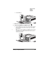
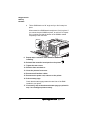
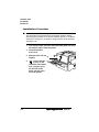
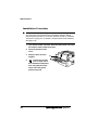
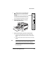
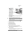
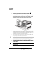
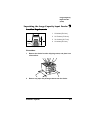
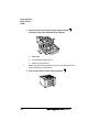
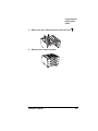
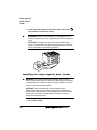
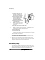
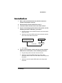
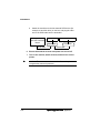
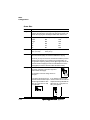
d
Attach the terminator to the last external SCSI device (for
example, a hard disk drive) on the bus, and plug the other
end of the SCSI cable into the terminator.
"!#$
%
!!&
(
!!
)
!
)*!!+ '#
!!
6
Ensure that both the scanner and printer are turned off.
7
Turn on the scanner, wait 5 seconds, and then turn on the
printer.
Caution: The scanner must be turned on first so the printer can
recognize the scanner’s presence.
1
8
Insert the copy key into the “Key” port on the
printer interface panel.
You can’t access the CrownCopy menu unless
the copy key is inserted. The printer can be
either on or off.
Caution: Even though both the copy key and
serial interface have a DB-9 interface, the
connectors are keyed, and they can’t be
interchanged. Make sure that you install the copy
key only in the port marked “Key.”
Your CrownCopy scanner is now ready to use. If
necessary, access the Copier Menu on the printer to
configure the scanner. For complete information on
adjusting copy settings, see “Menu Configuration” on
page 7-9.
Caution: CrownCopy requires a minimum of 64 MB of RAM installed
on the printer.
1
Turn on the scanner, wait 5 seconds, and turn on the printer.
Caution: The scanner must be turned on first so the printer can
recognize the scanner’s presence.
%#
)&
.1
2
Insert the copy key in the “Key” port on the printer’s interface panel.
Caution: Even though both the copy key and serial interface
have a DB-9 interface, the connectors are keyed, and they can’t
be interchanged. Make sure that you install the copy key only in
the port marked “Key.”
3
When the scanner is ready, place a document face down on
the scanner glass.
4
Make sure the printer is on line, and then press the Copy key
on the printer’s control panel.
The control panel message window displays
COPIER MENU
COPY
5
Use the Copier Menu/Copy Mode/Scan Size menu to set the
scan size of the document.
See “Menu Settings” on page 7-11 for details.
6
Press the Select key to display
COPY
READY TO COPY
7
Press the Select key again to begin copying.
8
When the copying is complete, remove the document.
(
#
To print multiple copies of multiple sheets from the scanner’s automatic document feeder (ADF), we recommend that your printer have
a hard disk installed.
)'
.1
»
Note: While you can scan and print multiple copies of single-sheet
documents without a hard disk, a hard disk is required to print
multiple copies of multiple-sheet documents (with or without collation)
from the automatic document feeder (ADF).
The printer’s hard disk is used for temporary storage of the scanned
image. There must be enough free space on the hard disk (at least 15
MB) to store the largest-size scanned image. The size of this image
depends on the paper size and the printer resolution.
This section identifies the amount of Display List memory required to
print multiple copies of multiple sheets (with or without collation) from
the ADF.
1
Enable disk swapping (Administration/Memory/Enable Disk
Swap menu).
2
Increase the Display List memory by 60 MB/60,000 KB
(Administration/Memory/Manual Config/K Mem Display
menu).
The printer automatically reboots when you press the Online key.
3
Choose collation, if necessary.
4
Begin the copying/scanning procedure (Copy key).
5
If the printed output is not correctly collated, use the
Administrator/Memory/Manual Config/K Mem Display menu
to increase the Display List memory in 10 MB (10,000 KB)
increments until the output is correctly printed.
For complete information on this option, refer to chapters 4 and 5
in the Reference manual.
1
Turn on the scanner, wait 5 seconds, and turn on the printer.
Caution: The scanner must be turned on first so the printer can
recognize the scanner’s presence.
%#
))
.1
2
Insert the copy key in the “Key” port on the printer’s interface panel.
Caution: Even though both the copy key and serial interface
have a DB-9 interface, the connectors are keyed, and they can’t
be interchanged. Make sure that you install the copy key only in
the port marked “Key.”
3
When the scanner is ready, make sure that no documents are
on the scanner glass, and then prepare the ADF.
4
Move the paper feed guides on the ADF so that they’re
approximately 0.25"/5 mm wider than the document.
5
Place the document to be copied face down in the input
paper chute, putting the ends of the bottom 2 or 3 sheets
into the automatic feeder.
Slide the stack forward until it rests against the ADF sensor. The
sensor is a small plastic arm inside the ADF. The ADF can be
loaded with up to 50 sheets of A4-, legal-, or letter-size paper.
You might have problems using thick stock in the ADF.
Caution: Do not feed any of the following through the ADF:
Paper with clips or staples
Paper with wet ink
Paper with folds, tears, notches, or curls
Paper with an inconsistent thickness, such as envelopes
Very thin paper
Paper not square or rectangular in shape
Paper smaller than A5 size or larger than A4 width
Tracing, coating, carbonless, or photographic paper
Items other than paper, such as transparencies, metal
sheets, or cloth
Important documents that must not be damaged
)*
$
6
Close the paper guides until they touch the sides of the
paper stack.
Note: Skewing may occur if a gap exists between the guides and
the document.
»
7
Make sure the printer’s Online light is lit.
If the Online light is not on, press the Online key to put the printer
on line.
8
Press the Copy key.
In the printer’s message window you should see
COPIER MENU
COPY
9
Press the Select key, and you should see
COPY
READY TO COPY
10 Press the Select key again and the scanner should begin
copying your document.
Caution: Do not press on or open the scanner cover during the
copy process.
11 When the copying is complete, remove the document.
'
When the printer is on line, press the Copy key on the printer’s control
panel once to enter the Copier Menu.
%#
)+
$
»
Note: The Copy key must be inserted in the “Key” port on the printer
interface panel before you can access the Copier menu.
Copier Menu
Number
of Copies
Select
Mode
Copy
Mode
Origin
Automatic
Color
X Offset
Custom
Color
Y Offset
Custom
Config
Scan
Resolution
Copy
Scan
Size
Horiz.
(in x 100)
Vert.
(in x 100)
Automatic
Gray
)
Scale
Size%
$
5
The quality of your copied image depends on several factors. You
must consider these factors when judging the output quality of your
copied image. The quality of the copy can be adjusted by settings on
the CrownCopy menu. The factors involved in copy quality are
»
The quality of the original
The type of original —text, images, or both
The size of the original
The speed of your copy output
Note: Copies of both color and monochrome originals from the ADF
are subject to a gray background. Use the flatbed for cleaner copies.
'
To access the Copier Menu, press the Copy key once. Then use the
Next or Previous key to scroll across the top-level menus (Copy,
Number of Copies, and Copy Mode). To enter a lower-level menu or
select a menu option, press the Select key. Use the Menu key to back
out of the menu and return to IDLE after you’ve made your selections
or after you’ve completed copying.
»
Note: When you press the Copy key, you gain access to the Copier
menu. To return the printer to normal operation you can exit from this
menu by pressing the Menu key, leaving the copier idle for 60
seconds, pressing the Online key, or going back to do number of
copies. Error messages that normally occur (such as jams) will not
appear on the display until you exit from the Copier menu. Copier
menu changes stay in effect only for the next scan executed.
Caution: Each configuration change you make affects the quality of
your printed output significantly. Therefore, we recommend changing
only one setting at a time, printing a test print, and then determining
if further configuration changes are necessary.
%#
)
$
See chapter 4, “Printer Configuration,” of the Reference manual for
more information on using the configuration menu.
Menu
Copier Menu/Copy
Purpose
Make a copy.
Choices
Copy
When the printer is on line, press the Copy key to access the
Copy menu.
Notes
The default scan resolution is 200 dpi. See “Scan Resolution”
on page 7-15 for information on increasing scan resolution.
'0
Menu
Copier Menu/Number of Copies
Purpose
Set the number of copies you want.
Choices
1 to 999
Each digit is set individually. Use the Select key to move the
cursor to the digit you want to change, and then use the Next
key to increase it or use the Previous key to decrease it. Once
the number you want is set, press the Select key to save it.
)
Default
1
Notes
The number of copies is reset to 1 each time CrownCopy is
used or whenever the Copy menu is exited. When you’re
printing multiple copies, subsequent copies are printed faster
than the first copy.
$
)
Menu
Copier Menu/Copy Mode/Select Mode
Purpose
Specify what type of copy is being made so the printer can
optimize for this type output.
Choices
Automatic Color—Sets color depth to multibit color and scan
resolution to 200 dpi.
Automatic Gray—Sets color depth to 8-bit gray and scan
resolution to 300 dpi.
Custom Color—Allows you to adjust color values.
Default
Automatic Color
Note
You must choose Custom Color in order to change the scan
resolution in the Copier Menu/Copy Mode/Custom Config/
Scan Resolution menu.
Use Automatic Gray when copying documents that are either
black and white or shades of gray; it provides the best quality
output for monochrome images.
+
Menu
Copier Menu/Copy Mode/Origin
Purpose
Specify where the copy is to print on the selected media (in .01"
increments).
Choices
X Offset
0-850
Y Offset
0-1100
X Offset
0
Y Offset
0
Default
Notes
This option assigns the top-left corner of the image, so printing
with defaults places the image at the top leftmost corner of
the page.
%#
)
$
1
Menu
Copier Menu/Copy Mode/Scan Size
Purpose
Select the width (horizontal size) and length (vertical size) of the
image to be scanned to crop (scan only part of) an image or to
reduce the copying time for images smaller than letter or A4.
Choices
Supported Size
Horiz. (in x 100)
Vert. (in x 100)
Letter
Legal
A5
B5
A4
850
850
582
715
827
1100
1400
827
1011
1169
Default
Horiz. (in x 100)
Vert. (in x 100)
850 (8.5")
1100 (11.0")
Notes
These values must be selected if you are using the automatic
document feeder (ADF) as well as the flatbed for copying.
The more you crop out of a scan, the less time it takes to process
and print. For example, if you need to copy a photograph, you
can get faster copies by placing it at the upper-right corner of the
scanner bed and cropping the scan to fit the dimensions of the
photograph (the scanner bed has rulers that mark inches.)
Examples
You can also use the Scan Size menu to crop
an image. Cropping is done from right and
bottom sides of the page.
For example, look at the image shown to
the right:
If you place this image on the
scanner bed and set the Copier
Menu/Copy Mode/Scan Size
Vert. (in x 100) menu to 400,
you’ll get this:
)
If you place this same image
on the scanner bed and set the
Copier Menu/Copy Mode/Scan
Size Horiz. (in x 100) menu to
550, you’ll get this:
$
1 2
Menu
Copier Menu/Copy Mode/Scale Size %
Purpose
Scale the copy.
Choices
50-200
Default
100
Note
To scale a copy, set the scaling percentage and then press the
Copy key. Press the Online key only after the copying has
finished. If you press Online before pressing Copy, the scaling
selection is not saved; your copy prints at the default 100%
scaling.
Moves to the upper-left of the page. The bottom of the page
may be cropped.
. '
Menu
Copier Menu/Copy Mode/Custom Config/Scan Resolution
Purpose
Specify the resolution the scanner should use.
Choices
100, 150, 200, or 300 dpi
Default
200 dpi
Note
In order to change the scan resolution, you must choose the
Custom Color option in the Copier/Copy Mode/Select Mode
menu.
Choose a scan resolution that is at least half of the printer
resolution being used. The higher the scan resolution, the
more detailed the copy output (as long as the printer resolution
being used is double the scan resolution). Also, a higher scan
resolution increases copying time, because of the increased
amount of data that must be scanned and sent to the
printer for processing. (Each time the scan resolution is
doubled, the amount of information that is scanned and
printed is quadrupled.)
%#
)&
,
If this happens...
Do this...
Edges of the copy are
cut off.
Make sure you’re centering documents at the
top of the scanner glass and that the scan size
setting is correct. Also keep in mind that the
size of the scanned print cannot exceed the
printer’s maximum imageable area for the size
paper in use.
Scanner lamp flicker, is The scanner lamp is failing or has failed and
needs to be replaced.
dim, or fails to come on.
Documents don’t feed
smoothly into the ADF.
Clean the ADF.
Several pages feed
into the ADF at the
same time.
Clean the ADF.
Multiple copies of a
Increase the Display List memory client
multipage document in
(Administration/Memory/Manual Config/K Mem
the ADF are incomplete.
Display menu).
Image quality of copies
is not optimal.
Clean the scanner glass: dampen a lint-free
cloth with alcohol or a mild detergent and wipe
the glass clean.
If you’re using an automatic document feeder
(ADF), clean it.
Copies of both color and monochrome originals
from the ADF are subject to a gray background.
Use the flatbed for cleaner copies.
If you’re scanning at 150 dpi, some printed
materials, such as magazines, cause moiré
patterns. To remove these patterns, change
the scan resolution to 200 or 300 dpi (choose
Copier/Copy Mode/Custom Color, and then
Copier/Copy Mode/Custom Config/Scan
Resolution/200 or 300).
)'
!
,
(%%
+ - - “Sources of Support” on page A-2
“QMS World-wide Offices” on page A-5
$
%%
Several sources of help and information are available, depending on
the type of help you need:
657
Your local vendor (the one from whom you bought the printer) may be
best equipped to help you. Your vendor has specially trained service
technicians available to answer questions, and the equipment to analyze your printer problems.
6,
7
Often, “printing” problems have more to do with the application being
used than with the printer. In this case, the application manufacturer is
the best source of help.
53*,8
Q-FAX, a QMS information retrieval service, provides application
notes, technical support notes on common printing problems, and
information about printer specifications, options, accessories, consumables, and prices.
In the United States and Canada, call (800) 633-7213 to reach
Q-FAX. In all other countries, call (334) 633-3850. Have your fax number handy when you call (or place the call from your fax machine's
handset).
You can choose to have either a directory (a list of currently available
documents) or a specific document sent to you. The first time you call,
request the directory (press 2 on your phone or fax keypad when
prompted). Then call back to request specific documents. You can
order up to three documents per call.
$
The QMS server provides access to technical reports, new product
announcements, a trade show schedule, and other general information about QMS.
If you have access to the World Wide Web, you can view the QMS
home page at http://www.qms.com/. The QMS ftp resource is
ftp.qms.com.
"
$
59:
You can contact the QMS Customer Response Center (CRC) in three
different ways:
Telephone—You can call the CRC at (334) 633-4500 (US)
Monday–Friday, 7:00 am–6:00 pm, Central Time.
Note: If you call for assistance, have the following information
ready so our technicians can help you more quickly:
»
Your phone number, fax number, and shipping address
A description of the problem
The printer model and serial number
The type of host computer you’re using
The type and version of operating system you’re using
The interface you’re using, and, if serial, the protocol (for
example, XON/XOFF)
The application and version you’re using
The emulation of the file you’re trying to print (listed on both
the status and startup pages)
Your printer firmware version (listed on the status/startup
pages)
A status page, if you can print one
Fax—You can fax questions to the CRC at (334) 633-3716 (US).
Provide the same information as listed above, and indicate
whether you would like a faxed or a phoned reply.
Internet—If you have access to the World Wide Web, you can
access the CRC through the QMS home page at
http://www.qms.com/
>
%
$$
)</
3)%
(#
General Contact
1 (334) 633-4300
Fax 1 (334) 633-4866
Email [email protected]
Internet http://www.qms.com
Information on QMS products, supplies, and accessories, and on the
authorized QMS remarketer or service provider nearest you
(800) 523-2696
Customer Response Center (CRC)
Technical Assistance
1 (334) 633-4500 7:00 am–6:00 pm Central Time
Fax 1 (334) 633-3716
Internet http://www.qms.com
Latin America Fax
1 (334) 639-3347
National Service
Service Information, Installation, and Maintenance Pricing
1 (800) 762-8894
On-Site Service and Depot Repair Information
1 (800) 858-1597
7:00 am–7:00 pm Central Time
Spare Parts Ordering and Information
1 (334) 633-4300 x2530
8:00 am–5:00 pm Central Time
3)
General Contact
1 (514) 340-0646
Fax 1 (514) 340-0401
Supplies and Accessories
1 (800) 268-0343 x223
National Service
On-Site Service and Depot Repair Information
1 (800) 268-4969
8:30 am–7:00 pm Eastern Time
Spare Parts Ordering and Information
1 (905) 206-9234 x238
8:30 am–5:00 pm Eastern Time
"
&
>
%
$$
3)4
General Contact
(+81)-3 3779-9600
Fax (+81)-3 3779-9650
Internet http://www.qmsj.co.jp
3)!)!#
Anitech
Sydney Business & Tech. Centre
52/2 Railway Parade
2141 Lidcombe NSW
Australia
(+61) 2–9901 3235
Fax (+61) 2–9901 3273
Internet http://www.qmsaus.com.au/
Planetenbaan 60 ‘Corner Plaza’
3606 AK Maarssen
Belgium, NetherThe Netherlands
lands, and all
(+31) 346–551333
unlisted countries
Fax (+31) 346–550170
Internet http://www.qms.nl
Germany and
Austria
'
Vélizy Plus
1 Bis, Rue du Petit Clamart
78142 Vélizy Cedex
France
(+33) 1–410 79 393
Fax (+33) 1–408 30 110
Gustav Heinemann Ring 212
D-81739 Munich
Germany
(+49) 89 63 02 67 0
Fax (+49) 89 63 02 67 67
Via della Repubblica 56
43100 Parma
Italy
(+39) 52–1231 998
Fax (+39) 52–1232 902
>
%
$$
Arenavägen 41, 6th floor
121 77 Johanneshov
Sweden, Finland,
Sweden
Norway, and
(+46) 8–600 01 30
Denmark
Fax (+46) 8–600 01 33
United Kingdom
and Ireland
Saskay House
Unit 24 Sunninghill Business Park
Peltier Road, Sunninghill, Johannesburg
Republic of South Africa
(+27) 11–807 6957
Fax (+27) 11–807 6960
Old Bridge House, The Hythe
Staines, Middlesex TW18 3JF
United Kingdom
(+44) 1784–442255
Fax (+44) 1784–461641
"
)
,
'% - - “Introduction” on page B-2
“Menu Chart Conventions” on page B-2
“Administration Menu” on page B-3
“Installation Menu” on page B-9
“Operator Control Menu” on page B-10
Use this chapter as a quick reference for understanding and
navigating the printer’s configuration menu. The following menu
charts are provided:
»
Administration menu on page B-3
Installation menu on page B-9
Operator Control menu on page B-9
Note: The Copier Menu is displayed in chapter 7, “CrownCopy.”
''"
The following conventions are used in the menu charts:
8
Some menu choices are marked as optional or with a w/item,
indicating that the selection appears in the menu only when the
option is installed.
These charts show only the top-level menus. See chapter 4,
“Printer Configuration,” in the Reference manual for detailed information on menu options.
"
(
Idle
Administration
Installation*
Operator Control
Timeouts
Serial
Parallel
Optional NIC
Resident NIC
ESP Default
PostScript
PCL 5c
HP-GL
LinePrinter
CCITT*
(w/ImageServer)
CGM*
LN03+*
QUIC*
Special Pages
Print Status
Registration Pg
Header Page
Trailer Page
Header Inputbin
Trailer Inputbin
CMM Profile Page
Status Page Type
Startup Options
Do Start Page
Do Sys Start
Do Error Handler
Communications
Emulations
Memory
(see page B-4)
Quick Config
Manual Config
Image Alignment
Default Paper
MP Input Name
Upper Input Name
Opt1 Name
Opt2 Name
Toner
Low Act.
Opt3 Name
Energy
Saver
Top Output
Name
Def.
Resolution
Side Output Name
Maintenance
Def. Resolution
Consumables
Item Replaced
PM Service
Start Period
Miscellaneous
Save Defaults
Restore Defaults
Reboot System
New System Image
Keypad Language
Clock Operations*
Disk Operations
Format Disk
Backup Hard Disk
Restore Disk
Engine
$
Page Recovery
Energy Saver
Toner Low Action
Print Quality
Printer Model
*Optional
8
"
,;
;
&; &
)'
Idle
Administration
Communications
Optional NIC*
CrownNet
Emulation
Mode
Common
Resident NIC
EtherTalk
Min K Spool
LAN Manager
Spooling
HW
Address
Config
Page
Factory
Reset
On
On Input Idle
On Idle
Address
No
Yes
No
Yes
Soft
Reset
No
Yes
Def Job Prio
NetWare
Ring**
Speed
4 Mbps
16 Mbps
PS Protocol
TCP/IP
Source**
Routing
Auto
Single
All
Off
Ethernet
Speed***
Auto
10 Half Duplex
100 Half Duplex
10 Full Duplex
100 Full Duplex
* Optional
** Token-Ring only
*** Fast Ethernet Only
8
"
! )'
Idle
Administration
Communications
Resident NIC
Optional NIC*
CrownNet
Common
EtherTalk
Protocol
Disabled
Enabled
LAN Manager
Network Ident
LaserWriter
QMS RC Res
HP Zoner Res
NetWare
TCP/IP
Connection
Zone Name
Conventional
Spooling
Both
Zone Part 1
Zone Part 2
Default
*Optional
$
8&
"
(#))'
Idle
Administration
Communications
Optional NIC*
Resident NIC
CrownNet
Common
EtherTalk
Protocol
Disabled
Enabled
LAN Manager
NetWare
Printer Name
Default
TCP/IP
Yes
No
*Optional
8'
"
*)'
Idle
Administration
Communications
Optional NIC*
Resident NIC
CrownNet
Common
Protocol
Disabled
Enabled
EtherTalk
Config PServer
File Srv Name 1
File Srv Name 2
File Srv Name 3
Default
PServer Name 1
PServer Name 2
PServer Name 3
Job Check Delay
Conf Check Delay
Burst Mode
PServer Context 1
PServer Context 2
PServer Context 3
LAN Manager
R/N Printer #1- 8
Printer Slot #
PServer Name 1
PServer Name 2
PServer Name 3
Default
NetWare
Printer Name
Printer Name 1
Printer Name 2
Printer Name 3
Default
TCP/IP
Frame Type
802.3 IPX Addr
Ether 2 IPX Addr
802.2 IPX Addr
SNAP IPX Addr
802.5 IPX Addr**
*Optional
**Token-Ring only
$
8)
"
5$)'
Idle
Administration
Communications
Optional NIC*
Resident NIC
CrownNet
Common
Protocol
EtherTalk
Disabled
Enabled
Internet
Address
LAN Manager
Accnting/Rev
Chan
Accnting
Timeout
Subnet
Mask
NetWare
Disabled
Enabled
Community
TCP/IP
SNMP
NMS 1-5
Internet
Address
Access
Port
Assignment
Default
Router
Remove
Passwords
No
Yes
Remove
Hosts
No
Yes
Secure
Files
No
Yes
LPD
Banner
Disabled
Enabled
BOOTP
Disabled
Enabled
RARP
Disabled
Enabled
Read
Write
Trap
Write-Trap
Read-Trap
None
*Optional
8*
Idle
Installation*
Operator Control
Operator Passwrd
(Enter password)
Use Operator Pwd
Off, On
Admin Password
(Enter password)
Use Admin Pwd
Off, On
Administration
*Optional; available only with security key
$
8+
%'
Idle
Operator Control
Copies
001-999
Collation
Off, On
Orientation
Inputbin
Outputbin
Face-up, Upper
Multipurpose Sz
[all supported media sizes]
Color Model
Color Matching
Media
Accounting
Consumables
8
Upper, Multipurpose, Optional1, Optional2, Optional3
Off, On
Color Separation
Installation*
Portrait, Landscape
Chain Inputbins
Oversize Tray
Administration
12x18, 13x18
Off, On
Full Color, Monochrome
ICC Colormatch, ICC RGB Source, ICC Simulation, Link Quality,
Sim in RGB Links
For Upper Bin, For MPT Bin
Mode, Disk Space, Reset Accounting, File Segment
Item Replaced, Print Statistics
*Optional
"
Acrobat
Documentation
Acrobat files 1-3
ADF
Copying 7-6
Administration menu B-3
Adobe
Acrobat 1-3
Antistatic protection 2-2, 3-2, 5-2
AppleTalk
Connection 3-7
See also LocalTalk
Automatic Document Feeder
Cautions 7-8
Automatic document feeder
Scanning 7-6
Backing up
Jaz drive, to 5-11
Zip drive, to 5-11
BuzzBox Lite
Installation 6-14
Kit 6-13
Using 6-15
CCITT 4-6
Common menu B-4
Configuration
CrownCopy 7-9
Configuration menu
Chart B-2
Conventions
See Manual
Copier Menu menu 7-9
Copy option 7-12
Number of Copies option 7-12
Origin option 7-13
Scale Size % option 7-15
Scan Resolution option 7-15
Scan Size option 7-14
Select Mode option 7-13
Copy key 7-6, 7-8, 7-9
Copy menu 7-9
Copy option
See CrownCopy
Copying
ADF 7-6
CrownCopy configuration 7-9
Flatbed 7-5
Scanner 7-5
CrownAdmin
Emulation, downloading optional 4-4
Font, disk, downloading 4-7
CrownCopy
ADF 7-6
Automatic Document Feeder 7-6
Configuration 7-9
Copying 7-5
Installation 7-2, 7-3
Memory 7-6
Menu options 7-12
Requirements, print system 7-2
Setup 7-2
Troubleshooting 7-16
CrownCopy, configuration 7-9
CrownCopy, menu 7-9
CrownNet
LAN Manager menu B-6
TCP/IP menu B-8
Updating print system software 2-11
Updating system software 2-8
CrownNet menu B-4
EtherTalk menu B-5
NetWare menu B-7
Customer Response Center (CRC),
QMS A-4
Customer support, QMS A-2
Device numbers, hard disks 5-3
Disk font
Downloading 4-7
Disk fonts 4-6
Documentation
Overview of this manual 1-2
Download Error Pages 2-12
Downloading optional emulation 4-3
Emulation
CCITT 4-6
Downloading optional 4-3
Optional, downloading 4-3
Using optional 4-6
Error message
Sequential Error 5-14
Ethernet
Updating print system software 2-11
EtherTalk menu B-5
External storage device
Backing up to 5-11
Configuring 5-10
Formatting 5-9
Restoring from 5-13
Turning on 5-8
External storage devices 5-7
Attaching 5-7
Feeder
Large-capacity input
Flatbed
Copying 7-5
Scanning 7-5
Font
Disk 4-6
Downloading from disk 4-7
Intellifonts 4-8
Kanji font internal ID hard disk 4-16
Kanji font SIMM 4-11
PCL 5 font SIMM 4-8
ProCollection 4-6, 4-8
Network 3-3
SCSI 3-7
Internal IDE hard disk 7-2
Configuring 5-11
Kit 5-4
Internet A-3
Hard disk
Backing up 5-11
Configuring 5-10
Device numbers 5-3
External, attaching 5-7
External, formatting 5-9
External, turning on 5-8
Identifying 5-3
Internal IDE, installation 5-4
Restoring 5-13
Jaz drive 5-7
Backing up to 5-11
Restoring from 5-13
Using 5-8
IDE hard disk
Kanji 4-16
Identification
Hard disk 5-3
Storage devices 5-3
ImageServer 4-6
Installation 6-6
BuzzBox Lite 6-14
CrownCopy 7-2, 7-3
Interface kit 3-4
Internal IDE hard disk 5-4
Kanji font internal IDE hard disk 4-18
Kanji font SIMM 4-12
PCL 5 font SIMMs 4-8
SCSI interface kit 3-7
Installation menu B-9
Intellifonts 4-8
Fonts, accessing 4-10
Interface kit 3-3
Installation procedure 3-4
Interfaces
LocalTalk 3-3
7
Kanji
Configuring the printer for 4-18
Fonts, accessing 4-14, 4-18
Hardware requirements 4-12, 4-17
Internal IDE font hard disk 4-16
Software requirements 4-12, 4-17
Kanji font internal IDE hard disk
Installation 4-18
Kit 4-17
Kanji font SIMM 4-11
Fonts, accessing 4-14
Installation 4-12
Key
Copy 7-6, 7-8, 7-9
Security 6-10
Kit
BuzzBox Lite 6-13
CrownCopy 7-2
Internal IDE hard disk 5-4
Kanji font 4-11
Kanji font internal IDE hard disk 4-17
Large-capacity lower input feeder 6-2
Security key 6-10
Time-of-day clock 3-10
LAN Manager Menu B-6
LAN Manager menu B-6
Large-capacity input feeder 6-2, 6-6
Location requirements 6-3
Unpacking 6-3
LCIF
See large-capacity input feeder
LocalTalk 3-7
See also AppleTalk
LocalTalk interface 3-3
Using 3-7
Location requirements
Large-capacity input feeder 6-3
Manual
Acrobat Files 1-3
Contents 1-2
Overview 1-2
Typographic conventions 1-3
Memory
Collation 7-6
CrownCopy 7-6
Memory modules (SIMMs)
Single in-line 2-3
Menu
See Configuration menu
Moving, printer 6-6
NetWare menu B-7
Network interface 3-3
Installation 3-4
Using 3-6
Number of Copies option 7-12
Operator Control menu B-10
Optional emulation
Using 4-6
Origin option 7-13
Password
Setting 6-11
Using 6-12
PC
Updating print system software 2-8,
2-9
PCL 5
Intellifont SIMM 4-8
PCL 5 fonts
Accessing 4-10
Printer options
Kanji 4-11
Printer stand 6-15
ProCollection 4-6
Fonts, accessing 4-10
Protection
Antistatic 2-2, 3-2, 4-2, 5-2
Q-FAX A-2
QFORM 4-19
QMS
Customer Response Center
(CRC) A-4
World-wide offices A-5
Requirements
Location, large-capacity input
feeder 6-3
Resident NIC menu B-4
Restoring data
Jaz drive, from 5-13
Zip drive, from 5-13
Scale Size % option 7-15
Scan Resolution option 7-15
Scan Size option 7-14
Scanner
Copying 7-5
Troubleshooting 7-16
Scanning
ADF 7-6
Flatbed 7-5
SCSI interface 3-7
Installation 3-8
SCSI interface kit
Installation procedure 3-7
Security key 6-10
Password, setting 6-11
Password, using 6-12
Select mode option 7-13
Sequential Error message 5-14
Service
United States A-4
Setup
CrownCopy 7-2
SIMM 2-3
Installation 2-3
Kanji fonts 4-11
PCL 5 font 4-8
Single in-line memory modules
See SIMM
Stand, printer 6-15
Storage
Devices, identifying 5-3
External devices 5-7
Jaz drive 5-7
Zip drive 5-7
Support, QMS
Customer A-2
Internet A-3
Technical A-4
World-wide A-5
System software
Errors, downloading 2-12
Updating via Ethernet 2-11
Updating via PC 2-8, 2-9
Updating, Ethernet connection 2-8
Updating, parallel connection 2-8
Updating, serial connection 2-8
7
TCP/IP menu B-8
Technical support, QMS A-4
Time-of-day clock
Installation 3-10
Troubleshooting
CrownCopy 7-16
Downloading system 2-12
Hard disk, backup 5-14
Scanner 7-16
Typographic conventions
See Manual
Zip drive 5-7
Backing up to 5-11
Restoring from 5-13
Using 5-8
&