1
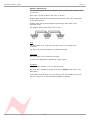
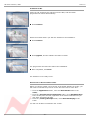
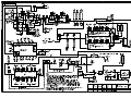
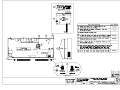
Neve 8801
Channel Strip
User Manual
527 - 358
Issue 7.6
The 8801 is a combined Mic / Line / Instrument Preamp,
with Dynamics processing, EQ and Insert point.
The Audio Router function provides a user configurable signal path,
allowing any order of Dynamics, EQ, and Insert within the channel path.
In addition, the EQ and/or Filters can be placed in the Dynamics sidechain.
88 Series Outboard / 8801
Issue 7.6
Health & Safety Notice
For your own safety and for the protection of others,
please observe the following safety instructions:
•
Read these instructions.
•
Heed all safety warnings.
•
Do not use near water.
•
Clean only with a dry cloth.
•
Do not install near heat sources.
•
Do not block ventilation openings.
•
Protect the power cord.
•
Only use accessories specified by the manufacturer.
•
Unplug when unused for long periods of time.
•
Refer all servicing to qualified personnel only.
NB:
This equipment can only be used with the power supply unit provided with it,
XP Model Number, AEH130PS36
-2-
88 Series Outboard / 8801
Issue 7.6
Customer Service
In the unlikely event that this unit should malfunction or develop a fault,
then please register the fault details on our website, by clicking the link
below.
You will also need to enter the unit's serial number when you do this, so
please have this to hand.
http://www.ams-neve.info/crm/fault_report.html
Once the fault details have been registered, one of our technical support
team will be in touch via email.
This link should also be used for further operational or technical help, or any
general enquiry about the unit.
AMS NEVE
Billington Road
Burnley
Lancs
BB11 5UB
England
Phone +44 (0)1282 457011
Fax: +44 (0)1282 417282
Email: [email protected]
Web: www.ams-neve.com
Support: www.ams-neve.info/crm/fault_report.html
© 2007-2010 AMS Neve Ltd own the copyright of all information and drawings contained in this manual which are not to be
copied or reproduced by any means or disclosed in part or whole to any third party without written permission.
As part of our policy of continual product improvement, we reserve the right to alter specifications without notice but with due
regard to all current legislation.
Disclaimer: The information in this manual has been carefully checked and is believed to be accurate at the time of
publication. However, no responsibility is taken by us for inaccuracies, errors or omissions nor any liability assumed for any
loss or damage resulting either directly or indirectly from use of the information contained within it.
Trademarks: All trademarks are the property of their respective owners and are hereby acknowledged.
-3-
88 Series Outboard / 8801
Issue 7.6
Table of Contents
Health & Safety Notice...............................................2
Audio Routing Screen........................................14
Customer Service...........................................3
Output Section.................................................14
Introduction................................................................5
Bargraph LED Meter..........................................15
Package Contents...............................................5
Overload..........................................................15
System Requirements.........................................5
Rear Panel.................................................................16
Brief Description & Characteristics........................6
Rear Panel Audio Connections.............................16
Line Input....................................................16
Mic Input.....................................................16
DI Input......................................................16
Key input.....................................................16
Front Panel Controls..................................................7
On/Off Switch....................................................7
Input Section.....................................................7
Line Input.....................................................7
Mic Input.......................................................7
PAD..............................................................7
Phantom Power..............................................7
DI Input........................................................7
Digital (Genie) Input.......................................8
Phase Button.................................................8
Dynamics Sidechain Link....................................17
Insert.........................................................17
Line Output..................................................17
Headphone..................................................17
Rear Panel Power section...................................18
Warning symbols..........................................18
USB............................................................18
Technical Earth Switch..................................18
Fuse...........................................................18
Power DIN socket.........................................18
Filters Section....................................................8
High Pass Filter..............................................8
Low Pass Filter...............................................8
Filters to Sidechain.........................................8
Optional Digital board..............................................19
Dynamics Section...............................................8
Dynamics Button............................................8
Analogue to Digital Converter - AES/EBU (AES 3) &
DSD................................................................19
Sampling Frequency Selection........................19
Digital Sync.................................................19
Double Rate AES Output................................20
DSD............................................................20
Headroom...................................................20
75 Ohm WCLK..............................................20
Dynamics Sidechain............................................9
Limiter/Compressor............................................9
Knee.............................................................9
Link..............................................................9
Attack Time.................................................10
Auto Release................................................10
Gain Reduction.............................................10
Older Versions of the 8801......................................21
Expander/Gate.................................................10
Key Input....................................................10
Hysteresis...................................................11
Expander.....................................................11
Invert/Ducker..............................................11
Gain Reduction.............................................11
Firmware Upgrades..................................................22
Selecting a File for Transfer................................22
File Downloading...............................................23
Corrupted or Old Firmware.................................23
EQ Section.......................................................12
EQ Button....................................................12
EQ To Sidechain...........................................12
Low Frequency Band.....................................12
Low Mid Frequency Band...............................12
High Mid Frequency Band..............................12
High Frequency Band....................................12
Recall Software Installation....................................24
Installation for PC.............................................24
Installation for Mac...........................................26
New Versions of Recall Software for Mac..............26
Insert..............................................................13
Other Information.....................................................27
Audio Router....................................................13
Determining the order of current processing.. . .13
Rack Mounting and Cooling............................27
Dimensions..................................................27
Performance Specifications............................27
-----+-----
Appendix: A3 Block Diagrams
8801
Optional ADC board installation
-4-
88 Series Outboard / 8801
Issue 7.6
Introduction
Thank you for choosing the Neve 8801 channel strip.
This unique channel strip is based on the channel strip featured in the world
renowned 88R mixing desk.
It contains the highest quality Mic / Line / Instrument Preamp, Dynamics
processing, EQ and Insert.
The Audio Router function provides a user configurable signal path allowing
any order of Dynamics, EQ, and Insert within the channel path.
In addition, the EQ and or filters can be placed in the Dynamics sidechain.
The configuration of the unit can be stored and recalled via the Neve Recall
software on a PC or Mac.
Up to sixteen 88 series units may be connected to a Recall system
simultaneously in any combination.
Package Contents
Please check that your 8801 package contains each of the following:
• 8801 unit
• External power supply
• Power lead
• User Manual CD
System Requirements
The 8801 may be used as a standalone unit.
If you wish to use the units Recall facility, it should be connected directly to
the computer or via a powered USB hub but not via a passive USB hub.
If you wish to use the Neve Recall software to store and reload user
configurations you must have one of the following supported operating
systems:
PC:
•
•
•
•
Mac:
•
Windows 2000, Service Pack 4 or later
Windows XP, Service Pack 3 or later
Vista, Service Pack 1 or later
Windows 7
Mac OS 10.3.9 or later
-5-
88 Series Outboard / 8801
Issue 7.6
Brief Description & Characteristics
• High quality transformer coupled microphone preamplifier identical to that
used on the 88R console with 0dB to 70dB of gain.
• Switchable Phantom Power.
• 20dB Pad on Microphone and DI inputs.
• Line input with -24dB to +24dB of gain.
• High impedance DI input.
• Phase inversion switch.
• Overload indication at each gain stage.
• High Pass and Low Pass filters switchable between channel path and
Dynamics sidechain.
• Dynamics processing based on 88R circuitry.
• Compression/Limiting with auto release.
• Gate/Expander/Ducker.
• Dynamics Sidechain linkable to other 8801 units.
• Key input.
• Compressor and Gate gain reduction meters.
• Balanced switchable Insert.
• 4 band EQ based on the 88R console, switchable between channel path
and Dynamics sidechain.
• User definable channel path through Dynamics/Insert/EQ using Audio
Router function.
• Line output with +10dB of gain control.
• Headphone output.
• Optional Digital Output Card (AES/EBU/DSD).
• User recall/store current state via Neve Recall software.
• USB link to PC or Mac.
-6-
88 Series Outboard / 8801
Issue 7.6
Front Panel Controls
On/Off Switch
The Neve Logo Switch on the right hand side of the front panel switches the
unit on and off.
The 8801 will always power-up with the same settings as they were when the
power was removed (including the order of processing, Phase, Phantom
Power, but not including any settings on the optional digital card).
Providing no rotary controls have been changed, this ensures that work can
continue straight away from power-up without having to recall any of the
settings.
If you wish the unit to power up in it's default factory state, hold the PAD
button down while switching it on.
Input Section
The input is selected by pressing the I/P GAIN knob.
This selection is shown on the adjacent Line / Mic / DI / Genie leds.
Line Input
The line input is accessible via the rear panel combo connector (¼’’ Jack or
XLR). It accommodates both balanced and unbalanced input signals.
The Gain is variable from -24dB to +24dB using the I/P Gain knob on the
front panel.
Mic Input
The mic input uses the female XLR input of the front panel combo connector
or the female XLR input on the rear panel.
Gain is variable from +20dB to +70dB using the I/P Gain knob.
PAD
The Pad button provides 20dB of gain reduction on the Mic and DI inputs.
It is not available on the Line input.
Phantom Power
The +48V button enables phantom power on the Mic input.
DI Input
The DI input uses the ¼’’ jack input of the front panel combo connector or
the ¼’’ jack input on the rear panel.
The input uses a high impedance instrumentation amplifier (>750k), and
accommodates both balanced and unbalanced inputs.
The Gain is variable from -24dB to +24dB using the I/P Gain knob.
When Pad is switched on the input impedance changes to 100k.
-7-
88 Series Outboard / 8801
Issue 7.6
Digital (Genie) Input
The Digital (Genie) input is available via an optional internal daughter card.
The Genie input is only selectable when this optional card is fitted.
Phase Button
All inputs can be phase reversed using the Phase button.
The Phase button will illuminate to indicate a phase inversion between input
and output.
Filters Section
High Pass Filter
The high pass filter has a 12dB per octave (20dB per decade) slope and a
frequency range from 30Hz to 300Hz.
It is switched into circuit by pressing the High Pass frequency knob.
The associated led will light to indicate it is in circuit.
Low Pass Filter
The low pass filter has a 12dB per octave (20dB per decade) slope and a
frequency range from 1.5kHz to 18kHz.
It is switched into circuit by pressing the Low Pass frequency knob.
The associated led will light to indicate it is in circuit.
Filters to Sidechain
The Filters To Sidechain button puts both filters in the sidechain.
When the filters are in the sidechain they are not available in the channel
path and vice versa.
Dynamics Section
Full Limiter/Compressor and Gate/Expander facilities are available.
The Limiter/Compressor uses the top row of controls and the Expander/Gate
uses the bottom row of controls.
Dynamics Button
The Dynamics button activates the Dynamics section.
When illuminated, both Compressor/Limiter and Expander/Gate functions are
all in circuit.
When not illuminated both are bypassed.
• To disable the Compressor, set the Threshold to +20dBu and the
Ratio to 1.
• To disable the Gate, set the Range to 0dB.
-8-
88 Series Outboard / 8801
Issue 7.6
Dynamics Sidechain
The dynamics sidechain is the control signal for the dynamics processing.
By default the sidechain receives the signal picked up at the input of the
Dynamics gain stage.
The Filters and EQ can be moved to the sidechain path by pushing the Filters
to Sidechain and EQ To Sidechain buttons respectively.
When in the sidechain the Filters and EQ do not act on the channel path.
When Key Input is enabled (by pressing the Gate Threshold knob) the
sidechain receives the signal from the Key Input located on the rear panel on
the D-Type connector.
Limiter/Compressor
The Limiter/Compressor has controls for:
• Up to 30dB of gain make-up
• Pressing the Gain Make Up knob toggles Hard and Soft Knee
• Threshold has a range of -30dBu to +20dBu
• Pressing the Threshold knob selects Link
• Ratio of 1:1 to limiting
• Pressing the Ratio knob toggles between Normal and Fast Attack times
• Release times from 30ms to 3s
• Pressing the Release knob toggles between Release and Auto Release
Knee
The compressor has soft knee characteristics as default with hard knee
available by pressing the Gain Make Up knob.
Link
Link can be selected by pressing on the Threshold knob.
When enabled, the compressor section of the unit can be controlled by the
sidechain of other linked 8801 units.
For example, this allows a stereo input across two modules to be compressed
by the same amount, maintaining the stereo image.
There is no Master/Slave relationship between these signals, the priority is
such that the loudest signal is used as the trigger.
Multiple units can be linked together using the rear panel D-Type connector.
-9-
88 Series Outboard / 8801
Issue 7.6
Attack Time
Pressing on the Ratio knob toggles between Normal and Fast Attack time.
Two jumpers inside the unit (shown in red below) can be placed so the unit
has two variations of attack times.
Default Position
Normal Attack time:
Fast Attack time:
8ms
2ms
Alternative Position
Normal Attack time:
Fast Attack time:
3ms
0.5ms
Auto Release
Pressing on the Release knob switches on Auto Release - a triple timeconstant, programme dependent release time.
Anti pumping and breathing circuitry allows the unit to operate on the source
musically whilst retaining absolute control over the dynamic range.
Gain Reduction
The red meter indicates the gain reduction in dB applied by the compressor.
Expander/Gate
The Expander/Gate has controls for:
• Hysteresis variable from 0dB to 25dB, and pressing the Hysteresis knob
selects Expander mode
• Threshold variable from –30dBu to +20dBu, and pressing Threshold
knob selects Key Input
• Range variable from 0dB to 60dB, and pressing Range knob toggles
between Normal (0.5ms) and Fast (0.05ms) Attack times.
• Release time: 10ms to 3s, and pressing Release knob selects Invert
(Ducker)
Key Input
Key input is selectable by pressing on the Threshold knob (the key input is
on the rear panel combo connector).
When enabled, the sidechain uses the Key Input signal rather than the
signal picked up at the input of the Dynamics gain stage as the control signal
for the Dynamics processing.
- 10 -
88 Series Outboard / 8801
Issue 7.6
Hysteresis
The Hysteresis knob sets the difference in threshold for signals that are
rising or falling in level.
Signals that are rising in level turn on when the level reaches the threshold
level plus the hysteresis value.
Signals that are falling in level turn off at the Threshold level.
Raising the threshold for rising signals prevents noise turning the gate on,
and also allowing a lower threshold for falling signals to prevent reverb signal
tails being prematurely gated.
For example, if the threshold is set at -30 and the hysteresis is set at 10, the
signal level would have to rise above -20dB before the channel turns on, and
the channel would remain on until the signal level fell below -30dB.
Expander
Pressing the Hysteresis knob switches the gate off and the 2:1 ratio
expander on.
The Expander led will light to indicate Expander mode.
Invert/Ducker
Pressing the Release knob inverts the behaviour of the Gate.
This function is sometimes called a “ducker”.
The Invert led lights to indicate that the Gate is in Invert mode.
The function is normally used with an external key input.
When gating, a signal above the threshold level on the key input allows signal
to pass; when ducking a signal above the threshold level on the key input
causes the gain of the channel signal to be reduced by the amount set on the
Range knob.
Gain Reduction
The green meter indicates the gain reduction in dB when the gate is actioned.
- 11 -
88 Series Outboard / 8801
Issue 7.6
EQ Section
EQ Button
The EQ button activates the EQ section.
When illuminated, the EQ is in circuit, when the led is off the EQ is bypassed.
EQ To Sidechain
The EQ To Sidechain button places the EQ in the sidechain.
Placing the EQ in the sidechain removes it from the channel path and vice
versa.
Low Frequency Band
The LF Gain knob sets the cut or boost for the low frequency band with a
range of +/-20dB.
Pressing the LF Gain knob switches the Low Frequency band between
Peaking and Shelving modes.
A led lights to indicate when Shelving is selected.
• The LF Hz knob sets the low frequency between 33Hz and 440Hz.
• When the LF band is set to Peak, pressing the LF Hz knob switches the
band between Low (0.7) and High Q (2.0).
A led lights to indicate the selection of High Q.
• When the LF band is set to Shelving mode, selecting High Q has no
effect.
The High Q led is therefore deactivated and remains unlit.
Low Mid Frequency Band
• The Lo Mid Gain knob sets the cut or boost for the low medium
frequency band with a range of +/-20dB.
• The LMF Hz knob sets the low medium frequency between 120Hz and
2kHz.
• The Lo Mid Q knob adjusts the continuously variable Q between 0.4 and
10.
High Mid Frequency Band
• The Hi Mid Gain knob sets the cut or boost for the high medium
frequency band with a range of +/-20dB.
• The HMF Hz knob sets the high medium frequency between 800Hz and
9kHz.
• The Hi Mid Q knob adjusts the continuously variable Q between 0.4 and
10.
High Frequency Band
• The HF Gain knob sets the cut or boost for the high frequency band with
a range of +/-20dB.
• Pressing the HF Gain knob switches the High Frequency band between
Peaking and Shelving modes.
A led lights to indicate when Shelving is selected.
• The HF Hz knob sets the high frequency between 1.5kHz and 18kHz.
When the HF band is set to Peak, pressing the HF Hz knob switches the
band between Low (0.7) and High Q (2.0).
A led lights to indicate the selection of High Q.
• When the LF band is set to Shelving mode, selecting High Q has no
effect.
The High Q led is therefore deactivated and stays unlit.
- 12 -
88 Series Outboard / 8801
Issue 7.6
Insert
The Insert button switches the insert into the channel path.
The Insert send and return can be found on the rear panel, the send being a
male XLR and the return a female XLR connector.
The 8801 supports both balanced and unbalanced connections.
Audio Router
The Audio Router button allows the order of Dynamics, EQ and Insert to be
set and interrogated within in the channel path.
The default order is DYNAMICS / EQ / INSERT
Determining the order of current processing
To view the current order of the signal path, press the Audio Router
button once.
The Dynamics, Insert and EQ buttons will flash in the order they are
currently set.
If the EQ is in the sidechain, then the EQ To Sidechain button will flash
while the EQ button is illuminated.
Determining the oder of processing is display only, and has no impact on the
channel path.
To set a new channel path order:
Enter programming mode by pressing and holding the Audio Router
button until it begins to flash.
Press Dynamics, EQ and Insert buttons in the order you wish them to be
arranged in.
When the third button has been pressed the Audio Router button stops
flashing, the new order is stored, the channel's path is updated and the unit
the returns to normal operation.
While in programming mode, pressing the Audio Router button will
cancel the programming mode and return to normal operation.
Programming mode will time-out after 15 seconds of inactivity and the unit
will return to normal operation without changing the order of the channel
path.
- 13 -
88 Series Outboard / 8801
Issue 7.6
Audio Routing Screen
When the unit is connected to a computer via USB and the Recall software is
running, if you right-click on the software title-bar at the top of the screen, a
small fly-out menu will give you an option called Audio Routing (Mac users:
CTRL + mouse click).
This enables the various processing items (EQ, DYN, LPF etc.) to be switched in
and out of the audio path by dragging and dropping with the mouse from the
computer, rather than from updating the order from the front of the unit.
As soon as a new item is inserted in the Channel Path or the Dynamics
Sidechain, the unit is updated accordingly.
Similarly, if the order of processing is changed on the 8801, these changes
will be immediately reflected on this screen.
The Channel Path is shown on the first row, with the Side Chain directly
beneath.
All the available (ie bypassed) processing items are shown beneath these two
rows.
Items can be switched in three ways:
To enable an item, drag it from the Available area to the Channel Path
area.
To insert the item into the side-chain, drag it into the Side Chain area.
To disable an item, drag it into the Available area.
On the right of the screen, a panel shows the current order of the processing
items, EQ, Dynamics (Compressor/Gate) and Insert.
To reorder the EQ, DYN, INS units, drag the icons to their desired position
within this panel.
To view another 8801 Audio Routing Screen, use the drop-down menu to
select another unit.
Output Section
The Line output is from a male XLR on the rear panel and accommodates
both balanced and unbalanced connections.
The output signal is routed to a headphone amplifier and is accessible on the
¼” jack socket also on the rear panel.
The signal level for both the XLR line output and the headphone output is
controlled by the O/P Gain knob.
It has a range of between −∞ to +10dB.
The gain of the headphone output can be increased by moving an internal
jumper (J37, as shown in red, left)
This jumper is shown here in the High Gain position across the lowest two
pins.
To swap to the Low Gain setting, put the jumper on the highest two pins.
There is a 6dB difference between the High Gain / Low Gain positions.
- 14 -
88 Series Outboard / 8801
Issue 7.6
Bargraph LED Meter
The VU meter can be set to display the input or output signal level.
Pressing the O/P Gain knob toggles between input and output monitoring
and the current state is indicated by the led to the left of the O/P Gain knob.
The default meter setting is Input.
Overload
There are many gain stages in the 8801 channel strip, and it is possible for
any one of these stages to overload.
Overloading is indicated by one of the following buttons illuminating red:
PHASE
Input stage or input signal overload
DYNAMICS
Dynamics overload
INSERT
Insert overload
EQ
EQ overload (detected at each band of EQ)
DIGITAL OPTION
ADC Option Board overload
If overloading occurs at multiple stages only the highest priority button will
light.
The priority is governed by the signal path of the audio.
The input has the highest priority followed by Dynamics/Insert or EQ in the
order set by the Audio Router.
- 15 -
88 Series Outboard / 8801
Issue 7.6
Rear Panel
Rear Panel Audio Connections
Line Input
The line input combo socket accepts input signals from either male XLR or
male ¼” Jack connectors.
Input signals can be balanced or unbalanced.
Mic Input
The Mic input is on a Female XLR.
This input is in parallel with the XLR input of the Combo connector of the
front panel.
DI Input
The DI input is on a ¼’’ jack input.
This input is in parallel with the Jack input of the Combo connector of the
front panel.
Key input
The key input is located on pins 6, 7 and 8 of the 9 pins D-Type connector.
Input signals can be balanced or unbalanced.
D-Type Pin Outs
1
Dynamics Link Signal
2
Dynamics Link 0v
3
Dynamics Link Signal
4
Dynamics Link 0v
5
- Not connected -
6
Key Input Hi
7
Key Input Lo
8
Key Input 0v
9
- Not connected Case Connected to Unit Chassis
- 16 -
88 Series Outboard / 8801
Issue 7.6
Dynamics Sidechain Link
The dynamics sidechain link is available on the 9 pins D-Type connector pins
1-2 and 3-4.
Pins 1 and 3 as well as pins 2 and 4 are in parallel.
Multiple 8801 units can be linked allowing all linked units to be compressed
by the same amount.
Multiple units can be linked together by forming a daisy chain of the
Dynamics Links.
The diagram below shows how to link 3 units:
Unit 1
Unit 2
Unit 3
Insert
The insert send is on a male XLR and the return is on a female XLR
connector.
The insert can accept a balanced or unbalanced signal.
Line Output
The line output is on a male XLR connector.
It can provide balanced or unbalanced output signals.
Headphone
The headphone output is a on ¼” jack connector.
The level of the headphone output is set by the Output Level knob on the
front panel.
As the 8801 Channel Strip is a mono channel unit, the headphone receives
the same signal on the Left and Right headphone speakers.
- 17 -
88 Series Outboard / 8801
Issue 7.6
Rear Panel Power section
Warning symbols
There are no user serviceable parts inside the unit.
Disconnect the mains lead to isolate this unit.
Please refer to the manual before operating this unit.
USB
The Type B USB socket is used to connect the 8801 unit to a PC or Mac for
Recall store and recall of the unit settings.
The unit should be connected directly to the computer or via a powered USB
hub but not via a passive USB hub.
Technical Earth Switch
!! WARNING !!
Connections to the
technical earth and
changes to the grounding
of the unit should only be
carried out by qualified
personnel
The grounding of the unit can be set to two different points:
1) The Mains earth from the power supply, or
2) The studio technical earth via the CHASSIS screw on the back of the unit.
With the switch in the OFF position the chassis of the unit is connected to the
Mains earth via the power supply.
With the switch in the ON position the chassis of the unit should be
connected to the studio technical earth using the CHASSIS screw on the
back of the unit.
For safety reasons the chassis is NOT disconnected from the main Earth but
is connected through an RC filter.
Fuse
The removable fuse holder houses a 1.6 AT fuse.
Power DIN socket
The 8 pin DIN socket should only be used to connect the power supply
provided with the 8801 unit.
NB:
For technical reasons the orientation of the socket is the opposite way up,
and the “top” of the DIN connector will therefore be underneath.
It is not possible to connect the plug the wrong way up.
- 18 -
88 Series Outboard / 8801
Issue 7.6
Optional Digital board
The 8801 has an expansion slot allowing access for digital connectivity.
The digital option available is an Analogue to Digital converter featuring AES/
EBU and DSD outputs
The 8801 ADC board
must only be installed by
an authorised Neve
dealer. Please contact
your local Neve dealer for
more information.
Please see the Block Diagram at the end of this document for a signal flow
schematic.
Analogue to Digital Converter - AES/EBU (AES 3) & DSD
The optional AES/EBU & DSD digital daughter board provides the following
connections:
• DSD Output
• Wordclock Input and Output
• SPDIF Output
• AES Output
• AES Sync Input
When the Analogue to Digital converter card is fitted the Digital O/P section
on the front panel is enabled.
Sampling Frequency Selection
The sample rate can be selected by pressing the Digital O/P button.
This will toggle through the sampling frequencies one at a time.
The current sampling frequency is indicated by the leds beneath the Digital
O/P button.
Digital Sync
The ADC option board has 2 sync inputs, AES 3 on a female XLR and Word
Clock on a BNC.
If neither sync input is present, the unit will synchronise to its internal clock.
If either of the sync inputs is present at the sampling frequency displayed on
the front panel, the LED (AES or WCLK respectively) will illuminate green
showing that the sync input is being used as a reference.
If the incoming sync sample rate differs from the sample rate displayed on
the front panel, the WCK or AES leds will flash.
If both sync inputs are present and correct the word clock input will be used
as the reference and the AES led will flash.
- 19 -
88 Series Outboard / 8801
Issue 7.6
Double Rate AES Output
It is also possible to select 96kHz (or 88.1kHz) sampling rate with a 48kHz
(or 44.1kHz) sync input.
Similarly it is possible to select 192kHz (or 176.2 kHz) sampling rate with a
96kHz (or 88.1kHz) sync input.
This will cause the unit to output double rate AES on the AES Output
connector.
The sync led will illuminate green indicating the sync reference is still being
used for the digital output even though the ADC is sampling at twice the sync
input sampling rate.
In this situation AES out carries the odd and even samples of the audio
double rate signal on its left and right digital channels respectively.
DSD
Selecting DSD will default to 44.1kHz reference.
If no sync is available it will use its own internal clock.
The DSD output is switchable between SDIF 2 and SDIF 3 with a rear panel
switch.
SDIF2 DSD data requires an external sync clock which is passed to the Digital
to Analogue converter of the receiver.
Preferably use the 8801 Wordclock O/P clock which is available on the back of
the 8801 ADC option.
SDIF3 DSD data have embedded clocks and don't require any external sync
clock.
NB: Please refer to your DSD recording device for compatibility information.
Headroom
The unit can be set to one of three headroom settings; +14dB, +18dB or
+22dB, relative to +4dBu.
The headroom is the number of dBs above +4dBu before the ADC clips.
The Digital O/P button will illuminate red if the selected input level is
exceeded for more than 1 sample.
The headroom can be changed by accessing the switches on the back of the
ADC optional board.
75 Ohm WCLK
Selects a 75Ω input impedance for the WCLK IN.
- 20 -
88 Series Outboard / 8801
Issue 7.6
Older Versions of the 8801
This document contains information on the latest production issue of the
8801 unit.
Some earlier versions of the unit contained the following differences:
1 - The Mic/DI combo connector on the front of earlier units has now been
augmented with separate Mic (XLR) and DI (Jack) connectors on the rear of
the unit as well.
2 - The Key Input signal is now handled by a 9-pin connector, and this
leaves the old Key Input combo connector on the older model, to be re-used
as a Mic Input XLR.
3 - The jack socket (used for the Dynamics Sidechain Linking) and the
combo connector (for receiving the Key Input signal), have now both been
replaced with a single 9-pin connector that handles both of these services on
later models.
The signals for the Dynamics Sidechain Link jack socket on earlier models
were as follows:
Tip
Dynamic Link Signal
Ring
0volts
Sleeve
Both Ring and Sleeve are linked internally
on the 8801, so either a mono or stereo jack
can be used.
In all other ways, the earlier issue of the 8801 is identical in operation,
function and audio integrity as the current production model.
- 21 -
88 Series Outboard / 8801
Issue 7.6
Firmware Upgrades
In order to get the most from your Neve unit, the latest firmware should be
installed.
Upgrading your software is a simple process with on screens prompts to
guide you.
>
>
>
>
Start the Recall software.
On the main screen, right-click the window title bar (Mac users select
Recalls)
Click Upgrade Firmware.
Select the file to transfer.
You will be prompted about removing other units.
When updating units, only the unit that is being updated should be
connected via USB. All other units should have their USB disconnected.
Even if you are updating two units of the same model, they should be
connected individually and updated in two separate operations.
If more than one unit is connected via USB when the Update is about to be
performed, a screen will prompt you to disconnect the other units.
A prompt screen will confirm the software number & version you should
select, and display the current version of firmware for the unit.
Click OK.
Selecting a File for Transfer
The Open File dialog will appear.
To locate the firmware file, browse to the location:
•
•
PC users: C:\Program Files\Neve Recall\Firmware
Mac users: Applications\Neve Recall\Firmware
The file names follow the format down_88XY_V.hex where XY are the last
two digits of the 88 unit name (e.g. '16' for 8816) and V is the software
version number.
A typical filename could be down_8804_3.hex.
Double click on the latest filename which matches your unit.
If an incorrect file is selected the user will be prompted to select another file.
- 22 -
88 Series Outboard / 8801
Issue 7.6
File Downloading
Once the file is selected, the transfer will begin and the Recall screen will
display that the download is under way.
This process may take up to two minutes for each unit.
Upon completion, the message Firmware Update Successful will be
displayed.
Click OK to continue.
You can continue to update other units successfully without restarting Recall,
but the Recall software must be restarted once this process is finished.
If the transfer fails (for example if the USB is removed by accident or power
is lost to the unit), a warning message will prompt to the user to try again.
If Recall is started with a unit that has no firmware, the user will be
prompted to upgrade the firmware, as the unit cannot be used in Recall
unless the firmware installation is successful.
Corrupted or Old Firmware
If the firmware is corrupted or the unit has an old version of firmware, a
prompt will appear upon starting the Recall software to indicate that firmware
must be updated before the user can proceed.
The process described above can then be followed to update the latest
firmware.
- 23 -
88 Series Outboard / 8801
Issue 7.6
Recall Software Installation
Installation for PC
Insert the CD into the drive and the Setup program should automatically
launch.
If the application fails to launch automatically on inserting the CD, then go to
the CD Drive in Windows Explorer and double-click the NeveRecall.msi file
or the setup.exe file to launch the Setup program manually.
Click Next.
Click I Agree, then click Next.
If you click I Do Not Agree, the install procedure will terminate.
The installation programme will select a default location for files to be copied
and created to.
Click Next to keep the default location, or click Browse to select another
location.
Click Next.
Tick as desired then click Next.
- 24 -
88 Series Outboard / 8801
Issue 7.6
Click Install.
The install will start and the progress displayed.
If you wish to launch Recall, tick the Launch Neve Recall box.
Click Finish.
The software will now be ready to use, and will be accessible from Start
Menu / Programs / Neve Recall / Neve Recall, or from the Recall icon
on the Windows Desktop.
- 25 -
88 Series Outboard / 8801
Issue 7.6
Installation for Mac
Insert the CD containing the software into the Mac, and the install
programme will launch automatically.
Click Continue.
Select the location where you wish the software to be installed to.
Click Continue.
Click Upgrade, and the software will start to install.
The progress bar will show the state of the installation.
Once completed, click Close.
The software is now ready to use.
New Versions of Recall Software for Mac
Where you wish to install a new version of the Recall software on a Mac, you
will need to uninstall the previous version first and remove some files:
> From the Applications folder, move the Neve Recall folder to the
Trash;
> From the //System Library/Extensions folder, move Neve8816.kext
to the Trash (move this file, regardless of the actual outboard units you
may have connected via USB)
> From the //Library/Receipts folder, move Neve Recall.pkg to the
Trash.
You will now be able to install the new version.
- 26 -
88 Series Outboard / 8801
Issue 7.6
Other Information
Rack Mounting and Cooling
The rack unit should be installed in a 19 inch cabinet with access to the front
and rear.
No specific air conditioning is required for the rack provided that there is free
flow of air through the rack from front to back and side to side, and that the
ambient air is maintained below 25 degrees centigrade.
Units may be stacked, but at least 1U space should be allowed between each
unit.
Dimensions
Width
48.2 cm / 19 inches
Height
4.4 cm / 1¾ inches (1U)
Depth
24 cm / 9½ inches (without power socket plugged in)
Weight
3 Kg / 6.6lbs
Performance Specifications
Mic input impedance
1.2kΩ
Mic Mic input headroom
+26 dBu (reference 0dBu)
Mic input gain range
0 dB to 70 dB (using pad)
Line input impedance (balanced)
> 20Ω
Line input headroom
+26 dBu (reference 0dBu)
Line input gain range
-24 dB to 24 dB
DI input impedance (balanced)
>750kΩ
DI input headroom
+20 dBu (reference 0 dBu)
DI input gain range
-44 dB to +24 dB (using pad)
Line output impedance
<50Ω
Main output Maximum output
>+26 dBu into 600Ω
Frequency Response
+/- 0.2 dB 10Hz to 20kHz
+/- 0.5 dB 10Hz to 40kHz
THD + N
<0.005%
Line Output to Main Output, 20 Hz to 20 kHz, using a measurement window of 10 Hz to 80 kHz
Line Output to Main Output
<-89 dBu
All audio blocks in circuit
<-80 dBu
All noise measurements made between 20 Hz – 20 kHz using measurement window of 10 Hz – 22 kHz
- 27 -