1
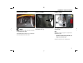
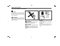
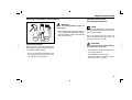
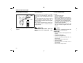
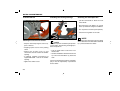
CONTENTS
OVERVIEW AND OPERATION
RIDING INSTRUCTIONS
Identification number, engine number ........................................3
Ride safely ............................................................................... 15
View of vehicle .......................................................................4 - 5
Ride economically and environmentally .................................. 16
Cockpit, handlebar instrument ....................................................6
Running-in instructions ............................................................ 17
Ignition lock and fork-column lock...............................................7
Starting ............................................................................. 18 - 19
Digital clock ................................................................................8
Brakes .............................................................................. 20 - 21
Storage box, luggage hook .........................................................9
Stopping the engine................................................................. 21
Fuel, fuel tank ...........................................................................10
Tank cap ...................................................................................11
SERVICE INSTRUCTIONS
Lubricating oil tank ...................................................................12
Servicing the scooter / cleaning agents ............................ 22 - 23
Side stand, parking stand .........................................................13
Winter operation and corrosion protection............................... 23
Repairing paint damage / servicing the tyres .......................... 24
SAFETY TEST
Lay-up commission .................................................................. 24
Checklist ...................................................................................14
Technical modifications, accessories and spare parts ............ 25
Load and lights .........................................................................15
1
CONTENTS
NOTES ON MAINTENANCE
TECHNICAL DATA
Transmission oil ........................................................................ 26
Engine ......................................................................................45
Checking steering bearing, telescopic fork ............................... 26
Power transmission ..................................................................46
Adjusting the shock absorber ................................................... 27
Chassis .....................................................................................46
Tyres ......................................................................................... 28
Lubricants and operating fluids ................................................47
Front wheel brake .............................................................. 28 - 30
Electrical equipment .................................................................47
Rear wheel brake ..................................................................... 31
Dimensions and weights...........................................................48
Adjusting the play of the twist grip throttle control .................... 32
Cleaning the air filter.......................................................... 33 - 35
Checking the spark plug ........................................................... 36
Fuse.......................................................................................... 37
Battery ................................................................................ 38 -39
Changing the light bulbs .................................................... 41 - 43
Adjusting the headlight ............................................................. 44
2
WARRANTY AND SERVICE DATA
Warranty conditions ..................................................................49
List of wear items...............................................................50 - 51
Inspection plan ..................................................................52 - 54
Proof of maintenance ........................................................55 - 56
SUMMARY AND OPERATION
Identification number
Chassis number
Engine number
2
1
NOTE
The description for right- and left-hand side
is viewed from the driver.
The identification number (1) is located on
the frame below the front cover.
3
The chassis number is located on the frame
behind the cover (2).
The engine number (3) is located on the
left-hand side.
Key
With the scooter you get two separate indefinite keys for:
-
Ignition lock, lubricating oil tank, storage box and tank cap.
Keep the spare key at a safety place.
3
OVERVIEW AND OPERATION
Right-hand side view
1 Storage box with tool kit
6
2 Luggage hook
3 Cover for lubricating oil tank
4 Battery box and fuse
1
2
5 Ignition- and fork-column lock
7
6 Brake fluid container for
front wheel brake
5
7 Handbrake lever for front brake
8 Spark plug
3
8
4
4
OVERVIEW AND OPERATION
Left-hand side view
9
Handbrake lever for rear brake
10
10 Cockpit
11 Tank cap
12 Transmission oil filler screw
13 Kick starter
9
11
14 Parking stand
15 Air filter
16 Side stand
12
16 15
14 13
5
OVERVIEW AND OPERATION
Cockpit
Handlebar instrument, left
1 2
5
6
7
Handlebar instrument, right
2
6
5
8
3
9
1
4
3
4
Instruments
1 Fixed grip
6
1 Speedometer
km/h / mph
2 Handbrake lever for rear brake
7 Throttle
2 Odometer
km
3 Direction-indicator switch
4 Digital clock
Instrument lights
green
6 Oil level - two stroke oil
indicator
red
6
Off
Position light
Position light and driving light
low beam
Push button for switch off
5 Lown beam indicator
green
9
4
Handbrake lever for front brake
8 Light switch
Switch to the left:
Left indicator on
Switch to the right:
Right indicator on
3 Fuel indicator
7 Left and right direction
indicator
7
Starter button
Push-button: horn
5 Emergency off switch
The engine does not start
The engine starts
CAUTION
The EMERGENCY OFF switch (5) is a
safety device and should normally be
.
in position
OVERVIEW AND OPERATION
Ignition- and fork-column lock
Key positions
2
NOTE
1
3
Activate the parking light only for a limited
period. Take into account the charge of the
battery.
and
The key can be removed in positions
.
(1) Operating position
Ignition and all circuits activated.
WARNING
While riding, do not switch the ignition
!
off
NOTE
Keys
With the scooter you get two indefinite ignition keys. Keep the spare key at a safety
place.
(2) Ignition off
Fork column not locked (handlebars
can be freely turned to the left or
right).
(3) Fork column locked and Ignition off
Turn the handlebar to the left as far
as to the stop.
Push and turn the key to the left unposition.
til it is in the LOCK
The fork column is now locked.
7
OVERVIEW AND OPERATION
Digital clock
Mode and Set
Button M press 1 time
Changing between date and
time
Button M press 2 time
until the month appears
The month value can be set by
pressing button S
M
S
NOTE
The Cockpit is supplied by the vehicle battery. The display is only visible when the
ignition is on.
After disconnecting and reconnecting the
battery the clock time needs to be reset.
M
Mode for:
date or time
S
Set for:
date and time
8
Button M press 3 time
until the day appears
The day value can be set by
pressing button S
Button M press 4 time
until the hours appears
The hours value can be set by
pressing button S
Button M press 5 time
until the minutes appears
The minutes value can be set
by pressing button S
Button M press 6 time
End of mode. Date and time is
set and ( : ) flashes.
Button S press 1 time
The date value appears for a
moment
Button S press 2 time
The seconds are shown.
Press the button S again to
return to the time value.
OVERVIEW AND OPERATION
Storage box
Luggage hook
- Do not store valuables in the box.
- Make sure that the seat has been locked
completely after is was pressed down.
- Take out valuables before washing to
avoid wetting these objects.
1
1
- Do not place thermal sensitive objects
in the box because of engine's heat and
high temperature.
Unlock
- Insert the ignition key (1) into the lock
turn and press down the key to the right
or left direction (OPEN).
Use the hook (1) only for small baggage
pieces.
Lock
- Press down the seat (2) until the lock is
engaged.
Maximum load capacity: 1.5 kg
Do not transport bulky loads.
WARNING
- Pull out the ignition key.
Never leave the key in the storage box.
WARNING
After the seat is closed check if its locked
firmly! -Risk of accidents!
Maximum load capacity: 10 kg
9
OVERVIEW AND OPERATION
Fuel, fuel tank
Fuel stock, tanking
WARNING
Fuel is highly inflammable and can explode. Do not smoke or bring a naked
flame near the fuel tank.
Fuel expands under the influence of heat
and the sun. Therefore, never fill the tank
to the brim. Never fill the tank while the
engine is running.
1
Never bring a glowing cigarette or naked
flame near an open tank, because fuel
vapour could suddenly ignite.
NOTE
The fuel indicator (1) is active when the
ignition is turned on.
The scale with the tank symbol
bers for a tank stop.
0
=
100 =
remem-
Empty
Full
Dont run down the fuel tank until it is
empty.
Filling up with fuel
- Use only premium lead-free fuel (min. 95
octane)
10
OVERVIEW AND OPERATION
Tank cap
1
2
4
5
3
NOTE
The tank cap (1) is located behind the
seat.
Unlock:
- Turn the cover (2) to the left or right
side.
- Insert the ignition key in the lock (3) turn
to the left and open the tank cap (4).
Lock:
- The marks (5) must be in front before
closing the tank cap.
- Close the tank cap by turing with the ignition key to the right and pull out the key.
- Close the cover (2).
11
OVERVIEW AND OPERATION
Lubricating oil tank
3
1
2
4
1
CAUTION
Check the oil level during every tanking
and replenish if necessary.
If the oil level is too low, the indicator (1
) will light up. Replenish two stroke
oil within the next 50 km.
Damage caused by not observing this
instruction will not be covered under
warranty.
12
Filling up with lubricating oil
- Use only mineral - or semi-synthetic oil
for separate injection:
API-Norm TC, JASO-Norm FC.
- Insert the ignition key in the lock (1) turn
to the left and open the inspection cover
(2).
- Open the oil cap (3) and replenish max.
to the mark (4) of the oil filler.
- Tighten the oil filler cap by hand.
- Lock the inspection cover (2) with in ignition key.
OVERVIEW AND OPERATION
Side stand and parking stand
3
1
2
Propping up the scooter on the side
stand.
WARNING
Always make sure that the stand is
resting on firm ground. On sloping
roads, always park the scooter facing
uphill.
It is essential that the side stand is
folded up before starting off! -Risk of
accidents !
Side stand
NOTE
The scooter is equipped with a side stand
switch. If the side stand is folded up the
engine is shoot off and will not start.
- Switch off the engine.
- Put your left hand on the left-hand
handlebar grip.
- Hold with your right hand the holder grip
(3).
- Fold out the arm of the side stand (1) as
far forward as it will go and stop by foot.
- Slowly tilt the scooter to the left until its
weight is supported.
Parking stand
- Switch off the engine.
- Put your left hand on the left-hand
handlebar grip.
- Hold with your right hand the holder grip
(3).
- Push the parking stand (2) down until the
two skids are on the ground.
- Put you full body weight on the operating
mandrel of the main standard.
- Pull the scooter towards the rear and
simultaneously upwards onto the parking
stand.
- Check that the scooter is standing
firmly.
13
SAFETY TEST
Checklist
Before each ride, carry out a safety
check using the checklist.
Take the safety check seriously. Carry out
maintenance activities before you start your
ride or ask a specialized Sachs dealer to do
so. This will provide you with the cer tainty
that your motorcycle corresponds to traffic
regulations. A technically faultless motorcycle is a basic requirement for the safety
of both yourself and other road users.
Before starting your ride, check the following:
– Steering (smooth and free of play)
– Clutch lever play
– Lubricating oil quantity
– Fuel quantity
– Front brake
– Rear brake
– Tyres (profile and pressure)
– Telescopic fork
– Load / lights
– Total weight
– Lights
– Brake fluid (level)
– Brakes (operation)
In case of problems or difficulties, contact a
Sachs dealer, who will do everything possible to assist you.
14
WARNING
While the engine is running or the ignition is on, do not touch the ignition
system.
FIRE HAZARD
The exhaust system becomes very hot.
While riding, idling or parking, make sure
that no inflammable materials (e.g. hay,
leaves, grass, coverings or luggage, etc.)
can come into contact with it!
SAFETY TEST
Load / lights
WARNING
For the sake of your safety, use only
original Sachs accessories or products
released by Sachs.
Sachs cannot judge for each third-part
product whether it can be safely used in
combination with your Sachs motorcycle.
Nor can a official approval give such a guarantee in all cases, since the test scope is
not always sufficient.
Ride safely
Correctly loaded
- Make sure that the left-right weight distribution is balanced.
- Check that fastenings are correct and
tight.
- Do not transport bulky loads.
- Do not cover the lights.
WARNING
The total allowable weight may not be
exceeded.
Check the tyre pressure.
NOTE
Sachs accessories and Sachs-approved
products as well as qualified advice are
available from all specialized Sachs dealers.
Checking the lights
WARNING
Before any ride, check the operation of
all lighting components.
- Check that the headlamps and lenses are
clean.
CAUTION
Riding safety is largely also determined
by the manner of riding.
Therefore:
– Put on a tested/approved safety helmet
and correct close the buckle.
– Wear suitable protective clothes.
– Rest your feet on the footrests.
– Do not ride if your riding ability has been
compromised.
Your reactions can be adversely affected
not only by alcohol, but also by drugs and
medicines.
– Strictly observe all traffic regulations.
– Always adapt your riding speed to the
traffic and road conditions.
On smooth, slippery roads take into account
that your riding stability and braking power
are limited by the grip of the tyres on the
road top.
15
RIDING INSTRUCTIONS
Ride economically and be aware of the environment
Fuel consumption, environmental pollution
and wear of engine, brakes and tyres depend on various factors.
Your personal riding style is highly determinant for economical fuel consumption
and exhaust gas and noise generation.
While idling, the engine takes a long time
to warm up to operational temperature. In
the warm-up phase, however, the wear level
and pollutant emissions are very high. It is
therefore best to start riding immediately
after start-up.
Turn the engine off when waiting in traffic.
Different riding conditions affect fuel consumption. The following conditions are unfavourable for fuel consumption:
- High traffic density, especially in big cities
with many stops for traffic lights.
- Frequent short rides with repeated starts
and warm-ups of the engine.
- Riding in a column of motor cycles at low
speed, meaning riding with relatively high
revs.
Avoid rapid acceleration
Open the throttle not further than needed,
in order to reduce fuel consumption as well
as pollution and wear levels.
Do not use excessive revs; change up as
soon as possible and do not change down
until it is necessary to do so.
Plan rides ahead of time in order to avoid
heavy traffic.
Ride as evenly as possible and look
ahead as far as possible.
Unnecessary acceleration and hard braking
cause high fuel consumption and increased
pollution levels.
16
Fuel consumption is also affected by conditions that are out of your control, for instance, poor road condition, hills, riding in
winter.
Observe the following aspects for economical fuel consumption:
- The planned inspection intervals must be
closely observed.
- Regular service by a specialized Sachs
dealer will guarantee not only continued
operability, but also economical fuel consumption, low environmental pollution
and a long lifespan.
- Check the tyre pressure every two
weeks.
Low tyre pressure increases rolling resistance. This increases fuel consumption
and tyre wear and adversely affects riding
behaviour.
- Continually check fuel consumption.
- Frequently check the lubricating oil.
RIDING INSTRUCTIONS
Running-in
Running-in instructions for engine
and transmission
CAUTION
Excessive revs while running-in the engine increases the wear of the engine.
Engine faults during the running-in period must be immediately reported to a
specialized Sachs dealer.
NOTE
During the running-in period, ride in frequently changing load and rpm ranges. Select winding and slightly hilly routes. Avoid
constantly low rpm counts and full throttle
under load.
- During the first 500 km:
Less than 1/2 throttle.
Running-in new tyres
- Up to 1.000 km:
Less than 3/4 throttle.
New tyres have a smooth surface. They
must therefore be roughened by carefully running them in at various slanted
positions.
Only then will the surface obtain its full
grip!
CAUTION
CAUTION
The first inspection must be carried out
immediately after the first 1.000 km.
You can save yourself delays by making
an appointment with a specialized Sachs
dealer in advance.
Running-in new brake linings
WARNING
New brake linings must be run-in and
will not have their full friction power until
after 500 km.
The slightly reduced braking effect can
be compensated for by an increase in
the pressure on the brake lever.
During this period, avoid unnecessary
hard braking actions!
17
RIDING INSTRUCTIONS
Starting with the electric starter
2
WARNING
Propping up the scooter with the parking
stand. Operate the rear handbrake lever
to avoid a moving of the scooter.
Avoid high engine rpm's while the
vehicle is standing still, otherwise the
clutch will engage.
NOTE
The scooter is equipped with a side stand
switch. If the side stand is folded up the
engine is shoot off and will not start.
5
3
1
Before starting
- Propping up the scooter with the parking
stand.
- Turn the ignition lock (1) with the ignition
key to its operating position
.
- Do not open the throttle (4).
- Pull and hold the handbrake lever (2).
- Operate the start button
CAUTION
If the engine won’t start immediately,
release the start button, wait a few seconds and push it again. Each time, push
the start button for just a few seconds in
order to save the battery. Never push the
start button for more than 10 seconds.
(5).
- If the engine can not be started after the
starter motor is running for 3-5 seconds,
open the throttle (4) 1/8 - 1/4 turns and
start again.
- Push the scooter off its parking stand.
- Mount the scooter.
- Release the brake before riding.
18
4
WARNING
Never allow the engine to run in an enclosed space. Exhaust gases are highly
toxic and can kill.
RIDING INSTRUCTIONS
Starting with kick starter
- Propping up the scooter when operating
the kick starter.
- Turn the ignition lock (1) with the key to
its operating position
.
- Do not open the throttle (4).
6
- Depress the kick starter lever (6) quickly
and the engine will start.
- After the engine is running return the kick
starter lever to its normal position.
CAUTION
The EMERGENCY OFF switch (3) is a
safety device and should normally be
in position
.
ON:
Switch downwards. The engine will start
when the kick starter lever is used.
OFF:
Switch upwards. The engine will not start.
NOTE
CAUTION
After starting the engine, check that the
kick starter lever (6) is returned to its
normal position.
Use the kick starter from time to time to
maintain its function.
19
RIDING INSTRUCTIONS
Braking
Wet brakes
Washing the motorcycle or riding through
water or rain can delay the braking effect
due to wet or (in winter) ice-covered brake
discs and linings.
WARNING
The brakes must first be operated until
they are dry
Salt film on the brakes
When riding on salted streets without braking for a while, the full braking effect may
be delayed.
Oil and grease
WARNING
The brake discs and linings must be free
of oil and grease!
If the motorcycle is not used for a while,
a rust film may form on the brakes and
thus increase the braking effect. A thick
rust film can cause the brakes to lock
up. When setting out on a ride after a
long lay-up period, carefully operate the
brakes several times until they work normally.
NOTE
Make sure you practice braking for emergency situations, but do so where you will
not pose a risk to yourself or others (e.g. a
deserted parking area).
20
WARNING
Operate the brakes to grind off the salt
deposited on the brake discs.
Dirty brakes
When riding on dirty streets, the braking
effect can be delayed due to dirty brake
discs and linings.
WARNING
Operate the brakes until they are
clean. Lining wear is increased by dirty
brakes!
RIDING INSTRUCTIONS
Braking
Stopping the engine
1
2
3
Braking
The front brake and rear brake are operated
independently from each other.
The front brake is operated via the righthand brake lever (1) on the handlebars, and
the rear brake is operated via the left-hand
brake lever (2).
When stopping or slowing down, release
the throttle gas and operate both brakes
at the same time.
On tight curves, sandy / dirty streets, wet
asphalt and icy roads, use the front brake
carefully: if the front wheel locks, the bike
will slide sideways.
Brake with care. Locked wheels do not have
much braking effect and can lead to skidding / crashing. In principle, do not brake
on a curve, but before the curve.
Braking on a curve increases the danger
of sliding.
- Turn the ignition lock (3) with the ignition key
.
to the position
- Pull out the ignition key.
21
SERVICE INSTRUCTIONS
Servicing the motorbike / cleaning agents
NOTE
Regular, expert service will help maintain
the value of your motorcycle and is a condition for guarantee claims for corrosion and
other such damage.
CAUTION
Rubber and plastic parts will be damaged by caustic or penetrating cleaning
agents or solvents.
WARNING
Always carry out a brake test after cleaning and before starting a ride!
CAUTION
Do not use steam or high-pressure jet
devices!
Such devices can damage seals, the hydraulic braking system and the electrical
system.
22
CLEANING
- To wash the motorcycle, use a soft sponge
and clean water.
- Afterwards, dry off with a polishing cloth
or chamois.
- Do not wipe off dust or dirt with a dry
cloth, to avoid scratching the paint or covering.
SERVICE INSTRUCTIONS
Servicing the motorbike / cleaning agents
Operation in winter and
anti-corrosion protection
CAUTION
Never use paint-polishing agents on
plastic parts.
- After a longish ride, thoroughly clean the
chassis and the aluminium parts and preserve them with a commercially available
anti-corrosion agent.
PRESERVATION AGENTS
When necessary, the motorcycle must be
preserved with commercially available preserving and cleaning agents.
- By way of precaution (especially in winter), regularly treat parts liable to corrosion with preservation agents.
NOTE
Protect the environment by using only environmentally friendly preservation agents,
and use them frugally.
Use of the motorcycle in the winter can
cause considerable damage due to the
presence of salt on the roads.
CAUTION
Do not use hot water, which would increase the effect of the salt.
- At the end of each ride, wash the motorcycle with cold water.
- Thoroughly dry the motorcycle.
- Treat parts liable to corrosion with waxborne anti-corrosion agents.
23
SERVICE INSTRUCTIONS
Repairing paint damage
Minor paint damage should be immediately
repaired.
24
Servicing tyres
Lay-up / commission
If the motorcycle is not used for a longer
period, it is recommended to support the
motorcycle so that its weight is not on the
tyres.
You can prevent the tyres from becoming
dry and brittle by spraying them with a
silicone-rubber treatment. First thoroughly
clean the tyres.
Do not store the motorcycle or the tyres
in hot spaces (such as a boiler room) for
longer periods.
Lay-up
- Clean the motorcycle.
- Remove the battery.
Observe the maintenance instructions.
- Spray suitable lubricants onto the brakelever and clutch-lever joints and the sidestandard and main-standard bearings.
- Rub bright / chromium-plated parts with
acid-free grease (Vaseline).
- Store the motorcycle in a dry room and
jack it up so that its weight is not on the
wheels.
WARNING
A minimum tyre-profile depth of
2.0 mm must be maintained at all
times.
NOTE
Combine lay-up / commission activities with
an inspection by a Sachs dealer.
Commission
- Remove the preservation agents from the
outside.
- Clean the motorcycle.
- Install the charged battery.
- Preserve the battery terminals with terminal grease.
- Check / adjust the tyre pressure.
- Check the brakes.
- Carry out activities according to the inspection plan.
- Carry out the safety checks.
SERVICE INSTRUCTIONS
Technical changes, accessories and spare parts
WARNING
CAUTION
Technical changes to the motorcycle can
lead to cancellation of the EC operating
license.
We recommend using only approved
Sachs accessories and original Sachs
spare parts for Sachs motorcycles.
Should you want to make technical changes, observe our guidelines. This will serve
to prevent the motorcycle from being damaged and the traffic and operational safety
being retained. A specialised Sachs dealer
can carry out these activities with meticulous care.
This is in your own interests: the safety,
suitability and reliability of these accessories and parts will have been tested
specifically for Sachs motorcycles.
Always consult a Sachs dealer before buying accessories or making any technical
changes.
For approved Sachs accessories and original Sachs spare parts, see a specialised
Sachs dealer.
He will also ensure that they are professionally installed.
Although we keep track of the market, we
cannot evaluate nor be held liable for the
quality of non-approved accessories and
parts, even if they have a certificate of
acceptance from an officially recognised
technical testing/supervision agency, or
a license issued by the authorities.
25
NOTES ON MAINTENANCE
Transmission oil
Checking the steering bearings
Checking the telescopic fork
- Pull the hand brake to block the front
wheel brake.
1
1
- Now pump the fork girders (2) several
times up and down using the handlebar.
- The suspension should respond perfectly.
- Check the fork girders for oil leaks.
2
NOTE
Checking the transmission oil level
NOTE
- Stop the warmed-up engine, wait for approx. 5 minutes.
- Propping up the scooter on the parking
stand.
- Remove the oil filler screw (1) and
check if the oil level is below the oil-filler
opening.
- If required, replenish transmission oil
Hypoid SAE 85W - 140 via the oil-filler
opening.
- Tighten the oil filler screw.
26
The telescopic fork should not jam up when
turned and it should swing back lightly to
both end positions.
- Pull the hand brake to block the front
wheel brake.
- Hold the handlebar with both hands and
try to move the handle bar (1) back and
forth.
If the fork column bearing shows noticeable
play, it must be adjusted by a specialised
Sachs dealer.
If damage to the telescopic fork or the spring
strut is found have the motorbike examined
by a professional Sachs dealer.
NOTES ON MAINTENANCE
Adjusting the shock absorber
Adjusting the spring preload
NOTE
1
A
B
WARNING
The spring preload can be infinitely adjusted.
Turn the adjustment nut (1) with a suitable spanner in direction „A“ to increase the
spring preload (harder suspension).
Turn the adjustment nut (1) with a suitable
spanner in direction „B“ to reduce the spring
preload (harder suspension).
Before taking a ride adjust the spring
preload of the spring strut according to
the total weight!
A = harder
B = softer
27
NOTES ON MAINTENANCE
Tyre profile
1
3
2
While the tyres are cold:
Twist off the valve caps.
Check/adjust the tyre pressure.
Twist on the valve caps.
Tyre pressure
Front
2.0 bar
Rear
2.25 bar
Tyre size
The standard scooter is provided with the
following tyre sizes:
Checking the tyre profiles
WARNING
Observe the minimum profile depth prescribed by law.
Never ride without valve caps (1). Firmly
tightened valve caps prevent the tyre
from suddenly losing pressure.
- Measure the profile depth at the centre
(2) of the tyre’s tread.
28
Recommended minimum profile depth:
2.0 mm
Observe the wear marks (3).
Front
Rear
Checking the tyre pressure
All Tyres are tubeless.
120/70-12 56J
130/70-12 56J
WARNING
Adjust the tyre pressure according to
the total weight load. Never exceed the
rated total weight or the bearing capacity
of the tyres.
Incorrect tyre pressure will have a considerable effect on the riding properties
of the scooter and the lifespan of the
tyres.
WARNING
Use only tyres approved by the manufacturer. The use of non-approved tyre
brands, types or sizes leads to the operating permit of the vehicle becoming
null and void. Use only pairs of tyres
produced by the same manufacturer.
NOTES ON MAINTENANCE
Front wheel brake
Front brake-fluid tank
- Turn the handlebars until the brake-fluid
tank (2) is level.
2
1
- The brake fluid level (3) should be
between the minimum (MIN) and the
maximum marking (MAX).
MIN
3
- If air bubbles can be seen, check the
brake linings for wear; if necessary,
replenish the brake fluid by a SACHS
dealer.
Check the brake-fluid level
WARNING
Sudden changes in play or a spongy feel
of the brake lever (1) can be caused by
faults in the hydraulic system.
Do not ride on when in doubt about the
operability of the brake system. Immediately consult a Sachs dealer.
WARNING
Every two years, the brake fluid must
be changed by a Sachs dealer. The level
must not drop below the MIN mark. Use
only brake fluid of the DOT 4 classification.
CAUTION
Do not spill any brake fluid on painted
or plastic surfaces as it will demage the
surface severely.
29
NOTES ON MAINTENANCE
Front wheel brake
!
3
B
!
Checking the brake linings
- Remove the protective cap (1) at the
brake calliper.
CAUTION
The minimum lining thickness must be
maintained.
NOTE
For your own safety, we recommend having
activities to the brake system carried out by
a Sachs dealer.
- Visually inspect the disc brake (3).
- Visually inspect the sight glass (2) at the
brake calliper.
- Check the thickness of the disc brake.
- Check the thickness of the brake lining.
Minimum thickness: B = 3.0 mm
Minimum thickness: A = 2.0 mm
- If the disc thickness is below the minimum, have the disc brake (3) replaced
by a Sachs dealer.
- If the lining thickness is below the minimum, have the brake lining (2) replaced
by a Sachs dealer.
30
Checking the disc brake
NOTES ON MAINTENANCE
Rear wheel brake
1
3
A
2
Adjusting the rear wheel brake
CAUTION
For your own safety, we recommend having activities to the brake system carried
out by a Sachs dealer.
NOTE
After a longer period of operation, adjustment
of the brakes is essential due to natural
wear of the brake-shoe linings.
Checking
- An external sign of the brakes needing
adjustment is the constantly increasing
free travel (A) of the handbrake lever (1)
10-20 mm.
Adjusting
- Screw the nut (2) on the rear-wheel brake
onto the brake rod until the handbrake
lever reach a free travel of 10-20 mm.
- After this measurement is attained, the
brake shoes should be heard brushing
against the brake drum.
CAUTION
4
Checking the brake linings
CAUTION
The thickness of the brake lining may
not be lower than the minimum value.
Operate the handbrake lever (1) and visually inspect it.
Check the thickness of the lining:
The extension of the wear indicator
(3) at the brake lever must be in front
of the minimum mark of the scale (4)
when the rear brake is depressed.
If the thickness of the lining has fallen
below the minimum, have a specialised
Sachs dealer replace it.
H av e a S a ch s d e a l e r ch e ck t h e
adjustment.
31
NOTES ON MAINTENANCE
Adjusting the play of the twist grip throttle control
4
2
A
3
1
Check:
- Check the throttle cable for light movement by turning the twist grip (1) from
closed to open position.
- Move the handlebar to check whether the
throttle cable moves freely.
Adjustment:
- Push back the protective cap (2).
- Slacken the lock nut (3) on the handlebar.
- Turn the setscrew (4) accordingly.
- Check whether the throttle cable is
obstructed by other parts.
- Tighten the lock nut (3).
- Open the twist grip throttle control until
resistance can be felt.
- Push over the protective cap (2).
- Measure the play.
Nominal value: A = 1-2 mm
32
- Check the play.
NOTE
If the play cannot be corrected this way,
have the scooter checked by your Sachs
dealer.
NOTES ON MAINTENANCE
Cleaning the air filter
1
4
2
6
5
2
3
NOTE
The scooter is attached with a oil foam air
filter. In case of heavy dirtiness the foam
(11) has to be replaced.
.
-
Remove the screws (2) and take off the
storage box (3) together with the seat.
-
Disconnect the hose (4) from the air
filter housing.
-
Remove the clamp (5) from the carburettor and disconnect the manifold (6).
Disassembly and cleaning
- Open the seat (1).
33
NOTES ON MAINTENANCE
Cleaning the air filter
11
9
9
7
9
9
8
-
Remove the screws (7) and take off the
air filter housing (8).
10
9
9
Disassembly and cleaning
- Remove the screws (9) and take off the
air filter cover (10).
-
Remove the foam (11).
-
Clean the foam with Motorrex air
cleaner.
-
Afterward soak and wring out the foam
with air filter oil.
Clean
Squeeze
Drench in air filter oil
34
Squeeze
NOTES ON MAINTENANCE
Cleaning the air filter
CAUTION
Never run the engine without air filter.
12
- Dust deposit is one of the major causes
of reducing output horsepower and
increasing fuel consumption.
- Change the air cleaner element more
frequently to prolong the engine's service
life if the scooter is ride on dusty roads
very often.
- Check for properly installation of the foam
housing in the filter case.
- Otherwise the engine runs poorly or lead
to serious engine damage.
- Be careful not to soak the air cleaner
when washing the scooter. Otherwise it
will cause engine hard to start.
Installation
NOTE
Check the gasket (12) for damage and correct placement before installation.
The installation takes place in reverse order
to disassembly.
35
NOTES ON MAINTENANCE
Checking the spark plug
1
0,6- 0,7 mm
Check and change
CAUTION
Check or change the spark plug only
when the engine is cold.
NOTE
The spark plug is accessible from the righthand side.
36
- Pull the spark plug connector (1).
- Unscrew the spark plug with the spark
wrench from the on-bord toolkit.
- Check the electrode gap (0.6-0.7 mm),
replace the spark plug if it is severely
burnt away.
- Use a new spark plug NGK BR7 ES
and tighten up.
- Screw in the spark plug by hand and than
tighten up with the spark wrench.
Torque 11 Nm.
- Plug in the spark plug connector (1).
NOTES ON MAINTENANCE
Checking the fuse
1
2
3
- Turn off the ignition.
CAUTION
Never install a fuse with a larger rating,
since this could destroy the entire electrical system.
The fuse is located behind the inspection
cover (2).
- Remove the two screws (1) and open the
inspection cover (2).
- Open the fuse case (3) and remove the
fuse.
- A faulty or blown fuse must be replaced
by a new one with 15 A.
- Check the fuse for correct contact. Loose
fuse will blow.
Installation takes place in reverse order to
disassembly.
37
NOTES ON MAINTENANCE
Battery
WARNING
Always wear safety glasses.
Keep children away from acids and batteries.
EXPLOSION DANGER
A battery being charged produces a
highly explosive gas, which is why fire,
sparks, naked flames and smoking are
prohibited.
FIRE HAZARD
Avoid generating sparks and electrostatic
discharges when handling cables and electrical devices.
Avoid short circuits.
DANGER - CAUSTIC ACTION
Battery acid is highly caustic, so always
wear safety gloves and glasses.
Do not tilt the battery as acid can leak
from the ventilation openings.
FIRST AID
If acid comes into contact with an eye, immediately flush the eye for several minutes
with fresh water. Then immediately visit /
call a doctor.
Acid on the skin or clothing must immediately be neutralised using acid converter
or soap suds, and the spots must be flushed
with plenty of water.
If acid is swallowed, immediately visit / call
a doctor.
CAUTION
Do not expose batteries to direct sunlight. Discharged batteries can freeze, so
they must be stored in a place where the
temperature remains above 5° - 15°C.
Professional maintenance, charging and
storage will increase the lifespan of the
battery and are a condition for the honouring of guarantee claims.
DISPOSAL
Take a dead battery to a collection point.
Never dispose of one with household refuse.
38
Charging the battery
After a long lay-up (3-4 months), charge the
battery. The charging current (in amperes)
must not exceed 1/10th of the battery capacity (Ah).
The battery must not be fast-charged. The
battery may only be charged using a special
charger approved for MF batteries.
Maintenance
Although the battery is maintenance-free.
Never leave the battery discharged. Keep
the battery clean and dry and make sure
that the connection terminals are firmly
seated.
NOTES ON MAINTENANCE
Removing and installing the battery
1
2
3
4
- Turn off the ignition.
CAUTION
The battery may only be connected or
disconnected while the ignition is inactive.
First disconnect the minus terminal (3,
black cable).
When installing the battery, first connect
the plus terminal (4, red cable).
- Remove the two screws (1).
- Open the inspection cover (2).
- Disconnect the battery.
- Remove the battery.
Installation takes place in reverse order to
disassembly.
The battery is maintenance-free. Do not
try to open it.
39
NOTES ON MAINTENANCE
Headlight and position light
1
1
1
1
3
4
2
1
1
5
Changing the bulb
NOTE
Use only tested, incandescent bulbs with
the ‘E’ designation. Use of non-approved
bulbs will void the operating license. Do
not touch the bulbs with bare fingers. Hold
bulbs with a clean, dry cloth when installing
or removing them.
Low beam - high beam
bulb:
12V 15W
Position light
bulb:
12V/5W
40
- Turn off the ignition.
- Disconnect the plugs (5).
- Remove the covering screws (1).
- Take off the headlight cover (2).
- Remove the screw (3) and take off the
front cover (4).
NOTES ON MAINTENANCE
Headlight and position light
5
4
3
4
2
2
1
Low beam
Position light
- Remove the rubber cover (1).
- Remove the rubber cover (4).
- Disconnect the holder clamp (2).
- Remove the head light bulb (3)
- Pull the position light (5) with the bulb
holder by turning carefully to the left out
of the headlight housing.
Installation takes place in reverse order to
disassembly.
Installation takes place in reverse order to
disassembly.
NOTE
During installation make sure that the
terminals of the headlight cover (2) and of
the front cover (4) and are firmly pushed in
the guides.
Installation takes place in reverse order to
disassembly.
41
NOTES ON MAINTENANCE
Front and rear indicator
1
2
2
1
3
Changing the bulbs
NOTE
Do not touch the bulbs with bare fingers.
Hold bulbs with a clean, dry cloth when
installing or removing them.
- Remove the screws (1).
- Carefully remove the cover (2).
- Remove the bulb socket (3) and release
it by turning to the left.
- Remove the bulb.
Installation takes place in reverse order to
disassembly.
bulbs:
42
12V 10W
NOTES ON MAINTENANCE
Tail / brake light
2
3
1
1
Changing the bulb
NOTE
Do not touch the bulb with bare fingers. Hold
bulbs with a clean, dry cloth when installing
or removing them.
- Remove the screws (1).
- Carefully remove the tail / brake light
cover (2).
- Push the bulb (3) back and release it by
turning to the left.
- Remove the bulbs.
Installation takes place in reverse order to
disassembly.
Tail / brake light
bulb:
12V 21/5W
43
NOTES ON MAINTENANCE
Adjusting the headlamps
12cm
Check the headlamps
1
H
5m
H
1
WARNING
1
- Start the motorcycle and run the engine.
Do not run the engine in an enclosed
space (risk of asphyxiation).
- Activate the dipped beam.
Position the motorcycle on a level floor 5
m (measured from the headlamp) from a
light coloured wall with a rider seated on
the motorcycle and the tyres filled at the
correct pressure.
- Use a screwdriver to the adjust the
screws (1) for the vertical and horizontal
angle of the illuminated surface area
of the road top for the left and right
headlamp.
- Measure the distance from the floor to
the centre of the headlamp and mark
the height on the wall with a cross. Draw
a second cross 12 cm beneath the first
cross.
44
NOTE
If you have problems adjusting the headlamps, see a specialised Sachs dealer.
An incorrect adjustment is punishable by
law. Remember, you are responsible for
the correct adjustment of the motorbike’s
headlamp.
TECHNICAL DATA
Speedforce 50
Engine type
LJ1PE40QMB
Construction:
One cylinder 2-stroke petrol engine
Pistion displacement:
49 cm3
Bore:
ø 40 mm
Stroke:
39.2 mm
Compression ratio:
6.5:1
Cooling:
Fan air cooled
Maximum net power output:
2.1 kW at 8.000 1/min
Maximum net torque:
3.2 Nm at 5.500 1/min
Ignition system:
Transistorized ignition system with electronic ignition control (CDI))
Spark plug:
Electrode gap:
NGK BR7 ES
0.6 - 0.7 mm
Carburettor:
JK type 16P-6F
Idle speed:
1.800 +/- 180 1/min
Air-filter:
Foam air-cleaner
Typ of starter:
Electric starter and kick starter
45
TECHNICAL DATA
Speedforce 50
Power transmission
Clutch:
Centrifugal type
Transmission:
CVT
Chassis
Scooter version:
LJ50QT-K
Front suspension:
Telescopic fork
Rear suspension:
Unit swing, hydraulic shock absorption, adjustable preload
Wheels front:
Light metal (Alu) MT 2.50 x 12
Wheels rear:
Light metal (Alu) MT 2.50 x 12
Tires front:
120/70-12 56J tubeless
Tires rear:
130/70-12 56J tubeless
Tire pressure:
front = 2.0 bar rear = 2.25 bar
Brakes, front:
Disc brake ø 190 mm, hydraulic
Brakes, rear:
Drum ø 110 mm, mechanical
46
TECHNICAL DATA
Speedforce 50
Lubricants and operating fluids
Fuel tank capacity:
4.7 Liter
Fuel:
Premium lead-free fuel (min. 95 octane)
Lubricating oil:
Mineral - or semi-synthetic oil for separate injection
API-Norm TC, JASO-Norm FC
Transmission oil:
Filling quantity:
Hypoid-oil SAE 85W - 140 or SAE 80W-90 GL5
oil change: 0.10 litres / oil change + overhaul: 0.11 litres
Electrical Equipment
Generator:
12V 130W
Battery:
12V 6Ah MF
Fuse:
15 A
Head light:
Low beam 12V 15W
Position light:
12V 5W
Instrument lights
Speedometer:
Control lights indicator and high beam:
12V 1.7W
Brake/rear light:
12V 21/5W
Turn signal light:
4 x 12V 10W
12V 1.7W
47
TECHNICAL DATA
Speedforce 50
Dimensions and weights
Overall length:
1830 mm
Width across handlebars:
705 mm without rear view mirror
Maximum height:
1165 mm without rear view mirror
Wheel base:
1290 mm
Seat height:
800 mm
Weight empty:
87 kg
Weight in running order:
92 kg
Max. permitted total weight:
247 kg
Top speed:
45 km/h
48
WARRANTY
Warranty conditions
In case of an occurring fault the company Sachs Fahrzeug- und Motorentechnik
GmbH will provide the customer with the
following performances through the authorized Sachs-dealer (seller) within the scope
of its statutory warranty obligations:
1. Within a period of 24 months after the
delivery of the motorbike to the end customer the company Sachs Fahrzeugund Motorentechnik GmbH will rectify
any deficiencies caused by material or
manufacturing faults through the authorized Sachs-dealer (seller) by repairing
or replacing the affected part according
to the statutory warranty regulations.
Sachs Fahrzeug- und Motorentechnik
GmbH may deny the requested repair
or replacement of the faulty part if this
would only be possible with disproportionately high costs. In this case Sachs
Fahrzeug- und Motorentechnik GmbH
may rectify the deficiency through the
authorized Sachs-dealer (seller) by applying the other possible type of subsequent fulfillment. If both types of subsequent fulfillment are only possible with
unproportionately high costs, Sachs
Fahrzeug- und Motorentechnik GmbH
may deny the subsequent fulfillment alltogether through the authorized Sachs-
dealer (seller). The customer is then
entitled to legal claims. Replaced parts
pass over into the possession of Sachs
Fahrzeug- und Motorentechnik GmbH.
2. The installation of spare parts within the
scope of warranty does not extend the
warranty period that has started with the
date of delivery of the motorcycle.
cause the rejection of warranty claims.
5. When lodging a warranty claim the customer must present the correctly filled in
service book to the seller.
6. The following table gives the customer
an overview of the average limits of the
respective wear parts:
3. The warranty does not cover normal
wear and tear caused by normal use
as well as wear and tear caused by inappropriate handling and inappropriate
use. Oxidation and corrosion are caused
by environmental influences and are also
not covered under warranty
4. Warranty claims lodged by the cuistomer
will be rejected in case of: Manipulations
to the motorcycle, installation of a different exhaust system, changes to the
gearbox or secondary transmission ratio
and installation of accessories or spare
parts which have not been approved by
Sachs Fahrzeugtechnik. Repairs carried out in workshops not authorized by
Sachs Fahrzeug- und Motorentechnik
GmbH and the non-compliance with the
maintenance intervals in the workshop
of an authorized Sachs-dealer will also
49
WARRANTY
List of wear parts
Wear parts
Wear limits
Tires, hoses, rims
depending on riding style, load and tire pressure the wear limit may already be reached
after only 500 km or even earlier.
Wheels, hubs
depending on riding style, load and tire pressure the wear limit may already
be reached after only 1500 km or even earlier. Check during each maintenance.
Oxidation is a lack of maintenance!
Oils, air filter, leakage inspection on engine
during the first inspection, then with every maintenance interval (every 3000 km / 6000 km).
Check oil level before every ride.
Spring fork, spring strut
Cleaning / inspection during every maintenance.
Lamps, incandescent bulbs, electric system
depending on road conditions / unevenness of the road surface the lifetime will be reduced,
this may already occur after 500 km.
Brake linings, brake shoes, brake lines
depending on riding style and load these may already be worn after 1500 km,
in cross-country operation even earlier.
Sedal rings, sealants, O-rings
must be replaced during each maintenance interval to ensure proper function.
Radial seals on engine, gearbox,
fork and wheels
depending on road conditions and care wear may start after 500 km.
Dirt reduces the lifetime. Do not clean with a high pressure cleaner!
Wheel bearings, steering bearings
depending on road conditions and care wear may start after 1500 km.
Soiling of the wheel hub reduces the lifetime.
Check during each maintenance interval, do not clean with a high pressure cleaner!
Swing arm bearing
depending on load and care after 1500 km, check with every maintenance.
Cables
depending on care starting after 500 km. Check with every maintenance.
Coverings
Plastic parts will be damaged by caustic or penetrating cleaning agents or solvents.
50
WARRANTY
List of wear parts
Wear parts
Wear limits
Air cleaner
with each maintenance interval.
Starter battery, batteries, fuses, starter brushes
depending on ambient temperatures failures can be expected in the 6th month,
when used for short rides even earlier.
Mirror glasses
depending on ambient temperatures and care failures can be expected in the 6th
month, in winter operation even earlier. Oxidation is a lack of maintenance!
Bowden cables, brake cables, throttle cables
depending on use and care from the 6th month.
Self-locking nuts, cotter pins locking plates
bonded screw connections
during each maintenance interval or after unscrewing the nut or unlocking the lock.
Variomatic, CVT, rolls, belts
depending on riding style and load these may be worn after 500 km.
Clutch linings / friction discs
depending on riding style and load these may be worn after 500 km.
Pistons, cylinders, crankshaft, conrods, engine
bearings
depending on riding style, load and care these parts may be worn after
200 hours. When riding mainly with full throttle even earlier.
Spark plug
with each or every second maintenance interval.
Exhaust system, inspection of mountings
depending on use and care from the 6th month, in winter and short distance
operation even earlier. Oxidation is a lack of maintenance!
51
INSPECTION PLAN
Please observe the following:
- During and after the warranty period all
inspections should solely be performed
by a specialised dealer approved by us.
- Observe the inspection intervals and
have the specialised dealer confirm them
on the guarantee certificate.
- Use only original spare parts.
CAUTION
In case of non-compliance the warranty
will become null and void.
The various activities carried out are listed
on the inspection plan.
During the warranty period the following inspection intervals must be complied with:
At
Every
Every
1.000 km (1st service)
3.000 km / or after 6 months
6.000 km / or after 12 months
After the warranty period the inspection
intervals specified in this manual must be
applied as follows:
Every
Every
52
3.000 km / 6 months
6.000 km / 12 months
WARNING
For safety reasons, do not carry out
any repair or adjustment activities to
the motorcycle and chassis that exceed
a closely restricted scope. Tinkering with
safety-relevant parts could threaten the
safety of yourself and third parties.
This applies especially to the exhaust
system, carburettor, ignition system,
fork column, brake system and lights.
Before starting work on the electrical
system, disconnect the minus terminal
of the battery.
INSPECTION PLAN
I = Inspection, cleaning, and adjustment
R = Replacement
C = Cleaning (replaced if necessary)
L = Lubrication
Component
Assembly
Before
each
trip
1st service
after
1000 km
Every
3.000 km /
6 months
Air cleaner (foam filter)
I
I
C
R
Fuel filter
I
I
I
R
Spark plug
I
I
I
R
I
I
Ignition time
Carburettor (Idle speed)
I
I
I
Throttle cable adjustment
I
I
I
Transmission oil
I
R
I
Transmission check for leakage
I
I
I
Crankecase check for leakage
I
I
I
I
I
Crankecase vetilation
Every
6.000 km /
12 months
Every
12.000 km /
24 months
R
Drive belt, roller
I
I/R
Clutch discs
I
I/R
53
INSPECTION PLAN
I = Inspection, cleaning, and adjustment
R = Replacement
C = Cleaning (replaced if necessary)
L = Lubrication
Component
Assembly
Bolts and nuts (engine)
Before
each
trip
1st service
after
1000 km
Every
3.000 km /
6 months
I
I
I
I
I
Exhaust system
Every
6.000 km /
12 months
Fuel tank, fuel hoses
I
I
I
Battery
I
I
I
Stearing and bearings
I
I
I
Front and rear suspension
I
I
I
shock absorption
I
I
I
Tire pressure
I
I
I
Brake function, brake pads
I
I
I
Brake fluid
I
I
I
Main- and side stand
I
I
I/L
Bolts and nuts (chassis)
I
I
I
54
Every
12.000 km /
24 months
R / every
2 years
MAINTENANCE CONFIRMATION
1.000 km / 1 months
1st service
dealer stamp:
After 3.000 km / 6 months
After 6.000 km / 12 months
After 9.000 km / 18 months
dealer stamp:
dealer stamp:
dealer stamp:
km ................................
km ................................
km ................................
km ................................
date ..............................
date ..............................
date ..............................
date ..............................
After 12.000 km / 24 months
After 15.000 km / 30 months
After 18.000 km / 36 months
After 21.000 km / 42 months
dealer stamp:
dealer stamp:
dealer stamp:
dealer stamp:
km ................................
km ................................
km ................................
km ................................
date ..............................
date ..............................
date ..............................
date ..............................
55
MAINTENANCE CONFIRMATION
New brake fluid
Yes
Yes
New brake fluid
New brake fluid
New brake fluid
no
no
Yes
no
Yes
no
Km.....................................
Date ..................................
Km.....................................
Date ..................................
Km.....................................
Date ..................................
Km.....................................
Date ..................................
Stamp, signature
Stamp, signature
Stamp, signature
Stamp, signature
56