1
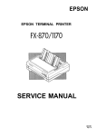
EPSON
24-PIN DOT MATRIX PRINTER
EPSON DLQ-3000+
SERVICE MANUAL
SEIKO EPSON CORPORATION
4008259
NOTICE
All rights reserved. Reproduction of any part of this manual in any form whatsoever
without SEIKO EPSON’s express written permission is forbidden.
The contents of this manual are subjects to change without notice.
All efforts have been made to ensure the accuracy of the contents of this manual.
However, should any errors be detected, SEIKO EPSON would greatly appreciate
being informed of them.
The above notwithstanding SEIKO EPSON can assume no responsibility for any errors
in this manual or the consequences thereof.
EPSON is a registered trademark of SEIKO EPSON CORPORATION.
General Notice:
Other product names used herein are for identification purposes only and may be
trademarks or registered trademarks of their respective companies.
Copyright 1997 by SEIKO EPSON CORPORATION
Nagano, Japan
ii
PRECAUTIONS
Precautionary notations throughout the text are categorized relative to 1) personal injury and 2)
damage to equipment.
WARNING
Signals a precaution which, if ignored, could result in serious or fatal personal
injury. Great caution should be exercised in performing procedures preceded by
WARNING Headings.
CAUTION
Signals a precaution which, if ignored, could result in damage to equipment.
The precautionary measures itemized below should always be observed when performing
repair/maintenance procedures.
WARNING
1. ALWAYS DISCONNECT THE PRODUCT FROM BOTH THE POWER SOURCE AND
PERIPHERAL DEVICES PERFORMING ANY MAINTENANCE OR REPAIR PROCEDURES.
2. NO WORK SHOULD BE PERFORMED ON THE UNIT BY PERSONS UNFAMILIAR WITH
BASIC SAFETY MEASURES AS DICTATED FOR ALL ELECTRONICS TECHNICIANS IN
THEIR LINE OF WORK.
3. WHEN PERFORMING TESTING AS DICTATED WITHIN THIS MANUAL. DO NOT
CONNECT THE UNIT TO A POWER SOURCE UNTIL INSTRUCTED TO DO SO. WHEN
THE POWER SUPPLY CABLE MUST BE CONNECTED, USE EXTREME CAUTION IN
WORKING ON POWER SUPPLY AND OTHER ELECTRONIC COMPONENTS.
CAUTION
1. REPAIRS ON EPSON PRODUCT SHOULD BE PERFORMED ONLY BY EPSON
CERTIFIED REPAIR TECHNICIAN.
2. MAKE CERTAIN THAT THE SOURCE VOLTAGE IS THE SAME AS THE RATED VOLTAGE,
LISTED ON THE SERIAL NUMBER/RATING PLATE. IF THE EPSON PRODUCT HAS A
PRIMARY AC RATING DIFFERENT FROM AVAILABLE POWER SOURCE, DO NOT
CONNECT IT TO THE POWER SOURCE.
3. ALWAYS VERIFY THAT THE EPSON PRODUCT HAS BEEN DISCONNECTED FROM THE
POWER SOURCE BEFORE REMOVING OR REPLACING PRINTED CIRCUIT BOARDS
AND/OR INDIVIDUAL CHIPS.
4. IN ORDER TO PROTECT SENSITIVE MICROPROCESSORS AND CIRCUITRY, USE
STATIC DISCHARGE EQUIPMENT, SUCH AS ANTI-STATIC WRIST STRAPS, WHEN
ACCESSING INTERNAL COMPONENTS.
5. REPLACE MALFUNCTIONING COMPONENTS ONLY WITH THOSE COMPONENTS BY
THE
MANUFACTURE;
INTRODUCTION
OF
SECOND-SOURCE
ICs
OR
OTHER
NONAPPROVED COMPONENTS MAY DAMAGE THE PRODUCT AND VOID ANY
APPLICABLE EPSON WARRANTY.
iii
PREFACE
This manual describes functions, theory of electrical and mechanical operations, maintenance,
and repair of DLQ-3000+.
The instructions and procedures included herein are intended for the experience repair technician,
and attention should be given to die precautions on the preceding page. The Chapters are
organized as follows:
CHAPTER 1. GENERAL DESCRIPTION
Provides a general product overview, lists specifications, and illustrates the main components of
the printer.
CHAPTER 2. OPERATING PRINCIPLES
Describes the theory of printer operation.
CHAPTER 3. DISASSEMBLY AND ASSEMBLY
Includes a step-by-step guide for product disassembly and assembly.
CHAPTER 4. ADJUSTMENT
Includes a step-by-step guide for adjustment.
CHAPTER 5. TROUBLESHOOTING
Provides EPSON-approved techniques for troubleshooting.
CHAPTER 6. MAINTENANCE
Describes preventive maintenance techniques and lists lubricants and adhesives required to
service the equipment.
APPENDIX
Describes connector pin assignments, circuit diagrams, circuit board component layout and
exploded diagram.
The contents of this manual are subject to change without notice.
iv
REVISION SHEET
Revision
Issued Data
Contents
Rev. A
August 21 1997
First Release
v
TABLE OF CONTENTS
CHAPTER 1.
CHAPTER 2.
CHAPTER 3.
CHAPTER 4.
CHAPTER 5.
CHAPTER 6.
APPENDIX
GENERAL DESCRIPTION
OPERATING PRINCIPLES
DISASSEMBLY AND ASSEMBLY
ADJUSTMENT
TROUBLESHOOTING
MAINTENANCE
vi
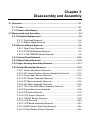
Chapter 1
Product Description
1.1 Features .................................................................................................. 1-1
1.2 Consumables and Options.................................................................... 1-3
1.3 Hardware Specification.......................................................................... 1-4
1.3.1 printing Specification.................................................................... 1-4
1.3.2 Character Specifications and Control Codes ............................. 1-7
1.3.2.1 Coded Character Sets ......................................................... 1-7
1.3.2.2 Type Faces.......................................................................... 1-7
1.3.2.3 Rendition ............................................................................. 1-7
1.3.2.4 Combination of character tables and typefaces .................. 1-8
1.3.2.5 Memory Size........................................................................ 1-9
1.3.2.6 Character Size..................................................................... 1-9
1.3.2.7 Control Codes...................................................................... 1-9
1.3.3 Paper Feed Specification............................................................ 1-10
1.3.3.1 Friction Feed (Cut sheet)................................................... 1-10
1.3.3.2 Tractor Feed (Continuous paper) ...................................... 1-10
1.3.3.3 Paper Feed Speed and Accuracy...................................... 1-10
1.3.4 Paper Specification ..................................................................... 1-11
1.3.5 Printable Area .............................................................................. 1-17
1.3.6 Paper Thickness Detection ........................................................ 1-24
1.3.7 Ribbon Cartridge ......................................................................... 1-25
1.3.7.1 Monochrome ribbon cartridge............................................ 1-25
1.3.7.2 Color ribbon cartridge ........................................................ 1-25
1.3.8 Input Data Buffer ......................................................................... 1-26
1.3.9 Electric Specifications ................................................................ 1-26
1.3.10 Safety Approvals ....................................................................... 1-26
1.3.11 CE Marking................................................................................. 1-26
1.3.12 Acoustic Noise........................................................................... 1-27
1.3.13 Reliability.................................................................................... 1-27
1.3.14 Environmental Conditions........................................................ 1-27
1.4 Interfaces .............................................................................................. 1-28
1.4.1 Parallel Interface.......................................................................... 1-28
1.4.2 Serial Interface............................................................................. 1-33
1.4.3 Optional Interface ........................................................................ 1-34
1.4.4 Printer language .......................................................................... 1-35
1.4.5 Prevention Hosts from Data Transfer Time-out ....................... 1-36
1.4.6 Interface Selection ...................................................................... 1-36
1.5 Operation .............................................................................................. 1-37
1.5.1 Control Panel ............................................................................... 1-37
1.5.1.1 Button Operations.............................................................. 1-37
1.5.1.2 Printer Status and LCD/LED Indicator Conditions............. 1-39
1.5.1.3 Printer Status and Buzzer.................................................. 1-40
1.5.2 SelecType..................................................................................... 1-41
1.5.2.1 SelecType Phase .............................................................. 1-41
1.5.2.2 SelecType Operation......................................................... 1-42
1.5.2.3 SelecType Option .............................................................. 1-43
1.5.3 Functions at Power On ............................................................... 1-45
1.5.4 Bi-D Adjustment Mode................................................................ 1-46
1.5.5 Program Reload Mode ................................................................ 1-46
1.5.6 Initialization.................................................................................. 1-47
1.5.6.1 Printer Initialization ............................................................ 1-47
1.5.6.2 Initialize Defaults to the Standard...................................... 1-48
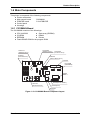
1.6 Main Components ................................................................................ 1-49
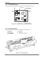
1.6.1 C210MAIN Board ......................................................................... 1-49
1.6.2 C124PSB/PSE Board................................................................... 1-50
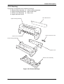
1.6.3 Printer Mechanism ...................................................................... 1-50
1.6.4 Housing ........................................................................................ 1-51
Product Description
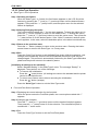
1.1 Features
The DLQ 3000+, equipped with a Bi-directional parallel interface, is the most advanced
EPSON 24-pin impact-dot printer. It prints on continuous multi-part form as well as on single
sheet, which makes the printer highly usable in office environment . The main features of
this printer are:
Used in Network environment with parallel interface supported
Memory
CSF paper quantity sensor
Paper jam detection
Enhanced duplex printing
1 original plus 6 duplications in the copy mode
Wide printable area
70 line / A4 (0 mm can be set for the top and bottom margins at single print mode.)
Paper thickness detection function supported
Enables the auto and manual platen gap adjustment
Fonts
Bitmap fonts:
Scalable fonts:
Bar-code fonts:
9 LQ and 1 draft typefaces
4 typefaces
8 typefaces
Character tables
Standard version:
NLSP version:
11 tables
30 tables
Control codes
ESC/P2
IBM 2391 Plus Emulation
Input buffer
128 K byte
Interface
Bi-directional parallel interface (IEEE-1284 nibble mode supported)
Serial interface (EIA-232D)
Type-B interface level 2 (Optional)
Reliability
Total print volume:
Printhead life:
Ribbon life:
Rev. A
9 million lines
200 million strokes
6 million characters
1-1
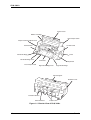
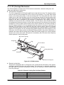
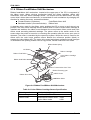
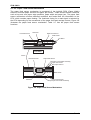
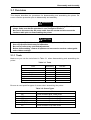
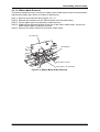
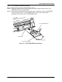
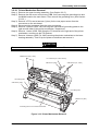
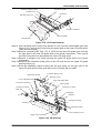
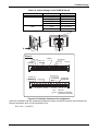
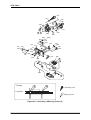
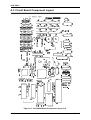
DLQ-3000+
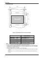
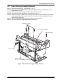
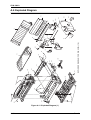
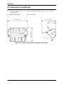
Printer Cover
Ribbon Cartridge
Rear Paper Guide
Paper Thickness Adjust Lever
Control Panel
Power Switch
Knob
Left Guide Edge
Left Guide Edge Lock
Printhead
Front Paper Guide
Paper Bail
Right Guide Edge Lock
Right Guide Edge
Paper Support
Release Lever
Parallel Interface
Serial Interface
Tractor Unit
Figure 1-1. Exterior View of DLQ 3000+
1-2
Rev. A
Product Description
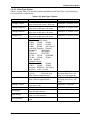
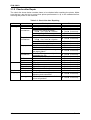
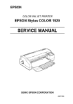
1.2 Consumables and Options
Table 1-1. Accessories and Options
Part Number
Consumable Supplies
S015066
S015067
Optional Equipment
C806830
C82307∗ / C82308∗
C82310∗ / C82311∗
C82312∗
C82313∗
C82314∗
C82315∗
C82331∗
C82345*
C82346
Accessory Equipment
Description
Ribbon cartridge (Black)
Ribbon cartridge (Color)
Cut sheet feeder
32KB intelligent serial I/F card
32KB intelligent parallel I/F card
Localtalk™ card
32KB IEEE-488 I/F card
Coax I/F card
Twin-Ax I/F card
Ethernet I/F card
IEEE-1284 parallel I/F card
Multi Protocol Ethernet I/F card
Power supply cable*
2
Note:
1. Asterisk at the end of the part numbers replaces the last digit of the part number,
which varies by the market.
2. Can be an accessory item according as market.
Rev. A
1-3
DLQ-3000+
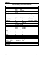
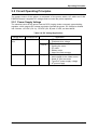
1.3 Hardware Specification
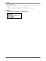
1.3.1 printing Specification
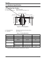
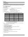
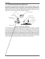
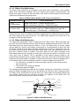
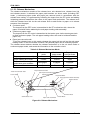
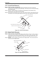
Print method
Print pin arrangement
Impact-dot matrix
24-pin rhombus (See Figure 1-2.)
0 .8 6 m m = 1 /3 0 "+ 1 /2 1 6 0 "
6 x 0 .0 2 3 m m (= 1 -1 0 8 0 ")
6 x 0 .0 2 3 m m (= 1 -1 0 8 0 ")
# 2 4
1 1 x 0 .2 8 m m (= 1 /9 0 ")
# 2 3
# 2
0 .1 4 m m (= 1 /1 8 0 ")
1 1 x 0 .2 8 m m (= 1 /9 0 ")
3 .2 5 m m (= 1 /1 8 0 "x 2 3 )
# 1
Figure 1-2. Pin Arrangement
Printing direction
Resolution
Bi-directional printing with logic seeking
See Table 1-2.
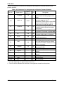
Table 1-2 .Printing Resolution
Printing Mode
Horizontal Density
Vertical Density
Adjacent Dot Print
High speed draft
Draft
Draft condensed
LQ
8-pin bit image
90 dpi
180 dpi
No
120 dpi
180 dpi
No
240 dpi
180 dpi
No
360 dpi
180 dpi
No
60, 80, 90 or 120 dpi
60 dpi
Yes
120 or 240 dpi
60 dpi
No
24-pin bit image
60, 90, 120 or 180
180 dpi
Yes
dpi
360 dpi
180 dpi
No
Raster graphics
180 or 360 dpi
180 or 360 * dpi
Yes
Note: When a color ribbon is installed, the printer can not print vertical 360 dpi graphics. In
that case, the printer changes vertical density to 180 dpi.
1-4
Rev. A
Product Description
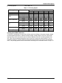
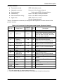
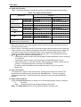
Printing speed
See Table 1-3.
Table 1-3. Printing Speed
Printing Mode
High speed draft
Draft
Craft condensed
LQ
LQ condensed
Raster (360 dpi)
Character Size
10 cpi
10 cpi
12 cpi
15 cpi
17 cpi
20 cpi
10 cpi
12 cpi
15 cpi
17 cpi
20 cpi
10 cpi
Maximum Printing Speed
Mode 0
Mode 1
Mode 2
Mode 3
Mode 4
444
360
432
540
309
360
120
144
180
206
240
20
444
333
400
500
286
333
111
133
167
190
222
20
160
240
288
360
206
240
80
96
120
137
160
20
160
120
144
180
103
120
40
48
60
68
80
20
240
180
216
270
154
180
60
72
90
103
120
20
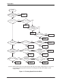
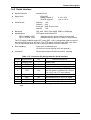
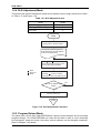
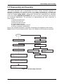
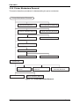
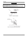
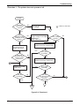
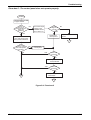
Printing Speed Mode Selection
This printer is designed to control the printing speed according to the power supply voltage
and printhead temperature. When the power supply voltage drops to the limit, the printer
stops printing, then resumes the job at a slower speed to print the remaining data for the
line. When the printhead temperature rises to the limit, the printer stops printing. Then it
resumes printing at a slower speed if the printhead temperature recovers to the specified
level. The printing speed mode is determined according to the flowchart shown in Page 1-6.
Rev. A
1-5
DLQ-3000+
S T A R T
Is th e
h e a d te m p e ra tu re
<1 2 C ?
Y E S
M o d e 4
N O
P -D o w n * ?
Y E S
B la c k c o lo r p r in t?
Y E S
N O
N O
M o d e 2
Is p a p e r
th ic k n e s s
>
= 0 .1 9 m m ?
Y E S
N O
M o d e 2
C o p y 2 m o d e ?
N O
Is p r in t d u ty
>
= 5 0 % ?
N O
Y E S
Is th e h e a d
te m p e ra tu re
>
=3 8 C ?
N O
N O
N O
B la c k c o lo r p r in t?
N O
Y E S
B la c k c o lo r p r in t?
B la c k c o lo r p r in t?
Y E S
M o d e 2
Is p a p e r
th ic k n e s s
>
= 0 .1 9 m m ?
N O
Y E S
M o d e 0
Y E S
M o d e 0
Y E S
M o d e 2
Is p a p e r
th ic k n e s s
>
= 0 .1 9 m m ?
N O
Is p a p e r
th ic k n e s s
>
= 0 .1 9 m m ?
N O
C o p y 2 m o d e ?
N O
Y E S
M o d e 3
M o d e 2
Y E S
M o d e 1
M o d e 0
Y E S
M o d e 1
M o d e 0
Y E S
M o d e 3
M o d e 2
P - D o w n : M e a n s th a t th e lin e is th e r e p r in te d lin e a fte r th e p o w e r s u p p ly v o lta g e d r o p s . It is to p r e v e n t
th e p r in th e a d a n d th e p r in te r m e c h a n is m fr o m b e in g d r iv e n u n d e r th e im p r o p e r p o w e r
s u p p ly v o lta g e .
Figure 1-3. Printing Speed Selection Mode
1-6
Rev. A
Product Description
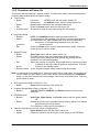
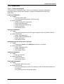
1.3.2 Character Specifications and Control Codes
1.3.2.1 Coded Character Sets
ASCII international and Legal international character sets *
USA
France
Germany
UK
Denmark 1
Sweden
Italy
Spain 1
Japan
Norway
Denmark 2
Spain 2
Latin America
Korea
Legal
Note: The codes for the international and legal characters are as follows:
23H, 24H, 40H, 5BH, 5CH, 5DH, 5EH, 60H, 7BH, 7CH, 7DH, 7EH
Standard version (11 character tables)
Italic table
PC850 (Multilingual)
PC861 (Icelandic)
PC865 (Nordic)
BRASCII
ISO Latin 1
PC437 (US, Standard Europe)
PC860 (Portuguese)
PC863 (Canadian French)
Abicomp
Roman 8
NLSP version (30 character tables)
Italic table
PC 437 (US, Standard Europe)
PC 850 (Multilingual)
PC 437 (Greek)
PC 852 (East Europe)
PC 853 (Turkish)
PC 855 (Cyrillic)PC 860
PC 857 ( Turkish)
PC 866 (Russian)
PC 869 (Greek)
MAZOAWIA (Poland)
Code MJK (CSFR)
ISO 8559-7 (Latin, Greek)
ISO Latin 1T (Turkish)
Bulgaria (Bulgaria)
PC 864 (Arabic)
Estonia
PC 774 (LST 1283:1933)
ISO 8859-2
PC 866 LAT. (Latvian)
PC 860 (Portuguese)
PC 861 (Icelandic)
PC 865 (Nordic)
PCAPTEC (Arabic)
PC 708 (Arabic)
PC 720 (Arabic)
1
PCAR864 (Arabic)
Hebrew7 *
1
1
Hebrew8 *
PC862(Hebrew) *
Note 1: Theses character tables are not selected in the SelecType mode.
1.3.2.2 Type Faces
Bitmap fonts (10 type faces)
Roman
Sans Serif
Script
Script C
Orator
Orator S
Scalable fonts (4 type faces)
Roman
Sans Serif
Bar-code fonts (8 type faces)
EAN 13
EAN-8
UPC-E
Code 39
Courier
OCR B
Draft
Prestige
Roman T
Sans Serif H
Interleaved 2 of 5
Code 128
UPC-A
POSTNET
1.3.2.3 Rendition
ASCII
Double-width
Double-height
Condensed
Bolded
Double-strike
Italics
Super/subscript
Outlined
Shadowed
Underlined (Single, Double, Single-broken, Double-broken line)
Strike-through (Single, Double, Single-broken, Double-broken line)
Over-scored (Single, Double, Single-broken, Double-broken line)
Rev. A
1-7
DLQ-3000+
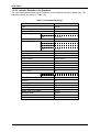
1.3.2.4 Combination of character tables and typefaces
Table 1-4. Character Tables and Type Faces
Character Tables
Standard
version *1
NLSP
1
version *
Italic table
PC 437 (US Standard Europe)
PC 850 (Multilingual)
PC 860 (Portuguese))
PC 861 (Icelandic)
PC 863 (Canadian-French)
PC 865 (Nordic)
BRASCII
Abicomp
Roman 8
ISO Latin 1
Italic table
PC 437 (US Standard Europe)
PC 850 (Multilingual)
PC 860 (Portuguese)
PC861 (Icelandic)
PC 865 (Nordic)
PC 864 (Arabic)
PC 437 (Greek)
PC 852 (East Europe)
PC 853 (Turkish)
PC 855 (Cyrillic)
PC 857 (Turkish)
PC 866 (Russian)
PC 869 (Greek)
MAZOWIA (Poland)
Code MJK (CSFR)
ISO 8859-7 (Latin/Greek)
ISO Latin 1T (Turkish)
Bulgaria (Bulgaria)
Estonia
PC 774 (LST 1283:1993)
ISO 8859-2
PC 866 LAT. (Latvian)
PCAPTEC (Arabic)
PC 708 (Arabic)
PC 720 (Arabic)
PCAR864 (Arabic)
2
Hebrew7 *
2
Hebrew8 *
2
PC862(Hebrew) *
Bitmap Fonts
Scalable Fonts
EPSON Draft
EPSON Roman
EPSON Sans Serif
EPSON Courier
EPSON Prestige
EPSON Script
EPSON OCR-B
EPSON Orator
EPSON Orator-S
Epson Script C
EPSON Roman
EPSON Sans Serif
EPSON Roman T
EPSON Sans Serif H
EPSON Draft
EPSON Roman
EPSON Sans Serif
EPSON Courier
EPSON Prestige
EPSON Script
EPSON OCR-B
EPSON Orator
EPSON Orator-S
Epson Script C
EPSON Draft
EPSON Roman
EPSON Draft
EPSON Roman
EPSON Sans Serif
EPSON Courier
EPSON Prestige
EPSON Script
EPSON Roman
EPSON Sans Serif
EPSON Roman T
EPSON Sans Serif H
EPSON Draft (Arabic)
EPSON Naskh
(Roman)
EPSON Kufi (Sans Serif)
(Not supported)
EPSON Draft (Hebrew)
EPSON Miriam (Roman)
EPSON David
(Courier)
(Not supported)
(Not supported)
(Not supported)
Note:
1: ESC R command is effective on the character tables with bold weight.
2: These character tables are not selected in the SelecType mode.
1-8
Rev. A
Product Description
1.3.2.5 Memory Size
Input buffer
Download memory
CG ROM
128 K byte or 1k byte
Approximately 10 K byte
NLSP Version: 8 M bit,
Standard Version: 4 M bit
1.3.2.6 Character Size
Character size
• Bit map font
• Scalable font
Character matrixes
10.5 point
10.5 point
See Table 1-5.
Table 1-5. Character Matrixes
Character
Horizontal Dots
Vertical Dots
Draft 10 cpi
Draft 12 cpi
Draft 15 cpi
LQ 10 cpi
LQ 12 cpi
LQ 15 cpi
LQ proportional
12
10
8
36
30
24
48 (maximum)
24
24
16
24
24
16
24
Notes:
1. The character matrixes for high speed draft 10 cpi characters are made from the draft
12 cpi matrixes.
2. The character matrixes for 15 cpi character are also used for superscript and
subscript characters.
1.3.2.7 Control Codes
ESC/P2
IBM 2391 Plus Emulation
Rev. A
1-9
DLQ-3000+
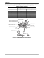
1.3.3 Paper Feed Specification
1.3.3.1 Friction Feed (Cut sheet)
Paper Path
• Single sheet, envelopes
Front and rear insertion (Manual/CSF insertion)
• Multi-part form
Rear entry (Manual/CSF insertion)
Notes:
1. Set the release lever to “FRICTION”.
2. Do not load continuous paper (including folding paper).
3. Set the longer side of the envelope horizontally.
4. When setting No.6 envelope, align the left sheet edge guide with the marked position.
1.3.3.2 Tractor Feed (Continuous paper)
Paper Path
• Rear entry push tractor feed with paper parking function
Notes:
1. Set the release lever to “TRACTOR”.
2. Do not perform reverse feed for more than 1/6 inch.
3. Set the left and right sheet edge guides to the right and left ends of the front paper
guide, respectively.
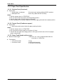
1.3.3.3 Paper Feed Speed and Accuracy
Minimum feed length
1/360 inch (1/6, 1/8 or programmable with the
increment of 1/360 inch)
Feed speed
• 1/6 inch line feed
• Continuous feed
1-10
42 ms
6.0 IPS (inch/second)
0.152 MPS (m/second)
Rev. A
Product Description
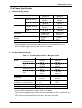
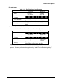
1.3.4 Paper Specification
Cut sheet (Single sheet)
Table 1-6. Cut sheet Specification : Single Sheet
Minimum
Width
Manual insertion
CSF
Length
Manual insertion
CSF
Thickness
Weight
Maximum
3.6 inch
16.5 inch
92 mm
420 mm
3.9 inch
16.5 inch
100 mm
420 mm
3.5 inch
16.5 inch
92 mm
420 mm
3.6 inch
14.3 inch
92 mm
364 mm
0.0025 inch
0.0047 inch
0.065 mm
0.12 mm
52 g/m²
105 g/m²
14 lb.
27 lb.
Plain paper, Reclaimed paper
Quality
Notes:
1. Reclaimed paper can be used under condition of room temperatures only.
2. Ensure that the paper is not curled, folded or crumpled.
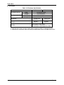
Cut sheet (Multi-part form)
Table 1-7. Cut sheet Specification : Multi-part Form
Minimum
Width
Maximum
3.6 inch
16.5 inch
92 mm
420 mm
3.9 inch
16.5 inch
CSF
100 mm
420 mm
Length
3.5 inch
16.5 inch
Manual insertion
1
92 mm
420 mm *
3.6 inch
14.3 inch
CSF
1
92 mm
364 mm *
Copies
1 original and 6 copies
0.0047 inch
0.021 inch
Thickness
0.12 mm
0.53 mm
Weight
40 g/m²
58 g/m²
11 lb.
15 lb.
(I sheet of a multi-part form)
Quality
Carbon-less multi-part paper
Jointing
Line glue (top, right and left side)
Notes:
1. Ensure that the paper is not curled, folded or crumpled.
2. The maximum length for the carbon-less multi-part paper is 297 mm with the left or
right side of the form line-glued.
3. CSF does not feed paper which is glued by the right or left side.
Rev. A
Manual insertion
1-11
DLQ-3000+
Envelopes
Table 1-8. Envelope Specification
Minimum
Envelopes (No.6)
Envelopes (No.10)
Thickness
Weight
Quality
Width
Length
Width
Length
Maximum
6.5 inch/165 mm
3.6 inch/92 mm
9.5 inch/241 mm
4.1 inch/105 mm
0.0063 inch
0.021 inch
0.16 mm
0.52 mm
45 g/m²
91 g/m²
12 lb. /m²
24 lb./m²
Bond paper, Plain paper
Airmail paper without glue at a flap
Notes:
1. Fold the flap of the envelope inside before loading at CSF or manual insertion.
2. Difference in thickness within the same printable area must be 0.0098 inch or less.
1-12
Rev. A
Product Description
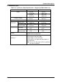
Continuous paper
Table 1-9. Continuous Paper Specification : Single Paper/Multi-Part Form
Minimum
Width
Length (1 page)
Copies
Total
Thickness
Single sheet
1 sheet of
multi-part form
Weight
Cut sheet
1 sheet of
multi-part form
Quality
Jointing *
Rev. A
1
Maximum
4.0 inch
16 inch
101.6 mm
406.4 mm
4.0 inch
22.0 inch
101.6 mm
558.8 mm
3.5 inch
16.4 inch
1
92 mm
420 mm *
1 original and 6 copies
0.0025 inch
0.047 inch
0.065 mm
0.12 mm
0.0047 inch
0.021 inch
0.12 mm
0.53 mm
52.3 g/m²
105 g/m²
14 lb.
27 lb.
40 g/m²
58 g/m²
11 lb.
15 lb.
Plain paper, Reclaimed paper
Carbon-less multi-part form
Must be one of the followings:
- Point glue on the both sides
- Tape staple on the both sides
- Point glue on one side and tape staple on
the other side
Note: Do not use the paper which is glued by
the side or stapled.
1-13
DLQ-3000+
Labels
Table 1-10. Label Specification
Minimum
Label size
Base sheet width
Base sheet length
(1 page)
Base sheet thickness
Total thickness
Label weight
Quality
Maximum
See Figure 1-4.
4.0 inch
16.0 inch
101.6 mm
406.4 mm
4.0 inch
22.0 inch
101.6 mm
559 mm
0.0028 inch
0.0035 inch
0.07 mm
0.09 mm
0.0063 inch
0.0075 inch
0.16 mm
0.19 mm
64 g/m²/17 lb.
Plain paper or equivalent
The base sheet must be continuous paper.
Notes:
1. Use labels in the condition of the room temperature only.
2. Labels backed with the continuous base sheet can be used only.
3. When the label sheet whose base sheet is exposed around the labels, adjust the
platen gap manually to the portion covered with the label using PG adjust lever.
2 - 1 /2 in c h
(6 3 .5 m m o r m o re )
1 5 /1 6 in c h
(2 3 .8 m m o r m o re )
R 0 .1 in c h ( R 2 .5 m m
o r m o re )
Figure 1-4. Label Size
1-14
Rev. A
Product Description
Pre-print paper
Table 1-11. Pre-Print Paper Specification
Minimum
Width
Length
(1 page)
Total thickness
Quality
Maximum
4.0 inch
16.0 inch
101.6 mm
406.4 mm
4.0 inch
22.0 inch
101.6 mm
559 mm
0.0025 inch
0.047 inch
0.065 mm
0.12 mm
The paper printed with the color which has
the reflective rate of less than 60 %, such as
black.
Continuous forms with labels
Table 1-12. Continuous Forms with Labels Specification
Minimum
Base sheet width
Base sheet length
(1 page)
Total thickness
Quality
Maximum
4.0 inch
16.0 inch
101.6 mm
406.4 mm
4.0 inch
22.0 inch
101.6 mm
559 mm
–
0.021 inch
–
0.53 mm
Plain paper or equivalent
Airmail paper without glue at a flap
Note:
When using the continuous forms with labels, the label position must be registered
properly. It can be performed through the utility “Label Position Registering Utility”.
Rev. A
1-15
DLQ-3000+
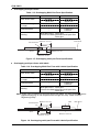
Overlapping multi-part forms
Table 1-13. Overlapping Multi-Part Form Specification
Minimum
Base sheet width
Base sheet length
(1 page)
Total thickness
Jointing
T o ta l T h ic k n e s s
Maximum
4.0 inch
16.0 inch
101.6 mm
406.4 mm
4.0 inch
22.0 inch
101.6 mm
559 mm
–
0.026 inch
–
0.65 mm
Multi-part forms :Point glue
Joint for the base sheet and multi-part form
:Point glue
M a x im u m
1 3 .3 m m
B a s e S h e e t
M a x im u m
G lu e
M a x im u m
3 .3 m m
1 7 m m
Figure 1-5. Overlapping multi-part Form Specification
Overlapping multi-part forms with labels
Table 1-14. Overlapping Multi-Part Form with Labels Specification
Minimum
Maximum
Base sheet width
4.0 inch
16.0 inch
101.6 mm
406.4 mm
Base sheet length
4.0 inch
22.0 inch
(1 page)
101.6 mm
559 mm
–
0.026 inch
Total thickness
–
0.65 mm
Multi-part forms :Point glue
Jointing
Joint for the base sheet and multi-part form
:Point glue
Note: When using overlapping multi-part forms with labels, the label position must be
registered properly. It can be performed through the utility “Label Position
Registering Utility”.
T o ta l T h ic k n e s s
M a x im u m
1 3 .3 m m
L a b e l
M a x im u m
G lu e
3 .3 m m
M a x im u m
M a x im u m
B a s e S h e e t
0 .5 3 m m
1 7 m m
Figure 1-6. Overlapping multi-part Form with Labels Specification
1-16
Rev. A
Product Description
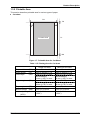
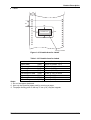
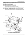
1.3.5 Printable Area
This section describes printable area for various types of paper.
Cut sheet
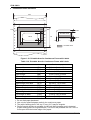
P W
T M
R M
L M
P r in ta b le A r e a
P L
B M
Figure 1-7. Printable Area for Cut Sheet
Table 1-15. Printing Area for Cut sheet
Single cut sheet
Paper width
Paper length
Left margin
(PW)
(PL)
(LM)
Right margin
(RM)
Top margin
(TM)
Bottom margin (BM)
Width of printing area
Refer to Section 1.3.4.
Refer to Section 1.3.4.
3 mm (0.118”) or more
[A3 landscape]
31 mm (1.22”) or more
3 mm (0.118”) or more
[A3 landscape]
20 mm (0.78”) or more
0 mm (0”) or more
0 mm (0”) or more
Maximum 346 mm
(13.62”)
Multi-part cut sheet
Refer to Section 1.3.4.
Refer to Section 1.3.4.
3 mm (0.118”) or more
[A3 landscape]
31 mm (1.22”) or more
3 mm (0.118”) or more
[A3 landscape]
20 mm (0.78”) or more
0 mm (0”) or more
0 mm (0”) or more
Maximum 346 mm
(13.62”)
(WPA)
Rev. A
1-17
DLQ-3000+
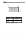
Continuous paper
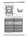
P W
L M
R M
P e r fo r a tio n
T M
P r in ta b le A r e a
P e r fo r a tio n
P L
B M
Figure 1-8. Printable Area for Continuous Paper
Continuous paper
Paper width
Paper length
Left margin
Right margin
Top margin
Bottom margin
(PW)
(PL)
(PM)
(LM)
(TM)
(BM)
Refer to Section 1.3.4.
Refer to Section 1.3.4.
9 mm (0.354”) or more
9 mm (0.354”) or more
4.2 mm (0.165”) or more
4.2 mm (0.165”) or more
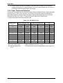
Notes:
1. In the top 75 mm are, the paper feeding pitch may be irregular.
2. Forms-override printing is available for 2 lines after the paper end is detected.(Paper
feeding pitch is not guaranteed.) The end of the printable area is 4.2 m or more apart
from the bottom edge of the paper.
3. When the page width is 16 inches, note the followings:
• LM is 18 mm or more with the left tractor set at the farthest side toward the 136th
column.
• RM is 18 mm or more with the right tractor set at the farthest side toward the 1st
column.
1-18
Rev. A
Product Description
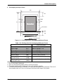
Labels
L M
T M
T O L
L O L
P r in ta b le A r e a
R O L
B O L
P r in tin g p r o h ib ite d
Figure 1-9. Printable Area for Labels
Table 1-16. Printable Area for Labels
Continuous paper
Paper width
(PW)
Paper length
(PL)
Left margin
(LM)
Top margin
(TM)
Left margin on label (LOL)
Right margin on label (ROL)
Top margin on label (TOL)
Bottom margin on label (BOL)
Refer to Section 1.3.4.
Refer to Section 1.3.4.
12 mm (0.472”) or more
1.2 mm (0.0472) or more
3 mm (0.118”) or more
3 mm (0.118”) or more
3 mm (0.118”) or more
3 mm (0.118”) or more
Notes:
1. Do not feed paper backward.
2. Use only the specified paper path for continuous paper.
3. The paper feeding pitch in the top 75 mm (2.9”) may be irregular.
Rev. A
1-19
DLQ-3000+
Envelops
P r in t D ir e c tio n
( M a n u a l in s e r tio n fr o m th e r e a r /C S F )
L M
R M
T M
P r in ta b le A r e a
B M
P r in t D ir e c tio n
( M a n u a l in s e r tio n fo r m
th e fro n t)
Figure 1-10. Printable Area for Envelopes
Table 1-17. Printable Area for Envelops
Continuous paper
Paper width
Paper length
Left margin
Right margin
(PW)
(PL)
(LM)
(RM)
Top margin
(TM)
Refer to Section 1.3.4.
Refer to Section 1.3.4.
3 mm(0.118”) or more
3 mm(0.118”) or more
1
0 mm (0”) or more *
Bottom margin
(BM)
0 mm (0”) or more
Note 1: At CSF insertion: 4.2 mm (0.16”) or more
1-20
Rev. A
Product Description
Overlapping multi-part forms
P W
T M
L M B
P L
R M B
R M
L M
P r in ta b le A r e a
P e r fo r a tio n
B M
T M
: P r in ta b le A r e a
Figure 1-11. Printing Area for Overlapping Multi-part Forms
Table 1-18. Printing Area for Overlapping Multi-part Forms
Continuous paper
Paper width
(PW)
Refer to Section 1.3.4.
Paper length
(PL)
Refer to Section 1.3.4.
Left margin
(LM)
19 mm (0.748”) or more
Right margin
(RM)
19 mm (0.748”) or more
Top margin
(TM)
21.2 mm (0.835”) or more
Bottom margin
(BM)
4.2 mm (0.165”) or more
Left margin from the multi-part form to 13 mm (0.512”) ± 3 mm (0.118”)
the base sheet
(LMB)
Right margin from the multi-part form 13 mm (0.512”) ± 3 mm (0.118”)
to the base sheet
(RMB)
Notes:
1. Do not feed paper backward.
2. Use only the specified paper path for continuous paper.
3. The paper feeding pitch in the top 75 mm (2.9”) may be irregular.
4. Forms-override printing is available for 2 lines after the paper end is detected. The end of
the printable area is 4.2 mm or more apart from the bottom edge of the paper.
Rev. A
1-21
DLQ-3000+
Continuous forms with labels
P W
T M
L M
T F L
R M
T O L
N o n - p r in ta b le A r e a
P r in ta b le A r e a
L a b e l
P L
B O L
B F L
L O L
L F L
R F L
R O L
: P r in ta b le A r e a
B M
Figure 1-12. Printable Area for Continuous Forms with Labels
Table 1-19. Printable Area for Continuous Forms with Labels
Continuous paper
Paper width
(PW)
Refer to Section 1.3.4.
Paper length
(PL)
Refer to Section 1.3.4.
Left margin
(LM)
9 mm (0.354”) or more
Right margin
(RM)
9 mm (0.354”) or more
Top margin
(TM)
4.2 mm (0.165”) or more
Bottom margin
(BM)
4.2 mm (0.165”) or more
Left margin for label
(LFL)
45 mm (1.77) or more
Right margin from label
(RFL)
45 mm (1.77) or more
Top margin from label
(TFL)
25 mm(0.984”) or more
Bottom margin from label
(BFL)
25 mm(0.984”) or more
Left margin on label
(LOL)
3 mm (0.118”) or more
Right margin on label
(ROL)
3 mm (0.118”) or more
Top margin on label
(TOL)
3 mm (0.118”) or more
Bottom margin on label
(BOL)
3 mm (0.118”) or more
Notes:
1. Do not feed paper backward.
2. Use only the specified paper path for the continuous paper.
3. The paper feeding pitch in the top 75 mm (2.9”) may be irregular.
4. Forms-override printing is available for 20 lines after the paper end is detected.
(Paper feeding pitch is not guaranteed.) The end of the printable are is 4.2 mm or
more apart from the bottom edge of the paper.
1-22
Rev. A
Product Description
Overlapping multi-part forms with labels
P W
T M
L M B
P L
R M B
P r in ta b le A r e a
L M
L O L
R O L
R M
T F L
T O L
L F L
L a b e l
R F L
P e r fo r a tio n
P r in ta b le A r e a
B O L
B F L
B M
L a b e l
T M
: P r in ta b le A r e a
Figure 1-13. Printable Area for Overlapping Multi-Part Forms with Labels
Table 1-20. Printable Area for Overlapping Multi-Part Forms
Continuous paper
Paper width
(PW)
Refer to Section 1.3.4.
Paper length
(PL)
Refer to Section 1.3.4.
Left margin
(LM)
19 mm (0.748”) or more
Right margin
(RM)
19 mm (0.748”) or more
Left margin from the multi-part forms
13 mm (0.552”) ± 3 mm (0.118”)
to the base sheet
(LMB)
Right margin from the multi-part forms 13 mm (0.552”) ± 3 mm (0.118”)
to the base sheet
(RMB)
Top margin
(TM)
21.2 mm (0.835”) or more
Bottom margin
(BM)
4.2 mm (0.165”) or more
Non-printable area
(NA)
25.4 mm (1.0”) or more
Left margin from label
(LFL)
45 mm (1.77”) or more
Right margin from label
(RFL)
45 mm (1.77”) or more
Top margin from label
(TFL)
25 mm(0.984”) or more
Bottom margin from label
(BFL)
25 mm(0.984”) or more
Left margin on label
(LOL)
3 mm (0.118”) or more
Right margin on label
(ROL)
3 mm (0.118”) or more
Top margin on label
(TOL)
3 mm (0.118”) or more
Bottom margin on label
(BOL)
3 mm (0.118”) or more
Notes:
1. Do not feed paper backward.
2. The paper feeding pitch in the top 75 mm (2.9”) may be irregular.
Rev. A
1-23
DLQ-3000+
3. Forms-override printing is available for 20 lines after the paper end is detected.
(Paper feeding pitch is not guaranteed.) The end of the printable are is 4.2 mm or
more apart from the bottom edge of the paper
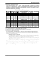
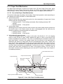
1.3.6 Paper Thickness Detection
This printer is equipped with the automatic paper thickness adjust function. When the paper
thickness lever is set to “Auto position”, the printer automatically measures thickness of
each paper loaded to set the proper PG (platen Gap) the detected thickness. PG is also
adjusted manually. See Table 1-21 which shows the adjust lever position and
corresponding paper thickness and platen gap.
Table 1-21. PG Adjust Lever
Adjust lever
position
Paper thickness (inch)
Paper thickness (mm)
Maximum
Maximum
Minimum
Minimum
PG
Inch
mm
-1
0.0024
0.0043
0.06
0.11
0.0138
0.35
0
0.0024
0.0043
0.06
0.11
0.0154
0.39
1
0.0043
0.0059
0.11
0.15
0.0169
0.43
2
0.0059
0.0075
0.15
0.19
0.0181
0.46
3
0.0075
0.0098
0.19
0.25
0.0197
0.50
4
0.0098
0.0122
0.25
0.30
0.0217
0.55
5
0.0122
0.0146
0.30
0.36
0.0240
0.61
6
0.0146
0.0165
0.36
0.42
0.0264
0.67
7
0.0165
0.0185
0.42
0.46
0.0280
0.71
8
0.0185
0.0201
0.46
0.49
0.0291
0.74
9
0.0201
0.0217
0.49
0.53
0.0307
0.78
Notes: Switching to “Dark” in the copy mode is effective under the following conditions:
In the “Auto” mode:
Paper thickness is 0.2 mm or more.
Manual adjustment:
The lever is set to one of the positions in the range from
3 to 9.
1-24
Rev. A
Product Description
1.3.7 Ribbon Cartridge
1.3.7.1 Monochrome ribbon cartridge
Color
Black
Ribbon fabric
Nylon 66
Ribbon dimension
25.5 mm (W) X 17 mm (L) X 1.5 mm (D)
ribbon thickness
0.128 mm ± 0.007 mm
Cartridge dimension
153 mm/6.0” (W) X 33 mm/1.3” (H) X 105 mm/4.1” (D)
Ribbon life *
6 million characters
Ribbon replacement
Whole cartridge
Item No.
S015066
∗ At 10 cpi printing in the LQ mode. (48 dots per character)
1.3.7.2 Color ribbon cartridge
Color
Ribbon fabric
Ribbon dimension
ribbon thickness
Cartridge dimension
Ribbon life *
Black Magenta, Cyan, Yellow
Nylon 66
25.5 mm (W) X 17 mm (L) X 1.5 mm (D)
0.128 mm ± 0.007 mm
153 mm/6.0” (W) X 33 mm/1.3” (H) X 105 mm/4.1” (D)
Black:
1.5 million characters
Magenta 1.1 million characters
Cyan
1.1 million characters
Yellow
0.8 million characters
Ribbon replacement
Whole cartridge
Item No.
S015067
∗ At 10 cpi printing in the LQ mode. (48 dots per character)
Rev. A
1-25
DLQ-3000+
1.3.8 Input Data Buffer
Approximately 128 K byte/1K byte
1.3.9 Electric Specifications
120 V version
Rated voltage
Input voltage range
Rated frequency renege
Input frequency range
Rated current
Power consumption
Insulation resistance
Dielectric strength
220 - 240V version
Rated voltage
Input voltage range
Rated frequency renege
Input frequency range
Rated current
Power consumption
Insulation resistance
Dielectric strength
AC 120 V
AC 103.5 to 132 V
50 to 60 Hz
49.5 to 60.5 Hz
7 A (maximum)
Approximately 60 W (ISO/IEC 10561 Letter pattern)
Energy Star program compliant
10 M ohms minute
(Between AC line and chassis, 500 VDC)
AC 1,000 V rms. for 1 minute or
AC 1,200 V rms. for 1 second
(Between AC line and chassis)
AC 220 to 240 V
AC 198 to 264 V
50 to 60 Hz
49.5 to 60.5 Hz
0.7 A (maximum)
Approximately 60 W (ISO/IEC 10561 Letter pattern)
Energy Star program compliant
10 M ohms min.
(Between AC line and chassis, DC 500 V)
AC 1,500 Vrms. For 1 minute
(Between AC line and chassis)
1.3.10 Safety Approvals
120 V version
Safety standards
EMI
220 - 240 V version
Safety standards
EMI
UL1950 with D3
CSA22.2 No. 950 with D3
FCC part15 subpart B class B
CSA C108.8 class B
EN 60950 (TÜV, NEMKO)
EN 55022 (CISPR Pub.22) class B
AS/NZS 3548 class B
1.3.11 CE Marking
220 - 240 V version
Low Voltage Directive 73/23/EEC
EMC Directive 89/336/EEC
1-26
EN60950
EN55022 class B
EN61000-3-2
EN61000-3-3
EN50082-1
IEC801-2
IEC801-3
IEC801-4
Rev. A
Product Description
1.3.12 Acoustic Noise
Noise level
Approximately 55 dB (A) (According to ISO 7779)
1.3.13 Reliability
Total print volume
Printhead life
9 million lines (excluding printhead)
200 million strokes/pin (Monochrome ribbon)
100 million strokes/pin (Color ribbon)
Ribbon life
• Fabric black ribbon life
• Fabric color ribbon
6 million characters*
Black :
1.5 million characters*
Magenta: 1.1 million characters*
Cyan:
1.1 million characters*
Yellow:
0.8 million characters*
* 1 character is formed with 48 dots.
At 10-cpi printing (LQ mode)
1.3.14 Environmental Conditions
Table 1-22. Environmental Condition
Operating
5 to 35 °C
1
Temperature
15 to 35 °C *
2
15 to 25 °C *
10 to 80 %
3
1
Humidity *
10 to 80 % *
2
20 to 60 % *
Resistance to shock
0.25G, 10 to 55 Hz
(Directions: X,Y and Z)
Resistance to Vibration 1G, Within 1 ms
(Directions: X,Y and Z)
Notes:
1. When the optional film ribbon is used.
2. When the envelopes or labels are printed.
3. Without condensation
Rev. A
Non-operating
-30 to 65 °C
1
-20 to 40 °C *
5 to 85 %
1
5 to 85 % *
0.50G, 10 to 55 Hz
(Directions: X,Y and Z)
2G, Within 1 ms
(Directions: X,Y and Z)
1-27
DLQ-3000+
1.4 Interfaces
The EPSON DLQ-3000+ is equipped with the parallel and Mac serial interfaces and a card
slot for an optional Type-B interface. This section provides information on each interface.
1.4.1 Parallel Interface
Forward Channel
Transmission mode
8 bit parallel, IEEE-1284 compatibility mode
Synchronization
By /STROBE pulse
Handshaking
By /BUSY and /ACKNLG signal
Signal level
TTL compatible (IEEE-1284 level 1 device)
Adaptable connector
57-30360 (Amphenol) or equivalent
Table 1-23. Signal level of TTL Compatible (IEEE-1284 level 1 device)
Parameter
Minimum
Maximum
Condition
VOH*
5.5 V
VOL*
-0.5 V
IOH*
0.32 mA
VOH = 2.4 V
IOL*
12 mA
VOL = 0.4 V
CO
50 pf
VIH
2.0 V
VIL
0.8 V
IIH
0.32 mA
VIH = 2.0 V
IIL
12 mA
VIL = 0.8 V
CI
50 pf
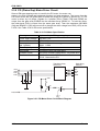
∗ A LOW logic level on the Logic H signal is as follows:
2.0 V or less when the printer is powered off.
3.0 V or more when the printer is powered on.
The receiver provides an impedance equivalent to 7.5 K ohms to ground.
The BUSY signal is HIGH in the following cases:
During data entry
When the input data buffer is full.
While /INIT signal is at low level
During hardware initialization
During the signal /ERROR or PE is LOW or HIGH, respectively.
During the self-test printing mode.
During the default setting mode.
During the adjustment mode.
The /ERROR signal is LOW when one of the following errors has occurred:
Printer hardware error (fatal error)
Paper-out error
The PE signal is HIGH when the following error has occurred:
Paper-out error
1-28
Rev. A
Product Description
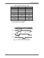
Table 1-24. Data Transmission Timing
Parameter
Minimum
Maximum
tsetup
thold
tstb
tready
tbusy
treply
tack
tnbusy
tnext
1
tt-out *
2
tt-in *
500 ns
500 ns
500 ns
0
500 ns
500 ns
0
0
10 µs
120 ns
200 ns
Note:
1. Rise and fall time for output signals
2. Rise and fall time for input signal
D A T A (n )
D A T A (n + 1 )
D A T A
th o ld
S T O R B E
tn e x t
ts tb
ts e tu p
B U S Y
tre a d y tb u s y
A C K N L G
tr e p ly
ta c k
tn b u s y
Figure 1-14. Data Transmission Timing Chart
Rev. A
1-29
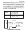
DLQ-3000+
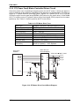
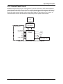
Table 1-25 shows the connector pin assignment and signals for forward channel of the
parallel interface.
Table 1-25. Connector Pin Assignments and Signals (Forward Channel)
Pin No.
Signal Name
Return
GND Pin
I/O
1
/STROBE
19
I
2-9
DATA 1-8
20-27
I
10
/ACKNLG
28
O
11
BUSY
29
O
12
PE
28
O
13
SLCT
28
O
14
/AFXT
30
I
31
/INIT
30
I
32
/ERROR
29
O
36
/SLIN
30
I
18
Logic H
O
35
+5V
O
Chassis GND
17
16,33,19-30
15,34
GND
NC
Description
The strobe pulse. Read-in of data is
performed at the falling edge of this
pulse.
The data 0 to data 7 signals
represent data bits 0 to 7,
respectively. Each signal is at a HIGH
level when data is logical 1 and a
LOW level when data is logical 0.
This signal is a negative pulse
indicating that the printer can again
accept data.
When this signal is at a HIGH level,
the printer is not ready to accept data.
When this signal is at a HIGH level,
the paper empty status is detected.
Always at a HIGH level when the
printer is powered on.
Not used.
The falling edge of a negative pulse
or a LOW signal on this line causes
the printer to initialize. Minimum 50 us
pulse is necessary.
When the printer detects an error, this
signal goes LOW.
Not used.
Pulled up to +5V via 3.9 K-ohm
resistor.
Pulled up to +5V via 3.3 K-ohm
resistor.
Chassis ground.
Signal ground.
Not connected.
Note)
1. */* at the beginning of a signal means active low.
2. The I/O column indicates the direction of the signal as viewed form the printer.
1-30
Rev. A
Product Description
Reverse Channel
Transmission mode
IEEE-1284 nibble mode
Adaptable connector
Same as for the forward channel
Synchronization
Refer to the IEEE-1284 specification
Handshaking
Refer to the IEEE-1284 specification
Data transmission timing
Refer to the IEEE-1284 specification
Signal level
IEEE-1284 level 1 device
See the forward channel.
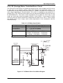
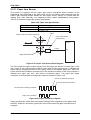
Table 1-26 shows the connector pin assignment and signals for reverse channel of the
parallel interface.
Table 1-26. Connector Pin Assignment and Signals (Reverse Channel)
Pin No.
1
Signal Name
HostClk
Return
GND Pin
I/O
Description
19
I
20-27
I
Clock signal from the host computer.
These signals represent parallel data
on bits 2 to 9. Each signal is High
when the data is logical 1 and LOW
when the data is logical 0.
Clock signal from the printer
Busy signal from the printer.
Data bit 3 or 7 in reverse channel.
Acknowledge request signal.
Data bit 2 or 6 in reverse channel.
X flag signal.
Data bit 1 or 5 in reverse channel.
2-9
DATA 1-8
10
PtrClk
PtrBusy /
Data bit 3,7
AckDatareq /
Data Bit 2,6
28
O
29
O
28
O
28
O
30
30
I
I
29
O
36
Xflag/Data bit
1,5
HostBusy
/INIT
/Data Avail /
Data bit 0,4
1284-Active
30
I
18
Logic-H
O
35
+5V
O
17
Chassis GND
Busy signal from the host computer
Not used
Data available signal.
Data bit 0 or 4 in reverse channel.
1284 active signal.
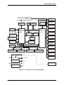
Pulled up to +5V via 3.9 K-ohm
resistor.
Pulled up to +5V via 3.3 K-ohm
resistor.
Chassis ground for the printer.
GND
Signal ground.
NC
Not connected.
11
12
13
14
31
32
16,33,
19-30
15,34
Note)
1. */* at the beginning of a signal means active low.
2. The I/O column indicates the direction of the signal as viewed form the printer.
Rev. A
1-31
DLQ-3000+
Extensibility Request
The printer responds affirmatively when the extensibility request values are 00H or 04H,
as follows:
00H Request nibble mode reverse channel transfer.
04H Request device ID using nibble mode rev channel transfer
Device ID
The printer sends following device ID string upon request:
[00H] [3DH]
MFG EPSON;
CMD ESCPL2, PRPXL24, BDC;
MDL DLQ-3000+;
CLS PRINTER;
1-32
Rev. A
Product Description
1.4.2 Serial Interface
Synchronization
Asynchronous
Signal level
EIA-232D
MARK (logical 1):
SPACE (logical):
-3 V to -25 V
+3 V to +25 V
Word format
Start bit:
Data bit:
Parity bit:
Stop bit:
Baud rate
300, 600, 1200, 2400, 4800, 9600 or 19200 bps
1 bit
8 bit
Odd, Even or Non
1 bit
Handshaking
DTR signal and XON/XOFF
DTR = MARK, XOFF:
Indicates that the printer cannot receive data.
DTR = SPACE, XON:
Indicates that the printer is ready to receive data.
The DTR signal is MARK and XOFF code (DC3, 13H) is transmitted when the rest of
the input buffer becomes 256 byte. The DTR signal is SPACE and XON code (DC1,
11H) is transmitted when the rest of the input buffer becomes 256 byte.
Error handling
Parity error is detected only.
(Overrun error and framing error are ignored.)
Connector
25-pin sub-miniature D-shell connector. (female)
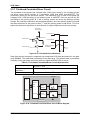
Table 1-27. Connector Pin Assignment for Serial Interface
Pin No. Signal Name
1
2
3
Function Description
Out
In
Chassis GND
Transmits data
Receives data
Request to send. Always SPACE level
4
RTS
Out
when the printer is powered on. Pulled
up to +12 V via 4.7 L ohm resistor.
7
Signal GND
Signal GND
11
REV
Out
Connected directly to the DTR signal.
20
DTR
Out
Data terminal ready
others
NC
Not used. Not connected.
Note: In and Out refers to the direction of the signal flow from the printer’s point of
view.
Rev. A
Chassis GND
TXD
RXD
I/O
1-33
DLQ-3000+
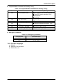
1.4.3 Optional Interface
The EPSON DLQ-3000+ supports an optional Type-B interface (Level 2) with the following
characteristics.
Reply message
Table 1-28. Reply Message
Reply message
ESC/P2
Main-type
Product name
Emulation type
Entity type
IBM 2391 Plus
MT24p, PW136cl10cpi, PRG(W0xxxx)rev
DLQ-3000+
ESCPL2, PRPXL24, BDC
EPSONLQ2
EPSONPRPXL24
Reply for optional command
Table 1-29. Reply for Option Command
Option command No.
command name
00h
01h
02h
03h
04h
05h
06h
No Operation
Start Hard Ware Reset
Start Soft Ware Reset
Send Main System Type
Send Name Data
Inquire Name Data
Send Product Name
Send Soft Ware Emulation
Type
Complete Buffered Data
Stop Procedure
Return Buffered Data
Send Entity Type
Send Status
Quit Procedure
Inquire ASCII Message
Send ASCII Message
(Reserved)
Inquire Emergency Message
Send Emergency Reply
(Reserved)
07h
08h
09h
0Ah
0Bh
0Ch
0Dh
0Eh
0Fh
10h - 13h
14h
15h
16h - 1Fh
1-34
Reply-A
Accept
Reject
Accept
Reject
Accept
Accept
Accept
Accept
Reject
Reject
Accept
Accept
Reject
Reject
Accept
Unknown
Accept
Accept
Unknown
Reply-B
Execute OK
Execute OK
Execute OK
Execute OK
Execute OK
Execute OK
Execute OK
Execute OK
Execute OK
Execute OK
Execute OK
Rev. A
Product Description
Supported Main Command and Sending Timing
Table 1-30. Supported Main Command and Sending Timing
Main Command
Command name
01h
Start Software Reset
02h
Send option type
04h
Send Name Data
Inquire Software Emulation
Name
Inquire ASCII Message
Inquire Emergency Reply
Send Emergency Message
07h
0Eh
14h
15h
Sending Timing
/INIT signal on the standard parallel I/F
Type-B I/F option command : 01h
Panel Reset
Cold Start
Deciding the level of type-B I/F after
power on.
Type-B I/F option command : 05h
Changing software Emulation Type
Writing to DBIN register
Reply for Emergency command
Receive Emergency Command
Emergency Command
Table 1-31. Emergency Command
Command No.
Command name
0x00
0x01
Get device IC
Get all status
1.4.4 Printer language
ESC/P2
IBM 2391 Plus emulation
EPSON Remote
Rev. A
1-35
DLQ-3000+
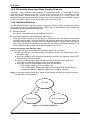
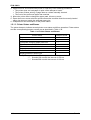
1.4.5 Prevention Hosts from Data Transfer Time-out
Generally, hosts abandon data transfer to peripherals when a peripheral is BUSY
continuously for dozens of seconds. To prevent this kind of time-out, the printer receives
data very slowly, several bytes par minute, even the printer is in a busy state. This
slowdown starts when the remainder of input buffer drops under several hundreds of bytes.
Finally, the printer is BUSY continuously when the input buffer is full.
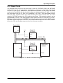
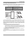
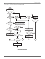
1.4.6 Interface Selection
The EPSON DLQ-3000+ has three types of interfaces: Parallel, Serial, and optional Type-B.
Each interface can be selected manually by SelecType or automatically. Both modes are
selected thorough the default setting mode.
Manual selection
One of the 3 interfaces can be selected by SelecType.
Automatic selection mode (Enabled by SelecType)
When the printer is powered on, the printer is initialized to the idle state scanning which
interface receives data. Then the interface that receives data first is selected. When the
host stops data transfer and the printer is in stand-by state for the seconds specified by
SelecType, the printer is returned to the idle state. As long as the host sends data or the
printer interface is busy state, the selected interface is left as it is.
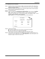
Interface selection and interface state
Interface selection and the corresponding interface states are as follows:
When an interface other than parallel interface is selected, the interface goes into
the BUSY state.
When an interface other than serial interface is selected, the interface sends XOFF
and sets the DTR signal MARK.
When an interface other than optional interface is selected, the printer sets
“OFFLINE” bit of MNSTS register to the optional interface.
When the printer is initialized and returned to the idle state:
• The parallel interface goes into ready state.
• The serial interface sends XON and sets the DTR SPACE and the printer
resets OFFLINE bit of MNSTS register to the optional interface.
Note: An interrupt signal such as /INIT signal on the parallel interface is not effective while
that interface is not selected.
Idle State
Selected State
Non-selected State
Figure 1-15. Interface Selection
1-36
Rev. A
Product Description
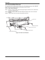
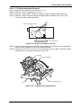
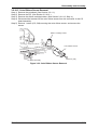
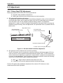
1.5 Operation
This section describes the function of each button on the control panel and LED printer
status indicators.
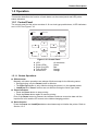
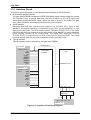
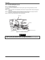
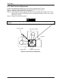
1.5.1 Control Panel
The control panel for this printer consists of 10 non-lock type push buttons, 4 LED indicators
and 1 LCD. See Figure 1-16.
P o w e r
P a p e r O u t
1 6 -c h a ra c te r L C D
S e le c T y p e
P a p e r s e le c t
T e a r O ff
L F /F F
F o n t
P itc h
L o a d /E je c t
P a u s e
-----R e s e t-----
Figure 1-16. Control Panel
LCD:
Power LEDs:
Paper Out LED:
Tear-off LED:
Pause LED:
16 characters
Green
Red
Orange
Orange
1.5.1.1 Button Operations
Effectiveness
Basically, all button operations are always effective except for the following cases.
• During printing, only the Pause button is effective.
• The SelecType button is only effective during the printer is in the standby status.
• Load/Eject and “Pause” buttons are not effective during the SelecType mode.
Pause functions
• Press the Pause button to stop printing.
• Press the Pause button again to resume printing.
Even if the Pause button is pressed, the interface continues to receive data until the
input buffer is full and the CR moves to the ribbon changing position.
Reset function
Press the Pause and Load/Eject buttons simultaneously to initialize the printer. Refer to
Section 1.5.5.
Rev. A
1-37
DLQ-3000+
Paper feed function
Table 1-32 shows the button operations and the corresponding paper feed functions.
Table 1-32. Paper Feed Functions
Operations
Function
Paper loaded
Paper out
Friction feed
Line feed
Load a sheet *².
Tractor feed
Line feed *¹
Load continuous paper
Friction feed
Form feed
Load a sheet *².
Tractor feed
Form feed *¹
Load continuous paper
Friction feed
Eject
Load a sheet *².
Tractor feed
Paper park*¹
Load continuous paper
Friction feed
Micro feed (forward)
—
Tractor feed
Micro feed (forward) *³
—
Friction feed
Micro feed (backward)
—
Press ↑.
Tractor feed
Micro feed (backward)*³
—
Insert a sheet to the manual
Load the inserted sheet.
—
insertion slot. (Friction feed)
*².
Notes)
1. When the printer is in the tear-off state, these functions are performed after returning
from the tear-off position.
2. Once a sheet is manually inserted, the printer enters manual insertion mode. While the
mode is active, even if data is remaining in the buffer, the printer goes into a paper-out
error state at each end of a sheet and waits for the next sheet to be inserted. CSF
insertion is enabled again by loading sheets into the CSF or by initializing the printer.
3. ↓ and ↑ buttons are used as described below:
• Pressing the button continuously feeds paper forward*/backward* with a increment
of 1/180 inch.
• Pressing the button continuously feeds paper forward*/backward* slowly.
• When the printer is in the tear-off state, these buttons are used to adjust tear-off
position. The adjusted position is stored in the EEPROM.
* To feed forward or backward means toward the front or rear of the printer,
respectively.
Press LF/FF
shortly.
Press LF/FF for
a few seconds.
Press.
Load/Eject
Press ↓.
Tear -off function
The printer has 2 types of tear-off functions; manual tear-off and auto tear-off. The
manual tea-off is performed by pressing the Tear Off button . The auto tear-off is
enabled by SelecType. These functions are same as for the conventional EPSON
printers.
Paper select function
Press the Paper Select button to select one of the following paper memory numbers.
• 0:
All cases
• a(9):
When the printer has the special paper information.
Note: The Paper Select button is only effective without any paper set.
1-38
Rev. A
Product Description
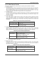
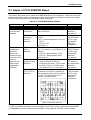
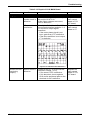
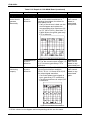
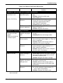
1.5.1.2 Printer Status and LCD/LED Indicator Conditions
Table 1-33 shows the printer status and When the printer is in more than one status, the
printer indicates the prime status. If they have the same priority, the status occurs first is
indicated. The priority in the first column means that the status with the lower numbers have
higher priority.
Table 1-33. Printer Status and LCD/LED Indicator Conditions
Priority
Printer State
1
2
3
1
Fatal error *
Program reload mode
Cover open error
4
5
Release lever operation
2
error *
Paper jam error
6
Paper out error *
7
Incomplete changing
4
paper path error *
8
Paper Out
LED
Pause
Please turn off
Program Mode
Cover Open
Blinks
Off
6
On/Off *
Blinks
Off
On
Put Lever Back
Blinks
On
Paper Jam
Blinks
On
Paper Out
On
On
Wrong Paper Path
Off
On
Paper size error *
Wrong Paper Size
Off
On
9
Eject error
Pull Paper Out
Blinks
On
10
Printhead is overheated.
Please Wait
Off
Blinks
11
11
12
Entry to SelecType 1
Entry to SelecType 2
Tear-off
SelecType 1
SelecType 2
Cut the paper
Off
Off
Off
Off
Off
On/Off
6
*
Data in Buffer
Off
On
13
3
5
Data is in buffer but the
printer is paused
Pause
Bi-D adjustment
Hex dump mode
Ordinary printing
Test printing
Setting printing
Standby
LCD message
Tear-Off
Blinks
Off
On/Off
6
*
On/Off
6
*
On/Off
6
*
On/Off
6
*
On/Off
6
*
On/Off
6
*
On/Off
6
*
On/Off
6
*
Off
Off
On
Off
14
Pause : #0
Off
On
Off
15
Bi-d adjustment
Off
Off
Off
15
Hex dump
Off
Off
Off
15
Printing : #0
Off
Off
Off
15
Test Printing
Off
Off
Off
15
Setting Printing
Off
Off
Off
16
Ready : #0
Off
Off
Off
Notes)
1. Fatal error occurs when the printer is under any of the following conditions:
• Power supply voltage is at an abnormal level.
• The printhead temperature is abnormal.
• Carriage does not move normally.
• Platen gap does not move normally.
• An error occurs while executing EEPROM commands or program reload mode.
• The printer control circuit does not work correctly.
2. This error occurs when the friction lever is not set to the appropriate position.
Rev. A
1-39
DLQ-3000+
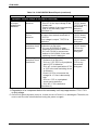
3. Paper-out error occurs when the printer is under any of the following conditions:
• The printer does not load paper in spite of the attempt to load it.
• The printer finishes printing 1-page data on a sheet manually inserted.
• The end of the continuous paper has reached.
4. When the printer fails to change the paper path, this error occurs.
5. Paper size error occurs when the printer senses the condition that the currently loaded
paper size does not match the selected paper size.
6. It depends on the combination of the printer status.
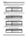
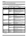
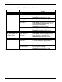
1.5.1.3 Printer Status and Buzzer
The printer beeps to indicate several printer error status and failure operation. Printer status
and the corresponding beeper sounds are as described in Table 1-34.
Table 1-34. Printer Status and Buzzer
Printer status
Beeper sound
Paper out error has occurred.
–––
Paper size error has occurred.
–––
Incomplete changing paper path error
–––
Eject error has occurred.
–––
Release lever operation error has occurred.
—————
Paper jam error has occurred.
—————
Fatal error has occurred.
—————
Illegal operation in SelecType
–
Notes) The symbols “–“ and “—“ represent how a beep sounds.
“–“: Sounds 100 ms with the interval of 100 ms.
“—“: Sounds 500 ms with the interval of 100 ms.
1-40
Rev. A
Product Description
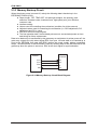
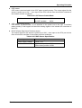
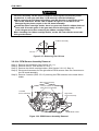
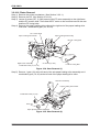
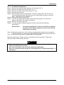
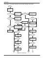
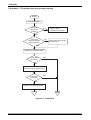
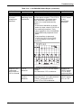
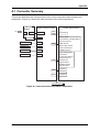
1.5.2 SelecType
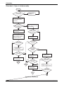
This printer provides SelecType function to change default settings.
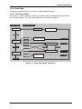
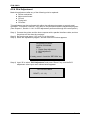
1.5.2.1 SelecType Phase
See Figure 1-17 which shows the SelecType phase transitions. Boxes show printer states
or SelecType phases. The boxes with shadow involves button operations.
P r in te r S ta te
S e le c T y p e P h a s e
S e le c T y p e
in itn a liz a tio n *
S ta n d b y s ta te
D a ta s a v e p h a s e
S e le c T y p e
S e le c T y p e
S e le c T y p e 1 p h a s e
E n try to
S e le c T y p e 1
F O N T
F o n t s e le c tio n p h a s e
S e le c T y p e
P IT C H
S e le c T y p e
F O N T
F O N T
E n try to
S e le c T y p e 2
P IT C H
P itc h s e le c tio n p h a s e
P IT C H
S e le c T y p e 2 p h a s e
S e le c T y p e
S e le c T y p e
S e le c T y p e
Figure 1-17. SelecType Phase Transitions
Rev. A
1-41
DLQ-3000+
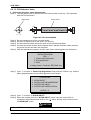
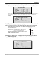
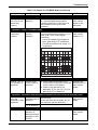
1.5.2.2 SelecType Operation
SelecType 1 and 2 operations
Step 1. Selecting the feature
When the SelecType 1 or 2 starts, the first feature appears on the LCD. Scroll the
features by pressing the “↑” (next) or “↓” (previous) button until the desired feature
appears. Then press the “→” (enter) button, and the option menu for the selected
feature is displayed.
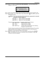
Step 2. Keeping/Changing the option
The current option marked with “*” for the menu appears. To keep the option as it is,
press the “←” button (escape) to return to the feature menu. To change the option,
press the “↑” (next) or “↓” (previous) button to scroll the option menu. Then press the
“→” (enter) button to fix the desired option. If the “Other” is selected, another option
menu appears. In this case, select the desirable option in the above mentioned way.
Step 3. Return to the previous menu
Press the “←” button (escape) to return to the previous menu. Pressing the button
several times to return to the SelecType 1 or 2 entry state.
Step 4. Exit
Press the “SelecType” button to exit the SelecType phase. With this operation, new
settings are automatically stored in the EEPROM and are effective until they are
changed again. This process is automatically followed by the SelecType initialization
phase and the printer returns to the stand-by status.
[Initializing all settings to the standard]
Select “Standard Setting” in the SelecType 2 menu. The message “Ready?” is
displayed. Then perform one of the followings:
To execute the initialization:
Press the “→” (enter) button. (All settings are reset to the standard and the printer
returns to the feature menu.
To return to the feature menu without executing the initialization
Press the “←” button (escape).
Press the “SelecType” button to exit the SelecType mode.
Font and Pitch Select Operation
Step 1. Displaying the current selection for the font/pitch
When the printer enters the Font/Pitch phase, the current option marked with “*”
appears.
Step 2. Changing the font/pitch
Press the “↑” (next) or “↓” (previous) button until the desired font/pitch appears.
Then press the “→” (enter) button to fix the selection. The selected font/pitch is
marked with “*” as the result.
Step 3. Exit
Press the “SelecType” button to exit the Font/Pitch phase.
1-42
Rev. A
Product Description
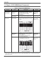
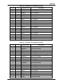
1.5.2.3 SelecType Option
Table 1-35 and Table 1-36 show the options available for the SelecType 1 and SelecType
2, Font and Pitch, respectively.
Table 1-35. SelecType 1 Option
Menu
T-margin Tractor
T-Margin Manual R
T-Margin Manual L
T-Margin CSF
Character Table
Page Tractor
Page CSF
Option
*8.5 mm
from 4.2 mm to 8.5 mm + 25.4 mm
*8.5 mm
from 0 mm to 8.5 mm + 25.4 mm
*8.5 mm
from 0 mm to 8.5 mm + 25.4 mm
*8.5 mm
from 0 mm to 8.5 mm + 25.4 mm
NLSP version
*PC437
PC437 Greek
PC850
PC852,
PC853
PC855
PC857
PC864
PC866
PC869
ISO Latin 1T
Code MJK Bulgaria Estonia
ISO 8859-7
MAZOWIA
PC774
ISO 8859-2
PC866LAT
PCAPTEC
PC 708
PC720
PCAR864
PC 860
PC865
PC861
USA – KOREA
Standard version
*PC437
PC850
PC860
PC861
PC863
PC865
Abicomp BRASCII ISO Latin 1
Roman 8 U.S.A – Korea
*11 inch
12 inch
8.5 inch
70/6 inch (A4)
Other (See the right column.)
*A4
Letter
Other (See the right column.)
*0.000 inch
From 0 to 1 inch
Line spacing
*1/6 inch
1/8 inch
*0 columns
Left-Margin
From 0 to 80 columns
*136 columns
Right-Margin
From 1 to 136 columns
*Bi-directional
Uni-directional
Print Direction
Auto
Note: The current options are marked with “*”.
B-Margin Tractor
Rev. A
Note
Increment : 0.14 mm (1/180”)
Increment : 0.14 mm (1/180”)
Increment : 0.14 mm (1/180”)
Increment : 0.14 mm (1/180”)
Option for “Other”:
xxx lines (from 24 to 132
lines at 1/6 line spacing)
Option for “Other”:
xxx lines (from 24 to *132
lines)
Increment: 1/180 inch
At 1/6 inch spacing
1-43
DLQ-3000+
Table 1-36. Options for SelecType 2, Font and Pitch
Menu
SelecType 2
Language
Paper Type
Overlapping Form
Intensity Mode
Software
Auto CR (IBM)
A.G.M. (IBM)
Interface
I/F Time-out
Input Buffer
Baud Rate
Parity
Auto Tear-off
Auto LF
0 Slash
Buzzer
Standard Setting
Font
*Roman
Sans Serif
Script
OCR B
Script C
Roman T
H-Speed Draft
Pitch
Option
*English
German
Spanish
*Normal
Envelopes
*Off
*Normal
Notes
French
Italian
Portuguese
Cards
On
Dark
*ESC/P2
IBM 2391 Plus
*Off
On
*Off
On
*Auto Selection
Parallel
RS-232C
Option Slot
*10 sec.
From 1 to 255 seconds
*On
Off
300 BPS
600 BPS
1200 BPS
2400 BPS
4800 BPS
9600 BPS
*19200 BPS
*None
Even
Odd
*Off
On
*Off
On
*Off
On
*On
Off
Ready?
Courier
Orator
Sans Serif H
For cut sheet only
For continuous paper only
Use the copy mode only
when the depth of multipart form printing is not
enough.
For IBM 2391 Plus emulation
For IBM 2391 Plus emulation
Prestige
Orator S
Draft
*10 cpi
12 cpi
15 cpi
17 cpi
20 cpi
Proportional
Note: The current options are marked with “*”.
1-44
Rev. A
Product Description
1.5.3 Functions at Power On
This printer has the following 7 service modes. To enter each mode, press specified button
(buttons) while holding down the Power switch.
Test Printing
• Button
• Result
• Exit
• Interface state
LF/FF button with the power switch On.
LQ mode:
Load/Eject button with the power switch On.
Draft mode:
Alphanumeric characters are printed continuously.
Press the Pause button and turn the printer Off.
All interfaces keep a busy state during the test printing.
Hex Dump Mode
• Buttons
• Result
(period) is
• Exit
LF/FF and Load/Eject buttons with the power switch On.
The printer prints the message “Hex Dump” and then starts printing
received data in the both hexadecimal code and corresponding
characters. If corresponding character does not exist, “.”
printed instead.
Press the Pause button to print data remaining in buffer. Then turn
off the printer to exit the mode.
Setting Printing
• Button
• Result
• Exit
printer
• Interface State
SelecType button with the power switch On.
Firmware version and user changeable default setting menu
(SelecType menu) along with their options are printed with the
subtitles in the selected language.
When the printing is complete, the printed sheet or continuous paper
is ejected or fed to the tear-off position, respectively. Then the
returns to the standby status.
All the interfaces keeps a busy state during the printing.
Note: In each mode mentioned above, when the printer fails to load paper, the printer goes
into the Paper-out error status. In this case, insert a sheet and press the Load/Eject
button. (In the Hex Dump mode, the message “Hex Dump” is printed at first. Then the
printer waits for data.)
Bi-D adjustment (Refer to Section 1.5.4.)
• Button
Pause button with the power switch On.
Program Reload Mode (Refer to Section 1.5.5.)
• Buttons
Tear Off, LF/FF, Load/Eject and Pause buttons with the power
switch On.
EEPROM Clear
• Buttons
• Result
SelecType, Paper Select, and Pause buttons with the power switch
On.
Resets the printer to the standard factory setting, which is not always
proper setting for each market.
(This function is used only for emergency.)
Clear the driving line count for ribbon changing timing
• Button
• Result
Rev. A
Paper Select button with the power switch On.
Clears the value for the driving line count stored in the EEPROM.
1-45
DLQ-3000+
1.5.4 Bi-D Adjustment Mode
This printer has the Bi-D adjustment mode which enables users to align vertical lines. Refer
to Table 1-37 and Figure 1-18.
Table 1-37. Bi-D Adjustment Item
Items
Order
Draft mode
Bit Image (ESC ∗ 26H) mode
LQ mode
1
2
3
S ta rt
T u r n th e p r in te r o n w h ile
h o ld in g d o w n " P a u s e " b u tto n .
T h e p r in te r p r in ts th e g u id e fo r
B i- D a d ju s tm e n t a n d th e p a tte r n
p r in t fo r th e d r a ft m o d e .
P r e s s " " o r " " b u tto n u n til th e
L C D in d ic a te s th e n u m b e r fo r th e
m o s t c lo s e ly a lig n e d p a tte r n .
: N e x t
: P r e v io u s
: E n te r
F ix th e s e le c te d n u m b e r b y
p r e s s in g "
" b u tto n , a n d th e
p r in te r p r in ts th e n e x t p a tte r n p r in t.
A r e a ll th e a d ju s tm e n ts
m a d e ?
N o
Y e s
T u r n th e p r in te r o ff.
E n d
Figure 1-18. Bi-D Adjustment Flowchart
1.5.5 Program Reload Mode
The printer has a 512-K byte Flash-EEPROM as a printer control software and a boot-strap
program storage. This Flash-EEPROM can erase all the data in itself at once electrically
and reprogram. Using this mode, the printer control software can be changed completely.
Refer to Chapter 3 for details.
1-46
Rev. A
Product Description
1.5.6 Initialization
1.5.6.1 Printer Initialization
This printer has 5 initialization types: Power-on initialization, Operator initialization,
Initialization by the control panel operation, Software initialization and SelecType
initialization.
Power-on Initialization
Triggers
• Turning on the printer
• Cold reset command (Remote RS command)
Actions performed
• Initializes the printer mechanism.
• Clears input data buffer.
• Clears download character set.
• Clears print buffer.
• Sets default values.
Operator Initialization
Trigger
• The printer recognizes the /INIT signal (negative pulse) of parallel interface.
Actions Performed
• Clears input data buffer.
• Clears download character set.
• Clears print buffer.
• Sets default values.
Initialization by the control panel operation
Trigger
• Pressing the Pause and Load/Eject buttons for 3 seconds.
Actions performed
• Clears input data buffer.
• Clears print buffer.
• Sets default values.
Software Initialization
Trigger
• ESC @ commend
Actions Performed
• Clears print buffer.
• Sets default values.
SelecType Initialization
Trigger
• Exiting the SelecType mode
Actions Performed
• The printer settings are reset to the default except the download definition is
not cleared.
• The printer is put into the standby status.
Rev. A
1-47
DLQ-3000+
1.5.6.2 Initialize Defaults to the Standard
The use changeable defaults can be initialized to the standard settings by SelecType. The
standard settings are shown in Table 1-38.
Table 1-38. Standard Settings
Items
Font
Pitch
Character Table
Page Length
Line Spacing
Top Margin
Standard settings
Tractor
CSF
Tractor
Manual Rear
Manual Front
CSF
Tractor
Bottom Margin
Left Margin
Right Margin
Print Direction
Message Language
Software
Interface
Interface Auto Selection Time-out
Input buffer
Serial interface
Baud Rate
Parity
Auto Tear-off
Auto LF
Auto CR (IBM 2391 PLUS)
AGM (IBM 2391 PLUS)
Over-lapping Forms
Paper Type (Cut sheet)
Intensity Mode
0 slash
Buzzer
1-48
Roman
10 cpi
PC437
11 inch
132 lines
1/6 inch
8.5 mm
8.5 mm
8.5 mm
8.5 mm
0.0 mm
0 column
136 columns
Bi-directional
English
ESC/P2
Auto Selection
10 seconds
ON
19200 bps
None
Off
Off
Off
Off
Off
Normal
Normal
Off
On
Rev. A
Product Description
1.6 Main Components
This printer is composed of the following components:
Printer mechanism
Main control board
PSB/PSE board
Control panel
Housings
C210MAIN
C124 PSB/PSE
1.6.1 C210MAIN Board
The C210MAIN consists of the followings:
CPU (H8/3033
Gate array (E05B46)
CG-ROM
DRAM
EEPROM
Drivers
Flash-ROM/P-ROM for the program ROM
S L A 7 0 2 6 M
( C R M o to r D r iv e r )
S D C 0 3 -V 1
( P G M o to r D r iv e r )
S L A 5 0 0 1
( P r in th e a d D r iv e r )
S L A 7 0 2 4 M
( P F M o to r D r iv e r )
M P 5 3 0 2
( R ib b o n M o to r D r iv e r )
C G -R O M
F lu s h R O M
(P R O G R A M )
D R A M
2 S A 1 4 5 1
( P r in th e a d D r iv e r )
E 0 5 A 8 8 (G A T E A R R A Y )
H 8 /3 0 0 3 (C P U )
E E P R O M
Figure 1-19. C210MAIN Board Component Layout
Rev. A
1-49
DLQ-3000+
1.6.2 C124PSB/PSE Board
The electoral circuit board of this printer consists of 2 switching regulator circuits.
S w itc h in g F E T
F u s e
T ra n s fo rm e r (T 1 0 1 )
T L 4 9 4
( R e g u la to r )
F ilte r
T ra n s fo rm e r (T 2 0 1 )
Figure 1-20. C124PSB/PSE Board Component Layout
1.6.3 Printer Mechanism
The printer mechanism of this printer is composed of the followings:
CR motor
Ribbon motor
2 cooling fans
CR mechanism
PF motor
PG motor
Paper feed mechanism
Figure 1-21. Printer Mechanism
1-50
Rev. A
Product Description
1.6.4 Housing
This printer is composed of the following housings:
Bottom frame assembly Lower housing assembly
Upper housing assembly Rear shield cover
Printer cover assembly Rear cover
Upper connector cover
R e a r S h ie ld C o v e r
U p p e r H o u s in g A s s e m b ly
U p p e r C o n n e c to r C o v e r
P r in te r C o v e r A s s e m b ly
L o w e r H o u s in g A s s e m b ly
R e a r C o v e r
B o tto m
F r a m e A s s e m b ly
Figure 1-22. Printer Housings
Rev. A
1-51
Chapter 2
Operating Principle
2.1 Printer Mechanism Operating Principles............................................. 2-1
2.1.1 Printing Mechanism ...................................................................... 2-1
2.1.2 CR (Carriage) Mechanism ............................................................ 2-3
2.1.3 PG (Platen Gap) Adjustment Mechanism.................................... 2-4
2.1.4 Ribbon Feed/Ribbon Shift Mechanism........................................ 2-6
2.1.4.1 Ribbon Feed Mechanism..................................................... 2-7
2.1.4.2 Ribbon Shift Mechanism...................................................... 2-7
2.1.5 Paper Feed Mechanism ................................................................ 2-9
2.1.5.1 Core of the Paper Feed Mechanism.................................... 2-9
2.1.5.2 Paper Feed Sensor Mechanism ........................................ 2-10
2.1.5.3 Release Mechanism .......................................................... 2-12
2.2 Circuit Operating Principles................................................................ 2-13
2.2.1 Power Supply Voltage................................................................. 2-13
2.2.2 Power Supply Circuit Operation ................................................ 2-14
2.3 Controller Circuit.................................................................................. 2-15
2.3.1 Interface Circuit ........................................................................... 2-18
2.3.2 Reset Circuit ................................................................................ 2-19
2.3.3 Memory Back-up Circuit ............................................................. 2-20
2.3.4 Ribbon Motor Controller/Driver Circuit ..................................... 2-21
2.3.5 PF (Paper Feed) Motor Controller/Driver Circuit...................... 2-22
2.3.6 CR (Carriage) Motor Controller/Driver Circuit .......................... 2-23
2.3.6.1 Bi-D Adjustment Function.................................................. 2-25
2.3.6.2 Interlock Function .............................................................. 2-25
2.3.7 Printhead Controller/Driver Circuit............................................ 2-26
2.3.8 Control Panel Circuit................................................................... 2-27
2.3.9 PG (Platen Gap) Motor Driver Circuit ........................................ 2-28
2.3.10 Paper Thickness Detecting Circuit .......................................... 2-29
2.3.11 Paper Jam Sensor ..................................................................... 2-30
2.3.12 Other Sensor Circuits ............................................................... 2-31
Operating Principles
2.1 Printer Mechanism Operating Principles
This chapter describes the operating principles of the printer mechanism (M-5P60).
2.1.1 Printing Mechanism
Printhead
The printing mechanism of this printer is composed of the 24-pin impact dot printhead
and a ribbon mask. The printhead has 12 pin wires in each of 2 rows, which are aligned
in an rhombic layout. (See Figure 1-2 in Chapter 1.) Each wire has its own drive coil.
A c tu a tin g P la te
S to p p e r
A c tu a tin g S p r in g
W ir e R e s e ttin g S p r in g
H e a d D r iv in g C o il
Iro n C o re
P a p e r
D o t W ir e
In k R ib b o n
R ib b o n M a s k
P la te n
Printing process
Figure 2-1. Structure of the printhead
1. The printing signal transmitted from controller circuit to the head driver circuit is
converted into the head drive voltage, which energizes a corresponding coil. The
energized coil then magnetizes the iron core.
2. The magnetized iron core draws the actuating plate which joins to the dot wire. This
movement rushes the wire toward the platen.
3. When the dot causes impact to the platen, it presses the ribbon to the paper, where a
dot prints.
4. When the coil energizing is terminated, the iron core, losing magnetic force, is
returned to the standby position by the bounce of the platen and tension of the
actuating spring.
The printing mechanism has an integrated thermistor to detect head temperatures. The
detected temperature is converted into an electrical signal and fed back to the controller
circuit. This information as well as paper thickness is used as a basis for determining
printhead driving mode to ensure high printing quality. It is particularly important to keep the
head temperature at a proper level constantly to minimize burning and deterioration of the
dot wires in the printhead, which are caused by the rise in the head temperatures due to
continuous printing. When the head temperature is below the specified level, the
appropriate driving mode is selected based on the detected temperature to keep the wires
respondent. (Refer to Section 1.3.1 in Chapter 1.) See Table 2-1 in Page 2-2 for the
printhead specification.
Rev. A
2-1
DLQ-3000+
Table 2-1. Printhead Specification
Item
Printing method
Number of wires
Wire diameter
Head life
Weight
Coil resistance
Response period
Drive voltage
Driving condition
Environmental condition
Printhead drive method
2-2
Description
Impact dot printing
24 wires (14 wires on each of 2 rows in an rhombic
layout)
0.20 mm
Monochrome fabric ribbon: 200 million strokes / wire
Color ribbon:
100 million strokes / wire
180 g
8.19 ± 0.5 Ω (at 25° C)
Normal mode: 462 µs
31.5 to 38.5 V
• Normal drive copy mode (when multi-part form or thick
paper is used.)
• High duty condition (head temperature is high)
• Cold mode (head temperature is low.)
Temperature: 5 to 55° C
Humidity:
10 to 85 %
Flywheel type
Rev. A
Operating Principles
2.1.2 CR (Carriage) Mechanism
The CR mechanism consists of the CR movement mechanism, external cooling fan, and
platen gap adjustment mechanism.
CR movement mechanism
The CR is supported by 2 CR guide shafts by its high and low ends. The stepping motor
used for the CR motor enables the CR to move to any positions. The motor also sends
torque to the timing belt pulley to drive the timing belt. The timing belt with one of the
edges fixed to the head carriage moves the head carriage along the carriage guide shaft
from right to left or vice versa according to the direction the CR motor rotates. Since the
length of the belt is affected by the change in temperature, belt tension spring is
attached to keep the belt with a constant tension. The HP sensor (Home Position sensor)
is located at the reference position (on the right side as seen from the front) in the printer
mechanism. Photo-coupler system used for the sensor detects the CR when the flag of
the CR crosses emission. It is only operated when the printer is turned on, and once it is
detected, CR movement is put under the open-loop control system. After the controller
circuit determines where to move the CR according to the received data, it converts the
distance to the position into the corresponding phase change pulse and outputs it to the
CR motor. If the CR home position is detected during printing or the printer initialization, it
indicates the status that the printer fails to detect the home position at a correct position
and an error occurs as a result. CR speed is controlled by the CR motor drive frequency
which depends on the printing data.
Belt Tension Spring
CR
Timing Belt
Flag
CR HP Sensor
Bushing
Timing Belt Pulley
Platen
Printhead
Cooling Air
External Cooling Fan
External cooling fans
Figure 2-2. CR Mechanism
This printer is equipped with 2 cooling fans. One, located at the left bottom of the printer,
eliminates excess heat from the circuit boards. The other one is externally attached to
the right side of the printer mechanism to blow the air directly to remove excess heat
from the printhead.
Table 2-2. External Cooling Fan Unit Specification
Type
Power supply voltage
Consumption current
Rotating speed
Rev. A
DC brush-less motor (ball bearing built in)
35 VDC ± 10 %
0.07 A or less
3800 rpm or more
2-3
DLQ-3000+
2.1.3 PG (Platen Gap) Adjustment Mechanism
PG adjustment is made manually and automatically. In the manual PG adjustment mode,
the proper PG is originally set for the paper to be loaded by manually operating the PG
adjust lever located at the left front of the printer. On the other hand, the automatic PG
adjustment function lets the printer automatically measure the paper thickness and set the
proper PG for the thickness. This mode is activated by setting the PG adjust lever to the
automatic side. Figure 2-3 shows the PG adjustment mechanism.
Slit Disc
Paper Thickness Sensor
PG Motor
Pinion Gear
CR Guide Shaft
Combination Gear
Printhead (CR Unit)
Sector Gear
Ink Ribbon
Ribbon Mask
Paper
PGHP Sensor
Platen
Figure 2-3. PG adjustment Mechanism
The PG adjustment mechanism located at the left top of the printer mechanism unit consists
of the PG motor, CR guide shaft, sectorial gear, combination gear, PG home position
sensor, and paper thickness sensor., After the PG is determined by the controller circuit
according to the paper thickness, the PG motor rotates corresponding amount. The torque
from the PG motor is transmitted via the motor pinion gear, combination gear and sectorial
gear to the CR guide shaft. Since the shaft is eccentric, the CR on the shaft moves from or
toward the platen as the shaft moves, depending on the direction the motor rotates. Seeing
from the left side of the printer mechanism, the clockwise or counterclockwise rotation of the
CR guide shaft narrows or widens the PG, respectively. The PG home position is detected
when the sectorial gear pushes the actuator on the PG home position sensor.
2-4
Rev. A
Operating Principles
Manual PG adjustment function
This function allows the user to set the proper PG manually by setting the PG adjust
lever to one of the steps from -1 to 9. The selected step is converted into 4-bit data using
adjustment switches and the data is transferred to the controller circuit, where the PG is
determined based on the information.
Table 2-3. PG and PG Adjust Switch
PG lever
Steps
Adjust switch condition
#1
#2
#3
#4
{
{
{
{
{
{
{
Corresponding paper
Thickness (PT)
PG width
(mm)
-1
0.06=<PT<=0.11
0.35
−
0
0.06=<PT<=0.11
0.39
−
−
1
0.11<PT<=0.15
0.43
−
−
2
0.15<PT<=0.19
0.46
−
−
−
3
0.19<PT<=0.25
0.50
−
4
0.25<PT<=0.30
0.55
−
−
5
0.30<PT<=0.36
0.61
−
−
6
0.36<PT<=0.42
0.67
−
−
−
7
0.42<PT<=0.46
0.71
−
−
8
0.46<PT<=0.49
0.74
−
−
−
9
0.49<PT<=0.53
0.78
−
−
−
Automatic
0.06=<PT<=0.53
Note 1
−
−
−
−
Note)
1. PG width corresponds to the detected paper thickness.
2. Copy mode is used for paper with the thickness of 0.2 mm or more.
{
{
{
{
{
{
{
{
{
{
{
{
{
Print mode
Normal
Normal
Normal
Normal
Copy 1/2
Copy 1/2
Copy 1/2
Copy 1/2
Copy 1/2
Copy 1/2
Copy 1/2
Note 2
Automatic PG adjustment function
PG is automatically adjusted based on the paper thickness detected paper thickness
sensor which consists of the slit disc and the photo-electric transfer. Paper thickness is
detected in the following order:
1. PG home position is detected.
2. The gap between the platen surface and the printhead is measured by pressing
the printhead to the platen through the ribbon mask and ink ribbon.
3. The paper thickness is by pressing the printhead to the paper surface through the
ribbon mask and ink ribbon.
4. The printer sets the proper PG based on the measurement done in the step 2 and
3.
PG is determined for each paper loading action. When the CSF is used, this function is
activated when the printer is turned on. It is also performed when the paper quantity
sensor in the hopper is reset. However, no printing is performed during this operation.
(Refer to Section 2.3.10.)
Rev. A
2-5
DLQ-3000+
2.1.4 Ribbon Feed/Ribbon Shift Mechanism
Ribbon feed/ribbon shift mechanism, located at the upper part of the CR, is composed of
the ribbon motor, ribbon wind-up mechanism inside the ribbon cartridge, ribbon shift
mechanism, and color ribbon cartridge sensor. The torque from the ribbon motor, the only
motor which drives these mechanisms, is transmitted to each mechanism by changing the
direction for rotating the motor, as described below:
Forward rotation (Clockwise):
Color/Black ribbon shift
Backward rotation (Counterclockwise): Ribbon feed
A stepping motor used for the ribbon motor enables the CR to move to and stop at any
position. The color ribbon cartridge sensor detects which of color or black ribbon cartridge is
installed and switches the ribbon motor between the monochrome ribbon mode and color
ribbon mode according detected cartridge. The printer refers to the switch mode of the
sensor when the printer is turned on or resuming the operation after the cover open error is
detected. The motor is controlled by the open-loop system. While the motor is used for the
ribbon shift, the color home position sensor detects the reference position (black) to
manage the color ribbon shift. The motor drive speed and phase excitement mode changes
in accordance with printing modes such as copy mode, normal mode and color mode.
R ib b o n B r a k e S p r in g
In k R ib b o n
R ib b o n F e e d R o lle r
R ib b o n C a r tr id g e
C o lo r R ib b o n C a r tr id g e
S e n s o r
R ib b o n H o ld R o lle r
R ib b o n T r a n s m is s io n G e a r T r a in
R ib b o n P la n e ta r y g e a r
R ib b o n D r iv e G e a r
C R /P F P in io n
R ib b o n M o to r
Figure 2-4. Ribbon Feed/Ribbon Shift Mechanism
Table 2-4. Color Ribbon Cartridge Sensor Specification
Detecting method
Rated voltage/current
Switch mode
2-6
Mechanical switch system
5 to 10 mA/5 VDC ± 5%
Monochrome ribbon mode : HIGH
Color ribbon mode:
LOW
Rev. A
Operating Principles
2.1.4.1 Ribbon Feed Mechanism
The ribbon feed mechanism is composed of the ribbon feed mechanism in the carriage,
ribbon motor and ribbon cartridge. When the ribbon motor rotates counterclockwise, the
ribbon drive pulley is driven to feed the ribbon. See Table 2-5 which shows how the torque
is differently transmitted via the gear train.
Table 2-5. Ribbon Motor Rotation and Torque Transmission
Rotational direction
C.C.W.
(for ribbon feed)
C.W.
(for ribbon shift)
Torque transmission
Ribbon motor pinion → Ribbon planetary gear →
Ribbon transmission gear train →Ribbon drive gear
Ribbon motor pinion → Ribbon planetary gear →
Ribbon transmission gear (A) →Ribbon transmission gear (B) →
CS reduction gear → CS drive cam → CS drive lever
The endless ink ribbon in the ink cartridge is routed between the ribbon feed roller and the
ribbon hold roller. When the ribbon feed roller engaged with the ribbon drive gear is driven,
the ribbon between the rollers winds up. The ribbon brake spring is set at the exit in the
cartridge to wind the ribbon tightly.
2.1.4.2 Ribbon Shift Mechanism
The ribbon shift mechanism, which is composed of the ribbon motor, ribbon shift gear train
and color HP (Home Position) sensor, shifts the ribbon cartridge back and forth on CR unit.
Both black and color ribbons have the width of 1 inch. The black ribbon is entirely soaked
with the black ink, and the color ribbon is composed of 4 colored bands of black, red, blue
and yellow. When the color ribbon cartridge is installed on the CR, it is detected by the color
HP sensor, and the printer enters the color ribbon mode. With this mechanism, the color
print with 7 different colors is enabled. The printer shifts the color ribbon cartridge to the
black band position before shifting to another color each time the printer is turned on or the
cover open error is cleared. This is operated to avoid ribbon’s getting caught in the
printhead and resultant failure in ribbon shifting. The printer enters the monochrome ribbon
mode when the black ribbon is installed. In this mode, the printer shifts the cartridge with ¼
of the ribbon width under the following condition in order to lengthen the ribbon life:
• 10 cut sheets or 10 pages of continuous paper has been continuously printed
after the last shift.
• The release lever setting is changed.
• Continuous paper is loaded.
The cartridge positioning spring behind the cartridge, having the positioning pin at the top,
holds the ribbon cartridge firmly to act in the direction the CS drive lever is pressed down.
The ribbon motor sends torque to the CS drive lever, which shifts the cartridge between any
color bands, starting from the reference position, the position for the black belt. The
reference position is detected by the color HP sensor.
C R
C o lo r R ib b o n C a r tr id g e
B la c k
C a r tr id g e P o s itio n in g P in
C y a n
M a g e n ta
Y e llo w
C a r tr id g e P o s itio n in g S p r in g
C S D r iv e L e v e r
Figure 2-5. Ribbon Shift Mechanism
Rev. A
2-7
DLQ-3000+
Half-toning colors are created by printing a color on top of another, as shown in Table 2-6.
The printer prints the brighter color first to prevent the ribbon from being stained.
Table 2-6. Coloring Sequence
Print color
Print ribbon
Black
Magenta
Cyan
Yellow
Green
Orange
Violet
First print
Second print
Black
Magenta
Cyan
Yellow
Yellow
Yellow
Magenta
−
−
−
−
Cyan
Magenta
Cyan
CS Reduction Gear
Ribbon Transmission Gear (B)
Ribbon Transmission Gear (A)
CS Drive Lever
Ribbon Planetary Gear
CS Drive Cam
Ribbon Planetary Gear
Color HP Sensor
Ribbon Motor
CS Drive Lever
Figure 2-6. Ribbon Shift Gear Train Mechanism
2-8
Rev. A
Operating Principles
2.1.5 Paper Feed Mechanism
The paper feed mechanism consists of the platen roller, PF roller (Paper Feed roller), paper
eject roller, PF motor (Paper Feed motor), tractor unit, PEW sensor (Paper Width sensor),
front/rear paper sensor, release sensor, paper jam sensor, and paper shift mechanism.
2.1.5.1 Core of the Paper Feed Mechanism
This printer feeds paper by sliding it horizontally. Paper feed operation varies depending on
the release lever setting condition, as described below:
In the friction mode
Paper is held by the front paper bail and the for roller assemblies (2 upper and 2 lower
rollers) under the CR guide shaft.
• Feeding method: Front feeding (automatic), Rear feeding (manual), CSF
feeding
• Ejecting method: Front ejection
In the tractor mode
Switching the lever setting from the friction mode to the tractor mode puts the printer into
the tractor mode. In the tractor mode, the drive is disengaged from the rollers by the
release mechanism, and transmitted to the tractor side.
• Feeding method: Tractor
• Ejecting method: Front ejection
In the paper jam removal mode
Torque is disengaged from all the rollers in this mode. (See Section 2.1.5.3.) A stepping
motor is used for the PF motor, which enables the paper to move to and stop at any
position regardless of the direction. The motor is controlled by the controller circuit by the
open-loop system. It refers to the signals output from the sensors in the mechanism to
determine the amount to slide paper and the corresponding motor pulse. Torque sent
from the PF motor equally splits to the front and rear paper feed drive rollers via the 2
timing belts. If the belt tension is inappropriate (either too loose or too tense), the front
and rear rollers lose balance and paper jam is caused as the result. To balance the belt
tension with each other, reinstall the PF motor to the proper position. The PF motor is
fixed with 2 screws and the adjusting part such as the PF tension shaft. (See chapter 3
for detailed procedure.)
P r in te r M e c h a n is m
P a p e r B a il R o lle r
P a p e r F e e d D r iv e R o lle r
T r a c to r T r a n s m is s io n G e a r
T ra c to r
S u b P a p e r F e e d R o lle r
A s s e m b ly
P a p e r E je c t D r iv e R o lle r A s s e m b ly
P la te n
F ra m e
P a p e r F e e d M o to r
Figure 2-7. Core of the Paper Feed Mechanism
Rev. A
2-9
DLQ-3000+
2.1.5.2 Paper Feed Sensor Mechanism
The paper feed sensor mechanism is composed of the right/left PEW (Paper Width)
sensors, front/rear paper sensors and paper jam sensor. These sensors detect conditions
such as top and rear paper edge positions, paper width and paper jam. The paper feed
sensor mechanism monitors detected conditions and feeds back the information to the
CPU, which controls paper feeding. The feed-back timing for a read signal is selected by
the CPU depending on the movements of the paper feed and carriage motors. Figure 2-8
illustrates the paper feed sensor mechanism. Table 2-7 lists the paper feed sensor
functions.
L e ft P E W
S e n s o r
P r in th e a d
R ig h t P E W
S e n s o r
M a s k G u id e
C R M o to r
F r o n t V ie w
P la te n
L e ft P E W
S e n s o r
R ig h t P E W
S e n s o r
S u b P a p e r F e e d R o lle r A s s e m b ly
P a p e r J a m S e n s o r
R e a r P a p e r S e n s o r
M a s k G u id e
F ro n t P a p e r S e n s o r
P a p e r E je c t D r iv e R o lle r A s s e m b ly
P r in te h a d
T o p V ie w
Figure 2-8. Paper Feed Sensor Mechanism
2-10
Rev. A
Operating Principles
Table 2-7. Functions of the Paper Feed Sensor
Sensor
Right/left PEW sensors
Detection
Paper width measurement
(detects the left and right
paper edges)
Paper bottom detection
(detects the rear edge.)
Paper end detection
Left PEW sensor alone
Front/Rear paper
sensors
Leading edge detection at
loading paper
(detects the paper top.)
Detects the leading/rear
edge of the paper.
Paper end detection
Rear paper sensor
alone
Detects the leading/rear
edges of the paper
Front paper sensor
alone
Paper jam sensor
Detects the leading edge of
the paper
Paper jam detection
Function
Selects the left and right margins.
Depending on o the CR position,
one of the sensors is used.
If one of the sensors detects
paper, it is regarded “Paper is
loaded”. If both sensors don’t
detect paper, it is regarded “No
paper is loaded”.
Ensures the paper feed and paper
eject action.
Determines the top margin.
Determines the top/bottom margin.
Ensures the paper feed and paper
eject action.
Detects the leading edge and
printable area for the black-solid
print paper.
Performs front paper feeding.
Detects paper jam condition in the
front/rear paper feed direction.
Notes)
1. When the printer is powered on, if any of the right/left PEW sensor and front/rear paper
sensor detects paper, the printer does not detect the leading edge of the paper but the
paper end condition.
2. Left and right margin for cut sheet and continuous paper are switched by the release
sensor.
Black solid mode
This printer is equipped with the black solid print mode. In this mode, the printer prints
regardless of the reflection rate of the paper.
Paper jam detection
The paper jam sensor monitors a signal output for each step (1/216 inch per step). If the
output signal becomes the same as the one for power on time and the following signals
for the specified numbers of steps remain the same, the status is regarded as the paper
jam error, and the CPU indicates the paper jam error.
Rev. A
2-11
DLQ-3000+
2.1.5.3 Release Mechanism
The release mechanism consists of the release lever, sub release lever, release lever link
and release sensor. It switches the paper path between cut sheet mode (including CSF
mode ), continuous paper mode and paper jam removal mode in accordance with the
release lever setting. It is performed by switching the torque from the PF motor and adding
/releasing pressure toward/from the rollers in the paper feed mechanism. The release lever
shifts the release lever link via the sub release lever to add friction to paper or to release
pressure from the paper.
Cut sheet mode
The torque from the PPF motor is transmitted to the PF mechanism side, where the
paper is fed with friction added by the sub paper loading roller assembly.
Continuous paper mode
The torque from the PF motor is transmitted to the tractor gear via the tractor gear train
to feed continuous paper. The sub paper loading rollers are used to hold and feed the
paper only.
Paper jam removal mode
To set the release lever to this mode releases the paper bail as well as the sub paper
loading rollers. In this full release condition, the jammed paper can be manually ejected
The release sensor detects whether the release mechanism is in the cut sheet mode or
continuous paper mode, and sends the information to the controller circuit.
Table 2-8. Release Mechanism Mode
Paper eject lever assembly
Paper loading drive roller
Tractor transmission gear
and tractor gear condition
Release sensor state
Tractor Transmission Gear
Cut sheet
mode
Continuous
paper mode
Paper jam
removal mode
Closed
Closed
Open
Closed
Open
Open
Engaged
Engaged
Closed
Closed
Disengaged
Open
Paper Feed Drive Roller
Sub Paper Feed Roller Assembly
Release Link Lever
Tractor Gear
Paper Bail Roller
Paper Eject Drive Roller Assembly
Release Sensor
Friction Mode
Sub Release Lever
Paper Jam Clear Mode
Tractor Mode
Figure 2-9. Release Mechanism
2-12
Rev. A
Operating Principles
2.2 Circuit Operating Principles
The power source of this printer is composed of the power switch, AC cable and C124
PSB/PSE board. It supplies DC voltage used to control the printer operation.
2.2.1 Power Supply Voltage
The electrical circuit of this printer uses an RCC (ringing choke converter) type switching
regulator, which outputs DC voltage required to operate the printer. DC voltage is divided
into 3 blocks: +35 VDC (CH. A), +35 VDC (CH. B) and +5 VDC, as listed below.
Table 2-9. DC Voltage Application
Voltage level
+35 VDC ±
10%
+5 VDC ± 5%
Rev. A
Connector No.
CN2
CN3
Application
CH. A
• CR motor
• Printhead drive voltage
CH. B
•
•
•
•
•
•
•
•
•
•
Logic
Printhead
Cooling fan motor
PF motor
Ribbon motor
Vpp of the flush memory
Hold voltage for the PF motor
Hold voltage for the ribbon motor
Serial I/F level converter
Type-B I/F power supply voltage
I/F power supply
2-13
DLQ-3000+
2.2.2 Power Supply Circuit Operation
The AC power source is supplied to the PSB/PSE board via the AC cable, power switch and
fuse. The AC voltage is full-wave rectified using the diode bridge (DB1) and smoothed by
the condenser. The surge cut circuit by SCR reduces the rush current at power-on.
Over current protection circuit on the primary side
IC101 and IC201 detect the input voltage of the primary side. If the input voltage is
normal, the current does not flow into the shunt-regulator. However, if the over current
flows into the input voltage line, the shunt-regulator goes on and Q103 (Q203) goes on
and Q101 (Q201) goes off.
+35 VDC block
For the 35VDC block, the voltage is applied with AC/DC conversion between the primary
and secondary sides via coil T101 and T201. The amount of voltage and current output
to the secondary circuit is controlled at the gate by the on/off operation of the main
switching MOS FET (Q101 and Q201). Control is fed back to the Q101 and Q201 from
each protection circuit and controller circuit.
[+35 VDC line over current protection circuit]
If the voltage level for the +35 VDC line drops below +13 V, Q153 (Q253) and Q154 are
turned on by the detector circuit which consists of the R173 (R273) and R174 (R274),
then the PC102 goes on and the current cuts off as the result. At this time, the delay
circuit which consists of C157 and R154 makes the delay time. When the printer is
turned on, the protection circuit can not start operation since the delay circuit acts to
prevent the drivers on the main control board from rising before the +5 VDC lines rises
up.
+5 VDC block
The +5 V line is produced out of the stabilized and smoothed +35 V by the Regulator IC
TL494. Since the regulator internally has the stabilizing and smoothing circuit,
information on stabilization is not fed back to the primary side except for the information
on the over current protection circuit. When the output level of the +5 VDC is abnormally
high, the status is fed back to the primary side via the Zener diode (ZD153) and PC102,
then The gate for switching FET Q101 or Q201 is shortened to avoid abnormal operation
of the mechanism.
AC Power
Fuse
EMI Filter
Diode Bridge
Main Switching
Circuit
Half-wave
Rectifier
Smoothing
Circuit
Surge Cut
PC101
Smoothing
Circuit
PC102
Regulator IC
+5 VDC
+35 VDC
(CH. B)
Constant Voltage
Circuit
Protection Circuit
PC 201
Main Switching
Circuit
Half-wave
Rectifier
Smoothing
Circuit
+35 VDC
(CH. A)
Figure 2-10. Power Circuit Block Diagram
2-14
Rev. A
Operating Principles
2.3 Controller Circuit
This section describes the controller circuit of this printer. This printer uses a 112-pin/QFPtype/16-bit microprocessor H8/3003 (IC16) for the CPU and drives it with the clock
frequency of 14.7 MHz. The control program is stored in the 1-Mbit Flash-ROM (IC15) or
PROM (IC18).The CPU receives the external reset signal and control the printer based on
the control program. When the Flash-ROM is in use, the control program can be transferred
by way of the parallel interface. DRAM is used as a work area and buffers. A non-volatile
memory EEPROM (IC23) stores information such as default values, customer data, total
printing amount value and PG adjustment value. The gate array E05B46 (IC25) controls the
following:
Clock
Addresses
Memory
DRAM
Parallel I/F
Type-B I/F
Ports
Motors
Bitmap
Printheads
It is also used for the PG measurement. The gate array E05A89 functions as the panel
interface controlled by the CPU. It is directly attached to the control panel circuit board to
simplify the circuits. See Table 2-10 which lists the main ICs and their functions.
Rev. A
2-15
DLQ-3000+
Table 2-10. Main ICs and their Functions
IC
Location
Function
CPU (H8/3003 equivalent)
Gate Array (E05B46)
Gate Array (E05A89) (built
in the panel circuit board.)
Flash-ROM
IC16
IC25
PROM
IC18
CG (8-Mbit MROM)
CG (4/8-Mbit MROM)
DRAM (HM514260 equivalent)
EEPROM
(AT93C66 equivalent))
Reset IC (RST592D)
IC21
IC24
IC26
Reset IC (RST594E)
IC20
The main CPU of the controller circuit
Controls systems and peripheral devices.
Functions as the I/F between the control panel
and controller circuit.
Stores the control program.
Stores the control program when the Flash-ROM
is not equipped.
Character generator
Character generator
Manages buffers and work area. (4Mbit)
Stores values for default setting, customer data
and so on.
• Resets hardware
• Rests Flash-ROM (Recovery from the reset
condition is done for Flash-ROM prior to the
CPU and gate arrays.)
• Reset hardware
• Resets the CPU and gate arrays.
Drives the CR motor by constant current/uni-polar
drive.
Drives the PF motor by constant current/uni-polar
drive.
Drives the ribbon motor on the CR by constant
current/uni-polar drive.
Drives the PG motor by constant current/uni-polar
drive.
Transceiver circuit for the serial I/F
CR motor driver
(SLA7026)
PF motor driver
(SLA7024M)
−
IC15
IC23
IC22
IC7
IC6
Ribbon driver (MP5320)
QM2
PG motor (SDC03-V1)
QM1
Serial I/F transceiver IC
(MAX232CWE)
IC14
Shunt regulator (TL431)
IC19
3-terminal regulator
(LM75L12)
IC17
2-16
Produces the reference voltage (power supply for
the stabilizing the +5V) for the A/D converter.
Stabilizes 12V power supply voltage for head
pre-drive.
Rev. A
Operating Principles
P r in th e a d
H e a d
T h e r m is to r
C o n tro l P a n e l
H e a d D r iv e r
G a te A rra y
E 0 5 A 8 9
D R A M
C G
C o v e r O p e n
S e n s o r
C o lo r H P
S e n s o r
R e a r P a p e r
S e n s o r
P a r a lle l I/F
G a te A rra y
E 0 5 B 4 6
(IC 2 5 )
A d ju s t S w itc h
E x te rn a l
C o o lin g F a n
S y s te m
F la s h R O M
/P R O M
B u s
C P U
H 8 /3 0 0 3 )
(IC 1 6 )
R e s e t IC
L e ft/R ig h t P E W
S e n s o r
C R H P S e n s o r
P a p e r T h ic k n e s s
S e n s o r
R e s e t IC
T y p e -B I/F
( O p tio n a l)
R e le a s e
S e n s o r
E E P R O M
C S F P a p e r
Q u a n tity S e n s o r
S e r ia l I/F
C R M o to r D r iv e r
F ro n t P a p e r
S e n s o r
C S F S e n s o r
P F M o to r D r iv e r
R ib b o n M o to r
D r iv e r
P P G
M o to r D r iv e r
+ 3 5 V
+ 3 5 (C H . A )
3 - te r m in a l
R e g u la to r
P a p e r J a m
S e n s o r
+ 3 5 V S e n s o r
+ 1 2 V
+ 5 V
+ 5 V S ta b iliz in g
C ir c u it
P G H P S e n s o r
In te r lo c k S w itc h
V U
Figure 2-11. Controller Circuit Block Diagram
Rev. A
2-17
DLQ-3000+
2.3.1 Interface Circuit
This section gives information on the parallel/serial interfaces of the DLQ-3000+.
Bi-directional parallel interface
The gate array E05B46 manages the IEEE-1284 nibble mode function using the internal
IFU (Interface Unit). It latches data from the host computer by the /STB signal and
automatically sends the BUSY signal. When the data is stored in the buffer, the gate
array clears the BUSY and sends /ACK back to the host computer.
Serial interface
Received data RXD sent from the host computer (i.e. RECEIVED DATA, which is also
applied to an optional interface.) is transferred to the CPU via the transceiver IC, and
then to the input buffer. The CPU directly outputs TXD data (TRANSMIT DATA). The codes
DC1/DC2 and DC3 are outputs when the input buffer is full, and DC1 is output when the
buffer memory recovers to the normal level. The signal REV (same as DTR:DATA
TERMINAL READY) is output to the port PC0 of the CPU to control the DTR. The printer
resumes printing when the CR code is received or the input buffer is full.
Type-B interface
Type-B interface is also controlled by the gate array E05B46.
S y s te m
T y p e -B I/F
A D D R E S S /D A T
R
H W
C
R E S E
R E A D
W R R D
C M R E
R D R E
IN
R
Y
A
D
G a te A rra y
E 0 5 B 4 6
E
T
Q
B u s
C P U
Y
Q
H
A D D R E S S /D A T A
P A R A L E L L I/F
P A R A L E L L D A T A
(D 0 -7 )
S T B
IN IT
S L C T
A F X T
A C K
B U S Y
P E
E R R
L H
D T R
R X T
T X D
T r a n s c e iv e r IC
M A X 2 0 2
R E V
D T R
R X T
T X D
S E R IA L I/F
Figure 2-12. Interface Circuit Block Diagram
2-18
Rev. A
Operating Principles
2.3.2 Reset Circuit
The hardware reset circuit for this printer has 2 reset ICs: RST592D (IC22) and RST594E
(IC20). When the +5 v for logic line is unstable dew to power-on, it outputs the reset signal
until the +5 VDC line is stabilized to avoid abnormal operation of the printer. RST592D
monitors the Flash-ROM with the threshold voltage set at approximately 4.2 VDC. It outputs
the reset signal until the +5 VDC line is stabilized to 4.2 VDC. The Flash-ROM recovers
from the reset condition before the CPU and the gate arrays recover from the reset
condition. RST594E monitors the CPU and the gate arrays. The threshold voltage is set at
approximately 4.2 VDC. The reset signals is kept output until the +5 VDC line is 4.2 VDC.
Since the reset signal from the RST592D is sent to the manual reset terminal (MRST) in the
RST594E via the output port of the CPU, the Flash-ROM recovers from the reset condition
before the CPU and the gate arrays recover from the reset condition.
Flash-ROM
+5V
RP
Reset IC
PST592D
VOUT
VCC
System Bus
+5V
Reset IC
PST594E
CPU
VCC
P61
RST
Gate Array
E05B46
MRST
VOUT
RSTIN
Figure 2-13. Reset Circuit Block Diagram
Rev. A
2-19
DLQ-3000+
2.3.3 Memory Back-up Circuit
When the printer power is turned off, mainly the following data is backed up in the
EEPROM AT93C66 (IC23).
Paper length, TOF, TEAR OFF, left and right margins, line spacing, pitch
selection, character code, character fonts, high speed print, print direction,
customer code
Interface setting
Values used for controlling the mechanism (condition for all the sensors)
Adjusted values used for controlling the mechanism (i.e. Bi-D adjustment, PG
adjustment and PG α value)
IPD ID for the boot strap program
The first operation date, accumulated print amount, accumulated power-on time
and timing for ribbon replacement
Data to be backed up is transferred by the gate array as serial data. At printer power off, the
gate array outputs the chip select signal ESC from port 126 and data to be backed-up is
sent to the EEPROM from port 124 (EDO) before the power supply voltage completely
drops. The data stored in the EEPROM is read by sending data to the EDI terminal in the
gate array when the printer is turned on. ECK is the clock signal for synchronization.
G a te A rra y
E 0 5 B 4 6
E E P R O M
A T 9 3 C 6 6
E C K
S K
E C S
C S
E D O
D I
E D I
D O
Figure 2-14.Memory Back-up Circuit Block Diagram
2-20
Rev. A
Operating Principles
2.3.4 Ribbon Motor Controller/Driver Circuit
A PM-type stepping motor is used for the ribbon motor of this printer. It is driven by 1-1
phase or 2-2 phase excitation mode, based on the selected rotational speed. This motor
rotates in the both forward and backward directions and can stop at any position. Signal
PFA, /PFA, PFB and /PFB are output to drive each phase from the gate array (E05B46) via
the transistor array MP5302. Common voltage change signal (RF_R/H : Run/Hold) is output
from a port of the same gate array. To hold, both faces are driven simultaneously using the
5 VDC line. To switch between Run and Hold is operated by the signals RF_R/H output
from the gate array. While in the color ribbon mode, the printer switches mode between the
copy mode and normal mode according to the signal output from the paper thickness
sensor. See Table 2-11 for the ribbon motor drive term.
Table 2-11. Ribbon Motor Drive Term
Motor type
Power supply voltage
Coil resistance
Drive frequency
Excitation mode
Consumption current
(mA/motor)
Drive mode
4 phases / 48-pole / PM-type stepping motor
35 VDC ± 10%
76 Ω ± 10% (at 25°C per phase)
At color select:460, 600 pps
At ribbon feed:320, 640, 770 pps
At color select:2-2 phase
At ribbon feed:2-2, 1-1 phase
1-fold speed (fabric ribbon):350 - 390
At color select
Copy mode: 550 or less
Normal mode: 400 or less
Constant current uni-polar drive (VPB line)
Transistor Array
MP5302
Gate Array
E05B46
RFA
RFA
RFB
RFB
VPB(+35V)
B1
B2
B3
B4
C1
C2
C3
C4
+5V
EP
BP
RFA
RFA
RFB
RFB
CP
RF COM
RF-R/H
Figure 2-15. Ribbon Motor Driver circuit Block Diagram
Rev. A
2-21
DLQ-3000+
2.3.5 PF (Paper Feed) Motor Controller/Driver Circuit
Since this printer uses a hybrid-type stepping motor for the PF motor, it allows the paper to
move to and stop at any position, regardless of the direction for feeding paper. The motor is
driven by 1-2 phase with the open-loop system. Signals for 4 phases (PFA, /PFA, PFB and
/PFB) are output from the gate array E05B46 (IC25) driven by the motor drive IC SLA7024M
(IC6). To hold the motor, 2-2 phase is driven by the hold signal (PFIO) output from the same
gate array. See Table 2-12 which specifies the PF motor terms.
Table 2-12. PF Motor Drive Term
Motor type
Power supply voltage
Coil resistance
Drive frequency
Driving mode
Excitation mode
Paper feed speed
Minimum step
Consumption current
(mA/motor)
4 phases / 200-pole / HB-type stepping motor
35 VDC ± 10%
5.0 Ω ± 10%
1430 − 7200 pps
Constant current uni-polar drive
1-2 phase/2-2 phase (RUSH/HOLD)
42 m second (6 IPS intermittent drive)
0.07 mm (1/360”)/step
6 IPS (1-2 phase):
1.3 A/phase
HOLD (2-2 phase): 0.35 A/phase
Motor Drive IC
SLA7024M(IC6)
Gate Array
E05B46
VPB(+35V)
PF A
PF_A
PF B
PF_B
INA
IN-A
INB
IN-B
VPB(+35V)
+5V
+
PF COM
PF A
PF_A
PF B
PF_B
A
_A
B
_B
VSA
VSB
+5V
GP
GP
PFA /TDA
PFB /TDB
RSB
RSA
GND A
GND B
PFIO
GP
Figure 2-16. PF Motor Drive Circuit Block Diagram
2-22
Rev. A
Operating Principles
2.3.6 CR (Carriage) Motor Controller/Driver Circuit
The CR motor for this printer is a hybrid-type stepping motor, which enables the CR to move
to and stop at any position exactly, using both forward and backward rotation. It is
controlled by the open-loop system and driven by 1-2 phase, 2-2 phase or W1-2 phase (for
micro step), depending on the CR speed. This motor is controlled by the signals for 4
phases (PFA, /PFA, PFB and /PFB) output from the gate array E05B46 (IC25) via the drive
IC SLA7026M (IC7). The motor is also controlled by W1-2 phase for micro step. In this
mode, the micro step current set signals (/CASA1, 2 and CASA 1, 2) are output to divide
each set current for phase A and B into 4 steps with the range of 0 to 100 %. These 4 steps
are divided further into 8 steps, which varies depending on the combination with the
continuity timing.
Table 2-13. CR Motor Specification
Motor type
Power supply voltage
Coil resistance
Drive frequency
Consumption current
4 phases/200-pole/HB-type stepping motor
35 VDC ± 10% (31.5 − 38.5 VDC)
1.1 Ω ± 10% (at 25°C/phase)
960 to 5760 pps
2-2 phase, 4-fold speed:
2.5 A/phase
1-2 phase, 2/3-fold speed: 2.0A/ phase
W1-2 phase, 1-fold speed: 1.5A/ phase
Excitation mode
1-2 phase/2-2 phase/W1-2 phase drive
Note) Drive frequency and excitation mode vary with print speed.
Interlock
Switch
VPA
Gate Array
E05B46
CR Motor Drive IC
SLA7026M
/INA
/IN_A
/INB
/IN_B
CR_A
CR_A
CR_B
CR_B
VPA(+35V)
+
GP
CR COM
CR COM
CR A
CR_A
CR B
CR_B
A
_A
B
_B
VSA
VSB
+5V
+5V
GP
/TDA
PFA
/TDB
PFB
RSB
RSA
GND A
GND B
CAMA/B1-6
CAHDA/CAHDB
CASA1/CBSA1
CASA2/CBSA2
GP
Figure 2-17. CR Motor Drive Circuit Block Diagram
Rev. A
2-23
DLQ-3000+
Table 2-14. 2-2 Phase Drive
Step No.
Phase A
Phase /A
Phase B
Phase /B
1
On
–
On
–
2
On
–
–
On
3
–
On
–
On
4
–
On
On
–
Note) : Applicable when the CR moves from 1st to 136th column direction.
Table 2-15. 1-2 Phase Drive
Step No.
Phase A
Phase /A
Phase B
Phase /B
1
On
–
On
–
2
On
–
–
–
3
On
–
–
On
4
–
–
–
On
5
–
On
–
On
6
–
On
–
–
7
–
On
On
–
8
–
–
On
–
Note) : Applicable when the CR moves from 1st to 136th column direction.
Table 2-16. W1-2 Phase Drive
Step No.
Phase A
Phase /A
Phase B
Phase /B
1
2
3
4
5
6
7
8
9
10
11
12
13
14
15
16
On (70.7%)
On (43.1%)
–
–
–
–
–
–
–
–
–
On (43.1%)
On (70.7%)
On (100%)
On (100%)
On (100%)
–
–
–
On (43.1%)
On (70.7%)
On (100%)
On (100%)
On (100%)
On (70.7%)
On (43.1%)
–
–
–
–
–
–
On (70.7%)
On (100%)
On (100%)
On (100%)
On (70.7%)
On (43.1%)
–
–
–
–
–
–
–
–
–
On (43.1%)
–
–
–
–
–
–
–
On (43.1%)
On (70.7%)
On (100%)
On (100%)
On (100%)
On (70.7%)
On (43.1%)
–
–
Note)
1. Applicable when the CR moves from 1st to 136th column direction.
2. Values shown in ( ) are current rates.
2-24
Rev. A
Operating Principles
2.3.6.1 Bi-D Adjustment Function
Bi-D adjustment is performed to align dots vertically for the Bi-directional printing. This is
accomplished by delaying the print timing pulse on which the carriage moves from the 136th
column to the 1st, using the print timing pulse when the carriage moves from the 1st to
136th column as reference. Since print timing pulse varies according to the carriage speed,
the adjustment should be implemented for each speed mode. For this printer, the
adjustment can be made for the 4-fold, 2-fold and the default speeds.
2.3.6.2 Interlock Function
The mechanical cover open switch is serially connected to the common (VPA) on the CR
motor. When the printer cover is open, the interlock function acts so that the motor does not
rotate.
Rev. A
2-25
DLQ-3000+
2.3.7 Printhead Controller/Driver Circuit
The printhead of this printer has 24 head coils (12X2 lines) driven by the constant current
coil driver circuit which consists of 2 transistors (PNP and NPN) and MOSFET. The
printhead is driven by the flat wheel system. The transistors turn on and off the head coil
voltages (VPA, VPB) according to the printing pulse A. MOSFET turns on and off the GP
according to the printing pulse B. If the 2 printing pulses are driven by different printing
timings, the head drive waveform shown bellow appears, since the printing pulse B controls
the drive waveform for the period of time “T” after the printing pulse A was driven. This is to
adjust the head drive waveform to avoid decline in respond speed at continuous printing.
V P A /V P B
(3 1 .5 ~ 3 8 .5 V )
P r in t P u ls e A
H e a d C o il
P r in t P u ls e A
P r in t P u ls e B
H e a d C o il D r iv e
W a v e fo rm
P r in t P u ls e B
T
Figure 2-18. Printhead Drive Waveform
Data from the host computer is expanded into image data (CG data) and latched in the gate
array E05B46. The head data is allocated in the gate array. The latched data is processed
internally in the gate array and output while the signal NHPW/PHPW is active.
Table 2-17. Printhead Controller/Driver Circuit Specification
Head drive voltage
Responding
waveform
Drive current
35 VDC ± 10%
462 seconds (2.16 KHz, normal mode, normal condition)
Peak time:
3.3 A (at 5°C, copy 2 mode)
VPA/VPB
CPU
E05B46
PHD01-14
HWR
LWR
PreDriver
Printhead
Driver
Printhead
(QM3,4)
(Q6-33)
ADRESS/
DATA BUS
NHD01-24
PreDriver
Printhead
Driver
(IC1-4)
(QM5-10)
Control Board
Figure 2-19. Printhead Controller/Driver Circuit Block Diagram
2-26
Rev. A
Operating Principles
2.3.8 Control Panel Circuit
E05A89, the gate array for the control panel I/F, has the LCD driver, LED driver and panel
switch input circuit built in. The serial I/F is used for signal transmission between the control
panel and the main control board. The cover open sensor signal on the logic line is directly
sent to the main control board via the control panel board. If the printer cover is open, an
interlock switch function is activated for safety and puts the printer inactive state.
L C D
L C D D r iv e r
C o n tro l B o a rd
D A T A
P N L T O M A IN
M A IN T O P N L
S C K
+ 5 V
G N D
C A S E O P E N
R S T
G a te A rra y
E 0 5 A 8 9
S w itc h
L E D s
C o v e r O p e n S e n s o r
Figure 2-20. Control Panel Circuit Block Diagram
Rev. A
2-27
DLQ-3000+
2.3.9 PG (Platen Gap) Motor Driver Circuit
Since a PM-type stepping motor is used for the PG motor, the motor can
rotate in the both forward and backward direction and stop anywhere. The torque from the
PG motor moves the CR guide shaft to obtain the proper PG. (Refer to Section 2.1.3.) The
motor is driven by 2-2 phase. Signals for 4 phases (PGA, PGAN, PGB and PGBN) are
output from the gate array E05B46 via the transistor array SDC03-V1. To hold the motor,
the hold signal (PGI) is output from the same gate array. Then the transistors 2SC3859
(Q4) and SHA03-V1 (Q3) are turned off to change the drive voltage from PBS (+35V) to the
5 VDC. See Table 2-18 for PG motor specification.
Table 2-18. PG Motor Specification
Motor type
Power supply voltage
Coil resistance
Consumption current
(per 1 phase)
Drive frequency
Drive mode
Excitation mode
Rotational direction
4 phases/8-pole/PM-type stepping motor
35 VDC ± 6%
250 ± 18Ω
Rush: 0.2 A on the average
Hold: 0.02A
350 pps
Constant current uni-polar drive
Uni-polar constant voltage drive, 2-2 phase drive
CW: Widens the PG
CCW: Narrows the PG
Transistor Array
SDC03-V1
Gate Array
E05b46
PGA
PGAN
PGB
PGBN
PGA
PGB
PGC
PGD
+5V
VPB
Q3
Q4
PGI
PGCOM
Figure 2-21. PG Motor Drive Circuit Block Diagram
2-28
Rev. A
Operating Principles
2.3.10 Paper Thickness Detecting Circuit
PG is detected by the paper thickness sensor which consists of the slit disc and the photoelectric transfer element. See Table 2-19 and Figure 2-22 for the paper thickness sensor
specification and paper thickness sensor circuit block diagram, respectively.
Table 2-19. Paper Thickness Sensor Specification
Detecting method
Power supply voltage
Outputs
Minimum detecting thickness
Detecting range
+5V
Photo interrupt system
5 VDC ± 5%
In 2 channels, TTL level
0.008 mm
0 to 0.53 mm
Gate Array
E05B46
PENCA
PENCA
PENCB
T
PENCB
Paper Thickness Sensor
PHA
Condition
Figure 2-22. Paper Thickness Sensor Circuit Block Diagram
To determine the paper thickness, the printer monitors the waveforms output from the PG
sensor, as shown in Figure 2-22. “T” output for PHD shows a period of time in which 2chanel pulses PENCA and PENCB change for 180°. The printer counts the different
numbers of pulses output while the printhead moves from PG home position to the platen
surface and surface of the loaded paper to determine the paper thickness which
corresponds to the difference between 2 values. The numbers of pulses are counted in the
following order:
1. After the printer power is turned on, the PG home position is detected.
2. Distance between the printhead and platen surface is measured
While the printhead is moving from the PG home position toward the platen surface,
the waveform stays at a constant level and when that status exceeds for specified
period of time, the printer assumes that the printhead has reached the platen. The
PG motor consequently stops rotating and the numbers of the pulses output during
this operation is counted and the value is fed back to the CPU.
3. The printhead returns to the stand-by position.
4. The distance between the PG home position and loaded paper surface is measured in
the same procedure.
Paper thickness is determined for each paper loaded. The last values for the platen position
and PG before power-off are stored in the EEPROM and are no lost if the printer power is
turned off.
Rev. A
2-29
DLQ-3000+
2.3.11 Paper Jam Sensor
This printer is equipped with the paper jam sensor mechanism which consists of the
magnetized roller attached to the same shaft for the sub loading roller assembly and the
sensor (hall element) located beside the rear paper sensor. Having no contact with the
loading drive roller assembly, the magnetized roller rotates independently along paper.
Table 2-20 shows the paper jam sensor specification.
Table 2-20. Paper Jam Specification
Detecting element
Outputs
Power supply voltage
P a p e r F e e d D r iv e R o lle r A s s e m b ly
Hall element
In 1 channel, TTL level
5 VDC ± 5%
P a p e r
P a p e r J a m S e n s o r
( H a ll S e n s o r )
C P U
P J A M
P A 7
M a g n e tiz e d R o lle r
Figure 2-23. Paper Jam Sensor Block Diagram
The CPU reads the signal output directly from the paper jam sensor for each step (1/216
inch / step). If the current signal condition is the same as the previous one, it indicates the
status that the magnetized roller is not rotating, which is considered paper jam. When the
printer detects that condition continuously for the specified numbers of the output signals, it
indicates the paper jam error, and enters non-printing status. The paper jam signal
conditions for normal state and paper jam state are shown in Figure 2-24.
P r e v io u s ly d e te c te d c o n d itio n
C u r r e n tly d e te c te d c o n d itio n
N o r m a l P a p e r F e e d in g C o n d itio n
P a p e r J a m
C o n d itio n
Figure 2-24. Paper Jam Sensor Signals
Paper jam detection starts after each paper loading motion regardless of the paper feed
direction. However, the sensor ignores the pulse output while the paper feed direction is
changed.
2-30
Rev. A
Operating Principles
2.3.12 Other Sensor Circuits
This printer is equipped with other sensors to monitor printer condition in detailed.
Head thermistor
The head thermistor detects temperatures around the head and sends the information
with the analog signal to the CPU A/C converter using the internal resistance (16.5K Ω).
This information prevents worn-out and shorter life of the drive coils due to over duty
printing, and protects printhead during operation at low temperatures.
+35 VDC monitor
The CPU monitors head drive voltage by detecting the +35 VDC line with the internal A/D
converter. The printer changes the print mode according to the detected change in the
head drive voltage.
Cover open sensor
Cover open sensor, located at the top right of the upper housing, detects the printer
cover’s open/close condition. The output signal is reversed by the digital transistor and
input to the CPU interruption port via the filter circuit which consists of the resistor and
condenser.
Table 2-21. Cover Open Sensor Specification
Detecting method
Power supply voltage
Detecting mode
Mechanical switch
5 VDC ± 5%
Cover open : LOW
Cover closed : HIGH
Color HP (Home Position) sensor
Color HP sensor uses a photo interrupter system. When the home position for the color
ribbon cartridge is detected, the output signal is pulled up to 10 KΩ, then input to the
CPU port via the filter circuit which consists of the resistance and the condenser.
Table 2-22. Color HP Sensor Specification
Detecting method
Output system
Photo interrupter system
Open collector system
Resistance to voltage:30V or less
Sink current : 0.3 mA or less
Switch mode
In the home position : LOW
Off the home position : HIGH
Note) After the printer is powered on or the cover open is detected, the printer refers to
the switching mode of this sensor.
Rear paper sensor
Rear paper sensor is located on the right side of the paper jam sensor. The output signal
is pulled up by 6.2 KΩ, then input to the CPU port via the filter circuit which consists of
the resistor and the condenser.
Table 2-23. Rear Paper Sensor Specification
Detecting method
Rated
current/voltage
Switch mode
Rev. A
Mechanical switch (connector switch) system
0.6 − 1.0mA, 5VDC ± 5%
Paper detected : LOW
No paper detected : HIGH
2-31
DLQ-3000+
Front paper sensor
Front paper sensor detects TOF position as well as paper presence condition. It uses a
photo interrupter system. However, one end of the detecting lever is mechanically used
to detect the leading edge of the paper, and the other end is to cut in between the photo
interrupter sensor to detect paper. The output signal is pulled up to 10 KΩ, then input to
the CPU port via the filter circuit which consists of the resistor and the condenser.
Table 2-24. Front Paper Sensor Specification
Detecting method
Output system
Detecting mode
Photo interrupter systems
Open collector system
Resistance to voltage:30V or less
Sink current : 0.3 mA or less
Paper detected : LOW
No paper detected : HIGH
Right/left PEW sensor
Right/left sensors are located on the left and right column direction with the CR on the
mask guide in between. They don’t only detect paper but the paper width so as to
determine the right and left margins. The output signal is output to the CPU A/D
converter.
Table 2-25. Right/left PEW Sensor Specification
Detecting method
Output system
Power supply voltage
CR home position sensor
Photo micro sensor system
Collector
5 VDC ± 5%
The output signal for this sensor is pulled up to 10K Ω, then input to the CPU A/D
converter via the filter circuit which consists of the resistor and the condenser.
Table 2-26. CR Home Position Sensor Specification
Detecting method
Output system
Power supply voltage
Switching mode
Photo coupler system
Open collector system
Resistance to voltage:30V or less
Sink current : 0.3 mA or less
5 VDC ± 5%
In the home position : LOW
Off the home position :HIGH
Release sensor
The output signal for this sensor is pulled up to 6.2K Ω, then input to the CPU port via
the filter circuit which consists of the resistor and the condenser.
Table 2-27. Release Sensor Specification
Detecting method
Rated current/voltage
Switch mode
2-32
Leaf switch (mechanical) system
0.6 to 1.0mA, 5VDC ± 5%
Cut sheet mode : Close
Continuous paper mode : Open
Paper jam removal mode : Open
Rev. A
Operating Principles
CSF sensor
CSF sensor uses terminals for the CSF paper quantity sensor. The output signal for this
sensor is pulled up to 10K Ω, then input to the CPU via the filter circuit which consists of
the resistor and the condenser.
Table 2-28. CSF Sensor Switch Mode
Switch mode
CSF installed:
No CSF installed:
LOW
HIGH
CSF paper quantity sensor
CSF sensor, a potentiometer, is not attached to the printer but to the CSF. It monitors
paper quantity in the hopper and send the analog signal to the internal A/D converter of
the CPU.
PGHP (Platen Gap Home Position) sensor
The output signal for this sensor is pulled up to 390Ω, then input to the CPU port via the
filter circuit which consists of the resistor and the condenser.
Table 2-29. PGHP Sensor Specification
Detecting method
Power supply voltage
Switch mode
Rev. A
Micro switch system
5 VDC ± 5%
In the home position: LOW
Off the home position :HIGH
2-33
Chapter 3
Disassembly and Assembly
3.1 Overview ................................................................................................. 3-1
3.1.1 Tools............................................................................................... 3-1
3.1.2 Checks after Repair....................................................................... 3-2
3.2 Disassembly and Assembly .................................................................. 3-3
3.2.1 Printhead Replacement ................................................................ 3-4
3.2.1.1 Printhead Removal .............................................................. 3-4
3.2.1.2 Ribbon Mask Removal ........................................................ 3-5
3.2.2 Electrical Board Removal ............................................................. 3-6
3.2.2.1 Rear Cover Removal ........................................................... 3-6
3.2.2.2 C210 MAIN Board Removal ................................................ 3-7
3.2.2.3 C124 PSB/PSE Board Removal ......................................... 3-9
3.2.3 Control Panel Removal ............................................................... 3-10
3.2.4 Adjust Switch Removal............................................................... 3-10
3.2.5 Upper Housing Assembly Removal........................................... 3-11
3.2.6 Printer Mechanism Removal ...................................................... 3-12
3.2.6.1 Printer Mechanism Removal ............................................. 3-13
3.2.6.2 HP (Home Position) Sensor Assembly Removal .............. 3-14
3.2.6.3 Front Paper Sensor Removal ............................................ 3-14
3.2.6.4 PF Sensor Assembly Removal.......................................... 3-15
3.2.6.5 PF Motor Assembly Removal ............................................ 3-15
3.2.6.6 CR Motor Assembly Removal ........................................... 3-16
3.2.6.7 CS (Color Shift) Motor Assembly Removal ....................... 3-17
3.2.6.8 Paper Eject Lever Assembly ............................................. 3-18
3.2.6.9 PG Motor Removal ............................................................ 3-19
3.2.6.10 PG Sensor Removal........................................................ 3-19
3.2.6.11 PGHP Sensor Removal................................................... 3-19
3.2.6.12 CR Removal .................................................................... 3-20
3.2.6.13 CS Board Assembly Removal ......................................... 3-23
3.2.6.14 PEW Sensor Assembly Removal.................................... 3-24
3.2.6.15 Color Ribbon Sensor Removal........................................ 3-25
3.2.6.16 Platen Removal ............................................................... 3-26
3.2.6.17 Paper Jam Sensor / Rear Paper Sensor Removal.......... 3-28
3.2.7 Lower Housing Assembly Removal........................................... 3-29
3.3 Reloading the Control Program .......................................................... 3-30
Disassembly and Assembly
3.1 Overview
This chapter describes the procedures for disassembling and assembling the printer. Be
sure to read the precaution prior to disassembly and assembly.
WARNING
The temperature of the printhead can be very high during printing. Therefore,
always make sure that the printhead is cool enough to handle it.
Be sure to disconnect the AC power cable from the socket and disconnect the
interface cable prior to disassembling the printer.
CAUTION
Use only specified tools to keep the printer at its optimum condition.
Use only specified lubricants and adhesives.
Be sure to perform any specified adjustments.
Before disassembling, remove all options and accessories such as a sheet guide
and a ribbon cartridge.
3.1.1 Tools
Make sure you use the tools listed in Table 3-1 when disassembling and assembling the
printer.
Table 3-1. Tools
Tools
Availability
Phillips screwdriver #2
Box driver
Thickness gauge set
Round-nosed pliers
Nippers
Tweezers
ET holder
Y
Y
Y
Y
Y
Y
Y
Part No.
B743800200
B741700200
B776702201
B740400100
B740600100
B741000100
B74800500
Note) Y: Available in the market.
Be sure to used specified types of screws when assembling the printer.
Table 3-2. Screw Types
Abbreviation
CB
CBB
CBS
CBB (P4)
CP (P4)
CC
Rev. A
Part name
Cross-recessed Bind head screw
Cross-recessed Bind head B-tight screw
Cross-recessed Bind head S-tight screw
Cross-recessed Bind head B-tight sems screw
Cross-recessed Pan head sems screw
Cross-recessed Cup head screw
3-1
DLQ-3000+
3.1.2 Checks after Repair
The check list shown below contains items to be checked after repairing the printer. Make
sure that you use the list to ensure that printer performance is up to the standard before
returning the printer to the customer.
Table 3-3. Check List after Repairing
Item
Location
Printing
Printhead
CR
mechanism
Paper feed
mechanism
Paper paths
PG adjustment
mechanism
Version up
Shipping
Self-test
On-line test
Printhead
Print
Paper feed
PG mechanism
Control program
—
—
3-2
Check points
Are any dots missing?
Is the ribbon mask bent?
Does the CR move smoothly?
Noise Dust, Debris Lubrication
Is color shifting OK?
Is the CR motor overheated?
Is paper fed smoothly?
Noise Dust, Debris Lubrication
Is the PF motor overheated?
Is the platen damaged?
Is paper selection smooth?
Are tractor teeth OK?
Is there any foreign matter lodged in
the paper paths?
Does the PG move smoothly when
measuring the PG.
Is the PG properly set?
Is the test successful?
Is the test successful?
PG adjustment
Bi-D adjustment
Belt tension adjustment
PG motor backlash adjustment
The program version is
.
Are the ribbon cartridge and
adjusting tools removed?
Are the accessories came with the
printer all packed?
Check
Check Unnecessary
Check Unnecessary
Check Unnecessary
Check Unnecessary
Check Unnecessary
Check Unnecessary
Check Unnecessary
Check Unnecessary
Check Unnecessary
Check Unnecessary
Check Unnecessary
Check Unnecessary
Check Unnecessary
Check Unnecessary
Check Unnecessary
Check Unnecessary
Check Unnecessary
Check Unnecessary
Check Unnecessary
Check Unnecessary
Check Unnecessary
Check Unnecessary
Rev. A
Disassembly and Assembly
3.2 Disassembly and Assembly
This section describes how to disassemble the printer. Unless otherwise specified, no
assembly procedures are included, since it is usually performed by reversing the
disassembly procedures. Points to note at disassembling and assembling are described
under the heading WORK POINTS. Adjustments required after assembling are described
under the heading REQUIRED ADJUSTMENTS. Be sure to follow the instructions and perform
any necessary adjustments. The procedure for disassembling the main component is
shown below:
1) Printhead replacement
2) Rear cover removal
3) Electrical board removal
4) Control panel removal
5) Upper housing assembly removal
6) Printer mechanism disassembly
Refer to the exploded diagrams in Appendix for detailed part engagement and location.
Note) Perform “Control program reload” when C210 MAIN and sub boards are replaced.
S T A R T
P r in th e a d R e m o v a l
R e a r C o v e r R e m o v a l
C o n tro l P a n e l R e m o v a l
A d ju s t S w itc h R e m o v a l
U p p e r H o u s in g A s s e m b ly
R e m o v a l
P r in te r M e c h a n is m
M a s k R ib b o n R e m o v a l
E le c tr ic a l C ir c u it B o a r d
R e m o v a l
C 2 1 0 M A IN B o a rd
R e m o v a l
C 1 2 4 P S B /P S E B o a rd
R e m o v a l
R e lo a d in g th e C o n tr o l
P ro g ra m
D is a s s e m b ly
L o w e r H o u s in g A s s e m b ly
R e m o v a l
Figure 3-1. Disassembly Flowchart
Rev. A
3-3
DLQ-3000+
3.2.1 Printhead Replacement
3.2.1.1 Printhead Removal
You can remove the printhead without removing the upper housing assembly or printer
mechanism.
Step 1) Open the printer cover assembly, and remove 2 screws (CBS, 3X12) securing the
printhead.
Step 2) Lift up the printhead a little and release the head FFCs from the clips in the CR
assembly. Then disconnect the FFCs from the printhead.
Step 3) Remove the printhead from the CR assembly.
Head FFC
Printhead
CBS Screws (3X12)
Figure 3-2. Printhead Removal
CAUTION
Perform “Platen gap adjustment” after replacing the printhead.
When replacing the printhead, replace the ribbon mask along with the printhead.
3-4
Rev. A
Disassembly and Assembly
3.2.1.2 Ribbon Mask Removal
This section describes how to remove the ribbon mask holder which must be removed when
adjusting the platen gap. (Refer to Chapter 4 Adjustment.)
Step 1)
Step 2)
Step 3)
Step 4)
Remove the printhead. (See Section 3.2.1.1.)
Release the harnesses for the PEW sensors from the cable clamp.
Flip the paper eject lever assembly toward the front.
Widening the right and left tabs at the rear of the ribbon mask holder, remove the
ribbon mask holder by shifting it forward.
Step 5) Remove the ribbon mask from the ribbon mask holder.
CR Assembly
Mask Ribbon
Mask Ribbon Holder
Tubs
Paper Eject Lever Assembly
Figure 3-3. Ribbon Mask Holder Removal
Rev. A
3-5
DLQ-3000+
3.2.2 Electrical Board Removal
The electrical circuit for this printer consists of the C210 MAIN board and C124 PSB/PSE
board. You can remove this board by removing the rear cover only.
3.2.2.1 Rear Cover Removal
Step 1) Remove 2 screws (CBS, 3X12) securing the upper connector cover, and remove
the upper connector cover.
Step 2) Remove 2 screws (CBB, 3X12 and 3X40) securing the rear cover to the lower
housing.
Step 3) Take the rear cover out to the rear and then remove it.
Rear Cover
CBB Screw (3X40)
Upper Connector Cover
CBS Screws (3X12)
CBS Screws (3X12)
Lower Housing Assembly
Figure 3-4. Rear Cover Removal
3-6
Rev. A
Disassembly and Assembly
3.2.2.2 C210 MAIN Board Removal
Step 1) Remove the rear cover. (See Section 3.2.2.1.)
Step 2) Remove 1 screw (CBS, 3x8) securing the C210 MAIN board and the FG terminal
from the control panel to the shield plate.
Step 3) Disconnect all harnesses from the connectors on the C210 MAIN board.
Step 4) Remove 2 screws (CBS, 3X6) securing the C210 MAIN board and the main frame
at the bottom of the I/F shield plate.
Step 5) Remove 2 screws (CBB, 3X10) securing the C210 MAIN board and main frame to
the bottom housing assembly and a grounding ware for the printer mechanism,
then remove the C210 MAIN board and the main frame.
R e d C a b le s
B lu e C a b le s
C B B S c re w
(3 X 6 )
C B B S c re w s (3 X 1 0 )
G r o u n d in g w ir e
fo r th e P r in te r m e c h a n is m
F G
T e r m in a l fr o m
C o n tro l P a n e l
C B S S c re w s (3 X 6 )
th e
C o n n e c to r C a b le fo r th e S e r ia l I/F
(fo r C N 8 )
Figure 3-5 . C210 MAIN Board and MAIN Frame Removal
Step 6) Remove 2 screws (CBS, 3X6) securing the Type-B shield case to the I/F grounding
plate, and 2 screws (CBS, 3X6) securing the Type-B shield case and the C210
MAIN board to the main frame.
Step 7) Disconnect the harness for the serial I/F from CN8.
Step 8) Remove earth spring (B) from the I/F grounding plate.
Step 9) Remove I/F guide board from the C210 MAIN board.
Step 10)Remove 2 screws (CBS, 3X6, behind the I/F grounding plate) securing the C210
MAIN board to the main frame and 2 screws (CP, 3X6) securing the I/F grounding
plate to the C210 MAIN board.
Step 11)Remove 3 screws (CBS, 3X6) securing the C210 MAIN board to the main frame.
Then remove the C210 MAIN board.
CAUTION
When connecting the FG terminal, keep the cable away from the Q2.
Rev. A
3-7
DLQ-3000+
WORK POINT
When connecting the connectors, connect one to the other of the same color. Pay
special attention to CN1 (red harness) and CN2 (blue harness). If they are
connected improperly, the head coil or C210 MAIN board may be damaged. (See
Figure 3-5.)
Perform “Control program reload” and any necessary adjustments when C210
MAIN board is replaced. (Refer to Section 3.3. and Chapter 4 “Adjustment”.)
C B S S c re w s (3 X 6 )
T y p e - B S h ie ld C a s e
E a r th S p r in g ( B )
C B S S c re w s (3 X 6 )
I/F B o a r d G u id e
I/F G r o u n d in g P la te
H a rn e s s fo r th e
S r ia l I/F ( C N 8 )
C B S S c re w
C P S c re w s
(3 X 6 )
C B S S c re w s
(3 X 6 )
(3 X 6 )
C 2 1 0 M A IN
M a in F r a m e
Figure 3-6. C210 MAIN Board Removal
3-8
Rev. A
Disassembly and Assembly
3.2.2.3 C124 PSB/PSE Board Removal
Step 1) Remove the rear cover. (See Section 3.2.2.1.)
Step 2) Remove 2 screws (CBS, 3X6) securing the power supply board and the C124
PSB/PSE board to the shield plate.
Step 3) Disconnect all harnesses one by one from the connectors on the C124 PSB/PSE
board as taking out the C124 PSB/PSE board on the power supply frame
gradually, then remove the C124 PSB/PSE board.
C 1 2 4 P S B /P S E B o a rd
S h ie ld P la te
C B S S c re w s (3 X 6 )
P o w e r s u u p ly F r a m e
Figure 3-7. C124 PSB/PSE Board Removal
Rev. A
3-9
DLQ-3000+
3.2.3 Control Panel Removal
Step 1) Open the printer cover assembly.
Step 2) Insert your hand to the back of the panel and release the hooks securing the
control panel to the upper housing assembly. Then Remove the control panel along
with the harnesses.
Step 3) Remove 1 screw fixing the FG terminal (red head side) of the harness to the
control panel. Then remove the FG terminal.
Step 4) Disconnect the harnesses for the cover open sensor and the control panel from the
connectors on the control panel board to remove the control panel from the printer.
U p p e r H o u s in g A s s e m b ly
C o n tro l P a n e l
H o o k
C o v e r O p e n S e n s o r H a rn e s s
H a rn e s s fo r th e c o tro l p a n e l
F ix in g S c r e w
F G
H o o k
T e r m in a l
Figure 3-8. Control Panel Removal
3.2.4 Adjust Switch Removal
Step 1) Open the printer cover assembly.
Step 2) Insert your hand to the back of the adjust switch (Refer to Figure 3-10 for location.),
and release 2 hooks fixing the adjust switch to the upper housing assembly. Then
remove the adjust switch along with the harness for the adjust switch and the FG
terminal.
Step 3) Remove 1 screw fixing the FG terminal to the adjust switch. Then remover the FG
terminal from the adjust switch.
U p p e r H o u s in g A s s e m b ly
A d ju s t S w itc h
H o o k
H a rn e s s
H o o k
F ix in g s c r e w
F G
T e r m in a l
Figure 3-9. Adjust Switch Removal
3-10
Rev. A
Disassembly and Assembly
3.2.5 Upper Housing Assembly Removal
Step 1)
Step 2)
Step 3)
Step 4)
Step 5)
Remove the knob and the release lever.
Open the printer cover assembly.
Remove the control panel. (See Section 3.2.3.)
Remove the adjust switch. (See Section 3.2.4.)
Disconnect the harness (red cable from the printer) from the connector (red cable
from the interlock switch) located under the control panel.
Step 6) Remove 2 screws (CBB, 4X16) securing the upper housing assembly to the lower
housing assembly.
Step 7) Using a driver or equivalent, release 2 hooks (on the right and left sides of the
lower housing assembly, near the front) securing the upper housing assembly to
the lower housing assembly. Then lift up the upper housing assembly and remove
it.
C B B S c re w
(4 X 6 )
R e le a s e L e v e r
C o n tro l P a n e l
A d ju s t S w itc h
K n o b
R e a r C o v e r
C B B S c re w
(3 X 4 0 )
A d ju s t S w itc h H a r n e s s
C B B S c re w
H o o k
(3 X 1 2 )
H o o k
L o w e r H o u s in g A s s e m b ly
S c r e w D r iv e r
Figure 3-10. Upper Housing Assembly Removal
Rev. A
3-11
DLQ-3000+
3.2.6 Printer Mechanism Removal
This section describes procedures for disassembling the printer mechanism.
P r in te r M e c h a n is m
R e m o v a l
F ro n t P a p e r S e n s o r R e m o v a l
H P S e n s o r R e m o v a l
P F S e n s o r A s s e m b ly R e m o v a l
P F M o to r A s s e m b ly R e m o v a l
C R M o to r A s s e m b ly R e m o v a l
C S M o to r A s s e m b ly R e m o v a l
P a p e r E je c t L e v e r A s s e m b ly
P G
M o to r R e m o v a l
P G
S e n s o r R e m o v a l
P G H P S e n s o r R e m o v a l
C R R e m o v a l
C S S e n s o r A s s e m b ly
R e m o v a l
P la te n R e m o v a l
P E W S e n s o r A s s e m b ly
R e m o v a l
C o lo r R ib b o n S e n s o r
A s s e m b ly R e m o v a l
P a p e r J a m / R e a r P a p e r
S e n s o r A s s e m b ly R e m o v a l
Figure 3-11. Printer Mechanism Removal
3-12
Rev. A
Disassembly and Assembly
3.2.6.1 Printer Mechanism Removal
Step 1) Remove the upper housing assembly. (See Section 3.2.5.)
Step 2) Remove the rear cover and a screw (CBB, 3x10) securing the grounding wire and
the MAIN board to the main frame. Then remove the grounding wire. (See Section
3.2.2.2.)
Step 3) Remove 4 FFCs and a harness (2 pins) for the rear paper sensor from the
connectors on the sub board.
Step 4) Disconnect the harnesses from the relay connectors.
Step 5) Remove 2 screws (CBS, 3X6) securing the right and left grounding plates to the
right and left sides of the printer mechanism, respectively.
Step 6) Remove 1 screw (CBS, 3X6) fixing the FG terminal to the right end of the printer
mechanism, and remove the FG terminal.
Step 7) Remove 4 screws (CBB, P4, 4X25) securing the printer mechanism to the lower
housing assembly. Then lift up the printer mechanism and remove it.
CAUTION
Be sure to connect the harnesses to the relay connectors of the same colors.
C B B S c re w s (P 4 ) (4 X 2 5 )
F G
T e r m in a l ( fo r C o n tr o l P a n e l)
C B S S c re w
(3 X 6 )
C B B S c re w s (P 4 , 4 X 2 5 )
G r o u n d in g P la te
C B S S c re w
(3 X 6 )
G r o u n d in g P la te
C B S S c re w
(3 X 6 )
G r o u n d in g W ir e fo r th e P r in te r M e c h a n is m
Figure 3-12. Printer Mechanism Removal
Rev. A
3-13
DLQ-3000+
3.2.6.2 HP (Home Position) Sensor Assembly Removal
Step 1) Remove the printer mechanism. (See Section 3.2.6.1.)
Step 2) Release the hooks securing the HP sensor assembly to the CR frame, and remove
the sensor.
H P S e n s o r A s s e m b ly
C R F ra m e
Figure 3-13. HP Sensor Removal
3.2.6.3 Front Paper Sensor Removal
Step 1) Remove the printer mechanism. (See Section 3.2.6.1.)
Step 2) Release the joint for the detection lever and the front paper sensor, and release
the hook securing the front paper sensor to the right frame assembly in the printer
mechanism. Then remove the front paper sensor.
P a p e r E je c t F r a m e
D e te c tio n L e v e r
F ro n t P a p e r S e n s o r
R ig h t F r a m e A s s e m b ly
Figure 3-14 Removal. Front Paper Sensor Removal
3-14
Rev. A
Disassembly and Assembly
3.2.6.4 PF Sensor Assembly Removal
Step 1) Remove the printer mechanism. (See Section 3.2.6.1.)
Step 2) Release the hooks attaching the PF sensor to the left frame. Then remove the
sensor.
P F S e n s o r A s s e m b ly
L e ft F r a m e A s s e m b ly
Figure 3-15 Removal. PF Sensor Assembly Removal
3.2.6.5 PF Motor Assembly Removal
Step 1) Remove the printer mechanism. (See Section 3.2.6.1.)
Step 2) Disconnect the harness for the PF motor assembly from the right side of the printer
mechanism.
Step 3) Remove 1 screw (CBS, 3X6) securing the grounding plate to the bottom of the
printer mechanism. Then remove the grounding plate.
Step 4) Remove 2 screws (CP, P4, 3X6) securing the PF motor assembly to the right side
of the printer mechanism.
Step 5) Remove the PF tension shaft from the PF motor assembly, and remove the PF
motor assembly.
WORK POINT
Perform “Belt tension adjustment”. (Refer to Chapter 4 Adjustment.)
PF Tension Shaft
CP Screw (P4, 3X6)
Printer Mechanism
PF Motor Assembly
Figure 3-16. PF Motor Assembly Removal
Rev. A
3-15
DLQ-3000+
3.2.6.6 CR Motor Assembly Removal
Step 1) Remove the printer mechanism. (See Section 3.2.6.1.)
Step 2) Remove 1 extension spring (3275) on the top edge of the printer mechanism to
loosen the timing belt.
T e n s io n S p r in g ( 3 2 7 5 )
C R
B e lt L e v e r
C B S S c re w (3 X 6 )
B e lt S u b P u lle y S e t
C R
C R
F ra m e
P u lle y
C R M o to r A s s e m b ly
C R T im in g B e lt
Figure 3-17. CR Motor Assembly Removal
Step 3) Remove 1 screw (CBS, 3X6) securing the grounding plate for the external cooling
fan FFC, and remove the grounding plate for the FFC.
Step 4) Remove 4 screws (CS, 3X16) securing the CR motor assembly to the CR frame
and 1 screw (CBS, 3X6) securing the CR motor grounding plate to the CR frame.
Then remove the CR motor assembly.
C B S S c re w
(3 X 6 )
C R T im in g B e lt
C R
G r o u n d in g P la te fo r C R M o to r
C B S S c re w
F ra m e
C R
M o to r D a m p e r
(3 X 6 )
C S S c re w s (3 X 6 )
G r o u n d in g P la te fo r F F C
C S S c re w s (3 X 6 )
C R
M o to r D a m p e r
C R M o to r A s s e m b ly
Figure 3-18. CR Motor Assembly Removal
WORK POINT
Perform “Bi-D adjustment” after replacing the CR Assembly or removing/replacing the
timing belt.
3-16
Rev. A
Disassembly and Assembly
3.2.6.7 CS (Color Shift) Motor Assembly Removal
Step 1) Remove the printer mechanism. (See Section 3.2.6.1.)
Step 2) Slide the CR left, and disconnect the harness for the CS motor assembly from the
CS board assembly located at the back of the CR.
Harness for CS Motor Assembly
CS Motor Assembly
CS Board Assembly
Figure 3-19. CS Motor Assembly Removal
Step 3) Slide the CR back to the right end, and remove 2 screws (CBS, O, 3x6) securing
the CS motor assembly to the CR.
Step 4) Slide the CR left again. Then lift up the CS motor assembly and remove it.
CS Motor Assembly
Driver
CBS Screw (3X8)
Figure 3-20. CS Motor Assembly Removal
Rev. A
3-17
DLQ-3000+
3.2.6.8 Paper Eject Lever Assembly
Step 1) Remove the printer mechanism. (See Section 3.2.6.1.)
Step 2) Remove right and left extension springs which are crossed from the right and left
ends of the paper eject lever assembly to the right and left frame assemblies,
respectively. Then remove the springs.
Step 3) Remove 1 E-ring fixing the paper eject lever assembly to the right frame assembly.
Step 4) Lift up the rear edge of the paper eject lever assembly and shift it left to release the
right end of the lever from the pin. Then remove the paper eject lever assembly.
CAUTION
Right and left extension springs are 2 different parts. Therefore, be sure to mount
them to the correct sides of the printer mechanism.
E x te n s io n S p r in g ( L e ft)
P a p e r E je c t L e v e r A s s e m b ly
E - r in g
R ig h t E x te n s io n S p r in g
L e ft F r a m e A s s e m b ly
R ig h t F r a m e A s s e m b ly
Figure 3-21. Paper Eject Lever Assembly
3-18
Rev. A
Disassembly and Assembly
3.2.6.9 PG Motor Removal
Step 1) Remove the printer mechanism. (See Section 3.2.6.1.)
Step 2) Remove the harness for the PG motor from the cable clamp in the printer
mechanism.
Step 3) Remove 2 screws (CP, O, 3X6) securing the PG motor to the printer mechanism,
and remove the PG motor.
WORK POINT
Backlash for the PG motor and the combination gear(8, 26) is 0.1 ± 0.05 mm.
3.2.6.10 PG Sensor Removal
Step 1)
Step 2)
Step 3)
Step 4)
Remove the printer mechanism. (See Section 3.2.6.1.)
Remove the PG motor. (See Section 3.2.6.9.)
Remove the harness for the PG sensor from the cable clamp.
Remove 1 screw (CBS, 3x6) securing the PG sensor to the printer mechanism, and
remove the PG sensor.
3.2.6.11 PGHP Sensor Removal
Step 1)
Step 2)
Step 3)
Step 4)
Remove the printer mechanism. (See Section 3.2.6.1.)
Remove the PG motor. (See Section 3.2.6.9.)
Remove 1 intermediate gear from the left side of the printer mechanism.
Remove 1 screw (CP, 2X8) securing the PGHP sensor to the left of the printer
mechanism, and remove the PGHP sensor.
C B S S c re w (3 X 6 )
P G
P G
L e ft F r a m e A s s e m b ly
S e n s o r
M o to r
C P S c re w (O , 3 X 6 )
In te r m e d ia te G e a r
C o m b in a tio n G e a r ( 8 , 2 6 )
C P S c re w (2 X 8 )
P G H P S e n s o r
Figure 3-22. PG Adjustment Mechanism Removal
Rev. A
3-19
DLQ-3000+
3.2.6.12 CR Removal
Step 1) Remove the printer mechanism. (See Section 3.2.6.1.)
Step 2) Release the hooks fixing the head cable holder to the CR frame, and remove the
head cable holder along with the head FFC.
Cable Head Holder
FFC
Hook
CR Frame
Hook
Figure 3-23. Head Cable Holder Removal
Step 3) Remove the head FFC from the head cable holder.
Step 4) Remove the grounding plate for FFC, and remove the head FFC from the printer
mechanism. (See Section 3.2.6.6.)
Step 5) Loosen the timing belt. (See Section 3.2.6.6.)
Step 6) Remove the CR motor assembly, and remove the timing belt. (See Section
3.2.6.6.)
Step 7) Remove the pressure spring between the left frame and the lower CR guide shaft
pushing the lower CR guide shaft.
L e ft F r a m e A s s e m b ly
C R F ra m e
G r o o v e o n th e lo w e r
C R G u id e S h a ft
P r e s s u r e S p r in g
L o w e r C R G u id e S h a ft
Figure 3-24. Pressure Spring Removal
Step 8) Remove 4 screws (CBS, 3X6) securing the CR frame to the printer mechanism.
Then remove the CR frame by moving it upward and then to the rear, releasing the
engagement with the sub belt pulley.
3-20
Rev. A
Disassembly and Assembly
E x te n s io n S p r in g ( 3 2 7 5 )
C B S S c re w (3 X 6 )
C R B e lt L e v e r
C R F ra m e
B e lt S u b P u lle y S e t
C R M o to r A s s e m b ly
C R T im in g B e lt
C R A s s e m b ly
Figure 3-25. CR Frame Removal
Step 9) After removing the PG motor (See Section 3.2.6.9,) and the intermediate gear (See
Figure 3-22.), remove the E-ring fixing the sector gear to the lower CR guide shaft.
Then remove the gear.
Step 10)Remove 2 screws (CBS, 3X6 ; CP, O, 3X10) on the lower CR guide lever securing
the right end of the lower CR guide shaft to the printer mechanism. Then remove
the lower CR guide lever and release the lower CR guide shaft.
Step 11)Remove 2 hexagon nuts (OW) securing the upper CR guide shaft to the printer
mechanism.
Step 12)Dismount the extension spring (154) on the CR, and remove the upper CR guide
shaft by lifting it up.
Step 13)Push the parallelism adjust bushing and the leaf spring on the right end of the
lower CR guide shaft inward, and remove the CR along with the shaft.
U p p e r P la in O il P a d
E x te n s io n S p r in g ( 1 5 4 )
B u s h in g ( 1 4 .0 4 )
L o w e r C R G u id e S h a ft
U p p e r C R G u id e S h a ft
L e ft F r a m e A s s e m b ly
C R
H e x a g o n N u t (O W )
G e a r (4 0 )
A s s e m b ly
C P S c re w (0 , 3 X 1 0 )
L e a f S p r in g
E - r in g
B u s h in g
H e x a g o n N u t (O W )
B u s h in g
C B S S c re w
R ig h t F r a m e A s s e m b ly
(3 X 6 )
L o w e r C R G u id e L e v e r
Figure 3-26. CR Removal
Rev. A
3-21
DLQ-3000+
WORK POINT
When installing the timing belt to the CR, make 3 - 10 teeth of the belt appear, as
shown in the figure below.
When installing the upper CR guide shaft, ensure that the upper plain oil pad is
installed between the upper CR guide shaft and the CR.
When installing the parallelism adjust bushing, set it with the groove facing up.
3 - 1 0 T e e th
C R
C R T im in g B e lt
Figure 3-27. Timing Belt Installation
CR Guide Shaft
(Lower CR Guide Shaft)
Groove
Parallelism Adjust Bushing
Installation Hole in the Right Frame
Figure 3-28. Parallelism Adjust Bushing Installation
3-22
Rev. A
Disassembly and Assembly
3.2.6.13 CS Board Assembly Removal
Step 1)
Step 2)
Step 3)
Step 4)
Remove the printhead. (See Section 3.2.1.1.)
Remove the CR. (See Section 3.2.6.12.)
Remove 1 screw (CBS, 3X12) securing the ribbon cartridge holder to the CR.
Release 6 hooks fixing the ribbon cartridge holder to the back of the CR. Then
remove the ribbon cartridge holder.
H o o k s
R ib b o n C a r tr id g e H o ld e r
C R
A s s e m b ly
Figure 3-29. Hooks at the Back of the CR
Step 5) Disconnect harnesses for the PEW board assembly, color ribbon sensor assembly,
and CS motor assembly from the CS board assembly.
Step 6) Disconnect the FFC for the CS motor assembly from the ribbon cartridge holder,
and remove the CS board assembly from the CR.
CR Frame
CS Board Assembly
FFC
Ribbon Cartridge Holder
Figure 3-30. CS Board Assembly Removal
Rev. A
3-23
DLQ-3000+
CAUTION
CS board assembly can be removed without removing the CR from the printer
mechanism. In case you omit Step 2 (CR removal), note the followings:
• When removing the CS board assembly, note the direction in which the cutout
part of the cam faces. Set the cam as shown in Figure 3-31 so that it is not
damaged by the photo-coupler in the CS board assembly.
• Inside the ribbon cartridge holder, there is a gear train used for ribbon feed and
color shift. Since the gears in the gear train tend to disengage easily, do not
touch the gear train when removing the ribbon cartridge holder.
When installing the ribbon cartridge holder, set the CS cam with the cutout side
facing to the sensor.
C S B o a r d A s s e m b ly
C S C a m
Figure 3-31. Removing The CS Cam
3.2.6.14 PEW Sensor Assembly Removal
Step 1)
Step 2)
Step 3)
Step 4)
Remove the printhead. (See Section 3.2.1.1.)
Remove the CR. (See Section 3.2.6.12.)
Remove the ribbon cartridge holder. (See Section 3.2.6.13, Step 4.)
Disconnect harnesses for the right and left PEW sensors from the connectors on
the CS board assembly.
Step 5) Remove 2 screws (CBS, 2.5 X 5) securing the PEW sensors to the mask ribbon
holder.
CBS Screws (M2.5X5)
Connctor Cables for the
PEW Sensor Assemblies
Left PEW
Sensor Assembly
Right PEW
Sensor Assembly
Ribbon Mask Holder
Figure 3-32. PEW Sensor Assembly Removal
3-24
Rev. A
Disassembly and Assembly
3.2.6.15 Color Ribbon Sensor Removal
Step 1)
Step 2)
Step 3)
Step 4)
Remove the printhead. (See Section 3.2.1.1.)
Remove the CR. (See Section 3.2.6.12.)
Remove the ribbon cartridge holder. (See Section 3.2.6.13, Step 4.)
Disconnect the harness for the color ribbon sensor from the connector in the CS
board assembly.
Step 5) Remove 1 screw (CS, 2X8) securing the color ribbon sensor, and remove the
sensor.
R ib b o n C a r tr id g e H o ld e r
C o lo r R ib b o n S e n s o r
C S B o a r d A s s e m b ly
C S S c re w (2 x 8 )
Figure 3-33. Color Ribbon Sensor Removal
Rev. A
3-25
DLQ-3000+
3.2.6.16 Platen Removal
Step 1) Remove the printer mechanism. (See Section 3.2.6.1.)
Step 2) Remove the CR. (See Section 3.2.6.12.)
Step 3) Loosen 2 screws (CP, O, 3X6) securing the PF motor assembly to the right frame
and the PF tension shaft. Then slide the PF motor to the front and remove the rear
and front PF timing belts.
Step 4) Remove the paper loading roller pulley at the right end of the paper loading drive
roller and 1 combination gear (16, 34, 93).
P F T e n s io n S h a ft
P a p e r L o a d in g R o lle r P u lle y
P a p e r L o a d in g D r iv e R o lle r
R e a r P F T im in g B e lt
R ig h t F r a m e A s s e m b ly
C P S c re w (O , 3 X 6 )
F r o n t P F T im in g B e lt
C o m b in a tio n G e a r ( 1 6 , 3 4 , 9 3 )
Figure 3-34. Gear Removal (1)
Step 5) Remove 1 gear (16) at the left end of the sub paper loading roller assembly and 1
combination gear (16, 20) at the left end of the paper loading drive roller.
L e ft F r a m e A s s e m b ly
P a p e r L o a d in g D r iv e R o lle r
C o m b in a tio n G e a r ( 1 6 , 2 0 )
G e a r (1 6 )
P a p e r E je c t S u b R o lle r A s s e m b ly
Figure 3-35. Gear Removal (2)
3-26
Rev. A
Disassembly and Assembly
Step 6) Turn the platen shaft busing at the right end of the paper loading drive roller to
release it.
Step 7) Shift the paper loading drive shaft right, and remove the shaft by moving it left.
Step 8) Remove the spacer attached to the front paper sensor, and disengage the
detection lever from the paper guide plate. (See Section 3.2.6.3.)
Step 9) Remove 4 screws (CBS, 3x6) securing the paper guide to the right and left frames,
then remove the paper guide by lifting it up.
Step 10)Turn the right and left platen shaft bushings to release engagement with the right
and left frames, respectively. Then lift up the platen and remove it.
P a p e r G u id e
P la te n S h a ft B u s h in g
P a p e r L o a d in g D r iv e R o lle r
C B S S c re w
(3 X 6 )
P la te n S h a ft B u s h in g
P la te n
R ig h t P la te n S h a ft B u s h in g
D e te c tio n L e v e r
S p a c e r
C B S S c re w
(3 X 6 )
Figure 3-36. Platen Removal
Rev. A
3-27
DLQ-3000+
3.2.6.17 Paper Jam Sensor / Rear Paper Sensor Removal
Step 1) Remove the printer mechanism. (See Section 3.2.6.1.)
Step 2) Remove the harness for the rear paper sensor from the cable clamp in the printer
mechanism.
Step 3) Remove the HP sensor assembly. (See Section 3.2.6.2.)
Step 4) Remove the CR. (See Section 3.2.6.12.)
Step 5) Remove the platen. (See Section 3.2.6.16.)
Step 6) Remove 1 screw (CBB, 3X6) securing the sensor holder to the base frame.
Step 7) Release the hooks fixing the paper jam sensor to the base frame. Then remove the
paper jam sensor and the rear paper sensor together with the sensor holder.
R e a r P a p e r S e n s o r
P a p e r J a m
S e n s o r
S e n s o r H o ld e r
H a rn e s s fo r
P a p e r J a m S e n s o r
B a s e F ra m e
C B B S c re w
(3 X 6 )
Figure 3-37. Paper Jam Sensor / Rear Paper Sensor Removal
3-28
Rev. A
Disassembly and Assembly
3.2.7 Lower Housing Assembly Removal
Step 1) Remove the rear cover. (See Section 3.2.2.1.)
Step 2) Remove the C210 MAIN board and C124 PSB/PSE board. (See Section 3.2.2.2
and Section 3.2.2.3.)
Step 3) Remove the upper housing assembly. (See Section 3.2.5.)
Step 4) Remove the printer mechanism. (See Section 3.2.6.1.)
Step 5) Remove 4 screws (CBB, 4X16) securing the lower housing assembly to the bottom
housing assembly, and release hooks on the bottom housing assembly fixing the
lower housing assembly.
Step 6) Remove the power switch from the lower housing assembly.
Step 7) Lift up the lower housing assembly and remove it.
C B B S c re w s (4 X 1 6 )
L o w e r H o u s in g A s s e m b ly
C B B S c re w
(4 X 6 )
P o w e r S w itc h
H o o k s in th e
B a s e F r a m e A s s e m b ly
Figure 3-38. Lower Housing Assembly Removal
Rev. A
3-29
DLQ-3000+
3.3 Reloading the Control Program
If the printer control program of this printer is stored in Flash memory, the program must be
reloaded through a parallel interface. This operation is especially required when the C210
MAIN board is replaced, since the control program is not equipped with the new board. This
section describes procedure for reloading the printer control program. The host computer
used to reload the program is DOS/V, and the files used to reload the program consists of
the IPL (hexadecimal) and the main program. (Refer to Chapter 1 for details.)
Step 1) Connect the printer to the host computer with a parallel interface.
Step 2) Start the host computer and select the drive path for the reload program.
Step 3) Press the Tear Off, LF/FF, Load/Eject and Pause buttons while turning on the
printer, and the printer enters the program reload mode and the message “Program
Mode” appears on the LCD.
Step 4) Transfer the files by “Copy” command function as described below;
>COPY
>COPY
IPL file name
PRN
[Return]
Data file name for the main program
PRN
[Return]
Then the reload program starts and the PC transfers the printer control program to
the printer.
Step 5) When the printer LCD displays “Check Sum ∗∗∗∗, turn the printer power off, and
the control program reload mode is carried out.
Note) “∗∗∗∗ “ varies depending on the main program file.
CAUTION
If an error occurs during the operation, return to Step 3 to repeat the operation.
If the program does not complete because the printer is powered off or an error
occurs during the operation, the last program is still effective and controls the
printer functions.
3-30
Rev. A
Chapter 4
Adjustment
4.1 Overview ................................................................................................. 4-1
4.2 Adjustment.............................................................................................. 4-2
4.2.1 Platen Gap (PG) Adjustment ........................................................ 4-2
4.2.1.1 Parallelism Adjustment........................................................ 4-3
4.2.1.2 PG Reference Value............................................................ 4-4
4.2.2 Belt Tension Adjustment .............................................................. 4-8
4.2.3 Customer Data Setting.................................................................. 4-9
4.2.4 Bi-d Adjustment........................................................................... 4-10
Adjustment
4.1 Overview
This chapter describes adjustments required after disassembling the printer or replacing
parts or units. Table 4-1 lists the disassembled/removed parts/units and corresponding
adjustment items. Perform adjustment in the order listed.
Table 4-1. Adjustment Item
Disassemble/Removed Parts/Units
Printhead removal/replacement
Main control board replacement
Printer mechanism replacement
CR motor removal/replacement
CR unit removal/replacement
PF motor removal/replacement
Timing belt replacement
Platen roller removal/replacement
Rev. A
Adjustment Items
PG adjustment
1. Customer data setting
2. Bi-D adjustment
Bi-D adjustment
Bi-D adjustment
1. PG adjustment
2. Bi-D adjustment
Belt tension adjustment
1. PG adjustment
2. Bi-D adjustment
1. PG adjustment
2. Belt tension adjustment
3. Bi-D adjustment
4-1
DLQ-3000+
4.2 Adjustment
4.2.1 Platen Gap (PG) Adjustment
Platen gap adjustment involves the following operations:
CR guide shaft parallelism adjustment
Platen gap reference value measurement and write operation
CR guide shaft parallelism adjustment
The parallelism adjust bushing rotates eccentrically toward the center of the location hole
in the right side frame, and it makes the right end of the CR guide shaft move toward or
from the platen roller as the parallelism adjust bushing rotates. The parallelism
adjustment is made to set the CR guide shaft parallel to the platen roller by turning the
parallelism adjust bushing. With this adjustment, the printhead moves in parallel with the
platen roller.
R ig h t S id e F r a m e
C R G u id e S h a ft
( L o w e r C R G u id e S h a ft)
C R G u id e S h a ft
( L o w e r C R G u id e S h a ft)
P la te n R o lle r
P a r a lle lis m
A d ju s t B u s h in g
L o c a tio n h o le in th e r ig h t s id e fr a m e
Figure 4-1. CR Guide Shaft Parallelism Adjustment
PG reference value measurement and write operation
The PG reference value is measured by inserting 3 different thickness gages (0.39 mm,
0.55 mm and 0.72 mm) between the printhead and the platen roller. The PG reference
value measurement operation is required to compensate for physical unevenness which
is unique to each printhead. The PG reference value write operation writes the following
values into the EEPROM using the adjustment program:
Value “α” (1-digit number marked at the head nose side.)
3 values (β1, β2 and β3) measured with the thickness gauges
Perform CR guide shaft parallelism adjustment first, then the PG reference value
measurement and write operation.
4-2
Rev. A
Adjustment
4.2.1.1 Parallelism Adjustment
Step 1)
Step 2)
Step 3)
Step 4)
Step 5)
Step 6)
Step 7)
Step 8)
Step 9)
Remove the upper housing assembly. (See Section 3.2.5.)
Remove the printhead. (See Section 3.2.1.1.)
Remove the ribbon mask. (See Section 3.2.1.2.)
Reinstall the prnthead.
Open the paper eject lever assembly. Loosen 2 screws (CBS, 3x6 and CP (O),
3x10) securing the lower CR guide lever to the right frame enough to move the
lever. (See Figure 3-26 in Chapter 3.)
Slide the CR unit to the left end.
Turn the CR guide shaft forward until the thickness gauge (0.39 mm) fits in
between the platen roller and the printhead.
Slide the CR to the right end.
Turn the parallelism adjust bushing so that the PG meets the following
specification:
Specification:
The thickness gauge (0.37 mm or 0.41 mm) fits in between
the platen roller and the printhead, and it can be removed
with a little force (50 fg).
Step 10) Repeat the steps from 6 to 9 until the printhead and the platen roller are parallel
with the difference of 0.02 mm or less between the right and left ends of the roller.
Step 11) Fasten the screw when the adjustment is accomplished.
When this adjustment is made, you are to proceed to the next operation “Platen gap
reference value measurement and write”.
CAUTION
When removing the printhead, be sure to turn the printer off and unplug the power
cable from the AC power socket.
Do not turn the platen roller during the platen gap adjustment.
Once you remove the ribbon mask, do not reinstall it until “PLATEN GAP INPUT” is
carried out.
Rev. A
4-3
DLQ-3000+
4.2.1.2 PG Reference Value
Platen gap reference value measurement
Step 1) Turn the platen roller to set the white eccentricity mark to the top. (This operation
sets the PG narrowest.)
W h ite M a r k
P la te n R o lle r
A '
A
A
- A '
Figure 4-2. Eccentricity Mark
Step 2)
Step 3)
Step 4)
Step 5)
Set the release lever to the cut sheet mode.
Set the PG adjust lever to the “Auto” (the lowest).
Put the interlock switch and cover open sensor disabled condition.
Connect the printer and the host computer with a parallel interface cable, and turn
the printer on first and then the computer.
Step 6) Start the adjustment program, and the main menu below appears on the screen:
DLQ-3000+/VP-4200
CHECK PROGRAM
REV. ∗
1. Platen Gap Adjustment
2. Bi-D Adjustment
3. END
If ready, press 1-3 and the “RETURN” key.
Step 7) Input “1” to select “1. Platen Gap Adjustment” and press the “Return” key, and the
platen gap adjustment menu below appears on the screen:
PLATEN GAP
1.
2.
3.
4.
ALPHA INPUT
PLATEN GAP MEASUREMENT
PLATEN GAP INPUT
PLATEN GAP VERIFICATION
ALPHA = 0
Step 8) Input “1” to select “1. ALPHA INPUT”.
Step 9) When the monitor show the ”ALPHA INPUT” menu, input the value which is
marked on the printhead nose side for the “α” value, and the menu returns to the
“PLATEN GAP“ menu.
CAUTION
Unless ALPHA value is input, the program does not proceed to the next operation.
4-4
Rev. A
Adjustment
Step 10)Input “2” to select “2. PLATEN GAP MEASUREMENT”, and the following menu
appears on the screen:
Set the thickness 0.39mm.
OK
: [RETURN] key input.
Step 11)Insert the thickness gauge (0.39 mm) between the printhead and the platen roller.
Step 12)Using “Space”, “8”, “2” and “Return” keys, determine the “β” value (BETA). (See the
descriptions below.)
“β
β” (BETA) : The value determined when the thickness gauge can be removed
with slight strength (50 ± 10 gf).
BETA 1 = Value for 0.39 mm-thick gauge
BETA 2 = Value for 0.55 mm-thick gauge
BETA 3 = Value for 0.72 mm thick gauge
The keys to be used and the corresponding functions are as follows:
“Space” key =
Narrows the PG 1 step.
“8” key =
Narrows the PG 10 steps.
“2” key =
Widens the PG 10 Steps.
“Return” key =
Sets the value and proceeds to the following
thickness or exits this menu.
Perform the same operation with the 0.55 mm-thick gauge and then 0.72 mm-thick
gauge according to the message. The determined value for each thickness is
displayed on the screen and stored in the computer
Step 13)When the operation with the 0.72 mm-thick gauge is carried out, the “PLATEN
GAP” menu appears and you are to proceed to the next operation “Platen gap
reference value write operation”.
Rev. A
4-5
DLQ-3000+
Platen gap reference value write operation
Step 1) Input “3” to select “3. PLATEN GAP INPUT”, and the determined “BETA” values for
3 thickness gauges are indicated on the screen.
PLATEN INPUT
0.39 mm BETA 1 = ∗∗∗
0.55 mm BETA 2 = ∗∗∗
0.71 mm BETA 3 = ∗∗∗
OK
:
[Return] key input
Step 2) Ensure that the indicated values are correct and press “Return” key.
Step 3) To write the values into the EEPROM on the main control board, leave the
computer on and turn the printer off. (Before turning the printer power back on,
install the ribbon mask and the ribbon for the next adjustment.)
CAUTION
When the following condition occurs, return to the step “Platen gap reference
value measurement”:
• The determined value is abnormal.
• The message “Repeat the PG measurement again form the first step.” is indicated.
During the measurement, keep the platen eccentricity mark at the top and never
turn the platen roller.
Do not turn off the computer power until the platen gap adjustment is executed.
4-6
Rev. A
Adjustment
PG adjustment value verification
Step 1) Install the ribbon mask and the ink ribbon to the printer and the CR, respectively.
(Make sure that the printer power is off and the printer power cable is unplugged
from the AC power socket.)
Step 2) Switch the release lever setting to the continuous paper mode and set the paper
which meets the specification to the tractor.
Step 3) Turn the printer On.
Step 4) Input “4” to select “4. PLATNEN GAP VERIFICATION” from the menu “PLATEN
GAP”, and the paper is automatically loaded. Then the printer prints the PG
amount for each step (from 1 to 9), as shown below, and indicates “Data X” and
“GTHK” (paper thickness) on the LCD panel.
Note: Values for ∗, C, P and X are parameters in the hexadecimal.
PG CHECK
ALPHA
-1
1
9
COMPUTER
∗
C(-1)
C(1)
C(9)
PRINTER
∗
P(-1)
P(1)
P(9)
GTHK =
Step 5) Verify the followings:
PG values indicated for the computer and printer are identical.
Value for GTHK is in the range from 23 to 87.
If the result is not correct, perform the platen gap adjustment again.
Step 6) If the results in the output and LCD indication are normal, turn the printer off. To
proceed to the next adjustment menu “Bi-D Adjustment”, stop the program once
and start it again to enter the main menu.
Rev. A
4-7
DLQ-3000+
4.2.2 Belt Tension Adjustment
Perform this adjustment whenever you removed or replaced the PF motor.
Step 1) Loosen 2 screws fixing the PF motor enough to move the motor.
Step 2) Install the front and rear PF timing belts.
Step 3) Press down the tension gauge onto the PF tension shaft at the angle of 45 °. Then
tighten the PF tension shaft when the tension gauge indicates a value in the range
from 700 to 750 gf.
Step 4) Tighten the motor fixing screw.
CAUTION
Be careful not to damage the gear (30) on the platen roller while adjusting the belt
tension.
T e n s io n G a g e
P R T e n s io n S h a ft
4 5 -
R ig h t F r a m e
P F M o to r
P F M o to r F ix in g S c r e w
Figure 4-3. Belt Tension Adjustment
4-8
Rev. A
Adjustment
4.2.3 Customer Data Setting
This operation is required when the main control board is replaced or default values must
be reset to the factory values. This operation does not require any adjustment program but
the panel operation.
Step 1) Turn the printer on.
Step 2) Press the button “SelecType” on the control panel to enter the SelecType mode.
(Refer to Chapter 1, Section 1.4.3.1.)
Step 3) Select “Standard Setting” from the options for SelecType 2 and press “→”, and the
default setting values are returned to the factory values.
Rev. A
4-9
DLQ-3000+
4.2.4 Bi-d Adjustment
Make this adjustment after any of the following units is replaced:
Printer mechanism
Main control board
CR unit
Timing belt
CR motor
This adjustment can be performed with either the adjustment program or control panel
operation. This section, however, only refers to the procedure with the adjustment program.
(See Chapter 1, Section 1.4.4.1 for Bi-D adjustment performed through the control panel.)
Step 1) Connect the printer and the host computer with a parallel interface cable, and turn
the printer on first then the computer.
Step 2) Set continuous paper (13.5 inch 1P) on the printer.
Step 3) Starts the adjustment program, and the main menu below appears:
DLQ-3000+/VP-4200
CHECK PROGRAM
REV.∗
1. Platen Gap Adjustment
2. Bi-D Adjustment
3. END
If ready, press 1-3 and the “RETURN” key.
Step 4) Input “2” to select “Bi-D Adjustment” and press “Return” key, and the Bi-D
adjustment value input menu shown below appears:
Bi-D ADJUSTMENT
DRAFT (-12 - 12)
4-10
:
?
Rev. A
Adjustment
Step 5) Input “0” (initialization value) for the draft mode and press “Return” key. Then
perform the same operation for the Bit Map and LQ modes as they appear. When
the last value (for LQ) is input, the message on the screen is as shown below:
Bi-D ADJUSTMENT
DRAFT
(-12 - 12)
:?0
Bit Image
(-12 - 12)
:?0
LQ
(-12 - 12)
:?0
OK : [RET] key input RETRY : [ESC] key input
If you input incorrect values, press “ESC” key, and the main menu appears again to
let you retry. If values are correct, press “Return” key, and the message below
appears:
Bi-D ADJUSTMENT PRINTING
DRAFT
:0
Bit Image
:0
LQ
:0
OK : [RET] key input RETRY : [ESC] key input
Step 6) Press “Return” key, and the printer prints 3 patterns for each mode in 3 rows. (The
middle row shows the pattern for the value “0”.)
Step 7) Look at the middle part of each row and select the pattern which is most closely
aligned and input the value. Make sure that the selected pattern meets the
following specification:
5 m m o r le s s
Specification: The gap between right and left
passes is 0.05 mm or less.
Perform this operation for the draft mode, bit image
mode and then the LQ mode.
Step 8) When all values are input, press “Return” key and the printer prints the selected
pattern for each mode.
Step 9) Look at the patterns and press “ESC” key to retry. To exit the Bi-D adjustment
menu, press “Return” key.
Bi-D ADJUSTMENT INPUT
DRAFT
Bit Image
LQ
:?∗
:?∗
:?∗
OK : [RET] key input RETRY : [ESC] key input
Rev. A
4-11
Chapter 5
Troubleshooting
5.1 Overview ................................................................................................. 5-1
5.2 Unit Repair and Replacement ............................................................... 5-2
5.3 Repair of C124 PSB/PSE Board .......................................................... 5-11
5.4 Repair of C210 MAIN Board Component ........................................... 5-14
5.5 Repair of the Printer Mechanism ........................................................ 5-18
Troubleshooting
5.1 Overview
This chapter describes how to solve printer’s abnormal operations. Since abnormal phenomenon
varies in wade range, be sure to follow the instruction given here for proper judgments and
remedies.
2 1 n s S d t E T R R NA e e RD p p T a a i i r r
U n it R e p la c e m e n t
S e c o n d a r y r e p a ir
P r im a r y
r e p a ir
P S B /P S E B o a rd
R e p a ir
M a in C o n tr o l B o a r d
R e p a ir
P r in te r M e c h a n is m
R e p a ir
E N D
Figure 5-1. Troubleshooting Procedure
The first step of the procedure consists of unit replacement. After any unit is replaced, carry out
any necessary adjustments and lubrication. ( Refer to Chapter 4 and Chapter6.) Table 5-1 lists
the measuring instruments used for troubleshooting.
Table 5-1. Measuring Instruments Necessary for Troubleshooting
Name
Oscilloscope
Multimeter
Recommendable specification
Measuring range : more than 50 MHz
Digital multimeter is more recommendable than analog
one.
This printer, which is equipped with the self-diagnosis function, beeps when it detects an
abnormal phenomenon. Table 5-2 shows the printer status and abnormal operations indicated by
the beep sounds.
Table 5-2. Printer Status and Corresponding Beeps
Printer status
Beeper sound
Paper out error has occurred.
•••
Paper size error has occurred.
•••
Incomplete changing paper path error
•••
Eject error has occurred.
•••
Release lever operation error has occurred.
—————
Paper jam error has occurred.
—————
Fatal error has occurred.
—————
Illegal operation in SelecType
•
Notes) The symbols “•“ and “—“ represent how a beep sounds.
“•“: Sounds 100 ms with the interval of 100 ms.
“—“: Sounds 500 ms with the interval of 100 ms.
Rev. A
5-1
DLQ-3000+
5.2 Unit Repair and Replacement
This section contains flowcharts which let you isolate faulty units by following the flowchart for the
problem. Refer to Table 5-3 to determine the flowchart to follow.
Table 5-3. Symptoms and Corresponding Flowchart
Problem
Description
The printer does not operate at • The LEDs and LCD on the control panel
all.
indicate nothing.
• Printer mechanism is not initialized.
The printer indicates an error
• 1 or more LEDs go on or blink and a
after turning on the printer.
message appears on the LCD.
• After the printer mechanism is initialized, an
error is indicated.
Self-test does not print
• The printer does not print.
properly.
• 1 or more dots are missing.
• Low print quality
• Monochrome print and color print switch
improperly.
Paper is fed abnormally.
• The printer does not feed paper.
• Paper feed length is irregular.
• Paper jams frequently.
The control panel does not
• Control panel button operation does not
operate properly.
affect the printer operation properly.
• Panel indication is improper.
• SelecType mode does not operate properly.
• Printer settings set through the control panel
are not effective.
The printer does not operate
• The printer run the self-test properly, but
properly.
does not print data from the host correctly.
• The printer does not print.
• While the printer is in operation, the host
computer goes in an error status.
5-2
Flowchart No.
Flowchart 1
Flowchart 2
Flowchart 3
Flowchart 4
Flowchart 5
Flowchart 6
Rev. A
Troubleshooting
Flowchart 1 : The printer does not operate at all.
S T A R T
Is th e A C
in p u t v o lta g e
n o r m a l?
N o
U s e o n ly th e c o r r e c t
A C v o lta g e .
: R e tu rn to th e s ta rt.
Y e s
H
th e fu s
P S B /P
b lo
a s
e o n th e
S E b o a rd
w n ?
N o
C h e c
o u tp u
P S E
(S e e
k fo
t v o
B o a
T a b
r th e c o rre c t
lta g e o f th e P S B /
rd .
le 5 - 4 .)
Is th e v o lta g e
n o r m a l?
Y e s
Y e s
R e p la c e th e m a in c o n tr o l b o a r d .
R e p la c e th e fu s e F 1
a n d d is c o n n e c t a ll
o u tp u t c o n n e c to rs .
Y e s
D
fu s e
w ith
p o
A
o e s
b lo w
th e
w e r
th e
a g a in
p r in te r
-o n ?
N o
Is th e fa u lt
c o rre c te d ?
N o
N o
R e p la c e th e p r in te r m e c h a n is m .
Y e s
Y e s
R e p la c e th e P S B /
P S E b o a rd .
Is th e fa u lt
c o rre c te d ?
N o
Is th e fa u lt
c o rre c te d ?
N o
H
m a in &
b o a
re p
Y e s
a s th e
s u b c o n tro l
rd b e e n
la c e d ?
N o
A
Y e s
E N D
Figure 5-2. Flowchart 1
Rev. A
5-3
DLQ-3000+
Flowchart 2 : The printer indicates an error after turning on the printer.
S T A R T
C h e c k th e e rro r
ty p e .
( S e e T a b le 5 - 2 .)
Is it th e
C R e rro r?
Y e s
N o
Is th
A C p o
in p u t v o
n o rm
e
w e r
lta g e
a l?
Y e s
C h e
fo re
u n d
s h a
if th
C h
o n
fo r
le v
c k if th
ig n m a
e r th e
ft, a n d
e r e is .
e c
th
th
e l
k C
e P
e c
(+ 3
e re
tte r
C R
re m
is
lo d g e d
g u id e
o v e it
Is th e fa u lt
c o rre c te d ?
T u r n th e p r in te r o ff
a n d m o v e th e C R
m a n u a lly .
N o
Y e s
N 2 a n d C N 3
S B /P S E b o a rd
o r r e c t v o lta g e
5 V ) .
D o e s th e
C R m o v e
s m o o th ly ?
Y e s
N o
A re th e y 2 7 V
o r m o re ?
N o
R e p la c e th e
P S B /P S E B o a rd .
R e p la c e th e m a in &
s u b c o n tro l b o a rd .
Y e s
Is it a n
e rro r o f a n o th e r
ty p e ?
N o
Y e s
N o
R e fe r to o th e r
tr o u b le s h o o tin g
ite m s .
C h e c k if a n
m a tte r s u c h
p a p e r is d is
s e n s o r . If it
Y e s
y
fo
a s
tu rb
is , r
r e ig n
ja m m e d
in g a n y
e m o v e it.
Is th e fa u lt
c o rre c te d ?
Y e s
Y e s
Is th e fa u lt
c o rre c te d ?
N o
N o
R e p la c e th e p r in te r
m e c h a n is m .
Is th e fa u lt
c o rre c te d ?
N o
Y e s
R e p la c e th e m a in &
s u b c o n tro l b o a rd .
Is th e fa u lt
c o rre c te d ?
N o
Y e s
Is th e fa u lt
c o rre c te d ?
R e p la c e th e m a in &
s u b c o n tro l b o a rd .
N o
R e p la c e th e p r in te r
m e c h a n is m .
Y e s
Y e s
Is th e fa u lt
c o rre c te d ?
N o
Is th e fa u lt
c o rre c te d ?
R e p la c e th e
P S B /P S E B o a rd .
N o
R e p la c e th e
P S B /P S E B o a rd .
E N D
E N D
Figure 5-3. Flowchart 2
5-4
Rev. A
Troubleshooting
Flowchart 3 : Self-test does not print properly.
S T A R T
R u n th e s e lf- te s t.
A re
a n y d o ts
m is s in g ?
Y E S
B
N O
D o e s th e
p r in te r p r in t?
N O
D o e s th e
C R m o v e ?
Y E S
Y E S
M e a s u r e th e c o il
r e s is ta n c e fo r
th e p r in th e a d .
Is th e
r e s is ta n c e
n o r m a l?
R e p la c e th e
p r in th e a d .
N O
Y E S
N O
Is th e fa u lt
c o rre c te d ?
N O
Is th e p r in t
a b n o r m a lly
d a r k /lig h t?
Y E S
Y E S
S e t th e a d ju s t le v e r p r o p e r ly o r
S e t th e le v e r to " A u to p o s itio n " .
N O
Is th e fa u lt
c o rre c te d ?
Is th e re
a n y o th e r
p r in tin g ?
Y E S
R e p la c e th e m a in
c o n tro l b o a rd .
N O
Y E S
A d ju s t th e P G .
N O
Is th e fa u lt
c o rre c te d ?
R e fe r to o th e r
tr o u b le s h o o tin g ite m .
Is th e fa u lt
c o rre c te d ?
Y E S
N O
R e p la c e th e p r in te r
m e c h a n is m .
N O
B
Y E S
Is
P G
fu n c
p ro
th
m
tio
p e
e
o to r
n in g
r ly ?
Y E S
E N D
E N D
N O
R e p la c e th e P G m o to r o r
P G H P s e n s o r.
Figure 5-4. Flowchart 3
Rev. A
5-5
DLQ-3000+
Flowchart 4 : Paper is fed abnormally.
SS TT AA RR TT
Is th e p a p e r
p r o p e r ly s e t?
S e t th e p a p e r
p r o p e r ly .
N O
Y E S
T u r n th e p r in te r o ff; th e n
tu r n th e p la te n k n o b
m a n u a lly .
D o e s th e
p la te n k n o b tu r n
s m o o th ly ?
T u r n th e p r in te r o n a n d
fe e d th e p a p e r b y c o n tro l
p a n e l o p e r a tio n .
Y E S
N O
R e p la c e th e p r in te r
m e c h a n is m .
N O
T u r n th e p r in te r o n a n d
c h e c k if th e P F m o to r is
e n e r g iz e d p r o p e r ly .
N O
A d ju s t th e tim in g
b e lt te n s io n .
Y E S
Is th e m o to r
e n e r g iz e d ?
Is th e fa u lt
c o rre c te d ?
N O
Y E S
Is th e
p a p e r c a u g h t
in th e
p r in th e a d ?
R e p la c e th e m a in
c o n tro l b o a rd .
Is th e fa u lt
c o rre c te d ?
Y E S
Is th e p a p e r
fe d p r o p e r ly ?
N O
Y E S
Y E S
A d ju s t th e P G .
R e p la c e th e p r in te r
m e c h a n is m .
N O
R e p la c e th e m a in
c o n tro l b o a rd .
Y E S
Y E S
E N D
E N D
Is th e fa u lt
c o rre c te d ?
Is th e fa u lt
c o rre c te d ?
N O
N O
A
R e p la c e th e P G
m o to r o r P G H P s e n s o r.
R e p la c e th e m a in
c o n tro l b o a rd .
Y E S
Is th e fa u lt
c o rre c te d ?
E N D
N O
A
Figure 5-5. Flowchart 4
5-6
Rev. A
Troubleshooting
Flowchart 5 : The control panel does not operate properly.
S T A R T
T u r n th e p r in te r o n w ith
n o p a p e r lo a d e d .
th e
L E D s
p a
c o
D o e s
L C D
in d ic a
p e r o
n d itio
o r
te th e
u t
n ?
N O
C h e c k th
v o lta g e o
P S B /P S E
(S e e T a b
Is th e
v o lta g e le v e l
n o r m a l?
e o u tp u t
f th e
b o a rd .
le 5 - 4 .)
Y E S
Y E S
R e p la c e th e
c o n tr o l p a n e l.
T r y a ll p a n e l fu n c tio n s o n e
b y o n e a n d c h e c k fo r th e
c o r r e c t p a n e l in d ic a tio n s .
D o
b u tto n s
a n d L C D
n o rm
a ll
, L E D s
o p e ra te
a lly ?
Y E S
N O
N O
R e p la c e th e P S B /P S E
b o a rd .
R e p la c e th e
c o n tr o l p a n e l.
Y E S
Is th e fa u lt
c o rre c te d ?
N O
R e p la c e m a in
c o n tro l b o a rd .
Y E S
Is th e fa u lt
c o rre c te d ?
N O
E N D
R e p la c e th e p r in te r
m e c h a n is m .
Figure 5-6. Flowchart 5
Rev. A
5-7
DLQ-3000+
Flowchart 6 : The printer does not operate properly.
S T A R T
R u n th e s e lf- te s t.
D o e s th e
s e lf- te s t r u n
n o r m a lly ?
N O
R e fe r to o th e r
tr o u b le s h o o tin g ite m s .
Y E S
Is th e a u to
in te r fa c e s e le c tio n
m o d e s e le c te d ?
N O
S e le c t A u to s e le c t m o d e
b y S e le c T y p e .
Y E S
R e p la c e th e in te r fa c e c a b le .
Is th e fa u lt
c o rre c te d ?
Y E S
N O
R e p la c e th e m a in c o n tr o l b o a r d .
Is th e fa u lt
c o rre c te d ?
Y E S
N O
R e p la c e th e P S B /P S E b o a r d .
E N D
Figure 5-7. Flowchart 6
5-8
Rev. A
Troubleshooting
Table 5-4. Output Voltage of the PSB/PSE Board
Connector No.
Pin No.
CN2
1,2,3
4,5,6
7,8
9,10
1,2,3
4,5,6
CN3
Output voltage
+35 V (CH.B)
Gp B
GL
+5 V
+35 V (CH.A)
Gp A
A
V ie w
A
C 5 (2 3 )
C 3 (3 ,1 9 )
C 4 (7 ,1 5 )
C 2 (1 1 )
C 1 (6 ,2 2 )
1 5
C 1 0 (9 ,1 3 )
C 9 (1 ,2 1 )
2 3
C 6 (1 0 ,1 8 )
C 7 (2 )
2 2 1 9 3
6 1 0 2 1 8 7
1 1 1 4
C 1 2 (1 2 ,1 6 )
C 1 1 (5 ,1 7 )
5 1 3 9 1 7
2 1 2 0
C 8 (1 4 )
C 1 3 (4 ,2 4 )
1 2 1 2 4
C 1 4 (8 ,2 0 )
1 6 4 8
T
T
1 - 2 4 : W ir e N o .
C 1 - 2 4 : C o m m o n te r m in a ls
T :
T h e r m is to r te r m in a ls
Figure 5-8. Printhead Connector Pin Assignment
Head coil resistance can be measured between the same numbered common terminal and wire.
Normal resistance value for the printhead coil is:
8.19 ± 0.5 Ω (at 25°C)
Rev. A
5-9
DLQ-3000+
Use a multimeter to check the motor coil resistance and transistor continuity, as shown in Table 55, Table 5-6 and Table 5-7.
Table 5-5. Motor Coil Resistance
Connector No.
Common
pin No.
Test pin
No.
Test method
Normal value
CN4
(CR motor)
5,6
1,2,3,4
CN4
(PF motor)
17
13,14,
15,16
CN4
(PG motor)
7,8
9,10,
11,12
7
8, 9,
10, 11
Place 1 lead on pin 5 or pin 6,
and set the other on each
terminal of the 4 phases.
Place 1 lead on pin 17, and set
the other to each terminal on the
4 phases.
Place 1 lead on pins 7 and 8, and
set the other on each terminal of
the 4 phases.
Place 1 lead on pin 7, and set the
other to each terminal on the 4
phases.
Approximately
1.1 Ω
(at 25° C)
Approximately
5.0 Ω
(at 25° C)
Approximately
250 Ω
(at 25° C)
Approximately
76 Ω
(at 25° C)
CN3
(Ribbon motor)
Table 5-6. Printhead Driver Test Point
Transistor No.
Q6 to Q33
Test method
(With the printer power off, and set the
multimeter to Ω or diode check mode.)
Connect the leads to the base and collector
or emitter, then reverse the lead.
Meter reading
Neither open or close
completely.
Table 5-7. Sensor Test Point
Sensor connector
No.
CN3
(Color ribbon
cartridge sensor)
CN3
(Rear paper sensor)
CN5
(PGHP sensor)
CN5
(Release sensor)
CN5
(Adjust switch)
CN14
(Interlock switch)
5-10
Test method
(With the printer power off, and set the
multimeter to Ω or diode check mode.)
Place 1 lead on pin 13 and the other on the
ground; then install the color ribbon cartridge
to the CR unit.
Place 1 lead on pin 16 and the other on the
ground; then activate the sensor actuator.
Meter reading
Meter should toggle
between open and
short.
Meter should toggle
between open and
short.
Place 1 lead on pin 22 and the other on the
Meter should toggle
ground; then activate the sensor actuator.
between open and
short.
Place 1 lead on pin 20 and the other on the
Meter should toggle
ground; then change the release lever setting. between open and
short.
Place 1 lead on one of the pins from 9 to 12
Meter should toggle
and the other on the ground; then change the between open and
adjust switch setting.
short.
Place 1 lead on pin 1 and the other on the pin Meter should toggle
2; then open and close the printer cover.
between open and
short.
Rev. A
Troubleshooting
5.3 Repair of C124 PSB/PSE Board
This section describes how to repair the PSB/PSE board to the component. Table 5-8 shows the
abnormal conditions and corresponding causes, check points and solutions. Select the condition
from the table and perform any necessary check and repair.
Table 5-8. C124 PSB/PSE Board Repair
Condition
Cause
Check point
Solution
Symptom : Normal voltage is not output.
Fuse is blown
out soon after
replaced.
Line filter circuit
is defective.
Check C1 to C4 or L4 for a short circuit
with the AC line.
Rectification or
smoothing
circuit is
defective.
Check the followings for short circuit:
− DB101
− All (+) terminals between C111 and
DB101
− T101 and T201
(See Note 1.)
Check that the voltage output from
pin 3 (+) and pin 4 (-) on DB101 is as
follows:
− C124 PSB : Approximately 170V
− C124 PSE : Approximately 300V
(See Note 2.)
Check that DC voltages at the both
ends of R2 and R3 are 0 V.
R2 and R3 are open, TY101 is bad,
or R124, D103, or T101/201 which
are used to turn on TY101 is bad.
Check for the correct switching
operation of Q101/201 by checking if
the waveform output from pins 6 and
7 of the T101/201 primary coil is
correct, as shown below.
All output
voltages are
abnormal.
(Due to the
circuit structure,
when the +35 V
Diode bridge
DB101 is
defective.
output is
abnormal, all
other output
voltages are
affected.)
Soft start circuit
(surge circuit) is
defective.
Switching FET
Q101 or Q201 is
defective.
Replace any
defective
component.
Replace the
PSB/PSE board,
DB101 or any
associated
defective
component.
Replace the
PSB/PSE board,
DB101 or any
associated
defective
component.
Replace PSB/
PSE board or
any associated
defective
component.
Replace the
PSB/PSE board,
DB101 or any
associated
defective
component.
Figure 5-9. Switching Waveform
Notes:
1. DB101 is possibly shortened as a result of the short circuit of other components behind DB101.
2. Degradation of some component behind DB101 may suppress the DB101 output voltage
Rev. A
5-11
DLQ-3000+
Table 5-9. C124 PSB/PSE Board Repair (continued)
Condition
Cause
Check point
Solution
Symptom : Normal voltage is not output. (continued)
(continued)
All output
voltages are
abnormal.
T101 or T201 is
defective.
Diode D151 or
D251 is
defective.
Over current
protection circuit
is defective.
Over voltage
protection circuit
is defective.
Check T101/T201 for the followings:
− Pins 6/7 for the input voltage to the
primary coil
− Output voltage of the corresponding
pins on the secondary side.
(See Note 1.)
Check that the correct voltage (+35V)
is output from the both terminals of
C151/C251.
If no voltage is output, T101/T201 is
defective.
Check the transistor Q154.
(Collector is at Gp level.)
− If it’s on, Q153/Q253 or other
peripheral circuit part is defective.
− If it’s off, PC102 or components
behind or Q101/Q201 in the main
switching circuit is defective.
Check the transistor Q155.
(Collector is at Gp level.)
−If it’s on, Q155, ZD153 or a peripheral
part of Q155 is defective.
−If it’s off, a circuit part behind PC102
or Q102 in the main switching circuit
is defective.
Check if Q155 is on because the
voltage for +5 V line is abnormally
high.
−If it’s on, IC151 or a peripheral
circuit part is defective.
−If it’s off, PC102 is defective.
(See Note 2.)
Replace the
PSB/PSE board,
T101/T201 or any
associated
defective
component.
Replace the
PSB/PSE board,
D151/251 or any
associated
faulty part.
Replace the
PSB/PSE board,
Q154 or any
associated
faulty part.
Replace the
PSB/PSE board,
Q155 or any
associated
faulty part.
Notes:
1. Degradation of a component behind the secondary coil may suppress the T101/ T201
output voltage.
2. Once PC102 (photo-thyristor) turns on, it does not turn off until C111 is discharged. Therefore, be
sure to wait for a few minutes before turning the power on again.
5-12
Rev. A
Troubleshooting
Table 5-10 . C124 PSB/PSE Board Repair (continued)
Condition
Cause
Check point
Solution
Symptom : Normal voltage is not output. (continued)
(continued)
All output
voltages are
abnormal.
+35 VDC
stabilizing circuit
is defective.
Check the waveform output from pin
4 of the photo-coupler PC101/ PC201 is
as shown below. (Constant waveform should be output when the
printer is in normal and stand-by
status.)
− If the correct waveform as shown
below is output, check Q101/Q201 for
the switching waveform. Then,
check operation of the Q102/Q202,
Q103/Q203 and peripheral circuit
parts.
− If the waveform is abnormal,
PC101/PC201, ZD151, ZD181–ZD185
or any peripheral circuit part is
defective.
Replace the
PSB/PSE board
or any
associated
faulty part.
Figure 5-10. PC101/PC201 Waveform
Output of +5 V
is abnormal,
while output of
+35 V is normal.
Rev. A
IC151 is
defective.
Check pin 21 of IC151 for the output
voltage.
If it’s abnormal, IC151 is defective.
Smoothing
circuit is
defective.
Check if the correct voltage
(approximately 5 V) is input between
(+) and (-) terminals of IC154.
If not, L151 or C154 is defective.
Replace the
PSB/PSE board,
IC151 or faulty
peripheral parts.
Replace the
PSB/PSE board,
L151, or C154.
5-13
DLQ-3000+
5.4 Repair of C210 MAIN Board Component
Table 5-11. Repair of C210 MAIN Board
Condition
Cause
Check point
Solution
Symptom : The printer does not operate at all.
Reset signal is
not released.
Reset circuit is
defective.
CPU is not
functioning.
The signal VOUT
is not output.
The clock signal
is not output.
After turning on the printer, check if
the signal output from pin 1 on IC22
and IC20 is LOW for a while.
(See Note 1.)
Check if +5 V is normal. Then check
pins 3 and 4 of the connector CN10.
Check that the waveform shown
below is output from pins 74 and 75
of IC16.
Replace the
main control
board.
Replace the
PSB/PSE board.
Replace the
main control
board or CR1.
Figure 5-11. CPU Clock Signal Waveform
Flash-ROM is
defective.
CPU is defective.
Reload the printer control program.
(See Chapter 3.)
If the condition is not corrected,
Flash-ROM is defective.
Check pins 27 – 43 of IC16 for change
in the signals HIGH and LOW.
Replace the
main control
board.
Replace the
main control
board.
Figure 5-12. CPU Data Bus
Note:
1. Reset signal is originally output from IC22 to reset Flash-ROM. Then, it is sent to the CPU and
gate array via IC20.
5-14
Rev. A
Troubleshooting
Table 5-12. Repair of C210 MAIN Board
Condition
Cause
Check point
Solution
Symptom :An error has occurred.
“Fatal error”
+35 VDC line
monitor circuit is
defective.
CR control circuit
is defective.
Check the voltages output from pin
88 and pin 89 of IC16.
If the output voltages are correct,
CPU is defective.
Check pins 5, 6, 16 and 17 of IC7 for
input signal waveform and pins 1, 8,
11 and 18 for output signal
waveform.
− If the motor phase signal is not
input, gate array IC25 is defective.
− If the drive waveform is not output,
IC7 is defective.
Replace the
main control
board or PSB/
PSE board.
Replace the
main control
board or IC7.
Figure 5-13. CR Motor Drive Waveform
Sensors are not
functioning
properly.
Rev. A
Sensor circuit is
defective.
Check pin 85 of IC16 for the correct
reference voltage. (+5 V).
− If it’s normal, CPU is defective.
− If it is abnormal, shunt-regulator
IC19 and its peripheral parts or the
electrical circuit is defective.
Replace the
main control
board or PSB/
PSE board.
5-15
DLQ-3000+
Table 5-13. Repair of C210 MAIN Board (continued)
Condition
Cause
Check point
Solution
Symptom : Abnormal printing
Printhead
control circuit
operates
abnormally.
Printhead control
circuit is
defective.
If some particular dots are missing or
bad, check which head driver is
causing the problem, the driver for
print pulse A or B.
− If any of the drivers is bad, see the
circuit diagram and replace the
corresponding drive transistors (Q6
to Q33, QM3 to QM10). (See Note 1.)
− If both drivers are good, gate array
IC25 is defective.
Printhead driver
circuit is
defective.
Check pin 3 of 3-terminal regulator
IC17 for the correct output voltage (+12
V). If it’s correct, gate array IC25 is
defective.
Check pins 1,3,5,and 7 of QM1 for the
input signal waveform and pins
15/16, 13/14, 11/12 and 9/10 of QM1
for output signal waveform.
− If no motor phase input signals is
input, gate array IC25 is defective.
− If no drive waveforms is output, QM1
is defective.
Replace the
main control
board or
associated
component.
Figure 5-14. Head Drive Signal Waveform
PG motor is not
functioning
properly.
PG motor driver
circuit is
defective.
Replace the
main control
board or any
associated part.
Replace the
main control
board or any
associated
parts.
Figure 5-15. PG Motor Drive waveform
Note:
1. HD-No. shown in the diagram and corresponding dot No. are the same.
5-16
Rev. A
Troubleshooting
Table 5-14. Repair of C210 MAIN Board (continued)
Condition
Cause
Check point
Solution
Symptom : Abnormal printing (continued)
Check is the fuse F1 is blown out. If it
is, check peripheral parts before
replacing the fuse in case they are
also shortened due to the fuse
problem.
Symptom : Paper is fed abnormally.
Check pin 5,6,16 and 17 of IC6 for
PF motor is not
PF motor driver
input signal waveform and pin 1,8,11
functioning
circuit is
and 18 of IC6 for output signal
properly.
defective.
waveform.
− If no motor phase input signals is
input, gate array IC25 is defective.
− If no drive waveforms is output, IC6
is defective.
(continued)
PG motor is not
functioning
properly.
Fuse F1 is
defective.
Replace the
main control
board or any
bad parts.
Replace the
main control
board or IC6.
Figure 5-16. PF motor Drive Waveform
Symptom :The control panel is not functioning properly.
Buttons, LEDs or
LCD operation is
abnormal.
Control panel
control circuit is
defective.
Check that the harness for the
control panel is securely connected
to the control circuit board.
Check If the harness is not
damaged. IF not, the CPU (IC10) or
gate array IC25 is defective.
Replace the
control panel or
main control
board.
Symptom : Abnormal data transmission between the host computer and the printer.
Communication
error has
occurred or data
is garbled.
Any of the
interface parts is
defective.
CPU is defective.
Replace the interface cable and run
the self-test.
If the self-test runs normally, any of
the interface parts is defective.
Symptom : The default settings are not stored.
Rev. A
EEPROM is
defective or
abnormal writing
operation to the
EEPROM.
Replace the
main control
board.
Replace the
main control
board.
5-17
DLQ-3000+
5.5 Repair of the Printer Mechanism
This section consists of tables which contains symptoms, conditions, causes, check points and
solutions you need in troubleshooting problems with units in the printer mechanism.
Table 5-15 Repair of the Printer Mechanism
Condition
Cause
Check point
Solution
Symptom : CR motor does not rotate properly.
The CR does not move
after printer power is
turned on.
Foreign matter is
lodged in the
mechanism.
CR motor is
defective.
Check point: Move the timing belt manually
to check if the motor rotates.
Solution: Remove the foreign matter.
Check point: Check the motor coil for
correct resistance (approximately 1.1 Ω).
(See Table 5-5 and Note.)
Solution: Replace the CR motor or the
main control board.
Symptom : The CR does not move with the printer power on.
CR motor rotates, but
the CR doesn’t move.
The drive pulley is
defective.
Timing belt is
defective.
CR moves left a little,
then stops.
CR does not move
smoothly.
CR moves to the right
or left end, then stops.
HP sensor is
defective.
Symptom : Self-test does not run properly.
CR moves without
printing.
Head FFC is not
connected properly.
Printhead is
defective.
Particular dots are
missing.
Printhead is
defective.
Printing color is too
light or uneven.
Printhead is
defective.
Check point: Check if the pulley is worn or
damaged.
Solution: Replace the drive pulley.
Check point: Check if the timing belt is
properly engaged with the CR or if any of
the belt teeth is broken off.
Solution: Reinstall or replace the timing
belt.
Check point: Move the CR manually to
check if it moves smoothly.
Solution: Clean and lubricate the CR guide
shaft surface, or replace the CR motor.
(See Chapter 6.)
Check point:
Solution: Replace the HP sensor.
Check point: Check the head FFC visually
for proper connection, damage and bent.
Solution: Replace the head FFC.
Check point: Check the printhead coil for
correct resistance (approximately 8.19 Ω).
(See Page 5-9.)
Solution: Replace the head FFC.
Check point: Check if head wires are bent.
Solution: Replace the printhead
Check point: Check if head wires are bent.
Solution: Replace the printhead.
Note: In case the CR motor is shortened, check the driver circuit, since it might be also
shortened.
5-18
Rev. A
Troubleshooting
Table 5-16. Repair of the Printer Mechanism
Condition
Cause
Check point
Solution
Symptom : Self-test does not run properly. (continued)
PG adjustment
mechanism is not
Platen gap is not
adjusted properly.
properly functioning.
PG motor is
defective.
PGHP sensor or PG
sensor is defective.
Symptom : Paper feeding is abnormal.
The printer prints,
but does not feed
paper.
Paper is not fed at a
constant speed.
Foreign matter is
lodged in the paper
path.
PF motor is not
driven properly.
PF motor is
defective.
Check point: Check for the proper platen
gap.
Solution: Adjust the platen gap.
(See Chapter 4.)
Check point:
Check point: Check the paper path
visually.
Solution] Remove the foreign matter.
Check point: Check if the motor or gear
Symptom : Ribbon feeding is abnormal.
Ribbon is not fed.
Ribbon cartridge is
defective.
Check the PG motor coil for proper
resistance (approximately 250 Ω).
(See Table 5-5 and Note.)
Solution] Replace the PG motor.
Check point: Check PGHP sensor.
(Refer to Table 5-7.)
Solution: Replace the sensor.
has any foreign matter lodged, or if they are
worn or damaged.
Solution: Remove the foreign matter or
replace the PF motor or the gear.
Check point: Check the PF motor coil for
proper resistance (approximately 5.4 Ω).
(See Table 5-5 and Note.)
Solution: Replace the PF motor. (Replace
the driver also, if necessary.
Check point: Remove the ribbon cartridge;
then turn the ribbon feed knob to check if
the ribbon is properly fed.
Solution: Replace the ribbon cartridge.
Foreign matter is
Check point: Run the self-test to check if
lodged in the ribbon
the ribbon is properly fed.
feed gear train.
Solution: Remove the foreign matter or
replace defective parts in the ribbon feed
mechanism.
Ribbon motor is
Check point: Check the ribbon motor coil
defective.
for correct resistance (approximately 76
Ω).(See Table 5-5 and Note.)
Solution: Replace the ribbon motor.
Note: In case the PG/PF/ribbon motor coil is shortened, check the driver circuit, since it might be
also shortened.
Rev. A
5-19
DLQ-3000+
Table 5-17. Repair of the Printer Mechanism
Condition
Cause
Symptom :Paper is smudged with ink.
Ink smudges in the
printed area.
Ribbon mask hole is
damaged.
Platen gap is not
properly adjusted.
PG motor is
defective.
PGHP sensor or PG
sensor is defective.
Symptom :False printing.
The printer prints with
no paper loaded.
Paper sensor is
defective.
Symptom :Color printing is abnormal.
Colors mix improperly.
Ribbon motor is
defective.
Check point
Solution
Check point: Check if the ribbon mask hole
is damaged.
Solution: Replace the ribbon mask.
Check point: Check for the proper PG.
Solution: Adjust the PG. (See Chapter 4.)
Check point: Check the PG motor coil for
correct resistance (approximately 250 Ω).
(See Table 5-5 and Note.)
Solution: Replace the PG motor.
Check point: Check the PGHP sensor for
proper condition. (See Table 5-7.)
Solution: Replace the PGHP sensor.
Check point: Check the paper sensor for
proper condition. (See Table 5-7.)
Solution: Replace the paper sensor.
Check point: Check the ribbon motor coil
for correct resistance (approximately 76
Ω).(See Table 5-5 and Note.)
Solution: Replace the ribbon motor.
Ribbon is caught in
Check point: Check if the mask surface
the ribbon mask.
has any crack or damage.
Solution: Replace the ribbon mask.
Note: In case the PG/ribbon motor coil is shortened, check the driver circuit, since it might be
also shortened.
5-20
Rev. A
Chapter 6
Maintenance
6.1 Maintenance............................................................................................ 6-1
6.1.1 Lubrication and Adhesion ............................................................ 6-1
Maintenance
6.1 Maintenance
This chapter provides information necessary to keep the printer in optimum condition, as
well as to prevent potential troubles. Cleaning the outer cases consists of wiping off dirt
using denatured or thinned alcohol. It is also essential to vacuum dust and debris
accumulated in the printer when necessary.
CAUTION
Never apply thinner, trichloroethylene, or ketone-based solvents to any plastic
parts. These substances may cause plastic or rubber parts to deform or
degenerate.
Use lubricant or adhesive which are recommended for this printer.
6.1.1 Lubrication and Adhesion
Application of proper lubricant has a substantial effect on the printer condition and
durability. In particular, lubricating at low temperature needs special care. Therefore, be
sure to use lubricants specified based on the experiments conducted by EPSON and
technical information in wide range.
Table 6-1. Lubricants to be Applied
Type
Product name
Amount
Oil
Grease
Adhesion
O-8
G-26
Neji-lock
40 cc
40 g
1000 g
Part code
1019753
B702600001
B730200200
Availability
EPSON-exclusive
EPSON-exclusive
EPSON-exclusive
Table 6-2. Adhesion Points
Ref. No.
Lubricating points
1
Sliding points for the release lever and the
gear (15.5).
Sliding point for the sub release lever and
release lever.
Sliding points for the paper guide change
lever and sub paper loading shaft.
Gear (30) surface
Gear (18) surface
Inner surface of the parallelism adjust
bushing
Inner surface of the bushing (10)
Upper plain oil pad in the CR assembly.
Lower plain oil pad in the CR assembly.
Sliding point for the link release lever and
paper eject lever.
Right and left sides of the CR on the
lower CR guide shaft.
2
3
4
5
6
7
8
9
10
11
Rev. A
Application
Lubricant
5 mm
(2 points)
15 mm
G-26
About 2-mm ball
size (2 points)
1/3 of the circle
1/3 of the circle
1 drop
G-26
1 drop
0.2 cc
0.66 cc
3 mm
O-8
O-8
O-8
G-26
1 drop for each
side
O-8
G-26
G-26
G-26
O-8
6-1
DLQ-3000+
Table 6-3. Adhering Points
Ref. No.
1
2
3
6-2
Adhering points
The point where the top side of the PGHP sensor
assembly and left frame join.
2 points in the CR assembly where the timing belt is
inserted.
2 points where the parallelism adjust bushing and right
main frame join.
Rev. A
Rev. A
U
2
6 1 8
5 2 3
1 0
5 3 0
5 2 9
5 3 1
5 7 6
6 0 4
6 1 3
5 7 0
5 3 3
6 0 5
6 4 0
1
6 1 1
6 0 6
1
5 7 7
5 3 2
6 0 9
6 3 0
U
5 2 8
5 8 4
5 9 4
7
5 0 9
5 6 8
6 1 2
5 3 9
1 1
6 1 4
5 2 0
6 2 7
5 0 4
5 8 9
5 4 2
5 9 7
5 4 4
5 4 5
5 0 6
5 4 3
6
5 0 7
6 1 5
3
6 0 9
5 7 9
T
6 3 5
5 7 1
5 0 5
6 1 8
5 4 1
5 2 4
6 3 8
5 4 4
i
5 4 2
3
5 8 8
5 2 2
6 1 3
5 6 9
6 1 0
6 0 9
6 3 2
6 1 2
6 0 4
6 3 7
5 7 8
5 4 0
6 0 9
5 4 3
5 4 6
3
6 0 8
5 2 5
5 1 8
5 2 7
5 3 4
6 2 1
5 2 6
6 2 6
5 1 9
6 0 4
5 2 1
5 3 5
Maintenance
5
4
1
L u b r ic a tin g P o in t
A d h e r in g P o in t
Figure 6-1. Lubricating / Adhering Points (1)
6-3
DLQ-3000+
5 1 1
5 6 5
5 7 3
8
5 7 2
6 1 8
5 96 4
u
u
5 1 2
5 1 3
5 1 0
q
s
5 5 2
6 1 7
5 5 3
6 1 7
5 7 4
5 6 3
6 2 8
5 6 0
5 5 9
6 2 5
(5 6 3 )
5 5 8
5 5 7
5 6 1
5 6 7
r
5 5 4
5 5 5
5 5 7
5 4 9
5 5 0
5 6 2
5 4 8
5 4 7
5 5 1
5 5 6
q
6 5 0
m
n
6 1 6
5 6 6
s
C a r r ia g e
2
2
L u b r ic a tin g P o in t
T im in g B e lt
A d h e r in g P o in t
Figure 6-2. Lubricating / Adhering Points (2)
6-4
Rev. A
Appendix
A.1 Connector Summary ............................................................................ A-1
A.2 Circuit Diagrams................................................................................... A-7
A.3 Circuit Board Component Layout ..................................................... A-14
A.4 Exploded Diagram .............................................................................. A-18
A.5 Dimensions and Weight ..................................................................... A-22
Appendix
A.1 Connector Summary
This section describes the interconnection of the main components and connector pin
assignment. Figure A-1 shows the interconnection of the main components.
P S B /P S E
B o a rd
A C
C N 2 -3
C N 1
F a n M o to r
M a in C o n tr o l C ir c u it
C N 1 0 -1 2
C N 1
C N 2
P r in th e a d
C N 3
R ib b o n M o
C o lo r R ib b
C o lo r H P S
P W S S e n s
R e a r P a p e
P a p e r J a m
P E W R /L S
C N 5
H e a d C o o lin g F
H P S e n s o r
F ro n t P a p e r S e
C S F P Q S e n s o
C S F S e n s o r
A d ju s t S w itc h
R e le a s e S e n s o
P G H P S e n s o r
C N 9
P A R A L L E L I/F
C N 7
S E R IA L I/F
C N 8
T Y P E -B I/F
C N 6
C o n tro l P a n e l
C N 1 3
P r in te r M e c h a n is m
C N 4
P F M o to r
P G M o to r
C N 1 4
C R M o to r
to r
o n C a r tr id g e M o to r
e n s o r
o r
r S e n s o r
S e n s o r
e n s o r
a n
n s o r
r
r
In te r lo c k S w itc h
Figure A-1. Interconnection of the Main Components
Rev. A
A-1
DLQ-3000+
Table A-1. Connector Assignment for the Main Components
Board
C210 MAIN board
CN
No.
Pin
No.
CN1
CN2
20
20
CN3
20
CN4
CN5
18
26
CN6
CN7
CN8
36
36
7
CN9
2
CN10
CN11
CN12
CN13
4
6
6
10
CN14
2
CN21
CN24
CN22
CN25
Sub board
C124 PSB/PSE
board
A-2
CN23
CN26
CN23
CN27
CN23
CN28
CN1
CN2
CN3
Description
Connector for printhead
Connector for printhead
Connector for ribbon motor, color ribbon cartridge
sensor, color HP sensor, PWS sensor, rear paper
sensor, paper jam sensor, PEWR/L sensors
Connector for CR motor, PF motor, PG motor
Connector for head cooling fan, HP sensor, front
paper sensor, CSF PQ sensor, CSF sensor,
Adjust switch, Release sensor, PGHP sensor
Connector for Type-B interface (See Chapter 1.)
Connector for parallel interface (See Chapter 1.)
Connector for serial interface (See Chapter 1.)
Connector for the electrical circuit board cooling
fan motor
Connector for +5 VDC line
Connector for +35 VDC line
Connector for +35 VDC line
Connector for control panel
Connector for interlock switch (connected to the
common series of the CR motor.)
–
Printhead drive signal from CN1
–
Printhead drive signal from CN2
–
Ribbon motor drive signal, PEWL/R sensor signal,
color ribbon cartridge sensor signal, color HP
signal from CN3
–
Rear paper sensor signal to CN3.
–
Paper jam sensor signal to CN3
2
10
6
Connector for AC input
Connector for DC output (+5 V, CH.B: +35 V)
Connector for DC output (CH.A: +35 V)
Rev. A
Appendix
Table A-2. Connector Pin Assignment (CN1)
Pin No.
I/O
1
2
3
4
5
6
7
8
9
10
11
12
13
14
15
16
17
18
19
20
O
–
–
–
O
–
O
O
O
–
O
O
–
–
O
O
O
O
O
–
Signal name
HD15
COM6/22
COM11
COM3/19
HD23
COM7/15
HD22
HD19
HD9
HD23
HD11
HD14
COM10/18
COM2
HD6
HD10
HD2
HD18
HD7
COM14
Description
Pin 15 signal
Pins 6/22 common
Pin11 common
Pins 3/19 common
Pin 23 signal
Pins 7/15 common
Pin 22signal
Pin 19 signal
Pin 9 signal
Pin 23 signal
Pin 11 signal
Pin 14 signal
Pins 10/18 common
Pin 2 common
Pin 6 signal
Pin 10 signal
Pin 2 signal
Pin 18 signal
Pin 7 signal
Pin 14 common
Table A-3. Connector Pin Assignment (CN2)
Pin No.
I/O
1
2
3
4
5
6
7
8
9
10
11
12
13
14
15
16
17
18
19
20
–
–
O
O
O
O
–
O
O
–
–
O
O
O
–
O
O
O
I
I
Rev. A
Signal name
COM1/21
COM9/13
HD5
HD13
HD9
HD17
COM5/17
HD21
HD20
COM12/16
COM4/24
HD12
HD1
HD24
COM8/20
HD16
HD4
HD8
TEMP
TEMP
Description
Pins 1/21 common
Pins 9/13 common
Pin 5 signal
Pin 13 signal
Pin 9 signal
Pin 17 signal
Pins 5/17 common
Pin 21 signal
Pin 20 signal
Pins 12/16 common
Pins 4/24 common
Pin 12 signal
Pin 1 signal
Pin 24 signal
Pins 8/20 common
Pin 16 signal
Pin 4 signal
Pin 8 signal
Thermistor signal
Thermistor signal
A-3
DLQ-3000+
Table A-4. Connector Pin Assignment (CN3)
Pin No.
I/O
1
2
3
4
5
6
7
8
9
10
11
12
13
14
15
16
17
18
19
20
–
–
I
–
I
I
–
O
O
O
O
–
I
–
–
I
I
–
–
–
Signal name
+5V
PEWCOM
CSHOME
GND
PEWR
PEWL
RFCOM
RF-B
RF-A
RFB
RFA
GND
COLOR
NC
GND
PEREAR
PJAM
GND
+5V
NC
Description
+5VDC line
PEW sensor common
CS HP sensor signal
Ground
Right PEW sensor signal
Left PEW sensor signal
Ribbon motor common
Ribbon motor phase /B drive signal
Ribbon motor phase /A drive signal
Ribbon motor phase B drive signal
Ribbon motor phase A drive signal
Ground
Color ribbon cartridge sensor signal
(Not connected.)
Ground
Rear paper sensor signal
Paper jam sensor signal
Ground
+5 VDC line
(Not connected.)
Table A-5. Connector Pin Assignment (CN4)
A-4
Pin No.
I/O
1
2
3
4
5
6
7
8
9
10
11
12
13
14
15
16
17
18
O
O
O
O
–
–
–
–
O
O
O
O
O
O
O
O
–
–
Signal name
CRA
CR-A
CRB
CR-B
CRCOM
CRCOM
PGCOM
PGCOM
PGD
PGC
PGB
PGA
PFA
PF-A
PFB
PF-B
PFCOM
NC
Description
CR motor phase A drive signal
CR motor phase /A drive signal
CR motor phase B drive signal
CR motor phase /B drive signal
CR motor common
CR motor common
PG motor common
PG motor common
PG motor phase D drive signal
PG motor phase C drive signal
PG motor phase B drive signal
PG motor phase A drive signal
PF motor phase A drive signal
PF motor phase /A drive signal
PF motor phase B drive signal
PF motor phase /B drive signal
PF motor common
(Not connected.)
Rev. A
Appendix
Table A-6. Connector Pin Assignment (CN5)
Pin No.
I/O
1
2
3
4
5
6
7
8
9
10
11
12
13
14
15
16
17
18
19
20
21
22
23
24
25
26
–
I
I
–
–
I
I
–
I
I
I
I
–
I
–
–
–
I
–
I
–
I
–
–
–
–
Signal name
CSFGND
CSF
POS
CSFVCC
PGENGND
PGENCA
PGENCB
PGENVCC
PGW1
PGSW2
PGSW3
PGSW4
PGSWGND
PEFRONT
PEFGND
PEFGND
CRHPVCC
CRHP
CRHPGND
RELEASE
RLSWGND
PGHP
PGHPGND
+35 VDC line
GP
NC
Description
Ground
CSF sensor signal
CSF PQ sensor signal
CSF power
PG encoder ground
PG encoder phase A signal
PG encoder phase B signal
PG encoder power
Adjust switch 1 signal
Adjust switch 2 signal
Adjust switch 3 signal
Adjust switch 4 signal
Adjust switch ground
Front paper sensor signal
Front paper sensor ground
Front paper sensor power
HP sensor power
CR HP sensor signal
CR HP sensor ground
Release sensor signal
Release sensor ground
PG HP sensor signal
PG HP sensor ground
+35 VDC for head cooling fan
Ground
(Not connected.)
Table A-7. Connector Pin Assignment (CN9)
Pin No.
I/O
Signal name
1
–
+35 VDC
2
–
GP
Description
+35 VDC for electrical board cooling
fan
Ground
Table A-8. Connector Pin Assignment (CN10)
Pin No.
I/O
1
2
3
4
–
–
–
–
Rev. A
Signal name
GL
GL
+5 VDC
+5 VDC
Description
Ground
Ground
+5 VDC
+5 VDC
A-5
DLQ-3000+
A-6
Rev. A
Appendix
A.2 Circuit Diagrams
Figure A-2. C210 MAIN Board Circuit Diagram (1/2)
Rev. A
A-7
DLQ-3000+
A-8
Rev. A
Appendix
Figure A-3. C210 MAIN Board Circuit Diagram (2/2)
Rev. A
A-9
DLQ-3000+
A-10
Rev. A
Appendix
CN21
CN22
CN23
HD15
COM6/22
COM11
COM3/19
HD23
COM7/15
HD22
HD19
HD3
COM23
HD11
HD14
COM10/18
COM2
HD6
HD10
HD2
HD18
HD7
COM14
COM1/21
COM9/13
HD5
HD13
HD9
HD17
COM5/17
HD21
HD20
COM12/16
COM4/24
HD12
HD1
HD24
COM8/20
HD16
HD4
HD8
TEMP1
TEMP2
+5V_11
PEWCOM
CSHOME
GND_11
PEWR
PEWL
RFCOM
RF_B
RF_A
RFB
RFA
GND_12
COLOR
NC
GND_21
PE
PJAM
GND_31
+5V_31
NC
1
2
3
4
5
6
7
8
9
10
11
12
13
14
15
16
17
18
19
20
1
2
3
4
5
6
7
8
9
10
11
12
13
14
15
16
17
18
19
20
1
2
3
4
5
6
7
8
9
10
11
12
13
14
15
16
17
18
19
20
20
19
18
17
16
15
14
13
12
11
10
9
8
7
6
5
4
3
2
1
20
19
18
17
16
15
14
13
12
11
10
9
8
7
6
5
4
3
2
1
14
13
12
11
10
9
8
7
6
5
4
3
2
1
2
1
4
3
2
1
HD15
COM6/22
COM11
COM3/19
HD23
COM7/15
HD22
HD19
HD3
COM23
HD11
HD14
COM10/18
COM2
HD6
HD10
HD2
HD18
HD7
COM14
COM1/21
COM9/13
HD5
HD13
HD9
HD17
COM5/17
HD21
HD20
COM12/16
COM4/24
HD12
HD1
HD24
COM8/20
HD16
HD4
HD8
TEMP1
TEMP2
+5V_11
PEWCOM
CSHOME
GND_11
PEWR
PEWL
PFCOM
RF_B
RF_A
PFB
PFA
GND_12
COLOR
NC
GND_21
PE
C
GND_31
+5V_31
NC
CN24
CN25
CN26
CN28
CN27
Figure A-4. Sub Board Circuit Diagram
Rev. A
A-11
DLQ-3000+
Figure A-5. C124 PSB Board Circuit Diagram
A-12
Rev. A
Rev. A
L 1
L
C N 1
2
H e a ts in k
N
4 .7
R 3
T Y *1 0 1
4 .7
5 W
R 4
4 .7
5 W
C 9
4 7 0 0 p
C 8
4 7 0 0 p
C 3 1
4 7 0 0 p
(C 1 8 1 )
C 1 1 1
1 5 0 u /4 0 0 V
C 2 1 1
1 5 0 u /4 0 0 V
(T Y 1 0 1 ,Q 1 0 1 ,Q 2 0 1 ,D 1 5 1 ,D 2 5 1 )
S M 8 J Z 4 7 A
T F 5 W
R 2
2
3
D B 1 0 1
D 5 S B A 6 0
N o t m o u n te d
TF51A H /2 5 0 V
1
3
3 9 0 K /0 .5 W
R 1
0 .6 8 u
C 1
E L F 1 8 D 8 5 0 Z1
4
4 7 0 0 p
4 7 0 0 p
2
C 4
C 3
0 .2 2 u
C 2
4
1
R 1 1 9
1 0 K
2 .4 K
R 2 2 0
4 .7 K
R 2 2 1
3 3 0 0 p /1 .2 K V
C 2 1 6
3 3 0 0 p /1 .2 K V
0 .6 8 /3 W
R 2 1 2
R 2 1 9
1 0 K
C 2 1 4
4 7 0 0 p
3 9
R 1 2 3
D 2 0 B4 3 8 - 0 5
E R
D 2 0 2
1 S S 1 2 0
1
IC 2 0 1
N J M 4 3 1 3 2
R 2 1 4
2 7 0
2 7 0
R 2 1 6
2 7 0
C 4 4 0 8
R 2 1 5
3 0 0 /1 W
0 .2 2 /2 W
R 2 3 1
R 1 2 5
1 0 K
R 2 1 1
4
5
3
6
1
2
5
4
T L P 6 3 4
P C 1 0 1
D 1 3 1
E R A 8 2 -0 0 4
7
C 2 1 2
1 0 0 u
2 5 V
5
P C 1 0 2
7
5
4
3
6
1
2
1
1
2
9
5
T L P 6 3 4
1
2
1 1
1 2
1 0
1 3
1 4
9
(D 4 -G B -L F 2 )
4
P C 2 0 1
T 2 0 1
D 2 3 1
E R A 8 2 -0 0 4
R 2 1 7
R 2 1 3
4 .7 k
6
1
1 1
1 2
1 0
1 3
1 4
3
1 S S 1 2 0
R 1 5 7
5 1 0
D 1 8 1
3 0 0
1
3
2
1 S S 1 2 0
3 0 0
R 2 5 6
3 3 0 0 u / 5 X 0 2V
C 2 5 2
D 2 5 1
F 1 0 P 1 0 Q
C 2 5 1
R 2 5 7
5 1 0
D 2 8 1
2 K
H Z
H Z
H Z
H Z
Z
S 6
Z
S 6
Z
S 6
Z
S 6
D 1
A D 1
A D 1
A D 1
A -
Z D 1 8 1
H Z S 6 A -2
4
S 1 2 0
2
2
2
2
8 2
8 3
8 4
8 5
Z D 1 5 4
C 1 5 6
H Z S 6 A -2 3 3 u /1 6 V
S 1 2 0
4
5 1 0
D 1 5 3
1 S S 1 2 0
R 1 5 4
D 1 5
1 S
D 2 5
1 S
R 1 6 9
Z D 1 5 1
H Z S 6 A -2
C 1 5 5
R 1 5 5
0 .1 u F
2 0 K
D 2 5 2
E R A 8 2 -0 0 4
C 1 5 2
3 3 0 0 u / 5 0X V2
C 1 5 1
2
D 1 5 1
F 1 0 P 1 0 Q
R 1 5 6
1
E R A 8 2 -0 0 4
D 1 5 2
R 1 6 8
1 0 k
2
T L P 6 4 7 J (D 4 -L F 2 )
0 .0 1 u 4
C 1 1 8
E R A 8 2 -0 0 4 (D 4 -G B -L F 2 )
D 1 0 3
E R A 8 2 -0 0 4
D 2 0 1
QA 12 0 0 1 3 5
C 2 1 3
0 .1 u F
Q 2 0 2
R 2 1 8
1 0 0 K /1 W
1 0 0 K /1 W
1
2
C 1 1 2
1
1 0 0 u
2 5 V
1
R 1 1 7
D 2 0 3
E R A 8 2 -0 0 4
1
R 2 3 2
R 1 3 2
2 2 0 0 u /1 6 V
D 1 0 4
E R B 3 8 -0 5
R 2 2 8
R 1 1 4
2 7 0
R 1 1 3
4 .7 k
E R A 8 2 -0 0 4
D 1 0 1
QA 11 0 0 1 3 5
IC 1 0 1 3
N J M 4 3 1
2 7 0
R 1 1 6
2 7 0
R 1 1 5
C 1 1 7
Q 1 0 2
C 4 4 0 8
0 .2 2 /2 W
R 1 3 1
C 1 1 3
R 1 1 1
0 .1 u F 3 0 0 /1 W
1 0 0 K /1 W
R 1 1 8
1 S S 1 2 0
K 1 6 9 2
Q 2* 0 1
B 2 0 1
1 0 0 K /1 W
1 0 0 K /1 W
C 2 1 5
R 1 2 6
2 2 0 /2 W
R 1 2 4
0 .6 8 /3 W
R 1 1 2
Q 1 0 1
K 1 6 9 2
C 1 1 4 D 1 0 2
4 7 0 0 p
*
R 1 2 7
2 .4 K
R 1 2 0
4 .7 K
R 1 2 1
C 1 1 6
3 3 0 0 p /1 .2 K V
3 3 0 0 p /1 .2 K V
C 1 1 5
B 1 0 1
1 0 0 K /1 W
R 1 2 8
T 1 0 1
3 K
4 .7 5 K
R 1 8 1
8 4 .5 K
R 1 5 9
R 1 6 0
6 5 4 3 2 1 0 9
R- O V C E E
I OIC C 2 2 1
C
A 1 0 1 5
Q 1 5 3
A 1 0 1 5
Q 2 5 3
C 1 8 1 5
Q 1 5 4
2 .7 K
R 1 7 4
1 0 K
R 1 7 5
4 7 0 u /6 .3 V
C 1 5 7
0 .0 1 u
3 .6 K
R 1 6 3
- D
G
IF IT C R N C
1 1 B C T T D 1
1 2 3 4 5 6 7 8
2 2
C 1 5 8
+
+
L 1 5 1
R 1 5 3
Q 1 5 1 L P 2 0 1 -2 R 5 S D
A 1 4 6 9
R 2 7 2
5 .6 K
R 2 7 3
1 .5 k
R 2 7 0 1 .2 K
1 0 K
R 2 7 1
D T C 1 1 4 E S
Q 1 5 5
1 .2 K
1 .5 k R 1 7 3
R 1 7 0
1 0 K R 1 7 2
5 .6 K
R 1 7 1
R 1 6 1
H Z S 7 B -2
Z D 1 5 3
C 1 5 4
1 0 0 0 u
1 0 V
Z D 1 5 2
R D 3 9 J S A B 3
R 1 8 2
2 K
1 k
0 .2 2
D 1 5 5
2 W
2 0
E R C 8 1
R 1 5 1
4
0
0
R 1 5 2
4 7 0 /2 W
R 1 6 4
X 2
1 0 0
R 1 6 2
B 1 5 1
3 0 0
R 1 6 5
Q A 1 1 5 6 28 0
1 0 K
Z D 1 5 5
H Z S 6 A 1 L
0 p
5 1
9 4 1 1 1 1 1 1 1
R 1 6 6
2 0 0 K
R 1 6 7
5 6
IC 1
T L 4
R 1 5 8
1 0 0 K
C 1 5 9
C 1 8 1
0 .1 u
C N 3
C N 2
1
2
4
3
1
5
6
4
6
3
2
9
5
7
8
1 0
G p A
c h .A
+ 3 5 V /1 .5 A
G p B
c h .B
+ 3 5 V /1 .5 A
G L
+ 5 V /1 .0 A
Appendix
Figure A-6. C124 PSE Board Circuit Diagram
A-13
DLQ-3000+
A.3 Circuit Board Component Layout
Figure A-7. C210 MAIN Board Component Layout (1/2)
A-14
Rev. A
Appendix
Figure A-8. C210 MAIN Board Component Layout (2/2)
Rev. A
A-15
DLQ-3000+
Figure A-9. C124 PSB Board Component Layout
A-16
Rev. A
Appendix
Figure A-10. C124 PSE Board Component Layout
Rev. A
A-17
A-18
107
100
633
131
130
131
106
335
Y
114
116
618
128
618
400
115
124
129
118
105
120
112
127
EXPLODED DIAGRAM FOR DLQ-3000+ (1/4)
107
125
123
500
113
L
126
104
119
104
104
129
130
p
111
k
K
109
103
130
(128)
450
102
110
DLQ-3000+
A.4 Exploded Diagram
Figure A-11. Exploded Diagram (1)
Rev. A
Rev. A
451
108
618
618
M
104
117
302
I
104
121
618
301
(618)
N
302
104
618
(618)
S
117
618
104
Q
618
R
(106)
E
122
K
331
332
J
P
D
201
l
104
210
F
i
B
P
M J
G
h
g
f
201
c
b
205
j
132
207
u d
A
E
H C
D
334
K
201
EXPLODED DIAGRAM FOR DLQ-3000 (2/4)
300
O
208
a
Y
Z
V
W
X
A
G
p
S R
204
206
201
k
T
F
201
H
333
j
Q
e
209
201
203
201
330
O
618
200
I
C
336
B
o
629
Appendix
Figure A-12. Exploded Diagram (2)
A-19
A-20
337
l
623
618
636
618
603
602
617
620
575
586
639
590
L
620
Z
624
581
583
536
502
517
601
585
618
m
619
634
508
516
503
n
f
607
V
591
W
X
598
c
593
337 618
o
128
604
617 574
553
593
601
e
600
592
599
618
515
EXPLODED DIAGRAM FOR DLQ-3000+ (3/4)
580
b
582
604
602
603
537
595
a
d
501
618
538
548
U
618
620
620
551
554
555
617
g
603 602 603
r
596
618
s
566
q
616
625
628
650
n
m
s
557
549
550
562
512
510
u
547
561
(563)
560
558
557
559
563
567
552
511
q
556
r
565 u
622
573
513
564
618
572
DLQ-3000+
Figure A-13. Exploded Diagram (3)
Rev. A
Rev. A
523
U
618
530
529
531
604
631
588
576
522
613
569
610
570
533
606
577
630
609
U
528
584
594
509
568
609
571
539
612
614
579
T
635
520
627
507
615
506
589
597
504
544
542
545
543
EXPLODED DIAGRAM FOR DLQ-3000+ (4/4)
611
640
605
613
532
505
i
638
618
632
612
609
544
542
541
524
578
608
525
637
540
609
604
543
546
518
527
534
621
526
604
519
626
521
535
Appendix
Figure A-14. Exploded Diagram (4)
A-21
DLQ-3000+
A.5 Dimensions and Weight
Physical dimensions (W x H x D):
678 mm x 285 mm x 509 mm (26.7” x 11.2” x 20.0”)
Weight (without CSF):
16.1 Kg (35.5 lb.)
(without CSF)
678 mm (26.7")
453 mm (17.8")
509 mm (20.0")
285 mm (11.2")
Figure A-15. Physical Dimensions and Weight of DLQ-3000+
A-22
Rev. A
EPSON OVERSEAS MARKETING LOCATIONS
EPSON AMERICA, Inc.
EPSON DEUTCHLAND GmBH
20770 Madrona Avenue,
P.O. Box 2842
Torrance, CA 90509-2842
Phone: (800)922-8911
Fax: (310)782-5220
EPSON UK LTD.
Zülpicher Straße 6, 4549 Düsseldorf
Germany
Campus 100, Maylands Avenue,
Hemel Hempstead, Herts, HP2 7TJ
U.K.
Phone: (+44)01442-61144
Fax: (+44)01442-227227
EPSON IBERICA, S.A.
68 bis, rue Marjolin 92300,
Levallois-Perret
France
Phone: (1)4087-3737
Telex: 610657
EPSON ITALIA S.P.A.
Avda. de Roma, 18-26
08290 Cerdanyola del Valles
Balcerona, Spain
Phone: 582.15.00
Fax: 582.15.55
EPSON AUSTRALIA PTY. LIMITED
V. le F. lli Casiraghi, 427
20099 Sesto S. Giovanni MI
Italy
Phone: 2-262331
Fax: 2-2440750
EPSON SINGAPORE PTE. LTD.
1/70 Gibbes Street,
Chatswood 2067 NSW
Australia
Phone: 2-9903-9000
Fax: 2-9903-9177
EPSON HONG KONG LTD.
No.1 Temasek Avenue #36-00
Millenia Tower
Singapore 039192
Phone: (065)3377911
Fax: (065)3341185
EPSON TAIWAN TECHNOLOGY &
TRADING LTD.
Rooms 4706-10, 47/F
China Resource Bldg.
26 Harbour Road, Wanchai, Hong Kong
Phone: 2585-4300
Fax: 2827-7083
EPSON PORTUGAL, S.A.
Phone: (0211)56030
Telex: 8584786
EPSON FRANCE S.A.
10F, No. 287 Nonking E. Road, Sec. 3,
Taipei, Taiwan, R.O.C.
Phone: (02)717-7360
Fax: (02)712-9164
R. do Progresso, 471, 1° Perafita
4460 Matosinhos, Portugal
Phone: (02)996 14 02
Fax: (02)996 14 11
SEIKO EPSON CORPORATION
Imaging & Information Products Division
80 Harashinden, Hirooka, Shiojiri-Shi, Nagano-Ken 399-07 JAPAN
Phone: 0263-52-2552
Fax: 0263-54-4007
As of September, 1996
EPSON
SEIKO EPSON CORPORATION