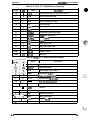
1
EPSON TERM NAL PR NTER
DFX-5000+
SERVICE MANUAL
EPSON
NOTICE
All rights reserved. Reproduction of any part of this manual in any form whatsoever without
SEIKO EPSON’s express written permission is forbidden.
The contents of this manual are subjects to change without notice.
All efforts have been made to ensure the accuracy of the contents of this manual. However, should
any errors be detected, SEIKO EPSON would greatly appreciate being informed of them.
The above notwithstanding SEIKO EPSON can assume no responsibility for any errors in this
manual or the consequence thereof.
Centronics is a registered trademark of Centronics Data Computer Corporation.
Epson and Epson ESC/P are registered trademark of Seiko Epson Corporation.
@Copyright 1994 by SEIKO EPSON CORPORATION Nagano, Japan
-iv-
PRECAUTIONS
Precautionary notations throughout the text are categorized relative to 1) personal injury and 2)
damage to equipment.
DANGER
Signals a precaution which, if ignored, could result in serious or fatal personal injury.
Great caution should be exercised in performing procedures preceded by DANGER
Headings.
WARNING Signals a precaution which, if ignored, could result in damage to equipment.
The precautionary measures itemized below should always be observed when performing repair/
maintenance procedures.
1.
ALWAYS DISCONNECT THE PRODUCT FROM BOTH THE POWER SOURCE AND
PERIPHERAL DEVICES PERFORMING ANY MAINTENANCE OR REPAIR PROCEDURE.
2.
NO WORK SHOULD BE PERFORMED ON THE UNIT BY PERSONS UNFAMILIAR WITH
BASIC SAFETY MEASURES AS DICTATED FOR ALL ELECTRONICS TECHNICIANS IN
THEIR LINE OF WORK.
3.
WHEN PERFORMING TESTING AS DICTATED WITHIN THIS MANUAL, DO NOT
CONNECT THE UNIT TO A POWER SOURCE UNTIL INSTRUCTED TO DO SO. WHEN
THE POWER SUPPLY CABLE MUST BE CONNECTED, USE EXTREME CAUTION IN
WORKING ON POWER SUPPLY AND OTHER ELECTRONIC COMPONENTS.
1.
REPAIRS ON EPSON PRODUCT SHOULD BE PERFORMED ONLY BY AN EPSON
CERTIFIED REPAIR TECHNICIAN.
2.
MAKE CERTAIN THAT THE SOURCE VOLTAGE IS THE SAME AS THE RATED VOLTAGE, LISTED ON THE SERIAL NUMBER/RATING PLATE. IF THE EPSON PRODUCT
HAS A PRIMARY AC RATING DIFFERENT FROM AVAILABLE POWER SOURCE, DO
NOT CONNECT IT TO THE POWER SOURCE.
3.
ALWAYS VERIFY THAT THE EPSON PRODUCT HAS BEEN DISCONNECTED FROM
THE POWER SOURCE BEFORE REMOVING OR REPLACING PRINTED CIRCUIT
BOARDS AND/OR INDIVIDUAL CHIPS.
4.
IN ORDER TO PROTECT SENSITIVE MICROPROCESSORS AND CIRCUITRY, USE
STATIC DISCHARGE EQUIPMENT, SUCH AS ANTI-STATIC WRIST STRAPS, WHEN
ACCESSING INTERNAL COMPONENTS.
5.
REPLACE MALFUNCTIONING COMPONENTS ONLY WITH THOSE COMPONENTS
BY THE MANUFACTURE; INTRODUCTION OF SECOND-SOURCE ICS OR OTHER
NON APPROVED COMPONENTS MAY DAMAGE THE PRODUCT AND VOID ANY
APPLICABLE EPSON WARRANTY.
- ii -.
PREFACE
This manual describes functions, theory of electrical and mechanical operations, maintenance, and repair
of DFX-5000+.
The instructions and procedures included herein are intended for the experience repair technician, and
attention should be given to the precautions on the preceding page. The chapters are organized as
follows:
CHAPTER 1. GENERAL DESCRIPTION
Provides a general product overview, lists specifications, and illustrates the main components of the printer.
CHAPTER 2. OPERATING PRINCIPLES
Describes the theory of printer operation.
CHAPTER 3. DISASSEMBLY AND ASSEMBLY
Includes a step-by-step guide for product disassembly and assembly.
CHAPTER 4. ADJUSTMENTS
Includes a step-by-step guide for adjustment.
CHAPTER 5. TROUBLESHOOTING
Provides Epson-approved techniques for adjustment.
CHAPTER 6. MAINTENANCE AND LUBRICATION
Describes preventive maintenance techniques and lists Lubricants and adhesives required to service the equipment.
APPENDIX
Describes connector pin assignments, circuit diagrams, circuit board component layout and exploded diagram.
The contents of this, manual are subject to change without notice.
- iv -
REVISION SHEET
1
/ Rev.-A
I
Rev.-D
Rev.-E
/ 1 st issue
February 9, 1994
Page 4-10: Addition the notes
Page 4-1 1: Addition the notes
April 20, 1994
Rev.-B
Rev.-C
Revision Page
Issue Data
Revision
,
Page 4-4 to 4-7: Change the explanation
November 22, 1994
1
i December 15, 1994
March 7, 1995
I
Whole Revise of the Chap.4
Page 4-12: Change the explanation
Page 4-12: Addition the notes
TABLE OF CONTENTS
CHAPTER 1.
CHAPTER 2.
CHAPTER 3.
CHAPTER 4.
CHAPTER 5.
CHAPTER 6.
APPENDIX
GENERAL DESCRIPTION
OPERATING PRINCIPLES
DISASSEMBLY AND ASSEMBLY
ADJUSTMENTS
TROUBLESHOOTING
MAINTENANCE AND LUBRICATION
- vi -
CHAPTER 1 Product Description
Table of Contents
1.1 GENERAL FEATURES
1-1
1-3
1.2 SPECIFICATIONS
1.2.1 Printer Capabilities. . . . . . . . . . . . . . . . . . . . . . . . . . . . . . . . . . . . . . . . . . l-3
1.2.2 Paper Handling Specifications. . . . . . . . . . . . . . . . . . . . . . . . . . . . . . . . . l-3
1.2.3 Paper Specifications . . . . . . . . . . . . . . . . . . . . . . . . . . . . . . . . . . . . . . . . 1-5
1.2.4 Ribbon Specifications . . . . . . . . . . . . . . . . . . . . . . . . . . . . . . . . . . . . . . 1-12
1.2.5 Environmental Conditions . . . . . . . . . . . . . . . . . . . . . . . . . . . . . . . . . . . 1-12
1.2.6 Electrical Specifications. . . . . . . . . . . . . . . . . . . . . . . . . . . . . . . . . . . . . 1-13
1.2.7 Reliability. . . . . . . . . . . . . . . . . . . . . . . . . . . . . . . . . . . . . . . . . . . . . . . . 1-13
1.2.8 Safety Approvals. . . . . . . . . . . . . . . . . . . . . . . . . . . . . . . . . . . . . . . . . . 1-13
1.2.9 Physical Specifications . . . . . . . . . . . . . . . . . . . . . . . . . . . . . . . . . . . . . 1-13
1-14
1.3 INTERFACE SPECIFICATIONS
1.3.1 Parallel Interface. . . . . . . . . . . . . . . . . . . . . . . . . . . . . . . . . . . . . . . . . . 1-14
1.3.2 RS-232C Serial interface. . . . . . . . . . . . . . . . . . . . . . . . . . . . . . . . . . . . 1-16
1-17
1.4 PRINTER OPERATION
.1.4.1 Control Panel. . . . . . . . . . . . . . . . . . . . . . . . . . . . . . . . . . . . . . . . . . . . . 1-17
1.4.2 Self-test. . . . . . . . . . . . . . . . . . . . . . . . . . . . . . . . . . . . . . . . . . . . . . . . 1-18
1.4.3 Hexadecimal Dump Function . . . . . . . . . . . . . . . . . . . . . . . . . . . . . . . . . 1-18
1.4.4 Paper Out Detection Function . . . . . . . . . . . . . . . . . . . . . . . . . . . . . . . . 1-18
1.4.5 Cover Open Detection. . . . . . . . . . . . . . . . . . . . . . . . . . . . . . . . . . . . . . 1-18
1.4.6 Paper Width Detection. . . . . . . . . . . . . . . . . . . . . . . . . . . . . . . . . . . . . . 1-19
1.4.7 Automatic PaperThickness Adjustment . . . . . . . . . . . . . . . . . . . . . . . . 1-19
1.4.8 Paper Memory Function . . . . . . . . . . . . . . . . . . . . . . . . . . . . . . . . . . . . 1-19
1.4.8.1 Using the Paper Memory Function . . . . . . . . . . . . . . . . . . . . . . 1-20
1.4.8.2 Saving Paper Format and Thickness Information.. . . . . . . . . . 1-20
1.4.9 Automatic Tear Off Function . . . . . . . . . . . . . . . . . . . . . . . . . . . . . . . . . 1-21
1.4.10 PaperJam Detection. . . . . . . . . . . . . . . . . . . . . . . . . . . . . . . . . ..... 1-21
1.4.11 Automatic Interface Selection . . . . . . . . . . . . . . . . . . . . . . . . . . . . . . . 1-21
1.4.12 Thermal Protection . . . . . . . . . . . . . . . . . . . . . . . . . . . . . . . . . . . . . . . 1-21
1.4.13 Skip Binding Function . . . . . . . . . . . . . . . . . . . . . . . . . . . . . . . . . . . . . 1-22
1.4.14 Printer Initialization . . . . . . . . . . . . . . . . . . . . . . . . . . . . . . . . . . . . . . . 1-22
1.4.15 Buzzer Operation. . . . . . . . . . . . . . . . . . . . . . . . . . . . . . . .......... 1-22
1.5 DIP SWITCH SETTINGS
1-23
1-26
1.6 MAIN COMPONENTS
1.6.1 M-3C11 Printer Mechanism . . . . . . . . . . . . . . . . . . . . . . . . . . . . . . . . . . 1-27
1.6.2 Main Control Board (Cl 17 MAIN Board Assembly). . . . . . . . . . . . . . . . 1-28
1.6.3 Power Supply Circuit (C117 PSB/PSE Board Assembly) . . . . . . . . . . . 1-28
1.6.4 Control Panel Board (C117 PNL Board Assembly). . . . . . . . . . . . . . . . 1-29
1.6.5 Housing . . . . . . . . . . . . . . . . . . . . . . . . . . . . . . . . . . . . . . . . . . . . . . . .. 1-29
List of Figures
Figure 1-1. Exterior View of the DFX-5000+. . . . . . . . . . . . . . . . . . . . . . . . . . . . 1-1
Figure 1-2. Pin Configuration . . . . . . . . . . . . . . . . . . . . . . . . . . . . . . . . . . . . . . . 1-3
Figure 1-3. Printable Area for Fanfold Paper. . . . . . . . . . . . . . . . . . . . . . . . . . . 1-5
Figure 1-4. Unsuitable Paper. . . . . . . . . . . . . . . . . . . . . . . . . . . . . . . . . . . . . . . 1-6
Figure 1-5. Form Override Area. . . . . . . . . . . . . . . . . . . . . . . . . . . . . . . . . . . . . 1-6
Figure 1-6. Perforation Pitch . . . . . . . . . . . . . . . . . . . . . . . . . . . . . . . . . . . . . . . 1-6
Figure l-7. Paper Edge at a Horizontal Perforation . . . . . . . . . . . . . . . . . . . . . . 1-7
Figure l-8. Perforation Intersections . . . . . . . . . . . . . . . . . . . . . . . . . . . . . . . . . 1-7
Figure l-9. Raised Portion at aPerforation . . . . . . . . . . . . . . . . . . . . . . . . . . . . 1-7
Figure 1-10. Sprocket Holes. . . . . . . . . . . . . . . . . . . . . . . . . . . . . . . . . . . . . . . . 1-7
Figure 1-11. Aligned Sprocket Holes . . . . . . . . . . . . . . . . . . . . . . . . . . . . . . . . . 1-7
Figure 1-12. Incorrectly Folded Paper . . . . . . . . . . . . . . . . . . . . . . . . . . . . . . . . 1-8
Figure 1-13. Printable Area, Overlapping Multi-part Forms. . . . . . . . . . . . . . . . 1-8
Figure 1-14. Dotted Paste Positions. . . . . . . . . . . . . . . . . . . . . . . . . . . . . . . . . . 1-9
Figure 1-15. Stapled Area 1 . . . . . . . . . . . . . . . . . . . . . . . . . . . . . . . . . . . . . . . . 1-9
Figure 1-16. Stapled Area 2. . . . . . . . . . . . . . . . . . . . . . . . . . . . . . . . . . . . . 1-9
Figure 1-17. Stapled Area 3. . . . . . . . . . . . . . . . . . . . . . . . . . . . . . . . . . . . . . . 1-10
Figure 1-18. Correct Multi-part Form Binding. . . . . . . . . . . . . . . . . . . . . . . . . . 1-10
Figure 1-19. Printable Area for Fanfold Paper with a Label. . . . . . . . . . . . . . . 1-10
Figure 1-20. Printable Area for Labels. . . . . . . . . . . . . . . . . . . . . . . . . . . . . . . 1-11
Figure 1-21. Label and Carrier. . . . . . . . . . . . . . . . . . . . . . . . . . . . . . . . . . . . . 1-12
Figure 1-22. Data Transmission Timing. . . . . . . . . . . . . . . . . . . . . . . . . . . . . . 1-14
Figure 1-23. Control Panel. . . . . . . . . . . . . . . . . . . . . . . . . . . . . . . . . . . . . . . . 1-17
Figure 1-24. Multi-part Forms with a Label. . . . . . . . . . . . . . . . . . . . . . . . . . . . 1-19
Figure 1-25. overlapping Multi-part Forms. . . . . . . . . . . . . . . . . . . . . . . . . . . . 1-19
Figure 1-26. Main Components . . . . . . . . . . . . . . . . . . . . . . . . . . . . . . . . . . . . 1-26
Figure 1-27. M-3C11 Printer Mechanism . . . . . . . . . . . . . . . . . . . . . . . . . . . . . 1-27
Figure 1-28. C117 MAIN Board Assembly. . . . . . . . . . . . . . . . . . . . . . . . . . . . 1-28
Figure 1-29. C117 PSB/PSE Board Assembly. . . . . . . . . . . . . . . . . . . . . . . . . 1-28
Figure 1-30. C117 PNL Board Assembly. . . . . . . . . . . . . . . . . . . . . . . . . . . . . 1-29
Figure 1-31. Housing . . . . . . . . . . . . . . . . . . . . . . . . . . . . . . . . . . . . . . . . . . . . 1-29
List of Tables
Table 1-1. Options and Consumables . . . . . . . . . . . . . . . . . . . . . . . . . . . . . . . . 1-2
Table 1-2. Character Size and Pitch . . . . . . . . . . . . . . . . . . . . . . . . . . . . . . . . . . 1-3
Table 1-3. Printing Speeds. . . . . . . . . . . . . . . . . . . . . . . . . . . . . . . . . . . . . . . . . 1-4
Table 1-4. Character Tables. . . . . . . . . . . . . . . . . . . . . . . . . . . . . . . . . . . . . . . . 1-4
Table 1-5. Acceptable Environmental Conditions. . . . . . . . . . . . . . . . . . . . . . . 1-12
Table 1-6. Rated Electrical Ranges . . . . . . . . . . . . . . . . . . . . . . . . . . . . . . . . . 1-13
Table 1-7. Parallel lnterface Signals and Connector Pin Assignments. . . . . . . 1-15
Table 1-8. Serial Interface Signals and Connector Pin Assignments . . . . . . . 1-16
Table 1-9. Selecting the Paper Memory Area . . . . . . . . . . . . . . . . . . . . . . . . . 1-20
Table 1-10. Setting the Page Length . . . . . . . . . . . . . . . . . . . . . . . . . . . . . . . . 1-20
Table 1-11. Setting the Paper Type.. . . . . . . . . . . . . . . . . . . . . . . . . . . . . . . . 1-21
Table 1-12. DIP Switch Settings . . . . . . . . . . . . . . . . . . . . . . . . . . . . . . . . . . . . 1-23
Table 1-13. IBM Mode Selection . . . . . . . . . . . . . . . . . . . . . . . . . . . . . . . . . . . 1-23
Table 1-14. ESC/P Mode Selection . . . . . . . . . . . . . . . . . . . . . . . . . . . . . . . . . 1-24
Table 1-15. Interface Selection . . . . . . . . . . . . . . . . . . . . . . . . . . . . . . . . . . . . 1-25
Table 1-16. Baud Rate Selection . . . . . . . . . . . . . . . . . . . . . . . . . . . . . . . . . . . 1-25
Table 1-17. Page Length Selection . . . . . . . . . . . . . . . . . . . . . . . . . . . . . . . . . 1-25
..
Product Description
DFX-5000+ Service Manual
1.1 GENERAL FEATURES
The DFX-5000+ is a 9-pin, serial, dot matrix printer with a maximum speed of 560 characters per
second (cps). It is designed for business use and provides high-speed, high-volume printing and
continuous-sheet handling. The main features of the printer are:
Cl Maximum printing speeds:
560 cps (high-speed draft mode)
504 cps (draft elite mode)
420 cps (draft pica mode)
Cl Advanced paper handling:
-10 inches per second (ips) paper feeding
- Paper jam detection
- Paper width detection
- Front and rear two-way push tractors
- Automatic paper back-out and loading from another paper path and paper park
- Automatic platen gap adjustment for paper thickness
- Automatic tear off
- Paper memory function
- Automatic paper path changing
Cl Eight-bit parallel interface and RS-232C serial interface standard
Cl Epson ESC/P-83 (ESC/P version 83) printer driver (compatible with the FX-870/1170 and
DFX-5000)
D 9 character tables in the standard version
21 character tables in the NLSP (National Language Support) version
Cl Upgraded data handling:
- 20KB input buffer
- Automatic interface selection
- Type B optional I/F cards
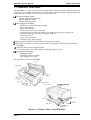
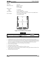
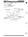
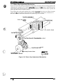
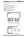
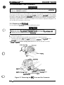
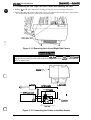
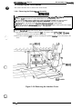
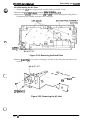
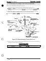
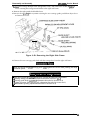
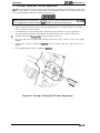
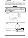
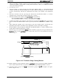
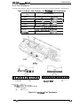
The figure below shows the DFX-5000+.
too cover
“’”’”’”” ‘NV’
control
panel
poper separator
----,
.-n”.fltnrf-flue,
~“p=, >Gpu,..
a”$ - - - -
rial interface
e cover for
I interface
-,
~orallel interface
Figure 1-1. Exterior View of the DFX-5000+
Rev. A
1-1
DFX-5000+ Service Manual
Product Description
Table 1-1. Options and Consumables
I
I
Description
Model
#8309
Pull tractor unit
#8766
Ribbon cartridge
#8767
t
I C82305*
I
I
C82307’
Serial I/F card, SSI, mm screw
1
I 32KB intelligent serial l/F card (inch screw)
C82308*
32KB intelligent serial I/F card (mm screw)
C8231O*
32KB intelligent parallel l/F card
C82312*
LocalTalk l/F card
C82313*
32KB IEEE-488 I/F card
C82306*
C82314*
i
I C82315*
I
Ribbon pack
,
I Serial I/Fcard, simple serial interface** (SSi), inch screw
C82324*
Coax l/F card
I Twinax
I/F card
I Ethernet I/Fcard
‘The digit indicated by an asterisk (*) vanes by country.
● *A simple serial interface card has no CPU; the printer processes the data from
the card.
1-2
Rev. A
Product Description
DFX-5000+ Service Manual
1.2 SPECIFICATIONS
This section provides detailed information about the DFX-5000+.
1.2.1 Printer Capabilities
Printing method:
Serial impact dot matrix
Pin configuration:
9 wires
Pin diameter:
0.29 mm (0.01 inches)
mm (1/72”)
o
8/72”
o
0
0
0
L3I
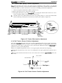
Figure 1-2. Pin Configuration
Dot matrix:
9 x 7 (high-speed draft mode)
9 x 9 (draft mode)
18x 23 (NLQ mode)
Printing direction:
Text mode
Bit image mode
Built-in fonts:
Bidirectional with logic seeking
(Unidirectional mode can be selected using the ESC U command.)
Unidirectional
Draft
NLQ Roman
NLQ Saris Serif
Table 1-2. Character Size and Pitch
Height in mm
(inches)
Pica (1 O cpi)
2.12 (0.08)
3.1 (0.12)
2.54 (0.10)
136
Elite (12 cpi)
1.69 (0.07)
3.1 (0.12)
2.12 (0.08)
163
15 cpi
1.41 (0.06)
3.1 (0.12)
1.69 (0.07)
204
Condensed (17.1 cpi)
1.06 (0.04)
3.1 (0.12)
1.48 (0.06)
233
Condensed elite (20 cpi)
0.85 (0.03)
3.1 (0.12)
1.27 (0.05)
272
Rev. A
Width in mm
Pitch in mm printable Columns
(inches)
(inches)
Type of Letters
I
1-3
DFX5000+ Service Manuai
Product Description
Table 1-3. Printing Speeds
Type of Letters
High Duty (cps)
Print Speed (cps)
533
High-speed draft
420
400
420
400
Draft emphasized pica 20cpi
210
200
NLQ pica
84
80
NLQ elite
101
96
Draft pica 10@
Draft elite 12 cpi
Draft 15 cpi
17 Cpi
Draft condensed pica
Input data buffer:
20KB or O bytes (selectable by DIP switch 2-2)
control codes:
ESC/P-83 mode
Table 1-4. Character Tables
Character Tables
standard
Version
NLSP* Version
IBM Mode
o
0
x
Italic
PC437 (U. S., Standard Europe)
PC850 (Multilingual)
PC860 (Portuguese)
PC863 (Canadian-French)
PC865 (Norwegian)
PC861 (Iceland)
BRASCII
o
Abicornp
o
PC853(Turkish)
PC857(Turkish)
ISO Latin IT (Turkish)
PC437 (Greak)
PC869 (Greek)
ISO 8859-7 (Greek)
PC855 (Cyrillic)
PC866 (Russian)
PC852 (East Europe)
MAZOWIA (Polish)
Code MJK (Czecho, Slovak)
Bulgaria (Bulgaria)
x
o
o
o
o
o
o
x
x
x
x
x
x
x
x
x
x
x
0
0
0
x
0
x
0
x
0
0
0
0
o
o
o
o
o
o
o
o
o
o
o
o
0
x
x
x
x
x
x
x
x
x
x
x
x
x
x
x
0: supported
x: Not supported
*: Nationa/Language Support
1-4
Rev. A
Product Description
DFX-5000+ Service Manual
1.2.2 Paper Handling Specifications
Push tractor feed (front and rear)
Push-pull feed with the optional pull tractor (front or rear)
Feeding methods:
Paper size:
Fanfold paper
Single sheet paper
Roll paper
101 -406 mm (4 - 16 inches) wide
Not available
Not available
1/6- or l/8-inch feed or programmable with a l/216-inch
minimum increment
Line spacing:
Feeding speed
(1/6-inch per line):
Continuous
Intermittent
Note:
17 ins/line (10 inches per second)
26 ins/line
The feeding speed (10 ips) is reduced to 6 ips when the optional pull tractor is installed.
1.2.3 Paper Specifications
Fanfold Paper
Quality:
Plain paper
Width:
101 -406 mm (4 - 16inches)
Copy capability:
Front
Rear
6 sheets (1 original + 5 carbonless copies)
4 sheets (1 original + 3 carbonless copies)
Total thickness:
Front
Rear
Up to 0.46 mm (0.018 inches)
Up to 0.30 mm (0.012 inches)
Weight:
Single
Multi-part
45-70 kg(14- 22 lb)
35-48 kg (11 - 15 lb) x n (n < 8), up to the total thickness
13-31 mm
More than 13mm
~
o
o
.————
wxY~
~
o rABCD
I
I
I
0
0
I
0
0
o
0
I I
o
0
H
E
m
>
g
s
‘o
O~BCD
WXYZJ
-————
0— - — --- — ----- —------0
- — - —w--- :
~~BcD
I
01
A
A
/0
Figure 1-3. Printable Area for Fanfold Paper
Rev. A
1-5
Product Description
DFX-5000+ Service Manual
Notes:
1. Horizontal alignment maybe irregular in the top 75 mm (3 inches) of the first page.
2. When using the optional pull tractor, the top 120 mm (4.8 inches) of the first page are
unprintable.
3. Use clean paper with no folds, creases, or tears (especially for multi-part paper). Figure 1-4
shows paper you should not use.
creases
Figure 1-4. Unsuitable Paper
4.
Form override printing is available for 20 lines after the paper end. The paper feeding pitch is
not guaranteed. The end of the printable area is 15 mm (0.60 inches) above the bottom edge of
the paper.
A
A
o
:p6D— -— ~lo
–
o
0
I
10
10
‘o
0’
0
o‘
o
E
In
w)(wJ
L%D—. —END OF PAPER
,
s
,~
1$E il
V
If?
Figure 1-5. Form override Area
5.
6.
Weak horizontal and vertical perforations cause paper jams.
The pitch of perforations (the ratio of the cut part to the uncut part) must be less than 5:1.
cut
_f&__t?tVE!?L
Figure 1-6. Perforation pitch
1-6
Rev. A
DFX-5000+ Service Manual
7.
Product Description
Horizontal perforations must have uncut parts on both edges of the paper.
-’/
Uncut
[
———
Paper edge
cut
l_-
Figure 1-7. Paper Edge at a Horizontal Perforation
8.
At the intersection of a horizontal and vertical perforation, the perforation cuts must not cross
each other. Figure 1-8 shows examples of correct perforation intersections.
I
I
-——.
II
I
——I
I
I
———
I
I
Figure 1-8. Perforation Intersections
9.
The raised portion at a perforation (fold) must be less than 1 mm (0.04 inches) from the flat
part, and the bottom layer must be kept flat by force.
Perforations
Figure 1-9. Raised Portion at a Perforation
10. Sprocket holes must be circular and may have teeth.
OC3
Figure 1-10. Sprocket Holes
11. The sprocket holes of each paper layer must be properly aligned.
3
NG
o
-b
U
0
II
Figure 1-11. Aligned Sprocket Holes
Rev. A
1-7
DFX-50oo+ Service Manual
Product Description
12. Any pieces of paper remaining in the sprocket holes must be removed.
13. The paper should be fanfolded at the horizontal perforations. Never use incorrectly folded
paper, such as the paper shown below.
NG
Figure 1-12. Incorrectly Folded Paper
14. Make sure there are no holes in the printable area.
15. The paper must be tom off cleanly along a perforation.
Overlapping Mutti-part Forms
Paper path:
Front only
Quality:
Plain paper
Width:
101-406 mm (4 -16 inches)
Copy capability:
Overlap length:
5 sheets (1 original + 4 carbonless copies), excluding the bottom
carrier
10 mm (0.394 inches) maximum
Total thickness:
Print area
Overlap area
0.46 mm (0.018 inches) maximum
0.70 mm (0.028 inches) maximum, including the bottom carrier
Weight:
Multi-part
Carrier
35-48 kg (11 - 15 lb), up to the total thickness
45- 70kg (14- 221b)
More than
13mm
13-31mm
--D
—
Perforations
/
./
o
-------------——— —..— ——.
0 Ma)
z
T
4 -
r
7
o
Carrier o
0
0
-.
0
-.
0
0
0
0
0
0
-.
0
5
—
o
o
A
0
—
Figure 1-13. Printable Area, Overlapping Multi-part Forms
.1
DFX-5000+ Service Manual
Product Description
r,
Ii
When using overlapping multi-part forms, do not use the paper select (change tractors) or tear
offfunction; to avoid a paper jam, it is important not to feed overlapping multi-part forms
backward.
Notes:
1.
Rough multi-part form binding causes paper jams.
2. The multi-part form sheets should be bound together with spot gluing (dotted paste), paper
stapling (mechanical staking), or tape stitching. Forms joined with spot gluing are
recommended for the best printing quality.
3. For multi-part forms joined with dotted paste, the form sheets can be joined on either a single
side or both sides. Figure 1-14 shows the recommended paste positions.
Surface
o
a
“
o
m
0
o
-------------------
0
0
Ea
m
0
0
0
0
m
m
0
0
0
0
mB-
W
0
0
0
0
m
0
0
-------------------
Figure 1-14. Dotted Paste Positions
4. The pasted areas must be pressed flat. There must be no creases in the paper.
5. Paper stapling must be applied from the front, and the paper must be flat. Figure 1-15 shows a
cross section of the stapled area.
a: Less than paper thickness
Figure 1-15. Stapled Area 1
6. Paper stapling must be applied for both feeding directions. Figure 1-16 shows a cross section of
the stapled area.
Paper feeding direction
Figure 1-16. Stapled Area 2
Rev. A
1-9
DEMO(M+ Servke hisnual
Pfvduct Descfiptkm
7.
The binding area must be fiat. Figure 1-17 shows a cross section of the stapled area.
NG
Figure 1-17. Stapled Area 3
8. Never use forms joined with metal staples.
9. The binding (dots of paste or paper staples) must be outside the printable area.
10. Overlapping multi-part forms must be bound at the top side by spot gluing. The binding must
be secure and there should be no spilled giue. Figure 1-18 shows the correct multi-part form
binding method.
11. Multi-part firm sheets should be securely bound to each other, and the binding area must not
be too large.
Paate
Figure 1-18. Correct Muiti-part Form Binding
Fanfold Paper with a Labal
Paper path:
Front only
Quality:
Plain paper
Width:
Total thickness:
101-406 mm (4 - 16 inches)
0.46 mm (0.018 inches) rruximum
Weight:
Single
Multi-part
4 5 - 70kg(14- 221b)
35- 48kg (11 -15 lb) x n (n < 8), up tothe total thickness
No pmling area
. -,. \
c’
~‘ t
-,
‘w
13nml
01
A
A
10
Figure 1-19. Printabie Area for Fanfoid Paper with a Labei
1-1o
Rev. A
Product Description
DFX-5000+ Service Manual
Labels
Paper path:
Front only
Label size (W x H):
2%x 15/16 inches
4 x 15/16 inches
4 x 17/16 inches
Bottom carrier:
Width
Length
Total thickness:
Label examples:
4- 16 inches
3.5 inches minimum
0.19 mm (0.0075 inches) maximum
Differences in thickness must be less than 0.12 mm (0.0047 inches).
Avery continuous form labels
Avery mini-line labels
“
0o IIr-lr-l
II
I 10
I
01
0
I
0
0
0
0
0
o
I
II
I 10
II
L.-----H---J o
r-l~-l!o
10
II
II
H
10
A
11
0
Inside of each. label
Figure 1-20. Printable Area for Labels
When using labels, do not use the paper select (change tractors) or tear oflfinction; to avoid a
paper jam, it is important not to feed label forms backward.
Notes:
1.
2.
3.
4.
Load label forms only onto the front tractor. The paper select function must not be used.
Feed label forms only in the forward direction, using the forward-feeding MICRO FEED
button (A). Do not feed label forms in the reverse direction. (Feeding label forms backward
may cause a paper jam, or the labels may come off the backing and stick to the printer.)
When using label forms, do not use the TOF (top of form) function.
5.
6.
7.
Do not use easy-peel labels.
Label comers must be rounded.
The labels and the bottom carrier should have no folds or creases.
Labels must be on carrier paper, and there should be carrier paper between the labels. (The
labels should not touch each other.)
8.
The label surface must be flat.
Rev. A
1-11
DEX-50(W+ Service hWw81
Product Description
4-16”
r
I
A
A
o--------------------------[ H
J .-o
0’
r-- r
O,
~
‘T 0
‘k’ j i ‘*e’ j
10; r-l
r‘7
bb’ i i ‘ab’ j,
0
o
0----------------------------~ ~
o
o
0(
H A
\
H
v
~w
r
Figure 1-21. Label and Carrier
1.2.4 Ribbon Specifications
Ribbon cartridge:
#8766
Ribbon pack:
#8767
Ribbon pack exchanges:
4 times per cartridge maximum
Ribbon color:
Black
Dimensions:
Cartridge
Ribbon
506 (W) X 23 (H) X 140(D) mm (20.24X 0.92 x5.60 inches)
13 mm x 70 m (0.52 inches x 231.0 tit), endless
Life:
15 million characters (14 dots/character)
1.2.5 Environmental Conditions
Table 1-5. Acceptable Environmental Conditions
Condition
Temperature
Humidity
Shock resistance
Vibration resistance
● ’: 7hese conditions are
●2: wjj~mnsationm
Operating
storage
5- 35°C (41” - 95”F)
-30- 80”C (-22 - 140”F) “’
10-
WY.
RH q
5- 85% RH ““v
1 G (within 1 msec.)
2 G (within 2 maec.)”
0.25 G, 55 Hz maximum
0.50 G, 55 Hz maximum
acceptable when theprinterisin itssh@ping mntainer.
..c..? ,
‘{
. ...~
.4
1-12
Rev. A
DFX-5000+ Service Manual
Product DescriMion
1.2.6 Electrical Specifications
Table 1-6. Rated Electrical Ranges
120 V Version
220-240 V Version
120 VAC
I
220-240 VAC
103.5- 132 V
I
198-264 V
Rated frequency range
5 0 - 6 0 HZ
I
5 0 - 6 0 tiz
Input frequency range
49.5 -60.5 Hz
49.5 -60.5 tiz
5.0 A
3.0 A
Approx. 115 W
(self-test in 10 cpi draft mode)
Approx.110 W
(self-test in 10 cpi draft mode)
Rated voltage
Input voltage range
Rated current
Power consumption
Insulation resistance
Dielectric strength
10 MQ minimum
10 MQ, minimum
(applying 500 VDC between AC line (applying 500 VDC between AC IHw
and chassis)
and chassis)
1000 VAC rms -1 minute or
1200 VAC rrns -1 second
(between AC line and chassis)
1500 VAC rrns -1 minute
(between AC line and chassis)
1.2.7 Reliability
MTBF:
8000 power-on hours (POH) at a duty cycle of zs~o
MCBF:
Printhead life:
24 million lines (excluding the printhead and ribbon)
300 million characters (14 dots/character)
1.2.8 Safety Approvals
Safety standards:
U.S. version:
European version:
Radio frequency interference (RFI):
U.S. version:
European version:
UL1950 with D3
CSA22.2 #950 with D3
EN 60950 ~, SEMKO, DEMKO,
NEMKO, SETI)
FCC part 15 sub-part B class B
Vfg 243 (VDE 0878 part 3)
CISPR Pub 22 class B
1.2.9 Physical Specifications
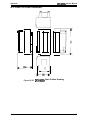
Size (W x D x H):
700 x 382x 369 mm (27.6 x 15.0 x 14.5 inches)
Weight:
29 kg (63.8 lb)
Rev. A
1-13
LKMO#+ Serukw Mwd
Product Description
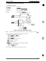
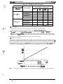
1.3 INTERFACE SPECIFICATIONS
1.3.1 Parallel Interface
Data forrmt:
8-bit parallel
Synchronization:
“
tion
By STROBE Pllk Sy’dWXWa
Handshaking:
By BUSY and ACKNLG
Signal level:
TT’compatible level
Connector:
%-pm 57-30360 (Amphenol) or equivalent
SigdS
ACKNLG
.,
6!’!?
DATA
‘. .>..‘,$
,:,
&
L 0.5uS(Min.)
O.SuS(Min.)
0.5uS(Min.)
Figure 1-22. Data Transmission Timing
Note:
The transition time (the rise and fall time) of each input signal must be less than 0.2 ILS.
The BUSY signal is active (HIGH) under the following conditions:
- During data reception (See Figure 1-22.)
- When the ~t buffer is full
- When the INIT’ input signal is active
- During initialization
- When the ERROR or PE signal is active
- During the self-test
- II-I paper memory setting mode
- IrI pause mode
- When a fatal error occurs
The ERROR signal is active (LOW) under the following conditions:
- When a paper out error occurs
- When a paper jam error occurs
- When a fatal error occurs
The PE signal is active (HIGH) when a paper out error occurs.
1-14
Rev. A
Product Description
DFX-5000+ Service Manual
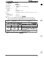
Table 1-7 shows the signal functions and connector pin assignments for the 8-bit parallel interface.
Table 1-7. Parallel Interface Signals and Connector Pin Assignments
Pin No.
1
Signal Name
STROBE
Return
Pin No.
I/o’
19
I
STROBE pulse to read the input data. The
pulse width must exceed 0.5 @. Input data is
latched after the falling edge of this signal.
20-27
I
Parallel input data to the printer.
HIGH level means data 1.
LOW level means data O.
Description
2-9
DATA 1- DATA 8
10
ACKNLG
28
0
This pulse indicates data has been received
and the printer is ready to accept the next data.
The pulse width is approximately 12 p.s.
11
BUSY
29
0
HIGH indicates the printer cannot accept the
next data.
12
PE
30
0
HIGH indicates paper out. This signal is
effective only when the ERROR signal is LOW.
13
SLCT
o
Always HIGH output. (Pulled up to +5 V
through a 3.3 KQ resistor.)
14
AFXT
I
If the signal is LOW when the printer is
initialized, a line feed is automatically
performed when a CR code is input (auto LF).
15,34
NC
No connection (not used).
16
Ov
Signal ground level.
17
FG
Chassis ground. In the printer, chassis ground
and signal ground are short circuited.
-
18,35
+5 v
Pulled up to +5 V through a 3.3 KQ resistor.
19-30
GND
Ground for twisted-pair return signal.
31
INIT
I
Pulse input (width: 50 p.s minimum, active
LOW) for printer initialization.
32
ERROR
o
LOW indicates that some error has occurred in
the printer.
33
GND
36
SLCTIN
Signal ground.
I
If the signal is LOW when the printer is
initialized, DC1/DC3 control is disabled.
*The 1/0 column indicates the direction of the signal as viewed from the printer.
Rev. A
1-15
DEX401W+ Servka Mm&#
Product Lkscription
1.3.2 RS-232C Serial Interface
Data format:
RS-232C serial
Synchronization:
Asynchronous
Handshaking:
By DTR signal or X-ON/X-OFF protocol
Word length:
Start bit
Data bit
Parity bit
Stop bit
1 bit
8 bits
Odd, even, or no parity
1 bit or more
Bit rate:
300,1200,9600, or 19200 bps (selectable by DIP switches 2-7 and 2-8)
Logic level:
MARK (logical 1)
SPACE (logical O)
-3 to –27 V
+3 to +27 V
Connector:
EIA standard 25-pin cmnector
Table 1-8 shows the signal functions and connector pin assignments for the serial interface.
Table 1-8. Serial Interface Signals and Connector Pin Assignments
Pin No.
1
2
I
r
I
FG
TXD
I I/o* I
.
I
I
O
I
3
RXD
7
SG
I
.
DTR
o
11,20
4-6,8-10,
12-19.21-25
●
Signal Name
I
NC
I .
Description
I Chassis ground.
[
TmllSmt*tafOrx-Ow-OFF
I
hndShake.
I
I
Receive data.
Signal ground.
Indicates whether the printer is ready to receive
data. If the printer is not ready, the DTR signal
becomes MARK.
No connection (not used).
The PO column indicates the data flow as tiewed fmm the printer.
Pj
.>,;, ,
0
,,,’; .;.,,,
1-16
Rev. A
Product Description
DFX-5000+ Service Manual
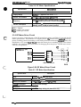
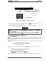
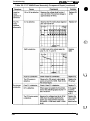
1.4 PRINTER OPERATION
This section describes the basic operation of the printer.
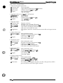
1.4.1 Control Panel
The printer’s control panel contains eight non-lock type push buttons and twelve LED indicators
for easy use of the various printer functions.
Cl POWER
PAUSE
LFIFF
LOAO
TEAR OFF
n PAPER
OUT
MICRO FEEO
m
TOP OF
‘
O
R
PITCH
M
A
cl
0
0
‘
o
12
in
a
m
a
PAPER SELECT
g m
~o
B
FRONT/REAR
(e)
(A)
(B)
(c)
Figure 1-23. Control Panel
Buttons
PAUSE:
LF/FF LOAD:
TEAR OFF:
Stops or starts printing, if any print data exists in the input buffer. (Turns
pause mode on or off.)
Advances the paper line by line according to the set line spacing while the
printer is ready to print or paused by the PAUSE button. Holding down the
button for about one second advances the paper to the next top of form
(TOF) position. This button is also used to load the paper from the push
tractor of the selected paper path when the printer is in the paper-out state.
Enables tear off mode and advances the paper to the tear off position. This
button functions only when the printer is in pause mode. The tear off
position can be adjusted using the MICRO FEED buttons. The adjusted value
is stored in the EEPROM on the main board when the printer is turned off.
TOP OF FORM:
Adjusts the paper position, including the top of form (TOF) and tear off
positions. The forward MICRO FEED button (A) advances the paper in 1/216
inch increments and the backward MICRO FEED button (v) feeds the paper
backward in 1 /216 inch increments.
Enables top of form (TOF) setting mode, so that the TOF position can be
adjusted using the MICRO FEED buttons. This button functions only when
paper is loaded into the printer using the LF/FF LOAD button and the
printer is in pause mode. In TOF setting mode, the PAUSE LED is lit and the
TOF LED blinks.
PITCH:
Selects a character pitch of 10,12, or 17 cpi.
PAPER SELECT:
Selects the front or rear paper path. If there is paper in the current path and
the printer is in pause mode, the paper is fed backward to the tractor. Then,
the selected paper from the other tractor is fed to the TOF position. If all the
paper in the current path is not fed backward to the tractor by the single
22-inch (55.9-cm) backward feeding sequence, make sure your previous
print job is tom off and press the PAPER SELECT button again until the
current path is empty.
MICRO FEED:
Rev. A
1-17
DFX-5009+ Servkm MwnuJ
Product Descrhtion
LED Indicators
POWER (green):
Lit when the printer is turned on.
PAPER OUT (red):
Lit when the printer is out of paper.
Flashes when there is a paper jam.
Lit when the printer is in pause mode.
PAUSE (orange):
TEAR OFF (orange):
TOP OF FORM (green):
Lit when the printer is in tear off mode.
PITCH (3) (green):
The lit PITCH LED indicates the selected pitch.
Lit when the front paper path is selected with paper loaded onto the
front tractor.
Lit when the front paper path is selected with no paper loaded onto
the front tractor.
FRONT (2) (green):
(red):
REAR (2) (green):
(red):
Lit when the printer is in TOF mode.
Lit when the rear paper path is selected with paper loaded onto the
rear tractor.
Lit when the rear paper path is selected with no paper loaded onto
the rear tractor.
1.4.2 Self-test
The printer’s self-test (self printing) function checks the following
- Control arcuit
Printer mechanism
Print quality
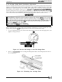
To run the self-test in draft* mode, hold down the LF/FF LOAD button and turn on the printer. To
run the self-test in NLQ mode, hold down the TEAR OFF button and tmm on the printer.
The self-test can be interrupted by pressing the PAUSE button. To end the self-test, press the
PAUSE button and then turn off the printer.
The self-test prints the following:
- Program ROM version number
– Built-in characters
To print the current DIP switch settings, hold down the PAUSE button and turn on the printer.
* The printer does not print the self-test in draft mode if NLQ mode is selected using
DIP switch 1-3.
1.4.3 Hexadecimal Dump Function
The hexadecimal dump function prints the data the printer receives in hexadecimal format. To
print a hexadecimal dump, hold down the LF/FF LOAD and TEAR OFF buttons and turn on the
printer. “HEX DUMP MODE” is printed on the first line. Then 16 bytes an? printed in hexadedmal
on each line, and the ASCII character correspondkg to each byte is printed on the right side. “.” is
printed if there is no corresponding ASCII character (such as, for a control code). If less than 16
bytes remain, they can be printed by pressing the PAUSE button. To cancel hexadecimal dump
mode, turn off the printer.
1.4.4 Paper Out Detection Function
When the paper out sensor detects the printer is out of paper, the printer automatically enters
pause mode. Load new paper properly, and then press the PAUSE button to turn off pause mode
so the printer is ready to print.
1.4.5 Cover Open Detection
When the printer cover is opened, the printer stops printin& beeps 4 times with 0.1 second
intervals, and enters pause mode. Close the printer cover and press the PAUSE button to turn off
pause mode so the printer is ready to print.
1-18
Rev. A
Product Description
DFX-5000+ Service Manual
1.4.6 Paper Width Detection
The printer detects the right paper edge and determines the right end of the printable area. This
disables printing in areas where there is no paper.
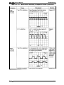
1.4.7 Automatic Paper Thickness Adjustment
The printer measures the paper thickness each time paper is loaded. The distance between the
printhead and the platen is automatically adjusted to match the paper’s thickness and obtain the
best print quality.
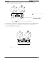
1.4.8 Paper Memory Function
The paper memory function allows the printer to print properly when different areas of the same
form vary in thickness. For the best print quality when using forms with a label or overlapping
forms, use the paper memory function. It allows you to save paper format and thickness
information using the DIP switches and the control panel buttons. The paper memory function is
available only for forms loaded on the front tractor.
Cl Forms with a label
Multi-part forms that vary in thickness include forms with a label; the label area is thicker
than the rest of the form.
0
0
Figure 1-24. Multi-part Forms with a Label
Q Multi-part forms that partly overlap the next page
Multi-part forms that vary in thickness include forms that overlap slightly where they are
glued together; the overlap area is twice as thick as the rest of the form.
Figure 1-25. Overlapping Multi-part Forms
Set the information about the label and overlap areas before printing. The printer works according
to this information.
Note:
Rev. A
The tear off and paper select functions are not available when the paper memory function
is used.
1-19
DFX-5000+ Servke Manual
Product Description
1.4.8.1 Using the Paper Memory Function
To use the paper memory function, you must first save paper format and thickness information for
up to two different types of paper as described in fktion 1.4.8.2, below.
To turn on the paper memo~ function after saving your paper format and thickness information,
hold down one of the buttons below and turn on the printer.
MICRO FEED
Recalls the paper format and thickness information stored
in memory area 1.
RecaIls the paper format and thickness information stored
in memory area 2.
(A)
MICRO FEED (v)
To turn off the paper memory function and use normal paper, hold down the PAPER SELECT
button and turn on the printer.
Notes: Cl A l-inch skip over perforation area is automatically included for overlapping forms.
Ct ESC C (set page length) is valid when using the paper memory function.
O ESC N (set skip over perforation) is valid when using the paper memory function;
however, if the skip length is less than 1 inch, the setting is ignored when using
overlapping forms.
Q ESC O (reset skip over perforation) is valid when using the paper memory function
with overlapping forms.
Q When using overlapping forms, the loading position must be adjusted each time you
load paper.
1.4.8.2 Saving Paper Format and Thickness Information
To save paper format and thickness information for overlapping forms, forms with a label, or
overlapping forms with a label, follow these steps:
1. Turn off the printer.
2. Use DIP switch 3-4 to select the memory area where you want the printer to store the paper
format and thickness information. Memory area 1 is sekcted when DIP switch 3-4 is off. This
is the printer’s default setting. To select memory area 2, turn on the switch.
Table 1-9. Selecting the Paper Memory Area
Paper Memory Area
DIP SW 3-4
1
OFF
2
ON
3. Use DIP switches 3-1 and 3-2 or softwareco rnmands to set the page length.
Table 1-10. Setting the Page Length
Page Length (inches)
DIP SW 3-1
DIP SW 3-2
11
OFF
OFF
12
OFF
ON
8.5
ON
OFF
70/6
ON
ON
.o, :., .
1-20
Rev. A
Product Description
DFX-5000+ Service Manual
4.
Use DIP switches 3-5 and 3-6 to set the paper type.
Table 1-11. Setting the Paper Type
Sw 3-5
Sw 34
Normal paper
OFF
OFF
Forms with a label
OFF
ON
Overlapping forms
ON
OFF
Paper Type
Overlapping forms with a label
I
ON
[
ON
5. Hold down both MICRO FEED buttons and turn on the printer.
6. If you are using forms with a label, indicate the label’s position by following these steps:
(1) Open the printer cover.
(2) Align the pointer on the ribbon mask with one of the label’s comers.
– To feed the paper up or down, press the appropriate MICRO FEED button.
– To move the pointer right or left, move the printhead by hand.
(3) Press the TOP OF FORM button.
(4) Move the pointer to the comer of the label diagonally opposite the first comer.
(5) Press the TOP OF FORM button.
(6) Close the printer cover.
7. Use the printer beeps to confirm that the paper format and thickness information has been
saved properly. If the printer beeps once or twice, the information has been saved correctly in
memory area 1 or 2. If the printer beeps 10 times, the information has not been saved; carefully
follow steps 1 through 7 in this section again.
1.4.9 Automatic Tear Off Function
Use DIP switch 3-8 to enable or disable the automatic tear off function. When the tear off function is
enabled, the printer automatically feeds fanfold paper until its perforation reaches the tear off
position of the printer cover under these conditions:
Cl The paper is advanced to the TOFposition after a print job.
Q The printer receives an FFcode and then no other codes or characters for at least3 seconds. (The
printer has finished a print job.)
Ll The pull tractor is not being used.
D The paper memory function is not being used.
Then, if the printer receives more data, it automatically feeds the paper backward to the original
position and printing starts.
1.4.10 Paper Jam Detection
When a paper jam is detected, the printer beeps, stops feeding the paper, and enters pause mode.
The PAPER OUT indicator flashes. Remove the paper and load new paper properly. Then press the
PAUSE button to turn off pause mode so the printer is ready to print.
1.4.11 Automatic Interface Selection
When the printer does not receive any data tbr the set time over the currently selected interface, it checks
the parallel interfam, serial interfam, and optional interfam, and selects the intert%ce that receives data fit.
The standby time can beset to 10 seconds or30 seconds using DIP switches 24,2-5, and 245.
Note:
The built-in serial interface and Type B simple serial interface card cannot be used at the
same time. The simple serial interface card takes precedence over the built-in serial
interface.
1.4.12 Thermal Protection
The printhead has a thermistor inside it, and the printhead cooling fan also has a thermistor. When
the pnnthead or cooling fan is too hot, the printer stops printing while it cools.
Rev. A
1-21
DEW(W)+ Service Mmual
Product Dascrfption
1.4.13 Skip Binding Function
The skip binding function is used for printing on multi-part forms with binding that could scratch
the printhead during paper feeding. When this function is used, the head parks away from the
binding during paper feeding to avoid paper jams. Use DIP switch 3-7 to enable or disable the skip
binding function; when it is enabled, throughput is reducwl.
1.4.14 Printer Initialization
The printer is initialized in the following cases:
Lt When thep@er is turned on.
il men the NIT signal is input through the parallel rnterface.
Initialization performs the following functions:
Returns the printhead to th~ far left position (carriage home).
Puts the printer in ready mode, so it is ready to print.
Clears the print buffer and input data buffer.
Clears download characters (CG ROM copy in IBM mode).
Sets the line spacing to 1/6 inch.
Sets the page length according to the DIP switch settings.
Clears all vertical tab positions.
Sets the horizontal tab position to every 8 columns.
Sets the print mode according to the DIP switch settings and non-volatile memory.
The top of form (T’OF) position is reset by the following:
~ Printer initializ.ation
Li ESC/P software reset command (ESC @)
~ Page length command (ESCC)
2 IBM top-of-form setting command (ESC4)
1.4.15 Buzzer Operation
The buzzer sounds for approximately 0.1 second when a BEL code (07H) is input. Buzzer beeps
indicate printer status, as shown below. Each asterisk (*) represents one 0.1 second beep.
The ESC BEL command (07H) is input.
A carnage error is detected due to:
CRlockup.
Low insulation resistance (less than 1 IQ.
A paper out or paper jam is detected.
(The printer runs out of paper or a paper jam
occurs during paper feeding or printing.)
Another paper error is detected:
Incomplete back+ut. (The previous print
job is not tom off.)
Empty during operation. (The paper is out
at power on.)
An abnormal voltage is detected.
RAM error is detected.
A cover open is detected:
The cover open sensor detects that the
cover is open.
The interlock switch detects that the
cover is open.
A short circuited printhead is detected.
(The head driver FETs are bad.)
A short circuited printhead fan is detected.
An illegal paper memory setting is detected.
A micro adjust limit is detected.
A platen gap adjust error is detected.
* *0.3 sWmd interval
** 0.1 second interval
Note:
1-22
*(1 beep)
“** “w (2 sets of 3 beepa)
●
*** ‘* *-*‘~ ****(5
sek
of 4 beeps)
c’”
*“* (3 beeps)
* **•” (sbeepswi~ a w= ~ tween each beep)
** w ** ** ● * (5 SPJS of z beeps)
*** (4 beeps)
* * * * ● ● * * ● * (II) &P ~~ a Pam between
~? ~ - ** ● * - ** ** (B *S of 2 ~)
**** W-* @ *S,
each beep)
***-**-**... (continuom beeps)
*** *** *** (3* of 3 *)
Rev. A
Product Description
DFX-5000+ Service Manual
1.5 DIP SWITCH SEITINGS
This section describes the functions of the DIP switches. After settimz one or more DIP switches,
turn on the printer to put your settings into effect.
Table 1-12. DIP Switch Settings
SW No.
ON
Function
Factory
Setting
OFF
I
1-1
Emulation mode
OFF
1-2
Drafl speed
OFF
1-3
Character quality
OFF
1-4
1-5
1-6
1-7
1-8
IBM mode
ESC/P mode
See Table 1-13.
See Table 1-14.
OFF
OFF
OFF
OFF
OFF
2-1
Shape of zero
2-2
Input buffer
2-3
Automatic LF bv CR
2-4
2-5
2-6
E
Interface
See Table 1-15.
OFF
OFF
OFF
2-7
2-8
Serial bit rate
See Table 1-16.
OFF
OFF
3-1
3-2
Page length
See Table 1-17.
OFF
OFF
3-3
Skip over perforation
Valid (1”)
Invalid
OFF
3-4
Paper memory area**
2
1
OFF
3-5
Overlapping forms**
Valid
Invalid
OFF
3-6
Forms with a label**
Valid
Invalid
OFF
3-7
Skip binding
Valid
Invalid
OFF
3-8
Automatic tear off
Valid
I Invalid
OFF
OFF
OFF
OFF
* IBM mode indicates IBM ProPrinter emulation mode.
** These DIP switches are used forpaper memory function settings.
Table 1-13. IBM Mode Selection
I
I
I
t
Function
SW No.
Rev. A
1-4
Automatic CR by LF, ESC J
1-5
Reserved
1-6
Codes 80-9FH
1-7
Reserved
1-8
Character table
ON
Invalid
I
OFF
Valid
Factory
Setting
OFF
OFF
Characters
Commands
OFF
OFF
PC865
PC437
OFF
1-23
Product Description
DEW50tM+ Swvke Manual
Table 1-14. ESC/P Mode Selection
Character Table
Sw 1-4 Sw l-a Sw l-e Sw 1-7 Sw 14
NLSP
Standard
1-24
Italic Us.
OFF
OFF
OFF
OFF
OFF
Italh France
OFF
OFF
OFF
OFF
ON
Italk Germany
OFF
OFF
OFF
ON
OFF
Itzk U.K.
OFF
OFF
OFF
ON
ON
Italic Denmark
OFF
OFF
ON
OFF
OFF
Italic Sweden
OFF
OFF
ON
OFF
ON
Italic Italy
OFF
OFF
ON
ON
OFF
Italii Spain
OFF
OFF
ON
ON
ON
PC437
PC437
OFF
ON
OFF
OFF
OFF
PC850
PC850
OFF
ON
OFF
OFF
ON
PC860
PC860
OFF
ON
OFF
ON
OFF
PC863
PC863
OFF
ON
OFF
ON
ON
PC865
PC865
OFF
ON
ON
OFF
OFF
PC861
PC861
OFF
ON
ON
OFF
ON
BRASCII
BRASCII
OFF
ON
ON
ON
OFF
Abicomp
Abicomp
OFF
ON
ON
ON
ON
PC437 Greek
ON
OFF
OFF
OFF
OFF
PC869
ON
OFF
OFF
OFF
ON
1s0 8859-7
ON
OFF
OFF
ON
OFF
PC853
ON
OFF
OFF
ON
ON
PC857
ON
OFF
ON
OFF
OFF
ISO Latin IT
ON
OFF
ON
OFF
ON
PC865
ON
OFF
ON
ON
OFF
PC866
ON
OFF
ON
ON
ON
PC852
ON
ON
OFF
OFF
OFF
MAZOWIA
ON
ON
OFF
OFF
ON
Code MJK
ON
ON
OFF
ON
OFF
Bulgaria
ON
ON
OFF
ON
ON
Rev. A
Product Description
DFX-5000+ Service Manual
Table 1-15. Interface Selection
Interface
Sw 2-4
SW 2-5
Sw 2-6
Automatic selection, serial interface, odd parity (30 seconds*)
OFF
OFF
OFF
Automatic selection, serial interface, odd parity (10 seconds*)
OFF
OFF
ON
Automatic selection, serial interface, no parity (30 seconds*)
OFF
ON
OFF
Automatic selection, serial interface, no parity (10 seconds*)
OFF
ON
ON
Parallel interface
ON
OFF
OFF
Serial interface, odd parity
ON
OFF
ON
Serial interface, even parity
ON
ON
OFF
Serial interface, no parity
ON
ON
ON
*This is the standby time. See Section 1.4.11, ‘Automatic Interface Selection.”
Table 1-16. Baud Rate Selection
Bit Rate (bps)
SW 2-7
Sw 2-8
19,200
OFF
OFF
9,600
OFF
ON
1,200
ON
OFF
300
ON
ON
Table 1-17. Page Length Selection
Rev. A
Page Length
Sw 3-1
SW 3-2
11 inches
OFF
OFF
12 inches
OFF
ON
I
8.5 inches
I
70/6 inches
I
ON
ON
I
OFF
ON
~ 1-25
DEX4i’W+ Swvice Msnusl
Pfvduct Dwcription
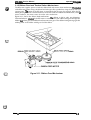
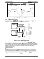
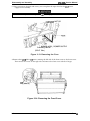
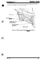
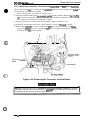
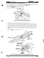
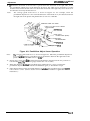
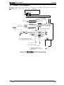
1.6 MAIN COMPONENTS
The main components of the DFX-5000+
are designed fix easy removal and replacement. These
e
main components are:
Printer mechanism (M-3C11)
Main control board (C117 MAIN board assembly)
Power supply board ( C117 PSB/PSE board assembly)
Control panel (C117 PNL board assembly)
Housing
Connector Junction Board
,.’ .+.
,,.. ..,;,
@
Y
c
Figure 1-26. Main Components
1-26
Rev. A
DFX-5000+ Service Manual
Product Description
1.6.1 M-3CI 1 Printer Mechanism
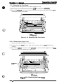
The M-3C11 printer mechanism is a 9-pin, serial, dot matrix printer mechanism developed for the
DFX-5000+. It is designed to provide high-speed, high-volume printing, and is especially heavy
and durable when compared with existing terminal printer mechanisms. Its paper feeding
mechanism uses fanfold paper, and an automatic mechanism is included to provide enhanced
paper handling.
The structural differences between the DFX-5000+ and the DFX-5000 are:
U The DFX-5000+ includes a CR motor isolation resistance sensor.
Ll The DFX-5000+ includes a paper jam sensor.
Cl To prevent paper jams, the DFX-5000+ includes a tractor wire at the front and rear tractors.
U The DFX-5000+ does not include a carriage home position sensor.
LI The detection method of the carriage encoder sensor has been changed. In the DFX-5000, the
encoder plate was attached to the rotor of the CR motor, while the DFX-5000+ uses a belt-type
encoder.
Cl In the DFX-5000+, the angle between the printhead and the surface of the platen has been
changed to reduce noise.
El In the DFX-5000+, the ribbon guide is not attached to the ribbon mask; the ribbon mask is
attached to the pnnthead carriage.
Figure 1-27. M-3C11 Printer Mechanism
Rev. A
1-27
DEX-45000+ Service Manual
Product LA9ecriotkn
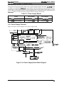
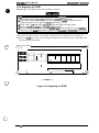
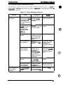
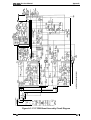
1.6.2 Main Control Board (C117 MAIN Board Assembly)
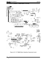
The C117 MAIN board assembly cxmsists ofi a TA4P96C14 8-bit CPU, an E05A87 gate array, a
PROM (2 megabit including the CG ROM), a PS-RAM (256K), an EEPROM, an SLA7026M for the
paper feed motor, an SLA5007 for the CR motor, each driver’s IC, and the parallel and serial
interface control circuits.
CN1O
g-lc;-$:,,RAM,
+
CN7
CN9
t
I-41,
1’
\
:
\
a
,1
IC1(CPU:TMPWC14)
0 nno
u
o &,-E,
~m :
i
I
zlJGJca+-I ~퀕°ÿ€•\•••üà€•œ•¥•pE•Œ`õ€•••¥•(•¥•€Ô¤
I
n
000
000
CN3
lC2fEEPROM 9SC46)
for +36V qotnn road)
tcqM51966
lC31PST5910 for IWC sptam mwt)
Db-witches
~ W? S,22,10,13,16,i4,16,20,21(dnv.r for PRINTHEAD)
L
Q28 031(dnvor for MOTOR, RF)
figure 1-28. C117 MAIN Board Assembly
1.6.3 Power Supply Circuit (C117 PSB/PSE Board Assembly)
The C117 PSB/PSE tmrd assembly power supply circuit supplies the control circuit and printer
mechanism drive circuit with power. The fan motor on this board keeps the temperature in the
lower case constant and cools the CR motor. The printer contains one of two power supply boards;
see Table 2-1 for irhrrnation on the input voltage and fuse ratings of your printer’s board.
~ T101 Trsnsformr
o
Clol
0101
,c. ,
s
..
RI
F1
r
f
z“
L.
CC3MPAMTER
o
~a?ol
T201
Ttansforrnsr
4- ml
k
\
‘%3
101
Figure 1-29. C117 PSWPSE Board Assembly
1-28
Rev. A
4
.,-
DFX-5000+ Service Manual
Product Description
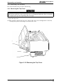
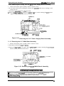
1.6.4 Control Panel Board (C117 PNL Board Assembly)
The C117 PNL board assembly is the operator control panel. It contains the buttons, indicator
LEDs, and buzzer.
9
10
5
RA1
Figure 1-30. C117 PNL Board Assembly
1.6.5 Housing
The housing consists of many parts. The lower case is the main frame which holds the printer
mechanism and circuits. These components are covered by the upper case, bottom plate, and two
side covers, each of which has various covers. The housing has large openings in the front and rear
for the paper entrances and exits. It also has a cover on the bottom plate to provide easy access to
the PROM on the main board.
——
c-)
‘\”
‘=”
\ ——
Figure 1-31. Housing
Rev. A
1-29
CHAPTER 2 Operating Principles
Table of Contents
2.1 OVERVIEW OF PRINTER MECHANISM OPERATION
2-1
2.1.1 Printhead Mechanism . . . . . . . . . . . . . . . . . . . . . . . . . . . . . . . . . . . . . . . 2-3
2.1.2 Carriage Mechanism . . . . . . . . . . . . . . . . . . . . . . . . . . . . . . . . . . . . . . . . 2-4
2.1.3 Platen Gap Adjustment Mechanism . . . . . . . . . . . . . . . . . . . . . . . . . . . . 2-5
2.1.4 Paper Feed Mechanism. . . . . . . . . . . . . . . . . . . . . . . . . . . . . . . . . . . . . . 2-6
2.1.4.1 Tractor Wire Operation . . . . . . . . . . . . . . . . . . . . . . . . . . . . . . . . 2-8
2.1.5 Ribbon Feed and Tractor Select Mechanism. . . . . . . . . . . . . . . . . . . . . . 2-9
2.1.6 Plunger Mechanism. . . . . . . . . . . . . . . . . . . . . . . . . . . . . . . . . . . . . . . . 2-11
2-12
2.2 POWER SUPPLY OPERATION
2.2.1 PowerSupplyOverview. . . . . . . . . . . . . . . . . . . . . . . . . . . . . . . . . . . . . 2-12
2.2.2 +5 VDCLine RegulatorCircuk. . . . . . . . . . . . . . . . . . . . . . . . . . . . . . . . 2-14
2.2.3 +35 VDCLine RegulatorCircuti. . . . . . . . . . . . . . . . . . . . . . . . . . . . . . . 2-15
2.2.4 +/-12 VDC Half-wave Rectifier Smoothing Circuit. . . . . . . . . . . . . . . . . 2-16
2-17
2.3 CONTROL CIRCUIT
2.3.1 Control Circuit Operation Overview. . . . . . . . . . . . . . . . . . . . . . . . . . . . 2-17
2.3.2 Reset Circuit . . . . . . . . . . . . . . . . . . . . . . . . . . . . . . . . . . . . . . . . . . . . . 2-21
2.3.3 Sensor Circuits . . . . . . . . . . . . . . . . . . . . . . . . . . . . . . . . . . . . . . . . . . . 2-Z
2.3.4 CR Motor Driver Cimufi. . . . . . . . . . . . . . . . . . . . . . . . . . . . . . . . . . . . . 2-25
2.3.5 PF Motor Driver Cimuit . . . . . . . . . . . . . . . . . . . . . . . . . . . . . . . . . . . . . 2-30
2.3.6 RF Motor Driver Circuit . . . . . . . . . . . . . . . . . . . . . . . . . . . . . . . . . . . . . 2-31
2.3.7 PG Motor Driver Circuit . . . . . . . . . . . . . . . . . . . . . . . . . . . . . . . . . . . . . 2-32
2.3.8 Plunger Driver Circuit. . . . . . . . . . . . . . . . . . . . . . . . . . . . . . . . . . . . . . . 2-33
2.3.9 Printhead Driver Circuit. . . . . . . . . . . . . . . . . . . . . . . . . . . . . . . . . . . . . 2-33
c)
62
-.” .,,
.-.
*..
List of Figures
Figure 2-1. Mode13Cll Printer Mechanism. . . . . . . . . . . . . . . . . . . . . . . . . . . . 2-1
Figure 2-2. Printer Mechanism Operation . . . . . . . . . . . . . . . . . . . . . . . . . . . . 2-2
Figure 2-3. Printer Mechanism Operation 2. . . . . . . . . . . . . . . . . . . . ........2-3
Figure 2-4. Printhead Operation. . . . . . . . . . . . . . . . . . . . . . . . . . . . . . . .. ....2-3
Figure 2-5. Carriage Mechanism . . . . . . . . . . . . . . . . . . . . . . . . . . . . . . .. ....2-4
Figure 2-6. Platen GapAdjustment Mechanism . . . . . . . . . . . . . . . . . . . . . . . . . 2-5
Figure 2-7. Tension Roller and PF Roller Operation . . . . . . . . . . . . . . . . . . . . . 2-6
Figure 2-8. Front Tractor Assembly Operation . . . . . . . . . . . . . . . . . . . . . . . . . . 2-7
Figure 2-9. RearTractorAssembly Operation . . . . . . . . . . . . . . . . . . . . . . . . . . 2-7
Figure 2-10. Tractor Wire Operation. . . . . . . . . . . . . . . . . . . . . . . . . . . . . . . . . . 2-8
Figure2-ll. Ribbon Feed Mechanism. . . . . . . . . . . . . . . . . . . . . . . . . . . . . . . . 2-9
Figure 2-12. TractorSelect Mechanism . . . . . . . . . . . . . . . . . . . . . . . . . . . . . . 2-10
Figure 2-13. Plunger Mechanism . . . . . . . . . . . . . . . . . . . . . . . . . . . . . . . . . . . 2-11
Figure 2-14. PowerSupplyBoard Block Diagram . . . . . . . . . . . . . . . . . . . . . . 2-12
Figure2-15. +5VDC Line RegulatorCircuit. . . . . . . . . . . . . . . . . . . . . . . . . . . 2-14
Figure2-16. +35VDC Line Regulator Circuit. . . . . . . . . . . . . . . . . . . . . . . . . . 2-15
Figure 2-17. Half-wave Rectifier Circuit . . . . . . . . . . . . . . . . . . . . . . . . . . . . . . 2-16
Figure 2-18. Control Circuit Block Diagram . . . . . . . . . . . . . . . . . . . . . . . . . . . 2-18
Figure2-19. Data Flow from the Parallel Interface . . . . . . . . . . . . . . . . . . . . . . 2-19
Figure2-20. Reset Circuit Block Diagram . . . . . . . . . . . . . . . . . . . . . . . . . . . . 2-21
Figure 2-21. SensorCircuit Block Diagram . . . . . . . . . . . . . . . . . . . . . . . . . . . 2-22
Figure 2-22. CRMotor Internal Circuit.. . . . . . . . . . . . . . . . . . . . . . . . . . . . . . 2-25
Figure 2-23. CR Motor Driver Block Diagram . . . . . . . . . . . . . . . . . . . . . . . . . . 2-25
Figure 2-24. Acceleration Control Cutve . . . . . . . . . . . . . . . . . . . . . . . . . . . . . 2-27
Figure 2-25. Deceleration Control Curve.... . . . . . . . . . . . . . . . . . . . . . . . . . 2-28
Figure 2-26. Measurement Sequence . . . . . . . . . . . . . . . . . . . . . . . . . . . . . . . 2-30
Figure 2-27. PFMotor Driver Circuit, . . . . . . . . . . . . . . . . . . . . . . . . . . . . . . . . 2-30
Figure 2-28. RF Motor Driver Circuit . . . . . . . . . . . . . . . . . . . . . . . . . . . . . . . . 2’31
Figure 2-29. PG Motor Driver Circuit . . . . . . . . . . . . . . . . . . . . . . . . . . . . . . . . 2-32
Figure 2-30. Plunger Driver Circuit., . . . . . . . . . . . . . . . . . . . . . . . . . . . . . . . . 2-33
Figure 2-31. Printhead DriverCircuit . . . . . . . . . . . . . . . . . . . . . . . . . . . . . . . . 2-34
List of Tables
Table 2-1 PowerSupplyBoards . . . . . . . . . . . . . . . . . . . . . . . . . . . . . . . . . . . 2-12
Table 2-2 DC Voltages . . . . . . . . . . . . . . . . . . . . . . . . . . . . . . . . . . . . . . . . . . 2-13
Table 2-3 Main IC Functions. . . . . . . . . . . . . . . . . . . . . . . . . . . . . . . . . . . . . . 2-20
Table 2-4. CR Motor Drive Modes . . . . . . . . . . . . . . . . . . . . . . . . . . . . . . . . . . 2-26
Table 2-5. CR Motor Drive Sequence . . . . . . . . . . . . . . . . . . . . . . . . . . . . . . . 2-27
Table 2-6. PF Motor Specifications . . . . . . . . . . . . . . . . . . . . . . . . . . . . . . . . . 2-31
Table 2-7. RF MotorSpecifications . . . . . . . . . . . . . . . . . . . . . . . . . . . . . . . . . 2-31
Table 2-8. PG MotorSpecifications . . . . . . . . . . . . . . . . . . . . . . . . . . . . . . . . . 2-32
Table 2-9. PlungerSwitching Pattern . . . . . . . . . . . . . . . . . . . . . . . . . . . . . . . 2-33
DFx-5tW(h Sewka Manual
Oparathg Prfncipka
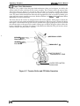
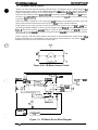
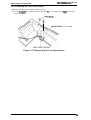
2.1 OVERVIEW OF PRINTER MECHANISM OPERATION
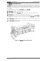
This section describes the Model 3C11 printer mechanism and explains how the printer works. The
Model 3C11 printer mechanism features a 9-pin, impact dot printhead for serial printing. The
printer mechanism is the main component of the printer and is supported by the other mmponents
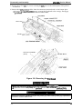
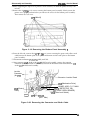
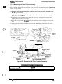
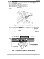
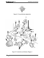
(the power supply and control arcuits). Figure 2-1 shows the Model 3C11 printer mechanism.
PAPER BA~L ASSEMBLY
Plunger
TIMING BEL
Connector
Junction
Board
TRACTOR ASSEMBLY (FRONT)
D MOTOR
\
PLATEN GAP ADJUSTMENT MOTOR
Figure 2-1. Model 3C11 Printer Mechanism
The printer mechanism consists of the following main components:
22 Printhead
The printhead is the component that actually pMts characters (dot matrix patterns). Printing is
performed by striking the pins (arranged in a vertical line) against the surface of the paper and the
ribbon. A character is printed by repeating this printing operation in the horizontal direction (as the
printhead moves). The printhead includes a head fan and temperature sensor. The head fan also
has a thermistor. When the printhead or fan is too hot, the printer stops printing until it cools.
(Refer to Section 1.4.12, Themud Probation.)
L1 Carnage mechanism
The carriage mechanism moves the printhead in the horizontal direction. The CR motor drives the
carriage, with the printhead on it. The CR sensor detects the CR motor speed and carriage position.
The CR motor is closed-loop controlled. Because the CR motor is driven at a very high speed, it
includes an isolation resistance sensor to detect abnormal resistance. The sensor detects an error if
the resistance is less than 1 I@.
Cl Interlock switch
Because the carnage moves at a very high speed, it would be dangerous if a hand or finger were
inserted inside the printer mechanism during printing. Therefore, as a safety measure, when the
top cover is opened, the interlock switch cuts the drive voltage to the CR motor to slow down the
carriage speed and prevent acadents. A control circuit controIs CR motor driver deceleration.
(Refer to Section 2.3.4., CR Motor Dine Circuit.) Printing resumes when the top cover is closed.
LI Auto platen gap adjustment mechanism
The printer mechanism has an automatic platen gap adjustment function that measures the
thickness of the paper and provides the appropriate gap between the platen and printhead. The
platen gap is adjusted by moving the carriage (and printhead) either forward or backward. Because
the front and rear carriage guide shafts which hold the @rriage are purposely mounted off-center,
the carriage moves as the PC motor rotates the shafts. The PG sensor transmits the amount of
movement (= gap) to the control circuit.
Rev. A
2-1
DFX-5000+ Service Manual
Operating Principles
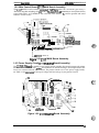
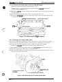
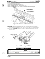
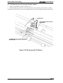
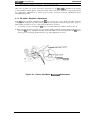
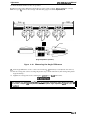
Cl Ribbon feed mechanism
The printer’s ribbon cartridge contains an endless ribbon. The ribbon feed mechanism takes up the
ribbon so that the portion hit by the pins is constantly changing. The RF motor drives the ribbon
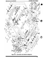
feed mechanism. Figures 2-2 and 2-3 show the operation of the ribbon feed mechanism.
SHAFT, CR, GUIDE, REAR
CARRIAGE
Inter Lock Switch
PLATEN GAP
PRINTHEAD
I
ADJUSTMENT MOTOR
L
MOTOR
,
&
6
,
II I
4
1
I
1,
I
I
[
I
I
I
I
I I I I 11
2JJJJU
/
I
\
I
9
Carriage Encoder Belt
Platen Gap Home Position
Sensor
DETECTOR, CR
Figure 2-2. Printer Mechanism Operation 1
Cl Paper feed mechanism
The CR motor controls printing in the horizontal direction, and the paper feed mechanism controls
movement in the vertical direction (line feeding and form feeding). The paper feed mechanism
feeds paper vertically. The PF motor drives the paper feed mechanism.
The front, rear, and top PE sensors detect whether paper is present in the paper path, and stop the
printer from printing when there is no paper. The printer is equipped with three PE sensors: the
front PE sensor at the front tractor, the rear PE sensor at the rear tractor, and the top PE sensor at
the paper bail. The pull tractor sensor detects whether the optional pull tractor is installed. The
printer is also equipped with a paper jam sensor. The control circuit reads the signals from the
sensors and indicates when an error occurs.
D Tractor select mechanism
The printer mechanism has two paper entrances: one at the front tractor and one at the rear tractor.
By controlling the RF motor, the txactor select mechanism chooses which tractor to use, and power
from the PF motor is conveyed via a series of gears. The tractor select sensor detects the selected
tractor and signals that information to the control circuit.
D Plunger mechanism
During printing, the paper bail assembly holds the paper under tension so that it is fed smoothly.
When paper is loaded or ejected or when the tear off function is executed, the paper bail assembly
needs to move up to prevent a paper jam. The plunger moves the paper bail assembly up. Figure
2-3 shows this operation.
2-2
Rev. A
DEX-4XXW Service Manual
Opating Princ@ha
Paper
TRACTOR ASSY., PULL
\.fi(
SENSOR ASSY., PE, UPPER
PRINTHEAD
- S E N S O R ASSY., P A P E R
JAM
TRASCOTR SELECT SENSOR
SENSOR ASSY., PE, REAR
SENSOR ASSY.,
PE, FRONT
Rear Tractor Sprocket
Front Tractor
Sprocket
PAPER FEED MOTOR
RIBBON FEED MOTOR
Figure 2-3. Printer Mechanism Operation 2
2.1.1 Printhead Mechanism
The printhead is a charge-type, impact dot pnnthead. 13gure 24 shows its operation. The dot wire
is attached to the actuating spring at point A. It is pulled back (left in the figure) by magnetic form
when power is applied and during standby. The magnetic force holds back the actuating spring.
When current flows through the coil, a countermagnetic field is rnduced in the coil. Then, the
actuating spring ejects the dot wire fix-ward against the ink ribbcm, printing a dot on the paper.
,c.
. . ‘1
:..,’;
+35VDCo
GNDo
MASK HOLDER (Cutting)
/
/
PLATEN ASSY.
A
/
. . . -——J./
: —
——\\
LJ
-+
/ / / / /
Iron Core
A
Head Drive Coil
....,
(J
Ribbon
Figure 24 Printhead Operation
Rev. A
2-3
DFX4000+ Service Manual
Operating Principles
2.1.2 Carriage Mechanism
Figure 2-5 shows the carriage mechanism. The front and rear carriage guide shafts support the
carriage. The rotation of the CR motor is transmitted to the carnage timing belt through the
carriage belt pulleys at the right and left sides. The printhead is mounted on the carriage, which is
attached to the carriage timing belt and moves horizontally.
The printer does not have a carriage home position sensor; the home position is detected using
disordered pulses of the CR motor and CR sensor (linear, belt-type). A gum pad is attached to the
left side of the frame. When the carriage hits the pad, the CR motor pulse is disordered by this
obstacle. The control circuit monitors the CR motor’s pulse; when it is disordered, the control
circuit recognizes the carriage home position.
The CR motor is equipped with an encoder unit which generates pulses. The encoder belt has
equally pitched slits and is mounted under the timing belt. A photo interrupter (encoder)
surrounds the encoder belt and converts the carriage movement into a pulse train.
HEAD DAMPER (LEFT) .
SHAFT, CR, GUIDE, FRONT /
-’&ZZ.=
Carriage Encoder Belt TIMING B~} CR~
9
Figure 2-5. Carriage Mechanism
2-4
Rev. A
Oparathg Prlnclpks
DEX-5Uk Servic@ Man(ml
2.1.3 Platen Gap Adjustment Mechanism
Figure 2-6 shows the platen gap adjustment mechanism. The front and rear carriage guide shafts
supporting the carriage have a vertical wtion. The rotation of the PG motor is transmitted to the
rear carriage guide shaft through the gears. Counterclockwise rotation of the motor expands the
platen gap and clockwise rotation reduces it.
The encoder plate with equally pitched slits is attached coaxially to the motor axis. When the motor
rotates, the PG sensor detects it and outputs the pulses. Each pulse corresponds to detection of a
0.015 mm resolution (horizontal distance). The system range is O to 0.7 mm.
‘:ENASSEMBL%23P.-’.
Mask less Holder
SHAFT, CR, GUIDE, REAR
PLATEN
ON GEAR
NSOR
AJ’”
Platen Gap Encoder Plate
PLATEN GAP
ADJUSTMENT MOTOR
*
c=
Cw
Ccw
Figure 2-6. Platen Gap Adjustment Mechanism
f--”
J
Rev. A
24
DFX-5000+ Service Manual
Operating Principles
2.1.4 Paper Feed Mechanism
Figures 2-7, 2-8, and 2-9 show the paper feed mechanism. After you load paper, it is fed by the
tension roller, PF roller, and front or rear tractor assembly. The PF motor rotates the tension roller
and tractor select gear (Figure 2-7) and moves either the front or rear tractor assembly. The rotation
of the paper feed transmission gear rotates the tractor select gear, which can engage either tractor
train. The tractor select mechanism alternates the engagement of the rear tractor assembly gear
train and front tractor assembly gear train. (Refer to Section 2.1.5, Ribbon Feed and Tractor Select
Mechanisms, for more information.)
The front and rear PE sensors are incorporated in the tractor sprocket. When paper is loaded, the
paper pushes the leaf spring and blocks the photo interrupter. When no paper is loaded, the photo
interrupter is not blocked. The top PE sensor is attached to the upper paper guide and is used with
the reflection plate on the paper bail assembly. When paper is loaded, the paper surface reflects the
beam; when there is no paper, the beam is absorbed (not reflected). The pull tractor sensor
monitors whether the pull tractor is installed.
APER BAIL LEVER
SENSOR ASSY.,
TRACTOR
SENSOR ASSY.,
PE, UPPER
TIMING BELT, PF
M–
“)
TRACTOR SELECT
TRANSMISSION GEAR
~D \, ,
ol~l
‘KG
-1’ . .
1
(’( @=-4/
w
PAPER FEED MOTOR
Pinicon Gear
Figure 2-7. Tension Roller and PF Roller Operation
24
Rev. A
Paper
PAPER BAIL LEVER
TENSION ROLLER
TRACTOR SELECT
TRANSMISSION GEAR
SENSOR ASSY., PE, FRONT
Tractor Sprocket (Front)
PAPER FEED MOTOR
Pinion Gear
Figure 2-8. Front Tractor Assembly Operation
\
, Paper
PAPER BAIL LEVER
TENSION ROLLER
..
SENSOR ASSY., PE, FRONT ~ \ TRACTOR SELECT GEAR
I
k-i-l U.!!xtw” /1
Tractor Sprocket (Rear) ~’”~y
t@j-)@;E: FEED MOTOR
Figure 2-9. Rear Tractor Assembiy Operation
Rev. A
2-7
Operating Principles
DFX-5000+ Service Manual
2.1.4.1 Tractor Wire Operation
The printer is equipped with a tractor wire (white line) to prevent paper jams when continuous
paper is loaded from the front or rear entrance. The tractor tension spring on the right side frame
pulls the wire and releases the stress on the continuous paper being fed. Figure 2-10 shows how the
tractor wire operates.
The front left tractor sprocket or rear right tractor sprocket is fixed in position by the shape of the
bottom frame of the printer mechanism, while the other sprocket (the front right sprocket or rear
left sprocket) can move along the tractor shafts. When the tractor release lever is released, the
sprocket can move smoothly side to side along the tractor shafts. When the tractor release lever is
engaged, the sprocket can move along the tractor shafts, but it cannot move smoothly, because the
tractor wire tension is valid.
In the Figure 2-10, point A shows the movement range of the left tractor sprocket when the tractor
release lever is released. Point B shows the movement range of the right tractor sprocket when the
release lever is engaged or released.
If the paper in the printer becomes bubbled, you can pull the tractor wire to the right to stabilize
the paper tension between the left and right tractor sprockets.
nsion
-1
A
—
.
B
>
Tractor Wire
Tension Spring
(In case of Front Entrance)
Figure 2-10. Tractor Wire Operation
24
Rev. A
DEX-5000+ Service Manual
operating #%’fnclphe
2.1.5 Ribbon Feed and Tractor Select Mechanisms
.J&
,,
@
The RF motor supplies power to both the ribbon feed and tractor select mechanisms. The rotaticm
of the RF motor pinion swings the ribbon feed select gear like a pendulum, using the lever axis as a
support point. The rotation of the RF motor is transmitted after the gears are engaged. When the RF
motor pinion gear rotates counterclockwise, the motor rotates the ribbon feed mechanism; when it
rotates clockwise, the motor rotates the tractor select mechanism.
Figure 2-11 shows the ribbon feed mechanism. 7he ribbon is fed in only one direction.
Counterclockwise rotatkm of the RF motor is transmitted to the ribbon feed gear through the
ribbon &d select gear and ribbon feed transmission gear. The ribbon feed gear engages the
winding roller on the ribbon cartridge to feed the ribbon.
Iv
RIBBON
GEAR
N GEAR
Figure 2-11. Ribbon Feed Mechanism
0
;?5
.. .
Rev. A
24
DFX4000+ Service Manual
Operating Principles
Figure 2-12 shows the operation of the tractor select mechanism. Clockwise rotation of the RF
motor is transmitted to the tractor select cam through the ribbon feed select gear and tractor select
transmission gear, and rotates the tractor select cam clockwise. The tractor select lever contacts the
inside curve of the cam due to the spring force; when the cam rotates, the tractor select lever moves
horizontally along the curve.
When the tractor select lever is set to the left, the tractor select gear engages the rear tractor
assembly train, and the PF motor rotates the rear tractor assembly. When the tractor select lever is
set to the right, the tractor select gear engages the front tractor assembly. The tractor select sensor
contacts the cam and closes when it reaches the convex portion.
TRACTOR DRIVE
GEAR
---1
*EI*
—TRACTOR SELECT
TRANSMISSION GEAR
TRACTOR SELECT GEAR
HOLDER
–TRACTOR SELECT
LEVER LOWER
-TRACTOR SELECT
LEVER UPPER
TRACTOR SELECT
SENSOR
-TRACTOR SELECT CAM
[
RIBBON FEED SELECT=
GEAR
,
RIBBON FEED MOTOR~
\
Figure 2-12. Tractor Select Mechanism
2-1o
Rev. A
Operating Prfnc@laa
DFX-5LXXI+ Service Manual
2.1.6 Plunger Mechanism
Figure 2-13 shows the plunger mechanism. The paper bail assembly is attached to the tmd of the
plunger’s iron core. The paper bail assembly axis is connected to the frame. When the plunger coil
is energized, the force of the paper bail spring returns the paper bail assembly to ik original
position.
PAPER BAIL LEVER
I
I
\’
Figure 2-13. Plunger Mechanism
0.,
Rev. A
2-11
DEW5000+ Service Manual
Omratinf7 Principles
2.2 POWER SUPPLY OPERATION
The printer can be powered by either of two power supply boards: the 120 V C117 PSB board
assembly or the 220/240 V PSE C117 board assembly. The only difference in the operation of these
two boards is in the primary circuitry. They supply power to the printer in the same way. The
power supply board outputs the DC current required to drive the control circuits and printer drive
mechanis-rn. Table 2-1 shows the input voltages and fuse ratings of the boards.
Table 2-1. Power Supply Boards
Input Voltage
Fuse Ratings
Cl 17 PSB board assembly
100-120 VAC
6.3 A1250 VAC
Cl 17 PSE board assembly
220-240 VAC
12 A/125 VAC
Board
2.2.1 Power Supply Overview
Figure 2-14 shows a block diagram of the power supply board.
Surga-cut
—
— Recfifiar
Circuil
—
a
Smoothing
circuit
circuit
o
~
1
r
t}
a
Main swhching
Circuit (1)
Smoothing
Circuit
a
a
‘+’”
&
VPC signal
t
rll
Main swtching
Circuit (2)
Transfosrmar
a
T
+3SV Drop rnontor
Circuil
A
—
DRERR S@’ld
)+
r
Smoothing
Circuit
)
)
\ .
J
O +3SV or 13V
O GP
~ CLIMIT
signal
+3SV Over vdtqa
Protection Circuil
Figure 2-14. Power Supply Board Block Diagram
2-12
Rev. A
DFX-5000+ Sendee Mama!
e
O~atfng Princi@aa
The power supply board converts the AC voltage to the DC voltages required to operate the
printer. The AC voltage is input to the AC inlet, and is supplied to the C117 power supply board
assembly via the power switch and fuse. l’hree switching regulator circuits convert the AC voltage
to the three DC voltages (+35 V, +5 V, and +/-12 V) required to operate the printer.
The power supply board contains two +35 VDC creation circuits. (Ike +35 VDC line is divided into
two sections.) One +35 VDC line supplies power to six of the nine printhead pins (pins 1,3,5, 7,8,
and 9); the other +35 VDC line supplies power to three of the nine printhead pins (pins 2,4, and 6)
and to the motors.
These switching regulator circuits perform voltage control and over-current limiting for each
voltage. They supply or cut the DC voltage based on the DRERR (Driver Error) signal from the
C117 MAIN board assembly, and output the CLIMIT (Power Down) signal when the printer has
exceeded its duty cycle (the printhead temperature is too high).
The Cl17 power supply board assembly includes a cooling km that is driven by the +35 VDC. The
fan lowers the temperature of the circuit components, and is located under the carnage motor so
that it also lowers the carriage motor temperature.
To prevent a surge in the current, the power supply board cannot recover for approximately thee
minutes after the power is turned off. Therefore, after the printer is turned off, wait three minutes
before you turn it back on.
m
%i;’
The specifications for the C117 power supply board assembly depend on the board type (120 V
C117 MB or 220/240 V C117 PSE).
Before using a different AC power supply, replace the fuse and power cord.
Table 2-2. DC Voltages
Voltage
Rated Current
Application
+35 V (CN2)
2A
Q Printhead drive
Q CR motor drive
Q PF motor drive
Q PG motor drive
Q RF motor drive
Q Plunger drive
Q Head fan motor drive
+35 V (CN4)
2A
Cl Fan power for coding the CR motor
+5 V (CN3)
1.0 A
O All Iogio systems (Cl 17 MAIN board
assembly and Cl 17 PNL bad ~w
operating voltages)
Q CR motor hold voltage
Cl ~U~W hold vda~
Q i% motor hold voltage
0 Power for ail the sensors
+12 V (CN3)
0.1 A
Cl Cl 17 MAIN board assembly operating
voltage (serial interface conversion and
Type B optional interface voltage supply)
-12 V (CN3)
0.1 A
D F~ trigger for printhead firing
Note:
Before the power supply board outputs +35 VDC, it outputs +13 VDC to the printhead
drivers on the C117 MAIN board assembly. ‘This procedure is a driver check to prevent
printhead damage.
,c),.: *Rev. A
2-13
DFX-5000+ Service Manual
Operating Principles
2.2.2 +5 VDC Line Regulator Circuit
The +5 VDC line regulator circuit uses a ringing choke coil (RCC) system DC/DC converter.
+35VIX
-
b
A
IC151
(TL494)
C2
C,, I’.,.
+3VUL,
)-P
cl
1
+11
+12
-
Zk
ZD153
HZS7B-2
PRIMERY CIRCUIT
Figure 2-15. +5 VDC Line Regulator Circuit
The rectified and smoothed DC voltage turns on the +5 VDC line first. RIM is a starting resistor.
When the +35 VDC line becomes +13 V, switching regulator IC TL494 (IC151) creates a +5 V line.
The power supply board uses a 2-step rise method. When the printer is turned on, the +35 VDC
line outputs +13 VDC for 140 ms. The first rising voltage (+13 VDC) is used to check the printhead
drivers on the C117 MAIN board assembly.
If a printhead driver is damaged, the control board outputs the error signal (HIGH DRERR signal)
to the power supply board. When the power supply board receives this signal, the photo-coupler is
turned on and it cuts off the voltage of the primary side. This prevents printhead damage when a
printhead driver is damaged. If the printhead drivers are normal, the control board outputs the
VPC signal to the power supply board. When the power supply board receives this signal, the line
rises to +35 VDC after 140 ms.
me +5 VDC regulator circuit includes the following:
D +5 VDC line over-voltage protection circuit
If the +5 VDC line exceeds +7 VDC, the current flows to ZD153. Then Q155 is turned on, the
phot~coupler (PC2) is turned on, and the voltage of the primary side is cut off. This circuit is a
common circuit with the DRERR signal feedback circuit on the C117 MAIN board assembly.
D +5 VDC line over-voltage control/over-current control circuit
IC151 (TL494) includes this control circuit. IC151 contains two internal comparators. One
comparator is used for over-voltage control. Pin 16 (+12) monitors the +5 VDC line. If this voltage
exceeds +5 V (pin 15), internal comparator 1 outputs a HIGH signal. The other comparator controls
the +5 V Iine over-current. Pin 1 (+11) monitors the current of the +5 V line. If the current exceeds
the set value (pin 2), the voltage becomes HIGH and comparator 2 outputs a HIGH signal.
Both the comparator 1 signal and comparator 2 signal are tied by the wired OR. If the output signal
is HIGH from either comparator, the output signal is HIGH. This switching procedure monitors the
Cl and C2 ports. These switching waveforms are controlled by PWM (Pulse Width Modulation),
which changes the level of the inverse terminal of comparator 1 and comparator 2.
Cl Printhead driver detection circuit
This circuit prevents printhead damage when a printhead driver is damaged. When the printer is
turned on, the C117 MAIN board assembly tells the C117 power supply board assembly whether
the printhead drivers are normal.
If a printhead driver is damaged, the C117 MAIN board assembly sends the DRERR signal to the
C117 power supply board assembly. When the C117 power supply board assembly receives this
signal, it stops creating +35 VDC and +5 VDC. If the printhead drivers are normal, the C117 MAIN
board assembIy sends the VPC signal to the C117 power supply board assembly. When the C117
power supply board assembly receives this signal, it creates +35 VDC.
2-14
Rev. A
operating Principbe
DFX-5000+ Service Manual
2.2.3 +35 VDC Line Regulator Circuit
When the printer is turned on and the C117 MAIN board assembly sends the WC signal, the +35
VDC line rises from +13 V to +35 V. The +35 VDC line arcuit uses a ringing choke mnvertor (RCC)
AC input switching power circuit. This system uses few parts and a small transformer, and is ok
used when a small power supply is required.
Figure 2-16 shows the +35 VDC line main switching circuit. When power is applied, drive current
flows to the gate of switching FET (Q101) via starting resistor R118. Diodes D157, D156, D151, and
D251 on the secondary side of T1 and T2 prevent current flow in the secondary side. When QIOl is
turned on, the primary side of transformer coil T2-3 receives an rnput voltage, which induces
voltage in windings W-4 and ‘12-3. When Q101 is turned off, the currmt flows to the wamdary
side of the transformer coil.
o
Filter Clrcuk
R9ctifbr
Circuit
arcuit
H
o
, p:. ,
(“
Surge-cul
H
“
smoothing
C&wit
H
I
h
Main sWching
Circuif (1)
Smmthing
Clrcuif
Over Current
Protection
Circuit (IC101,2O1)
a
--0 +35 VDc
a
a
O GP
+/-13 v Creatial
(ZD151,181 / ZD1S2-1S5)
Main switching
Transformer
Smcdhing
Cimllit
0- WC Sigrui
0
a
+35 WC Drop Monitor
ckcuii (NJM2903)
- OREFIRS@d
--
0 +35 VDc
o
GP
O ~ CI.MT signal
+35V O/er Volmga
Prokxiorl Ck4it
(91s3,0353)
Figure 2-16. +35 VDC Line Regulator Circuit
. . .{
..c’
...
c
T
al%
“:.>..
)
Rev. A
2-15
Dl%Y4iOOO+ Service Manual
Operating Principles
The +35 VDC regulator circuit includes the following:
D Input voltage line over-current protection arcuit (primary side)
IC101 and IC201 detect the input voltage of the primary circuit. When the input voltage is normal,
the current does not flow into the shunt regulator. When the over-current flows to the input
voltage line, the shunt regulator is turned on, Q103 (Q203) and Q102 (Q202) are turned on, and
Q101 (Q201) is turned off.
Q +35 VDC line over-current protection circuit
If the +35 VDC line drops to +13 VDC, the sensor circuit consisting of R172 (R272) and R173 (R273)
turns on Q153 (Q253). Q154 is turned on, PC2 is turned on, and then the input voltage is cut. At this
time, the delay timing creation circuit (CR circuit) consisting of C157 and R174 makes the delay
timing. When the printer is turned on, the delay timing creation circuit cannot start this protection
circuit; if it is operated during the printhead driver check, the power supply board cannot be
turned on. The CR circuit has approximately a one-second delay timing.
Cl +35 VDC powerdown detection circuit
When the +35 VDC line drops (such as, when the printer has exceeded its duty cycle and the
printhead temperature is too high), the voltage of PC101 approaches O VDC. If the voltage drops to
1.3 VDC, IC152 outputs a HIGH CLIMIT signal to the base of transistor Q187. IC152 monitors the
two +35 VDC line creation circuits.
Cl +13 VDC creation circuit
When the printer is turned on, the C117 power supply board assembly creates +13 VDC to check
the printhead drivers on the C117 MAIN board assembly. After 140 ms, the C117 MAIN board
assembly sends the DRERR (driver error) or the VPC (+35 VDC permission) signal to the C117
power supply board assembly. If the printhead drivers are normal, the VPC signal is HIGH, Q182
is turned on, and Q181 is turned off. Therefore, six Zener diodes create the +35 VDC. During the
motor driver check, the VPC signal is LOW. When this signal is LOW, Q182 stays off, the base of
Q182 stays HIGH, and then two Zener diodes (ZD151 and ZD181) output +13 VDC.
2.2.4 +/-12 VDC Half-wave Rectifier Smoothing Circuit
The power from the half-wave rectifier smoothing circuit is mainly supplied to the RS-232C
interface on the standard or optional board and uses the printhead fire trigger. Both the +12 VDC
and -12 VDC lines have a half-wave rectifier circuit. This smoothing circuit consists of capacitors
C182 and C181. Two Zener diodes stabilize the *12 VDC line.
o
FMer Circuit
o
surge-cut
Circuit
Rectifier
Circuit
Smoothing
C+ Icuit
I
I
J
4)
“~
-12VDC Cteation
TF –:==
Smoothing Circuit
(C181,182)
Main switching
Circuit (1)
Over Current
Protection
Cimuif (ICI01,201)
I
+
Transfmxmer
+
=
DerM3dvoltage
Conttd arcut
ZD187,1SS
❑
ci!:~=l~)
+12VDC Creation
Circut
(QIS3,184)
Smoothing Circuit
(C1SA3,161)
o +12 VDC
o -12 WC
+
Figure 2-17. Half-wave Rectifier Circuit
2-16
Rev. A
DEX-5000+ Servics Manual
@wating *“ncipba
2.3 CONTROL CIRCUIT
Figure 2-18 shows a block diagram of the control arcuit with the C117 MAIN board assembly at the
center.
2.3.1 Control Circuit Operation Overview
The core of the control circuit is the TMP96C14 CPU (IC1). This CPU is driven using a 14.74 MHz
external clock (CRU1). The CPU executes programs stored in the internal mask ROM and IM
external PROM (IC4). The CPU starts executing a program upon r-iving the reset signal from an
external device (IC8, IC9). The CPU accesses the internal RAM and external P$RAM (256K)
memories. The CPU also contTols the non-volatile memory (IC2) used to store the parameters, such
as the tear off position, while the printer is turned off. The CPU controls all the printer operations
via the peripheral ICS and controls the printer mechanism and interfaces by writing directly to the
ports. The CPU controls the E05A87 gate array (IC7) via the address bus (MMIO: Memory Mapped
Input/Output).
c\. ,. %
~....,
The main functions of the E05A87 gate array are: ~ (Chip Select) signal creation, address
decodina printhead driver control, carriage driver control, encoder pulse arcuit control, PG and
fan motor phase signal creation, interface control, CR and PF motor driver abnormal sensor arcuit
control, reset signal creation, control signal creation for the power supply board, control of the
LEDs on the Cl 17 PNL board assembly, and reading the DIP switch settings.
L,,,,
Signals, such as DRERR, VPC, and CLIMIT (power down), are comected to the C117 power supply
board assembly to provide back-up control of the non-volatile memory (when the printer is turned
off) and control of the power supply voltage. When the CLJMIT signal informs the CPU that the
power has been turned off (or that the power supply voltage has dropped), the CPU turns off the
power supply voltage from the C117 power supply board assembly by outputting the CLIMIT
signal.
The reset circuit outputs the reset signal when the printer is turned on or off, the voltage level
drops, or a reset signal is input from an external device. It resets the control circuit for a certain
period directly or via the E05A87 gate array.
...
L
Rev. A
2-17
DEX4000+ Service Manual
Operating Principles
CPU
TM P96CI 41
(lCl)
P-ROM
(IC4)
-’l
-’i
Q28 - Q31
I
1
MOTOR, RF
t-1
1
SLA7026M
(Icll)
t-
MOTOR, PF
,
I
m
m
L
Each Sensors Circuit
1.PE(top) 2. PE(front) 3. PE(rear)
4. Paper Jam 5.PG Home position
6.PuII Tractor 7. Tractor Select
8. Cover Open 9. Paper Wide
10.Fan Temperature
11 .MOTOR, CR isolation
12. Head Temperature
13.MOTOR,PF Watch Dog Timer
14.Drop Error Signal Detection
(from BOARD ASSEMBLY, C117PS)
~ Address Bus
= Data Bus
1
I
FAN
-1
SDC03(QM2)
P
Q17,Q18
MOTOR,PG
PLUNGER
ZICR
A
Interlock
itch
L
I
Standard/Optional
Interface
I
1
Q26,22,10,13,16,
- 14,18,20,21
------+ PRINTHEAD
1
I
I Each Sensors Circuit
BOARD ASSEMBLY,
Cl 17 PNL
k
1
I
1.PG encorder sensor
2.CR encorder sensor
3. PRINTHEAD thermistor sensor
Figure 2-18. Control Circuit Block Diagram
2-18
Rev. A
DFX-5000+ Servics Mimml
0per8thg Ffinchl&e
Figure 2-19 shows the data flow for data input via the parallel interface. Although various circuits
perform data processing, the control core is the CPU and all operations are executed via the CPU.
In this circuit, the gate array IC (IC7) provides the interface between the external heat computer
and the CPU, and all data processing is performed by read/write operations to MMIO (Memory
Mapped Input/Output).
Data from the host computer is latched by repeating steps 1 through 3 below.
1. Upon receiving the STROBE signal, IC7 latches the data into ports DIOO - 7and sets the BUSY
signal to HIGH.
2. The CPU reads the latched data from the MMIO pcx% checks whether the data is a print
command (CR code), and stores it in the input data buffer if it is not.
3. After checking the data, the CPU makes IC7 clear the BUSY signal and output the ACKNLG
signal, via the MMIO accesses. When either a CR code is received or the input data buffer
becomes full, the CPU sets the BUSY signal to HIGH and executes printing.
E05A87 (IC7)
STROBE
a,.:
$
DATA
BUSY or IACK
m
w
PS-RAM (IC3)
CPU (ICI)
Input Data
2
1
40
o
Buffer
..
0
.................
Buffer Full.
.: DATA
CR command ?
DATA
Yes
,..
-: + e ‘)o
Yes
L
..+--------- . . . . . . . . . . . . . .
+r-,
‘*A
I
.. ........
d
elI
‘u(lCl)
4
Command
Analyzer
AHribute
T
Printer Mechanism
Driver
+
Character Generator
................
I
Down Load ““;
Image Buffer
I
I
?1
o8
I
Figure 2-19. D8tti flow from the Parallel Interface
4. The CP[J reads the data from the input data buftkr, analyzes eacii byte to determine whether it
is a character or a coremand, and converts it to print data. The print data consists of l-byte
character codes and 2-byte attributes. Character data is stored as character codes and
commands or character types are stored as attributes.
Rev. A
2-19
DEX4000+ Service Manual
Operating Principles
5. The print data is stored in the line buffer in units of one line of data.
6. The CPU reads the print data stored in the line buffer byte by byte, accesses the CG (Character
Generator), and expands the data in the image buffer (in the case of download characters, in
the download CG). A row of expanded data is output to the printhead control circuit as head
data.
7. When data is expanded to an italic or super/subscript character, the CPU uses IC7 to expand it
via MMIO.
8. The CPU controls the CR motor by calculating the control data for each line from the print data
in the line buffer. When a paper feed command is sent after one line is printed, the CPU
executes paper feeding.
For NLQ characters, printing one line consists of two passes; the printer performs steps 6 through 8
twice. When the CPU expands the data from the CG in the image buffer, it uses the 24-bit shift
register in IC7. The CPU is always ready to fetch data so printing can be viewed as an
interrupt-to-fetch operation. Whenever the input data buffer is not full between printing
operations, data is fetched. Table 2-3 describes the functions of the main printer components.
Note:
The data flow from the serial interface is the same as the data flow from the parallel
interface, described above, except the signal names and data access method differ.
Table 2-3. Main IC Functions
IC Name
Location
Functions
TMP96C141
Icl
Receives data from the host computer via the gate array,
loads the data to the input buffer in PS-RAM, and converts the
image data to print data.
E05A87
IC7
Th&main E05A87 features are:
Q CS (Chip Select) signal creation
D Address decoding
Q Address latching
Cl Clock pulse creation (divided from the CPU clock)
Q Printhead driver control
D CR motor driver control
LI CR and PG motor pulse encoder l/O (input/output)
Q Encoder pulse 1/0
Q Phase signal creation for the motors
Q i/O port control
Q Interface control
Q Abnormal CR and PF motor detection
Q RESET signal creation
Q Control signal creation for the power supply board PROM
PROM
IC4
Contains the program that runs the CPU.
PS-RAM
IC3
Holds the CPU working area and buffers
(input, line, and image buffers).
SLA7026
ICI 1
Drives the RF motor and controls the constant current.
SDC03
QM2
Drives the PG motor.
NJM2903
Iclo
Detects the current in the CR motor driver and feeds it back to
the gate away.
SLA5007
QM1
Drives the CR motor.
(CPU)
2-20
Rev. A
Optuating Prfncipka
OEX-5000+ %rvica hfimual
2.3.2 Reset Circuit
This section describes the hardware reset circuit. When the hardware reset signal is input, all ICS in
the control circuit are reset, and the CPU executes the program from the starting address. Figure
2-20 shows the reset arcuit block diagram.
The printer is equipped with two reset ICS: PTS591D is used for resetting the + 5 VDC line and
M51955 is used for resetting the +35 VDC line. These reset ICS are described below.
Cl +5 VDC reset arcuit
Reset IC PTS591D monitors the +5 VDC line on the C117 MAIN board assembly. If it drops to 42
VDC, the reset IC outputs a LOW signal to the CPU, gate array, and optional interface board. l’he
gate array outputs the RESET signal to the reset port of the CPU and also to the gate array itself, via
the delay control arcuit (CR circuit). The delay cxmtrol circuit cmsists of R26 and C72 and controis
the reset timing for the CPU and Type B interface card.
Cl +35 VDC reset circuit
Reset IC M51955 monitors the +35 VDC line. Normally, the dividing resistors (R27 and R28) input
approximately 1.7 VDC to pin 2. When the detection level is 1.7 VDC, the +35 VDC line drops into
the 22.9 V to 30.0 V range.
If this voltage level drops to +125 VDC, the RESET signal (LOW level) is output to the CPU’s NMI
port. When the printer is turned off, this circuit operates and manages writing to the EEPROM.
R2a
r!-r Cn
I
R2S
21
777-
i
n mEsin
2’ INMI
I
CPU
TMP96C141 (ICI)
Figure 2-20. Reset Circuit Biock Diagram
i
.-
Rev. A
2-21
DFX-5000+ Service Manual
Operating Principles
2.3.3 Sensor Circuits
Figure 2-21 shows the sensor circuits in block diagram form. The printer is equipped with the
following sensors:
1.
2.
3.
4.
5.
6.
7.
8.
9.
10.
11
12.
13.
14.
Front and rear PE sensors (use a photo interrupter)
Top PE sensor (to detect the TOF position, uses a photo interrupter)
Paper jam sensor (uses a magnetic transistor)
Tractor select sensor (uses a micro mechanical switch)
Pull tractor sensor (uses a micro mechanical switch)
Cover open sensor (uses a micro mechanical switch)
CR encoder sensor (uses an LED and photo diode)
PG sensor (uses a photo interrupter)
PG home sensor (uses a micro mechanical switch)
+35 VDC voltage drop sensor (signal interface)
Head temperature sensor (uses a thermistor)
Fan temperature sensor (uses a thermistor)
PW sensor (uses a photo reflector)
Carriage motor isolation resistance sensor (monitored by the analog port of the CPU)
CPU
TMP96C141 (lCl)
>>>
Z
I
47
68
67
65
48. 50,
32,
51
72
71
(
LJ
T
84
18
z
v
-
76
75
74
26,
3<
19/
z
0
73
1
n
-3
n
)
3
Figure 2-21. Sensor Circuit Block Diagram
2-22
Rev. A
DEX-5000+ Setvice Manual
C)pmWng Pn”nc@&a
Each sensor is described below.
1. Front and rear paper end sensors
Photo interrupter
L1 Detection form:
Open collector (pulled up to 10 Kfi2 resistance)
Q output form:
CR filter circuit (10 Kfil and 39 pF)
LI Input circuit:
Paper present: LOW
Cl Logical:
Paper out: HIGH
2. Top paper end sensor (to detcd the TOF position)
Photo reflector
Cl &?te&ion form:
Open collector
c1 output form:
CR filter circuit (10 Kf2 and 39 pF)
Cl Input circuit:
Paper present LOW
0 Logical:
Paper out: HIGH
3. Paper jam sensor
~ Detection form:
c1 output form:
D Input arcuit:
Ct Logical:
LI Supplement:
Magnetic transistor
Rectangle wave (1 channel, TTL level)
Resistance for latch up prevention (10 KQ)
Paper feed: Level changes continuously.
Paper jam: Level remains the same.
The magnetic transistor is attached to the tension roller on the paper tension
unit.
4. Tractor select sensor
Micro mechanical switch
D Detection tirm:
Resistance for latch up prevention (10 Kf2 )
Cl Input circuit:
Pulled up to 390 f2 resistance
Front tractor: LOW (closed)
a Logical:
Rear tractor: HIGH (open)
5. Pull tractor sensor
Lt Detection form:
Ct Input arcuit:
L1 Logical:
6. Cover open sensor
O Detection firm:
Q Input arcuit:
u Logical:
Micro mechanical switch
Resistance for latch up prevention (10 I@)
Pulled up to 390 f2 resistance
Pull tractor installed: LOW (closed)
Pull tractor not installed: HIGH (open)
Micro mechanical switch
CR filter arcuit (10 KQ and 0.01 I@
Pulled up to 390 Q resistance
Cover closed: LOW
Cover open: HIGH
7. Carnage
encoder sensor
LED and photo diode
Cl Detection form:
Rectangle wave (2-phase, Tll level)
Ct Input arcuit:
CR filter arcuit (10 Kf2 and 390 pF)
Pulled up to 10 Kf2 resistance
The carriage encoder outputs two pulses (A or B) to the gate array and the
LI Transaction:
gate array tells the CPU which signal it receives.
Rev. A
2-23
DFX-5000+ Service Manual
Operating Principles
8. Paper thickness sensor
D Detection form:
Cl Input circuit:
Cl PG ability:
D Sensing range:
Photo interrupter
Rectangle wave (2 channels, TTL level)
CR filter circuit (10 KQ and 390 pF)
0.015 mm/pulse
O to 0.7 mm
9. Platen gap home position sensor
D Detection form:
Ct Input circuit:
Micro mechanical switch
Resistance for latch up prevention (10 KCt)
Pulled up to 390 ~ resistance
10. +35 VDC voltage drop sensor (signal interface)
When the +35 VDC line voltages drop, the C117 power supply board assembly sends a HIGH
CLIMIT signal to the C117 MAIN board assembly.
11. Head temperature sensor (uses a thermistor)
Pulled up to 3.32 KCl resistance
Cl Input circuit:
CR filter circuit (1 KKt and 0.1 pF)
12. Fan temperature sensor (uses a thermistor)
Pulled up to 3.32 Kf2 resistance
Cl Input circuit:
CR filter circuit (1 K$i2 and 0.1 p.F)
13. Paper width sensor
Cl Detection form:
D Output form:
Cl Input circuit:
D Judgement:
Photo reflector
Emitter follower
CR filter circuit (10 KLt and 0.01 pF)
No paper present: Standard voltage level.
Paper present: The voltage level is double the standard voltage level.
14. Carnage motor isolation resistance sensor (monitored by port ANO of the CPU)
To provide information about the carnage motor life, the analog port (ANO) of the CPU checks
the isolation resistance every time the printer is turned on. If the isolation resistance is less than
1QKC2, a carriage error is detected and the printer beeps. (Refer to Section 1.4.15, lluzza
Operation.)
2-24
Rev. A
Opwatfng Prh@aa
DEX-5000+ Sawka Manual
2.3.4 CR Motor Driver Circuit
Figure 2-22 shows the internal circuit for the CR motor, and Figure 2-23 shows a block diagram fir
the CR motor driver circuit. An SLA5007 bipolar driver IC drives the CR motor. It has built-in
bipolar switching transistors and a current limiter. A comparator IC (NJM 2903) monitors the
current in the CR motor driver IC (SLA5007). If the current exceeds the set value, it is &i back to
the gate array (E05A87), and then the gate array outputs the signal for the current setting
transistors (Q4, Q7, and Q8).
When the printer is turned on, CPU analog port ANO measures the isolation resistance in the CR
motor at once. If the isolation resistance is less than 1 IQ the CPU sounds the buzzer.
If the printer cover is open at power on, the CR motor driver power is cut. The ENC-A pulse that
the carriage encoder outputs is input to general purpose port ENCA of the gate array, and the
ENC-B pulse that the carriage enmder outputs is input to general purpose port ENCB of the gate
array. The gate array munts these pulses using the internal munter and determines the amount
and direction of motor rotation.
Table 2-4 lists the CR motor drive modes. The printer has three deceleration control modes. lhe
degree of deceleration is determined by how the carriage motor transistors are driven. TabIe 2-5
describes how the transistors are driven for each mode.
al
04
,
,
Figure 2-22. CR Motor Internal Circuit
Intwloek
.~r.= . . . . . .9-7=
L
Cmlqo ● ncodor smwor
gm
o g CR A
PB 1
Ps 1 - B
CR B
PB2
Ps 2
‘m
w
SLA5007(0Ml)
E05M7 (IC7)
~
“
E
CRA
CRA
CRB
-0
CRB
1
I
VP
1
D
Cmiago
motif
+s v
A I N + AiN-
+
k(--l
+QP
CPU TMP96C141
(ICI)
ANO
&
L
,
N
i
’
Figure 2-23. CR Motor Driver Block Diagram
Rev. A
2-25
DEWOOO+ Service Manual
Omwatina Principles
Table 2-4. CR Motor Drive Modes
Division
Drive Mode
M%!or
~r~me
Super draft
1680
Super drafi-HD
1600
Draft
1260
Draft-HD
1200
Bit image 1
1050
Carriage
moves with
printing.
Bit image 1–HD
1000
Bit image 2
945
Note 2
Bit image 2–HD
900
Bit image 3
840
Bit image 3–HD
800
NLQ
Carriage
moves without
printing.
Note 3
NLQ-HD
600
Bit image 4
525
Bit image 4–HD
500
Home position
seek
315
Pa er width
de~ction seek
m
Logical seek 1
630
Logical seek 2
1260
Acceleration/Deceleration
Control Curve
Constan
Speed
Control
Acceleration or deceleration
control cutve.
PI control
Acceleration control curve
only. Deceleration mode 3
controls deceleration.
Note 1
Note 1: Table 2-5 describes Deceleration mode 3.
Note 2: This division applies to all printing modes. PI control oversees theconstant speed.
(Refer to page 2-32 for more information on PI control.) For increased throughput, this
division allows printing during acceleration and deceleration.
Note 3: This division increases throughput when the carnage is moving and the printer is not
printing.
Note 4: Carriage motor internal coil resistance: 6.2 G? *0.45 ~
2-26
Rev. A
DFX-5000+ Service Manual
Operating Pdncipbs
Table 2-5. CR Motor Drive Sequence
Driver (Refer to Figure 2-22.)
Carria#~T~;sfer
Driving Mode
Q1
Q2
Acceleration
04
On
On
on
Deceleration 1
Left -+ Right
Q3
on
Deceleration 2
Deceleration 3
on
on
Acceleration
On
On
Deceleration 1
Right + Left
On
on
Deceleration 2
Deceleration 3
..-.
( “
on
on
LI PI control
PI control keeps the carriage motor speed constant using the following steps:
1. CN1O outputs two encoder pulses (ENC-A and ENC–B) to thegatearray.
2. Thegate array selects oneofthe twopulses and sends the signal tothe CPU INIT4 port.
3. The CPU outputs the PWM (pulse width modulation) signal according to the carriage motor
speed to the PWM port of the gate array and determines the duty of the carriage drive timing.
4. CR ports A, B, and C output the drive signal for the CR motor.
Q Acceleration control
Until the carriage speed reaches the constant speed set by PI control, acceleration control
determines the speed of the carriage. The printer can print while the carriage is accelerating. The
carriage speed moves to constant control speed smoothly to prevent the CR motor from exceeding
the constant control speed. ‘l’he E05A87 gate array controls the motor driver (SLA5007), which
performs the current chopping. Figure 2-24 shows the acceleration control curve.
t
\
, .
SFlet
s%?
..
SPl
o
MYxleratiofl
B
decderaiion
r
2
Figure 2-24. Acceleration Control Cuwe
Note:
Rev. A
In Figure 2-24, the acceleration curve is labeled A and the driving modes are labeled B.
2-27
Operating Principle
DFX-5000+ Service Manuai
SpeeciO - SP1
1.
It causes the carriage to accelerate.
2.
Because the control circuit measures time periods with the encoder signal, when the carriage
speed reaches SP1, it changes to the next sequence (SP1 - SP2).
SP1 - SP2
1.
The DFX-5000+ printer has a table programmed into its main program ROM to determine the
duration of the acceleration pulses. This table is called the duty data table. Duty data is divided
into ten sections, plus Dutymin. Section 1 is the largest, and Dutyti represents the minimum
duty data for acceleration control. Pulse width modulation (PWM) determines each section
number. For each section, the carriage motor driver is turned on part of the time and off part of
the time.
When the carriage speed reaches SP1, the printer uses the acceleration driving mode, based on
the duty data, and the rest of the time, it uses Deceleration driving mode 2. (Refer to Table 2-5.)
During this time the control circuit measures time periods using the encoder signal, and
controls the following:
2.
3.
Cl When duty data becomes Duty~ti before the carriage speed reaches SP2. Then, when the
carnage speed reaches SP2, the next sequence (SP2-) takes effect.
D When the carriage speed reaches SP2 before duty data becomes Dutyfi, the next sequence
(SP2-) takes effect.
SP2 When the carriage speed reaches SP2, PI control oversees the carriage speed.
D Deceleration control
Deceleration control provides smooth deceleration and prevents rapid vibration.
: 1
Deceieratbn 2
:
:
:
!
:
B
4
;
;
~
;
,,
;;
Dacalf%on 1
1 msec
:
:
:
:
:
Decalaratica 3
PWM parcdic time
Figure 2-25. Deceleration Control Curve
Note:
2-28
In Figure 2-25, the deceleration curve is labeled A and the driving modes are labeled B.
1,2, and 3 indicate the PWM control section number.
Rev. A
Current speed - SP3
1. The duty data for deceleration control is determined for each printing mode beforehand and
programmed into a table in the main program ROM.
Duty data is divided into 19 sections, plus Dutytil. Section 1 is the largest, and Dutytil
represents the minimum duty data for deceleration amtml. Pulse width modulation (PWM)
determines each section number. For each section, the carriage motor driver is turned on part
of the time and off part of the time.
2. The printer uses Deceleration driving mode 2, based on the dutydata, and the rest of the time,
it uses Deceleration driving mode 1. (Refer to Table 2-5.)
3. During this time the control circuit measures time periods using the enmder signal, and
controls the followirqy
Cl When duty data becomes Dutytil betbre the carriage speed reaches SP3.
Q men the arriage speed reaches Sp3 befire duty data kmes ~tytil, me next sequ~
(SP3 - SpeedO) takes effect.
SP3 - Speedo
1. When the carriage speed reaches SP3, Deceleration driving mode 3 takes effect. This control
method is the inverse-continuity break method.
2. During this time, the control arcuit measures time periods usrng the encoder signal. When the
rising edge of next pulse is not detected after 13 seconds, Deceleratkm driving mode 1 takes
effect and the control arcuit controls short-break.
Q High temperature detection sequence
The software supports a high temperature detection sequence, which consists of the tbllowing
steps:
1.
A unit of one section is 72.5 ms. Every 72.5 ms, the sotlware monitors the number of carriage
movements and saves this number.
2. The printer calculates the total number of movements for the eight most recent sections.
3. When the printer is in the normal drive sequence, and tie total number of carriage movements
is more than 3250, the printer assumes high CR motor temperature and changes to the high
temperature drive sequence.
4. When the printer is in the high temperature drive sequena?, and the total number of carriage
movements is less than 2000, the printer changes back to the normal drive sequence.
Ct Measurement sequence
Because printer mechanisms differ, the acceleration and deceleration curves also diftkr. ‘Ihe
measurement sequence control adjusts for these variations so that the carriage accelerates and
decelerates smoothly.
During printin& printer software monitors the following items:
1. The time between the last 40 encoder pukes and the stopping point.
2. l%e number of encoder pulses from the established speed to the stopping point.
3. The number of encoder pulses until the carriage speed reaches SP2. (See Figure 2-24,
Acce/eYation Control Curcv, for SP2.)
The printer saves the values fir each of the items listed above and uses it for every column. This
procedure compensates for individual variations in the printer mechanism. Tkre!bre, carriage
operation control for column n is determined by the data in cdumri n-l.
Figure 2-26 illustrates the measurement sequence.
Rev. A
2-29
DEX-5000+ Service Manual
Operating Principles
Carrige
transfer
Carrige transfer direction
direction
[
3
t
1
Right ~ Left
3
t
““””””””””-””””- SP2
‘“---””””””--””” SP2
1
Figure 2-26. Measurement Sequence
2.3.5 PF Motor Driver Circuit
Stepping motor driver SLA7026 (IC1l) drives the PF motor. Figure 2-27 shows the PF motor driver
circuit block diagram, and Table 2-6 provides the PF motor specifications.
Gate Array
E05A87 (IC7)
PFI
I
Ref. voltage
setting circuit (Q23)
r+
PFA
CPU TMP96C141
(ICI)
PGOO
I
A
I
‘GO’~
\
‘“3t----SLA7026 (ICI 1)
ANA
&
4.7 VDc
A~
PFA
I
/lN-A
-A
PF B
ANB
IN-B
B
-B
PFC
PF D
1=
I
-.J
=P
<<
cnoY
*a
Figure 2-27. PF Motor Driver Circuit
The motor pulse switching signals are transmitted from CPU ports PGOO to PG03. The PF motor is
controlled using open-loop phase switching based on the specified time data, and the phase
driving method is 1-2 phase excitation. (When the PF motor is held, the phase driving method is 2
phase excitation.) The CPU selects the most suitable driving mode from the modes below
according to conditions such as the paper feed step number and the pull tractor condition.
D Micro feed (adjust) mode
LI Normal speed mode
Q Middle speed mode
Each phase switching FET in driver IC1l is an open collector. When the phase switching data is
HIGH, the motor is turned on. The PFA port of the gate array monitors the phase A signal of the
PF motor and checks whether it is operating normally. The PFA port is used as the WDT (watch
dog timer). If PF motor operation is abnormal, the gate array outputs the RSTOUT (reset request)
signal to the CPU and the +5 V system reset IC (IC9).
2-30
Rev. A
DEX-5000+ Sarvice Manual
Oparatfng Phc@ba
Table 2-6. PF Motor Specifications
tkaaoription
Specification
b
4-phase, 200-pole, HB* pulse motor
Form
Supply voltage
1
circuit)
I
I 2.65 f2 +0.32 Llperphaseat 25°C (77°F)
Internal coil resistance
I
35 VDC t 6% (applied to the driver
I
Frequency
4274 pps~ (normal mode, constant driving): 9.9 ipe””
2610 pps (middle speed mode, constant driving): 6 ips
Current consumption
Driving: 1.95 Aj 0.20A per phase (average)
Holding: 0.26 A, 0.02A per phase (average)
I
* HB = Hybrid
* pps = pulses per second
** ips = inches per second
e
2.3.6 RF Motor Driver Circuit
Figure 2-28 shows a block diagram of the RF motor driver circuit, and Table 2-7 provides the RF
motor specifications. The RF motor is a stepping motor. The control circuit perlbrms open-loop
phase switching control according to the timing data for acceleration mnstant speed, and
deceleration. CPU ports PG1O to PG13 output the motor phase switching signals. The control
method is not equipped with a hold circuit for changing the motor phase. ‘The RF motor rotates
when the carriage moves.
w
TMP96C141 (lCl)
PG1O
➤
PG 11 “
➤
PG12
➤,
PG 13
+~
PNP Transistor x4
CN;
Figure 2-28. RF Motor Driver Circuit
Table 2-7. RF Motor Specifications
i
I
Specification
Description
II
Form
4-phase, 46-poie, PM pulse motor
Supply voltage
35 VDC * 6% (apptied to the driver circuit)
1
Internal coil resistance
150 Q f 13 Q per phase at 25°C (77°F)
Cunent consumption
Driving: 0.10 A (average)
Frequency
Driving method
I
I
I
I
I
I
!
I
7 2 0
”s ~
Constant voltage driving, 2-2 phase drive only
I
,.. ,.
(“J
Rev. A
2-31
DFX4000+ Service Manual
Operating Principles
2.3.7 PG Motor Driver Circuit
Figure 2-29 shows a block diagram of the PG motor driver circuit, and Table 2-8 provides PG motor
specifications. The motor phase switching signals are output from the PGA port and input to the
PGBN port of the gate array. The motor common voltage (PGCOM) alternates between drive mode
(+35 VDC) and hold mode (+5 VDC) using the pulses from port PGI of the gate array. The phase
driver IC (QM2) is turned on when the motor pulse switching data is LOW.
The phase A output pulse from the platen gap encoder (ENCA) is input to general purpose port
ENCA of the gate array and the phase B output pulse from the platen gap encoder (ENCB) is input
to general purpose port ENCB of the gate array. The gate array counts these pulses using the
internal counter and determines the amount and direction of motor rotation.
VP or +5
E05A67
(IC7)
Q1,Q15
SDC03(QM2)
PGI
PGA
➤ B1
PGB
➤ B2
~
PGAN
Z z
c-) (-l
PGBN
>Cu
‘“T”[
➤ B3
+
15,16
13,14
11,12
9,10
B4
v
Plsten
gap
encoder
(on the CARRIAGE)
.
w
v
v
,
—
MOTOR,PG
Figure 2-29. PG Motor Driver Circuit
Table 2-9. PG Motor Specifications
Specification
Form
Description
I
I
4-phase, 48-pole, PM pulse motor
35 VDC * 60/0 (applied to the driver circuit)
Supply voltage
I
Internal coil resistance
Current consumption
Frequency
Drivina method
2-32
I 250Qt 18 Qperphaseat25°C (77°F)
Driving: 0.20 A (average)
Holding: 0.02 A * 0.5 mA
333 pps
I
I Constant voltaae drivin~,2-2 Phase dflveonly
Rev. A
Dperating Ptinciphs
DEX-5000+ Servb Manual
2.3.8 Plunger Driver Circuit
Figure 2-30 shows a block diagram of the plunger driver arcuit, and Table 2-9 provides the plunger
switching pattern. The plunger is driven using three switching patterns. Gate array general
purpose ports PLP and PLN output the plunger coil drive signals. The CPU latches the switching
data in the gate array. When the PNP port of the gate array turns off switching transistor Q19,
transistor Q17 is turned on and the supply voltage (VP) flows into the plunger coil. When
switching transistor Q19 is turned on, transistor Q17 is turned off and the hold voltage (+5 V) flows
into the plunger coil using general purpose port PLN of the gate array.
VP
PNP
EOSA87 (IC7)
●
PLP
NPN
Q19
*
-c
B
Q17
T
-
E
~
B
-U
-0
1-
0
c)
+5
A
Z
)
(
-
B
I
● Q27
0
=
E
~
GP
Figure 2-30. Piunger Driver Circuit
Tabie 2-10. Piunger Switching Pattern
Suspension Roller Ststus
@>
c~’
Q17
Q27
closed
off
off
Closed + open
On
off
Closed with hold vottage
off
On
2.3.9 Printhead Driver Circuit
Figure 2-31 shows a printhead driver arcuit block diagram. lhe print data lines from IC7 are active
when they are LOW, but the invertor ICS (IC6 and IC7) convert these signals to HIGH. When ports
HD1 to HD8 of IC7 go LOW, the FET gates are biased, and the FETs are turned on so that current
flows through the printhead coil. When the HD port of IC7 goes HIGH, the FETs are turned off and
the printhead coil current is cut. The trigger power of these FETs is +12 VDC. If extra curnmt
charges into the head mil (more than 62 VDC), the extra current escapes to the +35 VDC line using
Zener diodes D4 to D6. (This prevents a large current from suddenly flowing into the head driving
coil.) Two +35 VDC lines (VH and VP) assign the common voltage for the pnnthead coil. Pins HDl,
HD3, HD5, HD7, HD8, and HD9 are supplied by the VH (HDCOM2) line (CN6 pins 5,6,7,8, and
10). Pins HD2, HD4, and HD6 are supplied by the VP (HDCOM1) line (CN6 pins 11,12, and 14).
The CPU monitors the head temperature and head fan temperature. When the temperature rises
abnormally, printing stops at once until the temperature cools. The CPU also monitors the @d
driver status. If the head driver IC shorts, CPU port P34 detects a LOW level and the CPU sends
the DRERR (Driver Emor) signal to the C117 power supply board assembly. When the C117 power
supply board assembly receives this signal, it stops the output voltage and the printer beeps.
,:.- . . ; : .
c)
,..!.
Rev. A
2-33
.
DEHOOO+ Service Manual
Operating Principle
m
0
0-l
g
r
m
>
0
n
>
z
FANA
-1
FANAN
J
+
1
x
w
+’
0
x
(0
(/)
T
0
a
Zz
00
I
-N
-1”1
::
-z-x
00
u-lo)
@
>
-1
L-z
co’”’
HEAD FAN
—
thermistor data
➤
HEAD
thermistor data
Figure 2-31. Printhead Driver Circuit
2-34
Rev. A
CHAPTER 3 Disassembly and Assembly
Table of Contents
3-1
3.1 BEFORE STARTING
3.1.1 Tools . . . . . . . . . . . . . . . . . . . . . . . . . . . . . . . . . . . . . . . . . . . . . . . . . . . . 3-3
3.1.2 Small Parts . . . . . . . . . . . . . . . . . . . . . . . . . . . . . . . . . . . . . . . . . . . . . . . 3-5
“ ‘4
,. f
c
3-7
3.2 DISASSEMBLY AND ASSEMBLY
3.2.1 Replacing the Printhead . . . . . . . . . . . . . . . . . . . . . . . . . . . . . . . . . . . . . 3-7
3.2.2 Replacing the ROM. . . . . . . . . . . . . . . . . . . . . . . . . . . . . . . . . . . . . . . . . 3-9
3.2.3 Removing the Housing . . . . . . . . . . . . . . . . . . . . . . . . . . . . . . . . . . . . . 3-10
3.2.3.1 Removing theTopCover . . . . . . . . . . . . . . . . . . . . . . . . . . . . . 3-10
3.2.3.2 Removing the Left, Right, and Front Covers and
Replacing the Fuse. . . . . . . . . . . . . . . . . . . . . . . . . . . . . . . . . . 3-11
3.2.3.3 Removing the Front Panel . . . . . . . . . . . . . . . . . . . . . . . . . . . . 3-13
3.2.3.4 Removing the Upper Case . . . . . . . . . . . . . . . . . . . . . . . . . . . . 3-13
3.2.3.5 Removing theCoverOpen Sensor . . . . . . . . . . . . . . . . . . . . . . 3-14
3.2.4 Removing theCircuitBoards. . . . . . . . . . . . . . . . . . . . . . . . . . . . . . . . . 3-15
3.2.4.1 Removing the Bottom Panel Assembly. . . . . . . . . . . . . . . . . . . 3-15
3.2.4.2 Removing the Cooling Fan and C117 Power Supply Board
Assembly . . . . . . . . . . . . . . . . . . . . . . . . . . . . . . . . . . . . . . . . . 3-18
3.2.4.3 Removing the Cl 17 MAIN Board Assembly. . . . . . . . . . . . . . . 3-18
3.2.4.4 Removing the AC Inlet . . . . . . . . . . . . . . . . . . . . . . . . . . . . . . . 3-19
3.2.4.5 Removing the C117 PNL Board Assembly. . . . . . . . . . . . . . . . 3-20
3.2.5 Removing the Interlock Switch Assembly . . . . . . . . . . . . . . . . . . . . . . . 3-21
3.2.6 Removing the Printer Mechanism . . . . . . . . . . . . . . . . . . . . . . . . . . . . . 3-22
3.2.7 Printer Mechanism Disassembly. . . . . . . . . . . . . . . . . . . . . . . . . . . . . . 3-24
3.2.7.1 Removing the Front/Rear Tractor Select Lever Assembly . . . . 3-24
3.2.7.2 Disassembling the Front/Rear Tractor Select Lever
Assembly . . . . . . . . . . . . . . . . . . . . . . . . . . . . . . . . . . . . . . . . . 3-25
3.2.7.3 Removing the Connector Junction Board Assembly and
FPC Board Assembly . . . . . . . . . . . . . . . . . . . . . . . . . . . . . . . . 3-27
3.2.7.4 Removing the PG Sensor and PG Motor . . . . . . . . . . . . . . . . . 3-28
3.2.7.5 Removing the Plunger and Paper Bail Assembly. . . . . . . . . . . 3-29
3.2.7.6 Removing the Upper Paper Guide and Top PE Sensor , . . . . . 3-31
3.2.7.7 Removing the Tension Roller Shaft. . . . . . . . . . . . . . . . . . . . . . 3-31
3.2.7.8 Removing the Platen. . . . . . . . . . . . . . . . . . . . . . . . . . . . . . . . . 3-33
3.2.7.9 Removing the Paper Jam Sensor. . . . . . . . . . . . . . . . . . . . . . . 3-34
3.2.7.10 Removifig the Pull Tractor Sensor . . . . . . . . . . . . . . . . . . . . . 3-35
3.2.7.11 Removing the Paper Width (PW) Sensor . . . . . . . . . . . . . . . . 3-35
3.2.7.12 Removing the PG Home Sensor. . . . . . . . . . . . . . . . . . . . . . . 3-36
3.2.7.13 Removing the PF Motor . . . . . . . . . . . . . . . . . . . . . . . . . . . . . 3-37
3.2.7.14 Removing the Left Side Frame Gears. . . . . . . . . . . . . . . . . . . 3-38
,3.2.7.15 Removing the Front Tractor Assembly . . . . . . . . . . . . . . . . . . 3-39
3.2.7.16 Removing the Rear Tractor Assembly . . . . . . . . . . . . . . . . . . 3-40
3.2.7.17 Removing the CR Motor. . . . . . . . . . . . . . . . . . . . . . . . . . . . . 3-41
3.2.7.18 Removing the CR (Carriage Encoder) Sensor . . . . . . . . . . . . 3-42
3.2.7.19 Disassembling the Carriage Mechanism . . . . . . . . . . . . . . . . 3-43
3.2.7.20 Removing the Paper Guide Suppoft Plate . . . . . . . . . . . . . . . 3-45
3.2.7.21 Removing the Platen Roller. . . . . . . . . . . . . . . . . . . . . . . . . . . 3-45
List of Figures
Figure 3-1. Attaching the Packing Materials . . . . . . . . . . . . . . . . . . . . . . . . . . 3-1
Figure 3-2. Packing the DFX-5000+ . . . . . . . . . . . . . . . . . . . . . . . . . . . . . . . . . 3-2
Figure3-3. Dial Gauges . . . . . . . . . . . . . . . . . . . . . . . . . . . . . . . . . . . . . . . . . . 3-4
Figure3-4. Dial Gauge Base . . . . . . . . . . . . . . . . . . . . . . . . . . . . . . . . . . . . . . 3-4
Figure3-5. Dial Gauge Master . . . . . . . . . . . . . . . . . . . . . . . . . . . . . . . . . . . . . 3-4
Figure 3-6. Thickness Gauge . . . . . . . . . . . . . . . . . . . . . .................3-5
Figure3-7. Removingthe FPC Cover and theConnectors . . . . . . . . . . . . . . . 3-7
Figure 3-8. Removing the Printhead . . . . . . . . . . . . . . . . . . . . . ............3-8
Figure 3-9. Replacing the ROM . . . . . . . . . . . . . . . . . . . . . ...............3-9
Figure3-10. Removing theTopCover . . . . . . . . . . . . . . . . . . . . . . . . . . . . . . 3-10
Figure3-11. Removing the Left and Right Side Covers . . . . . . . . . . . . . . . . . 3-11
Figure3-12. Connecting the Cablestothe Main Switch . . . . . . . . . . . . . . . . . 3-11
Figure3-13. Removingthe Fuse. . . . . . . . . . . . . . . . . . . . . . . . . . . . . . . . . . . 3-12
Figure3-14. Removing the Front Cover . . . . . . . . . . . . . . . . . . . . . . . . . . . . . 3-12
Figure3-15. Removingthe Front Panel . . . . . . . . . . . . . . . . . . . . . . . . . . . . . 3-13
Figure3-16. Removing the Uppercase . . . . . . . . . . . . . . . . . . . . . . . . . . . . . 3-13
Figure3-17. Removing theCoverOpen Sensor . . . . . . . . . . . . . . . . . . . . . . . 3-14
Figure3-18. Removing the lnterfaceCover . . . . . . . . . . . . . . . . . . . . . . . . . . 3-15
Figure3-19. RemovingtheBottom PanelAssemblyl . . . . . . . . . . . . . . . . . . 3-16
Figure 3-20. Removing the Connector and Earth Cable . . . . . . . . . . . . . . . . . 3-16
Figure 3-21. Removing the Bottom Panel Assembly2 . . . . . . . . . . . . . . . . . . 3-17
Figure 3-22. Removing the Cl 17 Power Supply Board Assembly . . . . .....3-18
Figure 3-23. Removing the Cl 17 MAIN Board Assembly. . . . . . . . . . . . . . . . 3-18
Figure 3-24. Removing the Earth Plate . . . . . . . . . . . . . . . . . . . . . . . . .....3-19
Figure 3-25. Removing the AC Inlet . . . . . . . . . . . . . . . . . . . . . . . . . . . .....3-19
Figure 3-26. Removing the C117 PNL Board Assembly. . . . . . . . . . . . . . . . . 3-20
Figure 3-27. Removing the Interlock Switch Assembly. . . . . . . . . . . . . . . . . . 3-21
Figure 3-28. Removing the Printer Mechanism. . . . . . . . . . . . . . . . . . . . . . . . 3-22
Figure 3-29. Lifting the Printer Mechanism . . . . . . . . . . . . . . . . . . . . . . . . . . . 3-23
Figure 3-30. Connecting the Cables . . . . . . . . . . . . . . . . . . . . . . . . . . . . . . . . 3-23
Figure 3-31. Removing the Tractor Select Lever 1 . . . . . . . . . . . . . . . . . . . . . 3-24
Figure 3-32. Removing the Tractor Select Lever2 . . . . . . . . . . . . . . . . . . . . . 3-24
Figure 3-33. Disassembling the Tractor Select Lever. . . . . . . . . . . . . . . . . . . 3-25
Figure 3-34. Tractor Select Lever Mounting Position . . . . . . . . . . . . . . . . . . . 3-26
Figure 3-35. Removing the Connector Junction Board . . . . . . . . . . . . . . . . . . 3-27
Figure 3-36. Removing the PG Sensor and PG Motor . . . . . . . . . . . . . . . . . . 3-28
Figure 3-37. Removing the Plunger. . . . . . . . . . . . . . . . . . . . . . . . . . . . . . . . . 3-29
Figure 3-38. Removing the Paper Bail Assembly . . . . . . . . . . . . . . . . . . . . . . 3-30
Figure 3-39. Removing the Top PE Sensor. . . . . . . . . . . . . . . . . . .’. . . . . . . . . 3-31
Figure 3-40. Removing the Tension Roller Gear . . . . . . . . . . . . . . . . . . . . . . 3-31
Figure 3-41. Removing the Shaft Holder . . . . . . . . . . . . . . . . . . . . . . . . . . . . 3-32
Figure 3-42. Removing the Tension Roller Shaft . . . . . . . . . . . . . . . . . . . . . . 3-32
Figure 3-43. Removing the Platen. . . . . . . . . . . . . . . . . . . . . . . . . . . . . . . . . . 3-33
Figure 3-44. Removing the Left Part of Lower Paper Guide . . . . . . . . . . . . . . 3-34
Figure 3-45. Removing the Paper Jam Sensor. . . . . . . . . . . . . . . . . . . . . . . . 3-34
Figure 3-46. Removing the Pull Tractor Sensor . . . . . . . . . . . . . . . . . . . . . . . 3-35
Figure 3-47. Removing the PWSensor. . . . . . . . . . . . . . . . . . . . . . . . . . . . . . 3-35
Figure 3-48. Removing the Carriage Guide Shaft Gear . . . . . . . . . . . . . . . . . 3-36
Figure 3-49. Removing the PG Home Sensor. . . . . . . . . . . . . . . . . . . . . . . . . 3-36
Figure 3-50. Removing the PF Motor . . . . . . . . . . . . . . . . . . . . ... , . . . . . . . 3-37
Figure 3-51. Removing the Left Side Frame Gears . . . . . . . . . . . . . . . . . . . . 3-38
Figure 3-52. Removing the Front Tractor Assembly. . . . . . . . . . : . . . . . . . . . 3-39
Figure 3-53. Removing the Rear Tractor Assembly . . . . . . . . . . . . . . . . . . . . 3-40
Figure 3-54. Removing the Timing Belt Holder. . . . . . . . . . . . . . . . . . . . . . . . 3-41
Figure 3-55. Removing the CR Motor. . . . . . . . . . . . . . . . . . . . . . . . . . . . . . . 3-41
Figure 3-56. Removing the CR Sensor. . . . . . . . . . . . . . . . . . . . . . . . . . . . . . 3-42
Figure 3-57. Removing the Belt Pulley. . . . . . . . . . . . . . . . . . . . . . . . . . . . . . 3-43
Figure 3-58. Removing the Front Carriage Guide Shaft. . . . . . . . . . . . . . . . . 3-43
Figure 3-59. Removing the Right Side Frame . . . . . . . . . . . . . . . . . . . . . . . . 3-44
List of Tables
Table 3-1. Tools. . . . . . . . . . . . . . . . . . . . . . . . . . . . . . . . . . . . . . . . . . . . . . . . . 3-3
Table 3-2. Abbreviations for Small Parts. . . . . . . . . . . . . . . . . . . . . . . . . . . . . . 3-5
Table 3-3. Screw Names and Illustrations. . . . . . . . . . . . . . . . . . . . . . . . . . . . . 3-6
LKX-5000+ Servica Manual
LXsassembly and Assembty
3.1 BEFORE STARTING
Read this section before you disassemble, assemble, or transport the printer.
Because the DFX-5000+ weighs 29.0 kg (63.8 lb) and is much larger and heavier than most
printers, you must be carefil when handling it. Whenever it needs to be moved, two or more
persons must carry it, supporting itfrom the botiom. Never lifi the printer by holding the front
cover, because it may come o#.
Before transporting the printer, remove the paper and ribbon cartridge. Then attach the following
packing materials, as shown in Figure 3-1:
LI Transport locking bracket
Cl Carriage guide shaft support bar
Ll Printhead protector
LI Foam packing for paper bail
~.
c.”’,.
,.
Figure 3-1. Attaching the Packing Materials
,. . .-,..
0
Rev. A
3-1
Disassembly and Assembly
DFX-5000+ Service Manual
After attaching the packing materials, pack the printer in its container as shown in Figure 3-2. If
you do not pack the printer properly, it may be damaged during transportation.
Figure 3-2. Packing the DFX-5000+
Before disassembling the printer, turn it off and discomect the power cord from the printer
and the wall outlet. Discomect the printer from the computer, and then remove the paper and
ribbon cartridge.
Because you may need to turn the printer while you disassemble or assemble it, place it on a
clean, thick cloth, such as a blanket, before starting.
Before assembling the printer, lubricate it as described @Chapter 6, Mainfenunce and
Lubrication. (A substantial amount of oil maybe removed during maintenance or repair work.)
Also, be sure to clean the printer as described in Chapter 6.
3-2
Rev. A
Disassembly and Assembly
DFX-5000+ Service Manual
3.1.1 Tools
This section describes the tools required for assembling disassembling or adjusting the printer.
Note:
Refer to Chapter 4 for adjustment tools, Chapter 5 for troubleshooting tools, and
Chapter 6 for tools for m&ntenance, lubrication, and adhesives. -
Table 3-1. Tools
Tool Name
Type
class
Part No.
Phillips screwdriver No. 2
0
A
B743800200
Phillips screwdriver No. 1
0
A
B7438OO1OO
Box driver
(7 mm or .28 inches across)
o
A
B741700200
E-ring holder No. 3
I
E-ring holder No. 6
I
Round nose pliers
I
Diagonal wire cutters
I
Tweezers
I
A
I
B740800500
I
A
I
B740800800
I
A
I
B7404OO1OO
I
A
I
B7405OO1OO
o
I
A
I
B641OOO1OO
I
Tension gauge (200 g)
o
o
o
o
Lift habctles #E656
E
A
B7651 11001
Dial gauges #F610
E
A
1019466
Electric soldering imn
Tension gauge (4000 g)
Tension gauge (2000 g)
Dial gauge base #F611
(. . . ‘
o
o
o
o
I
E
I
A
B7402OO1OO
A
B747700300
A
B7477OO1OO
A
6765114601
A
I
1019467
Dial gauge master #F612
E
A
1019468
Thickness gauge #F616
E
A
1020471
Motor screwdriver
(Phillips head, toque adjustable)
0
B
—
O: Commeraally available
E: EPSON exclusive
A: Mandatory
B: Recommended
f..... ‘
Rev. C
34
DEX-51UW+ Seffice Manual
Disassembly andilsaembly
Part number:
Catalog number:
B1019466OO
Dial gauges #F610
.....
0
v
Figure 3-3. Dial Gauges
Part number:
Catalog number:
B1019467OO
Dial gauge base #F611
[
-
1
Figure 34 Dial Gauge Base
Part number:
Catalog number:
B1019468OO
Dial gauge master #F612
. .
::
::
::
::
::
..
::
::
::
::
..
::
::
::
::
.. ..
Figure 3-5. Dial Gauge Master
3-4
Rev. A
Part number:
Catalog number
B102O47NXI
l’hickness gauge #F616
I
●
Figure 3-6. Thickness Gauge
3.1.2 Smail Parts
Tabie 3-2. Abbreviations for Smaii Parts
Part Name
Abbreviation
CBB
Cross-Bind head, B-tight screw
CBS (0)
Cress-Bind head, S-tight screw with Outside-toothed lock washer
CBS (SP)
Cross-Bind head, S-tight screw with Spring lock washer + Plane washer
CFS
Cross-Flat head, S-tight screw
CP (SP)
Cross-Pan head with Spring lock washer + Plane washer
CP (Ps)
C--Pan head with Plane washer + Spring lock washer
CPB
Cross-Pan head, B-tight screw
CPB (0)
Cms-Pan head, B-tight screw with Outside toothed lock washer
CPS
Crose-Pan head, S-tight screw
CPS (P)
Cress-Pan head, S-tight screw with Plain washer
CPS (SP)
Cross-Pan head, S-tight screw with Spring lock washer + Plain washer
CPN
Cress-Pan head screw
CPN (0)
Cross-Pan head screw with Outside toothed lock washer
CPN (SP)
Cross-Pan head screw with Spring lock washer + Plain washer
CPT (0)
Cross-Pan head Tapping screw with Outside toohed lock washer
c),
Rev. A
3-s
DFX-5000+ Service Manual
Disassembly and Assembly
Table 3-3. Screw Names and Illustrations
Head
Body
Side
Top
1. Cross-recessed
head
Washer
1. Normal
1. Bind
Ul=
@
1. Plain washer
@@
2. S-tight
P
(with fjotch)
I \ \, i. \
mo
2. Outside toothed
lock washer
2. Pan
—
0
3. B-tight
I
m~
‘Ii
Q!=
3. Flat
4. Tapping
3. Spring washer
b
‘0
Ob
ma
3-s
Rev. A
Disassamhiy and blssainbly
DEX-5iWO+ Samica Manual
3.2 DISASSEMBLY AND ASSEMBLY
Before you disassemble or assemble the printer, be sure to read and follow the instmctions in
Section 3.1, “BEFORE STARTING.”
This section describes how to disassemble the printer. See the Appendix for an exploded diagram
of the printer. Use this diagram for simple disassembly procedures not dewribed here. To assemble
the printer, follow the disassembly instructkms in this chapter in reverse. Any extra information
you need to assemble printer components is provided in notes labeled “Assembly Note.”
Adjustments required before assembly are described in notes labeled “Adjustment Required.” Be
sure to follow the instructions in these notes.
3.2.1 Replacing the Printhead
You can replace the printhead without disassembling the printer.
Q When you remove theconnectorcover, becarefil not to break the tabs.
Ct When you remove theprinthead cable hohier, becarejid not to break thepn”ntheadcabi%
holder latch. Use a slotted screwdriver ifnecessay.
1.
Remove the top cover.
2. Pry up the 2 hooks for the head cable cover and remove it from the carnage.
3. Discomect the white FPC cable, 4pin white harness comector, and 4pin red harness
comector from the connector junction board on the carriage.
4. Release the harness from the carriage hook and remove the CP (SP) (M3 x 6) screw.
cOVE
#
Head Cable (FPC)
~
....-s< /PRINTHEAD
SHA~;
REAR
““
SHAH ~R&D~oNT
,!
~
~rpApZRVWXH
signal)
Conn@or Junction Board
(for P
FAN Drive Signal and Thermistor Signal)
(for Carriage Encoder SkYaO
CP (SP) (M3x6)
/
Figure 3-7. Removing the FPC Cover and the Connector
Rev. A
3-7
Disassembly and Assembly
DFX-5000+ Service Manual
5. Remove the 2 CPN (M3 x 8) screws securing the FPC cover to the bottom plate of the printer
mechanism.
6. Remove the 2 FPC printhead cables from the connector junction board on the bottom plate
and remove the 2 CP (PS) (M4 x 7) screws securing the pnnthead to the carriage. Disengage
the printhead with the PW sensor and the masldess holder.
Ribbon Fee
BOARD
TRACTOR ASSEMBLY
(REAR)
Figure 3-8. Removing the Printhead
Q When you install the printhead, torque the screws to 8 kglcm (44 lblinch).
Cl Tighten the screws while pulling the printhead backward to secure the printheadjirmly.
When you install the printhead, perform the platen gap motor value (platen gap) adjustment
described in Section 4.1.7.
3-8
Rev. A
~“sassambly and Assembiy
DFX-5000+ Service Manual
3.2.2 Replacing the ROM
You can replace the ROM without disassembling the printer.
il Zt is best to remove the top cover before you tilt back theprz”nter as described in the steps
below. Refer to Section 3.2.3.lfor instructions on remooing the top cover.
~ If you tilt back the printer with the top cover attached, be carejid not to put too much
weight on the top cover or any other ptinter components.
~ Spread a thick, sofl cloth under theprz”nter before you follow the steps below.
~ Remove the ROMcarejidly to avoid damagn”ng the board.
~ Before you install a new ROM, check the ZNDEXmark on the socket to be sure the ROMis
oriented correctly. Insert the ROM care filly to avoid damafl”ng the ROMp”ns and the board.
1. Tilt back the printer and lay it on its back. Hold the top cover closed if it is not removed.
2. Remove the CBB (M3 x 10) screw securing the ROM cover, remove the cover, and replace the
ROM using the ROM holder.
c.<.,.,.
-———
7’
—
— —
— —
— —
— —
— —
\
I
I
IEll
I
!
I
(
-.,1
‘— CBB(M3X1 o)
-.-’
Figure 3-9. Replacing the ROM
Rev. A
3-9
DFX-5000+ Service Manual
Disassembly and Assembly
3.2.3 Removing the Housing
This section describes how to remove the housing.
3.2.3.1 Removing the Top Cover
Two people are required to remove the top cover; one person must hold the top cover while the
other person removes the screws. If the top cover is not supported while the screws are removed,
the weight of the top cover may damage the rear hinges.
1. Open the top cover.
2. While someone supports the top cover, remove the4 screws (2 on therightand 2 on the left)
securing the top cover to the hinges and remove the cover.
/\
\
\–
~\— I
Figure 3-10. Removing the Top Cover
3-1o
Rev. A
Disassamb@ and Assambly
DEX-&MO+ Service Manual
3.2.3.2 Removing the Left, Right, and Front Covers and Replacing the Fuse
1. Remove the 4 CBB (M4 x 16) screws securing the left side cover and remove the cover.
2. Remove the right side cover in the same way as you removed the left side cover. Also remove
the 4 cables from the main switch on the right side cover.
Figure 3-11. Removing the Left and Right Side Covers
When you attach the right side cover, connect the cablej%om connector CNI on the Cl17power
supply board assembly and the cable from the AC inlet to the main sun”tch on the right side
cover, as shown below.
F%Wrse sided
the side cover (R)
c’
‘.,
~
1- Mains~
AC rnlet set
..
L.ight browI able
?
Light browr cebie
I
1
---=
I
Cl 17 pxer wpplybosfd
E
,
11 12
n
d-----
CNI
rns@ficstkm
11~
,
.c
1 ’
‘1
/
24 25
I
Figure 3-12. Connecting the Cables to the Main Switch
Rev. A
3-11
DEX-5000+ Service Manual
Disassembly and Assembly
3. After you remove the right side cover, you can replace the input fuse for the C117 power
supply board assembly.
Make sure the new fuse meets the printer’s AC power specifications.
,CARRIAGE MOTOR
-1
Grounding Harries
(RIGHT Side)
Figure 3-13. Removing the Fuse
4. Remove the 3 CBB (M4 x 10) screws securing the left side of the front cover to the lower cover.
Then remove the screws on the right side and remove the front cover with the 2 hinges.
CB
Figure 3-14. Removing the Front Cover
3-12
Rev. A
Dkassamb(y andAssamb&
DFX-5000+ Service Manml
3.2.3.3 Removing the Front Panel
1.
Remove the left and right side covers. (Refer to Section 3.23.2)
2. Open the top rover and disconnect connector CN8 (the control panel mnnector).
3. Remove the2 CBB (M4 x 16) screws from the front panel and rernovethe panel with the Cl17
PNL board assembly and its cable.
0
0
1111111111111 WI
4
CBB ~M4x16)
Figure 3-15. Removing the Front Panel
3.2.3.4 Removing the Upper Case
1.
Remove the front panel. (Refer to Section 3.2.3.3)
2. Disconnect connector CN7 (the cover open sensor connector) from the C117 MAIN board
assembly.
3. Remove the 6 CBB (M4 x 16) screws, and 2 CPS (M3 x 8) screws from the upper case, and then
remove the upper case with the cover open sensor.
(2:,.,
J “, ,“, 1 1 1
r.h~
L
CBB (M4x1
W-..-_L
CPS (M3x8)
figure 3-16. Removing the Upper Caae
Rev. A
3-13
DFX-5000+ Sarvice Manual
Disassembly and Assembly
3.2.3.5 Removing the Cover Open Sensor
1. Remove the uppercase. (Refer to Section 3.2.3.4)
2. Tum over tie upper case. Remove the 2 CPB (M2 x 8) screws from the case op~ sensor and
remove the sensor.
UPPER CASE (reverse side)
CASE OPEN SENSOR
Figure 3-17. Removing the Cover Open Sensor
3-14
Rev. A
DEX-5tNW+ Sarvica Manual
Disassembly and blssambly
3.2.4 Removing the Circuit Boards
This section describes how to remove the circuit boards.
3.2.4.1 Removing the Bottom Panel Assembly
Q It is best to remove the top cover before you tilt back the~”nter as describedin thesteps
below. Refo to Section 3.2.3.1 for instructions on removing the top cover.
Q If you tilt back thepn”nterwith the topcoverattached, becamfidnot toputtoo much
weight on the top cover or any other printer components.
2 Spreada thick, soft cloth under theprinterbefore youjbllow the steps below.
~ When you attach the bottompanel, make sure theparallel interface cable latch is not caught
between the lower case and bottom panel.
1. Remove theleftand right side covers. (Refer to Section 3.232)
2. Open the rear cover. Remove the4CPB (M3 x 12) screws and 2 CPT(0) (IWI x 12)screws
securing the interface cover and remove the cover.
3. Remove the 2 CPT (0) (M3 x 12) screws securing the optional interfa~ cover and remove the
cover.
CPT (0) (M3x12)
,11
Ill
II
/
CPB (M3x12)
REAR COVER
Figure 3-18. Removing the Interface Cover
o,.
Rev. A
3-15
DFX-5000+ Service Manual
Disassembly and Assembly
4. While
supporting the top cover to protect it from scratches, tilt back the printer and lay it on
its back.
5. Remove the 8 CPB (M4 x 16) screws securing the bottom panel assembly. Slowly return the
printer to its upright position before you remove the screws for the bottom panel assembly.
Then remove the rear cover.
CPB (M4x16)
Figure 3-19. Removing the Bottom Panel Assembly 1
6. From the left side, remove the 2 CPB (0) (M4 x 8) screws securing the green and yellow earth
cable between the bottom plate of the printer mechanism and the earth plate on the bottom
panel assembly.
7. Disconnect connectors CN1O, CN6, CN7, and CN8.
8. Since comector CN9 is fixed to the C117 MAIN board assembly, remove the junction
connector (not labeled with a CN number) between the interlock switch and connector CN9
on the C117 MAIN board assembly.
Junction
Connector (for CN9)
Connector Junction Board
CFJ8 (Control
Panel)
CN6 (Mechanism Drive)
BOARD ASSY.,C117 MAIN
CN1O (DETECTOR, CR)
~CN7 (CASE OPEN SENSOR)
CN9 (Inter Lock Switch)
CPB (0) (M4x8)
(LEFT Side)
Figure 3-20. Removing the Connector and Earth Cable
3-16
Rev. A
DFX-5000+ Sarvica Manual
Disasaam6/y and Assamb/y
9. On the right side of the printer mechanism, remove the green and yellow earth cable from the
earth plate on the bottom panel assembly. Then slowly lift up the bottom panel assembly.
10. Remove the CBS (0) (M4 x 8) screw securing earth plate.
I
Earth Cable
CBS(O)
‘M4X8)
BO
Po
Figure 3-21. Removing the Bottom Psnel Assembly 2
Disassembly and Assembly
DFX-5000+ Service Manual
3.2.4.2 Removing the Cooling Fan and CI17 Power Supply Board Assembly
1.
Remove the bottom panel assembly. (Refer to Section 3.2.4.1)
2. If you need to remove the cooling fan, remove the 4 CCN (M3 x 30) screws securing it and
remove the fan.
3. Disconnect comectors CN2, CN3, and CN4.
4. Remove the G CpB (M3 x 11) screws and CPN (0) (M3 x 8) screw securing the CI17 power
supply board assembly and remove the board.
CPB(M3x11)
cy3
InOr
// /
I
\,
\
I
,
,“~
4
7?irE?’’RsuppLy
ARD ASSY.,
Cl 17 MAIN
(--+. -“LC
//’1°’1
r+_L——————
AC INLET SET’ v
CCN (M3x30)
/
CPN (0) (M3x8)
Figure 3-22. Removing the Cl 17 Power Supply Board Assembly
3.2.4.3 Removing the C117 MAIN Board Assembly
1. Remove the bottom panel assembly. (Refer to Section 3.2.4.1)
2. Disconnect connectors CN1 and CN3.
3. Remove the 5 CPB (M3 x 11) screws and 2 CPN (0) (M3 x8) screws securing the Cl17MAIN
board assembly and remove the board.
CN3
CPN (0) (M3x8)
ARD ASSY., Cl 17 MAIN
BOARD ASSY., C 117
POWER SUPPLY
CN1
CPB(M3x11)
Figure 3-23. Removing the CI17 MAIN Board Assembly
When you install the C117MAIN board assembly, perform the follorw”ng adjustments:
Q Platen gap motor value (platen gap) adjustment (described in Section 4.1.7)
D Bidirectionalprinting adjustment (described in Section 4.1.8)
3-18
Rev. A
DFX-5000+ Sarvica Mamml
Disassembly and Assemb&
3.2.4.4 Removing the AC Inlet
1. Remove the C117 power supply board assembly. (Refer to Section 3.2.4.2)
2. Remove the Cl17MAINboard assembly. (RAertoSection3 Q.43)
3. Remove the 3 CPS(M3 x8) screws and 1 CPB (0) (M4 x5) screw securing the earth plate to
the bottom panel assembly and remove the earth plate.
. . .->
. , , ,,-<
CPB
(M4x
AC INLET SET
Figure 3-24. Removing the Earth Plate
4. Remove the 2 CFS (M3 x 12) screws securing the AC inlet to the earth plate and remove the
AC inlet.
AC INLET SET
c“..
—— Eafih Plate
C3
CFS (M3x12)
Figure 3-25. Removing the AC Inlet
Rev.
A
3-19
Disassembly and Assembly
DFX-5000+ Service Manual
3.2.4.5 Removing the CI17 PNL Board Assembly
1.
2.
Remove the front panel. (Refer to Section 3.2.3.3)
Discomect connectors CN1 and CN2 on the C117 PNL board assembly.
3. Remove the CPB (M4 x 9) screw securing the C117 PNL board assembly to the front cover and
remove the board.
,, FRONT
, c117 PNL
PANEL
Figure 3-26. Removing the C117 PNL Board Assembly
3-20
Rev. A
DFX-5tWO+ Sarvica Marwal
D/aaaaambly and Asaambly
3.2.5 Removing the Interlock Switch Assembly
1. Remove the upper case. (Refer to Section 3.23.4)
2. Di SCQMeCt the interlock assembly cable from junction comector CN9 on the C117 MAIN
board assembly.
3. Remove the CBB (M4 x 10) screw securing the interlock switch assembly to the lower case and
remove the interlock switch assembly.
/-’=3
(_
Figure 3-27. Removing the Interlock Switch Assembly
c),.
Rev. A
3-21
DFX-5000+ Service Manual
Disassembly and Assembly
3.2.6 Removing the Printer Mechanism
This section describes how to remove the printer mechanism.
Because the printer mechanism is large and heavy, you must be careful when you remove it.
When you lift or lower the printer mechanism, follow these precautions:
Ll Two people are required to remove or install the printer mechanism.
Q Use the lift handles (#E656, part number B765111OO1) designed for lifling or lowen”ng the
printer mechanism when you remove or install it.
U To avoid straining your waist, hands, or feet, place the printer on a low table before
following the steps below.
1. Remove the interlock switch assembly. (Refer to Section 3.2.5)
2. I&move the 3 CBS (0) (M4 x 8) screws securing the green and yellow earth cables to the earth
plate. There are two screws on the left and one on the right.
3. Disconnect the cables from connectors CN1O, CN7, and CN6 on the left side of the C117
MAIN board assembly.
4. Remove the 4 screws securing the printer mechanism to the lower case.
((((
‘t-lfl,
,,
1!21
I
pl
,,
,Vm
In
CBS (0) (M4x8)
SCREW
CBS (0) (M4x8) I
SCREWS
2 SCREWS
2 SCREWS
CBS (0) (M4x8)
SCREWS
Figure 3-28. Removing the Printer Mechanism
3-22
Rev. A
Disassembly and Assambly
DFX-5000+ Sarvica Manual
5. Install the lift handles from the inside of the printer mechanism. Insert each handle through
the 2 holes in the side frames of the printer mechanism. Then slowly lift the printer
mechanism using the handles and remove it from the lowercase.
SM
ER
Figure 3-29. Lifting the Printer Mechanism
When you install the printer mechanism, route the cables as shown in Figure 3-30. Make sure
the cables do not get caught between the ptinter mechanism and lowercase.
R
Inte
1
/-/” ‘ ------ –---- —-- —------ )
11 /’
I
I
I
q
/
I
/
I
I
I
I
/
PRINTER MECHANISM \
I
I
I
I
c
CN9 (Fixed)
SHILD PLATE
(LEFT Side)
UJ
(
HEAD\II
1
/
I
I
!
I
I
‘2’
-_J-.J’
y:~ --—--—- -– , -—
t
SM
SHILD PLATE
(RIGHT Side)
Figure 3-30. Connecting the Cables
When you install the printer mechanism, perjorm the follom”ng adjustments:
~ Platen gap motor value (platen gap) adjustment (described in Section 4.1.7)
Q Bidirectional printing adjustment (described in Section 4.1.8)
Rev. A
3-23
DFX-5000+ Service Manual
Disassembly and Assembly
3.2.7 Printer Mechanism Disassembly
This section describes how to disassemble the printer mechanism. Before following the steps in this
section, remove the printer mechanism from the printer as described in Section 3.2.6.
3.2.7.1 Removing the Front/Rear Tractor Select Lever Assembly
1.
Remove the head damper from the left side frame.
2.
Remove the CPN (M3 x 6) screw securing the front/rear tractor select lever assembly to the
left side frame.
3.
Release the 3 hooks securing the RF motor gear cover to the front/rear tractor select lever
assembly and remove the cover.
RIBBON FEED GEAR COVER
‘-+--’?
/ // / /
:
% ~~
I
‘,.,
/ ,/0 ‘“..
*
R I B B O N FEED=/ “ ,O,&j,
RIBBON FEED
DRIVE GEAR
MOTOR
‘- ,/, “:. ‘.”~~>
.’.
(
(;(%r,x,~
,Jf~:2,,q
,
, - .
RIBBON FEED
MOTOR FRAME ,/” ” = “’~.’
,.
‘>.
.,
“*.< ,.$:;<, ““’”’’:,2:,,,;’’” , ::
CPN (M3x6)
,,
~~•
“’\-.<
..:::
.:.,:;
…z••
. . . ..+ . ~~~~• ~ >, ~~•ŒÌ•Ž•ˆ••Œ$¬…•
k
Figure 3-31. Removing the Tractor Select Lever 1
4. On the connector junction board assembly, disconnect the white, 6-pin connector for RF motor
control and the yellow, 2-pin connector for the tractor select sensor.
5. Remove the CPN (M3 x 6) screw securing the front/rear tractor select lever assembly to the
left side frame.
6. Remove the RF motor drive gear from the front/rear tractor select lever assembly. Then
remove the lever assembly from the left side frame.
3
Connector Junction Board
R/F Change Lever
Unit
,:
$$j}{f$lj
.“1 <
-/ [C
f@~’
,/ ‘a . ‘ \,
$<.
;=9~
+
‘\
P.>
\J
,..
Connector forq$$
TRACTOR .= j,
SELECT SENSOR
——. . . -.
CPN (M3x5)
Connector for
RIBBON FEED MOTOR
Figure 3-32. Removing the Tractor Select Lever 2
When you install the frontlrear tractor select lever assembly, join the tip of the tractor select
lever and the tractor select gear holder correctly. (Refer to Figure 2-12.)
3-24
Rev. A
llsassembty and Assamb&
DFX-5000+ Service Manual
3.2.7.2 Disassembling the Front/Rear Tractor Select Lever Assembly
This section describes how to disassemble the front/rear tractor select lever assembly, including
how to remove the RF motor and tractor select sensor.
1.
Remove the front/rear tractor select lever assembly. (Refer to Section 3.2.7.1)
2. Remove the 2 CP (PS) (M3 x 6) screws securing the RF motor to the front/rear tractor select
lever assembly and remove the motor. Discomect the cable from the black comector on the
RF motor.
3. Remove the E ring (#3) securing the front/rear tractor select lever and remove the lever.
Remove the E ring (# 3) securing the tractor select cam and remove the mm.
4.
Remove the CPS (IW2 x 10) screw securing the tractor select sensor and remove the wnsor.
r..,
,,.’\
,,
%+
T&W&” S E L E C T “ /
- - . - - - - A-, -A1 HAG I UH StLtb I
LEVER LOWER
.!?
‘o
L“”
/
\
~~
1
! RIBBON FEED MOTOR
FRAME
~ RIBBON FEED
\ MOTOR
m
i
I
‘a
c
“/)
‘CP (PS) (M3x6)
Figure 3-33. Disassembling the Tractor Select Lever
5. Using wire cutters, cut the wire band securing the RF motor and tractor select sensor cables to
the front/rear tractor select lever assembly.
Attach the fiontlrear tractor select leoer to the tractor sekct cam as shown in Figure 3-34.
c)
Rev. A
3-25
DFX-5000+ Service Manual
Disassembly and Assembly
T=a-
~~ \
RIBBON FEED MOTOR FRAME
\
–TRACTOR SELECT CAM
TRACTOR SELECT GEAR HOLDER
Il
El
1
J
I
/
TRACTOR SELECT LEVER
(UPPER and LOWER)
Figure 3-34. Tractor Select Lever Mounting Position
3-26
Rev. A
Disassembly and Assembly
DFX-5000+ SeWica Manual
3.2.7.3 Removing Connector Junction Board Aasembly and FPC Board Aeaembly
This section describes how to remove the comector junction board assembly (also died the
relaying board) and FPC board assembly.
1.
Remove the left side cover. (Refer to Section 3.2.3.2)
2. Disconnect all the cables from theconnectorjunction board assembly. Remove the2CP (PS)
(M3 x 6) screws securing the connector junction board assembly to the printer mechanism and
then remove the connector junction board assembly.
3. Remove the front/rear tractor select lever assembly. (Refer to Section 3.2.7.1)
4. Disconnect the connector for the CR sensor (encoder) from the FPCboard assembly.
5. Remove the 2 CPN (M3 x 8) screws securing the FPC cover and remove the cover. Then
remove the CPB (M3 x 6) screw securing the FPC board assembly to the printer mechanism
and remove the FPC board assembly.
,
62
.,.J,- . ,.
;f
\ \\
C-)
I
f
no n
/1”
—
I II I F
‘
\!lI
Connector
Board
Figure 3-35. Removing the Connector Junction Board
When you connect the cables to the connector junction board assembly, note that the matching
connectors have the same color and number of p“ns. (’l%e Appendix provides the connector pin
assignments for the connector junction board assembly.)
Rev. A
3-27
DFX-5000+ Service Manual
Disassembly and Assembly
3.2.7.4 Removing the PG Sensor and PG Motor
When you remove or install the PG sensor, be careful not to bend the PG motor detection
board.
1. Remove the connector junction board assembly. (Refer to Section 3.2.7.3)
2. Remove the CPS (P) (M3 x 6) screw securing the PG sensor. Then pull the PG sensor forward
and remove it.
3. Remove the 2 CP (PS) (M3 x 6) screws securing the PG motor and remove the motor.
CP (PS) (M3x6)
Plate
GAP ADJUSTMENT
Pinion Gear
GAP SENSOR
I
1
\
CPS (P) (M3x6)
Figure 3-36. Removing the PG Sensor and PG Motor
UWhen you install the PG motor, make sure the backlash between the PG motor and PG motor
transmission gear is between 0.05 and 0.15 mm (almost no backlash).
LWhen you install the PG sensor, join portion A in Figure 3-36 correctly and match the screw
at portion B to the frame hole, so that the PG sensor is secure.
When you install the PG sensor or PG motor, pe?form the platen gap motor value (platen gap)
adjustment, as described in Section 4.1.7.
3-28
Rev. A
Disassembly and Assembly
DFX-5000+ Sawica Manua!
3.2.7.5 Removing the Plunger and Paper Bail Asaembly
l%is section describes how to remove the plunger (loading solenoid) and paper bail assembly.
1.
Discomect the black, 2-pin plunger connector from the connector junction board assembly,
and remove the plunger cable from the connector junction board assembly. (Refer to the
Appendix for more intimation on the connector junction board able connections.)
2. Remove the 2 CPS (SP) (M3 x 6) screws securing the plunger to the left side frame and remove
the plunger.
3. Remove the iron core of the plunger from the paper bail shaft.
Iron core
1A
CPS (SP) (M3x6)
./
Figure 3-37. Removing the Plunger
.
c)
Rev. A
3-29
DFX-5000+ Service Manual
Disassembly and Assembly
4. Remove the left tension roller lever spring.
5. Remove the E-ring securing the paper bail shaft to the right side frame and remove the shaft
holder.
6. Remove the right tension roller lever spring, and then remove the shaft holder with its washer.
7. While lifting the paper bail assembly on the right side, remove the paper bail gear; you can
remove it easily by gently lifting the clip with tweezers.
8. Remove the E-ring at the right side of the paper bail shaft. Then remove the paper bail lever,
paper bail balance lever, leaf spring, and shaft holder.
9. Remove the paperbail assembly.
PLATEN ROL~ER SHAFT HOLDER
/)?
9
PAPER BAIL LEVER
““9 (’)~
TENSION ROLLER~
LEVER SPRING
Figure 3-38. Removing the Paper Bail Assembly
3-30
Rev. A
Disassembly and Assembly
DFX-5000+ Service Manual
3.2.7.6 Removing the Upper Paper Guide and Top PE Sensor
1.
Remove the paper bail assembly. (Refer to Section 3.2.7.5)
2.
Disconnect the red, 3-pin, top PE sensor connector from the comector junction board
assembly. (Refer to Section 3.2.73)
3. Remove the 2 CPS (M4 x 6) screws securing the upper paper guide to both frames and remove
the paper guide.
4. Release the 2 notches for the top PE sensor cover and remove the cover.
5. Remove the 2 CPS (SP) (M3 x 8) screws securing the top PE sensor to the upper paper guide
and remove the sensor.
UPPER PAPER END SENSOR
UPPER PAPER GUIDE
\
CPS
(M4x6)
Figure 3-39. Removing the Top PE Sensor
3.2.7.7 Removing the Tension Roller Shaft
This section describes how to remove the tension roller shaft. It is easiest to remove the tension
roller shaft when the paper bail assembly is removed; however, removing it is not required.
(Refer to Section 3.2.7.5 for instructions on how to remove the paper bail assembly.)
1.
Remove the comector junction board assembly. (Refer to Section 3.2.73)
2. While pushing on the tension pulley, remove the CRtimingbelt. (Refer to Section 3.2.7.19)
3. Remove the upper paper guide. (Refer to Section 3.2.7.6)
4. Remove the tension roller gear on the left side of the tension roller shaft by pulling it left and
lifting the clip section with tweezers.
.,
c)., .
PLATEN ROLLER SHAFT HOLDER
Figure 3-40. Removing the Tension Roller Gear
Rev. A
3-31
Disassembly and Assembly
DFX-5000+ Service Manual
5. Remove the E-ring on the right side of the tension roller shaft and pull out the platen roller
shaft holder with its leaf spring and washer.
R
Figure 3-41. Removing the Shaft Holder
6. Remove the E-ring on the left side of the tension roller shaft and pull out the shaft holder.
Then remove the tension roller shaft by pulling it right.
Figure 3-42. Removing the Tension Roller Shaft
3-32
Rev. A
Disassembly and Assambiy
DFX-5000+ Sarvica Manual
3.2.7.8 Removing tha Platen
1.
Remove the paper bail assembly. (Refer to Section 3Q.7.5)
2. Remove the upper paper guide. (Refer to Section 32.7.6)
3. Remove the 4 hexagon screws securing the platen to both holders. Then remove the platen
with the lower paper guide.
4. Slide the notches of the lower paper guide to the right and remove the paper guide from the
platen. (l%e lower paper guide consists of three parts.)
PLATEN HOLDER (LEFT)
PLATEN HOLDER (RIGHT)
Figure 3-43. Removing the Platen
..,s’
,, ,.,
0
:+’,”.
~-.
Wen you attach the lower paper guide to the platen, start with the ieft most part of the paper
guide and work toward the right.
Wwn you install the platen, perform the follom”ng adjustments:
~ Carriageguide shajlparallelism adjustvnent (describedin Seti”on4.1.5)
~ Platen gap motor ualue(platengup) adjustment (descrt”bed in Section 4.1.7)
~ Platen angle (right angle) adjustment (descrz”bed rnSection4.1.6)
Rev.
A
Disassembly and Assembly
DFX-5000+ Service Manual
3.2.7.9 Removing the Paper Jam Sensor
1.
Remove the platen along with the lower paper guide. (Refer to Section 3.2.7.8)
2. Remove the left part of the lower paper guide. (The lower paper guide consists of three parts.)
3. Remove the CPN (SP) (M4 x 7) screw securing the left part of the lower paper guide to the
platen.
Figure 3-44. Removing the Left Part of Lower Paper Guide
3. Unhook the paper jam sensor (magnetic transistor) cover and remove the cover.
4. Remove the paper jam sensor.
OR
PAP
COVER
LOWER P(PER GUIDE (LEFT)
Figure 3-45. Removing the Paper Jam Sensor
When you attach the paper jam sensor to the right part of the lower paper guide, make sure it is
oriented correctly (jiont to back).
3-34
Rev. A
Disassembly and Assambly
DFX-SOOO+ Sarvica Manual
3.2.7.10 Removing the Pull Tractor Sensor
Remove the upper paper guide. (Refer to Section 3.2.7.6)
2. Disconnect the red, 2-pin, pull tractor sensor comector from the connector junction board
assembly.
3. Remove the CPN (SP) (M2 x 14) screw securing the pull tractor sensor (a micro-switch type
sensor) to the left side frame and remove the sensor.
1.
CPN (SP) (M2x14)
SENSOR ASSY.,
PULL TRACTOR
. , : ., .: .
(-;
‘e
PLATEN HOLDER
(RIGHT)
Hexagon Nut
Figure 3-46. Removing the Pull Tractor Sensor
3.2.7.11 Removing the Paper MMth (PW) Sensor
1. Remove theprinthead. (Refer to [email protected])
2. Remove the CPN (SP) (M2 x 6) screw securing the PW sensor to the masldess holder.
Figure 3-47. Removing the PW Sensor
o
Rev. A
DFX-5000+ Service Manual
Disassembly and Assembly
3.2.7.12 Removing the PG Home Sensor
1.
2.
Remove the front/rear tractor select lever assembly. (Refer to Section 3.2.7.2)
Remove the E-ring securing the carriage guide shaft gear to the rear carnage guide shaft.
IDE
IDE
Figure 3-48. Removing the Carriage Guide Shaft Gear
3. Discomect the white, 2-pin, PG home sensor comector from the comector junction board
assembly.
4. Detach the hook securing the PG home sensor and remove the sensor.
ACTOR SELECT
NSOR
2 pin white
-l/’J+
AT-
,-’-
MtiTOR
Figure 3-49. Removing the PG Home Sensor
DFX-5000+ Sarvica Manual
Disassembly and Assambly
3.2.7.13 Removing the PF Motor
1. Remove the connector junction board assembly. (Refer to Section 3.2.7.3)
2. Remove the 3 CP (PS) (M4 x 8) sc~ws securing the PF motor to the left side frame.
3. Remove the PF motor from the inside of the left side frame.
: ,. ” .,
P
.,&j:;i
Figure 3-50. Removing the PF Motor
Rev. A
3-37
DFX-5000+ Service Manual
Disassembly and Assembly
3.2.7.14 Removing the Left Side Frame Gears
1. Remove the front/rear tractor select lever assembly. (Refer to Section 3.2.7.2)
2. Remove the connector junction board assembly. (Refer to Section 3.2.7.3)
3. Remove the PG motor. (Refer to Section 3.2.7.4)
4. Remove the series of gears in the order indicated by the numbers in Figure 3-51.
12
,
,
lo——
Figure 3-51. Removing the Left Side Frame Gears
3-38
Rev. A
DEX-5000+ Service Manual
Disassembly and Assembly
3.2.7.15 Removing the Front Tractor Assembly
This section describes how to remove the front tractor assembly. You need to remove the front
tractor assembly before removing the white, 3-pin, front PE sensor connector from the mnnector
junction board assembly.
1.
Remove the connector junction board assembly. (Refer to Section 3.2.73)
2. Loosen the hexagonal nuts securing the shaft at the front of the front tractor assembly to the
left and right side frames.
3. After loosening thehexagond nut on the right side, remove the right tractor wire spring
holder set.
4. To release the tractor wire, remove the CPN (M4 x 8) screw securing the left tractor wire
spring holder set to the left side frame.
5. Remove the E-ring Securing thestmftat the back of the front tractor assembly to the left side
frame.
6. To remove the front tractor assembly, first move it to the left. Remove the right side of the
shaft by pulling it forward, and then remove the left side of the shaft.
,p: -,.
G
—
- - ,/ . . ., .
,
\
/
c)
(
.
.+
‘L
TRACTOR
,/ ~..
WIRE SPRING W[
HQLDER (R)
L.
‘\\
ni.
\
3N\i
‘(” I
.
+fb“-L
:,’
..
Hexagonal Screw
/
E ring (6)
-’ji5+RiF2Y~::~::i’::r
.nan.o,.er=, -~/&~TRAcToRAssEMBLy
E ring (6)
1.
,FRoN’’asher
Figure 3-52. Removing the Front Tractor Assembly
1
When you install the front tractor assembly, peq%rm the tractor wire spring adjustment, as
described in Section 4.1.3.
b
Rev. A
DEX-5000+ Service Manual
Disassembly and Assembly
3.2.7.16 Removing the Rear Tractor Assembly
This section describes how to remove the rear tractor assembly. You need to remove the rear
tractor assembly before removing the black, 3-pin, rear PE sensor connector from the connector
junction board assembly.
1.
Remove the connector junction board assembly. (Refer to Section 3.2.7.3)
2. Remove the rear tractor gear.
3. Loosen the 2 hexagonal nuts securing the shaft at the front of the rear tractor assembly to the
left and right side frames.
4. After loosening the hexagonal nut on the right side, remove the right tractor wire holder.
5. To release the tractor wire, remove the CPN (M4 x 8) screw securing the left tractor wire
spring wire set to the left side frame. (Refer to Section 3.2.7.15)
6. Remove the 2 E-rings securing the shaft at the back of the rear tractor assembly to the both
sides frame.
7. To remove the rear tractor assembly, first move it to the left. Remove the right side of the shaft
by pulling it forward, and then remove the left side of the shaft.
Hexagonal Nut
Shaft Holder
TRACTOR ASSEMBLY (REAR)
Washer Leaf Spring
Figure 3-53. Removing the Rear Tractor Assembly
When you install the rear tractor assembly, perform the tractor wire spring adjustment, as
described in Section 4.1.3.
3-40
Rev. A
Disassembly and Assambly
DFX-5000t Service Manual
3.2.7.17 Removing the CR Motor
1.
Remove the printhead. (Refer to Section 3.2.1)
2. Remove the printer mechanism. (Refer to Section 3.2.6)
3. Remove the CP (PS) (M3 x 6) screw securing the timing belt holder and timing belt.
Figure 3-54. Removing the Timing Belt Holder
4. Disconn(W the CR motor cable from the white, 2-pin connector on the connector junction
board assembly and unhook the CR motor cables at the base frame of the printer mechanism.
5. Remove the 3 CBS (SP) (M4 x 10) screws securing the CR motor to the right side frame and
remove the motor.
CBS
.
-.. ‘
c
’
Figure 3-55. Removing the CR Motor
Nomuwnukwc@~ g :? ~ ,1
●
When you install the CR motor, perform the cam”age timing belt tension adjustment, as
described in Section 4.1.2.
When you install the printhead, perform the platen gap motor value (platm gap) adjus~t, as
described in Section 4.1.7.
Rev. A
3-41
Disassembly and Assembly
DFX-5000+ Service Manual
3.2.7.18 Removing the CR (Carriage Encoder) Sensor
1.
Remove the printhead. (Refer to Section 3.2.1)
2.
Disconnect the red, 4-pin, CR sensor connector from the connector junction board assembly.
3. Remove the CPN (M3 x 5) screw securing the CR sensor to the carriage and remove the sensor.
(M3x5)
;onnector Junction Board
CARRIAG
Figure 3-56. Removing the CR Sensor
3-42
Rev. A
Dhwaaambly and Aeaambly
DFX4000+ Service Manual
3.2.7.19 Disassembling the Carriage Mechanism
This section describes how to disassemble the carriage mechanism including removing the
carriage, CR timing belt, and front and rear carriage guide shafts.
1. Remove the CRmotor. (Refer to Section 3.2.7.17)
2. Remove the belt pulley from the belt pulley holder.
BELT
HOLD
Figure 3-57. Removing the Belt Pulley
3.
4.
Unhook the spring securing the encoder belt to the right side frame.
Loosen the hexagonal nuts securing the front carriage guide shaft to the left and right side
frames. Remove the front carriage guide shaft by pulling it through the hole in the right side
frame. (When you remove the front carriage guide shaft, move the carriage to the left side.)
5.
On the left side frame, remove the E-ring securing the carriage guide shaft gear to the rear
carriage guide shaft, then remove the carriage guide shaft gear and paper thickness sensor
holder.
Remove the FIG motor. (Refer to Section 3.2.7.4)
6.
He
1
I
CP (mj (M3x6)
Figure 3-58. Removing the Front Carriage Guide Shaft
Rev. A
Disassembly and Assembly
DFX-5000+ Service Manual
7. Remove the carriage damper from therightside frame, and remove the 3 CBS (0) (M4x 8)
screws securing the carnage motor holder to the right side frame.
8. Remove the right guide shaft holder lever.
9. Remove the 2 CP (PS) (M4 x 6) screws securing the rear carriage guide parallelism adjust lever
and remove the lever.
Figure 3-59. Removing the Right Side Frame
10. Remove the rear carriage guide shaft with the carriage base from the right side frame.
When you install the front carriage guide shafl, tighten the screws while pushing the shaft
toward the platen.
When you assemble the cam”age mechanism, perform the following adjustments:
Q Carriage timing belt tension adjustment (described in Section 4.1.2)
D Carriage guide shaft parallelistn adjustment (described in Section 4.1.5)
D Platen gap motor value (platen gap) adjustment (described in Section 4.1.7)
Q Bidirectional printing adjustment (described in Section 4.1.8)
3-44
Rev. A
DFX-5000+ Service Manual
Disassembly and Assembly
3.2.7.20 Removing the Paper Guide Support Plate
1. Disassemble the carriage mechanism and remove all the parts related to the carriage. (Refer to
Section 3.2.7.19)
2. Referring to the exploded diagram in the Appendix, remove the paper guide support plate.
When you install the paper guide support plate, perform the following adjustments:
Cl Carriage timing belt tension adjustment (described in Section 4.1.2)
Cl Carriage guide shaflparallelism adjustment (described in Section 4.1.5)
Q Platen gap motor value (platen gap) adjustment (described in Section 4.1.7)
Q Bidirectional printing adjustment (described in Section 4.1.8)
3.2.7.21 Removing the Platen Roller
1.
Remove the platen. (Refer to Section 3.2.7.8)
2. Remove the CRmotor. (Refer to Section 3.2.7.17)
3. Remove the left side frame gears. (Refer to Section 3.2.7.14)
4. Referring to the exploded diagram in the Appendix, remove the platen roller.
When you install the platen roller, perform the following adjustments:
U Carriage timing belt tension adjustment (described in Section 4.1.2)
u Carriage guide shafiparallelism adjustment (described in Section 4.1.5)
D Platen gap motor value (platen gap) adjustment (described in Section 4.1.7)
Ll Bidirectional printing adjustment (described in Section 4.1.8)
Rev. A
CHAPTER 4 Adjustments
Table of Contents
4-1
4.1 PRINTER MECHANISM ADJUSTMENTS
4.1.1 PG Motor Backlash Adjustment . . . . . . . . . . . . . . . . . . . . . . . . . . . . . . . . 4-1
4.1.2 Carriage Timing Belt Tension Adjustment . . . . . . . . . . . . . . . . . . . . . . . . 4-2
4.1.3 Tractor Wire Spring Tension Adjustment . . . . . . . . . . . . . . . . . . . . . . . . . 4-3
4.1.4 Pull Tractor Sensor Position Adjustment . . . . . . . . . . . . . . . . . . . . . . . . . 4-3
4.1,5 Carriage Guide Shaft Parallelism Adjustment. . . . . . . . . . . . . . . . . . . . . . 4-4
4.1.6 Platen Angle Adjustment (Right Angle) . . . . . . . . . . . . . . . . . . . . . . . . . . 4-7
4.1.7 Platen Gap Motor Value Adjustment . . . . . . . . . . . . . . . . . . . . . . . . . . . . 4-8
4.1.8 Bi-Directional Printing Adjustment . . . . . . . . . . . . . . . . . . . . . . . . . . . . . 4-10
List of Figures
Figure 4-1. Platen Gap Motor Backlash Adjustment. . . . . . . . . . . . . . . . . . . . . 4-1
Figure 4-2. Carriage Timing Belt Tension Adjustment . . . . . . . . . . . . . . . . . . . 4-2
Figure 4-3. Tractor Wire Tension Adjustment. . . . . . . . . . . . . . . . . . . . . . . . . . 4-3
Figure 4-4. Pull Tractor Sensor Position Adjustment . . . . . . . . . . . . . . . . . . . . 4-3
Figure 4-5. Parallelism Adjust Lever. . . . . . . . . . . . . . . . . . . . . . . . . . . . . . . . . 4-4
Figure 4-6. Dial Gauges and Dial Gauge Base Attachment. . . . . . . . . . . . . . . 4-5
Figure 4-7. Carriage Guide Shaft Parallelism Adjustment . . . . . . . . . . . . . . . . 4-5
Figure 4-8. Platen Angle Adjustment . . . . . . . . . . . . . . . . . . . . . . . . . . . . . . . . 4-7
Figure 4-9. ALPHA and BETA Value . . . . . . . . . . . . . . . . . . . . . . . . . . . . . . . . 4-8
Figure 4-10. Method for Inserting the Thickness Gauge. . . . . . . . . . . . . . . . . . 4-9
Figure 4-11. Pulling the Thickness Gauge . . . . . . . . . . . . . . . . . . . . . . . . . . . 4-10
DFX-5000 Service Manual
Adjustments
4.1 PRINTER MECHANISM ADJUSTMENTS
This section describes the printer mechanism adjustments for the DFX-5000+. Whenever the printer
is disassembled and the printer parts mentioned in this section are replaced or repaired, perform
the appropriate adjustments to ensure proper printer operation. Perform adjustments before
assembling the printer.
4.1.1 PG Motor Backlash Adjustment
In the PG motor backlash adjustment, the PG motor pinion gear must mesh smoothly with the
carriage guide shaft gear cog. If the pinion gear is poorly aligned or the pinion gear and cog are too
tight, printer operation is noisy or the character density is incorrect.
1.
Loosen the 2 screws securing the PG motor to the left side frame. (Refer to Section 3.2.7.4)
2. Make sure the PG motor pinion gear is properly aligned with the carriage guide shaft gear cog.
Move the PG motor until there is 0.05 to 0.15 mm (0.002 to 0.01 inches) between the PG motor
pinion gear and carriage guide shaft gear cog. Then tighten the 2 screws.
Figure 4-1. Platen Gap Motor Backrash Adjustment
Rev. D
4-1
DFX-5000+ Sanka Manual
Adjustment
4.1.2 Carriage Timing Belt Tension Adjustment
l%e CR motor timing belt tension must be adjusted when any carriage mechanism part (such as the
CR motor, belt pulley, or carriage timing belt) is disassembled. Remove the printer mechanism
before performing this adjustment. (Refer to Section 3.2.6)
Before performing this adjustment, carefilly secure the printer mechanism because a 4 kg(8.8 lb)
force is applied to it when the tension leoer is pulled in the horizontal direction.
1.
Refer to Figure 42 and loosen the 3 tension adjustment screws on the CR motor. (Loosen the
screws, but do not remove them.)
2.
Confirm that the carriage timing belt is attached properly and that no load is applied to it.
3.
Insert the tension gauge hook through the hole in the tension lever. (Refer to Figure 42.)
4.
Pull the tension gauge horizontdy to apply a 4 kg (8.8 lb) force.
5.
Move the belt left and right while pulling the tension gauge, and move the motor pulley
slightly.
6.
Tighten the 3 tension adjustment saews and secure them while the 4 kg (8.8 lb) force is
applied.
7.
Finish tightening the 3 tension adjustment saews.
Figure 4-2. Carriage Timing Belt Tension Adjustment
4-2
Rev.D
Adjustment
DFX-5000+ Service Manual
4.1.3 Tractor Wire Spring Tension Adjustment
describes the tractor wire spring tension adjustment. If the spring is not adjusted
properly, paper jams may occur, because the continuous paper tension (in the horizontal direction)
is incorrect. When you remove the front or rear tractor assembly, perform this adjustment.
This section
1.
Remove the printer mechanism. (Refer to Section 3.2.6)
2. Release the release lever for the tractor sprocket.
3. At the right side frame, loosen the hexagonaJ nuts securing the shaft holder of the front or rear
tractor assembly. (Refer to Sections 3.2.7.15 and 3.2.7.16)
4.
Pull the tractor wire right. When the tractor wire spring tension is correct, the shaft-holder
frame and the tip of the gold seal are 5 mm (0.2 inches) apart. (Refer to Figure 4-3)
—.
Ala
!04. -=
Gdd Sesl
x
~
C. mm
\
IL”S-I
/
Tractor Wire Tension
Spring
Tractor Wire
Tension Spring
Figure 4-3. Tractor Wire tension Adjustment
4.1.4 Pull Tractor Sensor Position Adjustment
This section desaibes the pull tractor sensor position adjustment. If the sensor position is incorrect,
the sensor is always on. When you replace or disassemble the platen, rear paper guide, platen roller
shaft, tension roller shaft, or pull tractor sensor, perform this adjustment. Figure 4-4 ihstrates the
pull tractor sensor position adjustment.
When you assemble the pull tractor sensor or rear paper guide, check the following iterns:
~ Verify that the pull tractor sensor lever is touching the rear paper guide frame, but the sensor
is off.
i Make sure the distance between the sensor lever and sensor switch is appro&nately 2 mm (.08
inches).
.
.
.
Sensor Switch
---------------------,
Left Side Frame
r
Lever
~
‘~~
14_RearPaper Guide
~ pUII Tractor Sensor I
Figure 4-4. Pull Tractor Sensor Position Adjustment
Rev. D
4-3
DFX-SOOO+ Service Manual
Adjustment
4.1.5 Carriage Guide Shaft Parallelism Adjustment
The rear carriage shaft must be parallel to the platen. If it is not, printing maybe abnormal because
paper is not fed evenly at the left and right sides of the platen. A paper jam may occur. This
adjustment is required when the rear carriage guide shaft is removed during carriage mechanism
disassembly, the parallelism adjust lever is moved, or the platen is removti. Do not remove the
printer mechanism (If remove the printer mechanism from the lower case, the adjust value will be
out of order when you reassemble the printer mechanism to the lower case.) Also, it is necessary to
remove the tension roller shaft before performing this adjustment. (Refer to Section 3.2.7.7.)
The parallelism is adjusted so that the difference between the distances (from the rear carriage
guide shaft to the platen measured at the two positions shown in Figure 4-7) is less than 0.01
mm. Since this value is extremely small, you must use the 2 dial gauges, dial gauge base, and
dial gauge master supplied by Epson. Do not adjust the parallelism using any other method.
i Dial gauge #F610 (Part No. B1019466)
Q Dial gauge base #F611 (Part No. B1019467)
i Dial gauge master #F612 (Part No. B1019468)
Before performing the carriage guide shaft parallelism adjustment, you must assemble the 2 dial
gauges, dial gauge base, md dial gauge master to form one tool. Follow these steps:
1.
Loosen a right hexagonal screw, then install a dial gauge to the hole of the dial gauge base, and
tighten a hexagonal saew
Figure 4-5. Set the Dial Gauge to the Dial Gauge Base
2.
Remove a CP(PS)(M3X6) screw securing the timing belt holder to the timing belt, then remove
the carriage plate.
Figure 4-6. Removing the Carriage Plate
4-4
Rev.1)
Adjustment
DFX-5000+ Service Manual
3.
Remove the paper bail assembly. (Refer to Section 3.2.7.5)
4. Remove the tension roller shaft. (Refer to Section 3.2.7.7)
5. Remove the p-inthead with the masklessholder. (Refer to Section 3.2.1)
6. Attach the dial gauge base with the dial gauge in the same way as you attach the print head.
When you attach this tool to the carriage, tighten the two thumb saews while you pulling by
the tie bandtoward you.
7. Using the carriage guide shaft gear, adjust the gauge mounting position so that the tips of the
gauges (portions A and B in the Figure 47) are securely attached to the platen.
8. Measure the distance between the platen and the carriage guide shaft on the Ie@side. Then
measure the distance between the platen and the carriage guide shaft on the right side, and
compare these values. (Figure47 shows the measurement position and the parallelism adjust
4
lever operation.)
L
Pull
Figure 4-7. Dial Gauge Attachment
Note:
When you shift the carriage manually, do not touch the both dial gauges. Rotate the
carnage motor pulley.
70mm
k-+:
70mm
+-+
i
4
)
-Right Side Frame
Carriage Parallelism
Adjust Lever
—.-
—
.
-
—
--
—
- - — - - — - - — --—--—-L—
‘ - k
~~,,t:.’”’Carnage Motor
L @
Motor Frame
Figure 4-8. Carriage Guide Shafy Parallelism Adjustment
f?ev. D
4-5
DFX-5000+ Servicw Manual
Adjustment
9. If the distance measured at the left side is greater than that measured at the right side, move
the parallelism adjust lever in the direction shown by the white arrow in Figure 4-9. If the
distance measured at the left side is less than that measured at the right side, move the lever in
the direction shown by the black arrow.
Note:
The carriage guide shaft moves as shown in Figure 4-8. For example, when the
parallelism adjust lever is moved in the direction of the black arrow, the distance between
the right side of the platen and printhead nose narrows a little bit.
/f’7f@Y~
A
CARRIAGE GUIDE SHAFT REAR
; (h /“”
~ . 9 . ~,” ~
~
Q Q #
>9
,,
f
,:~$,
u
PARALLELISM ADJ USTMENT LEVER
CP (PS) (M4x6)
\
‘=./
*
GUIDE SHAFT
HOLDER LEVER (RIGHT)
:~[r
;~ GUIDE SHAFT
HOLDING SPRING
““* ‘ ‘ 0
‘“v CP (PS) (M4x6)
\Q
b.Jw\
CARR IAGE MOTOR HOLDER
CBS (0) Screw (M4x8)
Figure 4-9. Parallelism Adjust Lever Operation
Note:
The carnage guide shaft moves as shown in Figure 4-8. When the parallelism adjust lever
is moved i ~e direction of the black arrow, the distance between the right side of the
platen and print head nose narrows a little bit.
10. Repeat step 7 and 8 until the distance between the distance measured at the two positions is
less than 0.01 mm.(The #F610 dial gauge matches the “1O” notches.)
11. When the distance is thithin the specified range, tighten the two screws securing the
parallelism adjust lever. Then measure the distances again, as described in step 8.
12. If the distance between the measured distances is whithin the specified range, apply screw
lock to the two screws. (Refer to Section 6.2 for lubrication and adhesive application
instructions.)
4-6
Rev.D
Adjustment
DFX-5000+ Service Manual
4.1.6 Platen Angle Adjustment (Right Angle)
This section describes the platen angle adjustment. The platen must beat a right (90° ) angle to the
carriage assembly. This adjustment is required when the platen is removed or replaced or when the
2 hexagonal screws securing the platen to both side frames are loosened. Do not remove the printer
mechanism from the lower case. (If remove the printer mechanism from the lower case, the adjust
value will be out of order when you reassemble the printer mechanism to the lower case.) Also, it
is necessary to remove the tension roller shaft be fore performing this adjustment. (Refer to Section
3.2.7.7)
The parallelism is adjusted so that the difference between the distances (from the rear carriage
guide shafi to the platen measured at the two positions shown in Figure 4-7) is less than 0.01
mm. Since this value is extremely small, you must use the 2 dial gauges, dial gauge base, and
dial gauge master supplied by Epson. Do not adjust the parallelism using any other method.
Ll Dial gauge #F610 (Part No. B1019466)
L1 Dial gauge base #F611 (Part No. B1019467)
L1 Dial gauge master #F612 (Part No. B1019468)
1.
Temporarily attach the two thumb screws for the dial gauge base to the dial gauge master, but
do not seaie them completely.
m
Figure 4-10. Set Up the Dial Gauge (1)
2.
Attach a dial gauge needle to the suerface of the dial gauge master, then tighten the hexagonal
screw securing the dial gauge to the dial gauge base. (Do not attach the dial gauge needle
completely.)
m
30
20 10
,4
10
0
20 ‘
o
m
*–
2. Tighten the hexagonal screw. ~
b
1. Attach the gauge needle to
. . . . . . . . . .v. ~. ..-. —.,
the master surface. ~#
Figure 4-11. Set Up the Dial Gauge (2)
Rev. D
4-7
DFX-5000+ Service Manual
Adjustment
3.
Attach the another needle to the master surface, then correspond to the another gauge
measure, and tighten the hexagonal screw.
,. Tighten the hexagonal screw.
-3. Attach the gauge needle to
the master surface.
Figure 4-12. Attaching the Another Dial Gauge
4. To eliminate any play between the dial gauge base and the dial gauge master, pull the tie band
to secure the dial gauge base and the dial gauge master before you securing the thumb
screws. (Do procedure with two men.)
5. Then set the black marker to the “O” position.
v
v
.—.
Figure 4-13. Setting the Black Marker to “O” Position
4-8
Rev.D
Adjustment
DFX-5000+ Service Manual
6. Remove a CP(PS)(M3X6) screw securing the timing belt holder and timing belt, then remove
the carriage plate. (Refer to Figure 4-2.)
7. Remove the paper bail assernbly.(Refer to Section 3.2.7.5.)
8.
Remove the tension roller shaft. (Refer to Section 3.2.7.7.)
9.
Remove the pull tractor sensor.(Refer to Section 3.2.7.10.))
10. Loosen (but do not remove) the two hexagonal screws securing the platen stay to both side
frames.
Figure 4-14. Loosen the 2 Hexagonal Screws
11. Remove the print headwith the maskless holder, as described in section 3.2.1. Then attach the
dial gauge base with two dial gauges in the same way as you attach the print head.(When you
attach the dial gauge base to the carriage, secure two thumbscrews while you pulling the tie
band forward you to hold the tool securely.
12. Using the platen gap drive gear, attach the both dial gauge needles to the platen surface.(Do
not attach completely.)
Side Frame Left
Rotate!
Attach both needles.
Platen .
\
1
&n It
i
Y’.
/
L/) k$u) ~ Cawiage Guide Shaft
Figure 4-15. Attaching two needles to the Platen Surface
Rev. D
4-9
DFX-5000+ Semke Manual
Adjustment
13. Reset the black marker to the “O” position.
14. Measure the angle difference about three position such as figure below.(Using the carriage
motor pu IIy to move the carriage with the dial gauge toward the right side.)
Platen
/
(Angle Adjustment Operation)
Figrue 4-16. Measuring the Angle Difference
15: If the angle difference of two values are more than +/- 0.015 mm, loosen (but do not remove)
the two hexagonal screws securing the platen stay to both side frames, then change the platen
angle manually.)
16. Tighten two hexagonal screws securing the pIaten stay to both side frames.
After perform the adjustment, confi”rm the value of platen parallelism again. When this value is
out of order, readjust the platen parallelism and the platen angle adjustment until the value to
be conrect.
4-1o
Rev.D
Adjustment
DFX-5000+ Service Manual
4.1.7 Platen Gap Motor Value Adjustment
section describes how to measure the parameter (ALPHA, BETA, GAMMA value) for the PG
mechanism unit. Since the ALPHA and BETA value are unique to each mechanism unit, it is
written on the label as shown in Figure 4-9, so that it can be comfirmed at gance. Be sure to perform
this measurement and correct the value written on the label because the value is necessary when
the other units (board, printhead) are changed (when BI-DIRECT’IONAL PRINTING ALIGNMENT
(section 4.1.8) is executed).
This
Note:
The GAMMA value means the paper thickness parameter. DFX-5000+ has 4 tables in all
from parameter O to parameter-3.-The default setting value is parameter 1, and it may
changed this parameter that there is just reason for it. - --
~ This measurement is important because it determines theplatengap, so be sure to use the
exclusive thickness gauge set and tension gauge supplied by EPSON.
Thickness gauge set (0.39 mm): #F616 (Part No. B102O472W
Tension gauge (200g): #F545 (Part No. B765114601)
~ Do not tum the printer oflduringadjustment.
When adjusting the platen gap to narrower or wider using the MICRO FEED(A) and micro
feed (v) switches, be sure to adjust thegap by 1 step at a time, and using the TEAR OFF and
MICRO FEED (A) or(v) switches simultaneously, be sure to adjust the gap by 10 step at a
time.
d When install the parameter into the EEPROM, it is necessay to p~orm the reset operation
by pressing the TEAR OFF and MICRO FEED {v) switches at same time.
~ After peflorm this adjustment, p~orm the Bi-Directional adjustment as explained in section
4.1.8.
ALPHA Vatue
m ‘ (,@
Platen
: - Printhead
;
Figure 4-17. ALPHA and BETA Value
Rev. D
4-11
DFX-5000+ Sewice Manual
Adjustment
print
1.
Remove the ribbon cartridge, and the paper from the printer. Then remove the
head for
confirm the ALPHA value written on the print head surface. After you confirm the ALPHA
value remount the print head.
2.
Close the top cover.
3.
Turn the printer on while pressing the TEAR OFF, MICRO FEED (v), and FRONT/REAR
switches. (At this time the buzzer beeps the 2 sounds, and the carriage moves to the 15 column
position automatically, and then the adjustment state shifts to the ALPHA value adjustment
state.
4.
Reset the ALPHA value by pressing the TEAR OFF and MICRO FEED (v) switches
simultaneously. (At this time, the buzzer beeps the 2 sounds.)
5.
Write the ALPHA value written on the printhead into the memory.
- Press the MICRO FEED (A) switch to increment value by +1.
- Press the MICRO FEED (v) switch to decrement the value by -1.
6.
Confirm the ALPHA value written to the memory by pressing the LF/FF switch. (The buzzer
beeps each time the MICRO FEED switch is pressed, and if the value incorrect, return to Step
5.)
7.
After writing the ALPHA value in the memory, press the PAUSE switch. (At this time, the
adjustment state shifts to the BETA value adjustment. ) Remove the ribbon cartridge.
8.
Reset the BETA value pressing the TEAR OFF and MICRO FEED (v) switches simultaneously.
(At this time, the buzzer beeps the 2 sounds.)
9.
Open the top cover and inset the #F616 exclusive thickness gauge into the space between the
maskless holder and the printhead nose. (At this time, Never move the pnnthead. If done it,
return to Step 3.)
(Platen) J,
w
0.39mm
0.15mm
I 01F616 Exclusive ‘1’
(Cut Out Maskless Holder)
Figure 4-18. Thickness Gauge Setting Method
10. Hold the thickness gauge gradually with the printhead nose by pressing the MICRO FEED(A)
switch. (At this time the value can be decreased by pressing the MICRO FEED(v) switch. )
11. Contact the tension gauge to the hole of the thickness gauge and pull it straight to the right.
(Refer to Figure 4-19.)
Adjustment
DFX-5000+ Service Manual
Platen
Figure 4-19. Pulling the Thickness Gauge
12. Set the BETA value when the tension gauge indicates the 150gf, the tension gauge can move to
right in a degree.(Refer to under CAUTION.)
13. After complete this adjustment, turn the printer off, and rotate the PG drive gear manually
toward you and remove the thickness gauge.
■ tV?MW remove the thickness gauge fon”bly un”thout using the PG drive gear, the maskkws
holder will be damaged. Therefore, after adjust the BETA value, never fail to perform Step 13
before turn oflthe printer.
■ Zf the ROM version is younger than D, it is necessary to add one step (advance) ajler set the
BETA value. If the ROM version is older than E, it is not necessary to add one step.
4.1.8 Bi-Directional Printing Adjustment
l%e purpose of this adjustment is to correct the printer mechanism parameters which control
bidirectional printing. Be sure to perform this adjustment when required. If this adjustment is not
performed correctly, bidirectional printing may be misaligned, or, in the worst case, the carriage
might operate incorrectly.
Before performing this adjustment, be sure to that the following adjustment are completed
correctly.
4.1.2 Carriage Timing Belt Tension Adjustment
4.1.5 Carriage Guide Shaft parallelism Adjustment
4.1.6 Platen Angle Adjustment
The parameters to be written to the memory on the C117 Main board in this adjustment are as
follows:
1) Mechanism platen gap adjustment value (BETA value)
2) Head nose platen gap offset value (ALPHA value)
3) Paper thickness value (GAMMA value)
4) Head flying time adjustment value (FLYING TIME)
5) Bidirectioml printing alignment value (Bi-D Adjust)
Note:
Rev. D
Above number 3 is decided by the default setting, and do not change this value in service.
4-13
Adjustment
1.
DFX-5000+ Service Manual
Mount the ribbon cartridge.
2. Set the continuous paper to the front tractor and turn the printer on while pressing the LF/FF,
MICRO FEED (A), FRONT/REAR switches. (At this time, the printer shifts the standby mode
and the no paper state.)
3. Press the LF/FF switch to feed the continuous paper.
4.
Press the PAUSE switch and then press the LF/FF switch to print the current BETA value
automatically.
5. Press the PAUSE switch and then press the LF/FF switch to print the current ALPHA value
automatically.
6. Press the PAUSE switch and then press the LF/FF switch to print the cument GAMMA value
automatically.
■ If the DZP-SW’’1-1” is set to the IBM mode (ON), it can not pe?form the Bi-D adjustment.
Therefore, when you p~orm the Bi-D adjustment, set the DIP-SW’’1-1” to OFF.
H When replace the Cl17Main board, the ALPHA and BETA value is not m“tten into the
memoy (In reality, “O” value is installed.) on the Main board. Since this reason, (Since PG is
too iarge) it can not print the each current value to the paper. Due to this, Perform the platen
gap value adjustment before perform this adjustment.
7. Press the PAUSE switch and then press the LF/FF switch to print the current flying value
automatically by NLQ mode. (The &nple pattern “H” that is stkctured by 4 rows is printed
automatically.)
8. Write the flying time value into the memory.
- Press the MICRO FEED (A) switch to shift an even number toward left.
- Press the MICRO FEED (v) switch to shift an even number toward right.
9. Press the PAUSE switch and then press the LF/FF switch to print the current flying value
automatically by high speed mode.
10. Write the flying time value into the memory.
- Press the MICRO FEED (A) switch to shift an even number toward left.
- Press the MICRO FEED(v) switch to shift an even number toward right.
11. Press the PAUSE switch and then press the LF/FF switch to print the current Bi-D value
automatically by Super Draft mode.
12. Write the Bi-D value into the memory,
- Press the MICRO FEED (v) switch to shift an even number toward left.
- Press the MJCRO FEED(A) switch to shift an even number toward right.
Note:
The bidirectional adjustment must adjust about the five speed modes (Super Draft, Draft,
Bit 3, NLQ HmSKsp modes). After perform Step 12, repeat the adjustment at 4 times
(Step 11 to 12) for adjust the rest speed modes.
13. After adjust the all speed mcdes, press the TOP OF FORM switch. (The printer exhausts the
paper and control panel prohibits the all switch operation.)
14. Turn off the printer.
4-14
Rev.D
CHAPTER 5 Troubleshooting
Table of Contents
5-1
5.1 TROUBLESHOOTING INFORMATION
5.1.1 Error Messages.. . . . . . . . . . . . . . . . . . . . . . . . . . . . . . . . . . . . . . . . . . . 5-1
5.1.2 Bypassing the lnterlockSwitch and Cover Sensor . . . . . . . . . . . . . . . . . 5-2
5.1.3 Coil Resistance.. . . . . . . . . . . . . . . . . . . . . . . . . . . . . . . . . . . . . . . . . . . 5-3
5.2 REPAIR BY UNIT REPLACEMENT
5-4
5.3 REPAIR OF THE POWER SUPPLY CIRCUIT
5-13
5.4 REPAIR OF THE C117 MAIN BOARD ASSEMBLY
5-17
5.5 PRINTER MECHANISM
5-24
List of Figures
Figure 5-1. Bypassing the Interlock Switch . . . . . . . . . . . . . . . . . . . . . . . . . . . . 5-2
Figure 5-2. Bypassing the Cover Open Sensor. . . . . . . . . . . . . . . . . . . . . . . . . 5-2
Figure 5-3. Printhead Coil Resistance. . . . . . . . . . . . . . . . . . . . . . . . . . . . . . . . 5-3
List of Tables
Table 5-1. Error Codes . . . . . . . . . . . . . . . . . . . . . . . . . . . . . . . . . . . . . . . . . . . 5-1
Table 5-2. Motor, Fan, Plunger, and Printhead Coil Resistance . . . . . . . . . . . . 5-3
Table 5-3. Symptoms and Reference Pages. . . . . . . . . . . . . . . . . . . . . . . . . . . 5-4
Table 5-4. Cl 17 PSB/PSE Board Assembly Main Parts List. . . . . . . . . . . . . . 5-13
Table 5-5. C117 PSBIPSE Board Assembly Component Repair. . . . . . . . . . . 5-13
Table 5-6. C117 MAIN Board Assembly Component Repair. . . . . . . . . . . . . . 5-17
Table 5-7. Printer Mechanism Repair . . . . . . . . . . . . . . . . . . . . . . . . . . . . . . . 5-24
Troubleshooting
DFX-5000+ Service Manual
5.1 TROUBLESHOOTING INFORMATION
The information in this chapter makes troubleshooting easier to perform by listing various
problems that can occur and p~oviding possible solutions. For this printer; no special tools are necessary for troubleshooting to the unit level, with
the exception of a digital multimeter. Some component-level troubleshooting may
require an oscilloscope.
Note:
5.1.1 Error Messages
The DFX-5000+ indicates errors using beeps. Table 5-1 lists and describes the error beep codes.
Table 5-1. Error Codes
Cause
Error
Beeps
*
(1 beep)
BEL code (07H)
D The printer receives a BEL command.
Carriage trouble
QThe carriage is locked.
QThe isolation resistance in the
carriage motor is too low.
*** ***
(2 sets of 3 beeps)
I
I
●
☛☛☛
☛☛☛☛
☛☛☛☛
☛☛☛☛
●
☛☛☛
(5 sets of 4 beeps)
Paper out or paper
jam
QTheprinterruns outofpaperduring
printing or paper feeding.
Cl The printer detects a paper jam.
QThe front, rear, or top PE sensor is
broken.
Other paper error
QThe paper is out at power on.
Q The printer backs out paper, but the
previous print job is not tom off.
Abnormal voltage
t3 The voltage of the Cl 17 power suppl~
board assembly is too low.
Incorrect RAM
Q Incorrect RAM is detected.
Cover open
QThe top cover is open.
Head driver circuit
short
QThe printhead driver IC is shotied.
Head fan circuit short
CIThe head fan driver IC is shorted.
Illegal paper memow
setting
g lncorr~ paper is loaded in printer.
Micro adjustment
function limit
exceeded
QA MICRO FEED button is being
pressed continuously.
Platen gap
adjustment trouble
Q The PG home sensor is broken.
t2The PG motor is broken.
Q The parallelism adjustment is
incorrect.
***
(3 beeps)
*****
(5 beeps, with a pause
between each beep)
** ** ** ** **
(5 sets of 2 beeps)
****
(4 beeps)
**********
(1 O beeps, with a pause
between each beep)
** *+ ** * ** * ** **
●
●
(8 sets of 2 beeps)
**********
(10 beeps)
*********** . . .
(continuous beeps)
*** ** ***
●
(3 sets of 3 beeps)
Note:
Rev. A
**
indicates a 0.1 second interval.
* * indicates a ().3 second interval.
5-1
DFX4W@+ Service Manual
Troubleshooting
5.1.2 Bypassin9 the Interlock Switch and Cover Open Sensor
To print with the top cover open or removed, you need to bypass the interlock switch and cover
open sensor because these sensors autornatidy disable printing when the top cover is open. To
bypass the interlock switch, remove the top cover and close the left cover hinge.
CASE OPEN SENSOR
Inter Lock Switch —— --— -— ——-.
‘r\
/-j--&~~$~h , \\
I
I
I
I
I
I
I
k’
\
-}
I
I
I
n
I
I
UI
&
CN8 / c(47 CNIO\
CN9 (Fixed)
I&iARDhW.‘1 HEAD
/ Connector
I Junction
I’ B o a r d
,...
‘ ‘“)
;“ ..
‘
PRINTER MECHANISM
SHILD PLATE
Figure 5-1. Bypassin9 the Interlock Switch
To bypass the cover open sensor, remove the left side cover, disco- the cable from
CN7 on the C117 MAIN board assembly, and jumper pins 1 and 2 of connector CN7.
connector
Case Open Sensor
......
. . -.;
....
““””””?s’’’;’,
.. . . .. .. .. . . .. ... . . . . .. . . . ,.
. . .. ..
......
:,
......
Figure 5-2. Bypassin9 the Cover Open Sensor
52
Rev. A
.
Troubleshooting
DFX-5000+ Service Manual
5.1.3 Coil Resistance
The following table provides the coil resistances for the motor, head fan, plunger, and pnnthead.
Table 5-2. Motor, Fan, Plunger, and Printhead Coil Resistances
Coil Resistance
Part
6.2 ohms f 0.45 ohms at 25°C (77”F)
CR motor
PF motor
I
RF motor
1
PG motor
2.85 ohms f 0.3 ohms at 25°C (77°F)
!
150 ohms *10 ohms at 25°C (77°F)
I
250 ohms *18 ohms at 25°C (770F)
I
] 61 ohms f4.30hmsat25°C (77°F)
I
Head fan
Plunger
I 90hms*0.450hmsat25°c
(77oF)
I
8.1 ohms f 0.8 ohms at 25°C (77°F)
I
Printhead
I
FPC1
I
FPC1
Q
I
n
QNC
T1
T2
A
c
B
Fan motor Driver
# l c1
C2
#8 C3
C4 C5
C6
#9 #5
Head
Machaniam and aanaor
Haad
Note: #1-#9
Head coil
Cl, C2 Common - (#2, #4, #6)
C3 - C6 Common - (#1, #3, #5, #7, #8, #9)
T
Thermistor
NC
Not connection
Figure 5-3. Printhead Coil Resistance
Rev. A
5-3
DEW5tXM+ Service Msnual
Troubleshooting
5.2 REPAIR BY UNIT REPLACEMENT
You can correct most problems by replaang the unit and adiusting the printer when necessary.
Refer to Table 5-3, identib the problem, and&n follow the steps in &e flowchart indicated.
Table 5-3. Symptoms and Reference Pages
I
Symptom
I
i
Problem
I
Chert
The printer does not operate
when the wwer is on.
CIThe carnage does not move.
QThe POWER LED does not li@t.
1
Carriage operation is
abnormal.
CIThe carriage moves away from home position at
power on.
CIThe carriage returns to home position correctly, but
the printer fails to enter ready mode.
2
1
Carriage operation is normal,
but the self-test is printed
incorrectly.
CIThe self-testis not printed.
Cl Some of the dots are not printed.
3
Printing is normal, but paper
feeding is abnormal.
Q The printer does not feed the paper at all.
QThe printer feeds paper, but the line spacing varies.
4
Control panel operation is
abnormal.
QWhen the LF button is pressed, no paper is fed.
Data sent by the host
computer is printed
incorrectly.
QThe carriage operates normatly at power on and the
self-test is printed correctly, but print data from the
host computer is not printed cofrectly.
Note:
-
5
I
6
Be sure to perform the appropriate adjustments below.
1. When you replace the C117 MAIN board assembly, perform these adjustments:
Cl Bidirectional printing adjustment
Q Platen gap motor value adjustment
2. When you replace or disassemble the PG motor orPG sensor, perforrnthese adjustments:
o Platen gap motor value adjustment
CI PG motor backlash adjustment
3. When you replace or disassemble the CR motor, perform the carriage timing belt tension
adjustment.
4. When you disassemble the printer mechanism, perform these adjustments:
Q Carriage guide shaft parallelism adjustment
Cl Platen angle adjustment
D Platen gap motor value adjustment
O PG motor backlash adjustment
Ci Bidirectional printing adjustment
o Carriage timing belt tensicm adjustment
Cl Tractor wire spring tension adjustment
-0..,,.,
@
!54
Rev. A
1. The printer does not operate when power is turned on.
I
START
I
Use the correct AC voltage.
Replace the fuse and
disconnect CN 1 and CN3 on
+ the Cl 17 MAIN board.
No
Measure the output voltage from
the Cl 17 power supply board.
L
Replace the Cl 17 power supply
board.
& Yes
Check all motors, solenoid, printhead,
and drwers using a multlmeter.
=
No
Retest
+
Replace bad motor, solenoid, or
b printhead. If driver also is bad,
replace at the same time.
Replace the Cl 17 MAIN board.
Yes
See Section 5.5 to
repair the printer
mechanism.
*
END
+
Rev. A
5-5
DEX-5000+ Service Msnua{
Troubleshooting
2. Carriage operation is abnormal.
+
No
➤
Reinsert the connectors.
inserted securely?
Yes
No
4
‘=
[Smooth
I
v
L__
Refer to Section 5.5, Repair
of the Printer Mechanism.
Perform repair necessary.
Yes
No
No
I
I
If the motor is bad, replace.
If drivers are bad, replace at
the same time.
,.->,
/“‘.. ,.-, r’\
Yes
END
*
Replace the Cl 17 MAIN board.
I
NOTE 1: Check the following connectors:
CN9 (Cl 17 MAIN board) to interlock switch
CN6 (Cl 17 MAIN board) to FPC to junction board
CN1O (Cl 17 MAIN board) to CR encoder
Junction board connector to CR motor
5-6
Rev. A
Troubleshooting
DFX-5000+ Service Manual
3. Carriage operation is normal, but the self-testis printed incorrectly.
E
START
Perform the self-test.
Are the connectors
inserted securely?
No
4
v
Check printhead cable
continuity. Visually check
printhead pins. Replace
any bad part.
Yes
4
I Perform the bidirectional
fault corrected?
I
I
+
17
END
NOTE 1: Check the followin connectors:
1. CN6 (Cl 17 MAIi board)
2. Four connectors on the connector junction board in the
printer mechanism.
Rev. A
s-7
DEK5tXUl+ Sertdce Manual
Troubieahooting
3. Carriage operation is normal, but the self-testis printed incomectly (continued).
A
9
Check the printhead
resistance.
Yes
Check the printhead drivers.
I
Check the printhead drivers.
N.
No If the printhead drivers
are OK, replace the
printhead.
If the printhead drivers
are OK, replace the
Yes
‘Replace the printhead and Cl 17
\ MAIN board.
v
Replace the Cl 17 MAIN board.
+
L
I
I
Yes
+
the p~;t OK?
-+No
Refer to Section 5.5, Repair of the
Printer Mechanism.
~
Refer to Section 5.5, Repair of the
Printer Mechanism.
NOTE1: Check the followin connectors:
1. CN6 (Cl 17 MAI/! board)
2. Four connectors on the connector junction board in the
printer mechanism.
4!9
:+’
S-8
Rev. A
Troubleshooting
DFX-5000+ Service Manual
3. Camiage operation is normal, but the self-testis printed incorrectly (continued).
➤ Perform bidirectional
adjustment.
Go back to Section 5.5, Repair
of the Printer Mechanism, and
check for other problems.
e
END
Rev. A
5-9
DIZX-5000+ Servke Manual
Troubleshooting
4. Printing is normal, but paper feeding is abnormal.
1
START
J
4
; Load the paper correctly.
Yes
Refer to Section 5.5, Repair of the
~ Printer Mechanism.
motor manually, does i
I
Yes
.“:i
($-)
“;L ‘
Check the resistance of the PF motor
coils and check the PF motor drivers.
drivers shorted or
Perform final printing of self-test.
oJ+
Is the
print OK?
Perform final printing of self-test.
I
..-
No
Yes
*
7
END
* Refer to Chapter 4
and perform the PG
motor backlash
I adjustment.
(-.,
K7
END
Refer to Section 5.5, Repair
of the Printer Mechanism.
xe
I
Is the
No
print OK? ~
END
5-1o
Refer to Chapter 4 and perform
the PG motor backlash
adjustment.
Rev. ~
Troubleshooting
DFX.5000+ Service Manual
5. Control panel operation is abnormal.
[
START
]
between the C 117 MAIN
Yes
1
I
4
Reinsert connector CN8
correctly.
I
No
Yes
v
v
Using a m ultim eter, check
the switches on the
Cl 17 PNL board.
Yes
Replace the Cl 17 MAIN board.
No
Replace the Cl 17 PN L board.
Yes
v
Replace the Cl 17 PNL board.
I
Yes
Replace the Cl 17 MAIN board.
Rev. A
5-11
DEWiXXl+ Servke Manual
Ttvubleshooting
6. Data sent by the host cmnputeris printed incorrectly.
Note:
The flowchart below assumes the host computer is operating normally.
[
START
I
Run the self-test.
)
I
No
Troubleshoot printer using the
previous flowcharts.
Built-in Parallel
c
‘,
J , i
,,
Check the cable connection
from the host computer.
No
Set switches
correctly.
No
No
cable under 6’, and does
it work with another
b
v
Replace Cl 17 MAIN board.
Replace cable.
Replace Cl 17 MAIN board.
.,--h
.
j
“.~-,
optional IF for a network, is
the network confgure
No
Reconfigure network.
Replace Type B interface.
5-12
Rev. A
Troubleshooting
DFX-5000+ Service Manual
5.3 REPAIR OF THE POWER SUPPLY CIRCUIT
This section provides detailed troubleshooting methods to isolate components in the power supply
or on the main board. This information is for use by servicers who repair to the component level.
U.S. servicers repair to the unit level only, and may ignore this section.
The table below provides causes, checkpoints, and solutions for different power supply circuit
problems. The checkpoints include waveforms for normal operation. By referring to the
checkpoints, determine the defective component. Then perform the proper repair. The table
provides the following four columns:
D
Cl
D
Ct
Symptom:
Cause:
Checkpoint:
Solution:
Check this column for a list of common printer problems.
Use this column to identify possible causes that could produce this symptom.
Follow the troubleshooting checks in this column to isolate your problem.
Repair the printer using the instructions in this column.
Table 5-4. C117 PSB/PSE Board Assembly Main Parts List
Location
Description
Name
IC151
TL494
PWM switching controller
IC152 (A/B)
NJM2903
Comparator IC (voltage drop monitor for the two +35 VDC lines)
Q101
K1 531
Main switching FET
Q201
K1531
Main switching FET
Table 5-5. C117 PSB/PSE Board Assembly Component Repair
Symptom
No DC voltage
is present at the
output.
Cause
Checkpoint
Solution
(HIGH level) is not
being sent from the
main board.
Look at the voltage waveform from
the gate array on the main board and
check the head driver voltage
waveform. (Refer to Table 5-6.)
Replace the
gate array or
head driver
on the main
board.
The DRERR signal
is HIGH.
Measure the voltage level of the
DRERR signal at CN3.
Replace the
head driver
The VPC signal
on the main
board.
Fuse F1 blows
immediately
after
replacement.
Rev. A
CLIMIT signal is
HIGH.
Measure the voltage level of the
CLIMIT signal at CN3.
Wait until the
printer prints
again.
The line filter circuit
is defective.
Check if any of pins C1-C6 or RI is
shorting the AC line.
Replace the
abnormal
element.
5-13
Troubleshooting
IX%5tXM+ *vice Manual
Table 5-5. C117 PSB/PSE Board Assembly Component Repair (continued)
Symptom
The +35
VDC line is
dead.
Cause
Checkpoint
The main switching
FETs (Q101 or
Q201 ) are defective.
Check the voltage waveform between
the drain side and GND.
r I
i
I
1
L
I
I
I
I
I
1
1
1
[
1
I
1
1
1
QI02 or Q201 is
defective.
Observe the voltage waveform
between the collector side and GND.
I
1
I
I
I
I . + I
LIV14YW
1
1
L?w
Q103 or Q203 is
defective.
Solution
Replace
Q101 or
Q201.
w
1
A
Check the voltage waveform between
the collector side and GND.
I
I
I
I
+
I
I
I
I
MV14W
Replace
Q101 or
Q201 .
I WY *.2LS I
%@aca
2103 or
2203.
ATI.O.OU$ I
.
5-14
Rev. A
., .<., ..*, .
c)
DFX-5000+ Service Manual
Troubleshooting
Table 5-5. C117 PSB/PSE Board Assembly Component Repair (continued)
Rev. A
5-15
Ttvublestmting
mx-60@+ Serv#ce Ahmu8J
Table 5-5. C117 PSBIPSE Board Assembly Component Repair (continued)
6-16
Rev. A
DFX-5000+ Service Manual
Troubleshooting
5.4 REPAIR OF THE C117 MAIN BOARD ASSEMBLY
This section provides detailed troubleshooting methods to isolate components in the C117 MAIN
board. This information is for use by servicers who repair to the component level. U.S. servicers
repair to the unit leveI only, and may ignore this section.
The table below provides instructions to repair the C117 MAIN board assembly. It describes
various symptoms, likely causes, troubleshooting checkpoints, and solutions. The checkpoints
column describes proper waveforms, resistance values, and other values to check when evaluating
the board as
the operation of a component that may be defective. Check these values and repair
,
described in the solution column. -
Table 5-6. CI17 MAIN Board Assembly Component Repair
Symptom
Cause
The printer
does not
operate at all.
The DRERR signal
was sent to the Cl 17
pwer SUPPIY board
(a HIGH level turns
off the power supply).
Checkpoint
Solution
Measure the voltage level of the
DRERR signal at CN1 or check the
head driver IC’S voltage waveform.
The VPC signal
Check the voltage waveform for the
(HIGH level) was not
VPC signal when power is turned on
sent to the Cl 17
and verify the voltage waveform for the
power supply board.
head driver. (Refer to the head driver
(If VPC is output to
waveform figure, above.)
the power supply,
~vl=c mv
3LY>=J ,66s
A r-000s
and the head driver is
.
i
1
not defective, the
gate array is probably
defective.)
Replace the
head driver.
Replace the
head driver
or gate array.
I
I
2V
The reset circuit is
not operational (for
logic).
Look at the voltage waveform for the
+5 V line (pin 3 of IC9) and the reset
signal (pin 1 of IC9).
m ,92V
Replace IC9.
SAVE
d V24 ,80V
*
4 n—
—
m
~
PE
f“
Rev. A
5-17
Troubleshooting
DlW50#+ Service Wnual
Table 5-6. C117 MAIN Board Assembly Component Repair (continued)
u.-., .,.
~.
5-18
Rev. A
Troubleshooting
DFX-5000+ Service Manual
Table 5-6. CI17 MAIN Board Assembly Component Repair (continued)
Symptom
The carriage
operates
abnormally.
Cause
IC7 is defective.
Checkpoint
Solution
Check the signals for the carriage
motor phases at pins 108, 109, 110,
Replace IC7.
and 111 of IC7.
QM1 is defective.
Check the signals for the carriage
motor phases at pins 9 and 11 of QM1,
dw.1 5,W
Replace
QM1 .
I
LI
r=741.e 1
SAv E
i
20V
Rev. A
QM1 is defective.
Measure the voltage level at pins 9 anc
11 of IC QM1 when the carriage is
~perating. (The normal voltage level is
mxxoximatelv 35 VDC.)
Replace
QM1.
Q3 or Q6 (for P-ch.
observe the switching waveform
FET drive) is
defective.
oetween the base side and the
mllector side of Q3 or Q6.
Replace Q3
or Q6.
5-19
DEX50W+ Sarvica Manual
Troubleshooting
Table 5-6. Cl 17 MAIN Board Assembly Component Repair (continued)
Symptom
Cause
Checkpoint
Solution
The carriage
operates
abnormally.
The carriage encode
sensor is defective.
Observe the carriage encoder sensor
output signal at pins 3 and 4 of CN1 O.
Replace the
carriage
encoder
sensor.
Carriage operation is
unstable (due to a
lack of motor torque).
Check the switching waveform for Q4,
Q7, and Q8.
Replace the
abnormal
transistor.
Obsme the feedback signal at pin 101
IC1 O that detects the current in the
carriage motor.
Replace
Iclo.
@asure the voltage level at pin 3 of
C1O. (The normal wltage is
ipproximateiy 4.7 VDC.)
kpface
S20
)52.
Rev. A
DFX-5000+ Service Manual
Troubleshooting
Table 5-6. C117 MAIN Board Assembly Component Repair (continued)
Rev. A
S-21
Troubleshooting
DF%50tM+ Service Manual
Table 5-6. C117 MAIN Board Assembly Component Repair (continued)
. --,,
(.”; ‘~
k.. ‘
>, >
L
f--..,
J
s-22
Rev. A
Troubleshooting
DFX-5000+ Service Manual
Table 5-6. C117 MAIN Board Assembly Component Repair (continued)
Symptom
The self-test
is printed
incorrectly.
Solution
Checkpoint
Cause
IC7 is defective.
Observe the output signal at pins
129-137 of IC7.
Replace IC7.
The head driver
FETs are defective.
Observe the voltage waveform at the
drain side.
Replace the
abnormal
FET.
B
VI
The CPU is defective.
Uv
Observe the PTS signal at pin 15 of
the CPU.
Replace the
CPU.
AT. l,92ms
SAVE
LIVH j2QV
F\
+ ++++
5V
Rev. A
1
S-23
DEX-50iW+ Service hbnual
Tivubtastmoting
5.5 PRINTER MECHANISM REPAIR
The table below describes how to isolate problems with the printer mechanism. To repiaa? or
adjust printer mechanism parts, refer to Chapter 3, Dkaswmb ly and Assembly, and Chapter 4,
Adjusfrnenfs. If a symptom recurs following a repair attempt, look for other possible causes and
solutions in the table b&low.
Table 5-7. Printer Mechanism Repair
Symptom
The CR motor does
not operate.
The carriage moves,
but no printing is
performed.
5-24
Cause
Checkpoint
Soiution
Remove bracket.
(Refer to Section 3.1.)
The transport locking
bracket (used to hoid
Verify that the
transport Iocidng
the carriage in place
when the printer is
moved) has not been
removed.
bracket has been
removed.
Foreign objects are
kxiged in the gears or
elsewhere (e.g.,
paper dust on the
carriage encoder
beft) in the
mechanism.
Manuafly move the
carriage to see if the
the motor rotates.
Remove any foreign
objects.
The CR motor is
defective.
Measure the coil
resistance of the CR
motor. It should be
approximately 6.2
ohms.
Replace the CR motor.
The carriage timing
belt is defective.
Manualiy check the
carriage timing Mt
tension.
Perform the carriage
timing belt tension
adjustment, as
described in Section
4.1.2.
The carriage guide
shaft parallelism
value is incorrect.
Check whether the
carriage moves
srnoothiy when
moved manuaiiy.
(Check that foreign
objects are not
lodged in the printer
mechanism.)
Perform the carriage
guide shaft paraiieliim
adjustment, as
described in Section
4.1.5.
The CR sensor is
defective.
Check the waveform
for the cmiage
encoder signal.
(Refer to Table 5-6.)
Repisce the CR
sensor.
The carriage encoder
belt is damaged or
covered with dust.
Check the encoder
belt (bebw the
carriage timing belt).
Replace or clean the
carnage encoder belt.
The printhesd FPC
common wires are
broken.
Check the continuity
of the common wires
for the printhead FPC.
Replace the FPC.
Rev. A
Troubleshooting
DFX-5000+ Service Manual
Table 5-7. Printer Mechanism Repair (continued)
Symptom
A particular dot does
not print.
Cause
The printhead is
defective.
Checkpoint
Measure the
printhead coil
resistance. (Refer to
Figure 5-4 for details.)
Solution
Replace the printhead.
The printhead is
defective.
Check whether a
dot wire is worn.
Replace the printhead.
The print is too light or
print density is not
uniform.
The Pfinthead is
defective.
Check if the tip of a
dot wire is worn.
Replace the
printhead,
Print density differs
at the right and left
sides of the page
(darker on one side
than the other).
Perform the
parallelism
adjustment, as
described in
Section 4.1.5.
Printing is performed,
but the printer does
not feed paper or
does not feed it
correctly.
Foreign objects are
lodged in the paper
path.
Visually check the
paper path.
Remove any foreign
substances.
The PF motor is not
driving the gear
properly.
Check whether the
PF motor pinion gear
rotates smoothly
when rotated
manually.
Check backlash
between PF motor
pinion gear and paper
feed reduction gear.
The PF motor is
defective.
Measure coil
resistance for the PF
motor. (The correct
resistance is
approximately
2.85 ohms.) Also
check the PF motor
drivers.
Replace the PF
motor, and if
drivers are bad,
replace main board
at the same time.
The ribbon cartridge
is defective.
Remove the ribbon
cartridge, rotate it,
and check whether it
feeds the ribbon
normally.
Replace the ribbon
cartridge.
Foreign objects are
caught in the gears.
Check whether the
ribbon driving gear
rotates when the
cartridge is moved
manually.
Remove any foreign
objects or replace
darnaged ribbon feed
mechanism part (the
ribbon feed select
gear, ribbon feed
transmission gear, or
ribbon feed gear).
The ribbon feed (RF)
motor does not
operate.
Rev. A
The parallelism value
is incorrect.
S-25
DEK50QO+ Service Manual
Tmub/eshooting
Table 5-7. Printer Mechanism Repair (continued)
Symptom
Cause
Checkpoint
Solution
The RF motor does
not operate.
The parallelism value
is incorred.
Check whether the
carriage moves
smoothly when
moved manually.
(Check that foreign
objects are not
lodged in the printer
mechanism.)
Perform the
parallelism
adjustment, as
described in
Section 4.1.5.
The RF motor does
not operate.
The RF motor is
defective.
Check the coil
resistance of the RF
motor. (It should be
about 150 ohms.)
Replace the RF motor.
The PG motor does
not operate.
The backlash value is
incorrect.
Check whether the
carriage guide shaft
rotates smoothly
when rotated
manually.
Loosen the 2 screws
securing the PG
motor to the left side
frame. Then adjust
the backlash between
the PG motor pinion
gear and the carriage
guide shaft gear, as
described in
Chapter 4,
A@strnenfs.
The PG sensor is
defective.
Check the output
signal of the PG
sensor. (Refer to
Table 5-6.)
Replace the PG
sensor.
The encoder plate is
defective.
Check whether the
encoder plate is
broken or stained.
Replace the PG motor
or clean the encoder
plate.
The PG home sensor
is defective.
Check the continuity
of the sensor.
(Check the status of
the two micru
switches.)
Replace the PG home
sensor (micro switch
type).
The PG motor is
defective.
Check the coil
resistance of the PG
motor. (It should be
about 250 ohms.)
Printing continues
rmst the end of the
paper.
The front, rear, or top
PE sensor is
defective.
Check the PE sensor.
Replace the PE
sensor.
iNhen paper jams, the
~rinter does not beep.
The paper jam
sensor is defective.
Check the paper jam
sensor.
Replace the paper
jam sensor.
5-26
Replace the PG motor.
Rev. A
.k “’,.f’)
DFX-5000+ Service Manual
Troubleshooting
Table 5-7. Printer Mechanism Repair (continued)
Symptom
Cause
Printing occurs
outside the paper
width.
The PW sensor is
defective.
The paper bail
assembly does not
work.
Checkpoint
Solution
Check the PWsensor.
‘eplace’he ‘w
sensor.
The plunger is
defective.
Check the coil
resistance of the
plunger. (It should be
about 9 ohms.)
Replace the plunger.
Continuous paper
becomes crumpled at
the front or rear
tractor assembly.
The tension value of
the tractor wire spring
is incorrect.
The distance
between the frame
and the seal securing
the white line should
be about 3 mm
(.12 inches).
PerForm the tractor
wire spring tension
adjustment, as
described in Section
4.1.3.
The tractor select
(front or rear) function
is not working.
The tractor select
sensor is defective.
Check the continuity
of the tractor select
sensor.
Replace the tractor
select sensor.
The tractor select
gear is disconnected
from the tractor select
cam.
Visually check the
tractor select gear
holder.
Join the tip of the
tractor select lever to
the tractor select gear
holder.
Rev. A
5-27
CHAPTER 6 Maintenance and Lubrication
Table of Contents
6.1 PREVENTIVE MAINTENANCE
6-1
6.2 LUBRICATION AND ADHESIVE APPLICATION
6-1
List of Figures
Figure
Figure
Figure
Figure
6-1.
6-2.
6-3.
6-4.
Correct Adhesive Application. . . . . . . . . . . . .
Lubrication and Adhesive Diagram 1 . . . . . . .
Lubrication and Adhesive Diagram 2 . . . . . . .
Lubrication and Adhesive Diagram 3 . . . . . . .
.
.
.
.
.
.
.
.
.
.
.
.
.
.
.
.
.
.
.
.
.
.
.
.
.
.
.
.
.
.
.
.
.
.
.
.
.
.
.
.
.
.
.
.
.
.
.
.
.
.
.
.
.
.
.
.
.
.
.
.
.
.
.
.
6-3
6-3
6-4
6-5
List of Tables
Table 6-1. Lubricants and Adhesive . . . . . . . . . . . . . . . . . . . . . . . . . . . . . . . . . 6-1
Table 6-2. Lubrication Points . . . . . . . . . . . . . . . . . . . . . . . . . . . . . . . . . . . . . . 6-2
Table 6-3. Adhesive Application Points . . . . . . . . . . . . . . . . . . . . . . . . . . . . . . 6-2
Maintenance and Lubrication
DFX-5000+ Service Manual
6.1 PREVENTIVE MAINTENANCE
To keep the printer in good condition, regularly clean the case exterior (using denatured alcohol)
and vacuum the mechanism’s interior to remove dust and paper debris. After cleaning the printer,
check that it is adequately lubricated, as described in Section 6.2, below. Before returning the
printer to the customer, inspect the springs and paper feed rollers and check that the printer
operates properly.
Disconnect the printer)?om the external AC power source before performing maintenance. Do
not use thinner, trichloroethylene, or ketone-based solvents on the plastic components of the
printer.
Note:
It is necessa~ to clean the carriage encoder belt periodically. When this printer is
returned for service, clean the surface of carriage encoder belt.
6.2 LUBRICATION AND ADHESIVE APPLICATION
EPSON recommends that the printer be lubricated at the points illustrated in Figures 6-2,6-3, and
6-4 using EPSON lubricants 02 and G26. These lubricants have been extensively tested and found
to comply with needs of the printer. Refer to Table 6-1 for information on lubricants 02 and G26.
Table 6-2 lists the appropriate lubricant for each point. Make sure the parts to be lubricated are
clean before applying lubricant. Also avoid applying too much lubricant because it may damage
related parts.
Adhesive application is necessary at the points indicated in Table 6-3 when parts are disassembled
or replaced. EPSON recommends Neji Lock #2 (G) adhesive be applied to the points indicated in
Figures 6-2,6-3, and 6-4. Avoid allowing excess adhesive to overflow onto related parts.
Table 6-1. Lubricants and Adhesive
Classification
Description
Capacity
Availability
Part No.
Oil
02
40 cc
EPSON*
B71 0200001
Grease
G26
40 g
EPSON*
B702600001
Adhesive
Neji Lock #2 (G)
1000 g
EPSON*
B730200200
* EPSON-exclusive product
Rev. A
s-l
Table 6-2. Lubrication Points
i
I
I
Lubrication Points
Lubrksni
I
(1)
6-3
Caniage oil pad ring (on both left and right s“- of carriage)
02
(2)
6-3
Carriage oil pad (under the carriage head cable holder)
02
(3)
6-3
Hole holdin thetipofthe rear carriage guide shaft (in both left
and right s“Je frames)
G2G
(4)
6-3
Both edges of the rear carriage guide shaft
G26
(5)
6-3
Parallelism adjustment lever (contact point with the rear
carriage gude shaft)
G26
(6)
6-4
Rear carriage shaft holding lever (contact point with the rear
carriage gutde shaft)
G26
(7)
6-3
Caniage guide shaft (on the both front and rear shafts)
02
(8)
6-4
Ptaten roller shaft holder (contact point with the platen toiler)
G26
(9)
6-4
Paper bail gear
G26
(lo)
6-2
Shafts of paper feed gears (shafts on the left frame)
(11)
6-2
Paper feed gears (gears on the left frame)
G26
(12)
6-2
Ter@on pulley (pulley shaft and hook for the tension pulley
spring)
G26
(13)
6-3
Fulcrum point for the paper bail shaft and plunger
G26
(14)
6-4
Platen gap motor pinion
(15)
6-3
Carriage guide shaft gear
G26
(16)
6-3
Ribbon feed gears
G26
(17)
6-3
Tractor select cam
G26,02
Tabie 6-3. Adhesive Application Points
~ef * . Re~Fig.
.
Adhesive Application Points
(18)
6-3
Carriage motor fixing screws (2 screws)
(19)
6-3
Timing belt holder fixing screw
(20)
6-3
Parallelism adjustment lever fixing screws (2 screws)
(21)
6-4
Platen roller holder fixing screw (fixing the holder to the platen)
(22)
6-4
Lower paper guide assembly fixing screws (3 screws)
(23)
6-4
Connector junction board fixing screws (2 screws)
(24)
6-4
Platen gap motor fixing screws (2 screws)
(25)
6-3
Tractor tension wire
Adhesive
-.
(“ )
Q’
Neji
Lock #2
(G)
-.
b
~,..!.
.,
6-2
Rev. A
.,
Maintenance and Lubrication
DFX-5000+ Sewice Manual
i
Figure 6-1. Correct Adhesive Application
(11)
T
(12)
Figure 6-2. Lubrication and Adhesive Diagram 1
Rev. A
6-3
6-4
Rev. A
Maintenance and Lubrication
DFX-5000+ Sewice Manual
—-
-—
In
‘/
Figure 6-4. Lubrication and Adhesive Diagram 3
Rev. A
S-5
Appendix
Table of Contents
A.1 CONNECTOR SUMMARY
A-1
A.2 CIRCUIT DIAGRAMS
A-9
A.3 CIRCUIT BOARD COMPONENT LAYOUT
A-13
A.4 EXPLODED DIAGRAM
A-15
A.5 CASE OUTLINE DRAWING
A-1a
List of Figures
Figure A-1. DFX-5000+ Cable Connections . . . . . . . . . . . . . . . . . . . . . . . . . . . A-1
Figure A-2. Cl 17 MAIN Board Assembly Circuit Diagram. . . . . . . . . . . . . . . . . A-9
Figure A-3. C117 PSB Board Assembly Circuit Diagram . . . . . . . . . . . . . . . . A-11
Figure A-4. Cl 17 PSE Board Assembly Circuit Diagram . . . . . . . . . . . . . . . . A-12
Figure A-5. Cl 17 MAIN Board Assembly Component Layout. . . . . . . . . . . . . A-13
Figure A-6. Cl 17 PSB/PSE Board Assembly Component Layout. . . . . . . . . . A-14
Figure A-7. DFX-5000+ Exploded Diagram (1) . . . . . . . . . . . . . . . . . . . . . . . . A-15
Figure A-8. DFX-5000+ Exploded Diagram (2) . . . . . . . . . . . . . . . . . . . . . . . . A-16
Figure A-8. DFX-5000+ Exploded Diagram (3) . . . . . . . . . . . . . . . . . . . . . . . . A-17
Figure A-9. DFX-5000+ Case Outline Drawing . . . . . . . . . . . . . . . . . . . . . . . . A-18
List of Tables
Table A-1. Connector Summary . . . . . . . . . . . . . . . . . . . . . . . . . . . . . . . . . . . . A-2
Table A-2. CN1, Cl 17 MAIN Board Assembly . . . . . . . . . . . . . . . . . . . . . . . . . A-3
Table A-3. CN2, Cl 17 MAIN Board Assembly . . . . . . . . . . . . . . . . . . . . . . . . . A-3
Table A-4. CN3, Cl 17 MAIN Board Assembly . . . . . . . . . . . . . . . . . . . . . . . . . A-3
Table A-5. CN4, Cl 17 MAIN Board Assembly . . . . . . . . . . . . . . . . . . . . . . . . . A-4
Table A-6. CN5, Cl 17 MAIN Board Assembly . . . . . . . . . . . . . . . . . . . . . . . . . A-4
Table A-7. CN6, Cl 17 MAIN Board Assembly . . . . . . . . . . . . . . . . . . . . . . . . . A-5
Table A-8. CN7, Cl 17 MAIN Board Assembly . . . . . . . . . . . . . . . . . . . . . . . . . A-6
Table A-9. CN8, Cl 17 MAIN Board Assembly . . . . . . . . . . . . . . . . . . . . . . . . . A-6
Table A-10. CN9, Cl 17 MAIN Board Assembly . . . . . . . . . . . . . . . . . . . . . . . . A-6
Table A-1 1. CN1O, Cl 17 MAIN Board Assembly . . . . . . . . . . . . . . . . . . . . . . . A-7
Table A-12. CNI, Cl 17 PSB/PSE Board Assembly . . . . . . . . . . . . . . . . . . . . . A-7
Table A-13. CN2, Cl 17 PSB/PSE Board Assembly . . . . . . . . . . . . . . . . . . . . . A-7
Table A-14. CN3, Cl 17 PSB/PSE Board Assembly . . . . . . . . . . . . . . . . . . . . . A-7
Table A-15. CN4, Cl 17 PSB/PSE Board Assembly . . . . . . . . . . . . . . . . . . . . . A-7
1. Plunger Vcc (+35V)
2. GND
1
1. GND
2. PGA
3. PGB
4. +5V
[
1. Pull tractor signal
2
.
GND
[
1. PG COMMON
2. PG COMMON
3. PG phase D
4. PG phase C
5. PG phase B
6. PG phase A
1. Paper jam signa;
f2. GND
1
— —
[
0
0
1. GND
r
2. FPE
3. +5V
[
1. GN[
2. TPE
3. +5V
II
ml
0
-h. PGHP
IL_2. GND
1. RF COMMON
2. RF COMMON
3. RF phase D
4. RF phase C
5. RF phase B
6. RF phase A
rI - LI
1. GND
2. RPE
3. +5V
0
1. Tractor select signal
{2. GND
‘2
lhL 1
0
L
(
~ (To
A
~~~;:;
CR
motor)
64 pin cable
!_& Con ector’unc’ion’oard
Cl 17 Main Board
Appendix
DFX-5000+ Service Manual
A.1 CONNECTOR SUMMARY
FiWre A-1 illustrates the interconnection of the primary components, and Table A-1 summarizes
- - th=
functions
and
sizes
of
the
connectors.
Cl 17 PNL Board Assembly
11 pins 11 pins
CN1
CN2
t ,
1
Case Open sensor
I I
Interlock Switch
CR Motor
+35 VDC ON/OFF
*%%1
vn
CR Sensor
Cooling Fan
Ac ,nlet (in Lower Case)
*
(Carriage Encoder)
@
Cl 17 MAIN Board Assembly
~[
la Gil
2 pins
Standard Centronics
Parallel Interface
4pins @ ~~
CNl~ 2 pins 2 pins 22 pins
n
2 pins
n
9
pins
~ ~
m g.
CN3 8
8 pins CN2
n
=
pins
@
gpifls CN3
CN1
CN6
Serial
J
Interface
u
Type B Optional Interface ~
Printer Mechanism Control
(Control for the motors, printhead,
and sensors)
4--J
Figure A-1. DFX-5000+ Cable Connections
Rev. A
A-1
oi%~ Service Manual
Appendix
Table A-1. Connector Summary
Unit
p,n~
Re~Ipk-
Receives the +5 VDC and t12 VDC voltages
from connector CN3 on the Cl 17 PSB/PSE
board.
9
&2
Standard serial interface; receives serial data
7
Connector
Description
CN1
CN2
from the external computer.
CN3
Receives the +35 VDC voltage from
connector CN2 on the Cl 17 PSIYPSE board.
CN4
Type B optional interface; receives parallel or
serial data from the external computer.
CN5
Standard parallel interface; receives 8-bit
parallel data from the external computer.
8
A-3
A-4
~
A-5
36
A-6
64
A-7
Q RF, PF, CR, and PG motor and fan driver
C117 MAIN
CN6
CN7
Connector for the signals from the cover open
sensor.
2
A-8
CN8
Connector for the signals from the Cl 17 PNL
~d
~
A-9
CN9
Connector for the interlock switch.
2
A-10
CN1O
Connector for the CR sensor (encoder).
4
A-1 1
CNI
AC power input
3
A-12
CN2
Supplies the DC voltage (+35V) to the Cl 17
MAIN board for the motors, plunger, and
printhead coils.
8
A-13
CN3
Supplies the DC Wages (+5V and *12V) to
the Cl 17 MAIN boafd assembly. Receives
the control signal (DRERR) from the Cl 17
MAIN board assembly.
9
A-14
CN4
Supplies the DC voltage (+35V) to the Cl 17
MAIN board assembly for the fan drivers.
C117
PSBJPSE
A-2
signals
Q Plunger driver signals
0 Head fan tenprature
Cl PG sensor
Q PW sensor
Q Front, rear, or top PE sensor
Cl Paper jam sensor
Cl PG home sensor
Q Tractor select sensor
Q Pull tractor sensor
Q Printhead temperature sensor
Cl Printhead coil driver signal.
2
A-15
Rev. A
Appendix
DFX-5000+ Service Manual
Table A-2. CN1, C117 MAIN Board Assembly
1/0
Pin No. \
0
1
2
3
0
1
I
1
I
4
1
5
Name
I
I
I CLIMIT
1
+12
I
I
1
6,7
1-
8,9
I
I
OK for +35 VDC voltage output
(used in conjunction with DRERR)
VPC
I DRERR
Description
I
Driver error signal to drop voltage to the head driver IC
I
I
Power supply board voltage drop signal
+12 VDC input for serial interface
I
-12 VDC input for serial interface
-12
I
I
i GND
I Ground for logic
I +5
I Power source for logic
Table A-3. CN2, C117 MAIN Board Assembly
Pin No.
1/0
1
0
2
,
3
0
Name
REV
[
1
Data terminal ready
Receive data
1
I TXD
Transmit data
NC
Not connected
5
6
1
[
0
4
DTR
Reverse (same function as DTR)
RXD
I
1
Description
I
SG
I
FG
7
Signal ground
Frame ground
Table A-4. CN3, C117 MAIN Board Assembly
Pin No.
1/0
1,2
I
3,4
-
Description
Name
+35A
For six of the nine printhead pins (1,3,5,7,8 and 9)
I GPA
Power ground
1
I
I
5,6
1-
I GPB
I Power ground
7,8
I I I
Rev. A
+35B
I
For three of the nine printhead pins (2,4 and 6) and the
motors
A-3
DEHOtXl+ Service Manual
Appendix
Table A-5. CN4, C117 MAIN Board Assembly
Oesoription
Name
Pin No.
UO
1-6
I
+5V
Power source for Type B optional interface
7
0
TXD
Serial transmission data
8
0
READY
Ready to receive data
9
I
RXD
Serial receiving data input
10
.
NC
Not connected
11
0
m
Reset signal for Type B interface card
12
0
INH
Inhibit signal output
13
I
CMREQ
Command request signal input
14
I
WRRDY
Wriie ready signal input
15
I
RDREQ
Read rquest signal input
16
0
m
Wriie signal input
17
0
m
Read signal input
18
0
@
Chip select signal input
19-24
-
GND
Ground
25-28
0
A3-AO
Address output
29-36
1/0
D7-DO
Data bus
I
,
Table A-6. CN5, Cl 17 MAIN Board Assembly
a=
1
I
2-9
Description
Name
STRBX
I Strobe signal input
1/0
DATA1 -8
I Data input/output
10
0
ACK
11
0
BUSY
Acknowledge signal output
I
I Busy Signal OUtpUt
12
0
0
PE
I Pa~rendsi!malo utpuf
SLCT
I Printer
I
AFXT
I Atiolinefeedshnal input
-
NC
I Not connected
-
GND
17
-
FG
31
I
INIT
Initialize signal input
32/0
ERR
Error signal output
+5V
+5 VDC @ UP
SLIN
Printer select signal input
13
14
15,34
I
I
t
16,1&-30,
18,35
I
] I
I
select si9naloutP@
Ground
I Frame ground
,,
b
6-’:.,
A-4
Rev. A
Appendix
DFX-5000+ Service Manual
Table A-7. CN6, Cl 17 MAIN Board Assembly
Pin No.
1/0
13,21,15,
25,20,23,
16,9,18
0
11,12,14
0
I
Description
Name
HDI HD9
1
HDCOM1
Head driver signal output
I
Head common (HD2,4,6)
5-8,10
0
HDCOM2
Head common (HD1 ,3,5,7,8,9)
19
I
HTMP
Head temperature detection data input
59,61
0
CRA
CR motor driver signal output
0
55,57
I
53
0
I
54
I
39
[ O I
40
I
I
O
CR motor driver signal output
I
PLGP
PNP transistor drive signal
I
I NPN transistor drive signal
I PLGN
PGCOM
0
I
41
O
CRB
I
I PGD
I PG motorcommon
PG motor phase D signal output
1
r
I PGA
I PG motorphase Asignaloutput
42
0
PGB
PG motor phase B signal output
43
0
PGC
PG motor phase C signal output
44,45
I
PENCA,PENCB
PG sensor data input
1,4
2
I
I O I
63,64
I
Head fan motor driver signal output
FANA, FANB
0
I
O I
I
I
FANCOM
I Head fan motor common
PFCOM
I PF motorcommon
PFA-PFD
I
56,:;,60,
o
34
0
RFCOM
RF motor common
36-38,35
0
RFA-RFD
RF motor phase signal output
3
I
HMP
Head fan motor temperature detection data input
26
I
PWID
Paper width detection data input
33
I
TR.SEL
Pull tractor sensor status data input
51
II
I P.TRCT
I
32
I
50
I Pulltractorsensor
PGHOME
I
I
PF motor phase signal output
PG home sensor detection signal input
I
PJAM
r
Paper jam sensor data input
,
43
I
F.PE
Front PE sensor data input
47
I
R.PE
Rear PE sensor data input
46
I
T.PE
Top PE sensor data input
27,49
0
+5V
Power source for the sensors
H17GND
Head fan temperature sensor
17
29,30,31,
52
-
GND
Ground for HTMP and FTMP sensor
22,24,28
-
NC
Not connected
Rev. A
A-s
Table A-8. CN7, C117 MAIN Board Assernbty
I
Pin No. I/O
I
1
I
1
Name
I
I COVER
1
Deeoriptlon
I
I Cover open sensordata input
1
1
t Ground
I
Table A-9. CN8, C117 MAIN Board Assembly
Pin No.
I/o
Name
Description
1
0
TEARLP
TEAR OFF LED Ol@Jt
2
0
BUZZER
Buzzer signal output
3
0
REGLP
REAR LED paper loaded output (green)
4
0
17CPI
17 cpi PITCH LED output
5
0
RERLP
REAR LED paper out output (r&l)
6
0
12CPIL
12 cpi PITCH LED output
7
0
FRGLP
FRONT LED paper loaded output (green)
8
0
10CPIL
10 cpi PITCH LED output
9
0
FRRLP
FRONT LED paper out output (red)
10
0
POUTLP
PAPER OUT LED
11
0
TOFLP
TOP OF FORM LED Output
12
0
PAUSEL
PAUSE LED OUtpUt
13
I
LFFFSW
LF/FF button input
14
i
MFBSW
Backward MICRO FEED button input
15
I
PSELSW
PAPER SELECT button input
16
I
MFFSW
Forward MICRO FEED button input
17
I
PITCH
PITCH button input
18
I
TEARSW
TEAR OFF button input
19
I
TOFSW
TOP OF FORM button input
20
I
PAUSE
PAUSE button input
21
-
GND
Ground
22
0
+5V
Power source for control panel
Ol@Ut
I
Table A-10. CN9, C117 MAIN Board Assembly
Deeoription
Name
Pin No.
Uo
1
0
VP
+35 VDC
2
.
INTSW
Interlock switch
A-6
Rev. A
Appendix
DFX-5000+ Service Manual
Table A-1 1. CN1O, Cl 17 MAIN Board Assembly
1/0
Pin No.
Description
Name
1
GND
Ground
2
0
+5V
Power source for CR sensor (encoder)
3
i
ENC-A
Encoder pulse phase A input
4
I
ENC-B
Encoder pulse phase B input
Table A-12. CN1, Cl 17 PSB/PSE Power Supply Board Assembly
Pin No.
1/0
1
I
Description
Name
L
Line
Not connected
2
N
3
Neutral
Table A-13. CN2, Cl 17 PSB/PSE Power Supply Board Assembly
Pin No. I
1/0
Name
I
Description
I
1,2
0
+35V 12A
+35 VDC for the main board for six of the nine
printhead pins (1 ,3,5,7,8 and 9)
3-6
-
GP
Ground for +35 VDC
7,8
I o I
+35V / 2A
I
I
+35 VDC for the main board for three of the nine
printhead pins (2,4 and 6) and the motors
Table A-14. CN3, Cl 17 PSB/PSE Power Supply Board Assembly
Description
Pin No.
1/0
1
I
VPC
OK for +35 VDC voltage output (used in conjunction
with DRERR)
2
I
DRERR
Driver error signal to prohibit +35 VDC voltage (head
driver broken)
3
I
4
I
I
5
0
0
0
Name
I
I
CLIMIT
-12V
I
+12V
0
8,9
Supply for the serial interface circuit on the main board
Supply for the serial interface circuit on the main board
I
I
Voltage drop detection signal (sent to main board)
I
I
I
1
+5V
Ground for logic
Supply for the logic circuit on the main board
Table A-15. CN4, Cl 17 PSB/PSE Power Supply Board Assembly
Pin No.
1/0
1
0
2
Rev. A
Description
Name
FAN
+35 VDC
FG
Frame ground
A-7
Appendix
DFX-5000+ Service Manual
O*
I
+
1
T
I
I
J
I
Figure A-3. C117 PSB Board Assembly Circuit Diagram
Rev. A
A-1 1
DFX+OOO+ Service Manual
Appendix
I
PI I
1
1
,
1
I
I
,
1
I
1
I
:,
i
.
I
Figure A-4. C117 PSE Board Assembly Circuit Diagram
A-1 2
Rev. A
Appendix
DFX-5000+ Service Manual
A.3 CIRCUIT BOARD COMPONENT LAYOUT
CI06
...............
.!
<~
2
HMZ7CIO!AG-12
I - - - - - - - - - - - - - - ;
. . . . . . . . . . . . . . . . .
41
—.
8
Figure A-5. C117 MAIN Board Assembly Component Layout
Rev. A
A-13
DFX-5000+ Service Manual
Appendix
u
n,
-
.
,15,
.
.
+
,mTN
.
,,54 ~ :
w.,
C#w
-’---
C>eo’---”
MODEL
EPS-1 S
C I i 7 PSE _
CflK-C2X~ A
,D;N4
Figure A-6. C117 PSB/PSE Board Assembly Component Layout
A-14
Rev. A
Dl%5000+ Service Manual
Appendix
A.5 CASE OUTLINE DRAWING
—
i
—
,
L
—
-J
—
rim
L-J
—
Figure A-10. DFX-5000+ Case Outline Drawing
A-1a
Rev. A
EPSON OVERSEAS MARKETING LOCATIONS
EPSON AMERICA, INC.
20770 Madrona Avenue,
P.O. BOX 2842
Torrance, CA 90509-2842
Phone: (800) 922-8911
(310) 782-5220
Fax:
EPSON DEUTSCHLAND GmbH
ZiYpicher StraBe 6,4000 Dkseldorf 11
F.R. Germany
Phone: 0211-56030
Fax :
0211-504-7787
EPSON UK LTD.
Campus 100, Maylands Avenue,
Hemel Hempstead, Herts.
HP27EZ, U.K.
Phone: 442-61144
Fax:
442-227227
EPSON FRANCE S.A.
68 bis, rue Marjolin 92300,
Levaliois-Perret, France
Phone: 1-4087-3737
Fax :
1-47-371510
EPSON IBERICA, S.A.
Avda. de Roma, 18-26
08290 Cerdanyola del Vanes
Barcelona, Spain
Phone: 582.15.00
Fax:
582.15.55
EPSON ITALIA S.p.A.
V. Ie F. Ili Casiraghi, 427
20099 Sesto S. Giovanni Ml, Italy
Phone: 02-262331
02-2440750
Fax:
EPSON AUSTRALIA PTY. LTD.
1/70 Gibbes Street,
Chatswood 2067 NSW, Australia
Phone: 02-415-9000
Fax:
02-417-0077
EPSON (SINGAPORE) PTE, LTD.
No. 1 Raffles Place #26-00
OUB Centre, Singapore 0104
Phone: 5330477
Fax:
5338119
EPSON HONG KONG LTD.
20/F, Harbour Centre,
25 Harbour Road, Wanchai,
EPSON ELECTRONICS TRADING LTD.
(TAIWAN BRANCH)
Hong Kong
Phone: 585-4600
Fax:
827-4346
10F, N0.287 Nanking E. Road, Sec. 3,
Taipei, Taiwan, R.O.C.
Phone: 2-717-7360
Fax:
2-712-9164
SEIKO EPSON CORPORATION
PRINTER DIVISION
80 Harashinden, Hirooka Shiojiri-shi,
Nagano-ken, 399-07, JAPAN
Phone: 0263-52-2552
Fax:
0263-54-4007
Telex: 3342-214 (SEPSON J)
As of January 1994
EPSON