1
INSTALLATION AND
OPERATION MANUAL
ASMi-31
Sync/Async Short-Range Modem with
Remote Management
Version 3.0
Innovative Access Solutions
ASMi-31
Sync/Async Short-Range Modem with Remote
Management
Version 3.0
Installation and Operation Manual
Notice
This manual contains information that is proprietary to RAD Data Communications Ltd. ("RAD").
No part of this publication may be reproduced in any form whatsoever without prior written
approval by RAD Data Communications.
Right, title and interest, all information, copyrights, patents, know-how, trade secrets and other
intellectual property or other proprietary rights relating to this manual and to the ASMi-31 and
any software components contained therein are proprietary products of RAD protected under
international copyright law and shall be and remain solely with RAD.
ASMi-31 is a registered trademark of RAD. No right, license, or interest to such trademark is
granted hereunder, and you agree that no such right, license, or interest shall be asserted by
you with respect to such trademark.
You shall not copy, reverse compile or reverse assemble all or any portion of the Manual or the
ASMi-31. You are prohibited from, and shall not, directly or indirectly, develop, market,
distribute, license, or sell any product that supports substantially similar functionality as the
ASMi-31, based on or derived in any way from the ASMi-31. Your undertaking in this paragraph
shall survive the termination of this Agreement.
This Agreement is effective upon your opening of the ASMi-31 package and shall continue until
terminated. RAD may terminate this Agreement upon the breach by you of any term hereof.
Upon such termination by RAD, you agree to return to RAD the ASMi-31 and all copies and
portions thereof.
For further information contact RAD at the address below or contact your local distributor.
International Headquarters
RAD Data Communications Ltd.
North America Headquarters
RAD Data Communications Inc.
24 Raoul Wallenberg Street
Tel Aviv 69719, Israel
Tel: 972-3-6458181
Fax: 972-3-6498250, 6474436
E-mail: [email protected]
900 Corporate Drive
Mahwah, NJ 07430, USA
Tel: (201) 5291100, Toll free: 1-800-4447234
Fax: (201) 5295777
E-mail: [email protected]
© 1989–2007 RAD Data Communications Ltd.
Publication No. 646-202-02/07
Limited Warranty
RAD warrants to DISTRIBUTOR that the hardware in the ASMi-31 to be delivered hereunder shall
be free of defects in material and workmanship under normal use and service for a period of
twelve (12) months following the date of shipment to DISTRIBUTOR.
If, during the warranty period, any component part of the equipment becomes defective by
reason of material or workmanship, and DISTRIBUTOR immediately notifies RAD of such defect,
RAD shall have the option to choose the appropriate corrective action: a) supply a replacement
part, or b) request return of equipment to its plant for repair, or c) perform necessary repair at
the equipment's location. In the event that RAD requests the return of equipment, each party
shall pay one-way shipping costs.
RAD shall be released from all obligations under its warranty in the event that the equipment has
been subjected to misuse, neglect, accident or improper installation, or if repairs or
modifications were made by persons other than RAD's own authorized service personnel, unless
such repairs by others were made with the written consent of RAD.
The above warranty is in lieu of all other warranties, expressed or implied. There are no
warranties which extend beyond the face hereof, including, but not limited to, warranties of
merchantability and fitness for a particular purpose, and in no event shall RAD be liable for
consequential damages.
RAD shall not be liable to any person for any special or indirect damages, including, but not
limited to, lost profits from any cause whatsoever arising from or in any way connected with the
manufacture, sale, handling, repair, maintenance or use of the ASMi-31, and in no event shall
RAD's liability exceed the purchase price of the ASMi-31.
DISTRIBUTOR shall be responsible to its customers for any and all warranties which it makes
relating to ASMi-31 and for ensuring that replacements and other adjustments required in
connection with the said warranties are satisfactory.
Software components in the ASMi-31 are provided "as is" and without warranty of any kind.
RAD disclaims all warranties including the implied warranties of merchantability and fitness for a
particular purpose. RAD shall not be liable for any loss of use, interruption of business or
indirect, special, incidental or consequential damages of any kind. In spite of the above RAD
shall do its best to provide error-free software products and shall offer free Software updates
during the warranty period under this Agreement.
RAD's cumulative liability to you or any other party for any loss or damages resulting from any
claims, demands, or actions arising out of or relating to this Agreement and the ASMi-31 shall
not exceed the sum paid to RAD for the purchase of the ASMi-31. In no event shall RAD be liable
for any indirect, incidental, consequential, special, or exemplary damages or lost profits, even if
RAD has been advised of the possibility of such damages.
This Agreement shall be construed and governed in accordance with the laws of the State of
Israel.
Product Disposal
To facilitate the reuse, recycling and other forms of recovery of waste
equipment in protecting the environment, the owner of this RAD product is
required to refrain from disposing of this product as unsorted municipal
waste at the end of its life cycle. Upon termination of the unit’s use,
customers should provide for its collection for reuse, recycling or other form
of environmentally conscientious disposal.
General Safety Instructions
The following instructions serve as a general guide for the safe installation and operation of
telecommunications products. Additional instructions, if applicable, are included inside the
manual.
Safety Symbols
This symbol may appear on the equipment or in the text. It indicates potential
safety hazards regarding product operation or maintenance to operator or service
personnel.
Warning
Danger of electric shock! Avoid any contact with the marked surface while the
product is energized or connected to outdoor telecommunication lines.
Protective earth: the marked lug or terminal should be connected to the building
protective earth bus.
Warning
Some products may be equipped with a laser diode. In such cases, a label with the
laser class and other warnings as applicable will be attached near the optical
transmitter. The laser warning symbol may be also attached.
Please observe the following precautions:
•
Before turning on the equipment, make sure that the fiber optic cable is intact
and is connected to the transmitter.
•
Do not attempt to adjust the laser drive current.
•
Do not use broken or unterminated fiber-optic cables/connectors or look
straight at the laser beam.
•
The use of optical devices with the equipment will increase eye hazard.
•
Use of controls, adjustments or performing procedures other than those
specified herein, may result in hazardous radiation exposure.
ATTENTION: The laser beam may be invisible!
In some cases, the users may insert their own SFP laser transceivers into the product. Users are
alerted that RAD cannot be held responsible for any damage that may result if non-compliant
transceivers are used. In particular, users are warned to use only agency approved products that
comply with the local laser safety regulations for Class 1 laser products.
Always observe standard safety precautions during installation, operation and maintenance of
this product. Only qualified and authorized service personnel should carry out adjustment,
maintenance or repairs to this product. No installation, adjustment, maintenance or repairs
should be performed by either the operator or the user.
Handling Energized Products
General Safety Practices
Do not touch or tamper with the power supply when the power cord is connected. Line voltages
may be present inside certain products even when the power switch (if installed) is in the OFF
position or a fuse is blown. For DC-powered products, although the voltages levels are usually
not hazardous, energy hazards may still exist.
Before working on equipment connected to power lines or telecommunication lines, remove
jewelry or any other metallic object that may come into contact with energized parts.
Unless otherwise specified, all products are intended to be grounded during normal use.
Grounding is provided by connecting the mains plug to a wall socket with a protective earth
terminal. If an earth lug is provided on the product, it should be connected to the protective
earth at all times, by a wire with a diameter of 18 AWG or wider. Rack-mounted equipment
should be mounted only in earthed racks and cabinets.
Always make the ground connection first and disconnect it last. Do not connect
telecommunication cables to ungrounded equipment. Make sure that all other cables are
disconnected before disconnecting the ground.
Connecting AC Mains
Make sure that the electrical installation complies with local codes.
Always connect the AC plug to a wall socket with a protective ground.
The maximum permissible current capability of the branch distribution circuit that supplies power
to the product is 16A. The circuit breaker in the building installation should have high breaking
capacity and must operate at short-circuit current exceeding 35A.
Always connect the power cord first to the equipment and then to the wall socket. If a power
switch is provided in the equipment, set it to the OFF position. If the power cord cannot be
readily disconnected in case of emergency, make sure that a readily accessible circuit breaker or
emergency switch is installed in the building installation.
In cases when the power distribution system is IT type, the switch must disconnect both poles
simultaneously.
Connecting DC Mains
Unless otherwise specified in the manual, the DC input to the equipment is floating in reference
to the ground. Any single pole can be externally grounded.
Due to the high current capability of DC mains systems, care should be taken when connecting
the DC supply to avoid short-circuits and fire hazards.
DC units should be installed in a restricted access area, i.e. an area where access is authorized
only to qualified service and maintenance personnel.
Make sure that the DC supply is electrically isolated from any AC source and that the installation
complies with the local codes.
The maximum permissible current capability of the branch distribution circuit that supplies power
to the product is 16A. The circuit breaker in the building installation should have high breaking
capacity and must operate at short-circuit current exceeding 35A.
Before connecting the DC supply wires, ensure that power is removed from the DC circuit. Locate
the circuit breaker of the panel board that services the equipment and switch it to the OFF
position. When connecting the DC supply wires, first connect the ground wire to the
corresponding terminal, then the positive pole and last the negative pole. Switch the circuit
breaker back to the ON position.
A readily accessible disconnect device that is suitably rated and approved should be incorporated
in the building installation.
If the DC mains are floating, the switch must disconnect both poles simultaneously.
Connecting Data and Telecommunications Cables
Data and telecommunication interfaces are classified according to their safety status.
The following table lists the status of several standard interfaces. If the status of a given port
differs from the standard one, a notice will be given in the manual.
Ports
Safety Status
V.11, V.28, V.35, V.36, RS-530, X.21,
10 BaseT, 100 BaseT, Unbalanced E1,
E2, E3, STM, DS-2, DS-3, S-Interface
ISDN, Analog voice E&M
SELV
xDSL (without feeding voltage),
Balanced E1, T1, Sub E1/T1
TNV-1 Telecommunication Network Voltage-1:
FXS (Foreign Exchange Subscriber)
TNV-2 Telecommunication Network Voltage-2:
Ports whose normal operating voltage exceeds the
limits of SELV (usually up to 120 VDC or telephone
ringing voltages), on which overvoltages from
telecommunication networks are not possible. These
ports are not permitted to be directly connected to
external telephone and data lines.
FXO (Foreign Exchange Office), xDSL
(with feeding voltage), U-Interface
ISDN
TNV-3 Telecommunication Network Voltage-3:
Ports whose normal operating voltage exceeds the
limits of SELV (usually up to 120 VDC or telephone
ringing voltages), on which overvoltages from
telecommunication networks are possible.
Safety Extra Low Voltage:
Ports which do not present a safety hazard. Usually
up to 30 VAC or 60 VDC.
Ports whose normal operating voltage is within the
limits of SELV, on which overvoltages from
telecommunications networks are possible.
Always connect a given port to a port of the same safety status. If in doubt, seek the assistance
of a qualified safety engineer.
Always make sure that the equipment is grounded before connecting telecommunication cables.
Do not disconnect the ground connection before disconnecting all telecommunications cables.
Some SELV and non-SELV circuits use the same connectors. Use caution when connecting cables.
Extra caution should be exercised during thunderstorms.
When using shielded or coaxial cables, verify that there is a good ground connection at both
ends. The earthing and bonding of the ground connections should comply with the local codes.
The telecommunication wiring in the building may be damaged or present a fire hazard in case of
contact between exposed external wires and the AC power lines. In order to reduce the risk,
there are restrictions on the diameter of wires in the telecom cables, between the equipment
and the mating connectors.
Caution
To reduce the risk of fire, use only No. 26 AWG or larger telecommunication line
cords.
Attention
Pour réduire les risques s’incendie, utiliser seulement des conducteurs de
télécommunications 26 AWG ou de section supérieure.
Some ports are suitable for connection to intra-building or non-exposed wiring or cabling only. In
such cases, a notice will be given in the installation instructions.
Do not attempt to tamper with any carrier-provided equipment or connection hardware.
Electromagnetic Compatibility (EMC)
The equipment is designed and approved to comply with the electromagnetic regulations of
major regulatory bodies. The following instructions may enhance the performance of the
equipment and will provide better protection against excessive emission and better immunity
against disturbances.
A good earth connection is essential. When installing the equipment in a rack, make sure to
remove all traces of paint from the mounting points. Use suitable lock-washers and torque. If an
external grounding lug is provided, connect it to the earth bus using braided wire as short as
possible.
The equipment is designed to comply with EMC requirements when connecting it with unshielded
twisted pair (UTP) cables. However, the use of shielded wires is always recommended, especially
for high-rate data. In some cases, when unshielded wires are used, ferrite cores should be
installed on certain cables. In such cases, special instructions are provided in the manual.
Disconnect all wires which are not in permanent use, such as cables used for one-time
configuration.
The compliance of the equipment with the regulations for conducted emission on the data lines
is dependent on the cable quality. The emission is tested for UTP with 80 dB longitudinal
conversion loss (LCL).
Unless otherwise specified or described in the manual, TNV-1 and TNV-3 ports provide secondary
protection against surges on the data lines. Primary protectors should be provided in the building
installation.
The equipment is designed to provide adequate protection against electro-static discharge (ESD).
However, it is good working practice to use caution when connecting cables terminated with
plastic connectors (without a grounded metal hood, such as flat cables) to sensitive data lines.
Before connecting such cables, discharge yourself by touching earth ground or wear an ESD
preventive wrist strap.
FCC-15 User Information
This equipment has been tested and found to comply with the limits of the Class A digital device,
pursuant to Part 15 of the FCC rules. These limits are designed to provide reasonable protection
against harmful interference when the equipment is operated in a commercial environment. This
equipment generates, uses and can radiate radio frequency energy and, if not installed and used
in accordance with the Installation and Operation manual, may cause harmful interference to the
radio communications. Operation of this equipment in a residential area is likely to cause harmful
interference in which case the user will be required to correct the interference at his own
expense.
Canadian Emission Requirements
This Class A digital apparatus meets all the requirements of the Canadian Interference-Causing
Equipment Regulation.
Cet appareil numérique de la classe A respecte toutes les exigences du Règlement sur le matériel
brouilleur du Canada.
Warning per EN 55022 (CISPR-22)
Warning
Avertissement
Achtung
This is a class A product. In a domestic environment, this product may cause radio
interference, in which case the user will be required to take adequate measures.
Cet appareil est un appareil de Classe A. Dans un environnement résidentiel, cet
appareil peut provoquer des brouillages radioélectriques. Dans ces cas, il peut être
demandé à l’utilisateur de prendre les mesures appropriées.
Dieses ist ein Gerät der Funkstörgrenzwertklasse A. In Wohnbereichen können bei
Betrieb dieses Gerätes Rundfunkströrungen auftreten, in welchen Fällen der
Benutzer für entsprechende Gegenmaßnahmen verantwortlich ist.
Declaration of Conformity
Manufacturer's Name:
RAD Data Communications Ltd.
Manufacturer's Address:
24 Raoul Wallenberg St., Tel Aviv 69719,
Israel
declares that the product:
Product Name:
ASMi-31
conforms to the following standard(s) or other normative document(s):
EMC:
Safety:
EN 55022:1998
Information technology equipment – Radio disturbance
characteristics – Limits and methods of measurement.
EN 55024:1998
Information
technology
equipment
–
Immunity
characteristics – Limits and methods of measurement.
EN 60950:2000
Safety of information technology equipment.
Supplementary Information:
The product herewith complies with the requirements of the EMC Directive 89/336/EEC, the Low
Voltage Directive 73/23/EEC and the R&TTE Directive 99/5/EC for wired equipment. The product
was tested in a typical configuration.
Tel Aviv, 28 November 2004
Haim Karshen
VP Quality
European Contact: RAD Data
Ottobrunn-Riemerling, Germany
Communications
GmbH,
Otto-Hahn-Str.
28-30,
85521
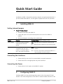
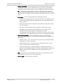
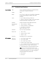
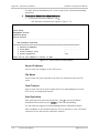
Quick Start Guide
Installation of ASMi-31 should be carried out only by an experienced technician. If
you are familiar with ASMi-31, use this guide to prepare the units for operation.
1.
Installing ASMi-31
Setting Internal Jumpers
To set internal jumpers:
1. Disconnect all cables from ASMi-31.
2. Locate and open a lid on the bottom panel at the rear of the ASMi-31
modem.
3. Set internal jumpers, according to the table below.
Jumper
Function
Possible Settings (Default settings in bold)
JP10, CHASSIS
Controls connection between
signal ground and chassis
ground
CON – Signal ground is connected to chassis ground
Controls the ASMi-31
compatibility with the older
products, for example ASMi-31
with a half duplex management.
NEW – All the features of the unit's current version are
enabled
JP11, COMPAT
DIS – Signal ground is isolated from the chassis ground
OLD – The unit's new features are disabled. ASMi-31 is
fully compatible with older products.
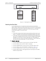
Connecting the Interfaces
1. Connect the line to the RJ-45 or terminal block rear panel connectors.
2. Connect the DTE to the appropriate rear panel connector.
Connecting the Power
•
2.
Connect the AC or DC power to the ASMi-31 modem.
Configuring ASMi-31
Configure ASMi-31 to the desired operation mode via the front panel LCD and
buttons. The initial configuration of the ASMi-31 modem includes selection of the
ASMi-31 Ver. 3.0
Configuring ASMi-31
1
Quick Start Guide
Installation and Operation Manual
clock reference, transmission mode, data format for asynchronous transmission
and operating data rate. Configuration must be performed for the local and
remote modems.
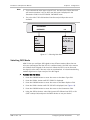
Selecting the Clock Mode
You must select the clock mode for both local and remote modem.
To select clock mode:
•
Scroll to CLKTYPE under LINE CONFIG and select the desired clock type of the
modems (INT RCV, EXT RCV, RCV INT, or RCV EXT).
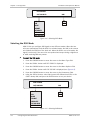
Selecting the Transmission Mode
You must select transmission mode for the modem (synchronous or
asynchronous).
To select transmission mode
•
Scroll to MODE under DTE CONFIG and select the desired transmission mode
(SYNC or ASYNC).
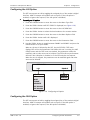
Selecting the Data Format
If you are using asynchronous transmission, you must select the data format
(number of data bits, parity type and number of stop bits).
To select data format:
•
Scroll to FORMAT under DTE CONFIG and select the desired data format.
Selecting the Data Rate
You must select the operation data rate.
To select data rate:
•
2
Scroll to DATARATE under DTE CONFIG and select the desired bit rate.
Configuring ASMi-31
ASMi-31 Ver. 3.0
Contents
Chapter 1. Introduction
1.1
1.2
1.3
1.4
Overview....................................................................................................................1-1
Product Options......................................................................................................1-1
Applications............................................................................................................1-1
Features .................................................................................................................1-2
Physical Description ...................................................................................................1-5
Functional Description................................................................................................1-6
Technical Specifications..............................................................................................1-8
Chapter 2. Installation and Setup
2.1
2.2
2.3
2.4
2.5
2.6
2.7
Introduction...............................................................................................................2-1
Site Requirements and Prerequisites ..........................................................................2-1
Package Contents ......................................................................................................2-2
Equipment Needed.....................................................................................................2-2
Setting Internal Jumpers .............................................................................................2-2
Connecting the Interface Cables .................................................................................2-4
Connecting the Line ................................................................................................2-4
Connecting the DTE ................................................................................................2-5
Making ASMi-31 Compatible with Older Products.....................................................2-5
Connecting the Power ................................................................................................2-6
Chapter 3. Operation
3.1
3.2
3.3
3.4
3.5
Turning ASMi-31 On ...................................................................................................3-1
Controls and Indicators ..............................................................................................3-1
Front Panel .............................................................................................................3-1
Normal Indications..................................................................................................3-2
ASMi-31 Default Settings ...........................................................................................3-3
Configuration Alternatives..........................................................................................3-4
LCD Structure .........................................................................................................3-4
Control Menus ........................................................................................................3-4
Turning ASMi-31 Off ..................................................................................................3-5
Chapter 4. Configuration
4.1
4.2
4.3
4.4
4.5
Menu Tree .................................................................................................................4-1
Configuring Line Parameters.......................................................................................4-2
Selecting the Clock Type .........................................................................................4-2
Selecting the Rate Adaptation Method ....................................................................4-3
Configuring the DTE Parameters .................................................................................4-4
Configuring Transmission Mode...............................................................................4-4
Configuring Data Format .........................................................................................4-5
Selecting the Data Rate ..........................................................................................4-6
Selecting DCD Mode................................................................................................4-7
Selecting the DSR Mode ..........................................................................................4-8
Configuring the LLB Option .....................................................................................4-9
Configuring the RLB Option.....................................................................................4-9
Matching the Line and DTE Settings of the Modems .................................................4-10
Displaying the Modem Status ...................................................................................4-11
ASMi-31 Ver. 3.0
i
Table of Contents
Installation and Operation Manual
Chapter 5. Troubleshooting and Diagnostics
5.1
5.2
5.3
5.4
Detecting Errors.........................................................................................................5-1
Power-Up Self-Test.................................................................................................5-1
Front Panel LEDs.....................................................................................................5-1
Burst Messages.......................................................................................................5-1
Handling Alarms .........................................................................................................5-3
Testing ASMi-31.........................................................................................................5-4
Running Loopback Tests .........................................................................................5-4
Remote Digital Loopback (RLB) ...............................................................................5-5
Running the BER Testing .........................................................................................5-7
Running the LEDs Test ............................................................................................5-8
Technical Support ......................................................................................................5-9
Appendix A. Pinouts
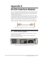
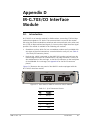
Appendix B. IR-ETH Interface Module
Appendix C. IR-IP Interface Module
Appendix D. IR-G.703/CO Interface Module
ii
ASMi-31 Ver. 3.0
Chapter 1
Introduction
1.1
Overview
ASMi-31 is a 2-wire IDSL modem with remote management, extending data
transmission to 7 km (4.3 miles) over 24 AWG lines. The modem operates in full
duplex over 2-wire links and can be programmed to work at a wide range of data
rates, variable transmission levels, and using different DTE interfaces.
Product Options
The following versions of the modem are available:
•
•
ASMi-31/M – A master standalone version with a front panel LCD and
buttons.
ASMi-31/S – A slave unit features a blank panel with a 20-pin connector. A
portable control unit (PCU) can be connected to the front panel 20-pin
connector to enable changing or monitoring of the slave version.
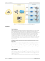
Applications
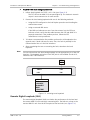
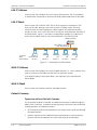
Figure 1-1 illustrates the ASMi-31 central site application with SNMP
management, where four remote ASMi-31 units operates opposite
Megaplex-2100.
ASMi-31 Ver. 3.0
Overview
1-1
Chapter 1 Introduction
Installation and Operation Manual
Figure 1-1. Central Site Application with SNMP Management
Features
Line Interface
ASMi-31 supports full-duplex transmission of 2B+D channels over 2-wire twisted
pair unconditioned line. The line data rate is 160 kbps and the line coding is
2B1Q. This coding provides immunity to the background noise, eliminates normal
line distortion and enables efficient transmission over 2-wire twisted cables.
Using advanced adaptive echo cancellation technique, ASMi-31 supports data
transmission up to 40 dB at 40 kHz and maximum resistance of 130Ω. The
achieved typical range is up to 7 km (4.3 miles) over 24 AWG (0.4 mm) pairs with
nominal line impedance of 135Ω. ASMi-31 line interface terminates in an RJ-45
8-pin connector.
An adaptive equalizer provides noise immunity and high performance over low
quality lines.
ASMi-31 modem is coupled to the telephone lines via an isolation transformer, to
protect it against overvoltages. Additional protection against lightning surges,
power line contact and induction from power lines is provided by using special
components on both sides of the isolation transformer. Line protection complies
with the ITU K.21 requirements.
DTE Interface
ASMi-31 modem supports the following DTE interfaces: RS-530, V.24, V.35, V.36,
X.21, G.703 Codirectional (64 kbps), Ethernet bridge, Ethernet bridge with VLAN
support, and IP router.
ASMi-31 supports both asynchronous and synchronous modes of DTE operation.
1-2
Overview
ASMi-31 Ver. 3.0
Installation and Operation Manual
Chapter 1 Introduction
ASMi-31 operates at eleven selectable synchronous data rates and at eight
selectable asynchronous data rates.
Rate Adaptation
For transmission modes at user rates less than 64 kbps the ASMi-31 modem
supports two methods of rate adaptation at the DTE interface to convert the
user rate into a constant network rate, as specified by the ISDN BRI standard.
•
•
Proprietary RAD method, based on encapsulation of pure data into HDLC
frame (default method).
Standard method, based on the V.110/ECMA.102 guidelines (optional).
Transmit Timing Modes
ASMi-31 supports the following transmit timing modes:
•
•
•
Internal – ASMi-31 uses the internal crystal as clock source.
External – ASMi-31 uses the internal crystal system synchronized by the
external clock coming from the DTE interface.
Receive – Clock is recovered from the received signal.
Clock Modes
The ASMi-31 modem may be configured to operate in the master or in the slave
clock mode.
•
In the slave clock mode the clock rate is recovered from the line, and the
modem must be set to LBT (loopback timing).
•
In the master clock mode the modem provides the clock rate to the system
and is set to either INT (internal clock) or EXT (external clock) mode. If the
EXT clock mode is selected, the unit, after it detected and measured the
“legal” clock (clock supported by the unit), configures itself and the remote
unit at the proper data rate.
Auto External Clock Concept of ASMi-31
When the ASMi-31 modem is in EXT clock mode, it automatically switches itself to
the Auto External Clock mode. In this mode the modem identifies the correct
baud rate and synchronizes the system clock by the external clock. This condition
is called the Steady state.
The modem should pass through the following “states” or phases, two of which
are quite intricate, in order to recognize and configure itself to the external clock
i.e. to reach the Steady state:
1. Initial state: when the user selects the EXT RCV mode, the modem is switched
to Pseudo-Internal mode and sends the proper message to the remote
modem.
2. Detection state: the modem tries to detect and measure the external clock
coming from the DTE.
3. Deduction state: if the clock rate is detected as valid, ASMi-31 continues to
the next phase.
ASMi-31 Ver. 3.0
Overview
1-3
Chapter 1 Introduction
Installation and Operation Manual
If the detected clock is not valid, the modem displays the alarm and sends a
message to the remote unit. The modem continues to look for the valid clock
rate as long as it is in the EXT RCV mode.
4. Activation state: if the clock rate is detected as valid, ASMi-31 displays the
data rate in the DTE Status screen on the LCD and sets the remote unit to
the detected rate.
5. Steady state: the DTE interfaces are enabled after a delay for clock system
stabilization. Data and control signals are received and transmitted to the
external source. At the same time ASMi-31continues to verify the clock rate
(step 2) and if no errors found, remains in the Steady state.
If an illegal clock is received while the modem is in the clock detection process
(steps 2 to 5), it may cause a loss of the current status and the modem and
remote unit begin to exchange error messages.
Control Signal Transfers
ASMi-31 supports end-to-end transfer of two control signals: DTR to DSR and
RTS to DCD, except for the V.35 interface, which does not support the DTR to
DSR signal.
Remote Management
A management channel transmitted inband over the D-channel allows
simultaneous remote configuration for both local and remote modems, real-time
alerts on failures, diagnostic testing, and statistical information on system
performance.
The operator manages both local and remote modems by accessing the front
panel LCD and buttons. Both data and management are transmitted
simultaneously inband without interference.
The configuration parameters are stored in non-volatile memory.
Diagnostics
ASMi-31 contains a built-in internal BERT in async and sync mode for complete
testing of the local and remote modems and data link quality, with no need for
external testing equipment.
V.54 diagnostic loopbacks:
•
•
Local analog loopback
Remote digital loopback
The loopbacks may be activated for both the local and the remote units, by either
LCD front panel switches, or through the DTE interface assigned pins.
Note
Loopback activation from the DTE is not supported by the X.21, G.703
Codirectional or Ethernet interfaces.
Real time alarms provide real time status information on the system’s condition.
Alerts exist to indicate faulty conditions such as:
1-4
Overview
ASMi-31 Ver. 3.0
Installation and Operation Manual
•
•
•
•
Chapter 1 Introduction
Loss of management
Loss of synchronization between modems
NVRAM failure
Configuration mismatch.
Compatibility
The ASMi-31 standalone unit is compatible with the following products:
•
ASM-31
•
ASMi-31 with half-duplex management
•
SRM-31
•
MP-2100 HS-U card
ASMi-31 is compatible with its older versions. When the modem operates
opposite ASMi-31 units with the half-duplex management, the new product
features will be disabled (for example, the full-duplex management will be
unavailable).
For the instructions on making ASMi-31 compatible with the older products, refer
to Making ASMi-31 Compatible with Older Products in Chapter 2.
1.2
Physical Description
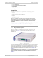
ASMi-31 is available as a standalone unit or as a rack-mount card for the
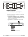
ASM-MN-214 hub. Figure 1-2 shows the 3D view of the ASMi-31 master
standalone unit.
Figure 1-2. ASMi-31/M Unit
The front panel includes eight LEDs, which display the status of power, data flow,
control signals and diagnostics. The LCD together with three buttons is used to
display status (alarm) messages, and diagnostics of ASMi-31/M. You can also use
the LCD and buttons to configure the unit. For details, refer to Chapter 3 and
Chapter 4.
The back panel includes a power connector (AC or DC), a DTE interface connector,
and line connectors. The ASMi-31 rear panel is described in greater detail, in
Chapter 2.
ASMi-31 Ver. 3.0
Physical Description
1-5
Chapter 1 Introduction
Installation and Operation Manual
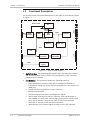
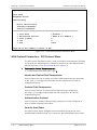
1.3
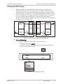
Functional Description
This section contains functional descriptions of the ASMi-31 circuit blocks, shown
in Figure 1-3.
External Clock
PLL
Data
Digital
Interface
CPU
68032
BERT
IOM-2
LEDs
Master
Clock
U-Interface
Data & Add Bus
Memory
PEB - 2070
Data
Line
Overvoltage
Protection
Power
Power
Supply
LCD
LCD
Hybrid Echo
Cancellation
Figure 1-3. ASMi-31 Block Diagram
•
Digital interface – An interchangeable module which translates the received
and transmitted data from TTL levels to any combination of DTE interfaces
supported by the modem.
•
CPU MC68302 – This processor handles the following functions:
Derive command information from and to management channel via
D-channel to change the status and the configuration of the remote unit
(ASMi-31).
Handle the serial bus protocol for the U-interface.
Monitor and command.
Activate and deactivate alarms and diagnostics signals.
Receive data incoming from the DTE interface, either encapsulated or
rate adapted (for rates lower than 64 kbps), and send the data by serial
bus to the U-interface. Compute the same in the reverse direction.
Drive LEDs to indicate status and failure conditions.
Read and carry out command signals arriving from the DTE interface.
1-6
Functional Description
ASMi-31 Ver. 3.0
Installation and Operation Manual
Chapter 1 Introduction
•
Memory (NOVRAM) – New configurations of the local and remote units are
saved by the CPU in the Non Volatile Random Access Memory (NOVRAM).
CPU requires other memory devices, such as EPROM, for proper functioning.
•
PLL – The Phased Locked Loop (PLL) serves to synchronize the fast clock
generated by the internal oscillator with the external clock derived from the
DTE interface. This module is active only while the modem clock is set to EXT
mode.
•
U-interface – The U-interface handles the following functions:
Scramble the data received from serial bus, perform rate adaptation and
transfer the scrambled and rate-adapted data to the appropriate slot in
the superframe.
Extract line data from the superframe, descramble the data and transfer
it to the serial bus.
Recover the clock timing from the superframe, when in LBT mode.
Recognize and perform commands included in the maintenance bit
received from the remote unit in the superframe, such as
activate/deactivate State Machine, transfer the D-channel, perform echo
canceling (EC) of the data transmitted to the line, using hybrid principles.
•
Hybrid line transformer – The EC module in conjunction with the pulse
transformer form the passive line termination circuit. The circuit consists of
three blocks:
Hybrid network – this is a two to four wire converter providing a limited
cancellation of the near end echo.
Compensation circuit – increases the cut-off frequency in the receiver
path, in conjunction with the transformer.
Line pulse transformer – allows passage of a sealing current and of
phantom feed supply through the secondary winding without causing flux
density saturation of the magnetic core, by being designed for low
inductance.
ASMi-31 Ver. 3.0
•
BERT – Generates an internal pseudo random 511-bit test pattern per V.52
ITU standard to test the end-to-end connectivity.
•
Power supply – Provides power to ASMi-31.
Functional Description
1-7
Chapter 1 Introduction
1.4
Line Interface
Installation and Operation Manual
Technical Specifications
Type
2-wire, full duplex operating over unconditioned lines
(twisted pair), using echo cancellation
Coding
2B1Q
Range
Up to 7 km (4.3 miles) over a 24 AWG pair, independent
of data rate according to the ANSI T1.601-1992
guidelines
Levels
• Up to 14 dBm, assuming a 135Ω load
• Between 13 dBm and 14 dBm over the 0 Hz–80 kHz
frequency band (ANSI T1.601-1992 5.3.2.2)
Standard
Complies with ANSI T1.601.1988 specifications
Power Spectral
Density
• 1 kHz to 50 kHz = -30 dB/Hz
• 50 kHz to 500 kHz = -50 dB/decade
• Over 500 kHz = -80 dB/Hz
(ANSI T1.601-1992 5.3.2.1)
Connector
RJ-45 and 3-clip terminal block
Return Loss
• 1 kHz – 0 dB
• 10 kHz to 25 kHz – 20 dB
• 250 kHz – 0 dB
DTE Interface
Protection
According to ITU K.21 requirements
Types and
Connectors
• V.24: 25-pin, D-type, female
• V.35: 34-pin, female
• X.21: 15-pin D-type, female
• RS-530: 25-pin, D-type, female
• V.36: via adapter cable converting between RS-530
connector and 37-pin, D-type, female connector
• G.703 Codirectional: 5-clip terminal block or RJ-45
Note: For the G.703 codirectional interface, byte
synchronization is not kept end-to-end. A violation bit
is inserted every eight bits, but it does not appear in
the same location at the remote end.
• IR-ETH: RJ-45
• IR-IP: RJ-45
1-8
Technical Specifications
ASMi-31 Ver. 3.0
Installation and Operation Manual
Chapter 1 Introduction
Protocol
Synchronous or asynchronous
Data Rates
• Synchronous: 1.2, 2.4, 4.8, 9.6, 16, 19.2, 32, 38.4,
48, 64, 128 kbps
• Asynchronous: 1.2, 2.4, 4.8, 9.6, 19.2, 38.4, 57.6,
115.2 kbps
Note
16, 32, 57.6, 115.2 and 128 kbps are applicable only with RAD proprietary rate
adaptation method. The modem operates also at 56 kbps (V.110 adaptation
only).
Async Format
• Number of data bits – 5/6/7/8 bits,
• Parity – odd, even or no parity,
• Number of stop bits – 1 or 2
Note
Timing
5 bits and 6 bits are not available for the RAD proprietary rate adaptation mode.
Clock Combinations
INT–RCV, RCV–INT, EXT AUTO–RCV, RCV–EXT AUTO
Master Clock
• Internal oscillator is used to receive data from the
DTE and to transmit data to the line.
• External clock from the DTE is used to receive data
from DTE and to transmit data to the line.
If the X.21 interface is used, the same clock is used
to receive and transmit data.
Diagnostics
Slave Clock
• Receive clock derived from the receive signal, looped
back as a transmit clock
V.54 Loopbacks
Local loopback (LLB): activated by management
software or by the DTE interface signal (V.24, V.35 and
RS-530 only)
Remote loopback (REM): activated by management
software or by the DTE interface connector signal (V.24,
V.35, and RS-530 only)
Indicators
ASMi-31 Ver. 3.0
Internal BERT
Built-in pattern generator and tester, complies with
ITU V.52
LEDs Check
Activates the local LEDs for a 3-second period, from the
front panel
PWR (green)
RTS (yellow)
TD (yellow)
RD (yellow)
DCD (yellow)
TST (red)
ALM (red)
SYNC ((green/red)
Power
Request to Send
Transmit Data
Receive Data
Data Carrier Detect
Test
Alarm
Sync Status
Technical Specifications
1-9
Chapter 1 Introduction
Physical
ASMi-31
Height
Power
Environment
4.4 cm (1.7 in)
Width
21.5 cm (8.5 in)
Depth
24.3 cm (9.6 in)
Weight
1-10
Installation and Operation Manual
1.5 kg (3.0 lb)
Wide-range power
supply
100 to 240 VAC, 50 to 60 Hz or -48 VDC nominal
(-40 to -72 VDC)
DC only power
supply
24 VDC
Power Consumption
5W
Temperature
0°–50°C (32°–122°F)
Humidity
Up to 90%, non–condensing
Technical Specifications
ASMi-31 Ver. 3.0
Chapter 2
Installation and Setup
2.1
Introduction
This chapter describes installation and setup procedures for the standalone
ASMi-31 modem.
ASMi-31 is delivered completely assembled. It is designed for tabletop or 19-inch
rack installation. For rack installation instructions, refer to the rack mounting kit
for 19-inch racks guide that comes with the RM kit.
After installing the unit, refer to Chapter 4 for configuration instructions. In case
a problem encountered, refer to Chapter 5 for test and diagnostic instructions.
Internal settings, adjustment, maintenance, and repairs may be performed only
by a skilled technician who is aware of the hazards involved.
Warning
Note
Always observe standard safety precautions during installation, operation, and
maintenance of this product.
Before installing the product, review Handling Energized Products at the
beginning of the manual.
2.2
Site Requirements and Prerequisites
ASMi-31 should be installed within 1.5m (5 ft) of an easily accessible grounded
AC outlet that furnishes 100 VAC to 240 VAC or a -48 or 24 VDC power source,
which must be adequately isolated from the mains supply.
Allow at least 90 cm (36 in) of frontal clearance for operating and maintenance
accessibility. Allow at least 10 cm (4 in) clearance at the rear of the unit for signal
lines and interface cables.
The ambient operating temperature of ASMi-31 is 0° to 50°C (32° to 122°F) at
relative humidity of 90%, non-condensing.
ASMi-31 Ver. 3.0
Site Requirements and Prerequisites
2-1
Chapter 2 Installation and Setup
2.3
Installation and Operation Manual
Package Contents
The ASMi-31 package includes the following items:
•
One ASMi-31 unit
•
Last Mile Access and Intelligent Modems CD
•
CBL-530/449 adapter cable for the ASMi-31 units with V.36 interface
•
AC/DC power plug
•
RM-28 rack mount kit (if ordered).
2.4
Equipment Needed
ASMi-31 is a standalone device intended for tabletop or 19-inch rack installation.
It is delivered completely assembled. No provision is made for bolting the unit on
the tabletop.
The only equipment needed for installing ASMi-31 is a small screwdriver.
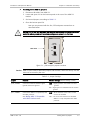
2.5
Setting Internal Jumpers
ASMi-31 contains internal jumpers (JP10 and JP11) that allow you to connect or
isolate the signal ground from the chassis ground and define unit’s compatibility.
Figure 2-1 shows jumper locations. Table 2-1 lists their possible settings.
Access to the inside of the equipment is permitted only to the authorized and
qualified personnel.
Warning
To avoid accidental electric shock, always disconnect the interface cables and the
power cord before removing the unit from its casing.
Line voltages are present inside ASMi-31 when it is connected to power and/or
the lines. Moreover, under certain fault conditions, dangerous voltages may
appear on the lines connected to the unit.
Any adjustment, maintenance and repair of the opened instrument under voltage
must be avoided as much as possible and, when inevitable, should be carried out
only by a skilled technician who is aware of the hazard involved. Capacitors inside
the unit may still be charged even after the unit has been disconnected from its
source of power.
Caution ASMi-31 contains components sensitive to electrostatic discharge (ESD). To
prevent ESD damage, avoid touching the internal components. Before moving the
jumpers, touch the ASMi-31 frame.
2-2
Setting Internal Jumpers
ASMi-31 Ver. 3.0
Installation and Operation Manual
Chapter 2 Installation and Setup
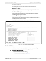
To configure the ASMi-31 jumpers:
1. Disconnect all cables from ASMi-31.
2. Locate and open a lid on the bottom panel at the rear of the ASMi-31
modem.
3. Set internal jumpers, according to Table 2-1.
4. Close the bottom panel lid.
Now you can proceed with the line, DTE and power connections as
described below.
Setting JP10 to DIS may invalidate the safety of connection to telecommunication
networks where permanent hazardous voltages are present on the lines.
Warning
CHASS
CON DIS
Rear Panel
JP10
JP11
NEW OLD
COMPAT
Figure 2-1. JP10 and JP11 Jumper Locations
Caution ASMi-31 also contains additional jumpers and switches, which are factory-set and
must not be moved by the user.
Table 2-1. Jumper Settings
Jumper
Function
Possible Settings (default settings in bold)
JP10, CHASSIS
Controls connection between signal
ground and chassis ground
CON – Signal ground is connected to chassis
ground
DIS – Signal ground is isolated from the chassis
ground
JP11, COMPAT
ASMi-31 Ver. 3.0
Controls the ASMi-31 compatibility with
the older products.
NEW – All the features of the unit's current
version are enabled
See Making ASMi-31 Compatible
with Older Products below
OLD – The unit's new features are disabled.
ASMi-31 is fully compatible with older
products.
Setting Internal Jumpers
2-3
Chapter 2 Installation and Setup
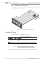
2.6
Installation and Operation Manual
Connecting the Interface Cables
Figure 2-2 illustrates the AC-powered ASMi-31 unit rear panel.
~100-240VAC/
DTE
48/60VDC
LINE
GND 2 4 5
Return
Power
Figure 2-2. ASMi-31 Rear Panel (AC Version)
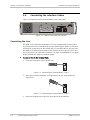
Connecting the Line
The ASMi-31 line interface terminates in a 3-clip terminal block connector and
RJ-45 connectors. The terminal block has two connecting terminals: for transmit
wire and for receive wire on the twisted pair. It is marked LINE for the two wires
and GND for an optional connection of the shield to chassis ground. The 2-wire
line connection is not sensitive to polarity. It is highly recommended to use good
quality twisted pair cable to prevent crosstalk.
To connect line to the terminal block:
1. Insert the screwdriver into a square hole.
Figure 2-3. Connecting the Terminal Block – Step 1
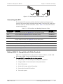
2. Raise the inserted screwdriver, putting pressure on the ramp within the
square hole.
Figure 2-4. Connecting the Terminal Block – Step 2
3. Insert the stripped end of the wire and remove the screwdriver.
2-4
Connecting the Interface Cables
ASMi-31 Ver. 3.0
Installation and Operation Manual
Chapter 2 Installation and Setup
Figure 2-5. Connecting the Terminal Block – Step 3
Connecting the DTE
The rear panel DTE connector provides interface for data input/output, clock
reference and control signal exchange between ASMi-31 and the DTE. RAD offers
interface cables for the DTE connection, refer to Table 2-2 for the DTE interface
connector description.
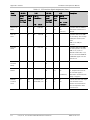
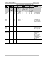
Table 2-2. DTE Interfaces and Matching Connector Cables
DTE Interface
Description
RAD Cable
V.24/RS-232
25-pin, D-type, female (see Appendix A for the connector pinout)
CBL-HBT/V24
V.35
34-pin, female (see Appendix A for the connector pinout)
CBL-HBT/V35
RS-530
25-pin, D-type (see Appendix A for the connector pinout)
CBL-HBT/RS-530
V.36
Via adapter cable converting between RS-530 connector and 37-pin,
D-type, female connector (see Appendix A for the cable pinout)
CBL-530/449
IR-X21
15-pin, D-type (see Appendix A for the connector pinout)
CBL-HBT/X21
IR-G.703/CO
5-clip terminal block or RJ-45 (see Appendix Dfor the module description)
IR-ETH
RJ-45 or BNC (see Appendix B for the module description)
IR-IP
RJ-45 (see Appendix C for the module description)
Making ASMi-31 Compatible with Older Products
ASMi-31 is compatible with the older products: ASM-31, SRM-31, and MP-2100
HS-U cards or ASMi-31 units with half duplex management.
To make ASMi-31 compatible with the older products:
1. Verify that JP11 is in the NEW position and power up ASMi-31.
2. Configure ASMi-31 the modem by its front panel buttons.
3. Turn off the power.
4. Set the JP11 jumper to the OLD position.
5. Connect the line and DTE interface.
6. Turn on the power.
ASMi-31 Ver. 3.0
Connecting the Interface Cables
2-5
Chapter 2 Installation and Setup
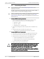
2.7
Note
Installation and Operation Manual
Connecting the Power
Before installing the product, review Handling Energized Products at the
beginning of the manual.
The ASMi-31 power inlet can accept either 100 to 240 VAC or -40 to -72 VDC
(-48 VDC nominal) or 24 VDC without changing any settings.
Note
ASMi-31 is supplied with either a straight or 90° angled power connector that is
used for AC or DC power sources. For connection details, see the DC Power
Supply Connection supplement included in the supplementary information on the
documentation CD.
To connect ASMi-31 to an AC power source:
1. Connect an appropriate approved 3-prong AC power connector to the
open-end cable provided with the unit in the following manner:
Brown wire – Phase
Blue wire – Neutral
Yellow/Green wire – Protective earth.
2. Connect the resulting power cable to the power inlet on the ASMi-31 rear
panel.
3. Connect the other end of the cable to the power source.
The unit turns on automatically upon connection to the mains.
To connect ASMi-31 to a DC power source:
1. Locate and turn off the circuit breaker that supplies the DC branch circuit.
2. Connect the power cable to the power inlet on the ASMi-31 rear panel.
3. Connect the wires to the DC power source in the following order:
Connect the yellow/green wire to the protective earth bus.
Connect the brown wire to the positive (usually earthed) pole.
Connect the blue wire to the negative pole.
4. Switch on the DC power to the branch circuit.
Warning
Before switching on this unit and connecting or disconnecting any other cable,
the protective earth terminals of this unit must be connected to the protective
ground conductor of the mains (AC or DC) power cord. If you are using an
extension cord (power cable) make sure it is grounded as well.
Any interruption of the protective (grounding) conductor (inside or outside the
instrument) or disconnecting of the protective earth terminal can make this unit
dangerous. Intentional interruption is prohibited.
2-6
Connecting the Power
ASMi-31 Ver. 3.0
Chapter 3
Operation
This chapter:
•
Explains how to operate ASMi-31
•
Describes the ASMi-31 modem controls, indicators, and functions
Installation procedures given in Chapter 2 must be completed and checked before
attempting to operate ASMi-31.
3.1
Turning ASMi-31 On
ASMi-31 is turned on as soon as power is connected. When power is connected,
the PWR indicator lights up and remains lit as long as ASMi-31 receives power.
ASMi-31 requires no operator attention once installed, with the exception of
occasional monitoring of front panel indicators. Intervention is only required
when:
•
ASMi-31 must be adapted to new operational requirements
•
Diagnostic tests are performed.
3.2
Controls and Indicators
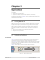
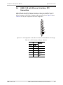
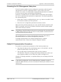
Front Panel
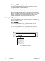
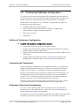
Figure 3-1 shows front panel of the ASMi-31 master modem which includes an
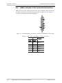
LCD and three buttons serving for the modem configuration. A slave unit
(see Figure 3-2) includes a proprietary 20-pin port for connection of the portable
control unit (PCU). The removable PCU features an LCD and three buttons similar
to those of the master unit.
Table 3-1 lists the ASMi-31 controls, indicators and their functions.
Figure 3-1. ASMi-31/M Front Panel
ASMi-31 Ver. 3.0
Controls and Indicators
3-1
Chapter 3 Operation
Installation and Operation Manual
Figure 3-2. ASMi-31/S Front Panel
Table 3-1. ASMi-31 Front Panel Controls and Indicators
Name
Type
Function
PWR
Green LED
On – Power is on.
RTS
Yellow LED
On – The DTE activates Request To Send.
TD
Yellow LED
On – Steady SPACE is being transmitted.
Blinks – Data is being transmitted.
RD
Yellow LED
On – Steady SPACE is being received.
Blinks – Data is being received.
DCD
Yellow LED
On – A valid receive signal is present.
TST
Red LED
On – ASMi-31 is in any of the two loopback modes, or when a BER tseting
is in progress.
ALM
Red LED
On – A new alarm is detected in the alarm buffer
SYNC
Green/red LED
On (red) – The local modem’s data link is not synchronized with the
remote modem.
On (green) – The modem’s data link is synchronized with the remote
modem.
LCD
Liquid crystal
display
Displays messages and status information.
The display contains 2 rows of 16 characters each.
CURSOR
Button
Moves among the information fields on the LCD
SCROLL
Button
Scrolls among the field options displayed on the LCD
ENTER
Button
Confirms the changes made in the ASMi-31 operation
CONTROL
Connector
Proprietary 20-pin connector for connection of PCU to ASMi-31 slave unit
Normal Indications
Table 3-2 shows the correct status of the indicators, a few seconds after powerup.
3-2
Controls and Indicators
ASMi-31 Ver. 3.0
Installation and Operation Manual
Chapter 3 Operation
Table 3-2. ASMi-31 Indicator Status
3.3
Indicator
Status
PWR
On
LCD Display
Displays opening screen:
“ASMi-31 REV x.x
I N I T I A L I Z I N G...”
SYNC
Red
TST
Off
TD
Depends on DTE data transmission.
RD
Off
RTS
Depends on DTE RTS signal status.
DCD
Off
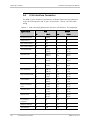
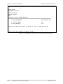
ASMi-31 Default Settings
Table 3-3 and Table 3-4 list default values of the line and DTE parameters.
Table 3-3. Line Parameters
Parameter
Default Value
CLKTYPE
INT RCV
ADAPT
RAD PROP
Table 3-4. DTE Parameters
Note
ASMi-31 Ver. 3.0
Parameter
Default Value
LLB
ENABLE*
RLB
ENABLE*
MODE
SYNC
DATARATE
64K
CNT SIG-DCD
SW
CNT SIG-DSR
SW
For ASMi-31 with X.21, G.703 Codirectional and Ethernet DTE interfaces, the LLB
and RLB default values are always set to DISABLE because these interfaces do not
support loopback activation via DTE connector pins.
ASMi-31 Default Settings
3-3
Chapter 3 Operation
Installation and Operation Manual
3.4
Configuration Alternatives
The ASMi-31 control system enables the user to control and monitor both local
and remote modems using menu-driven software. The menu concept is circular –
the menu screens are displayed on the LCD one after the other in a cyclic order.
A schematic description of the ASMi-31 menu tree is shown in Chapter 4.
This section describes the various menus and how to use them to configure
ASMi-31 and display the status of the modem.
Menu options are selected by the three front-panel buttons and displayed on the
LCD display. Functions of the buttons are described in Table 3-1.
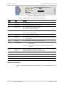
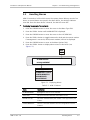
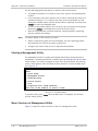
LCD Structure
The ASMi-31 LCD consists of four data fields, as shown in Figure 3-3.
Menu Type
LOC/REM
Menu Options
Parameters
Figure 3-3. LCD Data Fields
•
Menu Type – Scrolls through the available control menus
•
Menu Options – Indicates the control and monitoring options of each control
menu
•
Parameters – Sets the parameter for the controllable menu options
•
LOC/REM – Enables the user to toggle between controlling and monitoring
the local modem or the remote modem.
For the various menu types, the selected parameter (shown in the Parameters
field) is designated by an asterisk (*) shown at the left of the parameter. If you
select a new parameter and confirm the selection (by pressing the ENTER
button), the asterisk will appear at the left of the newly selected parameter.
Control Menus
There are six main menus in the ASMi-31 management software.
3-4
•
LINE STATUS – enables the user to display the current status of the modem
with respect to clock type (CLKTYPE), rate adaptation (ADAPT), test type
performed (TEST) and software version (VERSION).
•
DTE STATUS – enables the user to display DTE data rates, interfaces, modes
and formats for both the local and remote modems.
•
ALARM BUFFER – alerts the user to modem alarms. When the ALM LED is on,
the ALARM BUFFER display indicates the type of the failure. The ALM LED may
blink with no relation to the ALARM BUFFER when an error is detected during
the BER test.
•
CONFIG MATCHING – enables the user to execute a fast matching of the line
and DTE configuration according to the local parameters or according to the
Configuration Alternatives
ASMi-31 Ver. 3.0
Installation and Operation Manual
Chapter 3 Operation
parameters of the remote unit. This menu is active only when a line or DTE
configuration mismatch occurs between the two units. For more details, refer
to Chapter 5.
Note
This command is not active, if the modems are not synchronized to the same
clock.
•
LINE CONFIG – configures of the line parameters.
•
DTE CONFIG – configures both local and remote modem DTE parameters.
•
TESTS – executes several diagnostic tests on the local and remote modems.
If there are alarms stored in the alarm buffer, the device returns to the ALARM
BUFFER screen and display the highest priority alarm in the buffer in the menu
options field.
Note
The LINE CONFIG and DTE CONFIG menus are not available when any of the
diagnostic tests is running.
3.5
Turning ASMi-31 Off
To turn off ASMi-31, remove the power cord from the power source.
ASMi-31 Ver. 3.0
Turning ASMi-31 Off
3-5
Chapter 3 Operation
3-6
Turning ASMi-31 Off
Installation and Operation Manual
ASMi-31 Ver. 3.0
Chapter 4
Configuration
This chapter:
•
Explains how to configure the modem
•
Provides instructions for properly setting up both local and remote modems.
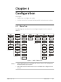
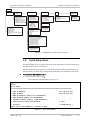
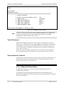
4.1
Menu Tree
The following menu tree shows how to navigate through the various menus of
ASMi-31:
LINE
STATUS
DTE
STATUS
ALARM
BUFFER
CONFIG
MATCHING
LINE
CONFIG
DTE
CONFIG
TESTS
CLKTYPE
DATARATE
CONFIG
MISMATCH
ACCORDING
TO
CLKTYPE
LLB
LLB
ADAPT
INTERFACE
NO
MANAGEMENT
ADAPT
RLB
RLB
TEST
MODE
NVRAM
FAILED
MODE
LLB+BERT
VERSION
FORMAT
NO
INTERFACE
FORMAT
RLB+BERT
CNT
SIG-DCD
ILLEGAL EXT.
CLK
DATARATE
BERT
CNT
SIG-DSR
SYNC LOSS
CNT
SID-DCD
LEDS TEST
EMPTY
CNT
SIG-DSR
Figure 4-1. ASMi-31 Menu Tree
Notes
• CONFIG MATCHING menu is available only if there is line or DTE configuration
mismatch between two modems.
• LINE CONFIG and DTE CONFIG menus are not available when a diagnostic test
is active.
ASMi-31 Ver. 3.0
Menu Tree
4-1
Chapter 4 Configuration
Installation and Operation Manual
4.2
Configuring Line Parameters
Menu options are selected by the three front-panel buttons and displayed on the
LCD display. Functions of the buttons are described in Chapter 3.
The LINE CONFIG menu allows you to configure the line parameters. You can
configure both the local modem and the remote modem, provided that both
modems are connected and the management is active.
When you configure a parameter, when both modems are connected and the
management is active, the message “WAIT...” is displayed while the local modem
sends the new settings to the remote modem and receives an acknowledgment.
Once the acknowledgment is received, the message disappears and the new
setting is displayed with an asterisk next to it. If only the local modem is
connected, or the management is not active, you can configure only the local
modem. In such a case, the message LOC CONFIG ONLY will be displayed on the
LCD for a short period for each parameter you set.
If, at the time you try to configure the system, the party on the other side of the
line is already modifying the configuration, the message “U R BEING CONFIG” will
appear on the LCD and you will not be able to modify the system. You will only be
able to modify the configuration after the other party has finished its
modifications and:
•
A minute has passed since the other party finished and the system returns
back to LINE STATUS.
or
•
The other party scrolled out of LINE CONFIG menu.
The following line parameters are available for configuration:
•
Clock type
•
Rate adaptation mode.
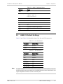
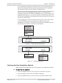
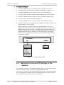
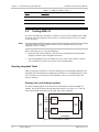
Selecting the Clock Type
You must select the clock mode for both local and remote modem.
To select the clock type:
1. Press the CURSOR button to move to the cursor to the Menu Type field.
2. Press the SCROLL button until LINE CONFIG is displayed (see Figure 4-2).
3. Press the CURSOR button to move the cursor to the Menu Options field.
4. Press the SCROLL button until CLKTYPE is displayed (see Figure 4-3).
5. Press the CURSOR button to move the cursor to the Parameters field.
6. Press the SCROLL button to display the desired clock type (INT RCV, EXT RCV,
RCV INT, or RCV EXT). The left column refers to the settings of the local
modem, and the right column refers to the settings of the remote modem).
7. Press the ENTER button to set your choice.
4-2
Configuring Line Parameters
ASMi-31 Ver. 3.0
Installation and Operation Manual
Chapter 4 Configuration
If you selected the clock type to be EXT RCV, the bit rate of both the local
and remote modems will be set to AUTO and this state will be displayed in
the Parameters field of the DTE CONFIG, DATARATE menu.
At the same time the modem measures the frequency of the external clock. If
the rate is one of those supported by the device, it is displayed in the
Parameters field of the DTE STATUS, DATARATE menu. If the clock rate is not
supported by the device, or no clock is provided, the Parameters field of the
DTE STATUS, DATARATE menu displays AUTO and the ILLEGAL EXT CLK alarm is
stored in the alarm buffer.
If the management is active, the external clock report is sent to the remote
unit and also displays the same parameters as the local unit. If the
management is not active, the remote unit displays the available clock rates
and the operator will have to select the rate manually.
LINE STATUS
DTE STATUS
ALARM BUFFER
LINE CONFIG
DTE CONFIG
TESTS
LINE CONFIG
Menu Options
Parameters
Figure 4-2. Selecting LINE CONFIG Menu
LINE CONFIG
CLKTYPE
CLKTYPE
ADAPT
*INT RCV
INT RCV
EXT RCV
RCV INT
RCV EXT
Figure 4-3. Selecting Clock Type
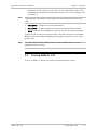
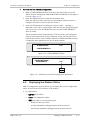
Selecting the Rate Adaptation Method
ASMi-31 supports RAD proprietary and V.110 (option) rate adaptation methods.
To select the rate adaptation:
1. Press the CURSOR button to move the cursor to the Menu Type field.
2. Press the SCROLL button until LINE CONFIG is displayed.
3. Press the CURSOR button to move the cursor to the Menu Options field.
ASMi-31 Ver. 3.0
Configuring Line Parameters
4-3
Chapter 4 Configuration
Installation and Operation Manual
4. Press the SCROLL button until ADAPT is displayed (see Figure 4-4).
5. Press the CURSOR button to move the cursor to the Parameters field.
6. Using the SCROLL button, select RAD PROP or V110 and press the ENTER
button to set your choice.
Note
When configured to the V.110 rate adaptation, ASMi-31 operates in the internal
or receive clock.
LINE CONFIG
ADAPT
CLKTYPE
ADAPT
*RAD PROP
RAD PROP
V110
Figure 4-4. Selecting Rate Adaptation
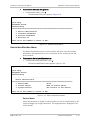
4.3
Configuring the DTE Parameters
The DTE CONFIG menu allows you to select ASMi-31 transmission mode (sync or
async), data format for async mode, data rate, DCD and DSR signal transfer
mode, and enable or disable acceptance of local/remote loopback commands
from the DTE.
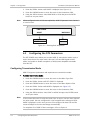
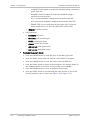
Configuring Transmission Mode
ASMi-31 supports synchronous and asynchronous transmission modes.
To select transmission mode:
1. Press the CURSOR button to move the cursor to the Menu Type field.
2. Press the SCROLL button until DTE CONFIG is displayed.
3. Press the CURSOR button to move the cursor to the Menu Options field.
4. Press the SCROLL button until MODE is displayed (see Figure 4-5).
5. Press the CURSOR button to move the cursor to the Parameters field.
6. Using the SCROLL button, select SYNC or ASYNC and press the ENTER button
to set your choice.
Note
If the current data rate fits only one mode (sync or async), and you have selected
the other mode, the new configuration is not accepted and a message ILLEGAL
MODE is displayed. In such case you must first configure the data rate and the
mode will adapt to the rate and change automatically.
For complete list of ASMi-31 burst messages, refer to Chapter 5.
4-4
Configuring the DTE Parameters
ASMi-31 Ver. 3.0
Installation and Operation Manual
Chapter 4 Configuration
DTE CONFIG
MODE
*ASYNC
LLB
SYNC
ASYNC
RLB
MODE
FORMAT
DATARATE
CNT SIG-DCD
CNT SIG-DSR
Figure 4-5. Selecting Transmission Mode
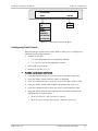
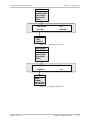
Configuring Data Format
When operating in asynchronous mode, ASMi-31 allows you to configure the
following data format parameters:
•
Number of data bits
7 or 8 for RAD proprietary rate adaptation method
5, 6, 7 or 8 for V.110 rate adaptation method
•
Parity (odd, even or none)
•
Number of stop bits (1 or 2).
To select asynchronous data format:
1. Press the CURSOR button to move the cursor to the Menu Type field.
2. Press the SCROLL button until DTE CONFIG is displayed.
3. Press the CURSOR button to move the cursor to the Menu Options field.
4. Press the SCROLL button until FORMAT is displayed (see Figure 4-6).
5. Press the CURSOR button to move the cursor to the Parameters field.
6. Using the SCROLL button, select appropriate data format and press the
ENTER button to set your choice.
7B NP 1S refers to 7 bits, no parity, 1 stop bit.
8B EP 2S refers to 8 bits, even parity, 2 stop bits, and so on.
ASMi-31 Ver. 3.0
Configuring the DTE Parameters
4-5
Chapter 4 Configuration
Installation and Operation Manual
DTE CONFIG
FORMAT
LLB
RLB
MODE
FORMAT
DATARATE
CNT SIG-DCD
CNT SIG-DSR
*7B NP 1S
7B NP 1S
7B OP 1S
7B EP 1S
7B NP 2S
7B OP 2S
7B EP 2S
8B NP 1S
8B OP 1S
8B EP 1S
8B NP 2S
8B OP 2S
8B EP 2S
Figure 4-6. Selecting Data Format
Selecting the Data Rate
You can select data rates for synchronous and asynchronous transmission
modes. ASMi-31 allows you to select any data rate. If you choose a data rate that
does not conform to the mode to which the modem was set, i.e. a sync data rate
was selected for a modem set to async mode, or vice versa, then the mode
automatically changes to the correct mode.
Examples:
•
•
If the mode is async and you choose a data rate that conforms only to sync
mode, i.e. 128 kbps, then the mode will automatically change to sync mode.
If the mode is sync, the current data rate conforms only to Sync mode, and
you now try to change the mode to async, then the message "ILLEGAL MODE"
will appear. In such a case, to work in async mode, you must change to a
data rate that can be used for sync/async transmission, or select a baud rate
that conforms only to async mode, i.e. 57.6 or 115.2 kbps.
To select a data rate:
1. Press the CURSOR button to move the cursor to the Menu Type field.
2. Press the SCROLL button until DTE CONFIG is displayed.
3. Press the CURSOR button to move the cursor to the Menu Options field.
4. Press the SCROLL button until DATARATE is displayed (see Figure 4-7).
5. Press the CURSOR button to move the cursor to the Parameters field.
6. Using the SCROLL button, select appropriate data rate and press the ENTER
button to set your choice.
4-6
Configuring the DTE Parameters
ASMi-31 Ver. 3.0
Installation and Operation Manual
Note
Chapter 4 Configuration
•
If you selected the clock type to be EXT RCV, the data rate of both the local
and remote modems is set to AUTO and this state is displayed in the
Parameters field of the DTE CONFIG, DATARATE menu.
•
For units with G.703 Codirectional interface only 64 kbps data rate is
available.
DTE CONFIG
DATARATE
*1.2
LLB
SYNC
1.2, 2.4, 4.8, 9.6,
16, 19.2, 32,
38.4, 48, 64, 128
RLB
MODE
FORMAT
DATARATE
ASYNC
1.2, 2.4, 4.8, 9.6,
19.2, 38.4, 57.6,
115.2
CNT SIG-DCD
CNT SIG-DSR
Figure 4-7. Selecting Data Rate
Selecting DCD Mode
ASMi-31 lets you configure DCD signal to two different modes. When the two
units are synchronized and the DCD is in switched mode, the DCD in the remote
unit follows the RTS signal of the local unit. When the DCD is set to ON mode,
the signal is active only if the two units are synchronized. It is deactivated during
modem digital test or upon receipt of the RLB signal.
To select the DCD mode:
1. Press the CURSOR button to move the cursor to the Menu Type field.
2. Press the SCROLL button until DTE CONFIG is displayed.
3. Press the CURSOR button to move the cursor to the Menu Options field.
4. Press the SCROLL button until CNT SIG-DCD is displayed (see Figure 4-8).
5. Press the CURSOR button to move the cursor to the Parameters field.
6. Using the SCROLL button, select SW (remote DCD follows local RTS) or ON
(DCD is always ON) and press the ENTER button to set your choice.
ASMi-31 Ver. 3.0
Configuring the DTE Parameters
4-7
Chapter 4 Configuration
Installation and Operation Manual
DTE CONFIG
CNT SIG-DCD
*SW
LLB
SW
ON
RLB
MODE
FORMAT
DATARATE
CNT SIG-DCD
CNT SIG-DSR
Figure 4-8. Selecting DCD Mode
Selecting the DSR Mode
ASMi-31 lets you configure DSR signal to two different modes. When the two
units are synchronized, and the DSR is in switched mode, the DSR in the remote
unit follows the DTR line of the local unit. When the DSR is set to ON mode, the
signal is active only if the two units are synchronized except during a digital test
or while receiving BER test pattern.
To select the DSR mode:
1. Press the CURSOR button to move the cursor to the Menu Type field.
2. Press the SCROLL button until DTE CONFIG is displayed.
3. Press the CURSOR button to move the cursor to the Menu Options field.
4. Press the SCROLL button until CNT SIG-DSR is displayed (see Figure 4-9).
5. Press the CURSOR button to move the cursor to the Parameters field.
6. Using the SCROLL button, select SW (remote DSR follows local DTR) or ON
(DSR is always ON) and press the ENTER button to set your choice.
DTE CONFIG
CNT SIG-DSR
LLB
RLB
*SW
SW
ON
MODE
FORMAT
DATARATE
CNT SIG-DCD
CNT SIG-DSR
Figure 4-9. Selecting DSR Mode
4-8
Configuring the DTE Parameters
ASMi-31 Ver. 3.0
Installation and Operation Manual
Chapter 4 Configuration
Configuring the LLB Option
The DTE can request an LLB by toggling the assigned pins of the modem’s digital
interface. ASMi-31 accepts and enables such a request (if the LLB option is
enabled) or ignores the request (if the LLB option is disabled).
To configure LLB option:
1. Press the CURSOR button to move the cursor to the Menu Type field.
2. Press the SCROLL button until DTE CONFIG is displayed (see Figure 4-10).
3. Press the CURSOR button to move the cursor to the LOC/REM field.
4. Press the SCROLL button to select the local modem or the remote modem.
5. Press the CURSOR button to move the cursor to the Menu Options field.
6. Press the SCROLL button until LLB is displayed.
7. Press the CURSOR button to move the cursor to the Parameters field.
8. Use the SCROLL button to toggle between ENABLE and DISABLE and press the
ENTER button to set your choice.
When an LLB test is initiated by the DTE, the LINE STATUS, TEST menu
displays DTE>LLB in the Parameters field. While this test is running, the LINE
CONFIG menu and the TEST menu are masked, line parameters cannot be
modified, and no other tests can be initiated. The DTE>LLB test performance
will end if the LLB option is disabled, or if the DTE ends the test request.
When the test is stopped, line parameters can be modified again and other
tests can be initiated.
DTE CONFIG
LLB
LLB
*ENABLE
ENABLE
DISABLE
RLB
MODE
FORMAT
DATARATE
CNT SIG-DCD
CNT SIG-DSR
Figure 4-10. Configuring LLB Option
Configuring the RLB Option
The DTE can request an RLB by toggling the assigned pins of the modem’s digital
interface. ASMi-31 accepts and enables such a request (if the RLB option is
enabled) or ignores the request (if the RLB option is disabled).
ASMi-31 Ver. 3.0
Configuring the DTE Parameters
4-9
Chapter 4 Configuration
Installation and Operation Manual
To configure RLB option:
1. Press the CURSOR button to move the cursor to the Menu Type field.
2. Press the SCROLL button until DTE CONFIG is displayed (see Figure 4-11).
3. Press the CURSOR button to move the cursor to the LOC/REM field.
4. Press the SCROLL button to select the local modem or the remote modem.
5. Press the CURSOR button to move the cursor to the Menu Options field.
6. Press the SCROLL button until RLB is displayed.
7. Press the CURSOR button to move the cursor to the Parameters field.
8. Use the SCROLL button to toggle between ENABLE and DISABLE and press the
ENTER button to set your choice.
When an RLB test is initiated by the DTE, the LINE STATUS, TEST menu
displays DTE>RLB in the Parameters field. While this test is running, the LINE
CONFIG menu and the TEST menu are masked, line parameters cannot be
modified, and no other tests can be initiated. The DTE>RLB test performance
will end if the RLB option is disabled, or if the DTE ends the test request.
When the test is stopped, line parameters can be modified again and other
tests can be initiated.
DTE CONFIG
RLB
LLB
*ENABLE
ENABLE
DISABLE
RLB
MODE
FORMAT
DATARATE
CNT SIG-DCD
CNT SIG-DSR
Figure 4-11. Configuring RLB Option
4.4
Matching the Line and DTE Settings of the
Modems
If a mismatch in the line or DTE configuration parameters of the local and remote
modems is detected, ASMi-31 initiates a CONFIG MISMATCH alarm
(see Figure 4-12) and activates the CONFIG MATCHING menu. This option enables
you to configure both modems with the same parameters, which were stored in
one of them (user’s choice) the last time it was used.
4-10
Matching the Line and DTE Settings of the Modems
ASMi-31 Ver. 3.0
Installation and Operation Manual
Chapter 4 Configuration
To match the two modems configuration:
1. When a CONFIG MISMATCH alarm is stored in the alarm buffer, press the
SCROLL button to display the CONFIG MATCHING ACCORDING TO message on
LCD (see Figure 4-13).
2. Press the CURSOR button to reach the Parameters field.
Using the SCROLL button, select the unit according to which you wish to
configure both sides of the line (local or remote).
3. Press the ENTER button to configure the units (a WAIT ... message is
displayed on the LCD for a short while, while the units are being configured).
The unit returns to the ALARM BUFFER menu and the CONFIG MISMATCH
alarm is erased.
The local modem stores the parameters of the last time it was configured.
Some of these parameters are the parameters of the DTE interface of the
local modem and the remote modem. When the CONFIG MATCHING function
is employed, these parameters are set for both modems.
ALARM BUFFER
LOC
CONFIG MISMATCH
Figure 4-12. CONFIG MISMATCH Alarm
CONFIG MATCHING
ACCORDING TO
LOC
LOC
REM
Figure 4-13. Matching Line and DTE Configuration Parameters
4.5
Displaying the Modem Status
ASMi-31 management software allows you to display the current configuration
status of the line and DTE interfaces of the modem.
•
Line parameters:
CLKTYPE (clock mode)
ADAPT (rate adaptation mode)
TEST (test which is currently performed)
NONE (no tests are active)
LLB (local loopback is being performed by the local unit)
RLB (remote loopback is being performed by the local unit)
ASMi-31 Ver. 3.0
Displaying the Modem Status
4-11
Chapter 4 Configuration
Installation and Operation Manual
LLB+BERT (local loopback in conjunction with BER testing is performed
by the local unit)
RLB+BERT (remote loopback in conjunction with BER testing is
performed by the local unit)
DTE->LLB (local loopback is being performed by the local DTE)
DTE->RLB (remote loopback is being performed by the local DTE)
REMOTE TEST (a test is performed by the remote unit (to find out
which specific test is run, scroll to LINE STATUS→REM→TEST).
VERSION (software version).
•
DTE parameters:
DATARATE (data rate)
INTERFACE (DTE interface type)
MODE (transmission mode)
FORMAT (async data format)
CNT SIG-DCD (DCD signal status)
CNT SIG-DSR (DSR signal status)
To display the modem status:
1. Press the CURSOR button to move the cursor to the Menu Type field.
2. Press the SCROLL button until LINE STATUS or DTE STATUS is displayed.
3. Press the CURSOR button to move the cursor to the LOC/REM field.
4. Press the SCROLL button to select the local modem or the remote modem (if
the management link is not active, remote modem is not available).
5. Press the CURSOR button to move to the Menu Options field.
6. Press the SCROLL button to scroll through the menu options, to one of the
line/DTE parameters and is values (see Figure 4-14 or Figure 4-15).
4-12
Displaying the Modem Status
ASMi-31 Ver. 3.0
Installation and Operation Manual
Chapter 4 Configuration
LINE STATUS
DTE STATUS
ALARM BUFFER
LINE CONFIG
DTE CONFIG
TESTS
LINE STATUS
LOC
CLKTYPE
INTERNAL
CLKTYPE
ADAPT
TEST
VERSION
Figure 4-14. Displaying Line Status
LINE STATUS
DTE STATUS
ALARM BUFFER
LINE CONFIG
DTE CONFIG
TESTS
DTE STATUS
LOC
DATARATE
1.2K
DATARATE
INTERFACE
MODE
FORMAT
CNT SIG-DCD
CNT SIR-DSR
Figure 4-15. Displaying DTE Status
ASMi-31 Ver. 3.0
Displaying the Modem Status
4-13
Chapter 4 Configuration
4-14
Displaying the Modem Status
Installation and Operation Manual
ASMi-31 Ver. 3.0
Chapter 5
Troubleshooting and
Diagnostics
This chapter describes the ASMi-31 diagnostic functions, which include:
•
Power-up self-test, status indications, burst messages, alarms
•
Diagnostic tests (loopbacks and LEDs test)
•
Troubleshooting instructions.
5.1
Detecting Errors
Power-Up Self-Test
ASMi-31 performs a hardware self-test upon turn-on. The self-test sequence
checks the critical circuit functions of the modem.
Front Panel LEDs
The status of ASMi-31 is indicated by the TST and SYNC LED indicators located on
the front panel. For the description of LEDs and their functions, refer to
Chapter 3.
Burst Messages
ASMi-31 responds, in real time, to changes in system status, as dictated by the
user. The following messages will override the current menu display and appear
for a period of about 2 seconds on the ASMi-31 front panel LCD (or on the PCU
LCD).
ASMi-31 Ver. 3.0
•
WAIT – The system is updating the database at this time and no other actions
can be taken.
•
U R BEING CONFIG – Parameters are being configured by the party at the
other side of the line (the remote modem).
•
LOC CONFIG ONLY – The parameter is modified on the local modem only,
since the management channel is not available.
•
TEST ALREADY ON – Activation of test is not valid because another test is
performed (by local or remote modem).
•
NO AUTHORIZATION – This message will appear if the user tries to change
parameters from the standalone or ASMi-31/R modem while it is controlled
via ASMi-31C or ASMi-31CQ installed in LRS-24 modem rack.
Detecting Errors
5-1
Chapter 5 Troubleshooting and Diagnostics
Installation and Operation Manual
•
IR DISABLE DTE – The user tries to initiate a loopback from DTE in a modem
with an interface that doesn’t support the test feature from DTE.
•
NO EXT CLK INPUT – The user tries to change the clock type to a clock type
not supported by the current DTE interface, such as change to external clock
in a modem with Ethernet interface. The clock type will not change.
•
ILLEGAL MODE – The user tries to change to an illegal mode for his current
data rate. For example: to sync mode at the data rate of 57.6 kbps. The
mode will not change.
•
LOC TEST ONLY – The test is activated on the local modem only, since the
management channel is not available.
•
ILLEGAL CLOCK – The user tries to choose the illegal mode for the current
clock. For example, switching to async mode is not allowed when the clock is
EXT-RCV or RCV-EXT. The mode will not change.
•
CLOCK IS CHANGED – There is a momentary loss of synchronization caused by
clock type change and the user tries to change the clock type again before
synchronization is achieved.
•
BERT UNAVAILABLE – The user tries to activate internal BERT, when the
modem is in async mode and number of stop bits = 2 or if the unit is
configured to 5B, NP, 1s with V.110 rate adaptation.
•
NO MATCH REM – Manually selected new parameter conflicts with one or
more parameters, which are already in the database of the remote modem.
For example:
Clock mismatch. The clock of one modem is EXT-RCV/RCV-EXT and the
clock of another is RCV-INT/INT-RCV. Both units are in sync mode. The NO
MATCH REM burst message is displayed if the user tries to change the
mode of the internal clock modem to async (since it cannot be done from
the external clock unit).
Clock mismatch. The clock of one modem is EXT-RCV/RCV-EXT and the
clock of another is RCV-INT/INT-RCV. The burst message appears if the
user tries to change the data rate from the INT-RCV unit (both sync or
async).
Sync/async mode mismatch. Both modems have INT-RCV/RCV-INT clock.
One unit is in sync and another is in async mode. The burst message is
displayed if the user tries to change the clock type to EXT-RCV/RCV-EXT
from the sync modem (since it cannot be done from the async unit).
Rate adaptation mismatch. One modem is in V.110 rate adaptation mode
and another modem is in the proprietary RAD adaptation. The burst
message appears if the user chooses data rate, which is not supported by
the current rate adaptation mode of the unit.
5-2
Detecting Errors
ASMi-31 Ver. 3.0
Installation and Operation Manual
5.2
Chapter 5 Troubleshooting and Diagnostics
Handling Alarms
ASMi-31 contains a buffer which stores the system alarms. When a record of an
alarm, or several alarms are stored in the alarm buffer, the ALM LED indicator
turns ON. Once the alarm buffer is cleared, the ALM LED turns OFF.
To display the alarm buffer contents:
1. Press the CURSOR button to move the cursor to the Menu Type field.
2. Press the SCROLL button until ALARM BUFFER is displayed.
3. Press the CURSOR button to move the cursor to the LOC/REM field.
4. Press the SCROLL button to toggle between the local and the remote modem.
If management is not active, REM (remote modem) will not be displayed.
5. Press the CURSOR button to move to the Menu Options field.
6. Press the SCROLL button to display alarms stored in the buffer (see
Figure 5-1).
REM
LOC
ALARM BUFFER
LOC
NO MANAGEMENT
NO MANAGEMENT
SYNC LOSS
ILLEGAL EXT CLOCK
CONFIG MISMATCH
NVRAM FAILED
NO INTERFACE
Figure 5-1. Displaying Alarms
Table 5-1. ASMi-31 Alarms
ASMi-31 Ver. 3.0
Alarm
Description
NO MANAGEMENT
Management channel is not available.
SYNC LOSS
The synchronization between the modems is lost.
ILLEGAL EXT CLK
The clock rate detected by the modem is not supported by the
modem.
CONFIG MISMATCH
There is a mismatch between the line configurations of both
modems.
Handling Alarms
5-3
Chapter 5 Troubleshooting and Diagnostics
Installation and Operation Manual
Table 5-1. ASMi-31 Alarms (Cont.)
Alarm
Description
NVRAM FAILED
The internal modem NVRAM failed.
NO INTERFACE
The modem does not detect any DTE interface module.
5.3
Testing ASMi-31
The user-controlled test functions of ASMi-31 consist of the loopback tests, BERT
and LEDs test. The purpose of these tests is to determine the source of a break
in the data flow.
Note
The LINE CONFIG and DTE CONFIG menus are not available when any of the
diagnostic tests is running.
Before executing a test, note the following:
•
Both local and remote ASMi-31 units must be configured and synchronized
properly to allow remote loopback activation.
•
Only one loopback can be activated at a time, either on the local or remote
unit. The BER test can be run on both units simultaneously.
Running Loopback Tests
ASMi-31 supports activation of the local analog and remote digital loopbacks. The
loopbacks can be initiated via management software or via designated pins of the
V.24, RS-530 or V.35 interfaces. The loopbacks can be run from the local and
remote modems.
Running the Local Analog Loopback
The local analog loopback (LLB) checks the performance of the local ASMi-31
modem, the local DTE and connection between them (see Figure 5-2). The LLB
can be performed separately on the local and remote modems.
Data
Clock
Transmit
Local
DTE
Line
Interface
Data
Clock
Receive
Local ASMi-31
Figure 5-2. Local Analog Loopback
5-4
Testing ASMi-31
ASMi-31 Ver. 3.0
Installation and Operation Manual
Chapter 5 Troubleshooting and Diagnostics
To perform the local analog loopback test:
1. Initiate local loopback via TESTS > LLB > ON (see Figure 5-3).
The TST LED on the ASMi-31 front panel lights up. The modem's transmit
output is now connected to its own receiver.
2. Execute the local analog loopback with one of the following methods:
Using the DTE configured to the half duplex operation and checking the
echoed data stream.
Using an external BER tester.
If the BER test indicates an error-free data stream, but the DTE test
indicates a fault, verify that the cable between the DTE and ASMi-31 is
properly connected. If the problem persists, follow the DTE
manufacturer's test procedures.
3. To isolate a communication line problem, perform the LLB loopback at the
opposite end. If both LLB tests are error-free, the fault is probably in the
communication line or in the line interfaces.
4. After completing the test or correcting the fault, deactivate the local
loopback.
Note
You can also activate the local analog loopback via the appropriate pin of the DTE
interface. The loopback activation via the DTE pins is not available for the X.21,
Ethernet and G.703 interfaces.
REM
LOC
TESTS
LOC
LLB
*ON
LLB
RLB
LLB+BERT
RLB+BERT
BERT
LEDS TEST
Figure 5-3. Initiating Local Loopback
Remote Digital Loopback (RLB)
The remote digital loopback (RLB) test checks the performance of the local and
the remote ASMi-31 units and their connecting lines. The RLB sets a loop at the
remote ASMi-31 unit from the DTE coupled to the local unit (see Figure 5-4).
ASMi-31 Ver. 3.0
Testing ASMi-31
5-5
Chapter 5 Troubleshooting and Diagnostics
Installation and Operation Manual
Data
Clock
Transmit
Receive
Local
DTE
Line
Interface
Line
Interface
Remote
DTE
Data
Clock
Receive
Transmit
Local ASMi-31
Remote ASMi-31
Figure 5-4. Remote Digital Loopback
To activate the remote digital loopback:
1. Initiate remote loopback via TESTS > RLB > ON (see Figure 5-5).
The TST LED on each ASMi-31 front panel lights up. The receive output of
the remote modem is looped back to the transmitter.
Note
You can also activate the remote digital loopback via the appropriate pin of the
DTE interface. The loopback activation via the DTE pins is not available for the
X.21, G.703 and Ethernet interfaces.
2. Perform the RLB test as explained above for the local analog loopback test.
If an error occurs, but the local analog loopback test was successful for both
the local and remote modems, it can be assumed that the line of the local or
the remote unit is not operating properly.
3. After completing the test or correcting the fault, deactivate the remote
loopback.
REM
LOC
TESTS
LOC
RLB
*ON
LLB
RLB
LLB+BERT
RLB+BERT
BERT
LEDS TEST
Figure 5-5. Initiating Remote Loopback
5-6
Testing ASMi-31
ASMi-31 Ver. 3.0
Installation and Operation Manual
Chapter 5 Troubleshooting and Diagnostics
Running the BER Testing
ASMi-31 includes an internal BER tester, which tests the line quality and
calculates the bit error rate in the data stream. The ASMi-31 BERT transmits a
pseudo-random 511-bit pattern according to V.52 standard. A pattern evaluator
receives the pattern, compares it to the transmitted pattern and detects errors. If
errors are detected by the pattern evaluator, the ALM LED blinks or remains ON.
You can run BER testing simultaneously on the local and remote ASMi-31
modems, thus checking the integrity of the link from both sides of the application
at the same time (see Figure 5-6).
Pattern
Tester
Pattern
Generator
Line
Interface
Line
Interface
Pattern
Tester
Pattern
Generator
Local ASMi-31
Remote ASMi-31
Figure 5-6. Running Two BER Tests Simultaneously
To run a BER testing:
•
Initiate BER testing via TESTS > BERT > ON (see Figure 5-7).
The display changes to 0.00E-7.
If an error is detected, the ALM LED blinks and the display shows the
bit error rate of the data stream.
REM
LOC
TESTS
LOC
BERT
*ON
LLB
RLB
LLB+BERT
RLB+BERT
BERT
LEDS TEST
Figure 5-7. Initiating BER Testing
ASMi-31 Ver. 3.0
Testing ASMi-31
5-7
Chapter 5 Troubleshooting and Diagnostics
Installation and Operation Manual
Combining BER Testing with Loopbacks
You can also combine the LLB and RLB with the BER testing by activating a
corresponding loopback and BERT simultaneously.
The ASMi-31 management software allows you to combine the channel or remote
digital loopbacks with BERT by selecting LLB+BERT or RLB+BERT from the TEST
menu.
When combining the BER testing with one of the loopbacks, an internal pattern
generator connects the standard 511-bit pattern to the transmit input of the DTE
interface. The receive output is connected to the pattern evaluator, which
compares the received and transmitted patterns, and detects errors.
Running the LEDs Test
The LEDs test enables you to check that the LED indicators on the modem's front
panel are functioning properly.
To run the LEDs test:
1. Press the CURSOR button to move the cursor to the Menu Type field.
2. Press the SCROLL button until TESTS is displayed.
3. Press the CURSOR button to move the cursor to the Menu Options field.
4. Press the SCROLL button until LEDS TEST is displayed (see Figure 5-8).
5. Press the ENTER button to start the LEDs test.
All the LEDs light briefly and then return to their normal status.
TESTS
LEDS TEST
LLB
RLB
LLB+BERT
RLB+BERT
BERT
LEDS TEST
Figure 5-8. Running LEDs Test
5-8
Testing ASMi-31
ASMi-31 Ver. 3.0
Installation and Operation Manual
5.4
Chapter 5 Troubleshooting and Diagnostics
Technical Support
Technical support for this product can be obtained from the local distributor from
whom it was purchased.
For further information, please contact the RAD distributor nearest you or one of
RAD's offices worldwide. This information can be found at www.rad.com (offices
– About RAD > Worldwide Offices; distributors – Where to Buy > End Users).
ASMi-31 Ver. 3.0
Technical Support
5-9
Chapter 5 Troubleshooting and Diagnostics
5-10
Technical Support
Installation and Operation Manual
ASMi-31 Ver. 3.0
Appendix A
Pinouts
A.1
V.24, V.35, X.21 and RS-530 DTE Interface
Connectors
Table A-1 lists the pin assignments of the V.24/RS-232, V.35, X.21 and RS-530
interface connectors.
Table A-1. DTE Interface Signal Assignments
Signal
Function
V.24
V.35
DB-25
Standalone and
Card Cage
DB-25
Card
Cage
Protective
Ground
1
1
Signal
Ground
7
Transmitted
Data
Received
Data
RS-530
Description
DB-25
Standalone
and Card
Cage
DB-25
Card
Cage
A Frame 101
1
1
1
(Shield)
Chassis Ground. It may
be isolated from Signal
Ground.
7
B
Signal 102
7
7
8
(GND)
Common signal and DC
power supply ground.
2
9
11
P
S
TD(A) 103
TD(B) 103
2
14
2
14
2
9
(Transmit)
Serial digital data from
DTE. In sync
applications, the data
translations must
occur on the rising
edge of the transmit
clock.
3
12
13
R
T
RD(A) 104
RD(B) 104
3
16
3
16
4
11
(Receive)
Serial output from the
modem receiver. In
sync applications, the
data translations occur
on the rising edge of
the clock.
ASMi-31 Ver. 3.0
34-Pin
Standalone
X.21
Pin
Circuit
DB-15
Standalone
Pin
Circuit
(Function)
V.24, V.35, X.21 and RS-530 DTE Interface Connectors
A-1
Appendix A Pinouts
Installation and Operation Manual
Table A-1. DTE Interface Signal Assignments (Cont.)
Signal
Function
RS-232
DB-25
Standalone and
Card Cage
V.35
DB-25
Card
Cage
RS-530
34-Pin
Standalone
Pin
Circuit
X.21
DB-25
Standalone and
Card Cage
DB-25
Card
Cage
4
19
Description
DB-15
Standalone
Pin Circuit
(Function)
4
4
C
RTS 105
4
19
Clear to
Send
5
5
D
CTS 106
5
13
A positive level from ASMi31 with delay, after receipt
of Request to Send, and
when
ASMi-31 is ready to
transmit.
Data Set
Ready
6
6
E
DSR 107
6
22
A positive level from ASMi31 when power is on, and
ASMi-31 is (a) not in
DIGITAL LOOP mode, or (b)
has not received a REMOTE
LOOPBACK signal from the
remote unit.
Data
Terminal
Ready
20
20
H
DTR 108
20
23
Not used
Carrier
Detect
8
8
F
DCD 109
8
10
8
10
3
10
(Control)
A positive level to ASMi-31
when data transmission is
desired.
Request to
Send
5
12
(Indication)
External
Transmit
Clock
A-2
24
19
16
U SCTE(A) 113
W SCTE(B) 113
24
11
V.24, V.35, X.21 and RS-530 DTE Interface Connectors
24
11
7
14
A positive level from ASMi31, except when a loss of
the received signal is
detected or when Data Set
Ready is negative.
A serial data rate clock input
from the data source.
Positive clock translations
must correspond to data
transmissions.
ASMi-31 Ver. 3.0
Installation and Operation Manual
Appendix A Pinouts
Table A-1. DTE Interface Signal Assignments (Cont.)
Signal
Function
RS-232
V.35
DB-25
Standalone and
Card Cage
DB-25
Card
Cage
Transmit
Clock
15
14
10
Receive
Clock
17
Local
Analog
Loop
RS-530
Description
DB-25
Standalone
and Card
Cage
DB-25
Card
Cage
DB-15
Standalone
Y SCT(A) 114
a SCT(B) 114
15
12
15
12
6
S(A)
13 S(B)
(Signal
timing)
23
22
V SCR(A) 115
X SCR(B) 115
17
9
A receive data rate
clock output used by
an external data sink.
Positive clock
translations
correspond to data
translations.
18
18
L and j
18
A control signal input,
which, when on, sets
ASMi-31 into Local
Analog Loopback
(V.54 Loop 3).
Remote
Digital Loop
21
21
N and h
21
A control signal input
which, when on,
commands
ASMi-31 to send a
remote Loopback
command (V.54 Loop
2) to the remote
ASMi-31.
Test
Indicator
25
25
n and k
25
A Control Signal
output from
ASMi-31; positive
during any test mode.
ASMi-31 Ver. 3.0
34-Pin
Standalone
X.21
Pin
Circuit
Pin Circuit
(Function)
A transmit data rate
clock for use by an
external data source.
Positive clock
translations
correspond to data
translations.
V.24, V.35, X.21 and RS-530 DTE Interface Connectors
A-3
Appendix A Pinouts
Installation and Operation Manual
A.2
V.36 Interface Connector
The ASMi-31 V.36 interface is provided via an adapter cable converting between
25-pin RS-530 connector and 37-pin V.36 connector. Table A-2 lists the cable
wiring.
Table A-2. Cable Converting between RS-530 and V.36 Interfaces, Pin Assignment
Signal Function
A-4
V.36
RS-530
Pin
Circuit
Pin
Protective Ground
1
Shield
1
Signal Ground
19
SG
7
AB
DTE Common Return
37
SC
DCE Common Return
20
RC
Transmitted Data
4
22
SD (A)
SD (B)
2
14
BA (A)
BA (B)
Received Data
6
24
RD (A)
RD (B)
3
16
BB (A)
BB (B)
Request to Send
7
25
RS (A)
RS (B)
4
19
CA (A)
CA (B)
Clear to Send
9
27
CS (A)
CS (B)
5
13
CB (A)
CB (B)
Data Set Ready
11
29
DM (A)
DM (B)
6
22
CC (A)
CC (B)
Data Terminal Ready
12
30
TR (A)
TR (B)
20
23
CD (A)
CD (B)
Carrier Detect
13
31
RR (A)
RR (B)
8
10
CF (A)
CF (B)
External Transmit
Clock
17
35
TT (A)
TT (B)
24
11
DA (A)
DA (B)
Transmit Clock
5
23
ST (A)
ST (B)
15
12
DB (A)
DB (B)
Receive Clock
8
26
RT (A)
RT (B)
17
9
DD (A)
DD (B)
Local Analog
Loopback
10
LL
18
LL
Remote Loopback
14
RL
21
RL
Test Indicator
18
TM
25
TM
V.36 Interface Connector
Circuit
ASMi-31 Ver. 3.0
Installation and Operation Manual
A.3
Appendix A Pinouts
ASMi-31/R with Ethernet Interface, DTE
Connection
ASMi-31/R with the IR-ETH Ethernet interface module uses a CIA/ETH interface
adapter, which converts one DB-25 connector to an RJ-45 connector. If you
intend to prepare a DB-25/RJ-45 adapter cable yourself, refer to Figure A-1 and
Table A-3 for the pin designations and their assignment.
7
9
11
12
13
Figure A-1. Pin Designation in the DB-25 Connector of ASM-MN-214 Card Cage
Table A-3. DB-25 and RJ-45 Pinout, Ethernet
Pin
ASMi-31 Ver. 3.0
Function
RJ-45
DB-25
3
13
RCV (+)
6
12
RCV (-)
1
11
XMT (+)
2
9
XMT (-)
–
7
GND
ASMi-31/R with Ethernet Interface, DTE Connection
A-5
Appendix A Pinouts
Installation and Operation Manual
A.4
ASMi-31/R with G.703 Codirectional Interface
ASMi-31/R with G.703 Codirectional interface uses an adapter cable that converts
one DB-25 connector to an RJ-45 connector. Refer to Figure A-2 and Table A-4
for the pin designations and their assignment.
2
7
9
16
11
Figure A-2. Pin Designation in the DB-25 Connector of ASM-MN-214 Card Cage
Table A-4. DB-25 and RJ-45 Pinout, G.703 Codirectional
Pin
A-6
Function
RJ-45
DB-25
3
9
RCV (+)
6
11
RCV (-)
4
2
XMT (+)
5
16
XMT (-)
2
7
GND
ASMi-31/R with G.703 Codirectional Interface
ASMi-31 Ver. 3.0
Appendix B
IR-ETH Interface Module
IR-ETH is an interface module for RAD modems, used for converting the Ethernet
(10BaseT or 10Base2) electrical levels to the modem TTL levels. It also converts
the Ethernet protocol to HDLC to enable long-distance transmission and avoid
the Ethernet collision limitation.
IR-ETH includes an internal, self-learning Ethernet bridge, which enables a high
performance link between two Ethernet segments at a low transmission rate. The
low-speed HDLC transmission is sent over the link using the modem modulation
technique. It is converted back to an Ethernet signal at the remote modem.
Figure B-1 shows a typical application using an Ethernet interface bridge. Each
modem is connected to an Ethernet network via the Ethernet interface bridge.
ASMi-31
ASMi-31
Figure B-1. Typical Application of ASMi-31 with IR-ETH Module
B.1
IR-ETH Connector Options
Figure B-2 shows the rear panel of ASMi-31 with the IR-ETH option. Table B-1
lists the RJ-45 connector pinout.
Appendix A describes the pinout of the DB-25 connector serving the LAN
connection of the ASMi-31/R card.
~100-240VAC/
48/60VDC
LINE
10BASE-T
Return
Power
LINK
RX
COLL
TX
GND 2 4 5
Figure B-2. ASMi-31 Rear Panel with IR-ETH/UTP Connector
IR-ETH Connector Options
B-1
Appendix B IR-ETH Interface Module
ASMi-31 Installation and Operation Manual
Table B-1. RJ-45 Connector Pinout
B.2
General
LAN
WAN
B-2
Pin
Signal
3
RCV (+)
6
RCV (-)
1
XMT (+)
2
XMT (-)
–
GND
Technical Specifications
LAN Table
10,000 addresses
Filtering and Forwarding
15,000 pps
Buffer
256 frames
Delay
1 frame
Standard
Conforms to IEEE 802.3/Ethernet
Data Rate
10 Mbps (20 Mbps 10BaseT FDX)
Connectors
• 10BaseT (UTP): Shielded RJ-45
Protocol
HDLC
Data Rate
According to the modem transmission rate
Technical Specifications
ASMi-31 Installation and Operation Manual
B.3
Appendix B IR-ETH Interface Module
Installation and Operation
Figure B-3 shows the IR-ETH layout, the locations of the DIP switch, and the rear
panel components for the UTP version.
4
3
2
1
Figure B-3. IR-ETH Module Layout (UTP Option)
Setting the DIP Switch
Set the IR-ETH DIP switch according to Table B-2.
Table B-2. DIP Switch Settings
Switch Number
Name
Description (Default setting in bold)
1
SQ/FD
On – Ethernet full-duplex mode
Off – Ethernet half-duplex mode
Note: The SQ/FD switch is not used in the Ethernet bridge with the BNC connector option.
2
CMP
On – Strips padding bits inserted in 64-byte frame
Off – Transmits frames over WAN as is
3
FIL
On – Passes only frames destined for another LAN
Off – Disables LAN filter, passes all frames transparently
Installation and Operation
B-3
Appendix B IR-ETH Interface Module
ASMi-31 Installation and Operation Manual
LED Indicators
Table B-3 lists the IR-ETH LED indicators and describes their functions.
Table B-3. IR-ETH Bridge LED Indicators
LED Name
Description
Location
Color
LINK
ON – Good link integrity (available only in the 10BaseT version)
Panel
Green
RX
ON – Data is received from the Ethernet attached segment
Panel
Yellow
TX
ON – Data is transmitted from the modem to the Ethernet segment
Panel
Yellow
ERR D4
ON – Bridge buffer overrun occurred
On-board
Red
Connecting the LAN
For 10BaseT installation, either a straight cable or a cross cable may be required.
Use a cross cable when connecting to a port that does not implement the
crossover function internally. Otherwise, use a straight cable.
Note
B-4
Hubs usually do implement the crossover function internally while network
interface cards and other devices do not.
Installation and Operation
Appendix C
IR-IP Interface Module
C.1
Introduction
Overview
IR-IP is a high-performance, miniature IP router based on RAD's unique IP router
chip, the ChipRouter.
IR-IP works by taking each Ethernet frame from the LAN and determining whether
the IP packet is destined for the IP net on the Ethernet LAN. If not, IR-IP forwards
the packet to the WAN (line) link. IP packets received from the WAN link are
automatically forwarded to the LAN if the IP net matches.
IR-IP includes hardware filters which handle all filtering operations at wire speed
from both LAN-to-WAN and WAN-to-LAN, without dropping a single packet.
Filtering and forwarding are performed at the maximum rate of 35,000 and
30,000 frames per second (wire speed), respectively. The buffer can hold
256 frames of maximum size of 1534 bytes and a throughput latency of one
frame.
IR-IP is available with 10BaseT (UTP) interface and is fully
IEEE 802.3/Ethernet v2 compliant. The IR-IP interface can also operate in full
duplex Ethernet applications.
ASMi-31 equipped with IR-IP interface module can be used as a Frame Relay
Access Device (FRAD) with an integral IP router. RFC 1490 is supported for a
single DLCI on the WAN link. Detection of the DLCI and the maintenance protocol
is performed automatically. This allows the IR-IP to be used as the termination
unit of IP services over Frame Relay at the customer premises, opposite a Frame
Relay switch in the backbone.
Alternatively, Point-to-Point Protocol (PPP) can be run on the WAN link with
automatic negotiation on power-up, as well as support for PAP and CHAP
authentication. With this feature, IR-IP can operate opposite any PPP compliant
access server or backbone router.
IR-IP supports HDLC, which is especially important for broadcast and multicast
applications where bandwidth overhead is critical.
IR-IP supports IP multicast at wire speed, making it suitable for any multicast
environment including high speed downstream environments, such as satellite
and xDSL. Users on the LAN who register with IR-IP for an IP multicast group
using the IGMP protocol filter IP multicast packets at wire speed.
Management and advanced configuration are performed via Telnet.
ASMi-31 Ver. 3.0
Introduction
C-1
Appendix C IR-IP Interface Module
Installation and Operation Manual
Application
Figure C-1 shows a typical application of the ASMi-31 modem equipped with the
IR-IP interface module.
ASMi-31
with IR-IP
ASMi-31
with V.35 Interface
Router
Figure C-1. Typical Application of ASMi-31 with IR-IP
C.2
Technical Specifications
Router
LAN
WAN
LAN IP Net
Up to 256 hosts on LAN IP net
Filtering and
Forwarding
30 kbps/35 kbps
Buffer
256 frames (maximum size – 1534 bytes)
Delay
1 frame
Standard
Conforms to IEEE 802.3/Ethernet v2
Data Rate
10 Mbps
(20 Mbps 10BaseT in full duplex topology)
Connector
10BaseT (UTP): Shielded RJ-45
Protocols
• PPP (PAP/CHAP)
• Frame Relay (RFC 1490)
• HDLC
C.3
Physical Description
Figure C-2 shows the rear panel of ASMi-31 with the IR-IP interface module.
~100-240VAC/
48/60VDC
LINE
10BASE-T
GND 2 4 5
ACT
ERR
INT
Return
Power
IR-IP
Figure C-2. Rear Panel of ASMi-31 with the IR-IP Module
C-2
Physical Description
ASMi-31 Ver. 3.0
Installation and Operation Manual
Appendix C IR-IP Interface Module
IR-IP LEDs
IR-IP contains three LEDs, which indicate the module activity. Table C-1 lists the
LEDs functions.
Table C-1. IR-IP LEDs Functions
Name
Type
Function
INT
Green LED
ON – LAN integrity is established.
ACT
Yellow LED
Blinks – Transmit/receive activity is detected on the
Ethernet link.
ERR
Red LED
ON – Buffer overflow occurred (during normal operation).
During power-up, provides additional indications,
described below.
IR-IP DIP Switch
IR-IP interface module contains a four-section DIP switch, as seen in Figure C-3.
Table C-2 lists the DIP switch functions.
Figure C-3. IR-IP DIP Switch
Table C-2. IR-IP DIP Switch Functions
No
Function
Settings (Default settings in bold)
1
Enables IR-IP to learn its IP
On – IP address learning is enabled
Off – IP address learning is disabled
2
Selects the WAN protocol
On – PPP protocol
Off – Frame Relay protocol
3
Selects the LAN mode
On – Full duplex operation
Off – Half duplex operation
4
Controls the remote WAN test
loopback, which returns packets
received from the WAN back
toward the WAN
On – The test loopback is activated
Off – The test loopback is disabled
Table C-3 provides the pinout of the IR-IP RJ-45 connector.
ASMi-31 Ver. 3.0
Physical Description
C-3
Appendix C IR-IP Interface Module
Installation and Operation Manual
Table C-3. RJ-45 Pinout
C.4
Pin
Name
Function
1
TD (+)
Transmit data (positive)
2
TD (-)
Transmit data (negative)
3
RD (+)
Receive data (positive)
6
RD (-)
Receive data (negative)
Preliminary Configuration of ASMi-31 with IR-IP
Before starting configuration of the IR-IP interface module, make sure to set the
following jumpers of the local and remote units as detailed below:
•
RLB jumper (JP14) – DIS
•
LLB jumper (JP15) – DIS
•
Section 6 (DCD) of the SW6 DIP switch – ON
•
Section 7 (DSR) of the SW6 DIP switch – ON.
C.5
IR-IP Management Subsystem, General
Introduction
The IR-IP interface module management subsystem supports the following
functions:
•
•
•
•
•
Preliminary configuration
Configuration of management access parameters
Advanced configuration of IR-IP parameters
Collection and display of statistical performance data
Maintenance functions, which include:
Software downloading
Resetting of various subsystems
Display of error log
Ping utility, for checking IP connectivity.
The management subsystem of the IR-IP interface module is a separate,
independent entity.
The communication with the IR-IP management subsystem is made through the
local LAN interface connector of the IR-IP module, designated 10BASE-T, using
the Telnet protocol. Passwords can be used to prevent unauthorized access.
C-4
IR-IP Management Subsystem, General
ASMi-31 Ver. 3.0
Installation and Operation Manual
Appendix C IR-IP Interface Module
Accessing the IR-IP Management Subsystem
The IR-IP interface module must be configured in accordance with the specific
requirements of the user’s application before it can be used in the user’s
network. As a result, it is not possible to supply default parameters to enable IRIP to start service without any preliminary configuration.
Therefore, to enable the user to establish Telnet communication and configure
IR-IP, IR-IP is delivered with a default set of parameters. The default parameters
are automatically used:
•
Before the IP router is configured by the user, e.g., when a new ASMi-31 with
IR-IP interface module is put into operation
•
After the user’s configuration parameters have been erased.
When the factory-default parameters are used, the ERR indicator located on the
ASMi-31 rear panel, near the IR-IP Ethernet interface connector flashes rapidly
(about three times per second).
Note
The flashing of the ERR indicator also serves as a warning to the user that the IRIP WAN interface does not send, nor does it receive packets, and therefore IR-IP
can be accessed only from the LAN.
After configuring IR-IP, it starts normal operation and routes the traffic in
accordance with the user-selected configuration parameters.
To change the parameters of an already-configured IR-IP, establish
communication from a Telnet host using the assigned IP address.
Default IP Communication Parameters
The default IP communication parameters of the interface module are:
•
The default IP address of the IR-IP Ethernet port is 192.168.205.1, and the
default IP subnet mask is 255.255.255.252.
•
The port will accept IP communication only from the IP address
192.168.205.2. Therefore, as long as the factory defaults are in effect, you
must assign this address to the Telnet host used to configure IR-IP.
Using the IP learning mechanism, as explained below you can change the default
parameters.
Note
ASMi-31 Ver. 3.0
In the default configuration, the IR-IP WAN interface is disabled. In order to
enable the WAN interface, you have to modify the Ethernet port address or the IP
subnet mask.
IR-IP Management Subsystem, General
C-5
Appendix C IR-IP Interface Module
C.6
Installation and Operation Manual
Performing Preliminary Configuration
The software necessary for performing all the management and configuration
functions is stored in the IR-IP interface module, and therefore you only need a
regular Telnet host to perform all the activities described in this appendix.
A Telnet host is any computer, e.g., an IBM PC or compatible that fulfills the
following minimum requirements:
•
A standard 10BaseT Ethernet interface
•
A TCP/IP protocol stack, and therefore is capable of supporting IP
communication through the Ethernet interface
•
Telnet client software
•
A ping utility.
Outline of Preliminary Configuration
To perform the preliminary configuration procedure:
1. Connect the Telnet host to the IR-IP interface module.
2. Configure the Telnet host to enable communication with the IR-IP interface
module using the default IP parameters.
3. Establish communication with IR-IP and assign the prescribed IP address to its
LAN interface.
4. Establish again communication with IR-IP and continue the preliminary
configuration in accordance with the Quick Setup Menu section below.
Connecting the Telnet Host
Before starting the management and configuration activities, it is necessary to
establish IP communication between your Telnet host and the IR-IP interface
module. For this purpose, it is necessary to provide a communication path.
Because of the method used to assign an IP address to IR-IP Ethernet port, it is
recommended to connect the Telnet host directly to the IP router 10BASE-T
connector. This is made by connecting an Ethernet cross cable between the
Ethernet connector of the Telnet host and the IR-IP connector.
However, you may also connect through a common LAN: in this case, connect
your Telnet host and IR-IP to Ethernet hub ports using straight cables.
Preliminary Telnet Host Configuration
You can use the IP learning mechanism to configure the IP communication
parameters of the IR-IP LAN interface. In this case, skip to the Assigning the
Router LAN Interface Address section below.
If you prefer to use the factory-default parameters to establish IP communication
between your Telnet host and IR-IP, configure the Telnet host as follows:
C-6
Performing Preliminary Configuration
ASMi-31 Ver. 3.0
Installation and Operation Manual
Appendix C IR-IP Interface Module
1. Temporarily configure the host IP address as 192.168.205.2.
2. The initial destination IP address to be used by the host is 192.168.205.1.
Note
The first step in the preliminary configuration process is to assign the desired IP
address to the LAN interface of the IR-IP interface module.
After an IP address is assigned and saved, you must change the destination IP
address of the Telnet host to the new address, otherwise it is not possible to
continue the configuration process. At the same time, you can also change the
temporary IP address assigned to the host (192.168.205.2) back to its
permanent address.
Assigning the Router LAN Interface Address
The IP address of the IR-IP LAN interface must be configured as part of the
preliminary configuration process. To simplify this process, IR-IP includes a simple
and convenient IP address learning mechanism.
The IP address can be configured and changed at any time, even after the
complete IR-IP configuration process has been performed, because it does not
affect other configuration parameters. Moreover, the IP subnet mask is
automatically adapted to the new IP address.
IP Learning Mechanism
To simplify the configuration process, IR-IP has a special mechanism for
configuring the IP address of its LAN interface. Setting section 1, called IP address
learning, of the IR-IP DIP switch (Figure C-3) to ON enables this mechanism.
The IP learning mechanism enables IR-IP to learn its LAN interface IP address by
receiving frames sent by a ping utility to the prescribed LAN IP address.
Note
To use the IP learning mechanism, you do not need to know the current address
of IR-IP LAN interface, but only the prescribed IP address.
The IP address is actually retrieved from the ARP frames sent during pinging to
locate the ping destination, not from the ping frames.
To ensure that the process is correctly performed, it is recommended to check
the contents of the ARP table before starting the ping utility, to make sure that it
does not contain the address to be assigned to the IP router LAN interface.
To view and edit the ARP table contents:
If the Telnet host you are using runs under Microsoft Inc. Windows™ 95, 98 or
NT, use the following procedure to view and edit the ARP table contents:
1. Display the table using the arp -a command.
2. If the table includes the intended IP address, remove it from the table using
the arp -d command.
If for some reason the IP learning process does not succeed, before repeating it
make sure to remove the IP address from the table.
ASMi-31 Ver. 3.0
Performing Preliminary Configuration
C-7
Appendix C IR-IP Interface Module
Installation and Operation Manual
Assigning a LAN IP Address to a New IR-IP
The following procedure enables you to configure the LAN IP address of a new
IR-IP router, i.e., a router using the default parameters (see the Accessing the IRIP Management Subsystem section above).
If ASMi-31 is already operating, skip Step 2 in the following procedure.
To configure the IP router LAN address:
1. Make sure the preparations described above have been completed, including
the configuration of the ping utility.
2. Turn ASMi-31 on and monitor the IP router indicators:
The INT indicator turns on
The ERR indicator lights steadily for approx. 15 seconds, and then starts
flashing at a rapid rate (about three times per second).
If the ERR indicator turns off, skip to the What to Do If ... section below.
3. Set section 1 of IR-IP DIP switch to ON.
The ERR indicator starts flashing faster (approximately four times a
second).
4. Send a ping to the new address to be used by IR-IP. A confirmation should be
received after the third ping: after the confirmation, the flashing will slow
down to approximately twice a second.
If your host does not begin to receive ping replies after three unsuccessful
attempts, skip to the What to Do If ... section below.
5. Return section 1 of the IR-IP DIP switch to the OFF position.
The ERR indicator must turn off.
At this stage, the communication with IR-IP router is lost, because its IP address
has been changed. Therefore, you must reconfigure the destination IP address of
the Telnet host. If you wish, you may also change the temporary IP address
assigned to the host (192.168.205.2) back to its permanent address.
After changing the destination IP address of the Telnet host, it is recommended
to turn ASMi-31 off for a few seconds and then back on, before continuing the
configuration of the IP router in accordance with the Quick Setup Menu section
below. At this time, in Step 2 the ERR indicator turns off after the 15-second
interval.
Changing the LAN IP Address of a Configured IR-IP
The LAN IP address of an already-configured IR-IP can be changed while it
operates, this means it is not necessary to turn ASMi-31 off before starting the
configuration procedure. Note however that the IP traffic flow through IR-IP will
be disrupted until the other stations in the IP network learn the new address.
To change the LAN IP address of an already-configured IR-IP, use the procedure
described above for a new IR-IP with the following differences:
C-8
Performing Preliminary Configuration
ASMi-31 Ver. 3.0
Installation and Operation Manual
Appendix C IR-IP Interface Module
1. Configure the destination address of the ping utility to the new LAN interface
IP address. It is not necessary to change the Telnet host source address.
2. When ready, set section 1 of the IR-IP DIP switch to ON.
The ERR indicator starts flashing faster (approximately four times a
second).
3. Perform Steps 4, 5 of the procedure used for a new IR-IP.
What to Do If ...
The INT indicator does not light immediately after ASMi-31 is turned on
The IR-IP interface module does not receive power from the ASMi-31 power
supply. Service is required.
Note
After the power-up process ends, the INT indicator shows LAN integrity. It may
stay turned off without indicating power supply failure.
The ERR indicator does not light immediately after ASMi-31 is turned on
IR-IP is faulty and must be replaced.
After turn-on, the ERR indicator lights for 15 seconds and then turns off. ACT
does not light, and there is no response from IR-IP
No software loaded into IR-IP. Download software using the procedure described
in the New Software Download Menu section below.
After turn-on, the ERR indicator lights for 15 seconds, and then turns off. ACT
lights from time to time, but there is no response from IR-IP
IR-IP has been configured. If you do not know the current IP address of the LAN
interface, erase IR-IP router configuration using the procedure given in the
Erasing User’s Configuration section below.
No ping replies from IR-IP
•
If your host does not begin to receive ping replies after three unsuccessful
attempts, check the physical connection path between the Telnet host
Ethernet interface and the IR-IP 10BASE-T connector.
The IP learning process is not successful
•
Check that the prescribed IP address does not appear in the ARP table.
C.7
IR-IP Management Utility
General Operating Procedures
The IR-IP interface module is managed via a simple, menu-driven utility that uses
a basic terminal user interface. A typical screen is shown in Figure C-4.
As seen in Figure C-4, each screen has a header that identifies the device being
configured and its logical name, assigned by the user, followed by the running
software revision and date. The bottom line of the screen displays prompts that
guide you in the execution of the various activities.
ASMi-31 Ver. 3.0
IR-IP Management Utility
C-9
Appendix C IR-IP Interface Module
Installation and Operation Manual
Use the following general procedures to perform the desired activity:
•
•
•
•
Note
To change a parameter or to select a menu item, type the corresponding line
number.
For a parameter, which has a discrete set of values, the parameter values are
enclosed in brackets [ ]. To select a new value, press the spacebar to scroll
among the available values until the desired value is displayed, and then press
<Enter> to select the displayed value.
To enter a value which requires free text entry, type in the desired string and
then press <Enter>. Use backspace to erase the current string.
After all the parameters have been selected, a prompt appears, requesting
that you confirm the changes.
For proper display of the screens, you must:
•
Select a fixed-pitch system font for the display. Use your operating system
documentation to find how to select a proper font.
•
Configure the Telnet utility to use VT-100 terminal emulation.
Starting a Management Utility
The management utility is started automatically when Telnet communication is
established. If password protection is enabled (see the Management Access Menu
section below), you will be prompted to enter the Telnet password. The opening
screen, which appears after the Telnet session activation, is the IR-IP Main menu
(see Figure C-4).
IR_IP
<IR-IP>
S/W Ver. 1.00 31/IR
(date)
1. Quick Setup
2. Management Access
3. Advanced Setup
4. Device Control
5. View
6. Diagnostic Tool (PING terminal)
Press one of the numbers to select or ESC:
Figure C-4. IR-IP Main Menu
To end the utility, press <Esc> when the Main menu is displayed. This will also
end the Telnet session.
Menu Structure of Management Utility
Figure C-5 shows the menu structure of the IR-IP management utility.
C-10
IR-IP Management Utility
ASMi-31 Ver. 3.0
Installation and Operation Manual
Appendix C IR-IP Interface Module
Main Menu
1. Quick Setup
2. Management
Access
3. Advanced Setup
1.Telenet Password
2. Telenet Activity Timeout
3. SNMP Access
4. SNMP Read Community
5. SNMP Write Community
6. SNMP Trap Community
7. SNMP Management Table
1. LAN IP Address
2. LAN IP Mask
3. WAN IP Address
4. WAN IP Mask
5. Default Gateway
6. Read Protocol From DIP Switches
7. Protocol
1. Device Identification
1. Device Name
2. Contact Person
3. System Location
2. Interface Parameters
1. LAN Status
2. WAN Status
3. WAN Throttle
4. Aging Timeout
3. Protocol Parameters (FR)
1. Self Learn
2. Maintenance Protocol
3. DLCI
4. CIR
5. EIR
4. Device Control
6. Diagnostic Tool
PING Terminal
5. View
1. New Software Download
1. Server IP Address
2. File Name
3. Total Timeout
4. Start Operation
1. Configuration and Connection
2. ARP Tables
3. Multicast Groups Table
4. Statistics
1. Ping IP Address
2. Start Pinging
3. Stop Pinging
2. View Error Log
3. Resets
1. Reset Device
2. Reset LAN
3. Reset WAN
3. Protocol Parameters (PPP)
1. Header and Control Field Compression
2. Protocol Field Compression
3. Authentication Protocol
4. Security Host/Guest
5. User Name To Send
6. Password To Send
7. User Name To Accept
8. Password To Accept
4. Multicast
1. Multicast Forwarding
2. Static Groups
Figure C-5. Management Utility, Menu Structure
C.8
Quick Setup Menu
The Quick Setup menu is used to select the main parameters’ values that must be
defined before you start using IR-IP.
Use the Advanced Setup menu (see the Advanced Setup Menu section below) to
specify values for other IR-IP configuration parameters not included in this menu.
To access the Quick Setup menu:
•
From the Main menu, type 1.
The Quick Setup menu appears (Figure C-6).
IR_IP
<IR-IP>
S/W Ver. 1.00 31/IR
(date)
Quick Setup
=====================================================================
1. LAN IP Address
:192.168.100.001
2. LAN IP Mask
:255.255.255.000
3. WAN IP Address (empty for unnumbered)
:...............
4. WAN IP Mask (empty for unnumbered)
:...............
5. Default Gateway (empty - WAN interface)
:...............
6. Read Protocol From DIP Switches
:[ Yes ]
7. Protocol
:[ Frame Relay ]
Press one of the numbers to select or ESC:
Figure C-6. Quick Setup Menu
ASMi-31 Ver. 3.0
Quick Setup Menu
C-11
Appendix C IR-IP Interface Module
Installation and Operation Manual
LAN IP Address
Used to enter the IP address for the IP router LAN interface. This is the address
to which nodes connected to the local LAN send packets addressed to the WAN.
LAN IP Mask
Used to enter the IP subnet mask. The IP router supports a maximum of 254
hosts on the LAN, therefore you must use Class C subnet masks. The basic
subnet IP mask for Class C addresses, which supports the maximum possible
number of hosts, 254, is 255.255.255.0. To help you understand the selection of
IP subnet masks, Figure C-7 provides a configuration example for a LAN with 6
nodes: the IP subnet mask for a 6-node IP network is 255.255.255.248.
ASMi-31 with IR-IP
LAN IP Address: 192.168.1.2
Mask: 255.255.255.248
IP Address
192.168.1.2
Mask
255.255.255.248
Default Gateway
192.168.1.1
.3
.248
192.168.1.1
.4
.248
192.168.1.1
.5
.248
192.168.1.1
.6
.248
192.168.1.1
Figure C-7. Selecting the IP Subnet Mask
WAN IP Address
Used to enter the IP address for the IR-IP WAN interface, i.e., the IP address to be
used by IP hosts on the WAN to reach this IR-IP interface module.
If the WAN IP Address field remain blank, IR-IP operates in the Unnumbered
Router Mode.
WAN IP Mask
Used to enter the IP subnet mask for the WAN interface.
Default Gateway
Operation without Default Gateway
The IP interface module is intended to enable the extension of LANs through the
ASMi-31 link. Therefore, its default routing operation is different from the default
routing operation of standard IP routers:
C-12
•
IR-IP forwards packets with destinations not located on the local LAN through
the WAN interface
•
Packets received from the WAN interface and destined to hosts located on
the local LAN are forwarded to the LAN; other packets are discarded.
Quick Setup Menu
ASMi-31 Ver. 3.0
Installation and Operation Manual
Appendix C IR-IP Interface Module
The default operation is used when the Default Gateway field is blank.
Operation with Default Gateway
You can instruct IR-IP to send packets with destinations not located on the local
LAN to a specific router, which is called the default gateway. The default gateway
must be connected to the local LAN.
To use this option, enter the IP address of another router attached to the local
LAN in the Default Gateway field.
Note
It is very important to obtain the correct parameters from the system
administrator or ISP. The most common problem when establishing an IP
connection is incorrect configuration of IP parameters and default gateway. Do
not try to guess these parameters.
Read Protocol from DIP Switches
Selecting YES for this parameter forces IR-IP router card to use the WAN protocol
selected by section 2 of its DIP switch: PPP or Frame Relay.
If you want to be able to select the WAN protocol by means of the Protocol field
(parameter 7) of the Quick Setup menu, select NO.
Protocol
Used to select the WAN protocol to be used by the IP router card: PPP, HDLC or
Frame Relay.
This parameter is available only if the Read Protocol from DIP Switches parameter
is set to NO.
C.9
Management Access Menu
The Management Access menu is used to enable the use of passwords to protect
the access to IR-IP management utility, and control the inactivity time-out
interval.
When password protection is enabled, a Telnet management session can start
only after the correct password is entered.
To access the Management Access menu:
•
From the Main menu, type 2.
The Management Access menu appears (Figure C-8).
ASMi-31 Ver. 3.0
Management Access Menu
C-13
Appendix C IR-IP Interface Module
IR_IP
(date)
Installation and Operation Manual
<IR-IP>
S/W Ver. 1.00 31/IR
Quick Setup
Management Access
=====================================================================
1. Telnet Password
:..........
2. Telnet Inactivity Timeout (min)
:300..
3. SNMP Access
:Disabled
4. SNMP Read Community
:public....
5. SNMP Write Community
:public....
6. SNMP Trap Community
:public....
7. SNMP Management Table
:>>>
Press one of the numbers to select or ESC:
Figure C-8. Management Access Menu
Note
Since the IP router card does not support SNMP management, the SNMP Read
Community, SNMP Write Community, SNMP Trap Community, and SNMP
Management Table parameters are not used.
Telnet Password
By default, management access to IR-IP via Telnet is unrestricted. To restrict
access, enter a Telnet password by selecting 1 in the Management Access menu.
The password can include up to 10 characters, and is case-sensitive. The next
time a Telnet session is opened, a password must be entered to enable you to
access the IR-IP menus.
At any time, only one Telnet connection to IR-IP is permitted. Any attempt to
open an additional connection while the current session is open is rejected.
Telnet Inactivity Timeout
This parameter specifies the time a Telnet session is kept open when there is no
keyboard activity. When the specified time-out expires, the Telnet session is
closed and another user can access IR-IP.
C.10 Advanced Setup Menu
The Advanced Setup menu is used to select the desired group of IR-IP
configuration parameters.
The parameters accessed through Advanced Setup menu supplement the
parameters available on the Quick Setup screen, by providing control over all the
other IR-IP parameters.
C-14
Advanced Setup Menu
ASMi-31 Ver. 3.0
Installation and Operation Manual
Appendix C IR-IP Interface Module
To access the Advanced Setup menu:
•
From the Main menu, press 3.
The Advanced Setup menu appears (Figure C-9).
IR_IP
<IR-IP>
S/W Ver. 1.00 31/IR (date)
Quick Setup
Management Access
Advanced Setup
=====================================================================
1. Device identification
2. Interface Parameters
3. Protocol Parameters
4. Multicast IP
Press one of the numbers to select or ESC:
Figure C-9. Advanced Setup Menu
Device Identification Menu
The Device Identification menu is used to define and store in the IR-IP logistic
information: the logical name of IR-IP, information on the contact person and
device location.
To access the Device Identification menu:
•
From the Advanced Setup menu, type 1.
The Device Identification menu appears (Figure C-10).
IR_IP
<IR-IP>
S/W Ver. 1.00 31/IR (date)
Quick Setup
Management Access
Advanced Setup
.....................................................................
Device identification
=====================================================================
1. Device Name
:IR-IP..
2. Contact Person
:Name of contact Person
3. System Location
:The location of this device
Press one of the numbers to select or ESC:
Figure C-10. Device Identification Menu
Device Name
Select this parameter to assign an arbitrary name to IR-IP for identification by the
system manager (up to eight characters). The assigned name is displayed in the
screen header.
ASMi-31 Ver. 3.0
Advanced Setup Menu
C-15
Appendix C IR-IP Interface Module
Installation and Operation Manual
Contact Person
Select this parameter to enter the name of the person to be contacted with
matters pertaining to this equipment unit.
System Location
Select this parameter to enter the physical location of the device.
Interface Parameters Menu
The Interface Parameters menu is used to control the operation of IR-IP
interfaces.
To access the Interface Parameters menu:
•
From the Advanced Setup menu, type 2.
The Interface Parameters menu appears (Figure C-11).
IR_IP
<IR-IP>
S/W Ver. 1.00 31/IR (date)
Quick Setup
Management Access
Advanced Setup
.................................................................
Device identification
Interface Parameters
=================================================================
1. LAN Status
:[ Open ]
2. WAN Status
:[ Open ]
3. WAN Throttle
:[ Full ]
4. Aging Timeout (min)
:5.
Press one of the numbers to select or ESC:
Figure C-11. Interface Parameters Menu
LAN Status
Used to enable/disable the flow of packets through LAN interface:
•
•
Open – the flow of packets is enabled.
Closed – the flow of packets is disabled. As a result, IR-IP does not accept,
nor sends packets to the LAN, but its WAN interface may still be active, and
can interact with other IP hosts on the WAN.
WAN Status
Used to enable/disable the flow of packets through the WAN interface:
•
•
C-16
Open – the flow of packets is enabled.
Closed – the flow of packets through the WAN interface is disabled. As a
result, IR-IP does not accept from, nor sends packets to the WAN. However,
the LAN interface of the IP router is still active.
Advanced Setup Menu
ASMi-31 Ver. 3.0
Installation and Operation Manual
Appendix C IR-IP Interface Module
WAN Throttle
This parameter specifies the maximum data rate at which data is sent to the WAN
(i.e., to the line). Since ASMi-31 operates with the maximum line rate of
128 kbps, the only relevant parameters for the WAN throttle are 64 kbps and
128 kbps.
Aging Timeout
Used to specify the time after which inactive LAN stations are removed from the
IR-IP ARP table.
A station is defined as inactive when no IP traffic is received from it by the IR-IP
LAN interface.
WAN Protocol Parameters – Frame Relay Protocol Menu
The Frame Relay Protocol Parameters menu is used to configure the parameters
Frame Relay WAN for protocol (the WAN protocol is selected by means of the
Quick Setup Menu) in Figure C-6.
To access the Protocol Parameters menu:
•
From the Advanced Setup menu, type 3.
Self Learn
Used to specify whether the Frame Relay DLCI and maintenance protocol is
learned automatically (ENABLED), or is manually entered (DISABLED).
Maintenance Protocol
When the Self Learn parameter is DISABLED, use this parameter to specify the
desired maintenance protocol.
DLCI
When the Self Learn parameter is DISABLED, use this parameter to specify the
DLCI used for exchanging maintenance protocol messages.
CIR
Used to specify the maximum amount of data, in bits, which the Frame Relay
network guarantees to transfer during the measurement interval (the
measurement interval is usually one second).
The value of this parameter is obtained from your Frame Relay service provider.
EIR
Used to specify the maximum amount of data, in bits, that the Frame Relay
network will attempt to deliver during the measurement interval. The value of this
parameter is obtained from the Frame Relay service provider.
A typical Frame Relay Protocol Parameters menu is shown in Figure C-12.
ASMi-31 Ver. 3.0
Advanced Setup Menu
C-17
Appendix C IR-IP Interface Module
IR_IP
Installation and Operation Manual
<IR-IP>
S/W Ver. 1.00 31/IR (date)
Quick Setup
Management Access
Advanced Setup
.....................................................................
Device identification
Interface Parameters
Protocol Parameters
=====================================================================
1. Self Learn
:[ Enabled ]
2. Maintenance Protocol
:[ ANSI T1.617 ANNEX D ]
3. DLCI (0-None)
:0..
4. CIR
:0.......
5. EIR
:64000...
Press one of the numbers to select or ESC:
Figure C-12. Frame Relay Protocol Parameters Menu
WAN Protocol Parameters – PPP Protocol Menu
The PPP Protocol Parameters menu is used to configure the parameters PPP WAN
for protocol (the WAN protocol is selected by means of the (the WAN protocol is
selected by means of the Quick Setup Menu) in Figure C-6.
To access the Protocol Parameters menu:
•
From the Advanced Setup menu, type 3.
Header and Control Field Compression
Used to control the use of header and control field compression type according
to RFC 1661. It is strongly recommended that this compression be used for
troubleshooting only.
Protocol Field Compression
Used to control the use of protocol field compression type according to
RFC 1661. It is strongly recommended that this compression be used for
troubleshooting only.
Authentication Protocol
Used to select the authentication protocol used by an IP router configured as
host to validate incoming connections.
Security Host/Guest
This option can be used to configure the IP router either as a guest unit, to be
authenticated by another router, or as a host unit, that authenticates other routers.
C-18
Advanced Setup Menu
ASMi-31 Ver. 3.0
Installation and Operation Manual
Appendix C IR-IP Interface Module
User Name To Send
The name by which an IP router card configured as guest identifies itself.
Password To Send
The password by which an IP router card configured as guest identifies itself.
User Name To Accept
The user name to be accepted by an IP router configured as host, when an
incoming connection request is received.
Password To Accept
The user password to be accepted by an IP router configured as host, when an
incoming connection request is received.
A typical PPP Protocol Parameters menu is shown in Figure C-13.
IR_IP
<IR-IP>
S/W Ver. 1.00 31/IR (date)
Quick Setup
Management Access
Advanced Setup
.....................................................................
Device identification
Interface Parameters
Protocol Parameters
=====================================================================
1. Header and Control Field Compression
:[ No ]
2. Protocol Field Compression:
:[ No ]
3. Authentication Protocol
:[ NONE/NONE ]
4. Security Host / Guest
:[ Guest ]
5. User Name To Send
:.................
6. Password To Send
:.................
7. User Name To Accept
:.................
8. Password To Accept
:.................
Press one of the numbers to select or ESC:
Figure C-13. PPP Protocol Parameters Menu
Multicast IP Menu
The Multicast IP menu is used to specify the IP multicast frame forwarding
parameters, and to access the static multicast groups’ table.
To access the Multicast IP menu:
•
From the Advanced Setup menu, press 4.
The Multicast IP menu appears (Figure C-14).
ASMi-31 Ver. 3.0
Advanced Setup Menu
C-19
Appendix C IR-IP Interface Module
IR_IP
Installation and Operation Manual
<IR-IP>
S/W Ver. 1.00 31/IR (date)
Quick Setup
Management Access
Advanced Setup
.....................................................................
Device identification
Interface Parameters
Protocol Parameters
Multicast IP
=====================================================================
1. Multicast forwarding
:[ Disable ]
2. Static groups
:>>>
Press one of the numbers to select or ESC:
Figure C-14. Multicast IP Menu
Multicast Forwarding
Used to control the forwarding of IP multicast frames. The following selections
are available:
•
DISABLED – Disables multicast forwarding in both directions.
•
LAN to WAN – Enables forwarding of IP multicast frames addressed to groups
appearing in the Static Multicast Groups table, from the LAN to the WAN.
•
WAN to LAN – Enables forwarding of IP multicast frames addressed to groups
appearing in the Static Multicast Groups table, from the WAN to the LAN.
•
BIDIRECTIONAL – Enables forwarding of IP multicast frames addressed to
groups appearing in the Static Multicast Groups table, in both directions.
•
WAN to LAN + IGMP – Enables forwarding of IP multicast frames addressed to
groups appearing in the Static Multicast Groups table, from the WAN to the LAN.
In addition, more groups can be added dynamically (the additional can be viewed
using the View menu – Figure C-19).
•
TRANSPARENT – All the IP multicast frames are forwarded, irrespective of the
Static Multicast Groups table.
Static Groups
Select this parameter to access the static multicast groups table. The table is
used to specify the IP addresses for up to 10 IP multicast groups. You can add,
change, or delete each entry in the table (see the prompt line).
To access the Static Groups menu:
•
From the Multicast IP menu, type 2.
The following screen appears:
C-20
Advanced Setup Menu
ASMi-31 Ver. 3.0
Installation and Operation Manual
IR_IP
Appendix C IR-IP Interface Module
<IR-IP>
S/W Ver. 1.00 31/IR (date)
Static Multicast Groups Table
----------------------------Group IP Address
1. ................
2. ................
3. ................
4. ................
5. ................
6. ................
7. ................
8. ................
9. ................
10. ...............
Press 'A'-add, 'E'-edit, 'D'-delete, 'C'-clear all, 'ESC'-exit:
Figure C-15. Static Multicast Groups Table
C.11 Device Control Menu
The Device Control menu is used to download software from TFTP servers and
perform interface and device resets.
To access the Device Control menu:
•
From the Main menu, type 4.
The Device Control menu appears (Figure C-16).
IR_IP
<IR-IP>
S/W Ver. 1.00 31/IR (date)
Quick Setup
Management Access
Advanced Setup
Device Control
---------------------------------------------------------1. New Software Download
2. View error LOG
3. Resets
Press one of the numbers to select or ESC:
Figure C-16. Device Control Menu
New Software Download Menu
IR-IP operates as a TFTP client, and therefore it is possible to update its software
by downloading new software from another computer that operates as a TFTP
server.
ASMi-31 Ver. 3.0
Device Control Menu
C-21
Appendix C IR-IP Interface Module
Installation and Operation Manual
The New Software Download menu is used to specify the software downloading
parameters.
To access the New Software Download menu:
•
From the Device Control submenu, type 1.
New Software Download menu appears (Figure C-17).
IR_IP
<IR-IP>
S/W Ver. 1.00 31/IR (date)
Quick Setup
Management Access
Advanced Setup
Device Control
.....................................................................
New Software Download
=====================================================================
1. Server IP Address
:...............
2. File Name
:...................
3. Total Timeout (sec)
:..
4. Start operation
:>>>
Press one of the numbers to select or ESC:
Figure C-17. New Software Download Menu
Server IP Address
Used to enter the IP address of the TFTP server.
File Name
Used to enter the name and path of the file to be transferred from the TFTP
server.
Total Timeout
Used to enter the time IP router should wait for an acknowledgment from the
TFTP server, for example 60 seconds.
Start Operation
After selecting all the necessary parameters, type 4 on the New Software
Download screen and then press <Enter> to start the downloading.
You can follow the progress of the downloading process (indicated by arrows).
Upon completion of the download process, the unit performs a reset. The Telnet
connection is lost and must be restarted if required.
C-22
Device Control Menu
ASMi-31 Ver. 3.0
Installation and Operation Manual
Appendix C IR-IP Interface Module
View Error Log Screen
This item of the Device Control submenu is used to view the error log file. This
file logs errors detected in IR-IP for debug and technical support purposes.
Resets Menu
The Resets menu allows you to perform reset of IR-IP, or its interfaces.
This operation can be used to restore normal operation after service is disrupted
by an abnormal condition. Any data stored in the IR-IP buffers is discarded, and
the flow of traffic is temporarily interrupted.
To access the Resets menu:
•
From the Device Control menu, type 3.
The following screen appears:
IR_IP
<IR-IP>
S/W Ver. 1.00 31/IR (date)
Quick Setup
Management Access
Advanced Setup
Device Control
.....................................................................
New Software Download
View error LOG
Resets
=====================================================================
1. Reset Device
2. Reset LAN
3. Reset WAN
Press one of the numbers to select or ESC:
Figure C-18. Resets Menu
Reset Device
To restart IR-IP:
•
From the Resets menu, type 1.
You will be prompted to confirm the reset operation.
Note
Resetting the device will restart the IR-IP interface module, and therefore traffic
flow is temporarily interrupted, and the Telnet connection is lost.
Reset LAN
To reset the LAN interface:
•
From the Resets menu, type 2.
You will be prompted to confirm the reset operation.
Note
ASMi-31 Ver. 3.0
Device Control Menu
C-23
Appendix C IR-IP Interface Module
Installation and Operation Manual
This operation restarts the IR-IP LAN controller.
To continue your Telnet session, press any key within 15 seconds following the
confirmation of the reset operation.
Reset WAN
To reset the WAN interface:
•
From the Resets menu, type 3.
You will be prompted to confirm the reset operation.
Note
Resetting the WAN interface causes the WAN controller to be restarted. This
results in renegotiation of the WAN protocol parameters.
To continue your Telnet session, press any key within 15 seconds following the
confirmation of the reset operation.
C.12 View Menu
The View menu is used to view the IR-IP configuration data, and display
information on its ARP tables, multicast Groups tables and statistics.
To access the View menu:
•
From the Main menu, type 5.
The View menu appears (Figure C-19).
IR_IP
<IR-IP>
S/W Ver. 1.00 31/IR (date)
Quick Setup
Management Access
Advanced Setup
Device Control
View
---------------------------------------------------------1. Configuration and Connection
2. ARP Tables
3. Multicast Groups Table
4. Statistics
Press one of the numbers to select or ESC:
Figure C-19. View Menu
Configuration and Connection
This screen is used to view the configuration parameters of IR-IP. In addition, you
can also view the current status of the LAN and WAN interface.
C-24
View Menu
ASMi-31 Ver. 3.0
Installation and Operation Manual
Appendix C IR-IP Interface Module
To access the Configuration and Connection screen:
•
From the View menu, type 1.
The View Configuration screen appears (Figure C-20).
IR_IP
(date)
<IR-IP>
S/W Ver. 1.00 31/IR
VIEW CONFIGURATION
-----------------BOOT Version
Device Name
System Location
Contact Person
:1.06 18.03.1999
:IP router card
:The location of this device
:Name of contact Person
MAC Address
Default Gateway
: 00-20-D2-16-3F-9B
: WAN
Intrf Type
Baud(Kbps)
Prot
IP Address IP
Mask
Status
.....................................................................
LAN
UTP
------Ethr
192.168.205.005
255.255.255.000
Connected
WAN
V.110
FR
Not Conn.
Press any key to continue:
Figure C-20. View Configuration Screen
ARP Tables
This screen is used to display the IR-IP ARP table. This table shows the IP address
assigned to each station on the LAN (the stations are identified by their MAC
addresses).
To access the ARP Tables screen:
•
From the View menu, type 2.
The ARP Tables screen appears (Figure C-21).
IR_IP
IP Address
192.168.205.003
<IR-IP>
ARP Table
--------MAC Address
00-40-33-20-C8-3C
S/W Ver. 1.00 31/IR (date)
IP Address
MAC Address
Press any key for exit
Figure C-21. ARP Tables Screen
ASMi-31 Ver. 3.0
View Menu
C-25
Appendix C IR-IP Interface Module
Installation and Operation Manual
Multicast Groups Table Screen
This screen is used to display information about the multicast group IP addresses
and their status.
To access the Multicast Groups Table screen:
•
In the View menu, type 3.
The Multicast Groups Table screen appears (Figure C-22).
IR_IP
<IR-IP>
Multicast Groups Table
---------------------Group IP Address Status
Press any key for exit
S/W Ver. 1.00 31/IR (date)
Group IP Address Status
Figure C-22. Multicast Groups Table Screen
Statistics Screen
The Statistics screen is used to display statistical information on the traffic
between the networks connected by IR-IP. The data displayed on this screen
enables you to evaluate the IR-IP performance. Two different Statistics screens
are used, one for the LAN side and the other for the WAN side.
To access the Statistics menu:
•
In the View menu, type 4.
The LAN and WAN Statistics screens appear (Figure C-23 and Figure C-24).
C-26
View Menu
ASMi-31 Ver. 3.0
Installation and Operation Manual
IR_IP
LAN
LAN
LAN
LAN
LAN
LAN
LAN
LAN
LAN
LAN
LAN
LAN
LAN
LAN
Counter Name
in Octets
Unicast Frames In
Non-Unicast Frames In
Out Octets
Unicast Frames Out
Non-Unicast Frames Out
to WAN Frames Passed
IP Datagram Received
to CPU Frames Discarded
to WAN Frames Discarded
Out Errors
RX Frames Errors
MAC Receive Errors
MAC TX Errors
Appendix C IR-IP Interface Module
<IR-IP>
S/W Ver. 1.00 31/IR (date)
SYSTEM STATISTICS
----------------Val
Counter Name
83504
LAN IP Header Errors
1
LAN IP Address Errors
9
LAN Alignment Errors
83504
LAN CRC Errors
3560
LAN Single Collisions
0
LAN Multiple Collisions
1698
LAN Late Collisions
2638
LAN Excessive Collisions
0
LAN Frames Too Long Errors
0
LAN RX FIFO Overrun Error
0
LAN SQE Transmitted
0
LAN Deferred Frames
0
LAN Carrier Sense Lost
0
LAN FIFO Underrun
Val
0
0
0
0
0
0
0
0
0
0
0
1
0
0
N - Next Screen. ESC - Back To Previous Menu.
R - Refresh Page. C - Clear The Counters Of This Page.
Figure C-23. LAN Statistics Screen
ASMi-31 Ver. 3.0
View Menu
C-27
Appendix C IR-IP Interface Module
IR_IP
WAN
WAN
WAN
WAN
WAN
WAN
WAN
WAN
WAN
Installation and Operation Manual
<IR-IP>
Counter Name
in Octets
Out Octets
Out Frames
to LAN Frames Transfer
IP Datagram Received
to CPU Discarded
to LAN Discarded
Out Errors
CRC Errors
S/W Ver. 1.00 31/IR (date)
SYSTEM STATISTICS
----------------Val
Counter Name
83504
WAN Alignment Errors
1950
WAN Aborted Frames
1723
WAN Short Frames
1698
WAN RX FIFO Overrun Error
1723
WAN to CPU Frames Errors
0
WAN Frame Too Long Errors
0
WAN IP Header Errors
0
WAN IP Addres Errors
0
PPP Address Error
PPP Control Error
DLCI Unrecognized Error
Frame Relay Forward Conge
Frame Relay Backward Conge
Val
0
0
0
0
0
0
0
0
0
0
0
0
0
P - Previous Screen. ESC - Back To Previous Menu.
R - Refresh Page. C - Clear The Counters Of This Page.
Figure C-24. WAN Statistics Screen
C.13 Diagnostic Tool (Ping Terminal) Menu
This section provides information on the diagnostic tool provided with IR-IP (the
ping utility).
To access the Diagnostic Tools menu:
•
In the Main menu, type 6.
The Diagnostic Tools menu appears (Figure C-25).
C-28
Diagnostic Tool (Ping Terminal) Menu
ASMi-31 Ver. 3.0
Installation and Operation Manual
IR_IP
Appendix C IR-IP Interface Module
<IR-IP>
S/W Ver. 1.00 31/IR (date)
Quick Setup
Management Access
Advanced Setup
Device Control
View
Diagnostic Tools (PING terminal)
=====================================================================
1. Ping IP Address
:192.168.100.011
2. Start Pinging
:>>>
3. Stop Pinging
:>>>
Press one of the numbers to select or ESC:
Figure C-25. Diagnostic Tools Menu
Using the Ping Function
The Ping option is used to confirm IP connectivity by pinging other IP hosts.
Connectivity is confirmed by receiving a reply from the remote (pinged) IP host.
To ping a host:
1. From the Diagnostic Tools menu, type 1 and enter the desired host IP
address.
2. Press <Enter> to confirm the destination IP address.
3. To start pinging, type 2 on the Diagnostic Tools screen.
After pinging starts, you can monitor the ping status. A typical screen is
shown in Figure C-26.
Note
After pinging is started, it continues in the background even if you exit the
Diagnostics Tools screen. In this case, a Ping Running message appears in the top
upper left-hand corner of the screen.
4. To stop pinging, type 3 from the Diagnostic Tools menu.
A Ping Stopped message is displayed.
To clear the message and return to the Diagnostic Tools screen, press
any key.
ASMi-31 Ver. 3.0
Diagnostic Tool (Ping Terminal) Menu
C-29
Appendix C IR-IP Interface Module
IR_IP
Installation and Operation Manual
<IR-IP>
S/W Ver. 1.00 31/IR (date)
Quick Setup
Management Access
Advanced Setup
Device Control
View
Diagnostic Tools (PING terminal)
=====================================================================
1. Ping IP Address
:192.168.100.011
2. Start Pinging
:>>>
3. Stop Pinging
:>>>
Pinging 192.168.212.001 Sent 27 Recvd 25
Lost 2
Resp.Time 60 ms
Press one of the numbers to select or ESC:
Figure C-26. Diagnostic Tools Menu after Receiving Pinging Response
C-30
Diagnostic Tool (Ping Terminal) Menu
ASMi-31 Ver. 3.0
Installation and Operation Manual
Appendix C IR-IP Interface Module
C.14 Erasing User’s Configuration
The user-defined configuration parameters are stored in the IP router card flash
memory. After the user-defined configuration parameters are erased, the IP
router card automatically loads the default parameters.
You may want to erase the current configuration parameters:
1. Before IR-IP is prepared for operation in a new application.
2. When you cannot configure IR-IP because its current LAN-interface IP address
and/or the Telnet password, are not known.
To erase the user’s configuration:
1. Turn ASMi-31 off.
2. Set all the four sections of the IR-IP DIP switch to ON.
3. Turn ASMi-31 on and monitor the ERR indicator: it must turn on and start
blinking.
4. While the ERR indicator is blinking (within 15 seconds), set sections 1 and 2
of the DIP switch to OFF.
When the ERR indicator stops blinking and lights steadily, the IP router
configuration becomes erased.
Note
If you do not set sections 1 and 2 to OFF within 15 seconds of power-up, the IP
router card ignores the setting of all the four sections to ON and starts normal
operation. In this case, it is recommended to turn ASMi-31 off and then back on.
To abort the whole operation, turn ASMi-31 off, return all the four-switch section
to the desired positions, and then turn ASMi-31 on again.
5. Turn ASMi-31 off, and the return all the four sections of the DIP switch to the
desired positions.
C.15 Erasing IR-IP Software
You may erase the IR-IP application software, without erasing the user-defined
parameters.
After the application software is erased, IR-IP starts its TFTP server application,
and waits for the downloading of software by a TFTP client connected to its LAN
interface. The procedure to be used to download the application software in this
case is also described below.
You may want to erase the application software if the downloading of new
software using the Device Control menu (see Figure C-16) fails, and IR-IP does
not function properly.
ASMi-31 Ver. 3.0
Erasing IR-IP Software
C-31
Appendix C IR-IP Interface Module
Installation and Operation Manual
Erasing Application Software
To erase the application software:
1. Turn ASMi-31 off.
2. Set all the four sections of IR-IP DIP switch to ON.
3. Turn ASMi-31 on and monitor the IP router ERR indicator: it must turn on and
start blinking.
4. While the ERR indicator is blinking (within 15 seconds), set sections 3 and 4
of the DIP switch to OFF.
When the ERR indicator stops blinking and lights steadily, the IP router
configuration becomes erased.
Note
If you do not set sections 3 and 4 to OFF within 15 seconds of power-up, IR-IP
ignores the setting of all the four sections to ON and starts normal operation. In
this case, it is recommended to turn ASMi-31 off and then back on.
Alternately, to abort the whole operation, turn ASMi-31 off, return all the four
switches to the desired positions, and then turn ASMi-31 on again.
5. Turn ASMi-31 off, and the return all the four sections of the DIP switch to the
desired positions.
Downloading New Software
After erasing the application software, you can download new software from any
computer that can serve as a TFTP client.
To enable the downloading, IR-IP automatically activates its TFTP server
application with the following factory-default IP parameters:
•
•
IP address:
Subnet mask:
192.168.205.1
255.255.255.252.
Connect the computer serving as a TFTP client to the IR-IP 10BASE-T connector in
the way as a Telnet host used for preliminary configuration (see the Performing
Preliminary Configuration section). The computer IP parameters must be
configured as follows:
•
•
•
IP address
Subnet mask
Default gateway
192.168.205.2
255.255.255.252
192.168.205.1
To download new software:
1. If necessary, turn ASMi-31 off.
2. Set all the four sections of the IR-IP DIP switch to OFF.
3. Turn ASMi-31 on and monitor the ERR indicator: it must start flashing.
4. Connect the computer to the IP router LAN interface and configure its IP
parameters as explained above.
C-32
Erasing IR-IP Software
ASMi-31 Ver. 3.0
Installation and Operation Manual
Appendix C IR-IP Interface Module
5. Run a standard TFTP client application on the Telnet host, and download the
appropriate software file.
If the download is successful, IR-IP starts using the new software.
If the downloading fails, repeat the download process.
ASMi-31 Ver. 3.0
Erasing IR-IP Software
C-33
Appendix C IR-IP Interface Module
C-34
Erasing IR-IP Software
Installation and Operation Manual
ASMi-31 Ver. 3.0
Appendix D
IR-G.703/CO Interface
Module
D.1
Introduction
IR-G.703/CO is an interface module for RAD modems, converting G.703 64 kbps
codirectional signals to TTL levels. The converted data is sent over the modem
link using the modem modulation technique and converted back at the other end
into G.703 64 kbps codirectional signals, or into any other digital interface signal
possible. The module is available in the following two versions:
•
Standalone version, which fits into a standalone modem and is available with
two types of physical connections: a terminal block or an RJ-45 (see Table D1 for the RJ-45 connector pinout).
•
Rack version, which is mounted on the ASMi-31/R modem card and uses the
modem edge connector for communication. The edge connector is wired, on
the motherboard of the card cage, to the DB-25 connector on the back plane
of the ASM-MN-214 card cage (see Appendix A for the DB-25 connector
pinout).
Figure D-1 illustrates the rear panel of the ASMi-31 modem equipped with the
IR-G.703/CO interface module.
~100-240VAC/
G.703
48/60VDC
LINE
GND 2 4 5
Return
Power
GND RCV
XMT
Figure D-1. Rear Panel of ASMi-31 with IR-G.703/CO Module
Table D-1. RJ-45 Connector Pinouts
ASMi-31 Ver. 3.0
Pin
Function
3
RCV (+)
6
RCV (-)
4
XMT (+)
5
XMT (-)
2
GND
Introduction
D-1
Appendix D IR-G.703/CO Interface Module
Note
Installation and Operation Manual
For the G.703 codirectional interface, byte synchronization is not kept end-toend. A violation bit is inserted every eight bits, but it does not appear in the same
location at the remote end.
D.2
Selecting the IR-G.703/CO Timing
The IR-G.703/CO interface module can operate with EXT or INT/RCV timing to
match the clock reference of the ASMi-31 modem. The clock selection is made via
the JP1 jumper located on the module board (see Figure D-2).
INT/RCV
JP1
EXT
Figure D-2. JP1 Location on the IR-G.703/CO Board
EXT Timing
The EXT clock is used in applications, where the system timing is provided by the
G.703 network. The IR-G.703/CO module has an internal buffer to compensate
for the phase delay introduced to the system by the line delay between the two
modems. The buffer is an 8-bit FIFO connected as shown in Figure D-3.
You must configure the IR-G.703/CO module to the EXT clock if the ASMi-31
modem is also set to the external timing.
Modem A
Modem B
IR-G.703 Module
TX Data
G.703
Codirectional
64 kbps Network
TX
Data
Clock
Recovery CLK
Clock
Out
RX
FIFO
Clock
Recovery
Data
Clock
Recovery
RX Data
Timing Source
FIFO
RX
TX
Clock In
EXT Clock Mode
RCV Clock Mode
Figure D-3. IR-G.703/CO EXT Timing
D-2
Selecting the IR-G.703/CO Timing
ASMi-31 Ver. 3.0
Installation and Operation Manual
Appendix D IR-G.703/CO Interface Module
INT/RCV Timing
The INT/RCV clock is used in applications where the G.703 codirectional 64 kbps
equipment connected to the modem recovers the clock signal from the modem
link. This mode is used mainly when the attached equipment has a G.703
codirectional interface, but is not able to produce clock signals. The module has
an 8-bit FIFO buffer to compensate for the phase delay introduced by the G.703
device. Figure D-4 illustrates the buffer connection and the required application
setup.
You must configure the IR-G.703/CO module to the INT/RCV clock if the ASMi-31
modem is set to the internal or receive timing.
Modem A
DTE
Side
Modem B
LINK
Side
G.703
Side
IR-G.703 Module
TX
INT or RCV
Clock Mode
EXT, INT or RCV
Clock Mode
(Depending on the
attached network) RX
RX
Clock
Recovery
RX Data
Data
CLK
Clock
Out
FIFO
Data
TX
Equipment
with G.703
TX Data Interface
Clock
Recovery
FIFO
Clock In
INT/RCV Clock Mode
Figure D-4. IR-G.703/CO INT/RCV Timing
ASMi-31 Ver. 3.0
Selecting the IR-G.703/CO Timing
D-3
Appendix D IR-G.703/CO Interface Module
D-4
Selecting the IR-G.703/CO Timing
Installation and Operation Manual
ASMi-31 Ver. 3.0
24 Raoul Wallenberg Street, Tel Aviv 69719, Israel
Tel: +972-3-6458181, Fax +972-3-6483331, +972-3-6498250
E-mail: [email protected], Web site: http://www.rad.com
Customer Response Form
RAD Data Communications would like your help in improving its product documentation.
Please complete and return this form by mail or by fax or send us an e-mail with your
comments.
Thank you for your assistance!
Manual Name:
ASMi-31 version 3.0
Publication Number:
646-202-02/07
Please grade the manual according to the following factors:
Excellent
Good
Fair
Poor
Very Poor
Installation instructions
Operating instructions
Manual organization
Illustrations
The manual as a whole
What did you like about the manual?
Error Report
Type of error(s) or
problem(s):
Incompatibility with product
Difficulty in understanding text
Regulatory information (Safety, Compliance, Warnings, etc.)
Difficulty in finding needed information
Missing information
Illogical flow of information
Style (spelling, grammar, references, etc.)
Appearance
Other
Please list the exact page numbers with the error(s), detail the errors you found (information missing,
unclear or inadequately explained, etc.) and attach the page to your fax, if necessary.
Please add any comments or suggestions you may have.
You are:
Who is your distributor?
Your name and company:
Job title:
Address:
Direct telephone number and extension:
Fax number:
E-mail:
Distributor
End user
VAR
Other
Publication No. 646-202-02/07
International Headquarters
24 Raoul Wallenberg Street
Tel Aviv 69719, Israel
Tel. 972-3-6458181
Fax 972-3-6498250, 6474436
E-mail [email protected]
North America Headquarters
900 Corporate Drive
Mahwah, NJ 07430, USA
Tel. 201-5291100
Toll free 1-800-4447234
Fax 201-5295777
E-mail [email protected]
www.rad.com
Innovative Access Solutions