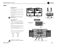
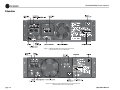
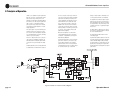
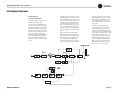
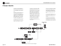
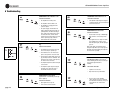
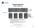
1
CH and CL Series CH1 CH2 CH4 Operation Manual CL1 CL2 CL4 Obtaining Other Language Versions: To obtain information in another language about the use of this product, please contact your local Crown Distributor. If you need assistance locating your local distributor, please contact Crown at 574-294-8000. This manual does not include all of the details of design, production, or variations of the equipment. Nor does it cover every possible situation which may arise during installation, operation or maintenance. The information provided in this manual was deemed accurate as of the publication date. However, updates to this information may have occurred. To obtain the latest version of this manual, please visit the Crown website at www.crownaudio.com. Trademark Notice: Crown, Crown Audio, Amcron, and BCA are registered trademarks of Crown International. Other trademarks are the property of their respective owners. Some models may be exported under the name Amcron.® ©2006 by Crown Audio® Inc., 1718 W. Mishawaka Rd., Elkhart, Indiana 46517-9439 U.S.A. Telephone: 574-294-8000 130808-8 1/06 CH and CL Series Power Amplifiers Important Safety Instructions IMPORTANT 1) 2) 3) 4) 5) 6) 7) 8) 9) 10) 11) 12) 13) 14) page 2 Read these instructions. Keep these instructions. Heed all warnings. Follow all instructions. Do not use this apparatus near water. Clean only with a dry cloth. Do not block any ventilation openings. Install in accordance with the manufacturer’s instructions. Do not install near any heat sources such as radiators, heat registers, stoves, or other apparatus (including amplifiers) that produce heat. Do not defeat the safety purpose of the polarized or grounding-type plug. A polarized plug has two blades with one wider than the other. A grounding-type plug has two blades and a third grounding prong. The wide blade or the third prong is provided for your safety. If the provided plug does not fit into your outlet, consult an electrician for replacement of the obsolete outlet. Protect the power cord from being walked on or pinched, particularly at plugs, convenience receptacles, and the point where they exit from the apparatus. Only use attachments/accessories specified by the manufacturer. Use only with a cart, stand, tripod, bracket, or table specified by the manufacturer, or sold with the apparatus. When a cart is used, use caution when moving the cart/apparatus combination to avoid injury from tip-over. Unplug this apparatus during lightning storms or when unused for long periods of time. Refer all servicing to qualified service personnel. Servicing is required when the apparatus has been damaged in any way, such as powersupply cord or plug is damaged, liquid has been spilled or objects have fallen into the apparatus, the apparatus has been exposed to rain or moisture, does not operate normally, or has been dropped. 15) WARNING: TO REDUCE THE RISK OF FIRE OR ELECTRIC SHOCK, DO NOT EXPOSE THIS APPARATUS TO RAIN OR MOISTURE. 16) DO NOT EXPOSE TO DRIPPING OR SPLASHING. DO NOT PLACE OBJECTS FILLED WITH LIQUID, SUCH AS VASES,ON THIS APPARATUS. TO PREVENT ELECTRIC SHOCK DO NOT REMOVE TOP OR BOTTOM COVERS. NO USER SERVICEABLE PARTS INSIDE. REFER SERVICING TO QUALIFIED SERVICE PERSONNEL. À PRÉVENIR LE CHOC ÉLECTRIQUE N’ENLEVEZ PAS LES COUVERCLES. IL N’Y A PAS DES PARTIES SERVICEABLE À L’INTÉRIEUR. TOUS REPARATIONS DOIT ETRE FAIRE PAR PERSONNEL QUALIFIÉ SEULMENT. TO COMPLETELY DISCONNECT THIS EQUIPMENT FROM THE AC MAINS, DISCONNECT THE POWER SUPPLY CORD PLUG FROM THE AC RECEPTACLE. THE MAINS PLUG OF THE POWER SUPPLY CORD SHALL REMAIN READILY OPERABLE. WATCH FOR THESE SYMBOLS: The lightning bolt triangle is used to alert the user to the risk of electric shock. The exclamation point triangle is used to alert the user to important operating or maintenance instructions. Commercial Audio Series amplifiers require Class 2 output wiring. MAGNETIC FIELD CAUTION! Do not locate sensitive high-gain equipment such as preamplifiers or tape decks directly above or below the unit. Because this amplifier has a high power density, it has a strong magnetic field which can induce hum into unshielded devices that are located nearby. The field is strongest just above and below the unit. If an equipment rack is used, we recommend locating the amplifier(s) in the bottom of the rack and the preamplifier or other sensitive equipment at the top. FCC COMPLIANCE NOTICE This device complies with part 15 of the FCC rules. Operation is subject to the following two conditions: (1) This device may not cause harmful interference, and (2) this device must accept any interference received, including interference that may cause undesired operation. CAUTION: Changes or modifications not expressly approved by the party responsible for compliance could void the user’s authority to operate the equipment. NOTE: This equipment has been tested and found to comply with the limits for a Class B digital device, pursuant to part 15 of the FCC Rules. These limits are designed to provide reasonable protection against harmful interference in a residential installation. This equipment generates, uses, and can radiate radio frequency energy and, if not installed and used in accordance with the instruction manual, may cause harmful interference to radio communications. However, there is no guarantee that interference will not occur in a particular installation. If this equipment does cause harmful interference to radio or television reception, which can be determined by turning the equipment off and on, the user is encouraged to try to correct the interference by one or more of the following measures: • Reorient or relocate the receiving antenna. • Increase the separation between the equipment and receiver. • Connect the equipment into an outlet on a circuit different from that to which the receiver is connected. • Consult the dealer or an experienced radio/TV technician for help. Operation Manual CH and CL Series Power Amplifiers DECLARATION of CONFORMITY Crown International, Inc. Issued By: FOR COMPLIANCE QUESTIONS ONLY: Crown International, Inc. 1718 W. Mishawaka Road Elkhart, Indiana 46517 U.S.A. Sue Whitfield 574-294-8289 [email protected] European Representative's Name and Address: Nick Owen 35, Bassets Field Thornhill Cardiff. South Glamorgen CF14 9UG United Kingdom Equipment Type: Commercial Audio Power Amplifiers Family Name: CH Series, CL Series Model Names: CH1, CH2, CH4, CL1, CL2, CL4 EMC Standards: EN 55103-1:1995 Electromagnetic Compatibility - Product Family Standard for Audio, Video, Audio-Visual and Entertainment Lighting Control Apparatus for Professional Use, Part 1: Emissions EN 55103-1:1995 Magnetic Field Emissions-Annex A @ 10 cm and 1 M EN 61000-3-2:1995+A14:2000 Limits for Harmonic Current Emissions (equipment input current ≤16A per phase) EN 61000-3-3:1995 Limitation of Voltage Fluctuations and Flicker in Low-Voltage Supply Systems Rated Current ≤16A EN 55022:1992 + A1: 1995 & A2:1997 Limits and Methods of Measurement of Radio Disturbance Characteristics of ITE: Radiated, Class B Limits; Conducted, Class B EN 55103-2:1996 Electromagnetic Compatibility - Product Family Standard for Audio, Video, Audio-Visual and Entertainment Lighting Control Apparatus for Professional Use, Part 2: Immunity EN 61000-4-2:1995 Electrostatic Discharge Immunity (Environment E2-Criteria B, 4k V Contact, 8k V Air Discharge) EN 61000-4-3:1996 Radiated, Radio-Frequency, Electromagnetic Immunity (Environment E2, criteria A) EN 61000-4-4:1995 Electrical Fast Transient/Burst Immunity (Criteria B) EN 61000-4-5:1995 Surge Immunity (Criteria B) EN 61000-4-6:1996 Immunity to Conducted Disturbances Induced by Radio-Frequency Fields (Criteria A) EN 61000-4-11:1994 Voltage Dips, Short Interruptions and Voltage Variation Safety Standard: EN 60065: 1998 Safety Requirements - Audio Video and Similar Electronic Apparatus I certify that the product identified above conforms to the requirements of the EMC Council Directive 89/336/EEC as amended by 92/31/EEC, and the Low Voltage Directive 73/23/EES as amended by 93/68/EEC. Signed Larry Coburn Title: Senior Vice President of Manufacturing Operation Manual The following applies to the CH 1, CH 2, CL 1 and CL 2 only. Due to line current harmonics, we recommend that you contact your supply authority before connection. page 3 CH and CL Series Power Amplifiers Table of Contents Important Safety Instructions .......................................................2 4 Advanced Features and Options .............................. 19 Declaration of Conformity ............................................................3 4.1 Protection Systems ..................................................................19 1 Welcome ..................................................... 5 4.1.1 Power Circuit Breaker .....................................................19 1.1 Features ...........................................................................5 4.1.2 Proportional-speed or 3-speed Fan ................................19 1.2 How to Use This Manual ..................................................5 4.2 Advanced Features ..................................................................19 2 Setup ......................................................... 6 4.2.1 BCA® (CH4 and CL4 Only) .............................................19 2.1 Unpack Your Amplifier .....................................................6 4.2.2 Switching Power Supply with PFC (CH4 and CL4 Only) .19 2.2 Install Your Amplifier .......................................................6 4.3 Options .....................................................................................19 2.3 Ensure Proper Cooling ....................................................6 4.3.1 Input Sensitivity ...............................................................19 2.4 Choose Input Wire and Connectors .................................7 4.3.2 Crown SST Modules .......................................................19 2.5 Choose Output Wire and Connectors ...............................7 4.3.3 Fault Monitoring ..............................................................21 2.6 Switch Settings ................................................................8 4.3.4 Precision Detented Level Controls ...................................22 2.7 Wire Your System ............................................................9 5 Principles of Operation ........................................ 23 2.7.1 Models CH1 & CH2 Stereo Mode............................9 5.1 CH1, CH2, CL1 and CL2 .........................................................23 2.7.2 Models CH1 & CH2 140V Bridge Mode .................9 5.2 CH4 and CL4 ...........................................................................25 . . 2.7.3 Model CH4 Stereo Mode ........................................10 5.2.1 Audio Signal Path ...........................................................25 2.7.4 Model CH4 Bridge Mode ........................................10 5.2.2 Power Supply Operation .................................................27 2.7.5 Models CL1 & CL2 Stereo Mode ............................11 6 Troubleshooting ................................................. 28 2.7.6 Models CL1 & CL2 Bridge Mode ...........................11 7 Specifications ................................................... 29 2.7.7 Model CL4 Stereo Mode .........................................12 8 AC Power Draw and Thermal Dissipation ................... 34 2.7.8 Model CL4 Bridge Mode ........................................12 9 Service ............................................................ 38 2.7.9 All Models: How to Parallel the Inputs 9.1 International and Canada Service ............................................38 in Stereo Mode ........................................................13 9.2 US Service ...............................................................................38 2.8 Connect to AC Mains .......................................................13 9.2.1 Service at a US Service Center ........................................38 2.9 Startup Procedure ............................................................13 9.2.2 Factory Service ...............................................................38 3 Operation .................................................... 14 9.2.3 Factory Service Shipping Instructions: ...........................38 3.1 Precautions ......................................................................14 9.2.4 Packing Instructions........................................................38 3.2 Indicators .........................................................................18 9.2.5 Estimate Approval............................................................38 3.3 Controls ...........................................................................18 9.2.6 Payment of Non-Warranty Repairs...................................38 10 Warranty ......................................................... 39 Crown Factory Service Information Form ............................................41 page 4 Operation Manual CH and CL Series Power Amplifiers Output Power Output Output Power Power at at 11 kHz kHz at at rated rated THD; THD; Stereo Stereo mode, mode, per per channel channel with with both both channels channels driven. driven. STEREO MODE MODE STEREO CH1 CH2 CH4 CL1 CL2 CL4 BRIDGE BRIDGE MODE MODE 2 Ohms 4 Ohms 8 Ohms 70V 4 Ohms 8 Ohms 140V 1400W 560W 975W 1800W* 450W 660W 1200W 450W 660W 1200W 275W 400W 600W 275W 400W 600W 300W 600W 1200W 900W 1320W 2800W 2400W 1100W 900W 1950W 1320W 3600W* 2400W 600W 1200W 2400W * ≥ 200VAC Line Voltage 1 Welcome Congratulations on your purchase of a Crown® CH or CL Series commercial power amplifier. The CH and CL Series is a complete family of amplifiers with a wide range of power output capabilities and output configurations. CH Series amplifiers can directly drive “constant voltage” lines, so you can avoid the expense of adding step-up transformers for distributed loudspeaker systems. CL Series amplifiers offer low-impedance compatibility for applications where high-power, low-impedance loads are the primary requirement. All CH and CL Series amplifiers feature Crown’s exclusive SST (System Solutions Topologies) expansion system. The SST expansion system makes it easy to tailor your amplifier to a specific application or to add future technology as it develops (see Section 4.3.2 for descriptions of available SSTs). Modern power amplifiers are sophisticated pieces of engineering capable of producing extremely high power levels. They must be treated with respect and correctly installed if they are to provide the many years of reliable service for which they were designed. Operation Manual In addition, CH and CL Series amplifiers include a number of features which require some explanation before they can be used to their maximum advantage. • CL Series includes high power 2-ohm operation, for jobs where low impedance is the only requirement. • A red five-way Fault LED for each channel blinks during amplifier power-up, and upon the following fault conditions: excessive heatsink temperature; transformer thermal protection; short at amplifier output; output stage non-operational. Please take the time to study this manual so that you can obtain the best possible service from your amplifier. 1.1 Features • The CH and CL Series amplifiers are designed specially for fixed installation, and include the following features: • • CH Series provides for both low impedance and high impedance loads, with the choice of 4/8 ohm or 70V operation for each channel. The output mode of each channel can be set independently, allowing unique or mismatched loads to be driven by each channel. CH Series includes a 70-Hz high-pass filter for each channel (when used in 70V mode) providing necessary low-frequency roll-off to eliminate saturation of constant voltage step-down transformers typically used in 70V distributed systems. • An RJ11 connector allows external circuits to monitor the status of the Fault circuit. • Detented level controls are located on the back panel for security, and allow for accurate level settings. • Barrier strip output connectors allow for quick easy connection regardless of the load, and accept up to 10 AWG crimp-on terminal forks. • SST modules provide flexible input options, such as onboard crossover configurations. • Stereo/Bridge switch allows conversion from Stereo mode to Bridge mode for higher-powered single-channel operation. • Advanced protection circuitry guards against: shorted outputs, open circuits, DC, mismatched loads, general overheating, high frequency overloads and internal faults. • Three Year, No-Fault, Fully-Transferable Warranty completely protects your investment and guarantees its specifications. 1.2 How to Use This Manual This manual provides you with the necessary information to safely and correctly setup and operate your amplifier. It does not cover every aspect of installation, setup or operation that might occur under every condition. For additional information, please consult Crown’s Amplifier Application Guide (available online at www.crownaudio.com), Crown Technical Support, your system installer or retailer. We strongly recommend you read all instructions, warnings and cautions contained in this manual. Also, for your protection, please send in your warranty registration card today. And save your bill of sale — it’s your official proof of purchase. page 5 CH and CL Series Power Amplifiers 2 Setup 2.1 Unpack Your Amplifier Please unpack and inspect your amplifier for any damage that may have occurred during transit. If damage is found, notify the transportation company immediately. Only you can initiate a claim for shipping damage. Crown will be happy to help as needed. Save the shipping carton as evidence of damage for the shipper’s inspection. We also recommend that you save all packing materials so you will have them if you ever need to transport the unit. Never ship the unit without the factory pack. YOU WILL NEED (not supplied): • Input wiring cables • Output wiring cables 2.2 Install Your Amplifier CAUTION: Before you begin, make sure your amplifier is disconnected from the power source, with the power switch in the “off” position and all level controls turned completely down (counterclockwise). Use a standard 19-inch (48.3 cm) equipment rack (EIA RS-310B). See Figure 2.1 for amplifier dimensions. You may also stack amps without using a cabinet. 2.3 Ensure Proper Cooling When using an equipment rack, close any open spaces in rack with blank panels. DO NOT block front or rear air vents. The side walls of the rack should be a minimum of two inches (5.1 cm) away from the amplifier sides, and the back of the rack should be a minimum of four inches (10.2 cm) from the amplifier back panel. For more information on cooling, please refer to the Crown Amplifier Application Guide, available online at www.crownaudio.com. Figure 2.2 illustrates standard amplifier airflow. NOTE: When transporting, amplifiers should be supported at both front and back. Rack for mounting amplifier (or a stable surface for stacking) WARNING: Before you start to set up your amplifier, make sure you read and observe the Important Safety Instructions found at the beginning of this manual. Figure 2.2 Airflow Figure 2.1 Mounting Dimensions page 6 Operation Manual CH and CL Series Power Amplifiers 2 Setup 2.4 Choose Input Wire and Connectors You have three choices of input connectors: 1/4-inch (6.35-mm) phone, 3-pin XLR, or barrier strip. You can also use either balanced or unbalanced wiring. Figure 2.3 shows balanced connector pin assignments for XLR and phone. Figure 2.4 shows unbalanced connector pin assignments for XLR and phone. Figure 2.5 shows barrier strip input wiring for a balanced signal. Both channels should be wired using a common center terminal for ground connection. NOTE: Custom wiring should only be performed by qualified personnel. Figure 2.3 Balanced Input Connector Wiring Figure 2.4 Unbalanced Input Connector Wiring Figure 2.5 Barrier Strip Input Wiring: Balanced Signal In 2.5 Choose Output Wire and Connectors Crown recommends using professionally constructed, highquality, two- or four-conductor, heavy gauge speaker wire and connectors. You may use terminal forks or bare wire for your output connectors (see Figure 2.7). CH and CL Series amplifier terminal strips accept up to 10 AWG terminal forks which fit over a #8 screw. To prevent the possibility of short circuits, wrap or otherwise insulate exposed loudspeaker cable and connectors. Also, a notouch cover, which covers the terminal strips, is provided to help prevent short circuits. To remove this cover, Figure 2.6 How to Remove the No-Touch Cover 2. SLIDE then PULL OFF 1. LOOSEN SCREWS 1. Loosen screws inside top and bottom holes of cover (see Figure 2.6). 2. Slide cover up or down, then pull it off away from the amplifier. Using the guidelines below, select the appropriate size of wire based on the distance from amplifier to speaker. Distance Wire Size up to 25 ft. 16 AWG 26-40 ft. 14 AWG 41-60 ft. 12 AWG Over 60 ft. 10 AWG 3. Reinstall no-touch cover to maintain safety. CAUTION: Never use shielded cable for output wiring. Operation Manual Figure 2.7 CL Series and CH4 Output Connector Wiring page 7 CH and CL Series Power Amplifiers 2 Setup 2.6 Switch Settings Proper wiring depends on how you configure your amplifier. The CH and CL Series offer various modes of operation: • Constant-voltage load • 4/8-ohm load • Stereo mode • Bridge-mono mode CH Series amplifiers only: Select 4/8 ohm or 70V operation as appropriate for your application and your amplifier. Select output operation by sliding the recessed Output Operation switches to the desired position as shown in Figure 2.9. Let’s explain each mode of operation Each output channel can be independently configured to drive either (1) 4/8-ohm loudspeakers, or (2) step-down transformers in a distributed “constant voltage” loudspeaker system. “Constant voltage” refers to 70V operation with models CH1, CH2 and CH4 only. Also, the amplifier can be configured for Dual or Bridge modes. Various combinations of these modes are possible. CH and CL Series amplifiers can be configured for either Stereo (dual channel) or Bridge (single mono channel) modes of operation. To switch your amplifier accordingly, set the recessed “Stereo/Bridge” switch to the desired setting as shown in Figure 2.8. Figure 2.8 Stereo/Bridge Mode Switch page 8 Channel Operation 4/8Ω 70V 4/8Ω 70V CH1 CH2 Model CH4 Models CH1 and CH2 Figure 2.9 Channel Operation Switches When the CH Series amplifier is set up for twochannel (Stereo mode) operation, it is possible to configure the output channels for either 4/8 ohm or 70V operation. WARNING: If Bridge mode is used with 70V output, the amplifier will actually deliver 140 volts. WARNING: The two Output Operation switches must be set to identical positions (4/8 ohm or 70V mode) when operating in Bridge mode. Never change switch positions with power turned on. CAUTION: Output Terminals are activated by selection of an output operation mode via the Output Operation switches. All other Output Terminals are inactive. For example, when 4/8 Ohm Operation is selected, the 70V connections are inactive, with no audio present at those Output Terminals. Figures 2.9 through 2.16 on the following pages show common ways to install CH and CL Series amplifiers in a sound system. Input and output terminals are located on the back panel. CAUTION: Always disconnect the AC power and turn the level controls off when making or breaking connections. This is very important when loudspeakers are connected because it reduces the chance of loud blasts that can cause loudspeaker damage. CAUTION: Never tie an amplifier’s outputs together directly while in Stereo mode. Never parallel them with the output of another amplifier. Such connections do not result in increased output power, but may cause overheating and premature activation of the protection circuitry. Note: The Channel 2 input jack and Input Level control are not defeated in Bridge mode. A signal feeding Channel 2 will work against the Channel 1 signal, and usually results in distortion and inefficient operation. Operation Manual CH and CL Series Power Amplifiers 2 Setup 2.7 Wire Your System 8 or 4 ohms 2.7.1 Models CH1 & CH2 Stereo Mode See Figure 2.10. In this example, Channel 1 is wired to a 4/8 ohm load and Channel 2 is wired to a 70V load. Make sure the Mode switch is set to the “Stereo” position. Set the Channel Operation Switch to 4/8 ohms on Channel1, and to 70V on Channel 2. INPUTS: Connect input wiring for each channel. OUTPUTS: Maintain proper polarity (+/–) on output connectors. • Connect Channel 1 positive speaker lead to Channel 1 4/8 ohm output terminal. • Connect Channel 1 negative speaker lead to Channel 1 negative terminal. • Connect Channel 2 positive transformer lead to either of Channel 2 70V+ output terminals. (The two 70V screws are in parallel offering more wiring flexibility). • Connect Channel 2 negative transformer lead to Channel 2 negative (–) terminal. 70 V Figure 2.10 Models CH1 & CH2 Wiring for Stereo Mode (Shown with No-Touch Cover Removed) Refer to Section 2.5 for output connector pin assignments. 2.7.2 Models CH1 & CH2 140V Bridge Mode See Figure 2.11. In this example, a 140V load is connected in Bridge Mono across the 70V+ terminals of Channel 1 and Channel 2. Both Channel Operation Switches are set to 70V. Make sure the Mode switch is set to the “Bridge” position. NOTE: When operating in Bridge-Mono mode, turn down (full CCW) the level control for Channel 2, as the Channel-1 level control works both channels. INPUTS: Connect input wiring to Channel 1. OUTPUTS: Connect positive (+) transformer lead to Channel 1 70V+ output terminal. Connect negative (–) transformer lead to Channel 2 70V+ output terminal. Refer to Section 2.5 for output connector pin assignments. Operation Manual Figure 2.11 Models CH1 & CH2 Wiring for 140V Bridge Mode (Shown with No-Touch Cover Removed) page 9 CH and CL Series Power Amplifiers 2 Setup 8 or 4 ohms 2.7.3 Model CH4 Stereo Mode See Figure 2.12. In this example, Channel 1 is wired to a 4/8 ohm load and Channel 2 is wired to a 70V load. 70 V Make sure the Mode switch is set to the “Stereo” position. Set the Channel Operation Switch to 4/8 ohms on Channel1, and to 70V on Channel 2. INPUTS: Connect input wiring for each channel. OUTPUTS: • Connect Channel 1 positive (+) speaker lead to Channel 1 positive (+) terminal of amp. • Connect Channel 1 negative (–) speaker lead to Channel 1 negative (–) output terminal of amp. • Connect Channel 2 positive (+) transformer lead to Channel 2 positive terminal of amp. • Connect Channel 2 negative (–) transformer lead to Channel 2 negative (–) output terminal of amp. Figure 2.12 Model CH4 Wiring for Stereo Mode (Shown with No-Touch Cover Removed) Refer to Section 2.5 for output connector pin assignments. 2.7.4 Model CH4 Bridge Mode See Figure 2.13. In this example, a 4/8-ohm load is connected in Bridge Mono across the positive terminals of Channel 1 and Channel 2. Both Channel Operation Switches are set to 4/8 ohms. Make sure the Mode switch is set to the “Bridge” position. NOTE: When operating in Bridge-Mono mode, turn down (full CCW) the level control for Channel 2, as the Channel-1 level control works both channels. + Mixer INPUTS: Connect input wiring to Channel 1. OUTPUTS: Connect positive (+) speaker lead to Channel 1 positive (+) terminal of amp. Connect negative (–) speaker lead to Channel 2 positive (+) terminal of amp. Do not connect to negative output terminals. Refer to Section 2.5 for output connector pin assignments. page 10 Figure 2.13 Model CH4 Wiring for Bridge Mode (Shown with No-Touch Cover Removed) Operation Manual CH and CL Series Power Amplifiers 2 Setup 2.7.5. Models CL1 & CL2 Stereo Mode See Figure 2.14. In this example, Channel 1 and Channel 2 are wired to 4/8-ohm speaker loads. Mixer Make sure the Mode switch is set to the “Stereo” position. INPUTS: Connect input wiring for each channel. OUTPUTS: • Connect Channel 1 positive (+) speaker lead to Channel 1 positive (+) terminal of amp. • Connect Channel 1 negative (–) speaker lead to Channel 1 negative (–) output terminal of amp. • Repeat similarly for Channel 2. Refer to Section 2.5 for output connector pin assignments. Figure 2.14 Models CL1 & CL2 Wiring for Stereo Mode (Shown with No-Touch Cover Removed) 2.7.6 Models CL1 & CL2 Bridge Mode See Figure 2.15. In this example, a 4/8-ohm load is connected in Bridge Mono across the positive terminals of Channel 1 and Channel 2. Make sure the Mode switch is set to the “Bridge” position. Mixer NOTE: When operating in Bridge-Mono mode, turn down (full CCW) the level control for Channel 2, as the Channel-1 level control works both channels. INPUTS: Connect input wiring to Channel 1. OUTPUTS: Connect positive (+) speaker lead to Channel 1 positive (+) terminal of amp. Connect negative (–) speaker lead to Channel 2 positive (+) terminal of amp. Do not connect to negative output terminals. Refer to Section 2.5 for output connector pin assignments. Operation Manual Figure 2.15 Models CL1 & CL2 Wiring for Bridge Mode (Shown with No-Touch Cover Removed) page 11 CH and CL Series Power Amplifiers 2 Setup 2.7.7. Model CL4 Stereo Mode See Figure 2.16. In this example, Channel 1 and Channel 2 are wired to 4/8-ohm speaker loads. Make sure the Mode switch is set to the “Stereo” position. INPUTS: Connect input wiring for each channel. OUTPUTS: • Connect Channel 1 positive (+) speaker lead to Channel 1 positive (+) terminal of amp. • Connect Channel 1 negative (–) speaker lead to Channel 1 negative (–) output terminal of amp. • Repeat similarly for Channel 2. Refer to Section 2.5 for output connector pin assignments. Figure 2.16 Model CL-4 Wiring for Stereo Mode (Shown with No-Touch Cover Removed) 2.7.8 Model CL4 Bridge Mode See Figure 2.17. In this example, a 4/8-ohm load is connected in Bridge Mono across the positive terminals of Channel 1 and Channel 2. Make sure the Mode switch is set to the “Bridge” position. NOTE: When operating in Bridge-Mono mode, turn down (full CCW) the level control for Channel 2, as the Channel-1 level control works both channels. INPUTS: Connect input wiring to CH1. OUTPUTS: Connect positive (+) speaker lead to Channel 1 positive (+) terminal of amp. Connect negative (–) speaker lead to Channel 2 positive (+) terminal of amp. Do not connect to negative output terminals. Refer to Section 2.5 for output connector pin assignments. page 12 Figure 2.17 Model CL4 Wiring for Bridge Mode (Shown with No-Touch Cover Removed) Operation Manual CH and CL Series Power Amplifiers 2 Setup 2.7.9 All Models: How to Parallel the Inputs in Stereo Mode There are three ways to feed the same signal to each amplifier channel: 1. Buy a “Y” cable. Plug the female end into your signal cable, and plug the split male ends into both amplifier inputs. 2. Feed your signal to the Channel-1 input (either barrier-block or XLR/Combo). Connect a jumper wire (Figure 2.18) between the barrier-block Channel-1 (+) screw terminal and the Channel-2 (+) screw terminal. Connect another jumper wire between the Channel-1 (–) screw terminal and the Channel-2 (–) screw terminal. 3. Feed your signal to the Channel-1 input screw terminals. CH1, CH2, CL1 only: Using a male XLR-to-male XLR cable, connect Channel-1 XLR connector to Channel-2 XLR connector. CH4, CL4 only: Using a stereo phone-to-phone cable, connect Channel 1 Combo connector to Channel 2 Combo connector. 2.9 Startup Procedure Use the following procedure when first turning on your amplifier: 2.8 Connect to AC Mains Connect your amplifier to the AC mains power source (power outlet) with the supplied AC power cordset. First, connect the IEC end of the cordset to the IEC connector on the amplifier; then, plug the other end of the cordset to the AC mains. 2. Turn down the level controls of the amplifier. WARNING: The third prong of this connector (ground) is an important safety feature. Do not attempt to disable this ground connection by using an adapter or other methods. 5. Turn up the Level controls on the amplifier until the desired loudness or power level is achieved. Amplifiers don’t create energy. The AC mains voltage and current must be sufficient to deliver the power you expect. You must operate your amplifier from an AC mains power source with not more than a 10% variation above or a 15% variation below the amplifier’s specified line voltage and within the specified frequency requirements (indicated on the amplifier’s back panel label). If you are unsure of the output voltage of your AC mains, please consult your electrician. 1. Turn down the level of your audio source. 3. Turn on the “Power” switch. The Power indicator should glow. 4. Turn up the level of your audio source to an optimum level. 6. Turn down the level of your audio source to its normal range. If you ever need to make any wiring or installation changes, don’t forget to disconnect the power cord. For help with determining your system’s optimum gain structure (signal levels) please refer to the Crown Amplifier Application Guide, available online at www.crownaudio.com. Figure 2.18 Jumper Positions to Parallel the Inputs Operation Manual page 13 CH and CL Series Power Amplifiers 3 Operation 3.1 Precautions Your amplifier is protected from internal and external faults, but you should still take the following precautions for optimum performance and safety: 1. Before use, your amplifier first must be configured for proper operation, including input and output wiring hookup. Improper wiring can result in serious operating difficulties. For information on wiring and configuration, please consult the Setup section of this manual or, for advanced setup techniques, consult Crown’s Amplifier Application Guide available online at www.crownaudio.com. 2. Use care when making connections, selecting signal sources and controlling the output level. The load you save may be your own! 3. Do not short the ground lead of an output cable to the input signal ground. This may form a ground loop and cause oscillations. page 14 4. WARNING: Never connect the output to a power supply, battery or power main. Electrical shock may result. 5. Tampering with the circuitry, or making unauthorized circuit changes may be hazardous and invalidates all agency listings. 6. Do not operate the amplifier with the red Clip LEDs constantly flashing. 7. Do not overdrive the mixer, which will cause clipped signal to be sent to the amplifier. Such signals will be reproduced with extreme accuracy, and loudspeaker damage may result. 8. Do not operate the amplifier with less than the rated load impedance. Due to the amplifier’s output protection, such a configuration may result in premature clipping and speaker damage. Remember: Crown is not liable for damage that results from overdriving other system components. Operation Manual CH and CL Series Power Amplifiers 3 Operation POWER CLIP FAULT FAULT CLIP SIGNAL “OFF” Position Power Indicator “ON” Position Power Switch SIGNAL Channel 1 Signal, Clip & Fault Indicators Channel 2 Signal, Clip & Fault Indicators Figure 3.1 CH and CL Series Front Panel Controls and Indicators Figure 3.2 Models CH1 & CH2 Back Panel Controls and Connectors (Shown with No-Touch Cover Removed) Operation Manual page 15 CH and CL Series Power Amplifiers 3 Operation Figure 3.3 Model CH4 Back Panel Controls and Connectors (Shown with No-Touch Cover Removed) Figure 3.4 Models CL1 & CL2 Back Panel Controls and Connectors (Shown with No-Touch Cover Removed) page 16 Operation Manual CH and CL Series Power Amplifiers 3 Operation 3-Speed Fan-On-Demand Figure 3.5 Model CL4 Back Panel Controls and Connectors (Shown with No-Touch Cover Removed) Operation Manual page 17 CH and CL Series Power Amplifiers 3 Operation The red Clip indicators turn on when distortion is audible in the amplifier output. 3.2 Indicators The front panel of a Contractor Series amplifier has several helpful indicators (Figure 3.6). The blue Power indicator shows that the amplifier has been turned on and has power. The green Signal Presence Indicators (SPI) illuminate when a signal (>–40 dBm) is present at the INPUT of the amplifier. This indicator is before the level control, so it can be used to troubleshoot wiring problems within a system. If the indicators are not lit, signal is not reaching the amplifier. POWER CLIP FAULT FAULT CLIP SIGNAL SIGNAL Figure 3.6 Indicators The red Fault indicators blink under five different conditions: 1. When the amplifier is first powered up, until the unit is ready for operation. 2. If the heatsinks reach a temperature above normal working limits. This can be caused by any number of abnormal conditions including but not limited to extremely low load impedance and/or inadequate cooling (see Section 1 for more information on cooling). 3. If the transformer (high-voltage power supply) thermal protection circuit is activated. Higher than rated output levels, excessively low-impedance loads and unreasonably high input signals can generate more heat in the power supply than in the output devices. This can overheat the power supply and activate the Fault protection circuit. 4. If amplifier output wires develop a short-circuit. This could be caused by a short anywhere along the circuit from the output connectors to the speakers, including shorted speaker drivers. 3.3 Controls The Enable switch is located on the front panel so you can easily turn the amplifier on and off. A 21-position Detented Level Control is provided for each channel. Level attenuation may be adjusted in steps. For security, the level controls are located on the back panel. A two-position Mode switch, located on the back panel, allows the selection of either Stereo or Bridge mode of operation. Stereo mode provides identical power output to each of the two amplifier output channels. Bridge mode combines the two amplifier output channels into a single mono channel with twice the voltage of a single stereo channel. It does this by bridging the outputs, and it requires special output wiring. Do NOT select Bridge mode without first making sure the amplifier has been wired in a BridgeMono configuration. For more information on wiring for Bridge mode, see the Setup section of this manual (Section 2), or consult your system installer. A two-position Output Operation switch (CH Series amplifiers only) allows the selection of either 4/8 ohm or 70V output from the amplifier. See Section 2 for more information about output operating modes. Fault Jack: This RJ11 jack (which looks like a phone jack) is located on the back panel. By attaching a signalling device to the Fault jack, you can monitor the amplifier’s Fault status from a remote location. See Section 4.3.3 for more information on fault monitoring and suggestions for signalling device circuity. A circuit breaker is provided to prevent the high-voltage power supplies from drawing excessive current. A Reset switch for the circuit breaker is provided on the back panel. If the circuit breaker trips, the Power indicator turns off. In this situation, turn off the Power switch and reset the circuit breaker. Then, turn the Power switch back on. If it trips again or the unit fails to operate properly, contact an authorized Crown Service Center or Crown Factory Service. When Bridge mode is selected, only the Channel 1 Level control and the Channel 1 Signal indicator will work. If the Channel 2 input is wired, the Channel 2 Level Control should be turned all the way down (counter/anti-clockwise) to prevent distortion. 5. If the amplifier output stage stops operating. page 18 Operation Manual CH and CL Series Power Amplifiers 4 Advanced Features and Options NOTE: For detailed information about these Crown amplifier features, please consult the Crown Amplifier Application Guide, available on the Crown website at www.crownaudio.com. 4.1 Protection Systems CH and CL Series amplifiers are protected against shorted, open or mismatched loads; overloaded power supplies; excessive temperature, chain destruction phenomena, input overload damage and high-frequency blowups. They also protect loudspeakers from input/output DC, large or dangerous DC offsets and turn-on/turn-off transients. 4.1.1 Power Circuit Breaker A back-panel push button is used to reset the circuit breaker that protects the power supply. Available in CH1, CH2, CL1 and CL2. 4.1.2 Proportional-speed or 3-speed Fan In the CH1, CH2, CL1 and CL2, a proportionalspeed fan directs the airflow through the amplifier for cooling. In the CH4 and CL4, a 3-speed Fan-OnDemand does the same thing. With their superior efficiency, BCA amplifiers can help to keep power requirements lower, while still providing excellent audio reproduction. And Crown BCA amplifiers are tough—easily handling very low (and highly reactive) load impedances, even under extreme conditions. In fact, Crown BCA amps have far out-performed competitive amplifiers in tests where the amplifier was run as much as 12 dB into clip for extended periods of time. 4.2.2 Switching Power Supply with PFC (CH4 and CL4 Only) Crown’s new Switching Power Supply with PFC provides a range of benefits over both non-switching and conventional switching power-supply designs. Typical non-switching power supplies require large transformers in order to produce the required power at the output stage. These transformers must be large to absorb the waste that occurs when operating at 50 to 60 Hz (standard AC supplied by the power company). 4.3.2 Crown SST Modules Crown optional SST (System Solution Topologies) modules were specially designed to improve the fidelity and versatility of your audio system. They feature a variety of professional signal routing and filtering capabilities, with active crossovers that allow the audio signal to be split and sent to auxiliary amplifiers. Your amplifier may have come with an SST module already factory-installed, or your choice of SST modules can be easily added to the amplifier by any authorized Crown Service Center. For information on wiring and configuration of amplifiers equipped with an optional Crown SST crossover module, please refer to the SST Crossover Reference Manual included in your literature package. Refer to the following descriptions for an overview of available Crown SST crossover modules. Crown plans to release additional accessory plug-in modules offering a range of advanced features and capabilities. Watch for new releases. By contrast, switching power supplies can operate with a much smaller (and lighter) transformer because they first convert the AC up to a much higher frequency, thereby reducing waste. 4.2 Advanced Features 4.2.1 BCA® (CH4 and CL4 Only) BCA (Balanced Current Amplifier) is Crown’s patented, cutting-edge technology that gets more power out of an amplifier with less waste than was ever before possible. A completely new adaptation of standard amplifier design, Crown’s BCA “switching” amplifier design provides for high output, exceptional reliability and nearly twice the efficiency of typical amplifier designs. While switching designs have been used successfully in other applications, these designs were never before suitable for use in precision, high-power audio amplifier applications. Crown’s BCA technology changes that, with a totally new paradigm for amplifier design that represents the future of professional amplifiers. Operation Manual 4.3 Options 4.3.1 Input Sensitivity Input Sensitivity is factory set to1.4V for each channel. With this setting, a 1.4V input signal will drive the amplifier to full power into an 8-ohm load when the Level Controls are turned to maximum. This setting works best when the amplifier is being driven by equipment with a +4 dBu output. Optionally, the Input Sensitivity for each channel can be individually set to either 0.775V or 26 dB. To have the input sensitivity changed on your amplifier, contact an authorized Crown Service Center page 19 CH and CL Series Power Amplifiers 4 Advanced Features and Options SST-SBSC-3632T SST-4622 This is a custom three-channel crossover network with CD-horn equalization and summed low-frequency output specifically designed for use with JBL® model 3632T ScreenArray® cinema speaker systems installed in cinemas, studio production and post-production environments. See Figure 4.1. This is a custom two-channel crossover network with equalization specifically designed for use with JBL® model 4622 ScreenArray® cinema speaker systems installed in cinemas, studio production and post-production environments. Features: • High-frequency signals are internally routed to the channel-one amplifier input, and mid-frequency signals are routed to the channel-two amplifier input. • Mono summing of low-frequency signals are routed from Output B to an external amplifier. • Neutrik® Combo jacks for balanced input connection. • Removable barrier block connectors for balanced output to other components. Features include: • Low-frequency signals are internally routed to the channel-one amplifier input, and high-frequency signals are routed to the channel-two amplifier input. • Barrier block connectors for balanced signal input. SST-3632 Like the SST-4622 but for the JBL 3632 cinema speaker systems. Additional features include: • SST-SBSC 4632T Like the SST-SBSC 3632T but for the JBL 4632T cinema speakers. Figure 4.1 SST-4622 Crossover Network Time correction via an all-pass analog delay ensures coherent summation through the crossover region, while maintaining optimal vertical polar response. SST-4632 Like the SST-3632 but for the JBL 4632 cinema speaker systems. page 20 Operation Manual CH and CL Series Power Amplifiers 4 Advanced Features and Options 4.3.3 Fault Monitoring The Fault (RJ-11) jack, which looks like a telephone plug, is located on the back of your CH or CL amplifier (Figure 4.2). It gives you an easy way to remotely monitor the amplifier’s fault status. To set up a circuit that will cause an LED to light whenever a fault status occurs, you can simply use the suggested circuit shown in Figure 4.3. When using this circuit, the LED will glow whenever the amplifier is in one of four states: a channel’s heatsink has reached its temperature limit, the transformer has reached its temperature limit, the amplifier has just been turned on and is in its turn-on-delay mode, or the amplifier is turned off. Figure 4.2 Location of Fault Jack If you choose to design your own circuit to interface this signal to your system, note that this RJ jack is polarity sensitive. Pin 2 must be grounded, and Pin 5 must be supplied with a positive voltage pull up (positive with respect to ground). Refer to Figure 4.4 for RJ jack pin assignments. The maximum signal that can be exposed to the fault jack is 35VDC and 10 mA. Best results are obtained with 10 mA LEDs. The mating connector for the RJ-11 jack contains 4 contact pins in a 6-slot case, as shown. For additional information please contact your local dealer or Crown Technical Support. Figure 4.3 Fault Status LED Circuitry Figure 4.4 RJ-11 Jack Wiring and Pin Assignments Operation Manual page 21 CH and CL Series Power Amplifiers 4 Advanced Features and Options 4.3.4 Precision Detented Level Controls A 21-position Precision Detented Level Control is provided for each channel. Level attenuation may be adjusted in precise steps as shown in Figure 4.5. For security, the level controls are located on the back panel. ATTENUATION in dB Detent 4/8 Ohm 70V 100V 0 (full CCW) -68.31 -72.90 -71.02 1 -67.54 -72.06 -70.26 2 -32.23 -36.61 -34.90 3 -25.46 -29.74 -28.00 4 -21.83 -25.87 -24.22 5 -19.23 -23.20 -21.58 6 -17.12 -20.94 -19.40 7 -15.36 -19.02 -17.53 8 -13.76 -17.22 -15.79 9 -12.28 -15.53 -14.20 10 -10.84 -13.90 -12.62 11 -9.51 -12.32 -11.16 12 -8.28 -10.87 -9.81 13 -7.09 -9.45 -8.45 14 -6.03 -8.11 -7.22 15 -4.92 -6.70 -5.94 16 -3.82 -5.26 -4.63 17 -2.62 -3.70 -3.21 18 -1.35 -1.90 -1.66 19 -0.01 -0.01 -0.01 20 (full CW) 0.00 0.00 0.00 Figure 4.5 Level-control Attenuation per Detent page 22 Operation Manual CH and CL Series Power Amplifiers 5 Principles of Operation 5.1 CH1, CH2, CL1 and CL2 For the sake of simplicity, only channel one of the amplifier is described. Signal is presented to the amplifier through one of three connectors when using the standard input module. Each channel is outfitted with a balanced XLR connector and a barrier strip. These connectors are wired in parallel, which allows daisy chaining when needed. The signal is then converted from balanced to unbalanced in the Balanced Input Stage where it also receives RFI protection. Signal then flows into the Variable Gain Stage where the rear-panel level controls are allowed to affect the gain. Following this stage, the signal is put under the control of a full-time compressor circuit comprised of a symmetrical window detector, a buffer amplifier, and the gating op amp which uses several small components to set the compressor’s attack and decay characteristics. The actual compressing is accomplished by an opto-isolator which affects the gain in the signal path. The signal then travels either through the HP filter module or is bypassed around it depending on the position of the channel operation switch. In the CH1 and CH2, with the switch set in the 70V position, the filter is enabled. The filter is an 18 dB-per-octave high-pass with a –3 dB rolloff at 70 Hz. This provides a measure of protection to step-down transformers used in distributed speakers installations. With the switch set in the 4/8 Ohm setting, the filter is bypassed. The signal next enters the main amplifier error amp where it is mixed with a small portion of the output signal in such a way as to control the amplifier’s overall output performance. Following the error amp is the LVA stage, where the low-voltage referenced signal gets translated to the output high-voltage rails. The last voltage amplifier, in conjunction with a bootstrap current source, drives both predrivers and the bias servo. The bias servo is mounted in such a way as to translate the output heatsink temperature into a controlled bias current to prevent thermal runaway and hold the amplifier’s notch distortion to a minimum. The predrivers provide enough signal to activate the drivers, which together operate in the class AB range. For the major output current requirements, the drivers feed the various numbers of paralleled output transistors which operate in a class B mode. This is referred to as the Triple-Deep Darlington Output Stages. The output transistors are protected by the Time Dependent Voltage & Current circuit. This circuit protects the devices from extending beyond their safe area of operation, but allows the devices to provide high bursts of peak power when needed. This amplifier output topology offers a good combination of low quiescent amplifier heating, great distortion performance at high powers, and relative simplicity, with impressive reliability and value. All output power is delivered through a channel-independent, dead front barrier block on the back panel. When the Channel Operation 70V 70V 4 / 8 OHMS – BALANCED INPUT STAGE Figure 5.1 Models CH1 & CH2 Circuit Block Diagram Operation Manual page 23 CH and CL Series Power Amplifiers 5 Principles of Operation switch is set to 4/8 Ohm, only the negative and 4/8 ohm connections on the barrier block have audio present. This provides power to low impedance speakers. When the Channel Operation switch is set to 70V, only the negative and 70V connections on the barrier block have audio present. This provides power to distributed speakers in a high-impedance “constantvoltage” application. The output relay, in conjunction with input signal mute circuit, assures a quiet turn-on and turn-off. In the event of an amplifier output failure, a triac will activate to turn off the offending channel to protect the speakers. The turn-on delay circuit functions to keep the output relay open until all the voltages are up and stable, both in the amplifier, and in all the components in the system ahead of the amplifier. Heatsink temperature is monitored by a thermal probe attached to the heatsink. As the tempera- ture rises, the probe sends a proportional current to the proportional speed fan circuit which starts the fan. Should the power transformer reach its maximum safe temperature, an internal thermal switch opens and the fan circuit turns on full speed to quickly cool down the amplifier. It also disconnects the load via the output relay, removing any output current and further speeding a cool-down cycle. This point is set both to protect speakers and to guard against nuisance tripping. Whenever the heatsinks or the transformer reach a maximum temperature, or during the normal turn on delay window, the front panel Fault Indicators will blink. An RJ11 modular jack is mounted on the back panel. Pins 2 and 5 are connected to an optoisolator which is always in a low-resistance state whenever the unit is on and operational. Should a fault be detected or should the amplifier lose AC power, the opto-isolator will change to a high resistance, allowing the user to remotely detect the status of the amplifier. The Signal Presence Indicators tap the signal chain just before the level controls and prior to the power amplifier chain. They are not amplifier output indicators and should only be used to indicate the presence of signal at the amplifier front end. The Clip Indicator is driven from the output of the compressor circuitry and lights to indicate the onset of audible distortion. The Power Indicator LED is driven from the low-voltage supply. A positive and negative regulator form the ±15volt power supplies. Add to that the main transformer, a full-wave bridge rectifier, and high energy electrolytic to form the main power supply. They are protected by the front-panel line circuit breaker and controlled by the front-panel power switch. BALANCED INPUT STAGE Figure 5.2 Models CL1 & CL2 Circuit Block Diagram page 24 Operation Manual CH and CL Series Power Amplifiers 5 Principles of Operation 5.2 CH4 and CL4 5.2.1 Audio Signal Path For the sake of simplicity, only channel one of the audio signal path is described. Signal is presented to the CH4/CL4 through one of three connectors when using the standard input module. Each channel is outfitted with a balanced XLR/phone jack, and a barrier strip. These connectors are wired in parallel, which allows daisy chaining when needed. The signal is then converted from balanced to unbalanced in the Balanced Input Stage where it also receives RFI protection. Signal then flows into the Variable Gain Stage where the front panel level controls are allowed to affect the gain. Following this stage, the signal goes through a gain stage that allows for the various positions of the sensitivity settings. The signal is then put under the control of a full-time compressor circuit comprised of a symmetrical window detector, a buffer amplifier, and the gating op amp which uses several small components to set the compressor’s attack and decay characteristics. The actual compressing is accomplished by an opto-isolator that affects the gain in the signal path. Next, the signal enters a 32-kHz 7th-Order Gaussian Low-Pass Filter. This filter prevents the modulator stage and the output filter (both described below) from receiving signals that are too high. Without the 32-kHz filter, the modulator would be unable to process signals that are too high and the output filter would not yield the proper frequency response behavior. The Gaussian filter type is unique in that it has minimal ringing and excellent phase response so even a high-order filter such as this one does not adversely affect the sonic excellence of the product. In the CH4, the signal then travels either through the HP filter module or is bypassed around it depending on the position of the channel operation switch. With the switch set in the 70V position, the filter is enabled. The filter is an 18 dB-per-octave high-pass with a –3-dB rolloff at 70 Hz. This provides a measure of protection to step-down transformers used in distributed speakers installations. With the switch set in the 4/8-Ohm setting, the filter is bypassed. The power is delivered to the load cables through the output connector panel which consists of one of several options. Figure 5.3 Model CH4 Circuit Block Diagram Operation Manual page 25 CH and CL Series Power Amplifiers 5 Principles of Operation The signal next enters the main amplifier error amp where it is mixed with a small portion of the output voltage and current in such a way as to control the amplifier’s overall output performance. Following the error amp is the modulator stage where the audio signal is compared to an extremely accurate 250-kHz triangle waveform. Comparators output a Pulse Width Modulated (PWM) string of pulses at 250 kHz that vary in width depending on the level of the input signal. These strings of pulses, one for the positive side and one for the negative side, are connected to the output stage via optocouplers. The signals from the optos are then passed to gate drivers that amplify the pulses to the level required to drive output devices. The driven output devices are now able to produce PWM pulses that have an output voltage from the negative high-voltage rail (–Vcc) to the positive high-voltage rail (+Vcc). This output voltage is always the same (2 * Vcc) but the width of the pulses is still dependent on the level of the input signal. The positive and negative output PWM pulses then pass through inductors and are summed together. Summing the output signals through inductors reconstructs the audio signal, amplified to the desired level. There is a small amount of ripple on the output that is at double the switching frequency (500 kHz). The amplified audio signal is then passed through an output filter that removes the residual ripple voltage. Protection for the output devices is performed by a very precise pulse-by-pulse current limiter circuit that operates each time the output devices switch. The current limiting is “flat” meaning that, regardless of the output voltage, the output current always limits at a certain value. The turn-on delay circuitry functions to keep the modulators turned off (which keeps the outputs from switching) until all supplies are up and stable. Thermal probes monitor Heatsink temperatures and power transformer temperature. As the temperatures rise, the probes send a proportional voltage to the fan control circuit and the Thermal Limit Control (TLC) circuit. The fan Figure 5.4 Model CL4 Circuit Block Diagram page 26 Operation Manual CH and CL Series Power Amplifiers 5 Principles of Operation normally runs at very low speed when the amplifier is idling or when it is being used for low to moderate duty work. If the amplifier is delivering large amounts of power into low impedance loads, the heatsinks or transformer may heat up enough to increase the speed of the fan to medium and possibly to high speed. If the temperature continues to increase, the TLC circuit uses the compressor to reduce the gain of the input stage and thus reduce the power dissipated by the amplifier. As a further protective measure, if the temperature continues to rise (due to blocked airflow for example), the amplifier will stop running and keep the fan on high speed to quickly bring the temperature back to an operational level. If a signal presented at the input of the amplifier will not be passed through to the output, the Fault LED will blink to get your attention. The turn-on delay, for example, will cause each channel’s LED to blink because the amplifier remains in standby for a few seconds before it allows audio output. An RJ11 modular jack is mounted on the back panel. Pins 2 and 5 are connected to an optoisolator that is always in a low-resistance state whenever the unit is on and happy. Should a fault be detected or should the amplifier lose AC power, the opto-isolator will change to a high resistance, allowing the user to remotely detect the status of the amplifier. The Signal Presence Indicators tap the signal chain just before the level controls and prior to the power amplifier chain. They are not amplifier output indicators and should only be used to indicate the presence of signal to the amplifier front end. Operation Manual The Clip indicators are driven from the output of the compressor circuitry and light to indicate the onset of audible distortion. The Power indicator LED is driven from the low-voltage supply. 5.2.2 Power Supply Operation AC power enters the amplifier through a power cord equipped with an IEC (unplugable) connector. It then is passed through the EMI filter. Circuits that use switching technology will normally send a small amount of high-frequency noise back down the power cord and into the power distribution system. This noise must be removed in order to sell the unit in certain parts of the world. Since the CH4/CL4 is a worldwide product, the EMI filter removes this noise so that it does not exit the box. The power then enters the Power Factor Correction (PFC) Boost stage. This stage is what allows the CH4/CL4 to be plugged into any outlet in the world without any modifications to the amplifier. The PFC stage uses switching power supply technology to take whatever AC line voltage comes in, convert it to DC and boost it to 400 Volts. The circuit also uses intelligence to draw the current from the line sinusoidally and in phase with the line voltage. This reduces the load on the power companies and also allows the amplifier to pull more peak power from the power source (the outlet). The power is drawn in small amounts 62,500 times each second and is used to provide power to the isolation stage and to fill the large energy reservoir capacitors. The power then goes to the “buck” isolation stage. This stage takes the 400 Volt PFC voltage and, again using switching power supply technology, converts it down (“bucks” it down) to the level needed to power the audio output stage. The isolation stage also satisfies a safety requirement by providing isolation, using a transformer, between the AC mains power and the power that is delivered to the speakers. The isolation stage moves power 125,000 times each second from the primary to the secondary to power the audio output stage and keep its large energy reservoir capacitors full. In order to keep the power supply controllers, protection circuits, and the audio signal path components powered, another switching power supply is used, this one also running at 125 kHz. This one is also a “buck” type supply in that it takes voltage from the 400 Volt PFC bus and converts it down to the low voltages needed. This circuit also uses a transformer to provide safety isolation. Like the audio signal path parts of the amplifier, there are many ways that the power supply protects itself. Part of the start-up time delay mentioned above occurs while the power supply is ramping up all of its voltages (soft-start) so that large inrush currents are avoided. Current limiters and over-current detectors are used to protect the power supply output devices. The power supply will also detect severe brownouts and shut off the supply until the brown-out is over if the line voltage is drastically less than normal. page 27 CH and CL Series Power Amplifiers 6 Troubleshooting CONDITION: Power indicator is off. CONDITION: Fault indicator is on. POSSIBLE REASON POSSIBLE REASON: • The amplifier has lost AC power. • • The amplifier’s Power switch is off. • The amplifier is not plugged into the power receptacle. • The power supply circuit breaker has tripped. Verify that input levels and output impedances are within safe ranges. Turn off the Power switch and reset the circuit breaker. Then, turn the Power switch back on. If it trips again or the unit fails to operate properly, contact an authorized Crown Service Center. CONDITION: Distorted sound. POSSIBLE REASON: • Load is wired incorrectly or Dual/Bridge mode switch is set incorrectly. Check both. • Input signal level is too high. Turn down your amplifier level controls, or turn down the input signal, until the clip light goes out. CONDITION: Fault indicator is flashing. POSSIBLE REASONS: • The amplifier has just been powered up and is not ready for operation yet. • The heatsinks are too hot. Ensure adequate cooling. Remove excessive loads. • The transformer (high-voltage power supply) thermal protection is activated. Turn down the Level controls or the input signal. Remove excessive loads. • The amplifier output wires have developed a short circuit. • The amplifier output stage has stopped operating. If so, return the unit to a Crown Authorized Service Center. CONDITION: No input signal. (Signal indicator is not flashing even though audio is applied). POSSIBLE REASON: page 28 • Input signal level is very low. • Level controls are turned down. The amplifier output stage has stopped operating. Refer the unit to an authorized Crown Service Center. Note: If the signal sounds distorted even though the Clip LED is off, the input signal is distorted. Check gain staging and output levels of the mixer or preamp. CONDITION: No sound, even though the amp has power. Power LED is on without flashing and the amp is receiving an input signal. Signal indicator is flashing. POSSIBLE REASON: • Speakers not connected. • Open circuit due to speaker failure. • There is a short on the amplifier output. First disconnect your speakers from the affected channel(s) one by one to determine if one of the loads is shorted. Operation Manual CH and CL Series Power Amplifiers 7 Specifications The following specifications apply to all models in Dual 8/4 ohm mode with 8-ohm loads unless otherwise specified. Minimum Guaranteed Power CH1 CH2 CH4 450W 275W 300W 660W 400W 600W 1,400W 1,200W 600W 1,200W 1 kHz at rated THD 4 ohms 8 ohms 140V 900W 600W 1,320W 1,200W 2,800W 2,400W 2,400W Performance CH1 CH2 CH4 ± 0.1 dB ± 0.1 dB ± 0.25 dB ± 15° ± 15° ± 15° 120V/60 Hz Units, Dual mode, per channel, both channels driven 1 kHz at rated THD 2 ohms 4 ohms 8 ohms 70V 120V/60 Hz Units, Bridge mono mode Frequency Response (at 1 watt, 20 Hz - 20 kHz) Phase Response (at 1 watt, 20 Hz - 20 kHz) Signal to Noise Ratio below rated 1 kHz power (A-weighted) > 105 dB > 105 dB > 100 dB Total Harmonic Distortion (THD) at rated 1 kHz power, 20 Hz to 20 kHz < 0.5% < 0.5% < 0.5% Intermodulation Distortion (IMD) 60 Hz and 7 kHz at 4:1, from rated power to 30 dB below rated power at 8 ohms < 0.1% < 0.1% < 0.5% Damping Factor (8 ohm), 10 Hz to 400 Hz Crosstalk (below rated power, 20 Hz to 20 kHz) *at 10 kHz > 600 > 600 > 1000 > 50 dB > 50 dB > 50 dB* Common Mode Rejection (CMR), 20 Hz to 1 kHz > 40 dB > 40 dB > 40 dB DC Output Offset (Shorted input) ± 10 mV ± 10 mV ± 10 mV Input Impedance nominally balanced, nominally unbalanced 20 kilohms, 10 kilohms 20 kilohms, 10 kilohms 20 kilohms, 10 kilohms Load Impedance (Note: Safe with all types of loads) Stereo Bridge Mono 4/8 and 16 ohm (70V) 8/16 and 32 ohms(140V) 4/8 and 8 ohm (70V), 8/16 and 16 ohms (140V) 4/8 and 4 ohm (70V) 8/16 and 8 ohm (140V) 30.5 dB 34.0 dB 32.1 dB 34.0 dB 34.0 dB 34.0 dB Required AC Mains (voltages ± 10%) 100V, 7.6A, 60 Hz 120V, 6.3A, 60 Hz 230-240V, 3.5A, 60 Hz 100V, 11.4A, 60 Hz 120V, 9.5A, 60 Hz 230-240V, 5.0A, 60 Hz 100V, 8.5A, 50/60 Hz 120V, 7.1A, 50/60 Hz 230-240V, 3.7A, 50/60 Hz Cooling Proportional speed fan Proportional speed fan 3-speed Fan-On-Demand 19 in. (48.3 cm) x 5.25 in. (13.34 cm) x 12.25 in. (31.11 cm) 19 in. (48.3 cm) x 5.25 in. (13.34 cm) x 12.25 in. (31.11 cm) 19 in. (48.3 cm) x 5.25 in. (13.34 cm) x 16.25 in*. (36.56 cm)* Voltage Gain (at maximum level setting), 1 kHz, 1.4V sensitivity 4/8 Ohm Operation 70V Operation Dimensions: Width, Height, Depth Net Weight, Shipping Weight Operation Manual 40.6 lb (18.4 kg), 46.6 lb (21.1 kg) 48.3 lb (21.9 kg), 54.3 lb (24.6 kg) * CH4 depth is 17.5 in. (14.45 cm) from back of front rack ears to back of speaker-terminals cover. 33.3 lb (15.1 kg), 39.3 lb (17.8 kg) page 29 CH and CL Series Power Amplifiers 7 Specifications The following specifications apply to all models in Dual 8/4 ohm mode with 8-ohm loads unless otherwise specified. Minimum Guaranteed Power CL1 CL2 CL4 560W 450W 275W 975W 660W 400W 1,400W 1,200W 600W 1,100W 900W 1,950W 1,320W 2,800W 2,400W 120V/60 Hz Units, Dual mode, per channel, both channels driven 1 kHz at rated THD 2 ohms 4 ohms 8 ohms 120V/60 Hz Units, Bridge mono mode 1 kHz at rated THD 4 ohms 8 ohms Performance Frequency Response (at 1 watt, 20 Hz - 20 kHz) Phase Response (at 1 watt, 10 Hz - 20 kHz) CL1 CL2 CL4 ± 0.1 dB ± 0.1 dB ± 0.25 dB ± 15° ± 15° ± 15° > 105 dB > 105 dB > 100 dB Total Harmonic Distortion (THD) at rated 1 kHz power, 20 Hz to 20 kHz < 0.5% < 0.5% < 0.5% Intermodulation Distortion (IMD) 60 Hz and 7 kHz at 4:1, from rated power to 30 dB below rated power at 8 ohms < 0.1% < 0.1% < 0.5% Signal to Noise Ratio below rated power (A-weighted) Damping Factor (8 ohm), 10 Hz to 400 Hz > 600 > 600 > 1000 Crosstalk (below rated power, 20 Hz to 20 kHz) *at 10 kHz > 50 dB > 50 dB > 50 dB* Common Mode Rejection (CMR), 20 Hz to 1 kHz > 40 dB > 40 dB > 40 dB DC Output Offset (Shorted input) Input Impedance nominally balanced, nominally unbalanced Load Impedance (Note: Safe with all types of loads) Stereo Bridge Mono Voltage Gain (at maximum level setting), 1 kHz, 1.4V sensitivity 4/8 Ohm Operation ± 10 mV ± 10 mV ± 10 mV 20 kilohms, 10 kilohms 20 kilohms, 10 kilohms 20 kilohms, 10 kilohms 2/4/8 ohm 4/8/16 ohm 2/4/8 ohm 4/8/16 ohm 2/4/8 ohm 4/8/16 ohm 30.5 dB 32.1 dB 34.0 dB Required AC Mains (voltages ± 10%) 100V, 7.6A, 60 Hz 120V, 6.3A, 60 Hz 230-240V, 3.5A, 60 Hz 100V, 11.4A, 60 Hz 120V, 9.5A, 60 Hz 230-240V, 5.0A, 60 Hz 100V, 8.5A, 50/60 Hz 120V, 7.1A, 50/60 Hz 230-240V, 3.7A, 50/60 Hz Cooling Proportional speed fan Proportional speed fan 3-speed Fan-On-Demand 19 in. (48.3 cm) x 5.25 in. (13.34 cm) x 12.25 in. (31.11 cm) 19 in. (48.3 cm) x 5.25 in. (13.34 cm) x 12.25 in. (31.11 cm) 19 in. (48.3 cm) x 5.25 in. (13.34 cm) x 16.25 in.* (36.56 cm)* Dimensions: Width, Height, Depth Net Weight, Shipping Weight 32.6 lb (14.78 kg), 38.6 lb (17.48 kg) 40.3 lb (18.28 kg), 46.3 lb (20.98 kg) 33.3 lb (15.1 kg), 39.3 (17.8 kg) * CL4 depth is 17.5 in. (14.45 cm) from back of front rack ears to back of speaker-terminals cover. page 30 Operation Manual CH and CL Series Power Amplifiers 7 Specifications Figure 7.1 Models CH1 & CH2 Frequency Response (Typical) +2 8ohm 4ohm +0 Figure 7.2 Model CL1 & CL2 Frequency Response (Typical) d B r -2 -4 -6 20 50 100 200 500 1k 2k 5k 10k 20k FREQUENCY (Hz) Figure 7.3 Models CH1, CH2, CL1 & CL2 Output Impedance (Typical) (CH1, CH2 Set To 4/8 Ohm Mode) Operation Manual page 31 CH and CL Series Power Amplifiers Figure 7.4 Models CH4 & CL4 Frequency Response (Typical) Figure 7.5 Models CH1, CH2, CL1 & CL2 Damping Factor (Typical) (CH1, CH2 Set To 4/8 Ohm Mode) page 32 Operation Manual CH and CL Series Power Amplifiers Figure 7.6 Models CH4 & CL4 Damping Factor (Typical) Figure 7.7 Models CH4 & CL4 Output Impedance (Typical) Operation Manual page 33 CH and CL Series Power Amplifiers 8 AC Power Draw and Thermal Dissipation This section provides detailed information about the amount of power and current drawn from the AC mains by CH and CL amplifiers and the amount of heat produced under various conditions. The calculations presented here are intended to provide a realistic and reliable depiction of the amplifiers. The following assumptions or approximations were made: • The amplifier’s available channels are loaded, and full power is being delivered. • Amplifier efficiency at standard 1-kHz power is estimated to be 65% for CH1, CH2, CL1 and CL2 models, and 77% for CH4 and CL4 models. • Typical quiescent power draw is approximately 60 watts for CH1, CH2, CL1 and CL2 models, and 140 watts for CH4 and CL4 models. Here are the equations used to calculate the data presented in Figures 8.1, 8.2 and 8.3: The value used for Amplifier Efficiency is 0.65 for CH1, CH2, CL1 and CL2 models, and 0.77 for CH4 and CL4 models (these values are listed in the previous column). The following equation converts power draw in watts to current draw in amperes: • When running at full speed, typical power draw for the internal fan is 12 watts for all models. • Quiescent thermal dissipation is related. • The estimated duty cycles take into account the typical crest factor for each type of source material. • Duty cycle of pink noise is 50%. • Duty cycle of highly compressed rock ‘n’ roll midrange is 40%. The value used for Power Factor is 0.83 for CH1, CH2, CL1 and CL2 models, and 0.98 for CH4 and CL4 models. The Power Factor variable is needed to compensate for the difference in phase between the AC mains voltage and current. The following equation is used to calculate thermal dissipation: • Duty cycle of rock ‘n’ roll is 30%. • Duty cycle of background music is 20%. • Duty cycle of continuous speech is 10%. • Duty cycle of infrequent, short duration paging is 1%. The value used for Amplifier Inefficiency is 0.35 (1.00–0.65) for CH1, CH2, CL1 and CL2 models, and 0.23 (1.00–0.77) for CH4 and CL4 models.The factor 3.415 converts watts to btu/hr. Thermal dissipation in btu is divided by the constant 3.968 to get kcal. If you plan to measure output power under real-world conditions, the following equation may also be helpful: page 34 Operation Manual CH and CL Series Power Amplifiers 8 AC Power Draw and Thermal Dissipation Figure 8.1 Model CH1 Power Draw, Current Draw and Thermal Dissipation at Various Duty Cycles Figure 8.2 Model CH2 Power Draw, Current Draw and Thermal Dissipation at Various Duty Cycles Operation Manual page 35 CH and CL Series Power Amplifiers 8 AC Power Draw and Thermal Dissipation Figure 8.3 Model CH4 Power Draw, Current Draw and Thermal Dissipation at Various Duty Cycles Figure 8.4 Model CL1 Power Draw, Current Draw and Thermal Dissipation at Various Duty Cycles page 36 Operation Manual CH and CL Series Power Amplifiers 8 AC Power Draw and Thermal Dissipation CL2 LOAD 2 OHMS DUAL / 4 OHMS BRIDGE AC Mains Duty Power Cycle Draw (Watts) 1560 50% 1260 40% 30% 960 660 20% 10% 360 Current Draw(Amps) 100-120 230-240 15.6 7.8 12.6 9.6 6.6 6.3 4.8 3.3 3.6 1.8 AC Mains Thermal Dissipation Power Draw btu/hr kcal/hr (Watts) 1998 504 1075 872 1639 413 669 1281 323 466 922 232 563 8 OHMS DUAL / 16 OHMS BRIDGE 4 OHMS DUAL / 8 OHMS BRIDGE 142 263 Current Draw(Amps) Thermal Dissipation 100-120 230-240 10.8 8.8 6.7 4.7 5.4 4.4 3.4 2.4 1419 1175 993 690 btu/hr kcal/hr 296 260 235 174 2.6 1.3 448 113 AC Mains Power Draw (Watts) 675 552 429 306 183 Current Draw(Amps) Thermal Dissipation 100-120 230-240 6.7 5.5 4.3 3.1 1.8 3.4 2.8 2.2 btu/hr 940 793 646 kcal/hr 237 200 163 1.6 1.4 499 352 126 89 Figure 8.5 Model CL2 Power Draw, Current Draw and Thermal Dissipation at Various Duty Cycles Figure 8.6 Model CL4 Power Draw, Current Draw and Thermal Dissipation at Various Duty Cycles Operation Manual page 37 CH and CL Series Power Amplifiers 9 Service Crown amplifiers are quality units that rarely require servicing. Before returning your unit for service, please contact Crown Technical Support to verify the need for servicing. This unit has very sophisticated circuitry which should only be serviced by a fully trained technician. This is one reason why each unit bears the following label: CAUTION: To prevent electric shock, do not remove covers. No user serviceable parts inside. Refer servicing to a qualified technician. Complete the Crown Audio Factory Service Information form, in the back of this manual, when returning a Crown product to the factory or authorized service center. The form must be included with your product inside the box or in a packing slip envelope securely attached to the outside of the shipping carton. Do not send this form separately. 9.1 International and Canada Service Service may be obtained from an authorized service center. (Contact your local Crown/Amcron representative or our office for a list of authorized service centers.) To obtain service, simply present the bill of sale as proof of purchase along with the defective unit to an authorized service center. They will handle the necessary paperwork and repair. Remember to transport your unit in the original factory pack. 9.2 US Service Service may be obtained in one of two ways: from an authorized service center or from the factory. You may choose either. It is important that you have your copy of the bill of sale as your proof of purchase. 9.2.1 Service at a US Service Center This method usually saves the most time and effort. Simply present your bill of sale along with the defective unit to an authorized service center to obtain service. They will handle the necessary paperwork and repair. Remember to transport the unit in the original factory pack. A list of authorized service centers in your area can be obtained from Crown Factory Service, or online from http://www.crownaudio.com/support/servcent.htm. page 38 9.2.2 Factory Service Crown accepts no responsibility for non-serviceable product that is sent to us for factory repair. It is the owner’s responsibility to ensure that their product is serviceable prior to sending it to the factory. Serviceable product list is available at http://crownweb.crownintl.com/crownrma/. For more information, please contact us direct. 9.2.4 Packing Instructions Important: These instructions must be followed. If they are not followed, Crown Audio, Inc. assumes no responsibility for damaged goods and/or accessories that are sent with your unit. A Service Return Authorization (SRA) is required for product being sent to the factory for repair. An SRA can be completed online at www.crownaudio.com/support/ factserv.htm. If you do not have access to the web, please call Crown’s Customer Service at 574.294.8200 or 800.342.6939 extension 8205. 2. Do not ship any accessories (manuals, cords, hardware, etc.) with your unit. These items are not needed to service your product. We will not be responsibility for these items. For warranty service, we will pay for ground shipping both ways in the United States. Contact Crown Customer Service to obtain prepaid shipping labels prior to sending the unit. Or, if you prefer, you may prepay the cost of shipping, and Crown will reimburse you. Send copies of the shipping receipts to Crown to receive reimbursement. Your repaired unit will be returned via UPS ground. Please contact us if other arrangements are required. 9.2.3 Factory Service Shipping Instructions: 1. Service Return Authorization (SRA) is required for product being sent to the factory for service. Please complete the SRA by going to www.crownaudio.com/support/factserv.htm. If you do not have access to our website, call 1.800.342.6939, extension 8205 and we'll create the SRA for you. 2. See packing instructions that follow. 3. Ship product to: CROWN AUDIO FACTORY SERVICE 1718 W MISHAWKA RD. ELKHART, IN 46517 4. Use a bold black marker and write the SRA number on three sides of the box. 5. Record the SRA number for future reference. The SRA number can be used to check the repair status. 1. Fill out and include the Crown Audio Factory Service Information sheet in the back of this manual. 3. When shipping your Crown product, it is important that it has adequate protection. We recommend you use the original pack material when returning the product for repair. If you do not have the original box, please call Crown at 800.342.6939 or 574.294.8210 and order new pack material. See instructions for “foam-in-place” shipping pack. (Do not ship your unit in a wood or metal cabinet.) 4. If you provide your own shipping pack, the minimum recommended requirements for materials are as follows: a. 275 P.S.I. burst test, Double-Wall carton that allows for 2-inch solid Styrofoam on all six sides of unit or 3 inches of plastic bubble wrap on all six sides of unit. b. Securely seal the package with an adequate carton sealing tape. c. Do not use light boxes or “peanuts”. Damage caused by poor packaging will not be covered under warranty. Using your 'foam-in-place' shipping pack Note: The foam-in-place packing is molded so that there is only one correct position for your product. 3. Reset center cushion down over top of product's chassis. The foam-in-place packing was molded to accommodate different chassis depth sizes. If your product's chassis does not completely fill the foamin-place cavity, you may use a soft but solid packing material (such as paper or bubble wrap) behind the chassis. 4. Enclose the completed Crown Audio Factory Service Information form (or securely attach it to the outside of carton) and re-seal the shipping pack with a sturdy carton sealing tape. 9.2.5 Estimate Approval Approval of estimate must be given within 90 days after being notified by Crown Audio Inc. Units still in the possession of Crown after 90 days of the estimate will become the property of Crown Audio Inc. 9.2.6 Payment of Non-Warranty Repairs Payment on out-of-warranty repairs must be received within 90 days of the repair date. Units unclaimed after 90 days become the property of Crown Audio Inc. If you have any questions, please contact Crown Factory Service. Crown Factory Service 1718 W. Mishawaka Rd., Elkhart, Indiana 46517 U.S.A. Telephone: 574.294.8200 800.342.6939 (North America, Puerto Rico, and Virgin Islands only) Facsimile: 574.294.8301 (Technical Support) 574.294.8124 (Factory Service) Internet: http://www.crownaudio.com 1. Open carton and lift center cushion leaving both end-cushions in place. 2. Carefully place your product with the product's front panel facing the same direction as arrows indicate. Operation Manual CH and CL Series Power Amplifiers 10 Warranty UNITED STATES & CANADA SUMMARY OF WARRANTY 3 AR YE Crown International, 1718 West Mishawaka Road, Elkhart, Indiana 46517-4095 U.S.A. warrants to you, the ORIGINAL PURCHASER and ANY SUBSEQUENT OWNER of each NEW Crown product, for a period of three (3) years from the date of purchase by the original purchaser (the “warranty period”) that the new Crown product is free of defects in materials and workmanship. We further warrant the new Crown product regardless of the reason for failure, except as excluded in this Warranty. ITEMS EXCLUDED FROM THIS CROWN WARRANTY This Crown Warranty is in effect only for failure of a new Crown product which occurred within the Warranty Period. It does not cover any product which has been damaged because of any intentional misuse, accident, negligence, or loss which is covered under any of your insurance contracts. This Crown Warranty also does not extend to the new Crown product if the serial number has been defaced, altered, or removed. WHAT THE WARRANTOR WILL DO We will remedy any defect, regardless of the reason for failure (except as excluded), by repair, replacement, or refund. We may not elect refund unless you agree, or unless we are unable to provide replacement, and repair is not practical or cannot be timely made. If a refund is elected, then you must make the defective or malfunctioning product available to us free and clear of all liens or other encumbrances. The refund will be equal to the actual purchase price, not including inter- Operation Manual est, insurance, closing costs, and other finance charges less a reasonable depreciation on the product from the date of original purchase. Warranty work can only be performed at our authorized service centers or at the factory. Warranty work for some products can only be performed at our factory. We will remedy the defect and ship the product from the service center or our factory within a reasonable time after receipt of the defective product at our authorized service center or our factory. All expenses in remedying the defect, including surface shipping costs in the United States, will be borne by us. (You must bear the expense of shipping the product between any foreign country and the port of entry in the United States including the return shipment, and all taxes, duties, and other customs fees for such foreign shipments.) FROM ANY DEFECT IN THE NEW CROWN PRODUCT. THIS INCLUDES ANY DAMAGE TO ANOTHER PRODUCT OR PRODUCTS RESULTING FROM SUCH A DEFECT. SOME STATES DO NOT ALLOW THE EXCLUSION OR LIMITATIONS OF INCIDENTAL OR CONSEQUENTIAL DAMAGES, SO THE ABOVE LIMITATION OR EXCLUSION MAY NOT APPLY TO YOU. HOW TO OBTAIN WARRANTY SERVICE DESIGN CHANGES You must notify us of your need for warranty service within the warranty period. All components must be shipped in a factory pack, which, if needed, may be obtained from us free of charge. Corrective action will be taken within a reasonable time of the date of receipt of the defective product by us or our authorized service center. If the repairs made by us or our authorized service center are not satisfactory, notify us or our authorized service center immediately. DISCLAIMER OF CONSEQUENTIAL AND INCIDENTAL DAMAGES YOU ARE NOT ENTITLED TO RECOVER FROM US ANY INCIDENTAL DAMAGES RESULTING WARRANTY ALTERATIONS No person has the authority to enlarge, amend, or modify this Crown Warranty. This Crown Warranty is not extended by the length of time which you are deprived of the use of the new Crown product. Repairs and replacement parts provided under the terms of this Crown Warranty shall carry only the unexpired portion of this Crown Warranty. We reserve the right to change the design of any product from time to time without notice and with no obligation to make corresponding changes in products previously manufactured. LEGAL REMEDIES OF PURCHASER THIS CROWN WARRANTY GIVES YOU SPECIFIC LEGAL RIGHTS, YOU MAY ALSO HAVE OTHER RIGHTS WHICH VARY FROM STATE TO STATE. No action to enforce this Crown Warranty shall be commenced after expiration of the warranty period. THIS STATEMENT OF WARRANTY SUPERSEDES ANY OTHERS CONTAINED IN THIS MANUAL FOR CROWN PRODUCTS. 12/01 page 39 CH and CL Series Power Amplifiers 10 Warranty 3 AR YE WORLDWIDE EXCEPT USA & CANADA SUMMARY OF WARRANTY Crown International, 1718 West Mishawaka Road, Elkhart, Indiana 46517-4095 U.S.A. warrants to you, the ORIGINAL PURCHASER and ANY SUBSEQUENT OWNER of each NEW Crown1 product, for a period of three (3) years from the date of purchase by the original purchaser (the “warranty period”) that the new Crown product is free of defects in materials and workmanship, and we further warrant the new Crown product regardless of the reason for failure, except as excluded in this Warranty. 1 Note: If your unit bears the name “Amcron,” please substitute it for the name “Crown” in this warranty. ITEMS EXCLUDED FROM THIS CROWNWARRANTY This Crown Warranty is in effect only for failure of a new Crown product which occurred within the Warranty Period. It does not cover any product which has been damaged because of any intentional misuse, accident, negligence, or loss which is covered under any of your insurance contracts. This Crown Warranty also does not extend to the new Crown product if the serial number has been defaced, altered, or removed. WHAT THE WARRANTOR WILL DO We will remedy any defect, regardless of the reason for failure (except as excluded), by repair, replacement, or refund. We may not elect refund page 40 unless you agree, or unless we are unable to provide replacement, and repair is not practical or cannot be timely made. If a refund is elected, then you must make the defective or malfunctioning product available to us free and clear of all liens or other encumbrances. The refund will be equal to the actual purchase price, not including interest, insurance, closing costs, and other finance charges less a reasonable depreciation on the product from the date of original purchase. Warranty work can only be performed at our authorized service centers. We will remedy the defect and ship the product from the service center within a reasonable time after receipt of the defective product at our authorized service center. HOW TO OBTAIN WARRANTY SERVICE You must notify your local Crown importer of your need for warranty service within the warranty period. All components must be shipped in the original box. Corrective action will be taken within a reasonable time of the date of receipt of the defective product by our authorized service center. If the repairs made by our authorized service center are not satisfactory, notify our authorized service center immediately. DISCLAIMER OF CONSEQUENTIAL AND INCIDENTAL DAMAGES YOU ARE NOT ENTITLED TO RECOVER FROM US ANY INCIDENTAL DAMAGES RESULTING FROM ANY DEFECT IN THE NEW CROWN PRODUCT. THIS INCLUDES ANY DAMAGE TO ANOTHER PRODUCT OR PRODUCTS RESULTING FROM SUCH A DEFECT. WARRANTY ALTERATIONS No person has the authority to enlarge, amend, or modify this Crown Warranty. This Crown Warranty is not extended by the length of time which you are deprived of the use of the new Crown product. Repairs and replacement parts provided under the terms of this Crown Warranty shall carry only the unexpired portion of this Crown Warranty. DESIGN CHANGES We reserve the right to change the design of any product from time to time without notice and with no obligation to make corresponding changes in products previously manufactured. LEGAL REMEDIES OF PURCHASER No action to enforce this Crown Warranty shall be commenced after expiration of the warranty period. THIS STATEMENT OF WARRANTY SUPERSEDES ANY OTHERS CONTAINED IN THIS MANUAL FOR CROWN PRODUCTS. 7/01 Operation Manual CH and CL Series Power Amplifiers PRODUCT REGISTRATION Crown International 1718 W. Mishawaka Rd. Elkhart, IN 46517-9439 Phone: 574-294-8000 Fax: 574-294-8329 www.crownaudio.com Online registration is also available at http://crownweb.crownintl.com/webregistration When this form is used to register your product, it may be mailed or faxed. Crown International 1718 W Mishawaka Rd Elkhart IN 46517 Fax: 574-294-8329 Please note that some information is required. Incomplete registrations will not be processed. * Indicates required information. CUT ON THIS LINE OWNER'S INFORMATION - PLEASE PRINT * First name: ______________________ Middle initial: _____ * Last name: ________________________________ Company: _________________________________________________________________________________ * Mailing address: ____________________________________________________________________________ * City: ____________________________* State: ___________________________* Zip Code: ________________ * Country: __________________________ E-mail address: ___________________________________________ * Phone # (include area code): ___________________________ Fax #: __________________________________ PRODUCT INFORMATION * MODEL ie. MA3600VZ, CE1000A, PCC160 ________________________________ ________________________________ ________________________________ ________________________________ * SERIAL # ____________________ ____________________ ____________________ ____________________ PURCHASE DATE mo/day/yr ______ /_____ /_____ ______ /_____ /_____ ______ /_____ /_____ ______ /_____ /_____ Product purchased from: ___________________________ City: __________________ State: ___________ Comments: ____________________________________________________________________________________ _____________________________________________________________________________________________ _____________________________________________________________________________________________ Operation Manual page 41 CH and CL Series Power Amplifiers THIS PAGE INTENTIONALLY LEFT BLANK page 42 Operation Manual CH and CL Series Power Amplifiers Crown Audio Factory Service Information Shipping Address: Crown Audio Factory Service, 1718 W. Mishawaka Rd., Elkhart, IN 46517 PLEASE PRINT CLEARLY SRA #: __________________(If sending product to Crown factory service.) Model: _________________________________ Serial Number: _____________________ Purchase Date: ________________ PRODUCT RETURN INFORMATION Individual or Business Name: ___________________________________________________________________________________________________________________________________________________________________________ Phone #: __________________________________________________ _________________________________________________________ Fax #: ________________________________________ E-Mail: Street Address (please, no P.O. Boxes): ___________________________________________________________________________________________________________________________________________________________________________ City: __________________________________________ State/Prov: ________________________________ Postal Code: _________________ Country: _____________________ Nature of problem: ___________________________________________________________________________________________________________________________________________________________________________ ___________________________________________________________________________________________________________________________________________________________________________ ___________________________________________________________________________________________________________________________________________________________________________ Other equipment in your system: ___________________________________________________________________________________________________________________________________________________________________________ If warranty is expired, please provide method of payment. Proof of purchase may be required to validate warranty. PAYMENT OPTIONS I have open account payment terms. Purchase order required. PO#____________________________________________________ COD Credit Card (Information below is required; however if you do not want to provide this information at this time, we will contact you for the information when your unit is repaired). Credit card information: Type of credit card: Master Card Type of credit card account: Visa Personal/Consumer American Express Discover Business/Corporate Card # ______________________________________________ Exp. date: _____________ * Card ID #: __________________________ * Card ID # is located on the back of the card following the credit card #, in the signature area. On American Express, it may be located on the front of the card. This number is required to process the charge to your account. If you do not want to provide it at this time, we will call you to obtain this number when the repair of your unit is complete. Name on credit card: ____________________________________________________________________________ Billing address of credit card: __________________________________________________________________________ __________________________________________________________________________ __________________________________________________________________________ Operation Manual page 43