1
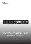
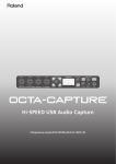
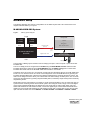
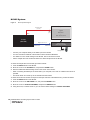
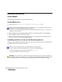
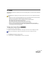
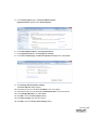
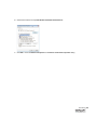
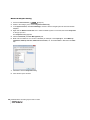
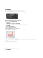
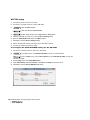
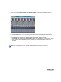
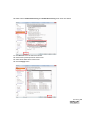
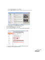
User’s Guide IMPORTANT NOTES • Unfortunately, it may be impossible to restore the contents of data that was stored on a storage device (e.g., hard disk) once it has been lost. Roland Corporation assumes no liability concerning such loss of data. • To avoid disturbing others nearby, try to keep the unit’s volume at reasonable levels. You may prefer to use headphones, so you do not need to be concerned about those around you. • In the interest of product improvement, the specifications and/or contents of this package are subject to change without prior notice. • The explanations in this manual include illustrations that depict what should typically be shown by the display. Note, however, that your unit may incorporate a newer, enhanced version of the system (e.g., includes newer sounds), so what you actually see in the display may not always match what appears in the manual. • It is forbidden by law to make an audio recording, video recording, copy or revision of a third party’s copyrighted work (musical work, video work, broadcast, live performance, or other work), whether in whole or in part, and distribute, sell, lease, perform, or broadcast it without the permission of the copyright owner. • Do not use this product for purposes that could infringe on a copyright held by a third party. We assume no responsibility whatsoever with regard to any infringements of third-party copyrights arising through your use of this product. • ASIO is a trademark and software of Steinberg Media Technologies GmbH. • Microsoft product screen shot(s) reprinted with permission from Microsoft Corporation. • Cakewalk is a registered trademark of Cakewalk, Inc. in the United States. • SONAR is a trademark of Cakewalk, Inc. • Company names and product names appearing in this document are registered trademarks or trademarks of their respective owners. Copyright © 2012 ROLAND CORPORATION All rights reserved. No part of this publication may be reproduced in any form without the written permission of ROLAND CORPORATION. Roland, REAC are either registered trademarks or trademarks of Roland Corporation in the United States and/or other countries. Table of Contents SONAR™ REAC Recording System . . . . . . . . . . . . . . . . . . . . . . . . . . . . . . . . . . . . . . . . . . . 5 Hardware and software requirements. . . . . . . . . . . . . . . . . . . . . . . . . . . . . . . . . . 5 REAC system requirements . . . . . . . . . . . . . . . . . . . . . . . . . . . . . . . . . . . . . . 5 When Making Important Recordings . . . . . . . . . . . . . . . . . . . . . . . . . . . . . . . 6 Computer requirements . . . . . . . . . . . . . . . . . . . . . . . . . . . . . . . . . . . . . . . . . 8 Software and driver updates . . . . . . . . . . . . . . . . . . . . . . . . . . . . . . . . . . . . 10 Hardware setup . . . . . . . . . . . . . . . . . . . . . . . . . . . . . . . . . . . . . . . . . . . . . . . . . 11 M-480/M-400/M-380 System . . . . . . . . . . . . . . . . . . . . . . . . . . . . . . . . . . . . 11 M-300 System . . . . . . . . . . . . . . . . . . . . . . . . . . . . . . . . . . . . . . . . . . . . . . . 13 M-200i System . . . . . . . . . . . . . . . . . . . . . . . . . . . . . . . . . . . . . . . . . . . . . . . 14 S-1608 System. . . . . . . . . . . . . . . . . . . . . . . . . . . . . . . . . . . . . . . . . . . . . . . 16 S-4000 System. . . . . . . . . . . . . . . . . . . . . . . . . . . . . . . . . . . . . . . . . . . . . . . 17 Software installation . . . . . . . . . . . . . . . . . . . . . . . . . . . . . . . . . . . . . . . . . . . . . . 18 Install SONAR . . . . . . . . . . . . . . . . . . . . . . . . . . . . . . . . . . . . . . . . . . . . . . . 18 Install REAC driver . . . . . . . . . . . . . . . . . . . . . . . . . . . . . . . . . . . . . . . . . . . . 18 Installing the Driver to Use as the Monitoring Device. . . . . . . . . . . . . . . . . . 18 PC setup . . . . . . . . . . . . . . . . . . . . . . . . . . . . . . . . . . . . . . . . . . . . . . . . . . . . . . . 19 To Open the Control Panel . . . . . . . . . . . . . . . . . . . . . . . . . . . . . . . . . . . . . 19 Configure Windows . . . . . . . . . . . . . . . . . . . . . . . . . . . . . . . . . . . . . . . . . . . 20 FA-66 setup . . . . . . . . . . . . . . . . . . . . . . . . . . . . . . . . . . . . . . . . . . . . . . . . . 28 QUAD-CAPTURE / OCTA-CAPTURE setup . . . . . . . . . . . . . . . . . . . . . . . . 29 VS-700 setup . . . . . . . . . . . . . . . . . . . . . . . . . . . . . . . . . . . . . . . . . . . . . . . . 30 SONAR setup. . . . . . . . . . . . . . . . . . . . . . . . . . . . . . . . . . . . . . . . . . . . . . . . 32 About the REAC Driver Control Panel . . . . . . . . . . . . . . . . . . . . . . . . . . . . . 39 Notes on word clock, synchronization and latency. . . . . . . . . . . . . . . . . . . . 41 Troubleshooting . . . . . . . . . . . . . . . . . . . . . . . . . . . . . . . . . . . . . . . . . . . . . . . . . 43 Table of Contents •• 3 • • • • 4 •• SONAR REAC Recording System User’s Guide • • • • SONAR™ REAC Recording System Hardware and software requirements REAC system requirements This recording system can be used with the following Roland REAC Systems: • • • Roland V-Mixing System (2) S-1608 (and/or S-4000S) at stage position M-480, M-400, M-380 or M-300 (S-4000D Splitter required) at FOH position M-200i Roland S-1608 System S-1608 at stage position S-0816 at FOH position for audio outputs to console Roland S-4000D REAC Splitter Roland S-4000 System S-4000S at stage position S-4000S with SO-AES4 (AES/EBU Option Card) at FOH position for audio outputs to a console Roland S-4000D REAC Splitter Hardware and software requirements •• 5 • • • • When Making Important Recordings Because the recording system using the REAC driver consists of multiple elements (the computer, the operating system, various drivers), there can be various reasons why recording does not occur correctly. Some possibilities are that a specific element might not be working correctly, the overall system might have insufficient performance, the settings might not be appropriate, the system was not operated correctly, or some other reason. In addition, the recording system will be affected by the environment in which it is located (the power supply, sound pressure level, vibration, temperature, etc.), and these factors may cause it to operate incorrectly. Please carefully read the following cautions. Check carefully before you make an important recording. On the day before the actual recording or during the rehearsal, check to make sure that recording occurs correctly. Use an additional recording device to record simultaneously (Backup recording). As a precaution against dropouts or stoppages on the main system during recording, be sure to use an additional recording device to make a simultaneous recording. Verify the settings of your computer, Windows, the drivers, and SONAR. Be sure to check that the settings have been made correctly as described in this document. If the settings are incorrect, recording will not occur correctly. Depending on the performance of your computer, it may be necessary to adjust the buffer size of the REAC driver. Depending on your computer's hardware, on its version of Windows, and on the software that is installed, it may be necessary to make other settings in addition to those described in this document. Check the free space on the hard disk before recording. Before you record, make sure that the hard disk has sufficient free space, taking into account relevant factors such as the recording time, the number of tracks you'll be recording, and the sample rate. Be sure to format the recording hard disk before you record. If the hard disk is significantly fragmented, recording may stop because the hard disk cannot provide sufficient performance. Do not use other software during recording. Recording might not occur correctly if you use other software (including Windows Store apps for Windows 8). Do not place the computer in a hot location. Depending on the temperature of the location in which the computer is placed, you may need to take measures to prevent overheating. 6 •• SONAR REAC Recording System User’s Guide • • • • Do not place the computer in locations of high sound pressure levels, such as near a speaker. High sound pressure levels may cause the hard disk to malfunction, causing recording to stop. Ideally, the computer should be placed in a separate room from the PA speakers (the source of the sound). However if the computer must be placed in the same room, take measures such as keeping it at a distance from the speakers, placing sound-absorbing material such as acoustic baffles or blankets between the computer and the speakers, or place commercially available sheets of vibrational insulating material between the floor and the computer. Use an uninterruptable power supply (UPS) to provide power to the computer and the audio interface. If the power supply should fail, you'll need to stop recording, save the data, and shut down the computer completely. Be sure to disconnect the Ethernet cables connected to the REAC system before you shut down the computer, while the computer is powered-off, and before you restart. If you start up, restart, or shut down the computer while the REAC system is connected to your computer via Ethernet, the REAC system may experience problems such as dropouts. Do not connect the Ethernet cable until the operating system (Windows) has finished starting up. You must turn the FA-66's DIGITAL IN button OFF before you power-on the REAC system. After the REAC system has started up, turn the FA-66's DIGITAL IN button ON. Never connect the computer to the Internet etc. after making the settings described in this document. Later in the procedure described here, we will be disabling functions such as Windows Update and security settings to allow recording to occur without dropouts. This means that the computer will be in a state of lowered security, making it vulnerable to computer viruses or other malicious software. If you will be connecting a storage device such as an external hard disk or a USB flash drive to the computer, or inserting media such as a CD-ROM or DVD-ROM into the computer after making the settings described in this document, use a different computer to perform a virus check on that storage device or media before you connect or insert it. Later in the procedure described here, we will be disabling functions such as Windows Update and security settings to allow recording to occur without dropouts. This means that the computer will be in a state of lowered security, making it vulnerable to computer viruses or other malicious software. When monitoring the sound from the REAC system via the recording system, there will be approximately one second of latency. Since additionally-recorded audio tracks will need to be offset relative to previously-recorded tracks, this system is not suitable for use in multitrack recording (overdubbing). * Please be aware that Roland Corporation and Cakewalk Inc. USA accept no responsibility, neither financial nor other, for any damages, whether direct or indirect, that may occur due to any malfunction or any loss of recorded data. Hardware and software requirements •• 7 • • • • Computer requirements The Roland REAC Driver is currently designed to work on PC computers only. It has not been tested, nor is it approved for Mac computers running any version of Windows (under Bootcamp or Parallels). PC Operating system Windows 8 (32-bit or 64-bit) Windows 7 SP1 (32-bit or 64-bit) Processor speed Intel Core i5 2.6 GHz or higher RAM 4 GB or more Ethernet port speed Gigabit Ethernet/CAT5e only Graphics 1280 x 800, 16-bit color or higher Recommended: 1920 x 1080, 24-bit color or higher Audio hard disk type RAID 0 with (2) SATA drives or SSD (*5) Other (*1) IEEE 1394 port, USB 2.0 port, DVD-ROM drive Monitoring device (*2) Roland QUAD-CAPTURE Roland OCTA-CAPTURE Cakewalk FA-66 Cakewalk VS-700 R Other hardware (*3) Roland Digital Snake or V-Mixing system Roland CAT5e cables (supplied with Digital Snakes) Gigabit Ethernet switch (optional) SONAR version (*4) SONAR X2 PRODUCER / STUDIO / ESSENTIAL Other software Adobe Reader Table 1. REAC system requirements SONAR REAC Recording System requirements are based on the system requirements for SONAR X2. There are a number of other variables that may affect performance; including differences in hardware design, system configuration and overall combination of software applications that are installed. (*1) • • • The monitoring device cannot be used with a USB 3.0 port that is not compatible with USB 2.0 specification. If the monitoring device does not work correctly when connected to a USB 3.0 port, you will need to connect it to a USB 2.0 port. Even if connected to a USB 3.0 port, the performance of the monitoring device will not change. (*2) REAC Driver version 2.0 provides legacy support for Edirol FA-66 and Cakewalk SPS-66 hardware units. We cannot guarantee the operation of devices that are not listed in the “Monitoring device” section. (*3) System components will vary depending on your V-Mixing System configuration. 8 •• SONAR REAC Recording System User’s Guide • • • • (*4) We cannot guarantee operation with software other than those listed in the “SONAR version” section. REAC Driver version 2.0 does not provide legacy support for SONAR 7 Producer, SONAR 8 Producer, SONAR 8.5 Producer, SONAR X1 Producer, and SONAR X1 Producer Expanded. (*5) Separately from the hard disk in which Windows and SONAR are installed, you will need a dedicated hard disk that is used only for recording. Hard Disk Free Space Required for Recording The free hard disk space required for recording will depend on the number of channels being recorded, the sample rate, and the recording time as shown in the following table. Make sure that you have plenty of space. Number of recording channels Sample rate Recording one hour Recording two hours 8 44.1 kHz 4 GB 8 GB 48 kHz 4 GB 8 GB 96 kHz 8 GB 16 GB 44.1 kHz 8 GB 16 GB 48 kHz 8 GB 16 GB 96 kHz 16 GB 32 GB 44.1 kHz 11 GB 22 GB 48 kHz 12 GB 24 GB 96 kHz 24 GB 48 GB 44.1 kHz 15 GB 30 GB 48 kHz 16 GB 32 GB 96 kHz 32 GB 64 GB 44.1 kHz 18 GB 36 GB 48 kHz 20 GB 40 GB 96 kHz 40 GB 80 GB 16 24 32 40 Table 2. Hard Disk Free Space Required for Recording Note: If the free space on the hard disk is completely used up during recording, the recorded result will not be saved correctly. Hardware and software requirements •• 9 • • • • Note: While under most conditions, a computer similar to the above will permit normal operation of the product, Roland cannot guarantee compatibility solely on these factors. This is due to numerous variables that may influence the processing environment, such as differences in motherboard design and the particular combination of other devices involved. Caution: Do not operate the PC on an unstable or unlevel surface or near equipment that produces excessive vibrations. Software and driver updates Before you use the REAC recording system, please update SONAR and your other software and drivers to the latest versions. Download the SONAR updater from www.cakewalk.com. 10 •• SONAR REAC Recording System User’s Guide • • • • Hardware setup The following diagrams are common configurations for the REAC System with a PC. Please refer to the diagram that best reflects your system. M-480/M-400/M-380 System Figure 1. V-Mixing System Diagram Stage S-1608 (SLAVE) Computer S-1608 (SLAVE) REAC B REAC A Network cable (Cat. 5e) SPLIT/BACKUP M-480/M-400/M-380 (MASTER) SONAR + REAC driver + Audio interface driver LAN port Digital audio clock DIGITAL OUT IEEE1394/USB2.0 Audio Interface (44.1 kHz or 48 kHz) DIGITAL IN FOH Headphones The preceding V-Mixing system consists of two S-1608(s) (16 inputs x 2 and 8 outputs x 2) and an M-480/ M-400/M-380. The two S-1608(s) must be configured as the SLAVE using the REAC MODE switches and the M-480/ M-400/M-380 must be configured as the FOH (MASTER) using the REAC Config option on the M-480/ M-400/M-380. Please refer to the M-480/M-400/M-380 manual for more details. The REAC driver can receive up to 40 channels of audio data from the REAC split port on the M-480/M-400/ M-380. You can check the SPLIT OUT audio source assignment on the M-400/M-380 LCD by pressing the M-400/M-380 [SYSTEM] button, followed by the [REAC CONFIG] button and finally the [SPLIT] button. The audio source assignment of the SPLIT port of the M-480 is the same settings as REAC port A, You can check and change the assignment by pressing the [PATCHBAY] button, followed by the [OUTPUT] button and finally the [REAC A] button. Digital Audio Clock Synchronization is necessary to avoid monitoring problems, such as noises and gaps. To synchronize the monitoring device with the REAC system when using the FA-66, simply connect the digital output of the M-480/M-400/M-380 to the digital input of the FA-66 with an optical cable. When using the QUAD-CAPTURE/OCTA-CAPTURE/VS-700R, connect the digital output of the M-480/M-400/M-380 to the digital input of the QUAD-CAPTURE/OCTA-CAPTURE/VS-700R with a coaxial cable. If using the VS-700R, open VS-700R IO Editor and choose DIGITAL 1 in SYNC SOURCE and COAXIAL in DIGITAL 1 INPUT. Hardware setup •• 11 • • • • Figure 2. V-Mixing System Diagram (S-4000S-3208 and M-480/M-400/M-380 connection) Stage Computer S-4000S-3208 (SLAVE) SONAR + REAC driver + Audio interface driver Network cable (Cat. 5e) SPLIT/BACKUP M-480/M-400/M-380 (MASTER) LAN port Audio Interface (44.1 kHz or 48 kHz) Digital audio clock DIGITAL OUT IEEE1394/USB2.0 DIGITAL IN FOH Headphones Note: The M-480/M-400/M-380 and S-4000S-3208 connection requires M-400 firmware version 1.501 or later and S-4000S firmware version 2.010 or later. The preceding V-Mixing system (Figure 2.) consists of an S-4000S-3208 (32 inputs and 8 outputs) and an M-480/M-400/M-380. The S-4000S must be configured as the SLAVE using the REAC MODE switches and the M-480/M-400/ M-380 must be configured as the FOH (MASTER) using the REAC Config option on the M-480/M-400/ M-380. Please refer to the M-480/M-400/M-380 manual for more details. The sample rate of the monitoring device must be set to the same sample rate as the M-480/M-400/M-380. You can check the sample rate of the M-480/M-400/M-380 by following these steps: 1. Push the SYSTEM button. 2. On screen, look for INTERNAL SAMPLING FREQ that will tell you the sample rate of the M-480/M-400/ M-380. Note: The REAC Driver Control Panel also displays the current REAC sample rate when connected. The REAC driver can receive up to 40 channels of audio data from the REAC split port on the M-480/M-400/ M-380. You can check the SPLIT OUT audio source assignment on the M-400/M-380 LCD by pressing the M-400/M-380 [SYSTEM] button, followed by the [REAC CONFIG] button and finally the [SPLIT] button. The audio source assignment of the SPLIT port of the M-480 is the same settings as REAC port A. You can check and change the assignment by pressing the [PATCHBAY] button, followed by the [OUTPUT] button and finally the [REAC A] button. Please refer to the M-480/M-400/M-380 manual for more details. 12 •• SONAR REAC Recording System User’s Guide • • • • M-300 System Figure 3. M-300 System Diagram Stage S-1608 (SLAVE) Computer S-1608 (SLAVE) S-4000D REAC B REAC A M-300 (MASTER) FOH SONAR + REAC driver + Audio interface driver Network cable (Cat. 5e) SPLIT/BACKUP LAN port Digital audio clock DIGITAL OUT IEEE1394/USB2.0 Audio Interface (44.1 kHz or 48 kHz) DIGITAL IN Headphones The preceding V-Mixing system consists of two S-1608(s) (16 inputs x 2 and 8 outputs x 2), an S-4000D and an M-300. The S-4000D splits REAC data from REAC A port of M-300 to an S-1608 and PC. The two S-1608(s) must be configured as the SLAVE using the REAC MODE switches and the M-300 must be configured as the FOH (MASTER) using the REAC Config option on the M-300. Please refer to the M-300 manual for more details. The sample rate of the monitoring device must be set to the same sample rate as the M-300. You can check the sample rate of the M-300 by following these steps: 1. Push the SYSTEM button. 2. On screen, look for SAMPLE FREQ that will tell you the sample rate of the M-300. The REAC driver can receive up to 40 channels of audio data from the REAC Splitter between the REAC Slave device and M-300. You can check the REAC A or REAC B audio source assignment on the M-300 LCD by pressing the M-300 PATCHBAY button, followed by the OUTPUT button and finally the REAC A (or REAC B) button. Please refer to the M-300 manual for more details. Digital Audio Clock Synchronization is necessary to avoid monitoring problems, such as noises and gaps. To synchronize the monitoring device with the REAC system when using the FA/SPS-66, simply connect the digital output of the M-300 to the digital input of the FA/SPS-66 with an optical cable. When using the QUADCAPTURE/OCTA-CAPTURE/VS-700R, you must use an Optical to COAX converter. Use an optical cable to connect the digital output of the M-300 to the Optical input of the converter. Use a coaxial cable to connect the COAX output of the converter to the digital input of the QUAD-CAPTURE/OCTA-CAPTURE/VS-700R. Note: You can also insert the S-4000D between the S-1608 and REAC B port. In this case, you can record audio data of REAC B into SONAR. Hardware setup •• 13 • • • • M-200i System Figure 4. M-200i System Diagram Computer Network cable (Cat. 5e) LAN port REAC SONAR + REAC driver + Audio interface driver IEEE1394/USB2.0 M-200i (MASTER) Digital audio clock DIGITAL OUT DIGITAL IN Audio Interface (44.1 kHz or 48 kHz) Headphones • Connect your computer directly to the REAC port of the M-200i. • You must use REAC CONFIG of the M-200i to set the M-200i as MASTER. • For details on how to make settings for the M-200i, refer to its owner's manual. • Set the sample rate of the FA-66/VS-700R to the same sample rate as the M-200i. To check the sample rate of the M-200i, proceed as follows. 1. Press the SETUP button of the M-200i. 2. Move the cursor to the SYSTEM icon, and press the ENTER button. 3. Note the SAMPLING FREQ setting shown in the screen of the M-200i. • When connecting the REAC port of the M-200i to your computer, use a Cat. 5e cable that is as short as possible. • The REAC driver can receive up to 40 channels from the M-200i. To check the audio sources that correspond to the input channels of the REAC driver, proceed as follows. 1. Press the SETUP button of the M-200i. 2. Move the cursor to the PATCHBAY icon, and press the ENTER button. 3. Move the cursor to OUTPUT PATCHBAY, and press the ENTER button. 4. Using the cursor, scroll the screen so you can see the REAC settings for OUTPUT PATCHBAY. 14 •• SONAR REAC Recording System User’s Guide • • • • Digital Audio Clock Connections In order to monitor the recording without interruption, the audio interface used for monitoring must be synchronized to the audio clock of the M-200i. Make settings as appropriate for the audio interface you're using for monitoring. If Using the QUAD-CAPTURE/OCTA-CAPTURE You'll need a device to convert from AES/EBU to an S/PDIF (COAXIAL) signal. Connection example using an AES/EBU to S/PDIF (COAXIAL) signal converter The AES/EBU OUT of the M-200i AES/EBU to S/PDIF (COAXIAL) transformer DIGITAL IN (COAXIAL) of the QUAD-CAPTURE/OCTA-CAPTURE If Using the FA-66 You'll need a device to convert from AES/EBU to an S/PDIF (OPTICAL) signal. Connection example using an AES/EBU to S/PDIF (OPTICAL) signal converter (functionality provided here by two devices) The AES/EBU OUT of the M-200i AES/EBU to S/PDIF (COAXIAL) transformer Coaxial to optical converter DIGITAL IN (Optical) of the FA-66 If Using the VS-700R Connect the M-200i's AES/EBU to the VS-700R’s AES/EBU input. On your computer, start VS-700R IO Editor. Click to select the settings for SYNC SOURCE and DIGITAL1 INPUT that are appropriate for the digital input you connected. (Refer to “To configure the SYNC SOURCE setting for the VS-700R” on page 30.) Hardware setup •• 15 • • • • S-1608 System Figure 5. S-1608 System Diagram Stage S-1608 (MASTER) Computer SONAR + REAC driver + Audio interface driver Network cable (Cat. 5e) S-4000D SPLIT/BACKUP LAN port Audio Interface (96 kHz) Digital audio clock S-0816 (SLAVE) DIGITAL OUT FOH IEEE1394/USB2.0 DIGITAL IN Headphones The preceding S-1608 system consists of an S-1608 (16 inputs and 8 outputs) and an S-0816 (8 inputs and 16 outputs). To record 16 inputs from the S-1608 and 8 inputs from the S-0816 into SONAR, use the REAC MODE switch located on the front panel of each device and configure the S-1608 as the MASTER and the S-0816 as the SLAVE. The QUAD-CAPTURE / OCTA-CAPTURE / FA-66 / VS-700R is used for monitoring during recording. Digital Audio Clock Synchronization is necessary to avoid monitoring problems, such as noises and gaps. To synchronize the monitoring device with the REAC system when using the FA-66, simply connect the digital output of the S-0816 to the digital input of the FA-66 with an optical cable. When using the QUAD-CAPTURE / OCTA-CAPTURE / VS-700R, connect the digital output of the S-0816 to the digital input of the QUADCAPTURE / OCTA-CAPTURE / VS-700R using an Optical to COAXIAL converter with an Optical cable and a coaxial cable. If using the VS-700R, open VS-700R IO Editor and choose DIGITAL 1 in SYNC SOURCE and COAXIAL in DIGITAL 1 INPUT. 16 •• SONAR REAC Recording System User’s Guide • • • • S-4000 System Figure 6. S-4000 System Diagram Stage S-4000S-3208 (MASTER) Computer Network cable (Cat. 5e) S-4000D SPLIT/BACKUP S-4000S-0832 + SO-AES4 (SLAVE) SONAR + REAC driver + Audio interface driver LAN port Audio Interface (96 kHz) Digital audio clock DIGITAL OUT IEEE1394/USB2.0 DIGITAL IN Headphones FOH The preceding S-4000 system consists of an S-4000S-3208 (32 inputs and 8 outputs) and an S-4000S-0832 with the optional SO-AES4 module. To record 32 inputs from the S-4000S-3208 into SONAR, use the REAC MODE switches on the front panel to configure the S-4000S-3208 as the MASTER and the S-4000S-0832 as the SLAVE. Digital Audio Clock Synchronization is necessary to avoid monitoring problems, such as noises and gaps. With the optional SO-AES4, the S-4000S-0832 can output AES/EBU and Word Clock digital signals to synchronize your approved monitoring device. The following digital connections have been tested and approved: FA-66 • AES/EBU-to-optical converter • AES/EBU to S/PDIF Transformer to optical converter VS-700R • AES/EBU (direct connection; no converter is necessary) • Word Clock Direct (direct connection; no converter is necessary) To use Digital Audio Clock Synchronization, open VS-700R IO Editor and select the appropriate items in the SYNC SOURCE and DIGITAL 1 INPUT lists. QUAD-CAPTURE / OCTA-CAPTURE • AES/EBU to S/PDIF Transformer Note: The optional SO-AES4 module is available for purchase from your local REAC dealer. Hardware setup •• 17 • • • • Software installation Install SONAR Install SONAR as described in the SONAR Installation Guide. Install REAC driver 1. Double click the REACDriverSetup.exe or REACDriverPatchSetup.exe file. Note: If you use REACDriverPatchSetup.exe to install the driver, you may need the product version of the REAC driver CD-ROM during the installation procedure. If this occurs, insert the CD-ROM that was included with any REAC driver version 1.0--1.3 into the CDROM drive of your computer. 2. When the REAC Driver Setup Wizard appears, follow the on-screen instructions to begin installation. 3. When installation completes, restart the computer. 4. Be sure to download any updates for the REAC driver. You can find updates in the SUPPORT section (http://www.roland.com/support) of the Roland web site. Installing the Driver to Use as the Monitoring Device For details on the installation procedure and settings, refer to the owner's manual of your monitoring device (the audio interface you're using for monitoring). Note: If you are using the VS-700R, you must install the VS-700R IO Editor: 1. Insert the SONAR V-Studio 700 CD-ROM into your computer's CD/DVD-ROM drive. 2. On the CD-ROM, go to the Tools folder and double-click Setup.exe. 3. Follow the installation instructions on the screen. WARNING: Do not connect your monitoring device (the audio interface you're using for monitoring) to your computer until you are directed to do so. For details on the installation procedure and settings, refer to the owner's manual of your monitoring device (the audio interface you're using for monitoring). 18 •• SONAR REAC Recording System User’s Guide • • • • PC setup Please follow the instructions to optimize your PC for this recording system. You will only need to make these changes once. Important: Before configuring the computer, please make sure that you have completed the following steps: • Make sure you have connected the Digital Audio Clock from the REAC System to the audio interface. • Make sure you have already installed the following software and drivers: SONAR X2 PRODUCER / STUDIO / ESSENTIAL and any available updates. The REAC Driver and the REAC Driver version 2.0. The QUAD-CAPTURE / OCTA-CAPTURE / FA-66 / VS-700 Driver. • If you are using the VS-700R, make sure VS-700R IO Editor is installed. • Make sure you have installed the latest chipset driver and graphics driver for your computer. • You may want to disable automatic updates for certain applications that may inhibit performance. These typically include Adobe applications. To Open the Control Panel 1. On the Start screen, click the Desktop. 2. Move the mouse pointer to the upper right or lower right corner of the screen to display the charms. Note: On touch-enabled PCs, swipe from the right side of the screen to display the charms. 3. Click Settings and display the “Setting charms.” 4. In “Setting charms,” click Control Panel to open the “Control Panel.” PC setup •• 19 • • • • Configure Windows Note: The illustrations are for Windows 7. PC performance setting 1. Open the Windows Control Panel. 2. Click System and Security and then click the System icon. 3. Click Advanced system settings located on the left side of the window. If the User Account Control dialog appears, click Yes. 4. Click the Advanced tab. 5. In the Performance area, click Settings. 6. Click the Advanced tab. 7. In the Adjust for best performance of item area, click Background services. 8. Click OK to apply the setting. 9. Click OK to close the System Properties dialog. Power management setting 1. Right-click the Desktop and click Personalize on the pop-up menu. 2. Click the Screen Saver icon. 3. In the Screen saver box, select (None). 4. Click Change power settings. The Power Options window appears. 20 •• SONAR REAC Recording System User’s Guide • • • • 5. In the Preferred plans area, click Show additional plans. High performance appears under Preferred plans. 6. Under Hide additional plans, click High performance. 7. Under High performance, click Change plan settings. 8. In the Turn off the display and Put the computer to sleep boxes, select Never. 9. Click Change advanced power settings. The Power Options dialog appears. 10. Click the plus (+) icon to the left of Hard Disk to see more options. 11. Click the plus (+) icon to the left of Turn off hard disk after to see more options. 12. In the Settings (Minutes) box, select Never. 13. Click OK to close the Power Options dialog. 14. Click Save Changes and close the window. 15. Click OK to close the Screen Saver Settings dialog. PC setup •• 21 • • • • Network setting First, disable the following devices/ports using the BIOS setup or detach the devices from the PC: • Second Ethernet (LAN) port (* The REAC recording system needs only one port) • Wireless LAN device • Modem device Please refer to your computer's documentation for information about disabling devices/ports. Note: The Ethernet (LAN) port should be used exclusively for REAC recording. This port should not be used for internet or networking. If any data packets are transferred via Ethernet, the glitch noise or pop noise will be occur in the REAC system recording. 1. Open the Windows Control Panel. 2. Under Network and Internet, click View network status and tasks. 3. Click Change adapter settings on the left side of the window. 4. If there is more than one connection, disable all of connections except one Ethernet or Local Area Connection, which is used to connect to the REAC System. How to disable the connections. 1. Right-click the connection icon that you want to disable. 2. Choose Disable on the pop-up menu. 5. Right-click the Ethernet or Local Area Connection icon and click Properties on the pop-up menu. If the User Account Control dialog appears, click Yes. 22 •• SONAR REAC Recording System User’s Guide • • • • 6. Clear all check boxes except Roland Ethernet Audio Network Driver. 7. Click OK to close the Ethernet Properties or Local Area Connection Properties dialog. PC setup •• 23 • • • • Security setting Windows Update setting 1. Open the Windows Control Panel. 2. Under System and Security, click Review your computer's status. 3. Click Windows Update on the left side of the window. 4. Click Change settings on the left side of the window. 5. Choose Never check for updates. If the User Account Control dialog appears, click Yes. 6. Clear the Give me recommended updates the same way I receive important updates check box. 7. Click OK and close the Windows Update window. Windows Defender setting 1. Open the Windows Control Panel. 2. Select display method from Large icons or Small icons. 3. Click Windows Defender. 4. Click the Tools icon at the top of the Windows Defender window. 24 •• SONAR REAC Recording System User’s Guide • • • • 5. Under Settings, click Options. 6. Under Automatic scanning, clear the Automatically scan my computer check box. 7. Click Save to close the window. Note: In order to receive software updates, you must revert the Windows Defender settings. If Windows Update is enabled during the recording process, the recording may be interrupted. Problem Reports and Solutions setting 1. Open the Windows Control Panel, and change the display method to Category. 2. Under System and Security, click Review your computer's status. 3. Click Troubleshooting. 4. Click Change settings located in the left side of the displayed window. 5. Choose Off under Computer Maintenance. 6. Clear the Allow users to browse for troubleshooters available from the Windows Online Troubleshooting service check box. 7. Clear the Allow troubleshooting to begin immediately when started check box. 8. Click OK. PC setup •• 25 • • • • Network Adapter Setting 1. Access the Control Panel ( page 19). 2. Switch to the Category view, and click System and Security. 3. In the System section, click Device Manager, and then click the triangle symbol at the left of Network Adapters. 4. Right-click the Ethernet Controller icon to which the REAC system is connected, then select Properties on the pop-up menu. The Properties dialog appears. 5. Click the Advanced (or Power Management) tab. 6. Make sure the “Wake On Lan” function is disabled (for example, in the Property list, select Wake-up capabilities, Wake up function, Wake-On-Lan function, etc. and select None or It is not in the Value list). 7. Click OK to close the Properties dialog. 8. Close all other open windows. 26 •• SONAR REAC Recording System User’s Guide • • • • Disabling Windows scheduled defragmentation 1. In the Explorer, click Computer. 2. In the list of Hard Disk Drives shown in the window, right-click the hard disk that you're using for recording, and then click Properties. 3. In the Properties dialog box, click the Tools tab. 4. Click Optimize. Click Defragment Now. 5. If the User Account Control dialog box appears, click Yes. 6. Click Change settings. Click Configure schedule. 7. Clear the check box for Run on a schedule, and click OK. 8. Click Close. 9. Click OK to close the Properties dialog box. PC setup •• 27 • • • • FA-66 setup 1. Push the DIGITAL IN button on the front panel of your FA-66. 2. Set the Sample Rate switch to the same rate as the REAC System. 3. Connect the AC adapter to the FA-66. 4. Connect the FA-66 to the PC using a FireWire cable. 5. Open the Start screen. Open the Windows Control Panel. 6. Select display method from Large icons or Small icons. 7. Click the Cakewalk FA-66 icon. The Driver Setting dialog appears. 8. Move the Buffer Size slider to the Max position. 9. In the ASIO box, select Larger. 10. Click OK to close the Driver Settings dialog. The driver displays a dialog asking that the FA-66 be turned off and back on before the changes will take effect. 11. Turn the FA-66 off and back on again. 28 •• SONAR REAC Recording System User’s Guide • • • • QUAD-CAPTURE / OCTA-CAPTURE setup 1. If you're using the OCTA-CAPTURE, connect the power supply to the OCTA-CAPTURE. 2. Connect the QUAD-CAPTURE/OCTA-CAPTURE to the PC using a USB cable. 3. Open the Start screen. Open the Windows Control Panel. 4. Select display method from Large icons or Small icons. 5. Click the QUAD-CAPTURE/OCTA-CAPTURE icon to open the Control Panel. 6. On the Driver menu, click Driver Settings to open the Driver Settings dialog. 7. Move the Audio Buffer Size slider to the Max position. 8. Clear the Reduce CPU load check box. 9. Click Close to close the Driver Settings dialog. 10. Set the Digital in System Settings of QUAD-CAPTURE/OCTA-CAPTURE to AUTO. 11. Connect coaxial cable from REAC system to COAXIAL input of QUAD-CAPTURE/OCTA-CAPTURE. PC setup •• 29 • • • • VS-700 setup 1. Connect the power cord to the VS-700R. 2. Connect the VS-700R to the PC using a USB cable. 3. Open the Start screen. Open the Windows Control Panel. 4. Select display method from Large icons or Small icons. 5. Click the Cakewalk VS-700 icon to open the Driver Setting dialog. 6. Move the Audio Buffer Size slider to the Max position 7. Click OK to close the Driver Settings dialog. 8. Set the Sample Rate switch to the same rate as the REAC System. 9. Turn the VS-700R off and back on again To configure the SYNC SOURCE setting for the VS-700R 1. Connect the VS-700R to the PC and turn on the device. 2. In the Start screen, click VS-700R IO Editor to start VS-700R IO Editor. From the Start menu, point to All Programs and click VS-700R IO Editor to open the VS-700R IO Editor. 3. On the Setup menu, click Setup MIDI Device. 4. Under VS-700R I/O, select IO (VS-700) in the Input and Output drop-down menus. 5. Click OK to close the Set Up MIDI Devices dialog. 30 •• SONAR REAC Recording System User’s Guide • • • • 6. Select the appropriate SYNC SOURCE and DIGITAL 1 INPUT to which the DIGITAL Audio Clock is connected. 7. Look at the SYNC LED on the VS-700R front panel to confirm that the VS-700R synchronizes to the REAC System: If the SYNC LED corresponding to DIGITAL INPUT is lit, the VS-700R synchronizes. If the SYNC LED corresponding to DIGITAL INPUT blinks, the VS-700R does not synchronize. In this case, check the digital audio clock connection, sample rate of both devices, REAC system and VS-700R. 8. Close VS-700R IO Editor. Note: You must apply these SYNC SOURCE settings each time you turn on the VS-700R. PC setup •• 31 • • • • SONAR setup 1. Launch SONAR 2. If the Wave Profiler dialog is displayed, click No. 3. Close the Quick Start dialog. Audio settings 1. On the Edit menu, click Preferences to open the Preferences dialog. 2. Click Playback and Recording on the left side of the window. 3. In the Driver Mode box, select ASIO. 4. Clear the Use Multiprocessing Engine check box. 5. Clear the Use MMCSS check box. 6. Click the Advanced radio button at the bottom of the window. 7. Click Sync and Caching on the left side of the window. 8. In the Playback I/O Buffer Size box, type 512. 9. In the Record I/O Buffer Size box, type 512. 32 •• SONAR REAC Recording System User’s Guide • • • • 10. Make sure the Enable Read Caching and Enable Write Caching check boxes are cleared. 11. Click Devices on the left side of the window. 12. Clear all the Input/Output Drivers check boxes. 13. Select all the REAC driver check boxes. 14. Click the Apply button. PC setup •• 33 • • • • 15. Click Driver Settings on the left side of the window. 16. Click ASIO Panel to open the REAC Driver control panel. 17. Confirm the following settings: a) Under Sync Mode, click Locked. This is the preferred Sync Mode. For information about other available Sync Modes, please see “About the REAC Driver Control Panel” on page 39. b) In the Playback/Monitor Device box, select QUAD-CAPTURE/OCTA-CAPTURE/FA-66/VS-700R. 34 •• SONAR REAC Recording System User’s Guide • • • • c) In the Record buffer box, select 11520. d) In the REAC Inputs box, select the number of ports that you want to record. e) Click OK to close the REAC Driver control panel. 18. Click Audio Data on the left side of the window. 19. In the Record Bit Depth box, select 24. 20. In the Per-Project Audio section, click Use Per-Project Audio Folders. 21. Click OK to close the Preferences dialog. PC setup •• 35 • • • • Disabling the VS-700C Control Surface plug-in If you are using the VS-700 surface, use the following procedure to disable the VS-700 control surface plugin: 1. On the Edit menu, click Preferences to open the Preferences dialog. 2. Click Control Surfaces on the left side of the window. 3. Select VS-700 and click the Delete button. 4. Click Apply. Note: When the VS-700C control surface plug-in is disabled, almost all controls on VS-700C, such as knobs, faders and buttons, are unavailable while recording with the REAC system. Before mixing the recorded data, be sure to enable the VS-700C control surface plug-in again. 36 •• SONAR REAC Recording System User’s Guide • • • • Create a new project Note: 8, 16 , 24, 32 and 40 channel REAC recording templates are included with SONAR. 1. On the File menu, click New to open the New Project File dialog. 2. In the Template list, select the REAC template. 3. Click Store Project Audio in its own Folder. 4. In the Name box, type the project name. 5. In the Location box and Audio Path box, specify the hard drive that you use for audio recording. Note: The Audio Path must be set to a folder which is located on the audio recording drive. 6. Click OK. A new project is created. PC setup •• 37 • • • • Mixing down recorded audio data after live performance After recording, you can mix down the recorded audio data by using the monitoring device and SONAR. To change drivers for mix down: 1. Connect the monitoring device to the PC, and turn it on. 2. Open SONAR and choose Preferences in the Edit menu. 3. In the Audio section at the left of the window, click Device. 4. Clear all the Input/Output Drivers check boxes. 5. Select all monitoring device check boxes. 6. Click OK. 7. Restart SONAR. Note 1: When using VS-700, please refer to the Initial Settings section in VS-700 Getting Started manual. Note 2: To switch back to REAC recording, please check all settings and configurations written in this manual, such as PC Setup, Configure Windows, Cakewalk FA-66 Setup, VS-700 Setup, QUADCAPTURE/OCTA-CAPTURE Setup, SONAR Setup. 38 •• SONAR REAC Recording System User’s Guide • • • • About the REAC Driver Control Panel The following section describes the controls in the REAC Driver Control Panel. Preferred Sync setting Locked This option is selected by default. When this mode is selected, REAC is the clock master for both SONAR and the monitoring device. Use this option when there is a physical clock connection between the monitoring device and the optical, COAXIAL, AES/EBU or Word Clock output on the REAC hardware system. When Locked is selected, the Freewheel Options button is unavailable. This is the most desired sync mode setting for this recording system. Alternate sync settings There may be situations when it is not possible to have a dedicated clock connection between the REAC hardware and the monitoring device. The following are alternative clock settings in the REAC Driver Control Panel. Please be advised that any of the settings below will either increase latency or create gaps, pops, clicks or other noise when monitoring through approved interfaced. The actual recordings will not be affected. Freewheel (Auto-resync) When this mode is selected, REAC is the clock master for SONAR only. Use this option only if it is not possible to have a physical clock connection between the monitoring device and the optical, COAXIAL, AES/EBU or Word Clock output on the REAC hardware system. Using this option runs the risk of audio dropouts when monitoring. Selecting this option enables the Freewheel Options button. Freewheel Options: • Fixed. This option is selected by default when in Freewheel (Auto-resync) mode. Selecting Fixed means the latency between an audio event (either live monitoring or playback) remains constant despite the Output Buffers setting. However, selecting this option may increase the risk of monitoring and playback gapping. The Fixed option increases the buffer size and provides better playback. • Based on Buffers. This setting compensates for clocks that are faster and/or have higher jitter than the REAC clock by increasing the Record Buffer. While audio monitoring may be more consistent, the latency will increase. Output Buffers • Indicates the number of output buffers being used by the REAC driver itself when in Freewheel mode. Decreasing the value will increase the frequency of gaps in monitoring or playback. Increasing the value will decrease the frequency of gapping, but may increase latency based on the Fixed or Based on Buffers settings. PC setup •• 39 • • • • Playback Only When this mode is selected, the monitoring device becomes the clock master for SONAR. This option allows for the best playback performance without a physical clock connection between the monitoring device and the REAC hardware. Selecting this option disables the Freewheel Options button. Record Only When this mode is selected, the monitoring device is not available for monitoring. This option is primarily used for recording only without a physical clock connection between the monitoring device and the REAC hardware. When Record Only mode is enabled, the Freewheel Options button is unavailable. Other Panel settings and controls REAC Status On indicates that the SONAR workstation is connected to the REAC system and is receiving data. Off may indicate a connection and/or communication problem between the REAC hardware and SONAR. For example, the Ethernet cable may not be connected to the PC, or a part of the REAC system may have lost power. This control works in real-time and will update its state if a connection change is detected from the REAC System, even while the dialog is open. REAC Inputs By default, this control will be set to the highest number of inputs currently configured on your REAC hardware. You can choose to set this value lower than the actual number of physical inputs, which will simply expose a shorter list of inputs to SONAR. Sample Rate Indicates the REAC sample rate. If the REAC signal is not detected, this field will display the last sample rate detected by the system. Note: SONAR and the monitoring device must be set to the same sample rate as your REAC System and/or V-Mixer. 40 •• SONAR REAC Recording System User’s Guide • • • • Record Buffer setting This setting is used to maximize performance of the system when recording high track counts over long (two or more hours) periods of time. The default setting is 11520. The Record Buffer setting can be decreased in order to ensure lower latency, however gaps and noise during recording may occur. Playback / Monitor Device This control panel allows you to configure your monitoring device. Only supported devices will display in the drop-down menu. Panel This button is used to open the ASIO panel for the supported monitoring device. About This button opens the About dialog, which contains version and copyright information. Notes on word clock, synchronization and latency What is word clock? Word clock is a signal used to synchronize digital audio devices, such as digital mixers, digital audio converters and digital audio workstations. Word clock is used to maintain a constant and accurate timing reference to avoid data errors. Word clock is essential to avoid frequency drift between the internal clocks of each device in the digital audio signal path. For the purposes of this setup, word clock sync can be derived from the Optical S/PDIF, BNC word clock and AES/EBU connections. Why is synchronization important? If word clock is not distributed properly a number of audible problems can occur including a collapse of the stereo image and loss of detail in high and low frequencies. Whenever possible, you should have a dedicated word clock connection between all digital audio components. The device which maintains the word clock on a network is the master clock. What is latency? Latency is the delay caused by the time it takes a computer to process data. All computer based recording systems have some measurable (but not necessarily audible) latency. For this recording system, latency is determined by the following formula: REAC Input Latency = Record Buffer size / Sample Rate REAC Output Monitor Latency = REAC driver pre-roll * REAC Input Latency + Output Monitor Hardware Latency Note: The Output Monitor Hardware Latency value varies with each system. In the example below, a value of 6 milliseconds is used. PC setup •• 41 • • • • For example: REAC Input Latency = 11520 (default setting) / 96000 kHz = 120 ms (0.12 sec) REAC Output Monitor Latency = 3 buffers * 120 ms + 6 ms= 366 ms (0.366 sec) Latency is managed by changing the buffer size. Depending on your workflow and needs, you can generally refer to the following guidelines when dealing with latency and playback/recording performance: Larger buffer size - Higher latency decreases processing load and is best for high track counts and long recordings (two hours or more). Smaller buffer size - Lower latency increases processing load and is best for lower track counts and shorter recordings. Caution: Before you begin: • Ensure that all audio recording hard drives have been de-fragmented prior to recording. • Ensure that there is enough unused hard drive space to record your project. • Keep the computer in a cool, dry and safe location, preferably away from speakers and other high RF audio equipment. • Use an Uninterruptible Power Supply (UPS) for the computer and any other critical components. • Disconnect the Ethernet cable from the PC when you start/restart/shutdown. You may also choose to disconnect the Ethernet cable between the PC and REAC System and/or V-Mixer as well to avoid unintentional loud noises when reconnecting. • Before turning on power for the REAC System, switch off the DIGITAL IN button of the FA-66. After turning on the system, switch on the DIGITAL IN button. • Before turning on power for the REAC System, turn off the QUAD-CAPTURE/OCTA-CAPTURE/ VS-700R. After turning on the system, turn on the QUAD-CAPTURE/OCTA-CAPTURE/VS-700R. • During the set-up process, your Network Settings and Security Settings were disabled in order to provide a stable recording environment. In order to obtain driver updates, you will need to manually change the settings back to allow the PC to connect to the Internet. Important: The sample rate automatically defaults to 96 kHz any time the REAC Digital Snake hardware is restarted. 42 •• SONAR REAC Recording System User’s Guide • • • • Troubleshooting REAC status indicator is red (Off) If the REAC status indicator in the REAC Driver Control Panel is Red (Off), recheck all Ethernet and power connections to the PC and REAC system. Monitoring device is not listed If an audio device does not appear in the REAC Driver Control Panel Output Monitor ASIO Device list, ensure that the monitoring device is connected, powered on and is set to the correct sample rate. If the sample rate on the monitoring device needs to be changed, follow the steps below: 1. Close SONAR 2. Turn the monitoring device off. You do not need to disconnect it from the PC. 3. Change the sample rate on the monitoring device. 4. Turn the monitoring device on. If you use the VS-700R, configure SYNC Source settings. 5. Start SONAR. 6. Open a project. You do not need to restart your computer in order for this change to take effect. REAC inputs are not listed/REAC Driver Control Panel does not open If you have created a new project in SONAR and do not see any REAC inputs available and/or the REAC Driver Control Panel will not open, it is possible that there was a change in your hardware set-up since it was last used. Follow the steps below to reset the monitoring device back to the QUAD-CAPTURE/OCTACAPTURE/FA-66/VS-700R. 1. On the Edit menu, click Preferences to open the Preferences dialog. 2. Click Playback and Recording on the left side of the window. 3. In the Driver Mode box, select ASIO. 4. Click Apply. 5. Click Devices on the left side of the window. 6. Clear all of the Input/Output Drivers check boxes. 7. Select all REAC driver check boxes. 8. Click Apply. Troubleshooting •• 43 • • • • SONAR audio engine drops out while recording Some users may have Audio Engine dropouts when attempting to record large numbers of 96 kHz/24-bit audio tracks, especially when using REAC and the Roland S-4000. Here are some tips to optimize SONAR for this configuration. Recording large projects consisting of multiple tracks at high sampling and bit rates can cause CPU or Disk strain on some PCs. If you experience Audio Engine dropouts (SONAR audio engine and the Now Time stops) while the transport is rolling or if you see high amounts or spikes in Disk or CPU utilization when recording projects, implementing one or more of the following tips may help reduce or eliminate Audio Engine dropouts. • Make sure SONAR’s Enable Write Caching option disabled. To change the setting, go to Edit Preferences, click the Advanced radio button and click Sync and Caching, then make sure the Enable Write Caching check box is cleared. • Set SONAR’s Playback I/O Buffer Size (KB) and Record I/O Buffer Size (KB) settings to 1024. To change the setting, go to Edit Preferences, click the Advanced radio button and click Sync and Caching, then type 1024 in the Playback I/O Buffer Size (KB) and Record I/O Buffer Size (KB) boxes. Note: Some systems may not see an improvement with a value of 1024, so leaving it at the default of 512 or trying some other value may be more helpful. • In Aud.ini, you can set RecordPreAllocSeconds=<number of seconds>. This will pre-allocate the wave files to the desired length prior to recording. Specify the number of seconds that you expect to record. This reduces disk thrashing and possible audio engine dropouts. • In Aud.ini you can set ComputePicturesWhilePlaying=0. This helps more if CPU usage is impacting the Audio Engine. For information about editing Aud.ini, see the SONAR online Help. Clicks and pops occur during recording • If the recorded audio contains pop or clicks, increase the Record Buffer size in the REAC Driver Control Panel dialog and try recording again. • Set the buffer size of your monitor device (pages 28–30). 44 •• SONAR REAC Recording System User’s Guide • • • • 2PS


を見る](http://vs1.manualzilla.com/store/data/006607802_2-174c0ab6af6d5002d5e4b55dddb0de91-150x150.png)