1
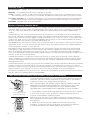
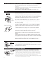
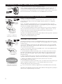
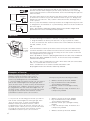
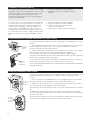
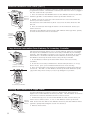
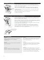
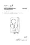
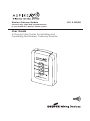
Wireless Gateway Module
Connects Key Chain and Keypad Remotes
to your ASPIRE RF™ Wireless Control System
User Guide
A Step-by-Step Guide for Installing and
Operating the Wireless Gateway Module
CAT. #: RFBGD
Thank you for purchasing the RFBGD ASPIRE RF Wireless Gateway Module. ASPIRE
RF products by Cooper WIring Devices allow you to control your home by remote
control. You can create a complete Home Control and Access Network by
combining your Wireless Gateway Module with other ASPIRE RF products. Indoor
and outdoor lighting, security systems, garage door openers, and thermostats are
just a few of the items you can easily control with additional Z-wave™ products.
Your new Wireless Gateway Module is compatible with the complete range of
Z-Wave™ enabled ASPIRE RF products. Furthermore, other Z-Wave™ enabled
modules regardless of brand will also work with your Wireless Gateway Module.
Please consult with your module supplier for more details.
Home Control Basics
ASPIRE RF products will allow you to easily control multiple devices in a home
with the push of a button in what is known as a “scene”. Turning on all of the
lights as you come home is an example of a scene. Dimming lights and closing
your curtains to watch TV, it’s also a scene.
Visit www.cooperwiringdevices.com/ASPIRERF to get ideas on how to create
scenes with your Wireless Gateway Module and other Z-Wave™ enabled ASPIRE
RF products.
Table of Contents
Package Contents................................................1
Glossary/Basics ................................................2 - 3
Set-up ................................................................4 - 6
Placement/Operation ....................................7 - 8
Advanced Features ......................................9 - 13
Troubleshooting ............................................14 -16
Regulatory Compliance ....................................18
Look for the Quick Start
symbol for basic instructions.
Package Contents
Us
er
Gu
ide
User
Guide
RFBGD
Gateway Module
Glossary
Copy – See Replicate.
Delete – Erase a transmitter, a Z-Wave™ device or scene information from Controller.
Also known as Exclude.
Device – Any item that is connected to a module (for example, lamps).
Exclude – Remove a module, transmitter, or scene from the controller.
Include – Add a module to the controller.
Module – Any ASPIRE RF or Z-Wave™ product that is controlled with a ASPIRE RF or
Z-Wave™ remote controller. A module can be part of more than one scene.
Network – A collection of Z-Wave™ devices controlled by primary and secondary controllers
operating on the same system. A network has its own unique identification code for security.
Operator – Garage door opener or garage door operator.
2
Primary Controller – The first controller used to set up modules in a network.
NOTE: Only the Primary Controller can be used to include or delete modules from a network. It is
recommended that you mark the primary controller in the network for ease in modifying the network.
Glossary (con’t.)
Remote Control -- Garage door opener transmitter (also see Transmitter).
Replicate – Copy information from one controller to another.
Scene – A scene is a series of Z-Wave™ devices programmed to activate to a specific level (on, off or
dim) with the push of a button on a controller. The Wireless Gateway Module can control 3 scenes.
Secondary Controller – A controller containing a copy of the network information that is created FROM
the primary controller. Secondary controllers cannot include or delete modules to the network.
Transmitter – Garage Door Opener transmitter.
Wireless Gateway Module Basics
The Wireless Gateway Module, by acting as a “bridge” between standard remote controls (in-vehicle
mounted, keypad or key chain) and your garage door opener, allows you to open/close your garage
door and activate a multitude of Z-Wave™ enabled modules from your car using a single remote
control.
Additionally you can activate Z-Wave™ scenes and open/close your garage door from outside your
house with a PIN keypad (wireless keyless entry). The Wireless Gateway Module will accept a different
PIN for each scene you want to trigger. Placing a PIN keypad on a deck or patio is a convenient way to
control your deck, outdoor and landscape lighting. Simply create a scene with the Wireless Gateway
Module and then activate the scene with the PIN keypad.
The ASPIRE RF keychain remote control can be carried or worn as a pendant to activate scenes inside or
outside the home. In cases where more than three scenes are required, simply add additional Wireless
Gateway Module modules to your network.
The Wireless Gateway Module communicates with your remote controls and Z-Wave™ devices using
radio signals. Large metal objects, house wiring, walls, furniture, refrigerators, microwaves and similar
items, may interfere and reduce the range of your unit. To maximize the range from the transmitter in
your car to the Wireless Gateway Module, plug the unit into an outlet with the shortest line of sight to your
vehicle, as you approach your home.
A Z-Wave™ network is a collection of Z-Wave™ devices in a mesh type of network. Each Z-Wave™
device, regardless of manufacturer, communicates with all the other modules within its range to route
and repeat the signals from one device to the next, thus creating a highly robust network transmission
throughout the home.
A Z-Wave™ network can have only one primary controller. The primary controller establishes the network
security to ensure your network will not operate your neighbor’s network and vice-versa. It is a good
practice to label and protect your primary controller since it is the only Z-Wave™ controller that can add
more modules to your network. It is easy to add secondary controllers as your network grows.
For more tips and great ideas on how to use and expand your Wireless Gateway Module please visit our
website, www.cooperwiringdevices.com/ASPIRERF.
Copy Network Information From Primary Controller To Gateway
Use the following procedure to copy network information from a Primary
Controller. This procedure is used when you are setting up the Wireless
Gateway Module to an existing Z-Wave™ network.
LED’s
Scene 1
Copy
Secondary Controller
(Wireless Gateway)
Note: This procedure can also be used to make the Wireless Gateway
Module assume the primary controller role. Please refer to your other
controller’s instructions for information on how to transfer Primary
Controller Status (via controller shift if supported) to a new controller.
1. Place Wireless Gateway Module within 6 feet of the primary controller.
2. Press and Hold the COPY and Scene 1 button simultaneously for 3
seconds on the Wireless Gateway Module.
After 3 seconds, the LED’s on the Wireless Gateway Module will turn on.
Immediately release the COPY button. The Wireless Gateway Module will
flash all LED’s.
OK
1
2
3
4
5
3
6
7
8
9
10
Primary Controller
3. Within 20 seconds, start the “SEND” function from the primary
controller. Consult the owner’s manual for your primary controller for
specific information on the “SEND” (Replicate) command.
Copy Network Information From Primary Controller To Gateway (con’t.)
The LED’s on the Wireless Gateway Module will continue to flash during
the COPY (replication) process. Once the LED’s turn off COPY is
complete.
The Wireless Gateway Module is now a secondary Controller (or primary
controller if controller shift is requested.)
Note: The process outlined above copies the network and scene
information to your Wireless Gateway Module.
Set-Up
LED’s
Use this procedure to add a Z-Wave™ device to a Wireless Gateway
Module scene button.
If you have an existing Z-Wave™ network then you must first copy the
network information from the existing primary controller to the Wireless
Gateway Module. First, follow the step titled “Copy Network Information
from Primary Controller to Gateway” to copy the existing network
information, then follow the procedure below.
Choose 1
SCENE
Button
Press and release the PROGRAM
button on the module
Tip: Scenes can be programmed to turn all modules on, off, dim or a
combination of on, off and dim.
NOTE: Perform this procedure while the Wireless Gateway Module is
battery powered only. Do not plug the Wireless Gateway Module into
AC power to program.
1. On the Wireless Gateway Module, Press and Hold the Scene button
you wish to program, (either Scene 1, 2 or 3.) The LED on the Wireless
Gateway Module will turn on immediately, then turn off, then turn on
again.
2. While holding the Scene button, Press and release the OPERATE
button on the Z-Wave™ device you wish to add to a scene.
The LED on the Wireless Gateway Module will flash three (3) times quickly
to indicate the programming is successful. Do not release the Scene
button until you see the LED’s flash (30 second max wait.)
Blue LED
on module
While holding the Scene button, Press the OPERATE button on the ZWave™ device to set the dim level or the ON/OFF state for relay type
devices.
3. Release the Scene button on the Wireless Gateway Module, the LED
on the Wireless Gateway will flash 3 times again to indicate programming
is complete.
Note: You may add multiple devices to each scene button on the
Wireless Gateway Module. Make sure Garage Door Opener has been
properly installed in accordance with unit’s installation instructions.
Manually Activating A Scene
Use the following procedure to activate a programmed scene using the
buttons on the Wireless Gateway Module.
Choose a
SCENE button
1. Momentarily Press and release the desired Scene button (1,2 or 3) on
the Wireless Gateway Module.
Programming To A Remote Control Transmitter
Use the following procedure to teach a hand held remote control
transmitter button to a scene button. This procedure is also used to
reassign a remote control transmitter button to a different scene button.
LED’s
Choose
a SCENE
Button
4
1. Press and Hold the scene button you wish to program, either Scene 1,
2 or 3, until the LED turns off, then immediately release the scene button.
2. Press and hold the desired remote control transmitter button.
The LED on the Wireless Gateway Module will flash three (3) times quickly
to indicate the programming is successful.
Programming To A Remote Control Transmitter (con’t.)
3. Release the remote control transmitter button.
Remote
Control
Transmitter
Buttons
Note: During set-up the Wireless Gateway Module will stay active for 10
seconds after programming to allow for testing the scene. After 10
seconds you must either plug the unit into an AC outlet or push one of the
three scene buttons to reactivate it for an additional 10 seconds.
Programming To In-Vehicle Mounted Remote Control Transmitter
Car2U™ In-vehicle transmitters:
LED’s
Choose
a SCENE
Button
Use this procedure to teach Car2U™ button 3 to a scene button. This
procedure can also be used to reassign Car2U™ buttons to a different
scene button.
Note: To Program Car2U™ buttons 1 or 2 to a scene button, see your
vehicle owner’s manual for instructions on programming with rolling code
receivers to change Car2U™ buttons 1 or 2.
1. Do not plug the Wireless Gateway Module into AC power to program.
Choose button 3
on your Car2U™
transmitter
Car2U™ is a registered
trademark of Lear Corp.
Press and Hold scene button you wish to program, either Scene 1, 2 or 3,
until the LED turns off, then immediately release the scene button.
2. Press and hold Car2U™ button 3.
The LED on the Wireless Gateway Module will flash three (3) times quickly to
indicate the programming is successful.
3. Release the transmitter button.
HomeLink® in-vehicle transmitters:
LED’s
Choose
a SCENE
Button
Use this procedure to teach a HomeLink® button to a scene button. This
procedure can also be used to reassign a HomeLink® button to a different
scene button.
1. Place the Wireless Gateway Module within 3 inches of the HomeLink®
transceiver. The Wireless Gateway Module must NOT be plugged into an
AC outlet for this operation.
2. Press and hold the desired HomeLink® button. The HomeLink® LED will
either flash slowly or light on solid.
Choose button 3
on your Car2U™
transmitter
3. On the Wireless Gateway Module, press and hold the Scene 1 button.
The LED on the Wireless Gateway Module will turn on immediately, then
turn off , then turn on again. This is normal. Keep holding both buttons
simultaneously.
4. Keep holding both buttons until the HomeLink® transceiver LED flashes
rapidly or turns off completely. (This process may take up to 60 seconds.)
5. Release the Wireless Gateway Module Scene button and the
HomeLink® transceiver button.
The Homelink logo and
trademark are property
of Johnson Controls, Inc.
5
6. On the Wireless Gateway Module, press and hold the Scene button you
wish to program; either Scene 1, 2 or 3 until the LED turns off, then
immediately release the Scene button.
7. Press and hold the desired programmed HomeLink® button from Step
2.
The LED on the Wireless Gateway Module will flash three(3) times quickly to
indicate the programming is successful.
Placement Of Gateway
Approach
Direction
Approach
Direction
Locate the Wireless Gateway Module in your home in a convenient
electrical outlet which will give you the best performance for receiving
your in-vehicle remote control transmitter and for transmitting the signal to
other modules.
For many users the best location is in the front corner of the home closest
to their most common approach direction which may be a dining room,
living room or bedroom. The position is indicated in the drawings with a
“Star” symbol.
Do not place the Wireless Gateway Module near large metal objects such
as refrigerators and freezers or a permanently parked car that could block
the radio signal.
Note: The Wireless Gateway Module antenna should be straight and
positioned in the most vertical position possible.
Operation
Use the following procedure to activate a programmed scene.
1. Plug the Wireless Gateway Module into an appropriate AC outlet.
2. Press and release the desired scene button on the Wireless Gateway
Module, either 1, 2 or 3.
LED’s
Choose
a SCENE
button
OR
Activate Wireless Gateway Module scenes from your hand held remote
control transmitter or in-vehicle mounted remote control transmitter by
pressing the transmitter button that corresponds to the scene to which it
was programmed. (See page 5.)
Note: By default, scene 3 is pre-programmed to ALL OFF unless Z-Wave™
devices have been added to Scene 3, in which case only the added
modules will activate.
Tip: Scenes can be programmed to turn all modules ON, turn all modules
OFF, or a combination of ON and OFF.
Note: A maximum of 12 remote control transmitters can
be programmed to the Wireless Gateway Module.
Examples of Scenes
The following examples describe how your
Wireless Gateway Module can be used.
For more ideas, please visit our website at:
www.cooperwiringdevices.com/ASPIRERF.
1. Approaching your home in your car, you wish to
turn on the outside lights near the garage, front
door and rear door, as well as lamps in the kitchen
and family room. Wireless Gateway Scene 1 can
be programmed to turn all of these lights ON. To
operate Scene 1 from your car, you will also need
to program one button of the remote control
transmitter located in your car to Scene 1.
6
2. In your car and leaving your home you wish to
turn off the outside lights near the garage, front
door and rear door, as well as interior lights.
Wireless Gateway Module Scene 2 can be
programmed to turn all of these devices OFF. To
operate Scene 2 from your car, you will also need
to program one button of the remote control
transmitter located in your car to Scene 2.
Examples require the following modules:
1 - Wireless Gateway Module, RFBGD
1 - Key chain Remote Control, RFKGT
(or in-vehicle transmitter)
3 - Dimmer Switch for each light switch),
RF9501
2 - Lamp Module (for lamp in kitchen and
family room), RFLDM
1 - Wireless Gateway Module, RFBGD
1 - Key chain Remote Control, RFKGT
(or in-vehicle transmitter)
3 - Dimmer Switch (for each light switch),
RF9501
2 - Lamp Module (for lamp in kitchen and
family room), RFLDM
1 - Wireless Gateway Module, RFBGD
Examples of Scenes (con’t.)
3. Noises outside your home awaken you during
the night. Scene 3 is programmed to turn on only
the outside lights. You can turn on Scene 3 with
your Key chain Remote Control from your
bedroom to illuminate the area and scaring off
any potential intruders.
1 - Key chain Remote Control, RFKGT
3 - Dimmer Switch (for each light switch),
RF9534
4. Lights out! You have tucked your 2 children in
bed and one has your permission to read for 15
minutes while the other has your permission to
watch TV for 15 minutes. After 15 minutes you
want to turn off their lights and TV. Scene 2 is
programmed to their bedroom lights, lamps and
to a TV in the child’s room. Using your Key chain
Remote Control you can turn their lights and TV
off.
1 - Wireless Gateway Module, RFBGD
1 - Key chain Remote Control, RFKGT
2 - Lamp Module (for lamps in each
child’s room), RFLDM
1 - Appliance Module (for the TV), RFAPM
Programming PIN keypad Transmitters (Keylerss Entry)
Use the following procedure to teach a PIN keypad transmitter to a scene
button.
LED’s
Choose
a SCENE
Button
2
6
5
4
9
8
7
Re
2. Turn the PIN Keypad transmitter on, if required, and type in your desired
PIN Code (Be sure you press the required number of digits for
your PIN keypad device, for example the RFWGT requires 5 digits.)
The LED on the Wireless Gateway Module will flash three (3) times quickly to
indicate the programming is successful.
3
1
1. On the Wireless Gateway Module, press and hold the scene button you
wish to program, either scene 1, 2 or 3, until the LED turns off, then
immediately release the scene button.
t
se
0
PIN Code
Keypad
Transmitter
To Operate the scene from the PIN keypad transmitter, turn the device on
and type in the PIN code for the scene you wish to activate.
Note: One PIN Keypad transmitter can operate multiple Wireless Gateway
Module modules.
Remove Transmitter From Scene
Use this procedure to remove a hand-held remote control transmitter or invehicle mounted transmitter from a Wireless Gateway Module scene
button.
LED’s
Scene 1
Scene 2
Scene 3
1. Press and release the DELETE button on the Wireless Gateway Module.
All three (3) LED’s on the Wireless Gateway Module will turn on.
2. Within five (5) seconds, press and release the scene button you wish to
disconnect from on the Wireless Gateway Module.
The selected scene LED will stay lit for 5 seconds and the other two will turn
off.
Delete
Remote
Control
Transmitter
Buttons
7
3. Within five (5) seconds, press the in-vehicle transmitter or hand-held
remote control transmitter button you wish to disconnect from the Wireless
Gateway Module.
The LED for the selected scene on the Wireless Gateway Module will flash
three (3) times quickly to indicate a successful disconnect.
REMOVE Z-Wave™ device FROM SCENE
Remove Transmitter From Scene (con’t.)
Use the following procedure to remove a single Z-Wave™ device from a
programmed scene. The Wireless Gateway Module must not be plugged
into AC outlet for this operation.
LED’s
1. Press and release the DELETE button on the Wireless Gateway Module.
Scene 1 All three (3) LED’s on the Wireless Gateway Module will turn on.
Scene 2
2. Within 5 seconds, press the scene button that is associated with the
Scene 3
device you want to remove.
The selected scene LED will stay lit for 5 seconds and the other two will
turn off.
3. Press and release the Program button on the Z-Wave™ device you
wish to remove.
Delete
The LED on the Wireless Gateway Module will flash three (3) times quickly
to indicate the removal was successful.
Remote
Control
Transmitter
Buttons
Copy Network Information From Gateway To Secondary Controller
LED’s
Scene 1
Z-Wave™ technology allows you to create multiple duplicate controllers.
The duplicate controllers become secondary controllers in your existing
network. The following procedure is used to send all network and scene
information to another Controller from the Wireless Gateway Module.
The Wireless Gateway Module must be the primary controller.
1. Place Wireless Gateway Module within 6 feet of the secondary
controller.
Copy
Primary Controller
(Wireless Gateway)
OK
1
2
3
4
5
2. Place the secondary controller into “Receive Replication” or “Copy
From” mode. (See your controller instructions for more details.)
3. Press and hold the COPY button on the Wireless Gateway Module for
3 seconds . The LED’s on the Wireless Gateway Module will flash rapidly
(approximately 1 flash every 1/2 second) during the operation.
6
7
8
9
10
Secondary Controller
Deleting The Content Of A Single Scene
Use the following procedure to remove all Z-Wave™ devices from a
single scene on the Wireless Gateway Module. This will delete all devices
and remote control transmitters from the chosen scene.
LED’s
1. Simultaneously press and hold the DELETE and the scene button you
wish to reset, either scene 1, 2 or 3 on the Wireless Gateway Module.
Choose
a SCENE After 10 seconds the LED on the Wireless Gateway Module will flash three
Button (3) times quickly indicating the scene was cleared.
2. Release the buttons.
8
Press and
Hold Delete
Resetting The Gateway
LED’s
Use the following procedure to factory reset the Wireless Gateway
Module. This procedure will destroy a network if the Wireless Gateway
Module is the primary controller.
Note: When resetting a Wireless Gateway Module that is a primary
controller, each device within the network must be individually reset.
Press all
SCENE 1. Simultaneously press and hold the Scene 1, 2 and 3 buttons on the
Buttons Wireless Gateway.
After 3 seconds the LED’s on the Wireless Gateway Module will flash
quickly indicating the memory was cleared.
2. Release the buttons.
Remove A Z-wave™ Device From The Network
Use the following procedure to permanently remove a single Z-Wave™
device from the Network. The Wireless Gateway Module must be the
primary controller for the network.
LED’s
Note: Use this feature only if you plan to permanently remove a device
from the network. Make sure you delete the device from all scenes in all
secondary controllers BEFORE using this procedure.
1. Press and HOLD the DELETE button on the Wireless Gateway Module
until all 3 LED’s turn on then release.
Press and
Hold Delete
2. Press and Release the INSTALL button on the device you wish to
remove. The LED’s on the Wireless Gateway Module and Z-Wave™
device will flash to indicate a successful operation. This step must be
done within 5 seconds of completing step 1.
Press and release
the INSTALL button
on the module
Green LED
on module
Troubleshooting
Problem:
Wireless Gateway Module LED’s remain lit for a
long period of time when deleting or
programming.
Problem:
Devices can not be removed from the Wireless
Gateway Module.
Problem:
How do I determine if my Wireless Gateway
Module is a primary or secondary controller?
9
Solution:
Momentarily plug the Wireless Gateway Module
into an electrical outlet to reset the device to
normal operating mode.
Solution:
The Wireless Gateway Module is a secondary
controller in the network, only Primary controllers
can be used to add or delete devices to a
network.
Solution:
Press and hold the DELETE button for 3 seconds,
if all 3 LED’s turn on the Gateway is a primary
controller, if the LED’s do not turn on, the Gateway
is a secondary controller. Do not manually
operate any Z-Wave™ devices during this test.
Troubleshooting
Problem:
When activating a Scene, the devices do not turn
on quickly and/or behave erratically.
Problem:
No Scenes activate when I use a Wireless Key
Chain transmitter to activate scenes, however
pressing scene buttons on the Wireless Gateway
Module work fine.
Problem:
The Wireless Gateway Module will not program to
a Z-Wave™ enabled device.
Solution A:
This is a common when there is a burned out
bulb in one or more devices. Replace the bulb.
Solution B:
If the primary controller was reset and all of the
devices and secondary controllers in the network
were not reset at the same time, then the newly
created network could exhibit this behavior.
The solution is to reset the primary controller,
all secondary controllers and all devices in the
network and then set up a new network.
Solution:
The Wireless Gateway Module must be plugged
into an AC outlet for power. Battery power is for
programming purposes only and has an
automatic time out feature.
Solution A:
The Wireless Gateway Module must be within 6
feet of any Z-Wave™ device during programming.
Solution B:
Be certain you are following the correct
programming approach. Programming Z-Wave™
devices requires that you Press and Hold the
scene button you wish to program on the Wireless
Gateway Module until the LED turns on, off and
then on again, then Press and Release the
Z-Wave™ device install button on the device
you want to associate with a scene. Followed
by releasing the Wireless Gateway Module
scene button.
Transmitters (such as Car2U™) require that you
Press and Hold the Scene button on the Wireless
Gateway Module module until the LED turns on,
then off, then release the Scene button, followed
by a Press and Release of the transmitter button
you wish to program.
Solution C:
If your device is part of an existing network you
must first copy the scene information from your
primary controller to the Wireless Gateway
Module. See “Copy Scenes from Primary
Controller to Gateway”, pages 7-8.
Solution D:
If your device previously belonged to another
network or you are replacing a lost or broken
primary controller then you must first delete the
device from the old network prior to adding it
to the new primary controller. See “Remove a
Z-Wave™ device From the Network”, page 9.
10
Troubleshooting
Problem:
A previously programmed remote control
transmitter no longer works.
Solution:
The Wireless Gateway Module holds a maximum
of 12 remote control transmitters, after which the
last one is replaced.
Problem:
I activated a scene but wish to abort the
execution of that scene before it is complete.
Solution:
Using a remote control transmitter such as
the Car2U™ and HomeLink®, by pressing any
previously programmed scene other than the
one you just activated, you will abort the current
scene.
Problem:
The range of the remote control transmitter I use
to activate the Wireless Gateway Module is
reduced.
Solution A:
Your remote control transmitter may need fresh
batteries, replace if necessary.
Solution B:
Check to be sure the Wireless Gateway Module
antenna is in the most vertical position.
Solution C:
Check the area around the Wireless Gateway
Module for any large metal objects which could
be interfering with the antenna reception.
Problem:
Devices take a long time to respond to a
command
Problem:
The Wireless Gateway Module works fine when
plugged into an AC outlet but when used in hand
held mode nothing works.
OR
The Wireless Gateway Module behaves erratically
and/or appears to lock up when creating scenes
or removing devices from scenes or from the
network.
Solution:
Check that all Z-Wave™ devices are on and
working, the Wireless Gateway Module may be
searching for a device that may have been
disconnected, moved, or has failed. Check for
burned out light bulbs in lamps controlled by ZWave™ devices and replace if necessary.
Solution:
Wireless Gateway Module battery needs to be
replaced. Open unit with a small philips head
screwdriver and replace the 9V battery, then
reassemble the Wireless Gateway Module.
WARNING: DO NOT PLUG THE WIRELESS GATEWAY
MODULE INTO AC POWER WHEN THE COVER IS
REMOVED.
Compliance
Covered by one or more of the following Wayne Dalton Patents D413,055; D413,579; D413,867; D421,031;
D472,568; D472,910; D473,573; D473,574; D505,393; 5,929,580; 5,931,212; 6,078,249; 6,161,438; 6,145,570; 6,164,014;
6,325,134; 6,326,751; 6,326,754; 6,401,792; 6,561,255; 6,561,256; 6,568,454; 6,588,156; 6,605,910; 6,667,591;
6,739,372; 6,845,804; 6,851,465; 6,873,127; 6,880,609; 6,903,650. Other US and Foreign Patents pending.
Z-Wave™ is a trademark of Zensys Corp.
FCC and ICC Statement
FCC Regulatory Information:
NOTE: This equipment has been tested and found to comply with the limits for a Class B digital device, pursuant
to Part 15 of the FCC Rules. These limits are designed to provide reasonable protection against harmful
interference in a residential installation. This equipment generates, uses, and can radiate radio frequency
energy and, if not installed and used in accordance with the instruction, may cause harmful interference
to radio communications. However, there is no guarantee that interference will not occur in a particular
installation. If this equipment does cause harmful interference to radio or television reception, which can be
determined by turning the equipment off and on, the user is encouraged to try and correct the interference
by one or more of the following measures:
a) reorient or relocate the receiving antenna,
b) increase the separation between the equipment and receiver,
c) connect the equipment into an outlet on a circuit different from that to which the receiver is
connected.
Consult the dealer or an experienced radio/TV technician for help.
IC Regulatory Information:
This Class B digital apparatus meets all requirements of the Canadian Interference Causing Equipment
Regulations. Operation is subject to the following two conditions: (1) this device may not cause harmful
interference, and (2) this device must accept any interference received, including interference that may
cause undesired operation of the device.
WARNING: Changes or modifications to this receiver not expressly approved by Cooper Wiring Devices could
void the user’s authority to operate this equipment.
Warranty
YOUR COOPER WIRING DEVICES ASSEMBLED PRODUCT ONE YEAR LIMITED WARRANTY
For a period of 1 year from the date of purchase, Cooper Wiring Devices will replace or repair the Wireless
Gateway Module provided that it has not been subject to abuse, improper installation or improper use, and
is returned prepaid to Cooper Wiring Devices Quality Control Department at 203 Cooper Circle, Peachtree
City, GA 30269. If the product has been discontinued, replacement will be made with the nearest available
equivalent model. This warranty does not cover consumables (such as fuses). Proof of purchase in the form
of a bill of sale or receipted invoice that shows that the item is within the applicable warranty period must be
presented to obtain the repair or replacement provided by the warranty. Repair or replacement as provided
under this warranty is the exclusive remedy of the customer. Cooper Wiring Devices shall not be liable for any
incidental or consequential damages for breach of any express or implied warranty on any of its products.
Except to the extent limited or prohibited by applicable law, any implied warranty of merchantability or fitness
for a particular purpose on this product is limited in duration to the duration of this warranty. Some states do
not allow the exclusion or limitation of incidental or consequential damages, or allow limitations on how long
an implied warranty lasts, so the above limitations may not apply to you. This warranty gives you specific legal
rights and you may also have other rights which vary from state to state.
IN U.S.A.:
Cooper Wiring Devices
203 Cooper Circle
Peachtree City, GA 30269
866-853-4293
Made in China
IN CANADA:
Cooper Wiring Devices
5925 McLaughlin Road,
Mississauga, Ontario L5R 1B8
800-267-1042
Fabrique en Chine
www.cooperwiringdevices.com/AspireRF
Importado por
(si se vende en México):
Industrias Royer, S.A. de C.V.
Tres Anegas #404
Col. Nueva Industrial Vallejo
C.P. 07700, México D.F.
01-5747-4519
Hecho en China
RFBGD1-PTA (REV A.)