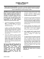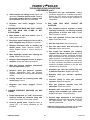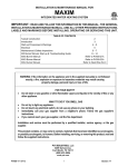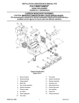
1
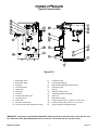
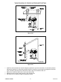
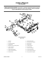
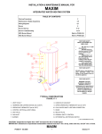
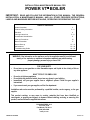
INSTALLATION & MAINTENANCE MANUAL FOR
POWER VT® BOILER
IMPORTANT: READ AND FOLLOW THE INFORMATION IN THIS MANUAL, THE GENERAL
INSTALLATION & MAINTENANCE MANUAL, AND ALL OTHER PROVIDED INSTRUCTIONS,
LABELS AND MARKINGS BEFORE INSTALLING, OPERATING OR SERVICING THIS UNIT.
TABLE OF CONTENTS
Heater Illustration
2
Product Safety Information
3–4
Electrical
4
Venting Instructions
5–8
Condensate Neutralization
9
Start-up Procedures
10
Burner Illustration
11
Burner Start-up
12 – 14
Maintenance
15 – 18
Troubleshooting Guide
19 – 20
WARNING: If the information on the appliance and in the supplied manual(s) is not followed
exactly, a fire, explosion or exposure to hazardous materials may result causing
property damage, personal injury or loss of life.
•
•
•
•
•
FOR YOUR SAFETY
Do not store or use gasoline or other flammable vapors and liquids in the vicinity of this or
any other appliance.
WHAT TO DO IF YOU SMELL GAS
Do not try to light any appliance.
Do not touch any electrical switch; do not use any phone in your building.
Immediately call your gas supplier from a neighbor's phone. Follow the gas supplier's
instructions.
If you cannot reach your gas supplier, call the fire department.
Installation and service must be performed by a qualified installer, service agency, or the gas
supplier.
This product contains, or may come to contain, materials that have been identified as
carcinogenic, or possibly carcinogenic, to humans. Before installing, servicing, or removing this
product, read and follow the supplied instructions.
PVI INDUSTRIES, LLC
P.O. Box 7124
Fort Worth, TX 76111
(800) 433-5654
www.pvi.com
PV500-23 04-2005
Section 23
POWER VT® BOILER
Typical Construction
Figure 23-1
1. Boiler water return
13.
Handhole access
2. Boiler water supply
14.
Float LWCO (optional)
3. Blowdown
15.
Manual reset temperature limiting device
4. Condensate drain
16.
Operating control
5. I-beam skid
17.
Drip leg
6. Flue outlet
18.
Electronic LWCO control
7. Gas inlet
19.
Temperature &pressure gauges
8. Induced draft blower motor
20.
Alarm bell
21.
Differential air switch
22.
Passive FGR duct (factory installed for Low NOx units)
9. Circulating pump
10. Safety valve
11. Electronic LWCO probe
23.
Passive FGR duct (field installed for Low NOx units)
12. Control enclosure with switch(es) & fuse(s)
24.
Second stage thermostat (28 hp only)
IMPORTANT: Clearance to unprotected combustible material must be 8" minimum at top, sides and rear, and
24" minimum in front. Recommended access for service is 18" at sides and rear and 24" in front.
PV500-23 04-2005
2
Section 23
POWER VT® BOILER
PRODUCT SAFETY INFORMATION
REFRACTORY CERAMIC FIBER PRODUCT
WITH CRYSTALLINE SILICA
WARNING: This product contains crystalline silica which has been identified by the International
Agency for Research on Cancer (IARC) as carcinogenic to humans. This product also contains
refractory ceramic fibers which have been identified by the IARC as possibly carcinogenic to humans.
Avoid breathing fiber particulates and dust.
RISKS:
• Airborne fibrous insulation is a possible cancer hazard by inhalation.
• Airborne crystalline silica may cause silicosis (lung disease) by inhalation.
• May cause temporary irritation to eyes, skin, and respiratory tract.
PRECAUTIONARY MEASURES:
• Minimize airborne fibers with engineering controls.
• Use NIOSH/MSHA approved respirators as required (see MSDS).
• Wear long sleeved, loose-fitting clothing, eye protection, and gloves.
FIRST AID MEASURES:
Eyes:
Flush with water.
Skin:
Wash with soap and warm water.
Ingestion: Do not induce vomiting. Get medical attention if gastrointestinal symptoms develop.
Inhalation: Remove to fresh clean air.
If any of the above irritations persists, seek medical attention.
WARNING! If you are unfamiliar with the safe handling of Refractory Ceramic Fiber
products, or if you wish additional information prior to beginning any disassembly of
the boiler that might expose refractory ceramic fiber materials, contact: Unifrax
Corporation, 2351 Whirlpool Street, Niagara Falls, NY 14305-2413, 1-800-322-2293.
PV500-23 04-2005
3
Section 23
POWER VT® BOILER
WARNING
This boiler is equipped with an
adjustable thermostat to control water
temperature. Hot water temperatures
required for automatic dishwasher and
laundry use could cause scald burns
resulting in serious personal injury
and/or death. The temperature at which
injury occurs varies with the person's
age and time of exposure. The slower
response time of disabled persons
increases the hazards to them. Never
allow small children to use a hot water
tap or to draw their own bath water.
Never leave a child unattended in a
bathtub or shower.
Since the thermostat temperature
setting could be set too high, adjust the
thermostat temperature setting to 125°F
or lower. Lower settings help reduce risk
of scald injury. Remember, no boiler
system will provide exact temperature at
all times. Allow a few days of operation
at this setting to determine the correct
temperature setting consistent with your
needs and remember, "Hotter water
increases the risk of scald injury." Also,
the boiler should be located in an area
where the general public does not have
access to set temperatures.
ELECTRICAL
1. Wiring to the unit should conform to the
National Electrical Code or the code legally
authorized in your locality. A fused disconnect
switch should be used for the boiler. When
required, PVI boilers are equipped with stepdown transformers located within the NEMA
enclosure. This allows for an effective single
point electrical connection to the boiler.
3. When remote on/off, air proving interlock, flow
switch or lead-lag enable operation is used,
remove jumper from FS and R2 and wire in
series.
4. A proper earth ground for this unit must be
provided. PVI recommends a single conductor
ground wire be pulled from the distribution
panel to the sub panel (or some similar type).
2. Be certain that high and low voltages are
connected to the correct points.
NOTE: Use only copper wiring of proper sizing for incoming service. Damage resulting from use
of aluminum wiring will be excluded from coverage under the warranty of this unit.
PV500-23 04-2005
4
Section 23
POWER VT® BOILER
VENTING INSTRUCTIONS
VENT SIZING
C. Multiply the number of 45° elbows used in
vent system by the equivalent length of
straight pipe specified in Table 23-1.
Venting to and from this unit should conform to
the National Fuel Gas Code, Latest Edition. The
POWER VT® boiler is designed for operation with
the 4", 5” or 6” positive pressure vent systems
constructed of AL29-4C stainless steel.
D. Add (A), (B) and (C) together to obtain the
total feet of venting. This length must not
exceed the maximum vent length identified in
Table 23-1.
WARNING: Do not use Type B vent or
plastic vent of any type. These materials
are not temperature or pressure rated
for this appliance and could result in
fire, injury, or death.
Example: A 4" venting system of 25 ft. of straight
pipe and two 90° elbows.
• Total straight pipe = 20 feet.
• Number of elbows (2) x 14 = 28 equivalent
feet of straight pipe.
• 20 feet plus 28 feet = 48 equivalent feet of
venting.
This is an acceptable vent system.
VENT SYSTEM DESIGN
The POWER VT® boiler can be vented either
vertically, through a ceiling or roof, or horizontally
through a wall. From the vent pipe at the blower
outlet, the vent can be routed in any direction
except down. Like any closed piping system, the
vent should maintain a downward slope toward
the heater of at least ¼ inch per lineal foot of
horizontal vent run to allow proper drainage of any
accumulated moisture. Despite this flexibility, the
following limitations and precautions must be
observed. (Per NFPA Z22.1-1 “Provision shall be
made to drain off and dispose of condensate from
a venting system.” A fitting, no more than 18” from
the combustion blower, should be provided in the
venting to route vent condensate away from the
blower.)
NOTE:
Consult
manufacturer for
installation details.
Horizontal Venting Through a Wall
The vent must extend one foot beyond the wall.
The vent must not exit over a public walkway or
over any other area where condensate or vapor
could be hazardous.
The vent must discharge at least three feet above
grade of the level of normal snow accumulation.
Determination of Equivalent Length
The vent must terminate at least four feet below,
four feet horizontally from, or one foot above any
building air inlet including doors and windows.
Maximum equivalent length of vent must not
exceed the length identified in Table 23-1:
Vent Pipe
4
5
6
Equivalent length
90° elbow 45° elbow
14
5
18
7
21
8
Maximum Vent Length
28 hp
All others
50
100
150
300
390
500
Vertical Venting Through a Roof
•
Table 23-1
A. Add the total length of straight pipe (in feet).
The vent must extend upwards beyond nearby
obstructions in accordance with Figures 23-2
and 23-3 (see page 7).
Venting of Multiple Units
B. Multiply the number of 90° elbows used in
vent system by the equivalent length of
straight pipe specified in Table 23-1.
PV500-23 04-2005
the
vent
system
specific design and
•
5
Multiple POWER VT® models must not be
vented into a common duct or breeching. Each
unit must be independently vented in
accordance with the instructions for either
horizontal or vertical venting included above.
Section 23
POWER VT® BOILER
VENTING INSTRUCTIONS (con't)
AIR INLET DUCT OPTION
When ducting horizontally through a wall:
(Figure 23-5, page 8)
Air inlet duct is defined as a means of ducting the
outside combustion air to the burner for the
purpose of avoiding corrosion that can be caused
by contaminants which may be contained in
indoor air and/or providing sufficient fresh air for
proper combustion. If your POWER VT® boiler
requires an air inlet duct, it can be connected
directly to the burner inlet cap with self-tapping
screws. No additional parts are necessary.
•
The duct must extend one foot beyond the wall.
•
The duct must be terminated with the UL listed
vent termination provided by PVI.
•
The duct must terminate at least three feet
above grade or the level of normal snow
accumulation.
Constructing the Air Inlet Duct
•
Maximum Equivalent Length of Duct
Use 6 inch, PVC sewer and drain pipe when
constructing the combustion air duct for all
POWER VT® boiler models. Single-wall
galvanized may be used when PVC is not
available. Care should be taken to tape all duct
joints and connections.
•
The combustion air duct should be no more
than 100 equivalent feet in length, but it may be
of different configuration. See section on vent
system
design
for
details
concerning
combustion air duct construction.
When ducting vertically through a roof:
(Figure 23-4, page 8)
•
The duct must be terminated with the UL listed
vent termination provided by PVI.
PV500-23 04-2005
6
Section 23
Typical Termination Locations for Vertical Vent Pipes
Termination of less than 10 feet
Figure 23-2
Termination of more than 10 feet
Figure 23-3
Vertical vent pipe must be terminated with the UL listed vent termination supplied by PVI.
PV500-23 04-2005
7
Section 23
Typical Locations for Vertical and Horizontal Vent Pipes
Vertical Venting
Figure 23-4
Horizontal Venting
Figure 23-5
•
•
•
•
Install flue outlet and fresh air inlet with adequate separation to prevent recirculation of combustion products.
Although the National Fuel Gas Code provides minimum clearances, sound engineering judgement should be
used, considering prevailing winds, obstructions and the type vent termination used, etc.
Either flue or remote air intake can be roof or side wall vented.
Maximum length of remote intake ducting is 100 equivalent feet.
See Table 23-1 for maximum length of combustion venting.
PV500-23 04-2005
8
Section 23
POWER VT® BOILER
CONDENSATE NEUTRALIZATION & DISPOSAL
The POWER VT® boiler can produce significant
amounts of condensate because of their high
efficiency. Condensate occurs naturally when
water vapor in combustion gases is cooled below
the dew point. Although only slightly acidic,
POWER VT® boiler condensate can be routed
through an optional neutralization system to
become pH neutral allowing for disposal into any
drain or sewer system without concern for
corrosion. A fitting should be provided in the
venting to route any vent condensate away from
the combustion blower. This can be accomplished
by installing a tee in the vent not more than 18"
from the combustion blower outlet.
PV500-23 04-2005
Crushed
limestone
fills
the
condensate
neutralization bath. Condensate slowly flows
through the limestone bed and is neutralized thus
avoiding chemical treatment or dilution using
substantial quantities of tap water. If the
condensate pH is lower than 4 when checked with
a pH meter or pH paper, consult the factory for
replacement treatment system. Condensate
drainage from the POWER VT® boiler will only
occur after a recovery run cycle. If no condensate
is drained during this time, the drainpipe should
be inspected for blockage. Should the heater not
be installed on a housekeeping pad to ensure
gravity drainage, a means of removing
condensate, such as a pump, should be supplied
in the system.
9
Section 23
POWER VT® BOILER
START-UP PROCEDURES
WARNING: START-UP SHOULD ONLY BE PERFORMED BY A QUALIFIED TECHNICIAN.
CAUTION: DO NOT RELIGHT PILOT OR START BURNER WITH COMBUSTION CHAMBER
FULL OF GAS OR OIL VAPOR, OR WITH VERY HOT COMBUSTION CHAMBER.
WARNING!
YOU MUST CONNECT THE SUPPLIED GAS TRAIN TO THE BURNER UNION. THE GAS
SUPPLY MUST THEN BE CONNECTED TO THE GAS TRAIN. DO NOT CONNECT THE
GAS SUPPLY DIRECTLY TO THIS UNION.
FAILURE TO INSTALL THE SUPPLIED GAS TRAIN TO THE BURNER UNION BEFORE
CONNECTING THE GAS SUPPLY MAY RESULT IN UNCONTROLLED GAS FLOW INTO
THE APPLIANCE AND/OR THE APPLIANCE AREA.
FAILURE TO FOLLOW THIS WARNING COULD RESULT IN FIRE OR EXPLOSION
CAUSING PROPERTY DAMAGE, PERSONAL INJURY OR DEATH.
1. The Power VT gas valve and control train (gas
train) provided with the appliance must be
directly connected to the union piped out of the
burner. After the gas train is attached to the
burner, the gas supply can be connected to the
gas shut-off valve (gas cock) at the gas train
inlet. After gas plumbing is complete, verify the
gas train is adequately supported and connect
the conduit and multipin plug into the multipin
receptacle in the gas train conduit box.
2. Carefully study the burner start-up information
included in this manual.
Fill system tank with water. Some water boilers
may be equipped with an optional air vent. If
venting through the safety valve when filling the
boiler, insure gags or fixtures are removed from
the safety valve prior to start-up. Open the safety
valve to allow air in the tank to escape.
Be sure all connections into the tank are tight, as
leaks at tank fittings will damage the insulation.
3. The manual reset thermostat is a temperature
limiting safety device set at 215°F; the operating
thermostat is set at the factory at 180°F for on-off
operation. For two-stage models, a second
operating thermostat is used to control the
second stage operation and should be set
approximately 10°F below the primary operator.
Adjustment may be made by turning the
thermostat dial to the desired temperature.
CAUTION: CONDUCT THE FOLLOWING GAS TRAIN LEAKAGE TEST BEFORE
START-UP, AT ANNUAL INTERVALS AND PRIOR TO INVESTIGATING THE CAUSE OF
ANY REPORTED OCCURENCES OF DELAYED IGNITION.
1. Using an appropriate bubble detection solution,
thoroughly coat all gas train pipe connections. If
any bubbles are detected, the leaking connection
must be tightened, recoated, and rechecked to
assure stoppage of the leak.
measured gas pressure in inches of water
column (W.C.). Measure gas pressure again after
15 minutes. If gas pressure has increased 0.5"
W.C. or more, the gas leak must be isolated to
one or more of the operating gas valves. (For
example, a solenoid actuated gas shutoff valve.)
After any leaking valve is replaced, the
reassembled gas train must be leak tested again
before start-up is attempted.
2. Attach a manometer to measure the gas
pressure at the manual gas shutoff valve located
just upstream of the gas train. Adjust gas train
inlet pressure to the specified value (e.g. 14"
W.C.), and tightly close the gas train manual
shutoff valve closest to the burner.
3. Reattach the manometer to the gas train manual
shutoff valve at the burner and record the
PV500-23 04-2005
10
Section 23
POWER VT® BOILER
GAS BURNER
CARBON MONOXIDE WARNING: An annual or seasonal combustion checkout must be
performed by a qualified service agency to ensure safe operation. Failure to maintain
proper combustion can result in injury or death.
Typical Construction
Figure 23-6
1.
Static fan
11.
Manual shutoff valves
2.
End cap
12.
Main gas pressure regulator
3.
Gas nozzle assembly
13.
Main gas valve
4.
Pressure plate
14.
Pilot gas valve
5.
Blast tube & burner housing junction
15.
Auxiliary gas valve
6.
Ignition transformer
16.
Electrode clamp
7.
Ignition electrode
17.
Fresh air vent damper
8.
Flame sensing electrode
18.
FGR union with orifice
9.
Ignition electrode boot (red)
19.
Flame electrode boot (black)
Electrode clamp
20.
Pilot gas pressure regulator
10.
PV500-23 04-2005
11
Section 23
POWER VT® BOILER
GAS BURNER START-UP
(Refer to Figure 23-6, page 11 to identify burner parts)
WARNING: START-UP SHOULD ONLY BE PERFORMED BY A QUALIFIED TECHNICIAN.
1. Remove enclosure panel cover on the boiler to
expose control circuit. A wiring diagram, included
in this packet, will show the controls used in our
circuitry.
2. Visually check that all components are intact and
no damage has occurred during transit.
3. Check all connections within the control cabinet.
A loose connection could cause intermittent
shutdowns.
4. Some burners will use direct spark ignition. They
may use a single gas pressure regulator and gas
valve or multiple valves and regulators. On a call
for heat, the motor starts, gas primary control is
energized, the air vent damper opens and after a
short delay (pre-purge), the gas valve(s) opens
and ignition should occur.
NOTE: Do not tamper with or readjust program
dipswitch settings. This will cause the control to
become inoperable. Damage resulting from
tampering will be excluded from coverage under
the warranty of this unit.
7. Connect a manometer to the manifold test port at
the shutoff valve closest to the burner. Turn off
main gas shutoff valve. Turn unit on using the
rocker switch on the side of the control enclosure
assembly. If the operating control switches are
closed, the burner blower should come on and
pre-purge begins.
8. If nothing happens, check the control to be sure it
is not in the tripped position and reset it by
pushing the flame safeguard reset button. The
burner should pre-purge at least thirty seconds.
9. When the blower motor starts, the air damper will
open and the airflow proving light on the
MEC120 should be on. This indicates a positive
airflow condition. If the air proving light is not on,
check the air-proving switch for operation. To
adjust the air-proving switch, turn the adjustment
screw counter-clockwise until the air proving light
comes on, then turn the screw one turn counterclockwise. If the gas valves open and close
intermittently during normal operation, turn screw
one half turn counter-clockwise until this
condition ceases. This procedure should be
followed with every burner.
5. Connect a test meter to the control for reading
the flame response signal.
This section is for single-stage and two-stage
firing: After purging is complete, terminal 3 on
the flame control energizes the pilot valve and
terminal 4 energizes the ignition transformer. The
pilot is then established. The VDC reading on the
meter should read a steady 6-10 VDC; 6 VDC is
the minimum flame signal for it to operate
reliably. If the pilot fails to light during the initial
period, it is probably due to air in the line. The
control will lock out and require reset.
NOTE: Some controls read the flame signal in
micro amps and some in volts DC. The M series
control has two terminals marked for reading
volts in DC.
CAUTION: Be sure the tank is filled with
water. Dry firing can destroy the boiler.
6. Check the gas pressure before start-up, using a
U-tube manometer or a 0 to 28" W.C. pressure
gauge for inlet gas pressure. (This is the
pressure measured before all components in the
gas train.) The manometer must stay connected
throughout the testing, as the inlet pressure must
be monitored during the firing of the burner.
Record static pressure; it must not exceed 14"
W.C. Pressures above this could cause damage
to the diaphragm in the gas valve or pressure
regulator.
PV500-23 04-2005
Once the flame is established, the ignition
transformer will de-energize and terminal 5 will
energize the main valve. At this point the boiler is
operating at maximum firing rate (high fire). In
order to insure the boiler is operating at the rated
input, it is necessary to check the manifold gas
pressure (measured at the pressure tap on the
gas valve closest to burner). The manifold gas
pressure should be adjusted at main gas
regulator to the factory recommended pressure
shown on tag attached to gas train. Do not screw
the adjusting nut of the regulator in beyond point
where no further increase in manifold pressure is
noted.
12
Section 23
POWER VT® BOILER
GAS BURNER START-UP (con't)
While firing, check the gas pressure at the inlet of
the gas train. The minimum supply pressure
requirement on the Power VT boiler is 4.5" W.C.
supply unless otherwise specified on the data
plate. It should be a minimum of that shown
above with the boiler running at high fire. This is
recorded as inlet flow pressure. It is important
incoming pressure does not fall below this
minimum or nuisance control lockouts could
occur.
This section is for two-stage firing only: After
adjusting the high fire manifold gas pressure, it is
now important to check the operation of the first
stage (low fire). There is a toggle switch on the
control cabinet labeled “Auto/Low Fire”. Switch
from the auto position to low fire and the main
valve will de-energize shutting off the high fire gas
supply and the air damper will close reducing the
airflow to a minimum. Once the boiler is at low fire
the manifold gas pressure can be adjusted as
described in the previous paragraph but using the
pilot gas regulator instead of the main gas
regulator. Proceed to paragraph 10 to test and
document combustion results for low fire and high
fire.
e) CO should not exceed 200 ppm. A reading
greater than 200 ppm indicates lack of air.
Reduce manifold gas pressure slightly and
take readings until CO is within proper range.
Optimum reading is no CO.
f)
g) Record CO2 and NOx if applicable. See
paragraph 11 if NOx measurement is required.
h) Insert vent temperature gauge in test opening
and read gross vent temperature; maximum
gross stack is to be 275°F. If an excessively
high gross vent temperature is recorded;
consult the factory.
11.
When the Power VT Boiler is equipped for Low
NOx operation, it may be necessary to measure
the NOx levels in the flue products for
compliance verification. The NOx concentrations
are measured in ppm (parts per million). When
documenting the measurements on the startup
report, be sure to note whether or not the
readings are corrected to a baseline O2 level. If
during the course of startup the NOx levels do
not meet your locally mandated requirements, it
may be necessary to change the FGR (flue gas
re-circulation) orifice. This orifice is contained in
the FGR union shown on page 10, Figure 23-6.
This union may contain two or more orifices.
This allows the removal of one or more of the
orifices in order to increase the flow of FGR and
thereby reduce NOx in the flue products. If the
FGR orifice is changed for any reason, the
startup procedure in paragraph 10 should be
repeated.
10. Check flue gases with an electronic flue analyzer
to make final settings of gas pressure regulator.
a) The readings need to be taken from a hole in
the vent several inches downstream of the fan
outlet connection.
b) Insert 0-6" W.C. manometer into the test
opening in the vent. Pressure in stack should
not exceed 2" W.C.
c) When water in tank is above 120°F, insert
analyzer or O2 testing in test opening; take O2
reading in percentage.
d) Increase manifold gas pressure at the main
gas pressure regulator taking O2 reading at
each adjustment of gas regulator until
optimum O2% (5-7%) is reached. If O2%
decreases, reduce the gas pressure to last
reading where the greatest reading is
achieved.
PV500-23 04-2005
If manifold pressure was changed during
startup, take a final CO and O2 reading.
12.
Check each operating and limit control to be
sure they function properly by lowering and
raising the temperature setting on each of the
controls, causing burner to cycle on and off.
NOTE: During the initial firing of the burner,
smoke that is not related to the burner will be
emitted from the heater. This is normal during
"burn in" and could possibly continue for
several hours.
13
Section 23
POWER VT® BOILER
GAS BURNER START-UP (con't)
13.
Record the following information for future use:
NOx reading
a) Manifold gas pressure
" W.C.
f)
b) Vent pressure
" W.C.
g) Vent temperature
ppm
c) O2 reading
% (5-7%)
Gross
°F.
d) CO2 reading
% (8-9%)
Less ambient
°F.
Net
°F.
e) CO reading
PV500-23 04-2005
ppm (less than 300 ppm)
14
Section 23
POWER VT® BOILER
MAINTENANCE
CARBON MONOXIDE WARNING: An annual or seasonal combustion checkout must be
performed by a qualified service agency to ensure safe operation. Failure to maintain
proper combustion can result in injury or death.
CAUTION: Be sure manual valves and
burner electrical switch are turned off
before removing any part for service or
cleaning. Do not push relay contacts in
manually; accidental opening of main
automatic valve can result. Ensure there
is no pressure on the vessel prior to
disassembly of any water carrying
component to prevent serious injury.
1.
A preventive maintenance is recommended to
assure a long, trouble-fee life of the boiler.
Refer to ASME Section VII for a
comprehensive plan for boiler operation,
maintenance and lay-up.
A table of periodic safety inspections is
attached to this manual for ease of reference
by the building service technician or licensed
equipment operator (Table 23-2, page 17).
Since boiler designs vary, only some of these
listed inspections may be appropriate for your
particular model.
2.
Proper water treatment is critical to prevent
corrosion as well as to reduce scale, both of
which will reduce the life of the boiler. Hydronic
heating systems, steam heating systems and
process steam systems all have different
treatment requirements. The makeup of the
water, just as the blowdown, will vary with each
application. Rely on the recommendation of the
water consultant.
SINCE PVI CANNOT CONTROL THE USE OF
THE BOILER, WATER CONDITIONS OR
MAINTENANCE, THE WARRANTY ON THE
BOILER
DOES
NOT
COVER
POOR
PERFORMANCE, STRUCTURAL FAILURE OR
LEAKING
DUE
TO
AN
EXCESSIVE
ACCUMULATION OF SCALE. HOWEVER,
SHOULD A FIRETUBE LEAK FOR ANY
REASON, CONSULT THE FACTORY FOR
INSTRUCTIONS.
PV500-23 04-2005
3.
Examine the venting system at least monthly
for proper connections, alignment, or the
presence of corrosion. If corrosion appears,
the boiler must not be operated until the
corroded vent section(s) is replaced.
4.
Oil the blower motor and wipe oil and dust from
the burner at regular intervals. The static fan
will collect dust from the air during operation.
Clean the screen and fan blades if necessary.
The burner should be cleaned each year.
Inspect all parts and make replacements when
necessary. Check wiring for loose connections
and burned wires.
5.
Periodic inspections and check-out of the
burner ignition system, control system and fuel
valve operation (for tight close-off) should be
made. Refer to the burner installation
instructions for inspection recommendations.
6.
Inspect operating controls to ensure they are
level, especially those containing mercury
switches. Make sure connecting tubing is not
kinked or damaged on remote bulb
thermostats.
7.
The pressure safety valve should be checked
at regular intervals by manually opening the
valve. The openings inside the valve may
become restricted by a buildup of scale and
become inoperative. If the valve does not open
and close properly, it must be replaced. Shut
down boiler, relieve internal pressure, and
replace safety valve with a like kind or one
meeting the requirements stated on the rating
decal located adjacent to the safety valve
mounting location.
CAUTION: The safety valve is a primary
safety device.
15
Section 23
POWER VT® BOILER
MAINTENANCE (con't)
8.
9.
The need to periodically check water level
controls and waterside of the pressure vessel
cannot be over emphasized. Most instances of
major boiler damage are the result of operating
with low water or the use of untreated (or
incorrectly treated) water.
Determine piping is vertically aligned after
shipment and installation and throughout the
life of the equipment. The operation of the
electronic low water cutoff may be checked in
the same manner, by bypassing the function of
the float low water cutoff.
Every boiler is equipped with an electronic low
water cutoff. This device senses continuity
between a probe located in the top of the tank
and the water to verify the presence of water. It
is important to check the operation of this
device periodically.
10. It is important to blowdown the float low water
cutoff devices when supplied. It is
recommended that a short blowdown be
conducted daily. Float low water cutoffs should
be equipped with test-n-check valves to allow
blowdown of low water cutoff without requiring
complete drainage of the boiler.
This boiler may be equipped with a float-type
low water cutoff. Since low water cutoff devices
are generally set by the original manufacturer,
no attempt should be made to adjust these
controls to alter the point of low water cutoff. If
a low water device should become erratic in
operation or if it's setting changes from
previous established levels, check for reasons
and correct; repair or replace as required.
11. A boiler used for heating or seasonal loads or
for standby service may have an extended
period of non-use. Special attention must be
given so that neither waterside nor fireside
surfaces are allowed to deteriorate from
corrosion.
There are two methods of storage – wet or dry.
Your water consultant or feedwater treating
company can recommend the better method,
depending upon circumstances in a particular
installation. Section VII of the ASME Code also
contains information relating to laying up a
boiler.
The controls operation may be checked by
stopping the water supply to the boiler while
the burner is operating at low fire. While under
constant attendance allow the water to lower at
a normal rate. If a control does not break the
circuit to stop the burner at the proper point,
then
SHUT
DOWN
THE
BURNER
IMMEDIATELY.
12. Extended shutdown of the boiler and restarting
are as follows:
1. Turn off all power and fuel supplies.
2. Enter boiler into dry storage.
3. Tag power switch(es) that fuel is off
and tank is in storage condition.
4. Remove tank from storage and turn
fuel and power switch(es) on to start.
Reset all controls and conduct startup
of the boiler as discusses previously.
Do not restart until all cross connecting piping
is checked for obstructions. Also check the
float bowl. If these are clean, repair or replace
the control. Repeat the above test to insure
proper operation prior to returning the boiler to
service.
Remove the pipe plugs from the tees and
crosses and make certain the cross connecting
piping is clean and free of obstructions.
Controls must be mounted in a plumb position
for proper performance.
PV500-23 04-2005
16
Section 23
POWER VT® BOILER
MAINTENANCE (con't)
Burner and Control Maintenance
to place each electrode and insert electrode
through hole, retaining stud end first.
13. Remove the flame safeguard control from its
base. Check the connections in control
mounting base; loose connections can cause
nuisance shutdowns.
17. Tighten electrode-mounting clamp slightly until
electrode ceramics are seated firmly and
completely in the mounting bracket without gaps
between ceramics and mounting bracket at the
bearing faces.
NOTE: Always secure gas lines and tag "Out of
Service" before servicing burner nozzle or
electrodes.
18. Measure and set electrodes according to Figure
23-7 below. After gaps and setting are
complete, fully tighten the electrode-mounting
clamp. Do not overtighten or ceramic insulation
may crack.
14. Pull the nozzle assembly to check the flame and
ignition electrodes. This is done by first
disconnecting the gas train by breaking at the
unions. Then remove the nozzle assembly with
the electrodes and pressure plate attached.
Disconnect the electrode wires. Take care not to
damage the insulation on the electrodes.
19. Replace nozzle assembly; be sure to connect
the flame and spark rod wires before installing
nozzle assembly fully into blast tube. Check
connections on the ends of the flame and spark
rod wires for good contact. Look for properly
stripped wire ends. Be sure connections are
firmly attached to the flame and ignition rod
ends. Insulating boots can give a false feeling of
proper
seating.
DO
NOT
MOVE
ELECTRODES. Be careful not to bump
electrodes. Check fan wheel for free rotation.
15. With electrodes exposed, check for the proper
settings as in Figure 23-7 below. Check for any
hairline cracks in the insulators. Should
replacement of burner electrodes be required,
certain procedures must be followed. In all
cases, removal of electrodes is accomplished
by loosening the electrode mounting clamps.
Draw electrodes out of the nozzle assembly
through the holes in the pressure plate.
20. Reinstall gas nozzle assembly.
16. Inspect electrodes for cracked ceramic or loose
retaining studs that hold the wire within the
ceramic. Select the proper pressure plate hole
PRESSURE PLATE
Set up and Tolerances
Figure 23-7
PV500-23 04-2005
17
Section 23
MAINTENANCE & SAFETY INSPECTION REPORT
DATE
BURNER
INSPECTION
COMBUSTION
ANALYSIS
TANK
INSPECTION
TANK FLUSH
& CLEANOUT
TANK FITTING
INSPECTION
VENT
INSPECTION
THERMOST
AT
INPSECTION
GAS TRAIN
LEAK TEST
Recommended
Inspection
Intervals
YEARLY
6 MONTHS
6 MONTHS
3 MONTHS
6 MONTHS
YEARLY
YEARLY
YEARLY
TABLE 23-2
PV500-23 04-2005
18
Section 23
POWER VT® BOILER
TROUBLESHOOTING SUGGESTIONS
GAS BURNER
1. BURNER FAILS TO START:
c) With flame safeguard controls that
incorporate the air flow switch in the nonrecycling circuit, ensure that when main flame
lights, the air flow switch is not so critically set
as to allow occasional momentary opening of
the air switch contacts.
a) Defective on/off switch. Replace switch.
b) Control circuit has open control contact.
Check limits, low water cutoff, and others as
applicable.
d) Occasional low supply voltage. Contact local
utility to correct. Make certain the burner control
circuit transformer (if supplied) is correct of the
voltage and power (AC) being supplied.
c) Bad fuse or switch opens on incoming
power source. Correct as required.
d) Flame safeguard control safety switch
tripped out. Reset and determine cause of
apparent flame failure.
e) Occasional low gas supply
Contact local utility to correct.
pressure.
e) Loose connections or faulty wiring. Tighten
all terminal screws and consult wiring diagram
furnished with the heater.
f)
f)
g) Excessive flue gas recirculation, causing
unreliable or unstable operation. Reduce the
orifice size in the FGR union and readjust the
gas regulators to achieve proper excess air in
combustion.
Flame safeguard control starting circuit
blocked due to flame relay being energized.
Possible defective scanner or flame rod –
replace. Possible defective amplifier – replace.
Scanner actually sighting flame due to leaking
fuel valve – correct unwanted flame cause.
Defective flame safeguard control – replace.
3. BURNER MOTOR RUNS, BUT PILOT DOES
NOT LIGHT:
g) Defective blower motor. Check for free
rotation of fan wheel. Repair or replace.
a) Gas supply to burner shut off. Make sure all
manual gas supply valves are open. Automatic
high-pressure valve at meter such as "Sentry"
type tripped shut due to high gas pressure.
Reset valve and correct cause for trip out.
h) Air proving switch is not properly adjusted.
Adjust per instructions; page 12, paragraph 9.
i)
Defective
replace.
circulation
pump.
j)
Regulator vent line(s) plugged. Remove
blockage.
2. OCCASIONAL
LOCKOUTS
APPARENT REASON:
Repair
FOR
or
b) Pilot solenoid valve not opening. Listen and
feel for valve actuation. Solenoid valve not
being powered. Check electrical circuitry.
Replace coil of entire valve if coil is burned out.
c) Defective gas pilot regulator. Replace.
NO
d) Gas pressure too high or too low at pilot
orifice (if supplied). Check orifice size in gas
pilot assembly. Replace if incorrect. Readjust
pressure as required.
a) Gas pilot ignition failure. Check to see that
ignition is instant and flame signal readings are
stable and above minimum values. Use an
incline manometer to make certain pressure is
as recommended.
e) Defective ignition transformer. Replace.
Incorrect
ignition
electrode
settings.
Readjust as required.
b) Loose or broken wires. Check all wire nut
connections and tighten all terminal screw
connections in panel and elsewhere as
appropriate.
PV500-23 04-2005
Regulator vent line(s) plugged. Remove
blockage.
f)
19
Defective component within the flame
safeguard control. Replace as required.
Section 23
POWER VT® BOILER
TROUBLESHOOTING SUGGESTIONS
GAS BURNER (con't)
c) Excessive flue gas recirculation, causing
insufficient excess air for complete combustion.
Reduce the FGR orifice size and readjust the
gas regulators to achieve proper excess air in
combustion.
g) Airflow switch not making circuit. Check out
electrically. Defective airflow switch. Replace.
Air switch negative pressure sensing tube
out of position. Reposition as necessary.
h) Regulator vent line(s) plugged. Remove
blockage.
6. GAS HIGH
ACHIEVED:
INPUT
CANNOT
BE
a) Gas Company pressure regulator or meter
operating incorrectly, not allowing required
gas pressure at burner train inlet. Contact
Gas Company to correct.
4. BURNER MOTOR RUNS AND PILOT LIGHTS,
BUT THE MAIN GAS FLAME IS NOT
ESTABLISHED:
a) Main shutoff or test cock closed. Check to
make certain fully open.
b) Gas cock upstream of train inlet not fully
open. Check and correct.
b) Pilot flame signal reading too low to pull in
flame safeguard relay. Readjust as required.
c) Gas line obstructed. Check and correct.
c) Defective automatic main or auxiliary gas
shutoff valves. Check electrical circuitry to
valves. Replace valves or correct circuitry as
required.
d) Gas train main and/or lead test cocks not
fully open. Check and correct.
e) Gas supply line between gas company
regulator and burner inlet too small. Check
supply pressure at meter, determine pressure
drop and increase line size as required, or raise
supply pressure to compensate for small line.
Do not raise pressure so high that under static
(no flow) conditions the pressure exceeds the
maximum allowable pressure to the gas train
components on the burner.
d) Main diaphragm shutoff valve opening too
slowly. Adjust bleed on valve.
e) Defective flame safeguard control or plug on
amplifier. Check and replace as required.
f)
FIRE
Main gas pressure regulator atmospheric
vent line obstructed. Correct.
f)
g) Defective main gas pressure regulator.
Replace. Misadjusted main gas pressure
regulator. Readjust to meet required operational
values.
Automatic gas valve not opening fully due
to defective operation. Replace gas valve.
g) Defective main gas pressure regulator.
Replace.
h) Polarity reversed on incoming power (S89
control only). Correct.
h) Incorrect spring in main gas pressure
regulator. Replace as required.
i)
Regulator vent line(s) plugged. Remove
blockage.
i)
Main gas pressure regulator vent line
obstructed. Check and correct.
5. CARBON MONOXIDE READINGS ON GAS
FIRING:
j)
Normally open vent valve (if supplied) not
closing when automatic gas valves open.
Replace vent valve, if not closing fully.
a) Flame impingement on "cold" heat transfer
surfaces caused by excessive firing rate.
Reduce firing rate to correct input volume.
k) Second stage thermostat is not properly
adjusted. Second stage thermostat should be
set approximately 10°F below the primary
operating thermostat.
b) Incorrect gas/air ratios. Readjust burner to
correct CO2 / O2 levels, eliminates all CO
formation.
PV500-23 04-2005
Additional troubleshooting information can be found
in the Flame Safeguard bulletin with the burner.
20
Section 23