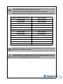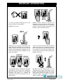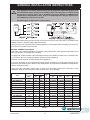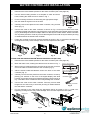
1
Operation / Installation
Manual
To Suit Water Heater Models:
INFINITY 32
REU-VR3237WG
INFINITY 26
REU-VR2626WG
INFINITY 26 Plus
REU-VRM2630WD
INFINITY 26i
REU-VR2632FFUG
INFINITY 20
REU-VR2024WG
INFINITY 16
REU-VR1620WG
INFINITY ENVIRO 32 REU-KM3237WD
INFINITY ENVIRO 26 REU-KM2635WD
V1500
REU-VR2426WB
V1200
REU-VR1620WB
HD250e
REU-VRM3237WC
HD200e
REU-VRM2632WC
HD200i
REU-VRM2632FFUC
Please see the inside front cover of this manual for additional
Rinnai continuous flow water heater models covered by this manual.
How to use and install Rinnai continuous flow water heaters
This appliance shall be installed in accordance with:
• Manufacturer’s Installation Instructions
• Current AS/NZS 3000, AS/NZS 3500 & AS 5601
• Local Regulations and Municipal Building Codes
This appliance must be installed, serviced and removed by an Authorised Person.
Some additional Rinnai continuous flow water heater models not listed on the front
cover of this manual are also covered by this manual.
NOTE
The following table lists these additional models and their equivalent.
When using this manual use the specifications of the equivalent model listed below.
Model not listed on the front cover
Equivalent Model
REU-V3237WG
REU-VR3237WG
REU-V2626WG
REU-VR2626WG
REU-VM2630WD
REU-VRM2630WD
REU-V2632FFUG
REU-VR2632FFUG
REU-V2024WG
REU-VR2024WG
REU-V1620WG
REU-VR1620WG
REU-K2430WG
REU-KR2430WG
REU-V2426WB
REU-VR2426WB
REU-V1620WB
REU-VR1620WB
REU-V2024WE
REU-VR2024WG
REU-VM3237WC
REU-VRM3237WC
REU-VM2630WC
REU-VR2626WG
REU-VM2632FFUC
REU-VRM2632FFUC
Other Rinnai continuous flow water heater models that are not listed above are
therefore not covered by this manual.
IMPORTANT
IMPORTANT
REU-V2632FFUG and REU-VM2632FFUC internal continuous flow water heaters use
an older (male) flue spigot design. Refer to the “Flue Installation Manual” issue 3 or
earlier for the flue installation details for these models.
OPERATION MANUAL
REGULATORY INFORMATION..................................................................................1
WARNING ABOUT HOT WATER ...............................................................................1
FEATURES AND BENEFITS ......................................................................................2
IMPORTANT INFORMATION .....................................................................................3
OPERATION WITHOUT CONTROLLERS..................................................................5
GENERAL WATER CONTROL INFORMATION ........................................................6
UNIVERSAL WATER CONTROLLERS ......................................................................7
ABOUT THE UNIVERSAL WATER CONTROLLER (MC-91Q) ................................................................... 7
TURNING ON THE CONTROLLER ............................................................................................................. 7
ADJUSTING TEMPERATURE..................................................................................................................... 7
HOW TO USE TWO OR MORE UNIVERSAL WATER CONTROLLERS ................................................... 8
TRANSFERRING PRIORITY ....................................................................................................................... 8
ADJUSTING TEMPERATURE..................................................................................................................... 8
DELUXE BATHROOM WATER CONTROLLERS ......................................................9
ABOUT THE DELUXE BATHROOM WATER CONTROLLER (BC-100V) .................................................. 9
TURNING ON THE CONTROLLER ............................................................................................................. 9
SETTING THE SOUND OPTIONS ............................................................................................................ 10
SETTING THE CLOCK .............................................................................................................................. 10
ADJUSTING TEMPERATURE................................................................................................................... 10
OPERATING THE SHOWER SAVER / BATH FILL FUNCTION ............................................................... 11
USING MULTIPLE WATER CONTROLLERS ........................................................................................... 12
COMBINING UNIVERSAL AND DELUXE WATER CONTROLLERS ....................................................... 12
DELUXE KITCHEN WATER CONTROLLERS .........................................................13
ABOUT THE DELUXE KITCHEN WATER CONTROLLER (MC-100V) .................................................... 13
TURNING ON THE CONTROLLER ........................................................................................................... 13
SETTING THE SOUND OPTIONS ............................................................................................................ 13
SETTING THE CLOCK .............................................................................................................................. 14
ADJUSTING TEMPERATURE................................................................................................................... 14
SMARTSTART® PRE-HEAT OPERATION ..............................................................15
ABOUT THE SMARTSTART® PREHEAT SYSTEM ................................................................................. 15
TROUBLESHOOTING...............................................................................................16
INSTALLATION MANUAL ........................................................................................19
ACCESSORIES ........................................................................................................35
PRODUCT RECORDS .............................................................................................35
CONTACT INFORMATION ......................................................................................36
Rinnai Australia
i
Operation Manual
Rinnai Australia
ii
Operation Manual
REGULATORY INFORMATION
Your Rinnai Continuous Flow water heater has been certified by the Australian Gas Association.
The A.G.A. Certification Number is shown on the data plate.
This Appliance must be installed correctly by an authorised person. The installation of gas, water, and
electricity must conform to local regulations.
The installation must also comply with the instructions supplied by Rinnai.
All dimensions referred to in these instructions are in millimetres, unless otherwise specified.
Please keep this instruction booklet in a safe place for future reference.
Notice to Victorian Consumers
This appliance must be installed by a person licensed with the Plumbing Industry Commission.
Only a licensed person will have insurance protecting their workmanship.
So make sure you use a licensed person to install this appliance and ask for your Compliance
Certificate. For Further information contact the Plumbing Industry Commission on 1800 015 129.
WARNING ABOUT HOT WATER
Heated water can be dangerous, especially for young
children and the infirm.
Water temperatures above 50°C can cause severe burns
instantly and may even result in death.
Those most at risk are children, disabled, elderly and the
infirm.
Hot water at 65°C (a very common hot water temperature in
Australia) can severely burn a child in less than half a second.
At 50°C it takes five minutes.
ALWAYS......
Test the temperature of the water with your elbow before placing your child in the bath, also
carefully feel water before bathing or showering yourself.
Supervise children whenever they are in the bathroom.
Make sure that the hot water tap is turned off tightly.
CONSIDER.....
Installing child proof tap covers or child resistant taps (both approaches will prevent a small
hand being able to turn on the tap).
Setting your appliance at a maximum temperature of 50°C (Contact Rinnai Australia).
NEVER…..
Leave a toddler in the care of another child. They may not understand the need to have the
water temperature set at a safe level.
Rinnai Australia
1
Operation Manual
FEATURES AND BENEFITS
Congratulations on purchasing the latest technology temperature controlled Rinnai continuous flow
water heating system.
• The Rinnai Continuous Flow water heater products NEVER RUN OUT of hot water. Whilst
electricity, water and gas supplies are connected, hot water is available whenever hot water taps are
open.
• Built into the main micro-processor is the facility to LIMIT THE MAXIMUM TEMPERATURE of the
hot water supplied. The water temperature may be limited to various values. This is particularly
useful when the hot water unit is installed where young children or the infirm may be using the hot
water.
• The Rinnai Continuous Flow water heater products are power flued appliances. This makes them
COMPACT, saving both floor and wall space.
• The temperature of hot water is CONSTANTLY MONITORED by a BUILT-IN SENSOR. If the
temperature of the hot water rises to more than 3°C above the selected temperature the burner is
turned OFF and only turned ON again when the temperature falls below the selected temperature.
• The burner lights automatically when the hot water tap is opened, and goes out when the tap is
closed. IGNITION IS ELECTRONIC, so there is no pilot light. When the hot water tap is off, no gas is
used.
• The "Smartstart®" system when fitted can pre-heat the water in the pipework between the water
heater and the hot water outlets. This results in water savings and reduces waiting time for heated
water at the outlets.
• 'Deluxe' or 'Universal' Water Controllers are available as an optional extra. Depending on the
models chosen, these offer the following features:
•
Bath fill function (Deluxe Bathroom Control Only).
•
Voice Prompting (Deluxe Control Only).
•
Clock (Deluxe Control Only).
•
Up to four water controllers can be fitted. See page 6 for details.
•
Water controller cables are connected easily by the end user using a convenient quick connect
system.
• Operating NOISE LEVEL IS VERY LOW.
• ERROR MESSAGES ARE DISPLAYED on the Water Controllers and Status Monitor*, assisting
with service. *Status Monitor available on INFINITY 26 Plus (REU-VRM2630WD), HD250e (REUVRM3237WC), HD200e (REU-VRM2632WC) and HD200i (REU-VRM2632FFUC) models only.
Rinnai Australia
2
Operation Manual
IMPORTANT INFORMATION
NOTE
The range of Rinnai continuous flow water heaters referred to in this manual are
incompatible with solar water heating systems. A dedicated range of solar
compatible continuous flow water heaters is available from Rinnai.
OFF!
Always check water temperature carefully before
use. Refer to the WARNING ABOUT HOT WATER
on "page 1" of this manual for important safety
information.
At low water flows, the hot water unit may extinguish
without warning. Opening the tap further will restart
the appliance.
HOT!
Do Not touch the unit cover or the flue outlet.
Do Not insert objects into the flue outlet.
Keep flammable materials, spray cans, fuel
containers, pool chemicals, trees, shrubs, etc. well
clear of the flue outlet.
On colder days steam may discharged from the flue
outlet. This condition is normal for high efficiency
appliances and does not indicate a fault.
Do Not spray water directly into the flue terminal.
43°C
Turn Water Off
55°C
Filter
Drain
Gas
Valve
Turn Gas Off
Drain Water
Hot Cold
Gas
If freezing conditions are expected, turn off water and
gas and drain all water from the appliance. If power
and the automatic frost protection are connected,
freezing will be prevented. (Anti-frost protection is
fitted as standard equipment on External units and is
available as an optional extra on Internal Units)
Rinnai Australia
The delivered water temperature is controlled
automatically. The flow may vary depending on the
delivery temperature selected and the ambient water
temperature.
3
Operation Manual
IMPORTANT INFORMATION
S
O
L
V
E
N
T
Max.
43°C
Whilst hot water outlets are open the set
temperature may be lowered. However they
cannot then be raised above 43°C. In addition
transfer of 'priority' between controllers is not
possible. These are safety features.
To clean your water controller(s) use a soft
damp cloth with a mild detergent.
Do Not use solvents!
49°C
50°C
There is no need to turn the water controller(s)
off after use. However, if you prefer to turn the
water controller(s) off, selected temperatures
to a maximum of 50°C will be stored in the
system memory at all times whilst mains power
remains connected.
Depending on the weather conditions and the
length of the pipe between the hot water unit
and the outlet in use, there may be a variation
between the temperatures displayed at the
water controller(s) and the temperature of the
water at the outlet.
Bathroom
Kitchen
Kitchen
Do Not push the On/Off button on any
Controller when the ‘Red’ water heater ‘In Use’
indicator is illuminated as this will turn off the
water heater causing the water to go cold.
Someone maybe in the middle of having a
shower or filling a bath.
As a safety precaution, if a Kitchen Controller's
temperature is set above 50°C, transferring
and then returning 'priority' to the Kitchen
Controller will result in a default set
temperature of 50°C being selected. This is a
safety feature.
Rinnai Australia
4
Operation Manual
OPERATION WITHOUT CONTROLLERS
Rinnai Continuous Flow water heater products do not use a pilot light.
When installed and operated without water controllers, the opening of any hot water tap will
automatically start the appliance.
Once water is flowing through the appliance the burner will be ignited by electronic ignition.
When the hot water tap is closed and water flowing through the appliance has stopped the burner
flame will extinguish.
ON!
HOT
NOTE
OFF!
COLD
ON!
COLD
HOT
OFF!
The Rinnai Continuous Flow water heater range other than the Rinnai Heavy Duty
(HD) series are factory pre-set to a temperature limit of 50°C or 55°C. The HD series
are factory pre-set to a temperature limit of 65°C. Other limits, lower or higher, are
available on request for the entire Continuous Flow water heaters range.
Temperature controllers are available to allow precise digital temperature control.
Controllers can be fitted at any time after installation of the hot water unit.
Heated water can be dangerous, especially for young children and the infirm.
CAUTION
Water temperatures above 50°C can cause severe burns instantly and may even
result in death.
Those most at risk are children, disabled, elderly and the infirm.
Hot water at 65°C (a very common hot water temperature in Australia) can
severely burn a child in less than half a second. At 50°C it takes five minutes.
ALWAYS......
Test the temperature of the water with your elbow before placing your child in the
bath, also carefully feel water before bathing or showering yourself.
Supervise children whenever they are in the bathroom.
Make sure that the hot water tap is turned off tightly.
CONSIDER.....
Installing child proof tap covers or child resistant taps (both approaches will
prevent a small hand being able to turn on the tap).
Setting your appliance at a maximum temperature of 50°C (Contact Rinnai
Australia).
NEVER…..
Leave a toddler in the care of another child. They may not understand the need
to have the water temperature set at a safe level.
Rinnai Australia
5
Operation Manual
GENERAL WATER CONTROL INFORMATION
Remote water controllers allow precise temperature control by the user. When used correctly, the hot
water unit will deliver the selected temperature, even when the water flow is varied, or more than one
tap is in use. Each water controller can be individually programmed, however the water heater can
only deliver one set temperature at any time. The available temperatures (°C) are as follows:
Kitchen Controller:
37, 38, 39, 40, 41, 42, 43, 44, 45, 46, 48, 50, 55°C* ( 60, 65°C HD models only )
Bathroom Controller:
Hot Water Delivery: 37, 38, 39, 40, 41, 42, 43, 44, 45, 46, 48, 50°C
Bath fill Delivery: 37, 38, 39, 40, 41, 42, 43, 44, 45, 46, 47, 48°C
Whilst hot water outlets are open the set temperature may be lowered. However the set temperature
cannot then be raised above 43°C. In addition, transfer of 'priority' between water controllers is not
possible. These are safety features.
Suggested temperatures are:
Kitchen 50°C ~ 55°C* Shower 37°C ~ 43°C, Bath fill 39°C ~ 45°C
* Temperature may not be available on all installations. Rinnai water heaters can be programmed to deliver higher temperatures
via the kitchen water controller. Contact Rinnai for more details.
These temperatures are suggestions only. You may find higher or lower temperatures more
comfortable. Maintaining lower temperatures helps save energy. To obtain water temperatures lower
than 37°C simply add cold water.
Water controllers are an optional extra. 'Universal' and 'Deluxe' water controllers can be fitted.
Universal water controllers allow temperature selection only. Deluxe water controllers allow
temperature selection, shower saver / bath fill and have a clock function.
Water controllers allow the water temperature to be set from the various locations where they are
installed. The temperature selected will be available to all outlets.
Universal (MC-91Q) and Deluxe (MC/BC-100V) Water Controllers - available configurations:
A maximum of 4 water controllers can be fitted. Any combination of both deluxe and
universal controllers can be used with the following provisions:
All
Models
Only ONE MC-100V water controller can be installed.
Up to TWO BC-100V water controllers can be installed.
The FOURTH water controllers in any installation MUST BE a MC-91Q.
Rinnai Australia
6
Operation Manual
UNIVERSAL WATER CONTROLLERS
ABOUT THE UNIVERSAL WATER CONTROLLER (MC-91Q)
WATER HEATER
'In Use' INDICATOR
PREHE AT INDICATOR
Indicates that a water heater is in
operation and delivering hot
water.
Indicates that the Smartstart®
preheater (when fitted)is
activated.
PREHE AT BUTTON
U s ed to start a nd s top the
Smartstart® preheat unit (when
fitted), See Smartstart® Operation
on page 15.
DIGITAL MONITOR
I n d i c a t es t h e t e m p e r a t u r e
selected. Error message flash in
event of a fault.
TRANSFER BUTTON
Used to transfer control priority
between the temperature
controllers. The controller with
priority has command of the hot
water delivery temperature.
TEMPER ATURE
CONTRO L BUTTONS
Used to select water temperature.
CONTROLLER
ON INDICATOR
ON/OFF BUTTON
Indicates if this temperatur e
controller is in control of water
delivery temperature.
Used to switch the water heater
on and off.
TURNING ON THE CONTROLLER
If the water controller is switched off (No digits displayed in the
digital monitor window) press the On/Off button once.
The ON indicator will illuminate, indicating that the hot water unit
will be ready to supply hot water once a hot water tap is opened.
ADJUSTING TEMPERATURE
Select the desired temperature using the 'Hot water temp'
or
buttons until the required temperature is displayed on the
digital monitor.
To operate the hot water unit, open any hot water tap. This will
automatically light the burner providing hot water. The water
heater ‘In Use’ indicator will illuminate on the water controller.
Once the hot water is running, if the set temperature is either too
hot or cold press the 'Hot water temp'
or
buttons until the
desired temperature is reached.
CAUTION
NOTE
Rinnai
ON!
COLD
HOT
CHECK WATER TEMPERATURE BEFORE USE.
A parent or carer should always check the temperature before a child is placed
in contact with hot water, see page 5.
Whilst hot water outlets are open the set temperature may be lowered. However
they cannot then be raised above 43°C. In addition, transfer of 'priority' between
controllers is not possible. These are safety features.
The 'beep' sound can be muted by pressing the 'Hot water temp' Up
Down
buttons simultaneously for more than 3 seconds.
and
7
Operation Manual
UNIVERSAL WATER CONTROLLERS
HOW TO USE TWO OR MORE UNIVERSAL WATER CONTROLLERS
TURNING ON THE CONTROLLERS
If the controllers are switched off (No digits displayed in the digital
monitor window) press the On/Off button once at any controller.
The ON indicator on the desired controller will illuminate,
indicating that the hot water unit will be ready to supply hot water
once a hot water tap is opened.
TRANSFERRING PRIORITY
An illuminated On/Off indicator confirms that the desired controller
is in control of the water delivery temperature, if the On/Off
indicator is not illuminated press the TRANSFER button once.
The On/Off indicator on the controller will now illuminate indicating
that hot water temperature control has now been transferred to
this controller and that the hot water unit will be ready to supply hot
water once a hot water tap is opened.
ADJUSTING TEMPERATURE
Select the desired temperature using the 'Hot water temp'
or
buttons until the required temperature is displayed on the
digital monitor.
To operate the hot water unit, open any hot water tap. This will
automatically light the burner providing hot water. The water
heater ‘In Use’ indicator will illuminate on the water controller.
ON!
COLD
Once the hot water is running, if the set temperature is either too
hot or cold press the 'Hot water temp'
or
buttons until the
desired temperature is reached.
HOT
CAUTION
NOTE
CHECK WATER TEMPERATURE BEFORE USE.
A parent or carer should always check the temperature before a child is placed
in contact with hot water, see page 5.
Whilst hot water outlets are open the set temperature may be lowered. However
they cannot then be raised above 43°C. In addition transfer of 'priority' between
controllers is not possible. These are safety features.
Temperatures higher than 50ºC should not be able to be selected on controllers
installed in bathrooms, ensuites or toilets. This is to help reduce the risk of burns
from hot water. If this is not the case, the controllers have been incorrectly
installed. CONTACT YOUR INSTALLER.
The temperature of outgoing hot water is constantly monitored by a built-in
sensor. If the temperature of the outgoing hot water rises to more than 3°C above
the selected temperature shown on the digital monitor or the pre-set limit when
water controllers are not fitted, the burner will automatically go out. The ‘in use’
indicator will also go out. The burner will ignite again once the outgoing hot
water temperature falls to that shown on the digital monitor (or the pre-set limit
of the appliance).
Rinnai
8
Operation Manual
DELUXE BATHROOM WATER CONTROLLERS
ABOUT THE DELUXE BATHROOM WATER CONTROLLER (BC-100V)
WATER TEMPER ATURE
INDICATOR
Indicate s the selecte d hot water
temperature.
WATER LEVEL INDICATOR
Indicates Shower Saver / Bath Fill volume
selected.
SHOWER SAVER /
BATH FILL INDICATOR
WATER HEATER
'In Use' INDICATOR
Indicates that the water heater is in
operation and delivering hot water.
TRANSFER BUTTON
Used to transfer control priority between
the Water Controllers. The controller with
priority has command of the hot water
delivery temperature. This button is
illuminated when this controller has
priority.
Indicates that the Shower Saver / Bath
Fill function has been selected and that
a shower is running or the bath is filling.
SHOWER SAVER /
BATH FILL BUTTON
Used to select Shower Saver / Bath Fill
function. This button is illuminated when
the Shower Saver / Bath Fill function is
selected.
ON/OFF BUTTON
Used to switch the water heater on and
off. This button is illuminated when the
hot water heating system is on.
DIGITAL
MONITOR
PREHE AT BUTTON
Used to start and stop the Smartstart®
p r e h e a t u n i t ( w h e n f i t t e d ), S e e
Smartstart® Operation on page 15.
This button is illuminated when the
Smartstart® preheater (when fitted) is
activated.
SPEAKER
WATER VOLUME BUTTONS
CLOCK & REMAINING WATER
VOLUME INDICATOR
12 Hour AM / PM clock display.
Indicates how much water remains to
flow for the selected Shower Saver /
Bath Fill volume, decreasing while
shower runs or bath fills.
TEMPER ATURE BUTTONS
In Normal and Shower Saver / Bath Fill
modes these buttons are used to select
the water temperature.
In 'Clock' mode these button are used to
set the clock.
CLOCK SETTING BUTTON
Used select clock setting mode.
SOUND VOLUME BUTTON
In the event of a fault, error message
codes will flash here.
NOTE
Used to select Shower Saver / Bath Fill
volumes.
Used to select the voice and audible tone
options.
Refer to page 6 to confirm the maximum number and combination of controllers
that can be fitted to your Water Heater model.
Avoid getting water directly in the speaker as this may cause damage.
TURNING ON THE CONTROLLER
If the controller is switched off (No digits other than the
clock digits displayed in the digital monitor) press the
On/Off button once.
The On/Off and Transfer buttons illuminate to indicate
that the hot water unit will be ready to supply hot water
once a hot water tap is opened.
If more than one controller is fitted press the ‘Transfer’
button to transfer priority to the desired controller.
Rinnai Australia
9
Operation Manual
DELUXE BATHROOM WATER CONTROLLERS
SETTING THE SOUND OPTIONS
To set the sound options press the 'Sound Volume'
as follows:
button and select the desired audible setting
Voice High, Med, Low or Off, sets the voice prompt volume but does not affect the audible tones.
Sound OFF, mutes all voice prompts and audible tones.
Press any of the
or
buttons to return to normal mode, if no buttons are pressed for a period
of approximately 10 seconds the controller will return to normal mode
SETTING THE CLOCK
The clock is a 12 hour AM/PM style display.
To set the time press the 'Clock'
button once, this
places the controller into clock setting mode, in the
digital monitor the clock digits will flash, if this is the first
time the clock has been set the starting time will be AM
12:00.
Use the ‘Temperature’
or
buttons to select the
desired time, holding these buttons down continuously
cycles the digits. When you get close to the time you
wish to set, press the button intermittently to avoid going
further than the desired time.
To return to normal mode press the 'Clock'
button
once, if no buttons are pressed for a period of
approximately 60 seconds the controller will return to
normal mode.
NOTE
The time is always displayed regardless
of whether the water controller is
turned ON or OFF.
The clock may need resetting if power
to the water heater unit is disrupted due
to a power failure or if the power is
switched off over a prolonged period.
ADJUSTING TEMPERATURE
Simply press the 'Temperature'
or
buttons until the required
temperature is displayed on the digital monitor.
ON!
COLD
To operate the water heater, open any hot water tap. This will
automatically light the burner, providing hot water. The ‘In Use’
indicator
will illuminate on all water controllers.
Once the hot water is running, if the set temperature is either too hot
or cold press the 'Temperature'
or
buttons until the desired
temperature is reached.
NOTE
CAUTION
Rinnai Australia
HOT
Whilst hot water outlets are open the set temperature may be lowered. However
it cannot then be raised above 43°C. In addition, transfer of 'priority' between
controllers is not possible. These are safety features.
CHECK WATER TEMPERATURE BEFORE USE.
A parent or carer should always check the temperature before a child is placed
in contact with hot water, see page 5.
10
Operation Manual
DELUXE BATHROOM WATER CONTROLLERS
OPERATING THE SHOWER SAVER / BATH FILL FUNCTION
The 'Shower Saver / Bath Fill' function allows a preset
water volume and temperature to be selected and run
automatically.
NOTE
No voice prompts will be available if the
‘Voice OFF’ or ‘Sound OFF’ options are
selected. With ‘Sound OFF’ there will
also be no audible tones.
Initial Settings
When a deluxe bathroom controller is first turned on, the
default shower / bath fill temperature is set to 40°C and
the shower / bath volume is set to 100 litres. The shower
/ bath volume can be lowered to a minimum of 30 litres
or raised to a maximum of 400 litres and the
temperature adjusted as desired.
Setting Shower / Bath Temperature and Volume
With the system on, select a Deluxe Bathroom water
controller and ensure that it currently has priority. If it
does not have priority press the ‘Transfer’
button
once and the ‘Transfer’ button will illuminate.
Press 'Shower Saver / Bath Fill'
button once. The
'Shower Saver / Bath Fill' button will illuminate and a
voice prompt and tone will sound.
To select the desired delivery temperature use the
'Temperature'
or
buttons.
The selected temperature will be displayed on the digital monitor and will remain as the default
'Shower Saver / Bath Fill' temperature until it is changed or if the mains power is turned off for an
extended period.
To select the volume of water to be used in the shower / bath use the 'Water Volume'
or
buttons. The selected volume is displayed in large digits to the right and will remain as the default
'Water Volume' until it is changed or if the mains power is turned off for an extended period.
The selected volume is also repeated in the form of a remaining volume counter below the
temperature and replaces the clock during 'Shower Saver / Bath Fill' operations.
When filling a bath for the first time, it is recommended that a low bath fill volume such as 60 litres or
lower be used. During any subsequent bath fills the volume can then be adjusted to suit your known
bath volume and or desired fill level.
Be careful not to overfill the bath, an average bath volume is 160 litres. It is
recommended that when filling a bath for the first time you should:
NOTE
• Remain by the bath during the filling process.
• Use a low bath fill volume such as 60 litres or less.
When Smartstart® (page 15) is in operation, the Shower Saver / Bath Fill function
is unavailable while the water heater ‘In Use’ indicator
is illuminated. Do not
press the Preheat button whilst Shower Saver / Bath Fill is in operation as the
programmed bath fill volume will not be met.
Using Shower Saver / Bath Fill
Press 'Shower Saver / Bath Fill'
button once. The 'Shower Saver / Bath Fill' button will illuminate
and a voice prompt and tone will sound. During 'Shower Saver / Bath Fill' operations the 'Bath'
indicator will also be displayed in the Deluxe Kitchen water controller digital monitor (when fitted).
Rinnai Australia
11
Operation Manual
DELUXE BATHROOM WATER CONTROLLERS
The voice prompt will say "The hot water system is
ready. Open the hot water tap”. Open the hot water tap
for the relevant shower or bath.
ON!
COLD
The ‘In Use’ indicator
will illuminate on all Deluxe
water controllers and the shower will run or the bath will
start to fill.
To Stop Shower Saver / Bath Fill Operation
HOT
If you wish to stop the water flow whilst the Shower
Saver / Bath Fill function is in operation, simply press
the 'Shower Saver / Bath Fill'
button.
The 'Shower Saver / Bath Fill' button will flash and the
voice prompt will say "Hot water is not available, Turn off
all hot water taps and push the 'Bath Fill' button". Follow
the voice prompt instructions.
When Shower Saver / Bath Fill Operations Finishes
Once the Shower Saver / Bath Fill operation finishes the
following events will occur:
1. The flow from the shower / bath hot water tap ceases.
OFF!
COLD
2. The 'Shower Saver / Bath Fill' button will flash.
3. The Deluxe Kitchen water controller 'Bath' indicator
will flash.
HOT
4. A tone will sound.
5. The voice prompt will say "Bath fill is complete. Turn off the bath hot water tap and push the Bath
Fill button."
Follow the voice prompts instructions. Note that the water heater will not allow hot water to flow from
any fixture until the 'Shower Saver / Bath Fill'
button has been pressed.
6. The 'Shower Saver / Bath Fill' button light on the Deluxe Bathroom water controller and the 'Bath'
indicator on the Deluxe Kitchen water controller monitor (when fitted) will go out.
CAUTION
CHECK WATER TEMPERATURE BEFORE USE.
A parent or carer should always check the temperature before a child is placed
in contact with hot water, see page 5.
NEVER LEAVE YOUNG CHILDREN UNATTENDED IN THE BATH.
When using the 'Shower saver / Bath fill' function, ALWAYS close the hot water
tap for the bath or shower after the flow has stopped.
NOTE
Whilst hot water outlets are open the set temperature may be lowered. However
it cannot then be raised above 43°C. In addition transfer of 'priority' between
controllers is not possible. These are safety features.
USING MULTIPLE WATER CONTROLLERS
The water heater can be turned on and off at any water controller. If more than one water controller is
fitted press the ‘Transfer’
button to transfer priority to the desired controller.
COMBINING UNIVERSAL AND DELUXE WATER CONTROLLERS
Universal and Deluxe water controllers can be combined and will function as described in other
sections of the Water Heater Operation / Installation Manual. Refer to page 6 to confirm the maximum
number and combination of controllers that can be fitted to your water heater model.
Rinnai Australia
12
Operation Manual
DELUXE KITCHEN WATER CONTROLLERS
ABOUT THE DELUXE KITCHEN WATER CONTROLLER (MC-100V)
WATER TEMPER ATURE
INDICATOR
SHOWER SAVER /
BATH FILL INDICATOR
Indicates the selected hot water
temperature.
Indicates that the Shower Saver /
Bath Fill function is operating.
DIGITAL
MONITOR
UP AND DOWN BUTTONS
WATER HEATER
'In Use' INDICATOR
When in Norma l mod e the se
buttons are used to select the water
temperature.
Indicates that the water heater is in
operation and delivering hot water.
In 'Setup' mode these buttons are
used to adjust the voice prompt
volume and to set the clock.
CLOCK
12 Hour AM / PM clock display.
MODE BUTTON
In the event of a fault, codes for
error messages will flash here.
Used to s with the c ontroller
between Normal, Voice or Clock
modes.
SPEAKER
PREHE AT BUTTON
TRANSFER BUTTON
Used to start and stop the
Smartstart® preheat unit (when
fitted), See Smartstart® Operation
on page 15.
ON/OFF BUTTON
This button is illuminated when the
Smartstart® preheater (when fitted)
is activated.
Used to switch the water heater on and
off. This button is illuminated when the
hot water heating system is on.
Used to transfer control priority
between the Water Controllers. The
controller with priority has
command of the hot water delivery
t e m p e rat u re . T h i s b u t t o n i s
illuminated when this controller
has priority.
NOTE
Only one MC-100V may be fitted to your water heater. Refer to page 6 to confirm
the maximum number and combination of controllers that can be fitted to your
Water Heater model.
The MC-100V controller is not water resistant, avoid direct exposure to water or
steam as these conditions may cause a malfunction.
TURNING ON THE CONTROLLER
If the controller is switched off (No digits other than the clock digits
displayed in the digital monitor) press the On/Off button once.
The On/Off and Transfer buttons illuminate to indicate that the hot
water unit will be ready to supply hot water once a hot water tap is
opened.
If more than one controller is fitted press the ‘Transfer’
transfer priority to the desired controller.
button to
SETTING THE SOUND OPTIONS
To set the sound options press the 'Mode'
Use the
or
button once to place the controller into ‘Voice’ mode.
buttons to select the desired audible setting as follows:
Voice High, Med, Low or Off, sets the voice prompt volume but does not affect the audible tones.
Sound Off, mutes all voice prompts and audible tones.
To return to normal mode press the 'Mode'
button once, if no buttons are pressed for a period of
approximately 10 seconds the controller will return to normal mode.
Voice prompts only available when Deluxe Bathroom water controller(s) are
installed.
NOTE
Rinnai Australia
13
Operation Manual
DELUXE KITCHEN WATER CONTROLLERS
SETTING THE CLOCK
The clock is a 12 hour AM/PM style display. To set the time press the 'Mode'
button twice. This
places the controller into clock setting mode and in the digital monitor the word ‘Clock’ will be
displayed and the clock digits will flash. If this is the first time the clock has been set the starting time
will be AM 12:00.
Use the
or
buttons to select the desired time. Holding these buttons down continuously cycles
the digits. When you get close to the time you wish to set, press the button intermittently to avoid going
further than the desired time.
To return to normal mode press the 'Mode'
button once. If no buttons are pressed for a period of
approximately 10 seconds the controller will return to normal mode.
The time is always displayed regardless of whether the water controller is turned
ON or OFF.
NOTE
The clock may need resetting if power to the water heater unit is disrupted due
to a power failure or if the power is switched off over a prolonged period.
ADJUSTING TEMPERATURE
Simply press the 'hot water temp'
or
buttons until the
required temperature is displayed on the digital monitor.
ON!
COLD
To operate the water heater, open any hot water tap. This will
automatically light the burner, providing hot water. The ‘In Use’
indicator
will illuminate on the water controller.
Once the hot water is running, if the set temperature is either too hot
or cold press the
or
buttons until the desired temperature is
reached.
NOTE
CAUTION
Rinnai Australia
HOT
Whilst hot water outlets are open the set temperature may be lowered. However
it cannot then be raised above 43°C. In addition transfer of 'priority' between
controllers is not possible. These are safety features.
CHECK WATER TEMPERATURE BEFORE USE.
A parent or carer should always check the temperature before a child is placed
in contact with hot water, see page 5.
14
Operation Manual
SMARTSTART® PRE-HEAT OPERATION
ABOUT THE SMARTSTART® PREHEAT SYSTEM
7
3
5
6
7 3
4
3
7
8
1
2
2
5
2
1
1
8
6
4
8
6
4
1
PREHE AT BUTTON
Used to start and stop 'Smartstart ®'
preheater.
2
PREHE AT INDICATOR
I n d i c a t e s t h a t ' S m a r t s t a rt ® '
preheater is activated*
3
5
DIGITAL
MONITOR
4
ON/OFF
BUTTON
5
6
CONTROLLER ON
INDICATOR
TEMPER ATURE
BUTTONS
7
8
WATER HEATER
'IN USE' INDICATOR
TRANSFER
BUTTON
Preheat Function
The “Preheat” function works in conjunction with various Rinnai water heater models and the
separately installed and optional Rinnai “Smartstart®” module.
When the “Preheat” function is activated and used in accordance with these instructions, water in the
pipework connected between the water heater and the hot water outlets in your house is warmed
before any outlets are opened. This results in water savings and added convenience.
The “Preheat” function is activated as follows:
1.
Ensure that the hot water unit is on (temperature digits are displayed in the digital monitor 3 ).
If more than one controller is fitted press the ‘Transfer’ 8 button to pass on priority to your
desired controller, the ‘Controller On’ 5 indicator will illuminate to confirm that priority has been
assigned to this controller and that the hot water unit is ready to deliver hot water.
2.
Select the desired temperature using the 'Temperature'
temperature is displayed in the digital monitor 3 .
3.
Press the ‘Preheat’ 1 button once. The ‘Preheat’ 2 indicator and the ‘In Use’ 7 indicators
will illuminate, signifying that the preheat system has been activated.
4.
Wait approximately two minutes before opening an outlet. This will allow the water in the
pipework to be warmed.
6
buttons until the required
The waiting time may be longer or shorter than two minutes depending on your
particular installation configuration.
NOTE
The “Preheat” function is cancelled 5 minutes after activation and the ‘Preheat’
indicator will go out. This is to conserve energy. To reactivate, simply repeat
steps 2-4 above.
* If the ‘Preheat’ button is pressed and the ‘Smartstart®’ preheat unit is not
installed, the ‘Preheat’ indicator will still light but there will be no “Preheat”
function. The ‘Preheat’ indicator will go out after a short time and will not affect the
other functions of the water controller or water heater.
After using the Shower Saver / Bath Fill function wait 30 seconds before
activating the “Preheat” function. Attempting to use the “Preheat” function
earlier will result in voice prompts being repeated until the system is reset. The
system can be reset by pressing the ‘On /Off' button twice.
Other Controller Functions
Controller functions such as temperature control and transfer of priority between multiple controllers
is not affected by the operation of the preheat. Such functions are described in the applicable sections
of this manual.
Rinnai Australia
15
Operation Manual
TROUBLESHOOTING
Your Rinnai Continuous Flow water heaters has a self diagnostic capability. If a fault occurs, an Error
Code will flash on the digital monitor or status monitor* if you have water controllers. This assists with
diagnosing the fault, and may enable you to overcome a problem without a service call. Please quote
the code displayed when enquiring about service. *Status Monitor available on INFINITY 26 Plus
(REU-VRM2630WD), HD250e and HD200e HD200i models only.
ERROR
FAULT
REMEDY
-
Noticeable reduction in water flow.
Inlet water filter needs to be cleaned. Service call.
03
Power interruption during Bath fill
(Water will not flow on power reinstatement).
Turn off all hot water taps. Press On/Off twice.
10
Air intake or flue blocked.
Service Call.
11
No ignition / No gas supply.
Check gas is turned on at water heater and gas meter
or cylinder.
12
Flame Failure / Low gas flow.
Check gas is turned on at water heater
and gas meter or cylinder.
Check there are no obstructions to the flue outlet.
14
Remaining Flame Safety Device.
Service Call.
16
Over Temperature Warning.
Service Call.
32
Outgoing Water Temperature Sensor Faulty.
Service Call.
33
Heat Exchanger Outlet Sensor Faulty.
Service Call.
34
Combustion Air Temperature Sensor Faulty.
Service Call.
52
Gas Modulating Valve Faulty.
Service Call.
61
Combustion Fan Failure.
Service Call.
65
Water Flow Control Faulty
(Does not stop flow properly).
Service Call.
71
Micro-processor Failure.
Service Call.
72
Micro-processor Failure.
Service Call.
LC
Scale build-up inside the heat exchanger.
Service Call.
In all cases, you may be able to clear the Error Code simply by turning the hot water tap OFF, then ON again. If this does not clear the Error Code,
try pushing the On/Off button OFF, then ON again. If the Error Code still remains, contact Rinnai for advice.
Troubleshooting Without Controllers
If you have no water controllers and experience the following symptoms, carry out these suggestions.
If the symptom continues, contact Rinnai for advice.
FAULT
REMEDY
The unit does not attempt to start at all.
Check the power is on at the unit.
Check the isolation valves at the unit are open.
The unit starts then shuts down immediately.
Check the power is still on.
Check the gas isolation valves at the
unit and the gas meter are fully open.
Open your hot water tap fully.
The unit starts then the water goes cold.
Check the power is still on.
Open your hot water tap further.
NOTE
Rinnai Australia
Faults caused by insufficient gas supply, insufficient water supply, gas quality,
water quality, installation errors or operation errors are not covered by the Rinnai
warranty. Refer to the warranty card for details.
16
Operation Manual
Rinnai Australia
17
Operation Manual
Rinnai Australia
18
Operation Manual
INSTALLATION MANUAL
GENERAL INSTALLATION INSTRUCTIONS ..........................................................21
REGULATIONS ......................................................................................................................................... 21
APPLICABLE MODELS ............................................................................................................................ 21
APPLIANCE LOCATION ........................................................................................................................... 21
PIPE SIZING ............................................................................................................................................. 22
WATER SUPPLY ...................................................................................................................................... 22
HOT WATER DELIVERY TEMPERATURE .............................................................................................. 22
WATER HEATER AND CONTROLLER INSTALLATION CONFIGURATIONS ........................................ 22
MOUNTING THE APPLIANCE ................................................................................................................. 22
SERVICE CONNECTION POINTS ........................................................................................................... 23
HORIZONTAL FLUE TERMINAL CLEARANCES (Extract from AS5601 - 2004) ..................................... 24
HORIZONTAL OBSTRUCTIONS .............................................................................................................. 24
MULTIPLE INSTALLATIONS OF EXTERNAL MODELS .......................................................................... 24
APPLIANCE AND WATER CONTROLLER DIMENSIONS ...................................................................... 25
COAXIAL FLUEING FOR INTERNAL MODELS ....................................................................................... 26
CONDENSATE DRAIN (REU-KM’ MODELS ONLY)................................................27
IMPORTANT CONSIDERATIONS FOR THE CONDENSATE DRAIN PIPE ............................................ 27
LENGTH AND CHANGES OF DIRECTION .............................................................................................. 27
INSTALLATION ......................................................................................................................................... 27
INTERCONNECTION OF CONDENSATE DRAIN LINES ........................................................................ 28
COMMON STACK DISCHARGE .............................................................................................................. 28
TUNDISH DRAIN LINES ........................................................................................................................... 28
AREAS SUBJECT TO FREEZING ............................................................................................................ 28
WATER CONTROLLER INSTALLATION.................................................................29
RINNAI WATER CONTROLLERS ............................................................................................................ 29
POSITIONING OF WATER CONTROLLERS ........................................................................................... 29
WATER CONTROLLER CABLES ............................................................................................................. 29
FITTING THE ‘UNIVERSAL’ WATER CONTROL (MC-91Q) .................................................................... 29
FITTING THE ‘DELUXE KITCHEN’ WATER CONTROLLER (MC-100V) ................................................ 31
FITTING THE ‘DELUXE BATHROOM’ WATER CONTROLLER (BC-100V) ............................................ 31
CONNECTING COMMUNICATION CABLES TO THE WATER HEATER ............................................... 32
COMMISSIONING .....................................................................................................33
TESTING ................................................................................................................................................... 33
GAS PRESSURE SETTING ..................................................................................................................... 33
COMMISSIONING CHECK LIST .............................................................................................................. 33
ACCESSORIES ........................................................................................................35
PRODUCT RECORDS .............................................................................................35
CONTACT INFORMATION ......................................................................................36
Rinnai Australia
19
Installation Manual
Rinnai Australia
20
Installation Manual
GENERAL INSTALLATION INSTRUCTIONS
REGULATIONS
This appliance must be installed in accordance with:
•
•
•
Current AS/NZS3000, AS/NZS3500 and AS5601
Rinnai Installation Instructions
Local regulations and municipal building codes
Installation, Service and Removal MUST BE by an Authorised Person only.
APPLICABLE MODELS
These Installation Instructions apply to the following Rinnai Continuous Flow Water heater models:
REU-VR3237WG
REU-VR2626WG
REU-VRM2630WD
REU-VR2632FFUG*
REU-VR2024WG
REU-VR1620WG
REU-VRM3237WC
REU-VRM2632WC
REU-VRM2632FFUC*
REU-KM3237WD
REU-KM2635WD
REU-VR2426WB
REU-VR1620WB
* Denotes an internal model.
APPLIANCE LOCATION
(External Models)
This appliance is designed for ‘Outdoor’ Installation only. As such, it must be located in an above
ground open air situation with natural ventilation, without stagnant areas, where gas leakage and
products of combustion are rapidly dispersed by wind and natural convection.
This appliance must be mounted on a vertical structure with the water and gas connections on the
underside pointing downwards. For appliances installed on elevated structures or under floors specific
requirements apply. Refer to AS5601 Section 5 for details.
This appliance must not be used as a domestic spa or swimming pool heater.
Location of the appliance flue terminal must be in accordance with Section 5 and Figure 5.3 of
AS5601. Figure 5.3 is reproduced in the ‘Horizontal Flue Terminal Clearances’ section of these
instructions. Note that AS5601-2004 was current at the time of printing but may have been
superseded. It is the installers’ responsibility to ensure current requirements are met.
(Internal Models)
This appliance is designed for ‘Indoor’ installation only. It may be installed ‘Outdoors’ in an enclosure
if the requirements of AS5601 Section 5 are satisfied. An enclosure is defined as a compartment,
enclosed area or partitioned off space primarily used for the installing of the appliance. If installed in
an enclosure, either Internally or Externally, the location should be ventilated to allow gas to dissipate
and provision must be made for the safe disposal of any leaking water to a visible location.
This appliance must be mounted on a vertical structure with the water and gas connections on the
underside pointing downwards. For appliances installed in roof spaces or elevated structures specific
requirements apply. Refer to AS5601 Section 5 for details.
This appliance must not be used as a domestic spa or swimming pool heater.
Rinnai internal models described in this manual must use the coaxial Rinnai FF flue components. The
use of non Rinnai FF flue components may result in a dangerous situation and violates regulations.
The maximum FF flue length is 9 metres with a maximum of three 90 degree bends. Horizontal (wall)
or vertical (roof) terminals are available. For detailed information refer to ‘FLUEING FOR INTERNAL
MODELS’ on page 26.
This appliance must be located so that the flue terminal exits the building at a suitable point.
If a horizontal (wall) terminal FFWALLTERM is used, the location must be in accordance with Section
5 and Figure 5.3 of AS5601. Figure 5.3 is reproduced under ‘HORIZONTAL FLUE TERMINAL
CLEARANCES’ on page 24 of this manual.
If a vertical (roof) terminal FFROOFCOWL is used, the location must be in accordance with Section
5 of AS5601 and the ‘FLUEING FOR INTERNAL MODELS’ on page 26.
NOTE
AS5601-2004 was current at the time of printing but may have been superseded. It is
the installer’s responsibility to ensure current requirements are met.
Rinnai Australia
21
Installation Manual
GENERAL INSTALLATION INSTRUCTIONS
(All Models)
This appliance must be placed as close as practicable to the most frequently used hot water outlet or
outlets to minimise the delay time for hot water delivery. For installations where the distance between
the water heater and the outlets is considerable, a flow and return system or the Rinnai Smartstart®
system can be used which minimise the waiting time for hot water delivery. Alternatively, multiple
appliances can be strategically placed to serve outlets with minimal delay time. Contact Rinnai for
further information.
An AC240V, 10 Amp, earthed power point must be provided adjacent to the appliance. For outdoor
installations this power point must be weather proof. It must be clear of the gas and water connections
to the appliance and also the flue exhaust and water pressure relief valve. The power cord of the
appliance is 1.5 Metres long.
All appliances must be installed to ensure access can be gained without hazard or undue difficulty for
inspection, repair, renewal or operational purposes. Sufficient clearances shall allow access to, and
removal of, all serviceable components. Appliances should not be mounted higher than 3.5 metres
above the ground or floor level unless the customer can arrange permanent and safe access or can
provide another means of access, for example, by means of scissor or boom lifts acceptable to local
authorities.
PIPE SIZING
See Table 1 page 23 for appliance gas consumption. If the gas pipe sizing is insufficient the customer
will not get the full performance benefit. Gas pipe sizing must consider the gas input to this appliance
as well as all the other gas appliances in the premises. The gas meter and regulator must be specified
for this gas rate. An approved sizing chart such as the one in AS5601 should be used.
Water pipe sizing and layout should be performed in accordance with AS/NZS3500. All hot water pipework should be insulated to optimise performance and energy efficiency.
WATER SUPPLY
See Table 1, page 23 for applicable water pressures. Approved pressure limiting valves may be
required if the ‘Maximum’ rated water supply pressures in Table 1 are exceeded. To achieve the rated
flow, the ‘Minimum’ water supply pressures in Table 1 must be supplied. The water heaters will
operate at lower pressures but will not achieve the rated flow. Contact Rinnai for ‘gravity fed’ or ‘low
pressure’ installations.
Water chemistry and impurity limits are detailed under ‘Warranty Conditions’. Most metropolitan water
supplies fall within the requirements. If you are unsure about your local water quality, contact your
water authority. If sludge or foreign matter is present in the water supply, a suitable filter or strainer
should be incorporated in the water supply to the water heater.
HOT WATER DELIVERY TEMPERATURE
Local regulations and or the requirements of AS/NZS 3500.4 must be considered regarding the
temperature limitations of hot water supplied to areas used primarily for personal hygiene. The
temperature of water to these areas may be limited to 50º C or less. To ensure these regulations and
or requirements are met the system MUST be installed in accordance with the 'Water Heater and
Controller Installation Configurations' Section of these instructions.
WATER HEATER AND CONTROLLER INSTALLATION CONFIGURATIONS
If the appliance is marked to state that it delivers water not exceeding 50°C, local regulations may
permit it's installation without a Temperature Limiting Device. Installations without a Temperature
Limiting Device are shown in Diagram 1 (page 23). If you are unsure about your local regulations
contact your regulating authority or Rinnai.
If the appliance is NOT marked to state that it delivers water not exceeding 50°C, or your local
regulations require installation with a Temperature Limiting Device then install the appliance in
accordance with Diagram 2 (page 23).
MOUNTING THE APPLIANCE
See Table 1, page 23 for individual appliance weights. The wall or structure on which the units are to
be mounted must be capable of supporting these weights and the associated pipe-work.
Rinnai Australia
22
Installation Manual
GENERAL INSTALLATION INSTRUCTIONS
IMPORTANT
If the appliance is to deliver water primarily for the purposes of personal hygiene in an
early childhood centre, primary or secondary school, nursing home or a similar facility
for the care of young, aged, sick or disabled persons as defined in AS/NZ3500.4 a
Temperature Limiting Device (TLD), such as a Tempering Valve may be required even
if the appliance is set to 50º C or less.
For these types of applications contact Rinnai.
Ensure that suitable fixing screws or bolts are used to secure the units to the wall, in accordance with
AS5601 section 5. Wooden plugs shall not be used.
The top bracket has a keyhole slot so that the appliance can be positioned by hanging it on one screw,
then the other screws can be secured.
SERVICE CONNECTION POINTS
See Table 1 for individual appliance connection / fitting dimensions. Note that these dimensions are
NOT an indication of the pipe sizes required.
An Approved full flow isolation valve and disconnection union MUST be fitted to the cold water inlet.
A non return valve is not required unless required by local regulations.
Isolation Valves must not be fitted directly to the appliance.
If may be necessary to fit a temperature limiting device for delivery to areas used primarily for the
purposes of personal hygiene. Refer to the ‘Water Heater and Controllers Installation Configurations’
Section of this document.
Purge gas and cold water supply lines to remove air and swarf before final connection of the
appliance. Swarf in either the gas or water supplies may cause damage.
Model:
Gas
Water Supply kPa
Consumption
Min.
Max.
MJ/h
Weight
kg
Fittings
Hot
Cold
Gas
Condensate
REU-VR3237WG
250
180
1000
29
R ¾ (20mm) R ¾ (20mm) R ¾ (20mm)
-
REU-VRM3237WC
250
180
1000
29
R ¾ (20mm) R ¾ (20mm) R ¾ (20mm)
-
REU-VR2626WG
199
200
1000
16
R ¾ (20mm) R ¾ (20mm) R ¾ (20mm)
-
REU-VRM2630WD
199
190
1000
17
R ¾ (20mm) R ¾ (20mm) R ¾ (20mm)
-
REU-VRM2632WC
199
140
1000
21
R ¾ (20mm) R ¾ (20mm) R ¾ (20mm)
-
REU-VR2632FFUG
195
140
1000
21
R ¾ (20mm) R ¾ (20mm) R ¾ (20mm)
-
REU-VRM2632FFUC
195
140
1000
21
R ¾ (20mm) R ¾ (20mm) R ¾ (20mm)
-
REU-KM3237WD
211
250
1000
32
R ¾ (20mm) R ¾ (20mm) R ¾ (20mm) R ½ (15mm)
REU-KM2635WD
172
250
1000
29
R ¾ (20mm) R ¾ (20mm) R ¾ (20mm) R ½ (15mm)
REU-VR2426WB
188
200
1000
15
R ¾ (20mm) R ¾ (20mm) R ¾ (20mm)
-
REU-VR2024WG
160
160
1000
15
R ¾ (20mm) R ¾ (20mm) R ¾ (20mm)
-
REU-VR1620WG
125
120
1000
15
R ½ (15mm) R ½ (15mm) R ¾ (20mm)
-
REU-VR1620WB
125
120
1000
15
R ½ (15mm) R ½ (15mm) R ¾ (20mm)
-
Table 1.
Rinnai Australia
23
Installation Manual
GENERAL INSTALLATION INSTRUCTIONS
HORIZONTAL FLUE TERMINAL CLEARANCES (Extract from AS5601 - 2004)
HORIZONTAL OBSTRUCTIONS
AS5601-2004 ‘Gas Installations’ stipulates a minimum
horizontal clearance of 500 mm between a building
structure and obstruction facing the terminal. For Rinnai
external continuous flow water heaters such a building
structure must ‘obstruct’ the full front cover height of the
appliance, or extend vertically above and below the front
cover. There must be no partial obstructions to the front
cover of the appliance or any other parts of the appliance
casing. This will avoid the appliance failing to operate
under windy conditions.
500mm
MULTIPLE INSTALLATIONS OF EXTERNAL MODELS
Dimension ‘h’ above does not apply when multiple Rinnai
external water heaters of the same model are installed on
the same vertical face with flue terminals at the same
height. Under these conditions appliances can abut each
other as shown. The total gas consumption of all
appliances applies when determining other clearances.
Rinnai Australia
24
Installation Manual
GENERAL INSTALLATION INSTRUCTIONS
APPLIANCE AND WATER CONTROLLER DIMENSIONS
A
B
I
G
H
J
F
C D
L
K
E
O
Rinnai Australia
O
P
Q
R
Q
25
Description
Width
Height
Depth
Distance between
mounting hole centres
REU-VRM2632WC
350 350
194 194
530 530
571 571
87 87
105 105
68 68
10 10
77 77
83 83
40 40
50 50
42 39
20 20
20 20
20 20
-
REU-VR2024WG
REU-VR2426WB
470
283
670
722
115
100
75
13
104
103
138
195
40
50
41
22
20
20
20
15
350
194
530
571
87
105
68
10
77
83
40
50
39
20
15
15
-
350
251
600
636
96
110
75
27*
104
89
41
51
42
20
20
20
-
BC-100V
P
470
283
670
722
115
100
80
28
104
103
138
195
40
50
41
22
20
20
20
15
MC-100V
R
350
235~275
600
641
91 ~ 131
110
70 ~ 110
27*
99 ~139
89
41
51
42
20
20
20
-
MC-91
Dim'
REU-KM2635WD
Width
470 350 355.6
Depth
244 194 202
Height - Unit
600 530 503
Height - Including Brackets
644 571 571
Hot Water outlet (from wall)
115 87
87
Hot Water outlet (from centre)
61 105 105
Cold Water inlet (from wall)
99 68
68
Cold Water inlet (from centre)
52 10
10
Gas Connection (from wall)
61 77 77
Gas Connection (from centre)
110 83 83
Condensate outlet (from wall)
Condensate outlet (from centre)
Gas Connection Length (from base)
41 40 40
Cold Connection Length (from base)
51 50 50
M Hot Connection Length (from base)
42 42 42
Condensate Connection Length (from base)
Gas: Fitting Diameter
20 20
20
Cold: Fitting Diameter
20 20
20
N Hot: Fitting Diameter
20 20
20
Condensate: Fitting Diameter
* Please note that this measurement is to the left of the centre line.
REU-KM3237WD
A
B
C
D
E
F
G
H
I
J
K
L
REU-VR2632FFUG
REU-VRM2632FFUC
REU-VRM2630WD
REU-VR2626WG
Description
REU-VR3237WG
REU-VRM3237WC
Dim'
REU-VR1620WG
REU-VR1620WB
N
FITTING DIAMETER
M
90
120
20
128
120
20
202
104
22
83
83
181
Installation Manual
GENERAL INSTALLATION INSTRUCTIONS
COAXIAL FLUEING FOR INTERNAL MODELS
Rinnai internal models described in this manual must use the coaxial Rinnai FF flue components. The
use of non Rinnai FF flue components may result in a dangerous situation and violates regulations.
The FF flue system must be installed in accordance with the ‘FF Flue Installation Manual’ which is
provided with the FF flue terminal components FFWALLTERM or FFROOFCOWL.
Installations can consist of both
horizontal and vertical runs to a
maximum length of 9 metres and
with a maximum of three 90°
bends.
Flue Length Dip switch Settings
Dipswitches
SW1
OFFON
OFFON
SW1
SW1
OFFON
SW2
1 2 3 4 5 6
1 2 3 4 5 6
Dipswitches
SW2
OFFON
SW2
1 2 3 4 5 6 7 8
This increases the combustion
speed to overcome the additional
friction loses.
FFU (Internal) Models Only
Extended Flue: Total flue
length 1.5 metres or greater
1 2 3 4 5 6 7 8
If flue length exceeds 1.5m,
dipswitch 1 of SW1 is to be
switched to the 'OFF' position.
FFU (Internal) Models Only
Short Flue: Total flue
lentgh less than 1.5 metres
Basic methods of installation
There are four basic flue
installation methods available.
These are:
1
2
4
(1.) Direct Horizontal
(2.) Extended Horizontal
3
(3.) Vertical
(4.) Combination Vertical /
Horizontal
Multiple Terminal Installations
The terminal clearances stated in
AS5601 do not apply to the Rinnai
internal continuous flow water
heaters when they are installed
side by side.
AGA certification allows for a
horizontal separation of 160 mm
for roof terminals and 270 mm for
wall terminals.
Rinnai Australia
26
Installation Manual
CONDENSATE DRAIN (REU-KM’ MODELS ONLY)
The INFINITY ENVIRO 32 (REU-KM3237WD) and INFINITY ENVIRO 26 (REU-KM2635WD) water
heaters generate condensate continuously at a rate of up to 5 litres per hour as a by-product of highly
efficient gas burner system. This condensate must be drained via a pipe to a suitable point of
discharge. Because the condensate is a by-product of gas combustion it is mildly acidic. For this
reason copper tube and fittings MUST NOT be used as it will corrode. Instead, Rinnai recommend
plastic pipes and fittings such as Unplasticised Polyvinyl Chloride (UPVC) or Polyethylene (PE) which
is commonly used for irrigation piping.
IMPORTANT CONSIDERATIONS FOR THE CONDENSATE DRAIN PIPE
NOTE
The content of AS3500.4:2003 Section 5.12 ‘Temperature / Pressure Relief and
Expansion Control Valve Drain Lines’ has been used as a guide in preparing these
considerations.
A
Water heater drain outlet connection, ½” (20mm) BSP male.
B
PE ½” BSP (20mm) female to barbed irrigation system connector (13 – 19mm) or equivalent
plastic fitting.
C
Drain pipe and fittings to match item
D
Continuous fall (of at least 2°) from water heater to discharge point. Lengths and bends in
accordance with ‘LENGTH AND CHANGES OF DIRECTION’ below.
E
Suitable points of discharge are deemed to be drains, sewers or pits. DO NOT discharge onto
electrical connections, earth stakes, copper pipes, concrete paths or into a pond.
B
.
LENGTH AND CHANGES OF DIRECTION
Maximum length and changes of direction
greater than 45 ° should be as follows:
Lengths and changes of direction
Max length (Metres)
9
8
7
6
Max changes of direction >45°
3
4
5
6
INSTALLATION
(a)
The drain line MUST NOT discharge onto electrical connections, earth stakes, copper pipes,
concrete paths or into a pond.
(b)
The point of discharge from each drain line shall be located so that the release of condensate
does not cause a nuisance, is readily discernible and incurs no risk of damage to the building.
In view of (a) and (b), suitable points of discharge are deemed to be drains, sewers or pits.
(c)
There shall be no tap, valve or other restrictions in any line.
(d)
Each line shall fall continuously from the valve to the approved point of discharge.
(e)
Drain lines shall not discharge into a storage water heater safe tray.
(f)
The end of the condensate drain line shall be:
(i) not lower than 200 mm or higher than 300 mm above an unpaved surface; or
(ii) not lower than 75 mm or higher than 300 mm above a gravel pit not less than 100 mm in
diameter in a paved surface.
Rinnai Australia
27
Installation Manual
CONDENSATE DRAIN (REU-KM’ MODELS ONLY)
(g)
Where discharging over a tundish or gully trap, drain lines shall have an air gap of a size at least
twice the diameter of the drain line.
INTERCONNECTION OF CONDENSATE DRAIN LINES
Condensate drain lines from multiple water heaters may be joined together provided they conform
with the ‘INSTALLATION’ requirements on page 27.
COMMON STACK DISCHARGE
Where individual water heaters are installed in a multistorey building, the condensate drain lines may
discharge into a common stack, subject to the following:
(a)
The discharge from the common stack is to a tundish, having a discharge line, that is not less
than the size of the common stack, directly connected to a fixture trap, and installed in connection
with any adjacent soil or waste stack.
(b)
The discharge point of the common stack is such that any discharge is readily visible and not
cause any nuisance.
(c)
The common stack is vented by extending the pipe upwards, above the roof level.
TUNDISH DRAIN LINES
The drain line from any tundish shall be not less than DN 20 or less than one size larger than that of
the largest drain line discharging into the tundish. Tundish drain lines shall comply with the
‘INSTALLATION’ requirements on page 27.
AREAS SUBJECT TO FREEZING
In areas where water pipes are prone to freezing, the drain pipe from any valve shall be insulated and
not exceed 300 mm in length. It shall discharge into a tundish through an air gap of not less than 75
mm and not more than 150 mm measured from the outlet of the drain pipe to the rim of the tundish.
Rinnai Australia
28
Installation Manual
WATER CONTROLLER INSTALLATION
RINNAI WATER CONTROLLERS
Water controllers are available as an optional extra. Universal and Deluxe water controllers can be
used together and will function as described in the Operation Section of this manual. Please refer to
page 6 to confirm the maximum number and combination of water controllers that can be fitted.
NOTE
Other manufacturers water controllers are NOT compatible with Rinnai water
heaters. Water controllers MUST NOT be used with any Solar Boost water heater.
Rinnai water controllers brought in from other countries are not compatible with
Rinnai appliances sold in Australia.
POSITIONING OF WATER CONTROLLERS
Water controllers must be installed in shaded and clean locations. They should be fitted out of reach
of children (suggested height from floor to be at least 1500 mm). BC-100V remote controllers are
water resistant, however, durability is improved when positioned outside the shower recess. All deluxe
remote controllers must be installed at least 400 mm above the highest part of a sink, basin or bath.
• Do not install remote controllers near a heat source, such as a cook top, stove
or oven. Heat, steam, smoke and hot oil may cause damage.
NOTE
• Do not install remote controllers in direct sunlight.
• The MC-100V remote controller MUST NOT be installed in a bathroom.
• Do not install remote controllers outdoors unless protection from dust
ingress and sunlight are provided.
• Do not install remote controllers against a metal wall unless the wall is
earthed in accordance with AS/NZS3000.
• Water controllers MUST NOT be installed where chemicals such as benzine,
alcohol, turpentine or other similar chemicals are in use.
POSITIONING CONSIDERATIONS FOR THE MC-100V WATER CONTROLLER.
The MC-100V uses a Liquid Crystal Display (LCD) for the digital
monitor. Light reflections can make the LCD difficult to see at
direct eye level.
For best results when Installing the MC-100V mount the remote
controller lower than your eye-level to avoid these light
reflections.
WATER CONTROLLER CABLES
Water controllers operate at extra low voltage (12 Volts DC) which is supplied from the water heater.
Each Water controller comes supplied with 15 m of electrical cable. The appliance end of the cables
are fitted with spade terminals. Extension cabling is available from Rinnai.
NOTE
Alternatively two core sheathed (double insulated) flex with minimum crosssectional area of 0.5 mm² may be used. Maximum individual cable runs should
not exceed 50 m.
FITTING THE ‘UNIVERSAL’ WATER CONTROL (MC-91Q)
1.
Determine the most suitable position for the water controller.
2.
Mark and drill 3 holes, locating the cable access as shown in Fig. 1.
3.
When running cable through the access hole ensure the connector end of the cable is located
nearest to the controller (Fig.2).
4.
Carefully remove face plate from the water controller, using a screw driver (Fig. 3).
5.
Connect the cable to the water controller. Feed any excess cable lengths into the wall cavity to
avoid the pinching of cables between the wall and the controller.
6.
Fix the water controller to the wall using the appropriate fixings as shown in Fig. 4.
Rinnai Australia
29
Installation Manual
WATER CONTROLLER INSTALLATION
7.
Remove protective film from the water controller face as shown in Fig. 4 and replace face plate.
90
Ø20 Cable Access
83
41.5
Securing
Screw
Controller Cable
120
Outline of Water Control
Film
Face Plate
Fig. 1
Face Plate
Connector
Fig. 2
Screw
Fig. 3
Fig. 4
OPTIONAL PROGRAMMING FOR THE ‘UNIVERSAL’ WATER CONTROLLER (MC-91Q)
QUESTION
Are there four water controllers connected ?
IF NO:
(You have three water controllers or fewer), go to Question 2.
IF YES:
You will need to activate the fourth water controller as follows:
STEP 1:
For the water controller in the KITCHEN ONLY, press and hold
the ‘Transfer’ and ‘On/Off’ buttons simultaneously (see Fig. 5)
until a ‘beep’ is heard (approximately 5 seconds).
STEP 2:
Check that the display on ALL FOUR water controllers is lit and
displaying a temperature when ‘switched on’. If any ONE of the
controller displays two dashes (see Fig. 6) repeat STEP 1.
Fig. 5
This completes the activation procedure for the fourth controller,
you may ignore Question 2.
Fig. 6
QUESTION
Is the water heater marked to state it delivers water
not exceeding 50°C ?
IF YES:
No further action required.
IF NO:
You will need to program the kitchen controller to enable
selection of temperatures higher than 50°C.
STEP 1:
For the controller in the KITCHEN ONLY, press and hold the
‘Transfer’ and ‘On/Off’ buttons simultaneously (Fig. 7) until a
‘beep’ is heard (approximately 5 seconds).
STEP 2:
When the controller fitted in the KITCHEN is switched On, it
should be possible to select temperatures higher than 50°C. If
not, repeat STEP 1.
Fig. 7
If the water controller in the kitchen is replaced, repeat STEP 1 above for the
replacement controller.
NOTE
Rinnai Australia
If the water controller in the kitchen is swapped with another controller (for
example, the controller fitted in a bathroom), repeat STEP 1 for the controller
moved from the kitchen to the bathroom. Then perform STEP 1 for the controller
moved from bathroom to the kitchen.
30
Installation Manual
WATER CONTROLLER INSTALLATION
Fix the mounting bracket to the wall using the appropriate fixings.
4.
Run the cable through the hole in the wall.
5.
Carefully remove face plate from the water controller, using a screw
driver (Fig. 2).
6.
7.
120
3.
128
Ø20 Cable Access
Use the wall mounting bracket as a template to mark and drill 3
holes, locating the cable access as shown in Fig. 1.
Screw Securing Points
2.
Outline of Water Controller
FITTING THE ‘DELUXE KITCHEN’ WATER CONTROLLER (MC-100V)
1. Determine the most suitable position for the water controller (see notes page 29).
Fig.1
Connect the cable to the water controller as shown in Fig 3. At this point cables from other
controllers (if fitted) may also be connected to the screw terminals of the Kitchen water controller
(Fig. 4) eliminating the need for multiple cable runs directly to the water heater. Water controllers
are not polarity sensitive. Feed any excess cable lengths into the wall cavity to avoid the pinching
of cables between the wall and the controller.
Fasten the controller to the wall mounting bracket as shown in Fig. 5. Avoid the over-tightening
of fixings as this may cause damage. Once secured replace the face plate.
Fig. 2
Fig. 3
Fig. 4
Fig. 5
FITTING THE ‘DELUXE BATHROOM’ WATER CONTROLLER (BC-100V)
1. Determine the most suitable position for the water controller (see notes page 29).
Mark and drill 3 holes, locating the cable access as shown in Fig. 1.
3.
When running a cable through the access hole ensure the connector
end of the cable is located nearest to the controller (Fig. 2).
4.
Affix the double sided self-adhesive seal to the back of the water
controller (Fig. 3).
5.
Carefully remove the face plate from the water controller, do this by
placing your thumbs on the front of the digital display and while
hooking your fingers behind top of plate and gently push as shown in
Fig. 4, DO NOT use a screwdriver as this may damage the controller.
6.
7.
Outline of Water Controller
181
Securing
Screw
104
2.
Ø20 Cable Access
202
Fig. 1
Controller Cable
Connect the cable to the water controller. Feed any excess cable
lengths into the wall cavity to avoid the pinching of cables between
the wall and the controller.
Connector
Fig. 2
Fix the controller to the wall using the appropriate fixings as shown in Fig. 5, avoid overtightening of fixings as this may cause damage. Once secured replace the face plate.
Backing Seal
Remove film
to expose
self-adhesive
Fig. 3
Rinnai Australia
Fig. 4
Fig. 5
31
Installation Manual
WATER CONTROLLER INSTALLATION
CONNECTING COMMUNICATION CABLES TO THE WATER HEATER
Communication cables connect the water heater to water controllers and operate at an extra low
voltage (12 Volts DC) which is supplied from the water heater. Communication cables are supplied
with the water controllers (15m) and are fitted with spade terminals for connection to water heater. Up
to two cables can be connected directly to the ‘Ezi connect’ cable connector at the water heater.
Extension cables are available from Rinnai. Alternatively, two core sheathed (double insulated) flex
with minimum cross sectional area of 0.5mm² may be used. Cable lengths must not exceed 20 metres.
CAUTION
DO NOT attempt to connect cables to the 'Ezi connect' cable connector at the water
heater unless the electric power to the water heater is switched ‘off’ otherwise damage
to electrical components may occur.
To connect up to two cables to the 'Ezi connect' cable connector
1. Isolate the electric power supply by switching the power point off and removing the power plug of
the water heater from the electric power socket.
2. Remove the retaining screw
A
of the 'Ezi connect' cable connector at the base of the appliance.
3. Swing the 'Ezi connect' cable connector door open and thread the cable through the weather seal
of the cable access hole B in the direction shown allowing sufficient cable length so that the
sheath of the cable can be secured with cable clamp C supplied with the transceiver.
4. Loosen screw terminals D and E and connect the cable spade connectors to these terminals
and re-tighten. Polarity is not important, either wire colour can be connected to either terminal.
5. Return the 'Ezi connect' cable connector to the original position taking care not to damage cable
wires in the process and replace the retaining screw A .
A
A
B
B
D
C
E
'Ezi connect' cable connector for water heater models:
INFINITY 26, 26 Plus, 20, 16, V1500, V1200.
HD 200e (REU-VM2630WC).
'Ezi connect' cable connector for water heater models:
INFINITY 32, 26i, EVIROSMART
HD 250e, 200e (REU-VRM2632WC), 200i
Connecting Three or Four Controllers
F
F
F
Repeat steps 1, 2 and 3 above.
To connect three or four cables, separate all the cables to be fitted into
pairs. Cut off the existing spade connectors from each pair and reterminate each pair into a new spade connector (available from your
local electrical component retailer) F so that there are only two sets
of spade connectors (4 spade connectors in total) to be terminated.
Three
Cables
Repeat steps 4 and 5 above.
Rinnai Australia
32
Four
Cables
Installation Manual
COMMISSIONING
TESTING
1.
Before final connection of the water heater purge gas, hot water and cold water supply lines.
Swarf in either the gas or water supplies may cause damage.
2.
Turn on gas and cold water supplies.
3.
Test for water leaks and gas escapes near the unit.
4.
Isolate gas supply. Remove test point screw located on the gas inlet connection and attach
pressure gauge.
5.
Turn the power 'on' at the power point socket and turn on gas.
6.
If water controllers are fitted, turn ensure they are controller 'ON', select the maximum delivery
temperature and open ALL available hot water taps including the shower. If remote controllers
are not fitted, simply open all available hot water taps. (CAUTION: Ensure building occupants do
not have access to hot water outlets during this procedure.)
7.
Operate ALL other gas appliances at their maximum gas rate, in accordance with manufacturers
instructions.
8.
With all gas appliances in operation at maximum gas rate, the pressure should read between
1.13 - 3.0 kPa on Natural Gas. On LPG the pressure should be 2.75 - 3.0 kPa. If the pressure is
lower, the gas supply is inadequate and the appliance will not operate to specification. It is the
Installers responsibility to check the gas meter, service regulator and pipe work for correct
operation/sizing and rectify as required. Note that the gas regulator on the appliance is
electronically controlled and factory pre-set. Under normal circumstances it DOES NOT need
adjustment during installation.
9.
Close hot water taps including the shower.
10. Inspect and clean the strainer located on the cold water inlet connection. This procedure may
need to be repeated to ensure the strainer remains clear, especially on new installations.
11. If water controllers are fitted, it is necessary to test their operation through the complete range of
functions (refer to the Operation sections of this manual).
12. Confirm the hot water delivery temperature(s) using a thermometer. If controllers are fitted,
ensure temperatures exceeding 50º C cannot be selected on bathroom or ensuite controllers.
13. After testing is completed, explain to the householder the functions and operation of the water
heater and temperature controllers (if fitted). Ensure the “PRODUCT RECORDS” on page 35 of
this manual is filled in and that the booklet is handed to the customer. Reminding the customer
to complete the Warranty Card and forward to Rinnai.
GAS PRESSURE SETTING
The regulator is electronically controlled and factory pre-set. Under normal circumstances it does not
require adjustment during installation.
Make adjustments only if the unit is not operating correctly and all other possible causes for incorrect
operation have been eliminated.
Instructions for Gas Pressure Setting are to be found in the instruction pocket located inside the
appliance front cover.
COMMISSIONING CHECK LIST
A commissioning check list is provided to enable the installer to step through the correct
commissioning procedure when installing a Rinnai Continuous Flow water heater.
The check list can also assist the installer to identify potential installation errors that may prevent the
appliance from operating correctly.
For your convenience a copy of the commissioning check list has been provided on the following
page.
Rinnai Australia
33
Installation Manual
COMMISSIONING
Rinnai Australia
34
Installation Manual
ACCESSORIES
Recess Box:
When installing an Rinnai Continuous Flow hot water heater in a new home or renovation, it is a great
idea to allow for a recess box to be included at the construction stage. These boxes allow you to
literally recess the appliance into the cavity of the wall saving precious space. In addition they virtually
hide your hot water system altogether. A semi recessed (approx. 70mm proud of the wall) model is
available for all water heater models. In addition, a fully recessed (flush to the wall) model is available
for use with the INFINITY 32 and HD250e water heaters. All boxes and covers are suitable for painting
to blend in with the exterior of your home.
Pipe Cover:
Pipe covers are recommended as the finishing touch to an Rinnai Continuous Flow hot water heater
installation. Basically the covers are designed to hide the plumbing pipework and valves. These are
particularly popular in installations where the unit is permanently visible to the occupants of the house.
The cover can be easily attached to the appliance and two pipe covers can be joined together for
longer pipework if necessary.
Security Cage:
The Rinnai cage is available to protect the unit from theft and damage if the Rinnai Continuous Flow
hot water heater is located in an exposed area.
Security Bracket:
Prevent theft by securing your Rinnai Continuous Flow hot water heater with our custom security
bracket, easily installed it covers the lower mounting bracket of the appliance to create a tamper proof
installation.
Rinnai Smartstart® Water Saver
How much water is wasted everyday in Australian households waiting for the shower to get hot?
Previously a smart house design with the hot water system installed close to bathrooms was the only
way to reduce this wastage. The new Rinnai Smartstart® water saver is designed specifically to
reduce the water wasted in hot water dead legs, the Rinnai Smartstart® is installed with a Rinnai
Continuous Flow water heater and a hot water ringmain to all ‘wet areas’ of the home.
Sideways Flue Diverter
Redirects flue products from Rinnai continuous flow water heaters installed on balconies patios or
similarly enclosed areas. This product is available for selected models only.
Contact Rinnai for further information about our accessory range and model suitability details.
PRODUCT RECORDS
Please take a moment to record the following information below for your own records.
Model No :
REU-
Serial No :
Your Retailer :
Address :
Contact Number:
(
Purchase Date :
)
/
/
Your Installer :
Address :
Installers License No. :
Contact Number :
Installation Date :
(
)
/
/
Certificate of Compliance No. :
Rinnai Australia
35
Operation/Installation Manual
CONTACT INFORMATION
Australia Pty. Ltd.
Internet: www.rinnai.com.au E-mail: [email protected]
ABN 74 005 138 769
Head Office
National Help Lines
10-11 Walker Street,
Braeside, Victoria 3195
P.O. Box 460
Tel: (03) 9271 6625
Fax: (03) 9271 6622
Sales & Service
Tel: 1300 555 545* Fax: 1300 555 655*
Spare Parts & Technical Info
Tel: 1300 366 388* Fax: 1300 300 141*
*Cost of a local call Higher from mobile or public phones.
Hot Water Service Line
Tel: 1800 000 340
U287-2771X01(00)
Rinnai has a Service and Spare Parts network with personnel who are fully trained
and equipped to give the best service on your Rinnai appliance. If your appliance
requires service, please call our Hot Water Service Line. Rinnai recommends that
this appliance be serviced every 3 years.
36
Printed in Japan 2009.10
RA TSD09-011 Issue 1.1 25/08/09