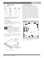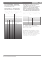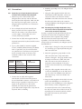
1
LTC 8714, LTC 8715 Series
Instruction Manual
EN Keyboard Port
Expanders
LTC 8714 and 8715 Series | Instruction Manual | Important Safeguards
EN | 2
Important Safeguards
1. Read, Follow, and Retain Instructions - All safety
and operating instructions should be read and
followed before operating the unit. Retain instructions
for future reference.
2. Heed Warnings - Adhere to all warnings on the unit
and in the operating instructions.
3. Attachments - Attachments not recommended by the
product manufacturer should not be used, as they
may cause hazards.
4. Installation Cautions - Do not place this unit on an
unstable stand, tripod, bracket, or mount. The unit
may fall, causing serious injury to a person and
serious damage to the unit. Use only manufacturerrecommended accessories, or those sold with the
product. Mount the unit per the manufacturer's
instructions. Appliance and cart combination should
be moved with care. Quick stops, excessive force, or
uneven surfaces may cause the appliance and cart
combination to overturn.
5. Cleaning - Unplug the unit from the outlet before
cleaning. Follow any instructions provided with the
unit. Generally, using a damp cloth for cleaning is
sufficient. Do not use liquid cleaners or aerosol
cleaners.
6. Servicing - Do not attempt to service this unit
yourself. Opening or removing covers may expose
you to dangerous voltage or other hazards. Refer all
servicing to qualified service personnel.
7. Damage Requiring Service - Unplug the unit from
the main AC power source and refer servicing to
qualified service personnel under the following
conditions:
• When the power supply cord or plug is damaged.
• If liquid has been spilled or an object has fallen
into the unit.
• If the unit has been exposed to water and/or
inclement weather (rain, snow, etc.).
• If the unit does not operate normally, when
following the operating instructions. Adjust only
those controls specified in the operating
instructions. Improper adjustment of other controls
may result in damage, and require extensive work
by a qualified technician to restore the unit to
normal operation.
• If the unit has been dropped or the cabinet
damaged.
• If the unit exhibits a distinct change in
performance, this indicates that service is needed.
8. Replacement Parts - When replacement parts are
required, the service technician should use
replacement parts specified by the manufacturer or
that have the same characteristics as the original part.
Unauthorized substitutions may result in fire,
electrical shock or other hazards.
9. Safety Check - Upon completion of servicing or
repairs to the unit, ask the service technician to
perform safety checks to ensure proper operating
condition.
Bosch Security Systems | May 23, 2005
10. Power Sources - Operate the unit only from the type
of power source indicated on the label. If unsure of
the type of power supply to use, contact your dealer
or local power company.
• For units intended to operate from battery power,
refer to the operating instructions.
• For units intended to operate with External Power
Supplies, use only the recommended approved
power supplies.
• For units intended to operate with a limited power
source, this power source must comply with
EN60950. Substitutions may damage the unit or
cause fire or shock.
• For units intended to operate at 24VAC, normal
input voltage is 24VAC. Voltage applied to the
unit's power input should not exceed 30VAC.
User-supplied wiring, from the 24VAC supply to
unit, must be in compliance with electrical codes
(Class 2 power levels). Do not ground the 24VAC
supply at the terminals or at the unit's power
supply terminals.
11. Coax Grounding - If an outside cable system is
connected to the unit, ensure that the cable system is
grounded. U.S.A. models only - Section 810 of the
National Electrical Code, ANSI/NFPA No.70,
provides information regarding proper grounding of
the mount and supporting structure, grounding of the
coax to a discharge unit, size of grounding
conductors, location of discharge unit, connection to
grounding electrodes, and requirements for the
grounding electrode.
12.Grounding - This unit may be equipped with a 3-wire
grounding plug (a plug with a third pin, for grounding).
This safety feature allows the plug to fit into a
grounding power outlet only. If unable to insert the plug
into the outlet, contact an electrician to arrange
replacement of the obsolete outlet. Do not defeat the
safety purpose of the grounding plug.
• Outdoor equipment should only be connected to
the unit's inputs after this unit has had its grounding
plug connected to a grounded outlet or its ground
terminal properly connected to a ground source.
• The unit's input connectors must be disconnected
from outdoor equipment before disconnecting the
grounding plug or grounding terminal.
• Proper safety precautions such as grounding should
be followed for any outdoor device connected to
this unit.
13. Lightning - For added protection during a lightning
storm, or when this unit is left unattended and unused
for long periods of time, unplug the unit from the
wall outlet and disconnect the cable system. This will
prevent damage to the unit due to lightning and
power line surges.
EN | 3
LTC 8714 and 8715 Series | Instruction Manual | Safety Precautions
For Indoor Product
1. Water and Moisture - Do not use this unit near
water - for example, in a wet basement, in an
unprotected outdoor installation or in any area
classified as a wet location.
2. Object and Liquid Entry - Never push objects of
any kind into this unit through openings, as they
might touch dangerous voltage points or create
short circuits, resulting in a fire or electrical
shock. Never spill liquid of any kind on the unit.
3. Power Cord and Power Cord Protection - For
units intended to operate with 230VAC, 50Hz,
the input and output power cord must comply
with the latest versions of IEC Publication 227 or
IEC Publication 245.
Power supply cords should be routed so they are
not likely to be walked on or pinched. Pay
particular attention to location of cords and plugs,
convenience receptacles, and the point of exit
from the appliance.
4. Overloading - Do not overload outlets and
extension cords; this can result in a risk of fire or
electrical shock.
For Outdoor Product
Power Lines - An outdoor system should not be
located in the vicinity of overhead power lines,
electric lights or power circuits, or where it may
contact such power lines or circuits. When
installing an outdoor system, extreme care should
be taken to keep from touching power lines or
circuits, as this contact might be fatal. U.S.A.
models only - refer to the National Electrical
Code Article 820 regarding installation of CATV
systems.
For Rack-mount Product
1. Ventilation - Do not place this equipment in a
built-in installation or rack, unless proper
ventilation is provided, or the manufacturer's
instructions were followed. The equipment must
not exceed its maximum operating temperature
requirements.
2. Mechanical Loading - When rack-mounting the
equipment, ensure that a hazardous condition is
not created by uneven mechanical loading.
Bosch Security Systems | May 23, 2005
Safety Precautions
CAUTION: TO REDUCE THE RISK OF
ELECTRIC SHOCK, DO NOT REMOVE COVER
(OR BACK). NO USER SERVICEABLE PARTS
INSIDE. REFER SERVICING TO QUALIFIED
SERVICE PERSONNEL.
This symbol indicates the presence of
uninsulated “dangerous voltage” within the
product’s enclosure that can cause an electric
shock.
This symbol indicates the presence of
important operating and maintenance
(servicing) instructions in the literature
accompanying the appliance.
Installation should be performed by qualified
service personnel only in accordance with the
National Electrical Code or applicable local
codes.
Power Disconnect. Units with or without
ON-OFF switches have power supplied to the
unit whenever the power cord is inserted into the
power source; however, the unit is operational
only when the ON-OFF switch is in the ON
position. The power cord is the main power
disconnect for all units.
LTC 8714 and 8715 Series | Instruction Manual | FCC & ICES Information
FCC & ICES INFORMATION
(U.S.A. and Canadian Models Only)
This device complies with part 15 of the FCC Rules. Operation is
subject to the following two conditions:
(1)
This device may not cause harmful interference, and
(2)
This device must accept any interference received,
including interference that may cause undesired
operation.
NOTE: This equipment has been tested and found to comply
with the limits for a Class B digital device, pursuant to Part 15 of
the FCC Rules and ICES-003 of Industry Canada. These limits
are designed to provide reasonable protection against harmful
interference when the equipment is operated in a residential
installation. This equipment generates, uses and can radiate radio
frequency energy, and if not installed and used in accordance
with the instructions, may cause harmful interference to radio
communications. However, there is no guarantee that interference
will not occur in a particular installation. If this equipment does
cause harmful interference to radio or television reception, which
can be determined by turning the equipment off and on, the user
is encouraged to try to correct the interference by one or
more of the following measures:
• Reorient or relocate the receiving antenna.
• Increase the separation between the equipment and receiver.
• Connect the equipment into an outlet on a circuit different
from that to which the receiver is connected.
• Consult the dealer, or an experienced radio/TV technician for
help.
Intentional or unintentional changes or modifications, not
expressly approved by the party responsible for compliance, shall
not be made. Any such changes or modifications could void the
user’s authority to operate the equipment.The user may find the
following booklet, prepared by the Federal Communications
Commission, helpful: How to Identify and Resolve Radio-TV
Interference Problems. This booklet is available from the U.S.
Government Printing Office, Washington, DC 20402, Stock No.
004-000-00345-4.
Bosch Security Systems | May 23, 2005
EN | 4
LTC 8714 and 8715 Series | Instruction Manual | Table of Contents
EN | 5
Table of Contents
Important Safeguards . . . . . . . . . . . . . . . . . . . . . . . . . . . . . . . . . . . . . . . . . . . . . . . . . . . . . . . . . . . . . . . . . .2
FCC & ICES Information . . . . . . . . . . . . . . . . . . . . . . . . . . . . . . . . . . . . . . . . . . . . . . . . . . . . . . . . . . . . . .4
1
UNPACKING . . . . . . . . . . . . . . . . . . . . . . . . . . . . . . . . . . . . . . . . . . . . . . . . . . . . . . . . . . . . . . . . . .6
2
SERVICE . . . . . . . . . . . . . . . . . . . . . . . . . . . . . . . . . . . . . . . . . . . . . . . . . . . . . . . . . . . . . . . . . . . . .6
3
DESCRIPTION . . . . . . . . . . . . . . . . . . . . . . . . . . . . . . . . . . . . . . . . . . . . . . . . . . . . . . . . . . . . . . . .6
4
INSTALLATION . . . . . . . . . . . . . . . . . . . . . . . . . . . . . . . . . . . . . . . . . . . . . . . . . . . . . . . . . . . . . . .7
4.1
Power . . . . . . . . . . . . . . . . . . . . . . . . . . . . . . . . . . . . . . . . . . . . . . . . . . . . . . . . . . . . . . . . . . . . . . . . .7
4.2
Mounting . . . . . . . . . . . . . . . . . . . . . . . . . . . . . . . . . . . . . . . . . . . . . . . . . . . . . . . . . . . . . . . . . . . . . .7
4.3
Cover Removal . . . . . . . . . . . . . . . . . . . . . . . . . . . . . . . . . . . . . . . . . . . . . . . . . . . . . . . . . . . . . . . . .7
4.4
DIP Switch Settings . . . . . . . . . . . . . . . . . . . . . . . . . . . . . . . . . . . . . . . . . . . . . . . . . . . . . . . . . . . . . .7
4.5
Connections . . . . . . . . . . . . . . . . . . . . . . . . . . . . . . . . . . . . . . . . . . . . . . . . . . . . . . . . . . . . . . . . . . . .9
5
OPERATION . . . . . . . . . . . . . . . . . . . . . . . . . . . . . . . . . . . . . . . . . . . . . . . . . . . . . . . . . . . . . . . . .10
6
ILLLUSTRATIONS . . . . . . . . . . . . . . . . . . . . . . . . . . . . . . . . . . . . . . . . . . . . . . . . . . . . . . . . . . . .11
Bosch Security Systems | May 23, 2005
EN | 6
LTC 8714 and 8715 Series | Instruction Manual | Unpacking
1
UNPACKING
3
Unpack carefully. This is electronic equipment and
should be handled carefully.
Check for the following items:
•
Verify the model number of the unit.
•
One (1) cable assembly with 9-pin D-sub
connectors.
If an item appears to have been damaged in shipment,
replace it properly in its carton and notify the shipper.
If any items are missing, notify your Bosch Security
Systems, Inc. Sales Representative or Customer
Service.
The shipping carton is the safest container in which the
unit may be transported. Save it for possible future use.
2
SERVICE
If the unit needs servicing, contact the nearest Bosch
Security Systems Service Center for authorization to
return and shipping instructions.
Service Centers
USA
Phone:
800-366-2283 or 717-735-6638
Fax:
800-366-1329 or 717-735-6639
CCTV Spare Parts
Phone:
800-894-5215 or 408-956-3853 or 3854
Fax:
408-957-3198
E-mail:
[email protected]
Canada
Phone:
514-738-2434
Europe, Middle East & Asia Pacific Region
Phone:
32-1-440-0711
For additional information, see www.boschsecurity.com.
NOTE: Grounded wrist straps must be worn and
proper ESD safety precautions observed when
handling the electrostatic-sensitive printed circuit
boards.
WARNING: Electrostatic-sensitive
device. Use proper CMOS/
MOSFET handling precautions to
avoid electrostatic discharge.
Bosch Security Systems | May 23, 2005
ATTENTION
OBSERVE PRECAUTIONS
FOR HANDLING
ELECTROSTATIC
SENSITIVE
DEVICES
DESCRIPTION
This publication provides instructions for installing the
LTC 8714 Series and LTC 8715 Series Keyboard Port
Expanders in an Allegiant® Series matrix
switcher/controller system.
A single LTC 8714 Series unit can be used to interface
up to eight Allegiant Series keyboards with an
Allegiant system. A single LTC 8715 Series unit is used
to interface up to four (4) LTC 8714 Series expanders in
a system. Multiple LTC 8715 Series expanders can be
used along with multiple LTC 8714 Series expanders to
provide up to 64 keyboards in a system. The actual
number of units that can be used in a system depends
upon the model of the Allegiant system. The table
below lists the various Allegiant models and the
maximum number of keyboard expander units and
Allegiant Series keyboards that can be connected in a
system.
Allegiant System Capacities
Allegiant
Series
Model
Max Number
of Keyboards
in System
Max Number
of LTC 8714
Supported
Max Number
of LTC 8715
Supported
LTC 8600
16
1
0
LTC 8800
32
3
1
LTC 8900
64
7
3
NOTE: The above table assumes 8 system keyboards
are connected directly into the Allegiant CPU bay
keyboard ports.
For each Allegiant Series keyboard used in an
"expanded configuration," one LTC 8557 Series
Keyboard Extension Kit (not included) is required.
Each keyboard port expander is supplied with a single
interface cable. This cable is used to connect the port
expander to either the Allegiant CPU bay or to
another port expander. The LTC 8557 Series Kit is
then used to connect the expanded keyboards to the
LTC 8714 Series Port Expander(s). See Typical
Application Diagrams found at the end of this manual.
EN | 7
LTC 8714 and 8715 Series | Instruction Manual | Installation
4
4.1
4.4
INSTALLATION
Power
Model
No.1
LTC 8714/60
LTC 8714/50
LTC 8715/60
LTC 8715/50
Rated
Voltage
120 VAC,
50/60 Hz
220-240 VAC,
50/60 Hz
120 VAC,
50/60 Hz
220-240 VAC,
50/60 Hz
Voltage
Range
105 to 130
Nominal
Power2
10 W
198 to 264
10 W
105 to 130
10 W
198 to 264
10 W
1
The model number and operating voltage are shown on the
bottom of the unit. These units are supplied with grounded
power cords; grounding must not be defeated.
2
At rated voltage.
4.2
DIP Switch Settings
The LTC 8714 Series Keyboard Port Expanders and
the LTC 8715 Expander communicate with the
Allegiant Series main bay and the Allegiant Series
keyboards via RS-485 communications. The LTC 8714
Series Keyboard Port Expanders and the LTC 8715
Series Expander contain internal DIP switches which
can be used to set the communication parameters.
The cover must be removed if the DIP switches need
to be changed from their factory default settings. See
FIGURE 1. The following table summarizes the DIP
switch settings and their associated features. Note that
after changing any of the DIP switch settings, the AC
power must be turned off and on before the changes
can take effect.
Mounting
These units are supplied as desk top units. For rack
mounting, the LTC 9101/00 rack-mount kit is available.
These units are half-rack units.
4.3
Cover Removal
WARNING: Removal of the cover should
only be performed by qualified service
personnel–not user serviceable. The unit
should always be unplugged, before
removing the cover and remain unplugged
while the cover is removed.
The cover is fastened to the chassis by two screws on
the bottom near the rear of the unit. Disassembly is as
shown in FIGURE 1.
Slide Cover Back
Figure 2 Location of DIP Switches
Remove Screws from
Bottom Rear Corners
(2) Places
Figure 1 Top Cover Removal
Bosch Security Systems | May 23, 2005
EN | 8
LTC 8714 and 8715 Series | Instruction Manual | Installation
4.4.1 DIP Switch Settings - LTC 8714 Series
S401 DIP Switch: Verify that switches 1, 2, and 3
are ON and all others are OFF.
S402 DIP Switches 1 to 5: Baud rate and poll type
settings must match those on the Allegiant Series
keyboards. Group number should be selected to agree
with capacity and configuration settings associated with
specific Allegiant series system being used.
Switch Number
1
OFF
ON
2
OFF
OFF
OFF
OFF
OFF
OFF
OFF
OFF
ON
ON
ON
ON
ON
ON
ON
ON
3
OFF
OFF
OFF
OFF
ON
ON
ON
ON
OFF
OFF
OFF
OFF
ON
ON
ON
ON
4
OFF
OFF
ON
ON
OFF
OFF
ON
ON
OFF
OFF
ON
ON
OFF
OFF
ON
ON
5
OFF
ON
OFF
ON
OFF
ON
OFF
ON
OFF
ON
OFF
ON
OFF
ON
OFF
ON
Function
Allegiant Keyboard
Baud Rate
9600 (Factory Default
Setting)
19200
Group Number
0 (Kbd 1– 8)
1 (Kbd 9–16)
(Factory Default
Setting)
2 (Kbd 17–24)
3 (Kbd 25–32)
4 (Kbd 33– 40)
5 (Kbd 41– 48)
6 (Kbd 49–56)
7 (Kbd 57– 64)
8 (Kbd 65–72)
9 (Kbd 73– 80)
10 (Kbd 81– 88)
11 (Kbd 89–96)
12 (Kbd 97–104)
13 (Kbd 105–112)
14 (Kbd 113 –120)
Reserved
Bosch Security Systems | May 23, 2005
S402 DIP Switches 6 to 8: These switches determine
the data polling format that will be used to
communicate with the keyboards. The 4 Poll selection
would typically be used only in LTC 8600 Series
systems using fixed speed receiver/driver equipped
cameras. The 8 Poll selection would typically be used
in LTC 8800 and LTC 8900 systems with fixed speed
receiver/drivers. The 6 Poll selection should be used in
any system where Allegiant Series keyboards are being
used to control variable speed AutoDome® Series
cameras.
Switch Number
6
OFF
OFF
ON
7
OFF
ON
OFF
ON
ON
8
Poll Type
4 POLL
8 POLL
6 POLL
(Factory Default Setting)
Reserved
Reserved
4.4.2 DIP Switch Settings - LTC 8715 Series
S401 DIP Switch: Verify that switches 1, 2, and 3 are
ON and all others are OFF.
S402 DIP Switch: Verify that switches 1, 2, and 3 are
ON and all others are OFF if the LTC 8715 will have
LTC 8714 units connected directly to it. Verify that
switches 1, 2, 3, and 5 are ON and all others are OFF
if the LTC 8715 will have other LTC 8715 units
connected directly to it (see FIGURE 11).
LTC 8714 and 8715 Series | Instruction Manual | Installation
4.5
6. Similarly, repeat Step 5 for each Allegiant Series
keyboard.
Connections
4.5.1 Expanding up to Eight Keyboards Using the
LTC 8714 Series Keyboard Port Expander
1. Make sure power is turned OFF on the
Allegiant Series main bay and the LTC 8714
Series Keyboard Port Expander. Make sure that
the external power supply used to power the
Allegiant Series keyboards is not connected to
a wall outlet.
2. For each keyboard used with the LTC 8714
Series, one LTC 8557 kit is required. The
LTC 8557 kit consists of two junction boxes,
a power supply, a barrel plug cord, and a
3 meter (10 ft) keyboard cable.
3. Connect the 3m (10ft) cable supplied with the
keyboard between the keyboard and the remote
junction box.
4. Up to 1.5km (5000ft) of customer supplied
0.5mm2 (24AWG) shielded twisted pair (Belden
9841 or equivalent) may be run between the
two junction boxes. Connection to the junction
boxes are made to three of the four screw
terminals as follows. Note reversal to data
connections.
Terminal
Number
1
2
3
4
Remote
Keyboard
Junction Box
Spare
+
–
Shield
EN | 9
Local
Junction Box
Spare
–
+
Shield
5. Connect the 3m (10ft) cable supplied
with the LTC 8557 kit between the junction
box and the PORT connector on the LTC 8714
Keyboard port expander. Connect the power
supply to the junction box at the remote
keyboard site. Verify that the junction box
power LED indicator lights. Also verify that the
keyboard LEDs are flashing.
Bosch Security Systems | May 23, 2005
7. Using the cable supplied with the LTC 8714
Series Keyboard Port Expander, connect one
end of the cable to the connector marked
SYSTEM on the LTC 8714 Series unit. Connect
the other end of the cable to the connector
marked COMM2 on the Allegiant Series system
(see FIGURE 9).
4.5.2 Expanding Beyond Eight Keyboards Using
the LTC 8714 Series Keyboard Port Expanders
with the LTC 8715 Series Expander
In order to expand beyond eight keyboards, the use
of an LTC 8715 Series unit in conjunction with an
LTC 8714 Series unit is required. Using multiple
LTC 8715 units, the remote keyboards can be
expanded to 120. Note that the maximum number
of keyboards may be limited by the Allegiant system.
See FIGURE 10.
1. Follow Steps 1 through 7 in the previous section
for connecting up to eight keyboards using the
LTC 8714 Series unit.
2. Select the appropriate group number on the
LTC 8714 Series unit via dip switch S402,
switches 2 through 5. The group number must
be unique and must not conflict with other
LTC 8714 units or the local keyboards (i.e.,
keyboards connected directly to the ports
located on the main CPU bay) in the Allegiant
system.
3. Using the cables supplied with the LTC 8714,
connect the SYSTEM port on the LTC 8714 to
any one of the four PORTS on the LTC 8715
unit. Repeat steps 1 and 2 for all LTC 8714
Series units.
4. Using the cable supplied with the LTC 8715 unit,
connect the SYSTEM port on the LTC 8715
Series unit to the COMM2 port on the Allegiant
Series main bay. In this configuration, up to
32 remote keyboards can be connected using
four LTC 8714 units and one LTC 8715 unit. To
expand beyond 32 remote keyboards, another
tier of LTC 8715 units may be used (see
FIGURE 11).
LTC 8714 and 8715 Series | Instruction Manual | Operation
5
OPERATION
1. Turn on the Allegiant Series main bay, the
LTC 8714 Series Keyboard Port Expander,
and the LTC 8715 Series Expander. The
power LEDs on the LTC 8714 Series unit
and the LTC 8715 Series unit should be on.
2. Note that the system Tx LED on the front panel
of the LTC 8714 Series Keyboard Port Expander
will flash whenever data is being sent to the
Allegiant system (or to an LTC 8715 Series
Expander) from the LTC 8714 Series Keyboard
Port Expander. The system Rx LED will flash
whenever data is being received from the
Allegiant system (or from an LTC 8715 Series
Expander). Data is also occasionally sent from
the Allegiant system to reflect applicable system
changes and on an occasional basis to maintain
current system status.
The port LEDs on the LTC 8714 Series
Keyboard Port Expander will indicate active
data communication to a connected keyboard.
LEDs on the front panel of an LTC 8715 Series
Expander will indicate communication between
the Allegiant system and the associated
LTC 8714 Series Keyboard Port Expanders
that are connected to it.
Bosch Security Systems | May 23, 2005
EN | 10
EN | 11
LTC 8714 and 8715 Series | Instruction Manual | Illustrations
6
ILLUSTRATIONS
PORT 1 PORT 2
POWER
Rx
PORT 3 PORT 4 PORT 5 PORT 6 PORT 7 PORT 8
Tx
ACTIVE ACTIVE ACTIVE ACTIVE ACTIVE ACTIVE ACTIVE ACTIVE
SYSTEM
PORT 1
PORT 2
PORT 3
PORT 4
PORT 5
PORT 6
PORT 7
SYSTEM
PORT 8
Figure 3 LTC 8714 Series - Front and Back Panels
5
6
5
4
3
2
4
2
1
1
9
Figure 4 Keyboard Ports 1 through 8
Pin
1
2
3
4
5
6
3
Function
Ground
Ground
–Data
+Data
Ground
Ground
Bosch Security Systems | May 23, 2005
8
7
6
Figure 5 System Port - Female 9-pin
D-sub Connector
Pin
1
2
3
4
5
6
7
8
9
Function
Chassis Ground
+Tx (Transmit)
–Tx (Transmit)
+Rx (Receive)
–Rx (Receive)
Ground
Ground
Ground
Ground
EN | 12
LTC 8714 and 8715 Series | Instruction Manual | Illustrations
Rx
Rx
Tx
Tx
KB-EXP2
KB-EXP1
PORT 2
PORT 1
Tx
KB-EXP3
PORT 3
POWER
Rx
Rx
Rx
Tx
Tx
KB-EXP4
SYSTEM
SYSTEM
PORT 4
Figure 6 LTC 8715 Series - Front and Back Panels
5
4
9
3
8
2
7
1
5
6
9
Pin
1
2
3
4
5
6
7
8
9
Function
Chassis Ground
+Tx (Transmit)
–Tx (Transmit)
+Rx (Receive)
–Rx (Receive)
Ground
Ground
Ground
Ground
9-pin Male
Main CPU
Comm 2
Connector
1
2
3
4
5
6
7
8
9
9-pin Male
Expander
System
Connector
No Connection
4
5
2
3
No Connection
No Connection
No Connection
No Connection
Expander-to-main CPU Bay Cable Pinouts
Bosch Security Systems | May 23, 2005
3
8
2
7
1
6
Figure 8 System Port - Female 9-pin
D-sub Connector
Figure 7 Ports 1 through 4 - Female 9-pin
D-sub Connector
Pin
1
2
3
4
5
6
7
8
9
4
Function
Chassis Ground
+Tx (Transmit)
–Tx (Transmit)
+Rx (Receive)
–Rx (Receive)
Ground
Ground
Ground
Ground
EN | 13
LTC 8714 and 8715 Series | Instruction Manual | Illustrations
LTC 8600 Series or LTC 8800 Series Allegiant Main Bay (Rear View)
Comm 2 Port
Cable Supplied
with LTC 8714
Series Keyboard
Port Expanders
LTC 8714 Series
Keyboard Port
Expanders (Rear View)
PORT 1
PORT 2
PORT 3
PORT 4
PORT 5
PORT 6
PORT 8
PORT 7
Cable Supplied with
LTC 8557 Kit
Keyboards 9-16
Cable Supplied
with Keyboard
LTC 8557
Remote Keyboard
Site Junction Box
LTC 8557
Local CPU
Site Junction Box
User Supplied
Shielded Twisted Pair
Power Pack
SYSTEM
Cable Supplied
with Keyboard
LTC 8557
Remote Keyboard
Site Junction Box
LTC 8557
Local CPU
Site Junction Box
User Supplied
Shielded Twisted Pair
Power Pack
Keyboard
Keyboard
Figure 9 Typical LTC 8714 Series Keyboard Port Expander Application
Up to Eight Allegiant Series Keyboards
Bosch Security Systems | May 23, 2005
EN | 14
LTC 8714 and 8715 Series | Instruction Manual | Illustrations
LTC 8800 Series Allegiant Main Bay (Rear View)
Keyboards 1–8
Comm 2 Port
Cable Supplied with
LTC 8715 Series
Expanders
LTC 8715 Series
Expanders (Rear View)
PORT 1
PORT 2
PORT 3
PORT 4
Cable Supplied
with LTC 8714
SYSTEM
LTC 8714 Series Expanders (Rear View)
PORT 1
PORT 2 PORT 3 PORT 4
PORT 5
PORT 6
PORT 7
PORT 8
SYSTEM
PORT 1
Keyboards
9–16
PORT 1
PORT 2 PORT 3 PORT 4
PORT 5
PORT 6
PORT 7
PORT 8
SYSTEM
Keyboards
25–32
PORT 2 PORT 3 PORT 4
PORT 5
PORT 6
PORT 7
PORT 8
SYSTEM
Keyboards
17–24
Figure 10 Typical LTC 8714 Series Keyboard Port Expander & LTC 8715 Series Expander Application
Bosch Security Systems | May 23, 2005
EN | 15
LTC 8714 and 8715 Series | Instruction Manual | Illustrations
LTC 8900 Series Allegiant CPU (Rear View)
1
2
4
3
KEYBOARD
5
7
6
8
Keyboards 1– 8
CONTROLLER
COM1
CONSOLE
COM2
BIPHASE
ALARM
LAN
Comm 2 Port
Cable supplied with
LTC 8715 Series
Expanders
LTC 8715 Series
Expanders (Rear View)
PORT 1
PORT 2
PORT 3
PORT 4
PORT 1
SYSTEM
PORT 3
SYSTEM
PORT 4
PORT 1
PORT 2
PORT 3
PORT 4
SYSTEM
PORT 2
PORT 3
PORT 4
SYSTEM
Keyboards
105–120
Keyboards
9–40
PORT 1
PORT 2
PORT 2
PORT 3
PORT 4
SYSTEM
PORT 1
LTC 8714 Seies
Expanders (Rear View)
Keyboards
41–72
Keyboards
73–104
*Dotted line indicates future LTC 8900 capacity
Figure 11 Typical Installation for More than 32 Remote Keyboards
Bosch Security Systems | May 23, 2005
Americas
Bosch Security Systems
130 Perinton Parkway
Fairport, New York, 14450, USA
Phone: +1 (585) 223 4060
+1 800 289 0096
[email protected]
http://www.boschsecurity.us
Europe, Middle East, Africa
Bosch Security Systems B.V.
P.O. Box 80002
5600 JB Eindhoven, The Netherlands
Phone: +31 (0) 40 27 83955
Fax:
+31 (0) 40 27 86668
[email protected]
http://www.boschsecurity.com
© 2005 Bosch Security Systems GmbH
F01U009394_01 05-21 | May 23, 2005 | Data subject to change without notice.
Asia-Pacific
Bosch Security Systems Pte Ltd
38C Jalan Pemimpin
Singapore 577180
Phone: +65 6319 3450
Fax:
+65 6319 3499
[email protected]
http://www.boschsecurity.com