1
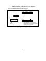
To our customers,
Old Company Name in Catalogs and Other Documents
On April 1st, 2010, NEC Electronics Corporation merged with Renesas Technology
Corporation, and Renesas Electronics Corporation took over all the business of both
companies. Therefore, although the old company name remains in this document, it is a valid
Renesas Electronics document. We appreciate your understanding.
Renesas Electronics website: http://www.renesas.com
April 1st, 2010
Renesas Electronics Corporation
Issued by: Renesas Electronics Corporation (http://www.renesas.com)
Send any inquiries to http://www.renesas.com/inquiry.
Notice
1.
2.
3.
4.
5.
6.
7.
All information included in this document is current as of the date this document is issued. Such information, however, is
subject to change without any prior notice. Before purchasing or using any Renesas Electronics products listed herein, please
confirm the latest product information with a Renesas Electronics sales office. Also, please pay regular and careful attention to
additional and different information to be disclosed by Renesas Electronics such as that disclosed through our website.
Renesas Electronics does not assume any liability for infringement of patents, copyrights, or other intellectual property rights
of third parties by or arising from the use of Renesas Electronics products or technical information described in this document.
No license, express, implied or otherwise, is granted hereby under any patents, copyrights or other intellectual property rights
of Renesas Electronics or others.
You should not alter, modify, copy, or otherwise misappropriate any Renesas Electronics product, whether in whole or in part.
Descriptions of circuits, software and other related information in this document are provided only to illustrate the operation of
semiconductor products and application examples. You are fully responsible for the incorporation of these circuits, software,
and information in the design of your equipment. Renesas Electronics assumes no responsibility for any losses incurred by
you or third parties arising from the use of these circuits, software, or information.
When exporting the products or technology described in this document, you should comply with the applicable export control
laws and regulations and follow the procedures required by such laws and regulations. You should not use Renesas
Electronics products or the technology described in this document for any purpose relating to military applications or use by
the military, including but not limited to the development of weapons of mass destruction. Renesas Electronics products and
technology may not be used for or incorporated into any products or systems whose manufacture, use, or sale is prohibited
under any applicable domestic or foreign laws or regulations.
Renesas Electronics has used reasonable care in preparing the information included in this document, but Renesas Electronics
does not warrant that such information is error free. Renesas Electronics assumes no liability whatsoever for any damages
incurred by you resulting from errors in or omissions from the information included herein.
Renesas Electronics products are classified according to the following three quality grades: “Standard”, “High Quality”, and
“Specific”. The recommended applications for each Renesas Electronics product depends on the product’s quality grade, as
indicated below. You must check the quality grade of each Renesas Electronics product before using it in a particular
application. You may not use any Renesas Electronics product for any application categorized as “Specific” without the prior
written consent of Renesas Electronics. Further, you may not use any Renesas Electronics product for any application for
which it is not intended without the prior written consent of Renesas Electronics. Renesas Electronics shall not be in any way
liable for any damages or losses incurred by you or third parties arising from the use of any Renesas Electronics product for an
application categorized as “Specific” or for which the product is not intended where you have failed to obtain the prior written
consent of Renesas Electronics. The quality grade of each Renesas Electronics product is “Standard” unless otherwise
expressly specified in a Renesas Electronics data sheets or data books, etc.
“Standard”:
8.
9.
10.
11.
12.
Computers; office equipment; communications equipment; test and measurement equipment; audio and visual
equipment; home electronic appliances; machine tools; personal electronic equipment; and industrial robots.
“High Quality”: Transportation equipment (automobiles, trains, ships, etc.); traffic control systems; anti-disaster systems; anticrime systems; safety equipment; and medical equipment not specifically designed for life support.
“Specific”:
Aircraft; aerospace equipment; submersible repeaters; nuclear reactor control systems; medical equipment or
systems for life support (e.g. artificial life support devices or systems), surgical implantations, or healthcare
intervention (e.g. excision, etc.), and any other applications or purposes that pose a direct threat to human life.
You should use the Renesas Electronics products described in this document within the range specified by Renesas Electronics,
especially with respect to the maximum rating, operating supply voltage range, movement power voltage range, heat radiation
characteristics, installation and other product characteristics. Renesas Electronics shall have no liability for malfunctions or
damages arising out of the use of Renesas Electronics products beyond such specified ranges.
Although Renesas Electronics endeavors to improve the quality and reliability of its products, semiconductor products have
specific characteristics such as the occurrence of failure at a certain rate and malfunctions under certain use conditions. Further,
Renesas Electronics products are not subject to radiation resistance design. Please be sure to implement safety measures to
guard them against the possibility of physical injury, and injury or damage caused by fire in the event of the failure of a
Renesas Electronics product, such as safety design for hardware and software including but not limited to redundancy, fire
control and malfunction prevention, appropriate treatment for aging degradation or any other appropriate measures. Because
the evaluation of microcomputer software alone is very difficult, please evaluate the safety of the final products or system
manufactured by you.
Please contact a Renesas Electronics sales office for details as to environmental matters such as the environmental
compatibility of each Renesas Electronics product. Please use Renesas Electronics products in compliance with all applicable
laws and regulations that regulate the inclusion or use of controlled substances, including without limitation, the EU RoHS
Directive. Renesas Electronics assumes no liability for damages or losses occurring as a result of your noncompliance with
applicable laws and regulations.
This document may not be reproduced or duplicated, in any form, in whole or in part, without prior written consent of Renesas
Electronics.
Please contact a Renesas Electronics sales office if you have any questions regarding the information contained in this
document or Renesas Electronics products, or if you have any other inquiries.
(Note 1) “Renesas Electronics” as used in this document means Renesas Electronics Corporation and also includes its majorityowned subsidiaries.
(Note 2) “Renesas Electronics product(s)” means any product developed or manufactured by or for Renesas Electronics.
User’s Manual
Connection of H8S/2158F
E10A Emulator
with User System
HS2158KCM01H
HS2158KCI01H
Version 1.50
1. Connecting the E10A Emulator with the User system
To connect the E10A emulator (hereafter referred to as emulator), an H-UDI port connector must
be installed on the user system to connect the user system interface cable. When designing the
user system, refer to the recommended circuit between the H-UDI port connector and the MCU.
Before designing the user system, be sure to read the H8S/2158F E10A user’s manual and the
hardware manual of the related MCU.
2
2. Installing the H-UDI Port Connector on the User System
Table 2.1 shows the H-UDI port connector for the emulator.
Table 2.1 Recommended Connector
Type Number
Manufacturer
Specifications
2514-6002xx*
3M Limited
14-pin straight type
Note: xx means plated version.
Note: Do not install any components within 3 mm of the H-UDI port connector.
3
3. Pin Arrangement of the H-UDI Port Connector
Figure3.1 shows the pin arrangement of the H-UDI port connector.
Pin 1 mark
H-UDI port connector
Pin 14
Pin 7
Pin 8
Pin 1
Pin No.
MCU
Pin Name
1
ETCK
Input
2
ETRST#
Input
3
ETDO
Output
4
RES# *2
Input
5
ETMS
Input
6
ETDI
Input
7
RES# *2
Output
8 to 10
GND *3
Input/Output *1
12 to 14
11
Vcc *4
Top view
Pin 1 mark
Note: 1. Input or output from the user system.
2. The symbol (#) means that the signal is active-low.
3. By detecting GND on the user system side, connection or
disconnection with the user system can be determined.
4. Connect Vcc with the Vcc of the MCU.
Figure 3.1 Pin Arrangement of the H-UDI Port Connector
4
4. Example of Emulator Connection
The figure shown below is an example of connecting the user system to the emulator.
14-pin connector with
a 2.54-mm pitch
(3M Limited: 2514-6002)
Vcc
Pulled-up at 4.7 kΩ
MCU
11
FWE
1
ETCK
2
ETRST#
3
ETDO
5
ETMS
6
ETDI
4
User logic
7
RES#
MD2#
8 to 10
12 to 14
E10A pin No.
User system
· RES# of pin 4 of the H-UDI port connector is a signal line in which the emulator outputs signals to the MCU.
An AND operation must be performed between RES# (pin 4) and the user system reset circuit for the signal
line connected to the MCU.
· RES# of pin 7 of the H-UDI port connector is a signal line in which the emulator monitors the RES# signal of
the MCU. The RES# must be pulled up before it is connected to pin 7 of the H-UDI port connector.
Figure 4.1 Example of Emulator Connection
5
Notes: 1. ETRST#, ETCK, ETMS, ETDO, and ETDI are used by the emulator. Pull up
and connect the emulator and MCU pins.
MCU
H-UDI port
connector
Vcc
4.7 kΩ
Pins 1, 2, 3, 5, and 6
Figure 4.2 Connection of Emulator and MCU
6
2.
If the emulator is not connected to the user system, pull up pin MD2# of the
MCU. When the emulator is connected to the user system, ground the MD2#.
MCU
Vcc
The emulator is not connected
to the user system.
4.7 kΩ
MD2#
MCU
MD2#
The emulator is connected
to the user system.
Figure 4.3 E10A Emulator and Pin MD2#
7
3.
RES# of pin 4 of the H-UDI port connector is a signal line in which the emulator
outputs signals to the MCU. An AND operation must be performed between
RES# and the user system reset circuit for the signal line connected to the MCU.
RES# of pin 7 of the H-UDI port connector is a signal line in which the emulator
monitors the RES# signal of the MCU.
The RES# must be pulled up before it is connected to pin 7 of the H-UDI port
connector.
Vcc
4.7 kΩ
User
logic
MCU
H-UDI port
connector
Vcc
Pin 4
4.7 kΩ
Pin 7
Figure 4.4 Examples of Reset Circuits
4.
Pin FWE must be pulled up if the emulator is connected to the user system.
Vcc
The emulator is connected
to the user system.
4.7 kΩ
MCU
FWE
Figure 4.5 Connection of Pin FWE
5.
6.
Ground pins 8 to 10, and 12 to 14 of the H-UDI port connector.
Pin 11 of the H-UDI port connector must be connected to the user system Vcc
(power supply). The amount of voltage permitted to input to the H-UDI port
connector must be within the guaranteed range of the microcomputer.
8
7.
Figure 4.6 shows the interface circuit in the emulator. Use this figure as a
reference to decide the pull-up resistance value.
H-UDI port
connector
on the user
system
Emulator control circuit
Vcc
11
Vcc
1
2
4
5
6
ETCK
ETRST#
RES#
ETMS
ETDI
3
7
ETDO
RES#
4.7 kΩ x 7
22 Ω x 5
HD74LV125A
Vcc
3.3 V
MCU
HD74LVTH244
22 Ω x 2
Vcc
Figure 4.6 Interface Circuit in the Emulator (Reference)
9