1
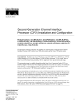
®
T200 T1 HDSL4 Repeater (H4R)
Installation and Maintenance Practice
Part Number - 61223441L1-5C
H R
1223441L1
PWR
LP1
NET
LP2
LP1
CUST
LP2
LL / RL
(Y) (G)
CLEI: T1R6T86D_ _
October 2004
T200 H4R Installation and Maintenance Practice
Trademarks
Any brand names and product names included in this manual are trademarks, registered trademarks, or trade names of their respective holders.
To the Holder of the Manual
The contents of this publication are current as of the date of publication. ADTRAN reserves the
right to change the contents without prior notice.
In no event will ADTRAN be liable for any special, incidental, or consequential damages or for
commercial losses even if ADTRAN has been advised thereof as a result of issue of this publication.
®
901 Explorer Boulevard
P.O. Box 140000
Huntsville, AL 35814-4000
(256) 963-8000
©2004 ADTRAN, Inc.
All Rights Reserved.
Printed in U.S.A.
ii
61223441L1-5C
T200 H4R Installation and Maintenance Practice
Revision History
Revision
Date
C
October 2004
Description of Changes
Updated to add Bad Splice Detect and Fast Retrain feature
descriptions
Conventions
The following typographical conventions are used in this document:
This font indicates a cross-reference link. First-time references to tables and figures are shown in
this font.
This font indicates screen menus, fields, and parameters.
THIS FONT indicates keyboard keys (ENTER, ESC, ALT). Keys that are to be pressed simultaneously
are shown with a plus sign (ALT+X indicates that the ALT key and X key should be pressed at the
same time).
This font indicates references to other documentation and is also used for emphasis.
This font indicates on-screen messages and prompts.
This font indicates text to be typed exactly as shown.
This font indicates silkscreen labels or other system label items.
This font is used for strong emphasis
NOTE
Notes inform the user of additional but essential information or features.
CAUTION
Cautions inform the user of potential damage, malfunction, or disruption to equipment, software, or environment.
WARNING
Warnings inform the user of potential bodily pain, injury, or death.
61223441L1-5C
iii
T200 H4R Installation and Maintenance Practice
Training
ADTRAN offers training courses on our products. These courses include overviews on product
features and functions while covering applications of ADTRAN’s product lines. ADTRAN
provides a variety of training options, including customized training and course taught at our facilities or at customer sites. For more information about training, please contact us.
iv
Training Phone:
800-615-1176, ext. 7500
Training Fax:
256-963-6700
Training Email:
[email protected]
61223441L1-5C
Contents
1. General . . . . . . . . . . . . . . . . . . . . . . . . . . . . . . . . . . . . . . . . . . . . . . . . . . . . . . . . . . . . . . . . . . . . . . . . . . . . . . . 1
2. Description. . . . . . . . . . . . . . . . . . . . . . . . . . . . . . . . . . . . . . . . . . . . . . . . . . . . . . . . . . . . . . . . . . . . . . . . . . . .
Features . . . . . . . . . . . . . . . . . . . . . . . . . . . . . . . . . . . . . . . . . . . . . . . . . . . . . . . . . . . . . . . . . . . . . . . . . . .
Bad Splice Detection Feature . . . . . . . . . . . . . . . . . . . . . . . . . . . . . . . . . . . . . . . . . . . . . . . . . . . . . . .
View Splice Results Screen . . . . . . . . . . . . . . . . . . . . . . . . . . . . . . . . . . . . . . . . . . . . . . . . . . . . . . . . .
Fast Retrain Feature . . . . . . . . . . . . . . . . . . . . . . . . . . . . . . . . . . . . . . . . . . . . . . . . . . . . . . . . . . . . . .
Compatibility . . . . . . . . . . . . . . . . . . . . . . . . . . . . . . . . . . . . . . . . . . . . . . . . . . . . . . . . . . . . . . . . . . . . . . .
Compliance . . . . . . . . . . . . . . . . . . . . . . . . . . . . . . . . . . . . . . . . . . . . . . . . . . . . . . . . . . . . . . . . . . . . . . . .
2
2
2
3
3
4
5
3. Installation . . . . . . . . . . . . . . . . . . . . . . . . . . . . . . . . . . . . . . . . . . . . . . . . . . . . . . . . . . . . . . . . . . . . . . . . . . . . 6
Shipping Contents . . . . . . . . . . . . . . . . . . . . . . . . . . . . . . . . . . . . . . . . . . . . . . . . . . . . . . . . . . . . . . . . . . . 6
Installation Instructions . . . . . . . . . . . . . . . . . . . . . . . . . . . . . . . . . . . . . . . . . . . . . . . . . . . . . . . . . . . . . . . 6
4. Connections. . . . . . . . . . . . . . . . . . . . . . . . . . . . . . . . . . . . . . . . . . . . . . . . . . . . . . . . . . . . . . . . . . . . . . . . . . . 7
5. HDSL4 Deployment Guidelines . . . . . . . . . . . . . . . . . . . . . . . . . . . . . . . . . . . . . . . . . . . . . . . . . . . . . . . . . . . 7
6. Front Panel LEDs. . . . . . . . . . . . . . . . . . . . . . . . . . . . . . . . . . . . . . . . . . . . . . . . . . . . . . . . . . . . . . . . . . . . . . . 8
7. H4R Capacity Guidelines . . . . . . . . . . . . . . . . . . . . . . . . . . . . . . . . . . . . . . . . . . . . . . . . . . . . . . . . . . . . . . . . 9
8. Maintenance. . . . . . . . . . . . . . . . . . . . . . . . . . . . . . . . . . . . . . . . . . . . . . . . . . . . . . . . . . . . . . . . . . . . . . . . . . . 9
9. Specifications . . . . . . . . . . . . . . . . . . . . . . . . . . . . . . . . . . . . . . . . . . . . . . . . . . . . . . . . . . . . . . . . . . . . . . . . . 9
Appendix A
Warranty . . . . . . . . . . . . . . . . . . . . . . . . . . . . . . . . . . . . . . . . . . . . . . . . . . . . . . . . . . . . . . . . . . . . . . . A-1
Warranty and Customer Service . . . . . . . . . . . . . . . . . . . . . . . . . . . . . . . . . . . . . . . . . . . . . . . . . . . . . . . .
ADTRAN Sales . . . . . . . . . . . . . . . . . . . . . . . . . . . . . . . . . . . . . . . . . . . . . . . . . . . . . . . . . . . . . . . . . . .
ADTRAN Technical Support . . . . . . . . . . . . . . . . . . . . . . . . . . . . . . . . . . . . . . . . . . . . . . . . . . . . . . . . .
ADTRAN Repair/CAPS . . . . . . . . . . . . . . . . . . . . . . . . . . . . . . . . . . . . . . . . . . . . . . . . . . . . . . . . . . . . .
Repair and Return Address . . . . . . . . . . . . . . . . . . . . . . . . . . . . . . . . . . . . . . . . . . . . . . . . . . . . . . . . . .
A-1
A-1
A-1
A-1
A-1
Figures
Figure 1.
Figure 2.
T200 T1 HDSL4 Repeater . . . . . . . . . . . . . . . . . . . . . . . . . . . . . . . . . . . . . . . . . . . . . . . . . . . . . . . . . . 1
Splice Results Screen . . . . . . . . . . . . . . . . . . . . . . . . . . . . . . . . . . . . . . . . . . . . . . . . . . . . . . . . . . . . . 3
Tables
Table 1.
Table 2.
Table 3.
Table 4.
Table 5.
Table 6.
ADTRAN Unit Compatibility . . . . . . . . . . . . . . . . . . . . . . . . . . . . . . . . . . . . . . . . . . . . . . . . . . . . . . . . . 4
Compliance Codes . . . . . . . . . . . . . . . . . . . . . . . . . . . . . . . . . . . . . . . . . . . . . . . . . . . . . . . . . . . . . . . . 5
H4R Card Edge Pin Assignments . . . . . . . . . . . . . . . . . . . . . . . . . . . . . . . . . . . . . . . . . . . . . . . . . . . . 7
Front Panel LEDs . . . . . . . . . . . . . . . . . . . . . . . . . . . . . . . . . . . . . . . . . . . . . . . . . . . . . . . . . . . . . . . . . 8
T200 H4R Enclosure Capacity . . . . . . . . . . . . . . . . . . . . . . . . . . . . . . . . . . . . . . . . . . . . . . . . . . . . . . . 9
T200 T1 HDSL4 Repeater Specifications . . . . . . . . . . . . . . . . . . . . . . . . . . . . . . . . . . . . . . . . . . . . . 10
61223441L1-5C
v
Tables
T200 H4R Installation and Maintenance Practice
This page is intentionally blank.
vi
61223441L1-5C
T200 H4R Installation and Maintenance Practice
General
T200 T1 HDSL4 Repeater
1.
GENERAL
This practice is an installation and maintenance guide for the ADTRAN® T200 T1 HDSL4 Repeater (T200 H4R).
Figure 1 illustrates the front panel of the T200 H4R (P/N 1223441L1).
H R
1223441L1
PWR
LP1
NET
LP2
LP1
CUST
LP2
LL / RL
(Y) (G)
Figure 1. T200 T1 HDSL4 Repeater
61223441L1-5C
1
Description
2.
T200 H4R Installation and Maintenance Practice
DESCRIPTION
HDSL4 provides extended range T1 (DS1) transport on the telecommunications network. HDSL4 features spectral
compatibility with ADSL and other transport technologies.
The T200 H4R performs signal regeneration to extend the range of the HDSL4 circuit.
The H4TU-C (Central Office Transceiver) unit receives DSX-1 input signals from the network through the chassis,
transports them across the HDSL4 circuit, and terminates them through an H4TU-R remote unit which provides a
traditional DS1 signal to customer equipment. The H4TU-C provides testing, provisioning, and performance
monitoring capabilities that address circuit status.
An ADTRAN HDSL4 loop may consist of an H4TU-C, an H4TU-R, and up to three H4Rs.
Features
The basic features of the T200 H4R, include the following:
• TC PAM line coding
• Lightning protection
• In-band loopback control
• Standard Type 200 or Type 400 form factor repeater apparatus case design
• Remote provisioning and pass-through performance monitoring
• Bad Splice Detection
• Fast Retrain
Bad Splice Detection Feature
The T200 H4R supports the Runtime TScan 2.0TM bad splice detection feature, an ADTRAN proprietary non-intrusive algorithm for detection of anomalies (bad splices) in the copper pair.
Data transmission transceivers (especially echo-cancelled technologies) are subject to performance degradations
and errors in the presence of bad splices. A splice may be benign for a period of time, allowing a circuit to behave
appropriately for portions of the day. However, over time the splice will oxidize and incur small, rapid changes in
impedance. This inconsistency in behavior makes the problem difficult to locate. Additionally, an impedance
change that is large enough to cause the transceiver trouble may still be small enough to be undetected by test
equipment utilized on the copper pairs. Therefore a non-intrusive method of identifying these bad splices has been
developed to aid the customer in troubleshooting their distribution plant.
NOTE
The Splice Detection Feature is included with this product as an aid to troubleshooting. Due to inconsistency in environmental conditions and their effect on
telecommunications plant, ADTRAN cannot guarantee the accuracy of the
measurements. Comparison to existing engineering drawings should provide exact
locations of suspect splices indicated by ADTRAN algorithms.
Splices that are varying in impedance will cause the HDSL data pump to see a reduced and/or fluctuating signal
quality (margin). The HDSL data pump will attempt to track these changes. When the changes become too severe,
errors or loss of synchronization result.
2
61223441L1-5C
T200 H4R Installation and Maintenance Practice
Description
View Splice Results Screen
The Bad Splice Detection feature is accessed from the Troubleshooting screen via the craft access terminal of the
H4TU-C or H4TU-R. Selecting the View Splice Results option from the Troubleshooting screen menu displays the
screen illustrated in Figure 2. Results will be reported in the Splice Detection Results column for each transceiver:
• NTF - Reported if the unit is active and no problems have been detected or the number of anomalies detected
have not yet reached the detection count threshold, which facilitates the reporting of the result to this screen.
(Eight is the present threshold.)
• LOS - Reported if the remote unit has not been detected.
• Number - Reported if an anomaly has been detected a number of times that exceeds the detection count threshold
of eight. The number shown in this column represents the number of feet from the transceiver (Reference Point)
to that anomaly. This number will also reflect the highest anomaly count seen, as it is possible to have more than
one bad splice per circuit. This screen will report the worst (most frequently detected) anomaly.
In this example, a detection has occurred approximately 650 feet from an H4TU-C module on Loop 2 of the
HDSL4 circuit.
Circuit ID:HTSVALHDSL4
Press ESC to return to previous menu
06/17/04 07:32:04
* Note: Chronic Circuit Results are only valid after all other circuit
*
* qualification tests have been performed and failed to show a trouble !! *
Splice Detector Version 1 Result Definitions:
--------------------------------------------NTF
- No Trouble Found yet.
LOS
- Unit not in sync.
Number - Distance from Reference point (in ft.) of suspect splice.
Reference
Point
--------H4TUC
H4TUR
H4RU1 NET
H4RU1 CST
Splice Detection Results
Loop 1
Loop 2
------------------NTF
650
NTF
NTF
NTF
NTF
NTF
NTF
Version
Number
------01
01
01
01
Result Shown
for date
MM/DD/YY
-------06/17/04
(B)Back
Figure 2. Splice Results Screen
Fast Retrain Feature
Fast Retrain is an ADTRAN proprietary feature whose intent is to minimize downtime when an intermittent non
power-related impairment (bad splice, noise burst, etc.) affects the HDSL loop and cannot be bridged.
HDSL2 and HDSL4 transceivers normally train in approximately 25 to 30 seconds. For an initial circuit turn-up,
this is not a big issue. However, once service has been established on the circuit, any large down-time will interrupt
communications on the circuit. A loss of synchronization on the HDSL loop can cause excessive down times due
not only to the 30-second HDSL retrain time, but also further delays due to the higher level protocols in the
network going through re-synchronization. On the older generation HDSL2 and HDSL4 units, a 1-second loss of
HDSL frame synchronization would cause the data pumps to retrain. This retrain would take approximately 25
seconds during which AIS would be sent to the terminating equipment. The reception of AIS by the terminating
equipment then might trigger higher level protocol re-synchronizations.
61223441L1-5C
3
Description
T200 H4R Installation and Maintenance Practice
In an effort to minimize this down time, the Fast Retrain feature has been implemented. If an impairment (bad
splice, for example) causes the HDSL data pump to lose frame synchronization for 500 msec or longer, instead of
retraining, a fast retrain will be attempted. This abbreviated train can achieve data mode in 5 to 7 seconds. A
successful fast retrain should be evident by watching the Span Status screen and by reduced unavailable seconds
(UAS) in the PM data for each LOS alarm recorded.
NOTE
Fast-Retrain capable units must be installed on both ends of the HDSL4 circuit for
this feature to function properly. Also, if there is a failure of a fast retrain attempt,
for any reason, then the traditional (25-30 second) retrain will be initiated.
Compatibility
The T200 H4R is used in conjunction with any T1.418 compliant span powering H4TU-C and an H4TU-R.
Compatible ADTRAN HDSL4 transceiver units are listed in Table 1.
Table 1. ADTRAN Unit Compatibility
Part Number
Unit Name
118141xLy
Total Access 3000 H4TU-C
122x401Ly
220 H4TU-C
122x403Ly
DDM+ H4TU-C
122x404Ly
3192 H4TU-C
122x407Ly
Soneplex H4TU-C
122x424Ly
T200 H4TU-R, Local Power
122x426Ly
T200 H4TU-R, Span Power
x = any generic number; y = any list number
Due to span power limits, the number of H4Rs permitted in the circuit depends upon the type of H4TU-C utilized.
An ADTRAN T200 H4R provides DS1 transport on all revised resistance design (RRD) 26 AWG and/or 24 AWG
loops. Three ADTRAN T200 H4R repeaters may be added to extend the range of a loop.
Repeater placement is determined by the following criteria:
• On single H4R loops, only on the attenuation properties of the loop segment must be considered.
• For a circuit requiring two H4Rs, both segment attenuation as well as segment DC resistance requirements be
satisfied.
• For a circuit requiring three H4Rs, H4TU-C and H4TU-R hardware requirements, segment attenuation, and
segment DC resistance requirements must all be satisfied.
Refer to the “HDSL4 Deployment Guidelines” section of this practice and the deployed H4TU-C.
4
61223441L1-5C
T200 H4R Installation and Maintenance Practice
Description
Compliance
Table 2 shows the compliance codes for the T200 H4R. The T200 H4R is NRTL listed to the applicable UL
standards. The T200 H4R is to be installed in a restricted access location and in a Type “B” or “E” enclosure only.
Table 2. Compliance Codes
Code
Input
Output
Power Code (PC)
C
C
Telecommunication Code (TC)
X
X
Installation Code (IC)
A
–
This device complies with Part 15 of the FCC rules. Operation is subject to the following two conditions:
1. This device may not cause harmful interference.
2. This device must accept any interference received, including interference that may cause undesired operation.
Changes or modifications not expressly approved by ADTRAN could void the user’s authority to operate this
equipment.
61223441L1-5C
5
Installation
3.
T200 H4R Installation and Maintenance Practice
INSTALLATION
C A U T I O N !
SUBJECT TO ELECTROSTATIC DAMAGE
OR DECREASE IN RELIABILITY.
HANDLING PRECAUTIONS REQUIRED.
After unpacking the T200 H4R, inspect it for damage. If damage has occurred, file a claim with the carrier, then
contact ADTRAN Customer Service. Refer to “Appendix A, Warranty” for further information. If possible, keep
the original shipping container for returning the T200 H4R for repair or for verification of shipping damage.
There are no manual option settings for the H4R.
Shipping Contents
The contents include the following items:
• T200 T1 HDSL4 Repeater
• T200 T1 HDSL4 Repeater Job Aid
CAUTION
Electronic modules can be damaged by ESD. When handling modules, wear an
antistatic discharge wrist strap to prevent damage to electronic components. Place
modules in antistatic packing material when transporting or storing. When working
on modules, always place them on an approved antistatic mat that is electrically
grounded.
Installation Instructions
To install the T200 H4R, perform the following steps:
1. If present, remove the Access Module Blank from the appropriate slot of the enclosure.
2. Hold the T200 H4R by the front panel while supporting the bottom edge of the module.
3. Align the module edges to fit in the lower and upper guide grooves for the module slot.
4. Slide the module into the slot. Simultaneous thumb pressure at the top and at the bottom of the module will
ensure that the module is firmly seated against the backplane of the enclosure.
When the unit first powers up it runs the a series of self-tests. Once the power up self-test is complete the status
LEDs will reflect the true state of the hardware.
H4R power is derived from an H4TU-C, independent of line impedance or wire gauge. The operating power from
the H4TU-C may also be used to span power the H4TU-R.
The T200 H4R is designed for deployment in any Type 200 form factor enclosure.
When installing the ADTRAN T200 H4R refer to the Installation and Maintenance Practice for the housing being
used.
6
61223441L1-5C
T200 H4R Installation and Maintenance Practice
4.
Connections
CONNECTIONS
All connections are made through card edge connectors. Table 3 provides the card edge pin assignments.
CAUTION
The H4R dissipates a maximum of 5.4 watts.
NOTE
Ensure that the chassis ground is securely connected to the apparatus case. Ground
pin designations are defined in Table 3.
Table 3. H4R Card Edge Pin Assignments
Pin
5.
Description
1
Ground
5
HDSL4 Loop 1 Tip (Customer)
7
HDSL4 Loop 1 Tip (Network)
11
Ground
13
HDSL4 Loop 1 Ring (Network)
15
HDSL4 Loop 1 Ring (Customer)
17
–48 VDC Return (ground)
27
Ground
41
HDSL4 Loop 2 Tip (Network
47
HDSL4 Loop 2 Ring (Network)
49
HDSL4 Loop 2 Ring (Customer)
55
HDSL4 Loop 2 Tip (Customer)
HDSL4 DEPLOYMENT GUIDELINES
Refer to the H4TU-C Installation and Maintenance Practice, HDSL4 Deployment Guidelines section, for loop
parameters including attenuation and loop resistance considerations.
NOTE
The H4TU-C with part numbers 1221401L6, 1221403L6, and 1221404L6 support
only one H4R in the HDSL4 circuit.
Refer to the Detailed Status Screen by accessing the menus on the H4TU-C craft terminal interface for current
Signal-to-Noise Ratio Margin and Attenuation status indications for the circuit.
61223441L1-5C
7
Front Panel LEDs
6.
T200 H4R Installation and Maintenance Practice
FRONT PANEL LEDS
The ADTRAN T200 H4R provides front panel LEDs to display status information. See Table 4 for a listing of the
front panel LEDs and their indications.
Table 4. Front Panel LEDs
Unit
LED
Indication
Description
PWR
{ Off
z On
No span power is present
Span power is present
LP1/LP2
NET
{ Off
No span power is present
z Solid Green
Synchronized with an Signal to Noise Ratio (SNR) margin greater
than the recommended SNR Margin Alarm Threshold
4 Fast Flashing Green
(Flashing 3 times per second) Attempting to synchronize with the
H4TU-C
4 Slow Flashing Green
(Flashing once per second) Synchronized with a SNR margin greater
than the SNR Margin Alarm Threshold, and the attenuation is greater
than the Loop Attenuation Alarm Threshold
z Solid Yellow
Synchronized with a SNR margin greater than 0 dB but less than the
SNR Margin Alarm Threshold
4 Flashing Yellow
Synchronized with a SNR margin greater than 0 dB but less than the
SNR Margin Alarm Threshold, and the attenuation is greater than the
Loop Attenuation Alarm Threshold
z Solid Red
Synchronized with a SNR margin of 0 dB
4 Flashing Red
(Flashing once per second) Synchronized with a SNR margin of 0 dB,
and the attenuation is greater than the Loop Attenuation Alarm
Threshold
{ Off
No span power is present
z Solid Green
Synchronized with an Signal to Noise Ratio (SNR) margin greater
than the SNR Margin Alarm Threshold
4 Fast Flashing Green
(Flashing 3 times per second) Attempting to synchronize with the
H4TU-R
4 Slow Flashing Green
(Flashing once per second) Synchronized with a SNR margin greater
than the SNR Margin Alarm Threshold, and the attenuation is greater
than the Loop Attenuation Alarm Threshold
z Solid Yellow
Synchronized with a SNR margin greater than 0 dB but less than the
SNR Margin Alarm Threshold
4 Flashing Yellow
Synchronized with a SNR margin greater than 0 dB but less than the
SNR Margin Alarm Threshold, and the attenuation is greater than the
Loop Attenuation Alarm Threshold
z Solid Red
Synchronized with a SNR margin of 0 dB
4 Flashing Red
(Flashing once per second) Synchronized with a SNR margin of 0 dB,
and the attenuation is greater than the Loop Attenuation Alarm
Threshold
z Solid Yellow
Indicates that a loopback is active at the H4R towards the H4TU-C
4 Flashing Yellow
H4R is armed but not in loopback
z Solid Green
Indicates that a loopback is active at the H4R towards the H4TU-R
H R
1223441L1
PWR
LP1
NET
LP2
LP1
CUST
LP2
LL / RL
(Y) (G)
LP1/LP2
CUST
LL/RL
8
61223441L1-5C
T200 H4R Installation and Maintenance Practice
7.
H4R Capacity Guidelines
H4R CAPACITY GUIDELINES
The ADTRAN T200 H4R is designed for installation in a prewired Type 200 or Type 400 enclosure. Capacity
guidelines for deployment are provided in Table 5.
Table 5. T200 H4R Enclosure Capacity
Part Number
8.
Unit Description
Capacity
1150043l1
4-Slot, Air filled
4
1150043L2
4-Slot, Gel filled
4
1150087L1
T200 single slot (above ground only)
1
1150090Lx
24-Slot, T400 high capacity cabinet (Pad or Pole Mounted
24
MAINTENANCE
The ADTRAN T200 H4R requires no routine maintenance for normal operation. In case of equipment malfunction, perform an in-band loopback from the Central Office. If a malfunction is confirmed, replace the unit.
The ADTRAN T200 H4R has looping capability through the channel allowing digital loopback in fault isolation.
The loopback is activated remotely. The type of loopbacks the H4R supports will be dependent upon the loopback
capabilities of the transceiver units utilized on the circuit. Refer to the Installation and Maintenance Practice of the
specific H4TU-C or H4TU-R for a list of loopback codes.
Performance monitoring, diagnostics, and loopbacks are also available from the craft interface at the
H4TU-C or H4TU-R.
ADTRAN does not recommend that repairs be attempted in the field. Repair services may be obtained by returning
the defective unit to ADTRAN. Refer to “Appendix A, Warranty” for further information.
9.
SPECIFICATIONS
Soecifications for the T200 T1 HDSL4 Repeater are detailed in Table 6.
61223441L1-5C
9
Specifications
T200 H4R Installation and Maintenance Practice
Table 6. T200 T1 HDSL4 Repeater Specifications
Specification
Description
Loop Interface
Modulation Type:
Mode:
Number of Pairs:
16 TC PAM
Full Duplex, Partially overlapped echo canceling
2
Line Rate:
1.552 Mbps
Baud Rate:
261.333 k baud
Loop Loss:
Refer to “HDSL4 Deployment Guidelines” on page 7.
Bridged Taps:
Single Taps < 2000 ft., Total Taps < 2500 ft.
Performance:
Compliant with T1.418-2000 (HDSL4 Standard, Issue 2)
H4TU-C Transmit Power (Data) Level:
14.1 ±0.5 dBm (0 to 400 kHz)
H4TU-C Transmit Power (Activation) Level:
14.1 ±0.5 dBm (0 to 307 kHz)
Input Impedance:
Maximum Loop Resistance:
Return Loss:
135 ohms
Refer to “HDSL4 Deployment Guidelines” on page 7.
12 dB (50 kHz to 200 kHz)
Power
Tested with the ADTRAN H4TU-R (P/N 1223426L1) and H4R (P/N 1223445L1)
H4R Input Power:
5.0 watts (span powered by H4TU-C)
Clock
Clock Sources:
Internal Clock Accuracy:
DSX-1 Derived (with HDSL4 frame bit stuffing)
±25 ppm (Exceeds Stratum 4), Meets T1.101 Timing
Requirements
Tests
Diagnostics:
Loopback initiated with in-band codes or from H4TU-C or
H4TU-R craft interface
Physical
T200 Office Repeater Shelf-Mounted, Weight
< 1lb.
Environment
Standard Operating Temperature:
–40ºC to +70ºC
Storage Temperature:
–40ºC to +85ºC
Compliance
UL 60950
NEBS Level 3
FCC 47CFR Part 15, Class A
Part Number
T200 T1 HDSL4 Repeater:
10
1223441L1
61223441L1-5C
Appendix A
Warranty
WARRANTY AND CUSTOMER SERVICE
ADTRAN will replace or repair this product within the warranty period if it does not meet its published specifications or fails while in service. Warranty information can be found at www.adtran.com/warranty.
Refer to the following subsections for sales, support, Customer and Product Service (CAPS) requests, or further
information.
ADTRAN Sales
Pricing/Availability:
800-827-0807
ADTRAN Technical Support
Pre-Sales Applications/Post-Sales Technical Assistance:
800-726-8663
Standard hours: Monday - Friday, 7 a.m. - 7 p.m. CST
Emergency hours: 7 days/week, 24 hours/day
ADTRAN Repair/CAPS
Return for Repair/Upgrade:
(256) 963-8722
Repair and Return Address
Contact CAPS prior to returning equipment to ADTRAN.
ADTRAN, Inc.
CAPS Department
901 Explorer Boulevard
Huntsville, Alabama 35806-2807
61223441L1-5C
A-1
T200 H4R Installation and Maintenance Practice
®
A-2
61223441L1-5C