1
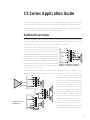
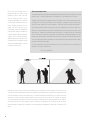
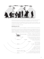
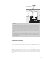
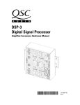
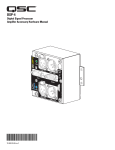
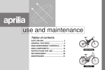
C O N T R A C T O R
A M P L I F I E R S
Application Guide
29
Table of Contents
Distributed line principles ................................................................................................... 3
Sidebar: Ohm’s Law ....................................................................................................................................... 4
Why 70 volts? ................................................................................................................................................. 4
Sidebar: Transforming voltages and impedances ........................................................................................ 5
“Natural” voltages ......................................................................................................................................... 5
Designing the distributed sound system...........................................................................6
Loudspeaker coverage and placement ......................................................................................................... 6
Sidebar: Reverberation and RT60 .................................................................................................................................................................................................. 7
Sidebar: The Inverse Square Law ................................................................................................................. 8
Determining power levels ............................................................................................................................. 9
Calculating total power requirements ....................................................................................................... 11
Fitting amplifier power ................................................................................................................................ 12
Using components with different line voltages ......................................................................................... 13
Sample applications & output configurations ............................................................... 14
Other design considerations ............................................................................................. 16
Speaker transformer saturation ................................................................................................................. 16
Sidebar: Installation tip ............................................................................................................................... 16
Speaker wire loss ........................................................................................................................................ 17
AC current consumption .............................................................................................................................. 19
Thermal losses (heat emissions) ................................................................................................................. 20
System design with CX Series amplifiers ......................................................................21
Features ........................................................................................................................................................ 22
The inner workings ............................................................................................................. 22
Exclusive CX features and accessories ......................................................................... 23
DataPort ....................................................................................................................................................... 23
Accessories .................................................................................................................................................. 23
IT-42 isolation transformer pack ................................................................................................................. 24
Crossover and filter modules ...................................................................................................................... 24
Front & rear panels ............................................................................................................. 25
Specifications ......................................................................................................................28
Address & Telephone Information ................................................................................... 30
1
©Copyright 1996, 1999 QSC Audio Products, Inc. All rights reserved.
QSControl is a trademark of QSC Audio Products, Inc.
“QSC” and the QSC logo are registered with the U.S. Patent and Trademark Office.
2
CX Series Application Guide
With the helpful advice and input from contractors and consultants around the world, engineers at QSC designed
the CX Series amplifiers to be a versatile and reliable foundation for high quality installed sound systems.
This applications guide will help you design your sound system properly and utilize your CX amplifier(s) effectively.
It starts with a tutorial on distributed (constant voltage) speaker systems.
Distributed line principles
The best way to power a system of numerous relatively low-powered loudspeakers from a single amplifier is
to use a distributed line, which combines the simplicity of connecting speakers in parallel across a pair of wires
with the versatile capability to individually tailor the power delivered each speaker.
Distributed lines, often called constant-voltage lines, are catego-
1.2W
suggests that the voltage on the line does not correlate to the audio
signal level. But in fact, there’s nothing constant about the voltage
on a “constant-voltage” line; the voltage on the distributed line is
indeed an audio signal and will modulate as the audio itself does.
2.5W
70V
16
5W
8
10W
4
COM
4.5V
8
rized by their maximum RMS voltage: 25-, 70-, 100-, 140-, 200-volt,
etc. The name “constant voltage” can be misleading because it
COM
If you connect a voltmeter across a 70-volt line, you will seldom
Example of a loudspeaker connected to a
actually measure 70 volts except on audio peaks. If the audio is distributed line through a transformer
muted, you will measure zero volts.
Distributed-line amplifiers are designed to produce maximum power at the line voltage. For example, a 70-volt
amplifier will produce its maximum power at 70 volts, regardless of whether it’s a 50-watt, 150-watt, or 7001.2W
watt model. What will differ from one power
70V
16
5W
8
10W
4
Amplifier
rating to another is the amount of current the amp
can put out, as you can determine by using Ohm’s
COM
0
8
2.5W
Law. (If you need to brush up on Ohm’s Law, see
the sidebar on the next page.) Thus, a 70-watt
A
COM
amp is designed to put out as much as 1 ampere
at 70 volts, while a 350-watt amp will be able to
2.5W
1W
8
10W
4
COM
COM
2W
Example of a 70 volt
distributed line
SPKR
COM
B
8
0.5W
16
5W
8
1.2W
C
produce up to 5 amperes at that voltage. Compare that to regular low-impedance amplifiers,
whose power ratings are directly related to the
maximum voltages the amps can put into 8, 4, or
2 ohms, so that a higher-powered amp has a
higher output voltage for a given load than a
lower-powered amp does. For instance, an amplifier rated at 100 watts into 8 ohms can put out
3
as much as 28.3 volts, as determined by Ohm’s Law, while an amp that
does 200 watts into 8 ohms can put out 40.0 volts.
Ohm’s Law
Nearly two centuries ago a German scientist named Georg Ohm
This is where the true concept of “constant voltage” comes in; it helps
simplify system design by converting one of the variables into a constant
value. But you can’t just connect typical 8-ohm speakers across a 70volt line because they’ll want to draw about 625 watts each. How then
do you plan and control the amount of power to each speaker when you
have a defined maximum line voltage? The answer: through transform-
discovered that the current through a load is directly proportional to the voltage across it, and also inversely proportional
to the resistance of the load. This relationship is called Ohm’s
Law, and the scientific community honored ohm by naming the
unit of resistance after him. In its basic form, Ohm’s Law is
expressed as the equation
ers. Each speaker has a transformer that converts the line voltage to
another value (almost always lower) to actually drive the speaker. Taps
on the transformer allow you to select the power level the speaker
receives when the line voltage reaches its maximum of 70 volts. It is
somewhat analogous to AC electrical service, in that you can plug a 100watt appliance and a 50-watt one into outlets carrying the same 120
VAC; you don’t have 120 volts for one and 85 volts for the other.
Regular low-impedance amplifiers are perfect for systems with one,
two, three, or four speakers per amp channel, with each speaker getting
the same amount of power. But if you need to power more speakers,
or provide different power levels to some or all of them, you would often
have to do some complicated series-parallel calculations and wiring.
E=I×R
where E is voltage (in volts), I is current (in amperes), and R is
resistance (in ohms).
You can also use Ohm’s Law to calculate the power in the load,
which is equal to voltage times current. The properties of
power, voltage, current, and resistance are all interrelated, so
if you know the value of
any two of them, you
can calculate the
other two. This
And even then if a speaker fails, is removed, or must be added, it would
alter the power distribution among the rest. A distributed line elimi-
Ohm’s
Law
“wheel” shows
how to solve for
nates the need for such calculations and considerations. It lets you
forget about impedances. And it also lets you substitute amplifier
any of the four
properties.
voltage
resistance
models as needed without having to re-calculate power distribution
among the loudspeakers. For example, if expanding a distributed
speaker system or increasing some power taps requires you to upgrade
a 150-watt 70-volt amplifier to a 200-watt model, you can do so without re-calculating or reconfiguring all the
other speaker taps, although you would have to match the gain of the new amp to that of the old one.
Why 70 volts?
If 70 volts seems like an odd number to become a de facto standard for distributed line voltage, how about 70.7 volts?
That’s the actual figure used in design of distributed lines, although it suggests a lot more precision that you
should hope to measure on an audio voltage. The number 70.7 came about for two reasons. First, as we’ve seen
already in this book, many loading and impedance calculations involve squaring the voltage. The approximate square
of 70.7 is 5000, which was easy to remember and work with in the days before pocket calculators. The second
reason is that versions of the National Electrical Code (NEC) before 1999 classify signal circuitry of 100 volts or higher
as Class 1, requiring a higher grade of wiring. Settling on 70.7 volts allowed a distributed line circuit to be deemed
a Class 2 circuit, with a safety margin of exactly 3 dB to allow for loading variations, audio peaks, etc.
Distributed line voltages other than 70 volts are common in some areas and applications. In Europe, 100-volt lines
are prevalent instead of 70 volts. And in the United States, 25-volt lines are common in public school buildings. In
applications where distributed lines have to run very long distances, 140- and 200-volt lines carry the audio power at
a high ratio of voltage to current (a high-impedance line, in other words) to minimize losses due to wire resistance.
4
current
power
Transforming voltages and impedances
Imagine driving a system of 100 8-ohm speakers at a low power (say, 8 watts each) with a single amplifier, like
you might need to do in an office building’s paging system. How would you do it? Connect them all in parallel,
perhaps with 00 AWG cable to wire them all together, and find a power amp that can do 800 watts into 0.08
ohms, which comes out to 8 volts and 100 amperes?
1A
8Ω
Spkr 1
8W
Spkr 2
1A
8W
That’s not practical, not the least because no such amplifier exists!
Or would you use a 70-volt amp with a rating of 800 watts or better, and put a transformer on each speaker to
provide the desired power level? Then the amp has to put out 70 volts at 11.4 amperes, for an equivalent load
of 6.13 ohms. That’s much more reasonable.
A speaker transformer steps the line voltage down to a lower level to drive the
speaker. In doing so, it also steps up the speaker impedance, so that the line itself
sees the speaker/
transformer combina-
613Ω
70v 8v
1A
8Ω
Spkr 1
8W
613Ω
70v 8v
1A
Spkr 2
8Ω
Sp
8W
tion as a relatively high
impedance.
Amp: 800 watts
@ 0.08Ω?
8v
100 A
Spkr 99
1A
Total load impedance ≈ 0.08Ω
For example, the
transformers in this
8W
Spkr 100
1A
8W
example have an
8.75:1 voltage step-down, converting 70 volts from the distributed line to 8
volts for the speaker. Into an 8-ohm speaker, that will produce 8 watts.
8W
The ratio of the impedance step-up is equal to the square of the voltage ratio
in the other direction. Therefore, the 8-ohm impedance of the speaker driver
800-watt
70V amp
will be multiplied by a factor of 76.56, resulting in the line seeing a theoretical
impedance of 613 ohms. (The actual figure will be somewhat less because
70v
11.4 A
of the transformer’s insertion loss.)
Spkr 99
Total load impedance ≈ 6.13Ω
The importance of this phenomenon is that the high impedances allow you
8W
Spkr 100
to connect many speakers—25, 50, 100, etc.—in parallel on the line, which
you would not be able to do with speakers alone in a practical way.
8W
“Natural” voltages
Some power amps designed for powering direct low-impedance speaker loads have power ratings that make
them suitable for driving distributed lines, too. An 8-ohm load draws 625 watts at 70.7 volts, so an amp rated
for 600 to 650 watts into 8 ohms is often termed a “natural” for driving a 70-volt line. This relationship works
for other line voltages, too, although they are rare for 100 volts and higher:
25V
70V
100V
140V
200V
75–80 watts @ 8Ω
600–650 watts @ 8Ω
1200–1300 watts @ 8Ω
2400–2600 watts @ 8Ω
4800–5200 watts @ 8Ω
150–160 watts @ 4Ω
1200–1300 watts @ 4Ω
2400–2600 watts @ 4Ω
4800–5200 watts @ 4Ω
9600–10400 watts @ 4Ω
300–320 watts @ 2Ω
2400–2600 watts @ 2Ω
4800–5200 watts @ 2Ω
5
Designing the distributed sound system
There are several main steps in designing a distributed sound system:
•
Determining loudspeaker coverage and placement
•
Determining power levels for each loudspeaker
•
Choosing the right amplifier
Loudspeaker coverage and placement
In placing loudspeakers in a distributed system, the goal is to provide coverage effectively but economically. An
effective coverage would be one where the sound from the loudspeakers is not only audible, but also intelligible,
wherever needed. An economical coverage would tend to be one that achieves the goal using the fewest
loudspeakers necessary.
A loudspeaker in an enclosed area produces two sound fields. The main one is the direct field—sound coming
directly “line-of-sight” from the loudspeaker. Primary and secondary reflections can also be considered part of
the direct sound field, as long as their delays are short enough to psychoacoustically reinforce the original sound.
The other is the diffuse field (sometimes called the reverberant field), which is sound that you might call “post
direct.” This diffuse field of reverberation is sound that has bounced around the room, reflecting off surfaces
such as floors, walls, tables, ceilings, etc., until it is absorbed by the air, other objects, and the room itself. The
diffuse field is comprised of multiple sound wave fronts traveling in different directions, each taking a slightly
Thus, to keep intelligibility high, you should maximize
the ratio of direct field to diffuse field. As the Inverse
Square Law dictates (see the sidebar on page 8), the
direct field sound falls off as the distance from the
loudspeaker increases. The diffuse field is also subject to the Inverse Square Law, but moving away from
one reflective surface often moves you towards
another; as a result, the intensity of the diffuse field
usually doesn’t vary significantly throughout a room.
The graph at right shows the direct, diffuse and
combined sound fields (direct and diffuse, summed)
of a single loudspeaker in a large, fairly reverberant
room. Closer to the speaker, the direct field is much
stronger than the diffuse field; intelligibility here will
be very good to excellent, but it will drop off as you
move further away. At the critical distance, DC, the
direct and diffuse fields are equal in intensity, and
beyond DC the diffuse field overpowers the direct. At
this position a person speaking clearly though the
sound system might be heard, but not clearly enough
6
Relative SPL (referenced to 1 meter from loudspeaker)
different length of time to arrive at the listener (or microphone). As a result, a common characteristic of the diffuse
field is “image smearing,” which reduces the intelligibility of the sound.
0.0
-5.0
-10.0
Dir
-15.0
-20.0
ec
ts
Dir
ect
ou
nd
+d
iffu
fie
ld
se
fiel
ds
Diffuse (reverberant) sound field
-25.0
-30.0
-35.0
1
10
20
30
40
Distance from loudspeaker, in meters
Critical distance, DC
Intensity of direct and diffuse sound fields in an enclosed space
Reverberation and RT60
to be understood: this is the “what did he/she
say?” syndrome. In this example, DC is approxi-
A common and useful measurement of a room’s reverberance is its reverberation
mately 15 meters.
time, or RT60. It is defined as the time it takes a sound in a space to decay 60 dB (or
one millionth of the acoustic power). The more reverberant the room, the longer the
Not all reverberation is detrimental. A controlled
RT60. Reverberation time is most precisely measured with special test gear such as
MLSSA or TEF equipment or the SMAART system.
In general, shorter values tend to be better for speech, while longer ones tend to
make music, particularly instrumental, sound fuller and more pleasing to the ear.
Here are typical targeted reverberation times for various types of venue:
Conference halls, meeting rooms, etc.
0.6–1.2 seconds
Cinemas
0.8–1.2 seconds
Live theater (including musical and variety shows)
1.0–1.4 seconds
School halls, multi-use rooms
1.0–1.5 seconds
Opera houses
1.0–1.6 seconds
Recital and chamber music halls
1.2–1.6 seconds
Concert halls (orchestral)
1.6–2.2 seconds
Organ and choral music
2.0–4.0 seconds
amount, either natural or added electronically,
can enhance the aesthetics of speech and, to a
greater extent, music. However, adding electronic reverb on a sound system designed for
mostly utilitarian purposes—e.g., paging or recorded background music—is very rare.
The less reverberant the room, the less intense
the diffuse sound field will be, and DC will be
greater. Conversely, increased reverberance of a
room will shorten DC and sharply reduce the
intelligible coverage area of the sound system.
Increasing the power to the loudspeaker is not a
remedy, because the increased direct field in turn
excites the diffuse field. The result is the relationship between direct and diffuse fields will stay
about the same. And to make matters worse, the
likelihood of feedback through an open microphone increases.
Solutions to maximizing sound system intelligibility in a difficult room include:
• controlling the reverberant nature of the room through acoustical treatment of reflective surfaces, and
architectural means.
• controlling coverage by using loudspeakers with directional qualities (Q) that will help keep sound on
the audience and off the walls and other surfaces.
Center
cluster
• using many low-powered loudspeakers close to the audience instead of one (or a few) centrally located
high-powered loudspeakers. This often also requires less total audio power and the
production of less acoustic energy, which further helps reduce the
diffuse field.
The last approach is often best accomplished
through a distributed line speaker system. A
distributed line might also be useful for cov-
Under-balcony fill
ering problematic areas in a room, such as the
under-balcony seating in a theater served by
a center cluster; a line of small speakers under
the balcony, as illustrated at left, could help
provide good sound to that portion of the
audience.
7
One of the most common uses of
distributed lines is to power ceiling
speakers in office, retail, and commercial buildings. With ceilingmounted loudspeakers, one common
rule of thumb is to make the center-tocenter distance between them no
greater than twice the floor-to-ceiling distance. Used with loudspeakers
that have a 90° angle of coverage, this
is often suitable for background music
systems, but for paging and public
address applications it tends to have
somewhat erratic coverage at normal
sitting and standing positions, as the
illustration below shows.
The Inverse Square Law
The Inverse Square Law says that as a sound wave travels away from its source, its intensity, or sound
pressure level, is inversely proportional to the square of D, the distance from its source.
Therefore, the intensity of a sound wave when D = 2 meters is only 1/4 of what it was at 1 meter;
at 3 meters, it’ll be 1/9, and at 4 meters, 1/16. In decibels, 1/4 power is equal to -6 dB; that’s
why the Inverse Square Law is often stated as ”-6 dB every time you double the distance.”
Sound waves travel outward from a source, such as a loudspeaker or a person’s mouth, in all
directions. The sound might be stronger in some directions than others, but it all travels at the
same velocity. Therefore, sound waves tend to be spherical, or partially spherical, around the
source. The area of a sphere is proportional to the square of its radius (analogous to D); the
energy of the sound wave is distributed over this area. If you think of sound intensity as force/
area, such as dynes per square centimeter, you can see how the increasing spherical area causes
intensity to diminish accordingly.
For those unafraid of a little math, the difference in SPL at one distance, D1, and a reference
distance, D2, is equal in decibels to
dB = -10 × log(D1/D2)
A better technique is to space the ceiling speakers at twice the distance from the listeners’ ears to the ceiling.
This requires more loudspeakers spaced closer together but provides greater intelligibility through better, more
uniform coverage at realistic listening positions. In a room where people are standing, you’ll need a little closer
spacing than if they are sitting, simply because their ears are closer to the ceiling. For example, a company
lunchroom needs a sound system; it has a ceiling height of 2.9 meters (9.5 ft), and you determine the height of
an average listener’s ear, when seated, is about 1.1 meter (3.5 ft) above the floor. That puts the ceiling-to-ear
distance at about 1.8 meters (6 ft); therefore, you should space the loudspeakers no more than 3.6 meters (12 ft)
apart.
8
Better, more uniform coverage will result from spacing the loudspeakers at 1.5 times the ceiling-to-ear distance.
In the lunchroom example, this would require spacing the loudspeakers about 2.7 meters (9 ft) apart.
Some manufacturers now offer ceiling loudspeakers with dispersion angles much wider than 90 degrees. These
allow greater spacing between speakers, and consequently it takes fewer of them to cover the same area,
although each one will require more power.
Determining power levels
After you’ve determined where to place the loudspeakers, you need to calculate the power each one requires.
Background music will require an SPL at least 10 dB above the ambient noise. For good paging intelligibility, you’ll
need an SPL approximately 15 dB higher than the ambient noise; 25 dB above ambient will yield excellent
intelligibility. If the installation is in an existing facility already in use, use an SPL meter, set for slow response, to
measure the A-weighted ambient noise at several typical listening positions. Try to take this measurement at the
1 watt in
noisiest time—in a factory, when the machines
sensitivity = 92 dB, 1 watt @ 1 m
turning the system level down for quieter moments, but it’s difficult to get more level than
D = 1 meter
92 dB SPL
are running; in a restaurant, when it’s full of
patrons, etc. You can always make provisions for
D = 2 meters
you planned for, without a major recalculation of equipment needs.
Next, measure the distance, D, in meters
D = 3 meters
86 dB SPL
D = 4 meters
from the loudspeaker
to the listeners’ ears.
Use D along with the
loudspeaker’s sensitivity
82.5 dB SPL
SPL(@ 1 watt) = sensitivity – (20logD)
80 dB SPL
rating (typically expressed as
“n dB @ 1 watt, 1 meter,” which
means n dB of SPL with 1 watt input,
measured at a distance of 1 meter) to determine how much power the loudspeaker needs to get
9
from the distributed line. Use the formula
dB = 20×logD
or the Inverse Square guide below to convert distance-related attenuation to dB; you’ll need to add this figure
to the desired SPL and then subtract the sensitivity rating to determine how much more or less than 1 watt the
loudspeaker requires.
Distance from speaker
Power increase in dB; referenced to loudspeaker
sensitivity rating (1 watt @ 1 meter)
Calculating the necessary power is simple addition and subtraction if you use dBW, a decibel reference to watts
in which 0 dBW = 1 watt. This is useful because the sensitivity spec already uses a reference of 1 watt. Then
you can use the formula
Power (in dBW)
= (desired SPL) + (distance attenuation) – (speaker sensitivity)
20.0
To convert dBW to watts, use the graph at right or the formula
Power (watts)
dBW (ref 1 watt)
18.0
= 10(dBW/10)
16.0
14.0
12.0
10.0
8.0
6.0
4.0
2.0
0.1
0.2
0.5
0.0
-2.0
-4.0
-6.0
-8.0
-10.0
10
Power (Watts)
1
2
5
10
20
50
100
97.2 dB
1.8 me
ters
2.1 watts (3.2 dBW) in
(sensitivity = 94 dB @ 1W, 1 m)
EXIT
92 dB
Ambient noise
= 67 dBA
EXAMPLE
A loudspeaker (sensitivity: 94 dB @ 1W, 1 meter) in a busy office covers an area with an ambient noise
level of 67 dBA, measured at a seated person’s ear position at the desks. The client wants superb
intelligibility, so your goal is to provide an SPL of 92 dB (25 dB above ambient SPL) to the intended
listeners, the office workers. The ceiling-mounted speaker is about 6 feet, or 1.8 meters, from the
workers’ ears. The attenuation for D of 1.8 meters is 5.2 dB; this means that the loudspeaker would
have to produce 97.2 dB (92 plus 5.2) at a distance of 1 meter to achieve 92 dB at a distance of 1.8
meters.
The loudspeaker will require a power level of 3.2 dBW (97.2 minus 94); this works out to 2.1 watts.
The speaker transformer taps are 0.5, 1, 2, 4, and 8 watts; the closest choice would be the 2-watt tap,
an almost exact match.
Calculating total power requirements
After you’ve determined the power taps for each loudspeaker transformer on the distributed line, add them up.
The sum will be a start toward calculating the amplifier power requirements. If you have 16 loudspeakers tapped
at 2 watts, seven at 1 watt, and eight at 10 watts, the total audio power the loudspeakers want is 119 watts.
Thanks to a transformer phenomenon called insertion loss, though, your amplifier actually needs to provide more
power than the loudspeakers will get. High-quality speaker transformers typically have an insertion loss of about
1 dB or less, meaning that it takes as much as 1.25 watt going into the transformer to put 1 watt into the
loudspeaker. A lower-quality transformer may have a loss of 2 dB, which requires approximately 1.6 watts for
every watt that the loudspeaker receives. Poor-quality transformers may have even higher losses, but they will
probably degrade the system’s audio performance severely even if you allow extra amplifier power to overcome
the losses.
11
To compensate for the insertion loss, add a corresponding percentage to the sum of the transformer power taps.
For transformers with a 1 dB loss, add about 25%; in the example above, that would increase 119 watts up to
149 watts. To compensate for lesser-quality trtansformers with insertion losses of 1.5 dB and 2 dB, add 40%
and 58%, respectively, to their individual power tap figures. Therefore, even with medium-quality speaker
transformers, it could easily take up to 188 watts to provide 119 watts to the speakers! The sum of the power
taps, corrected for insertion loss, is the distributed line’s total power demand.
Fitting amplifier power
Choose an amplifier model whose power rating meets or exceeds the distributed line’s total power demand.
If it is a 70-volt line, use the per-channel power ratings of the CX-V direct 70-volt models (CX 302V, CX 602V,
or CX 1202V). Hint: It is a good engineering practice to add up to 25% to the line power demand figure, to allow
a margin both for dynamic audio headroom and for some future adjustments to the system—an added speaker
or two, a few transformer tap changes, etc.
Use the CX302 with the IT-42 isolation transformer accessory for these applications:
• for 25-volt lines up to 300 watts
• for 70-volt lines up to 400 watts that require isolation
• for 100-volt lines up to 400 watts
• for a 140-volt line up to 800 watts (with the amp in bridged mono mode)
• for a 200-volt line up to 800 watts (with the amp in bridged mono mode)
Question: Like other QSC amps, the CX models carry two types of power ratings, EIA and FTC. The EIA ratings
are specified at 1 kHz, at no more than 1% THD. The FTC ratings are more stringent, measured over a wide
specified frequency range with THD not exceeding 0.05%. Which should you use?
Answer: Use the FTC spec for sound systems with a high duty cycle, i.e., operating at or near full power for
extended periods of time. Some foreground music systems fall into this category. Use the EIA 1 kHz spec for
systems with a light to moderate duty cycle, such as paging and announcing systems or combination background
music/paging systems.
12
Using components with different line voltages
Sometimes it may be practical to use a transformer or loudspeaker/transformer combination with a different
voltage system from what it was originally intended. For example, a 70-volt transformer could be used in a 25-volt
system, although you would have to derate the power taps similarly. But never use a transformer with a higher
voltage than what it is designed for; i.e., you couldn’t use that same transformer on a 100- or 140-volt line.
To properly derate the transformer tap power levels, use the chart
at left. Locate the column with the voltage the transformer is
rated for, then locate the row with the system voltage you want
to use it in. The table will indicate the dB reduction to use with
the derating chart below.
Derated Value of Power Tap, in watts
100
10
1
0.1
B
-3 d
B
d
-6
B
-9 d
dB
-12
dB
-15
dB
-18
0.01
0.001
0.1
1
10
Original Value of Power Tap, in watts
100
EXAMPLE
You have a 70-volt transformer with taps labeled 1, 2, 4, and 8 watts. What power points will those
taps provide on a 25-volt line?
The table shows that 25 volts is 9 dB less than 70 volts. The chart confirms that the taps will provide
0.125, 0.25, 0.5, and 1 watt, respectively.
13
Sample applications & output
configurations
70V
subwoofers
75W
20W
20W
75W
20W
20W
75W
20W
20W
75W
20W
20W
20W
20W
20W
20W
70V
full-range
speakers
subwoofer x-over
Load
Charge
= 300W
Last
Carga
Ch. 1
CX 602V
Ch. 2
Load
Charge
= 240W
Last
Carga
A CD megastore 70V system, with subwoofers
Ch. 1
> 2Ω
> 8Ω
> 4Ω
Ch. 2
> 2Ω
> 8Ω
> 4Ω
CX 302, CX 502,
CX 702, & CX 902
CX 602V
CX 1202V
Minimum loading, stereo & parallel modes
25W
25W
2W
2W
40W
55W
20W
20W
5W
75W
5W
5W
5W
5W
5W
10W
5W
5W
10W
5W
1.2W
Load
Charge
= 230W
Last
Carga
Ch. 1
Ch. 1
CX 302V
> 4Ω
> 16Ω
> 8Ω
Ch. 2
Ch. 2
CX 302, CX 502,
CX 702, & CX 902
Minimum loading, bridged mono mode
14
CX 602V
CX 1202V
Load
Charge
= 100.2W
Last
Carga
A 2-zone 70V system
8Ω
15W
Center cluster
15W
20W
20W
25W
5W
10W
20W
25W
5W
Mens room
8Ω
10W
Dressing room A
Rehearsal room
15W
Ladies room
10W
20W
5W
10W
20W
10W
5W
10W
10W
20W
5W
20W
25W
w/ L-pad
house mix
20W
Ch. 1
parallel
input
mode
CX 1202V
Theater
Dressing room B manager’s office
Ch. 2
Load
Charge
= 425W
Last
Carga
Lobby/box office/lounge area
25W
Green room
Carpentry shop/
prop room
20W
Control room
5W
Corridors
House system for a small theater
15
Other design considerations
+1
1
LF OFF
2
Speaker transformer saturation
3
0 dB
-1
5
6
-2
7
Ch. 1
Ch. 2
4
8
LF OFF
-3
9
10
Speaker transformers tend to be fairly small and can vary widely in quality. Many are
thus prone to core saturation at low frequencies, which occurs when the magnetic
-4
field induced in the transformer’s iron core by the audio signal waveform reaches the
limit the core can handle. Even if the instantaneous current increases in the primary
-5
-6
20 Hz 30 40 50 60 80 100
2
9
1
2
3
1 kHz
5
6
7
-2
8
9
LF ON
-3
10
-4
-5
-6
20 Hz 30 40 50 60 80 100
1
2
3
4
-1
5
6
-2
7
Ch. 1
Ch. 2
+1
LF ON
75 HZ 0 dB
8
9
75 HZ
LF ON
-3
10
-4
-5
-6
20 Hz 30 40 50 60 80 100
Once the sound system is installed and operational, turn the amplifier off and take an impedance measurement
across the distributed line at the amplifier output, using an audio impedance meter (not an ohmmeter). Record
the measurement for later use. If you ever have to make a service call on the system, measure the impedance
again and see how it compares to the recorded figure; it’s a quick and easy way to see if anything in the
distributed line system has been changed. Likewise, measure and record the impedance anytime you’ve
changed a transformer tap,
18.5
16
300 400 500
-1
INSTALLATION TIP:
Amp
200
0 dB
4
33 HZ
high-pass filters; the “V” models offer 12 dB-per-octave rolloffs at 50 or 75 Hz, while
the “non-V” models offer 33 or 75 Hz. The input filters can also be switched off, but
Z meter
1 kHz
+1
LF ON
to prevent saturation is to filter out the frequencies most likely to cause it without
adversely affecting the audio quality. The CX models have user-selectable built-in
corresponding high-pass filtering in the audio signal path before the amplifier.
300 400 500
10
-6
20 Hz 30 40 50 60 80 100
Ch. 1
Ch. 2
quality speaker transformers. However, if any speaker transformers on the line do
not have low-frequency responses at least as low as 75 Hz, you must insert
200
-5
33 HZ
we recommend that only if there is adequate filtering in the signal path before the
amp. The amplifiers’ filters are adequate saturation prevention for virtually all good-
1 kHz
-3
-4
spike travels along the line back to the amplifier, which has to absorb it. Interestingly,
this phenomenon is much more likely to happen on a lightly loaded line than on a
Besides using larger, more expensive transformers of higher quality, an effective way
300 400 500
8
LF ON
the power amplifier driving the line: as the transformers go out of saturation, their
magnetic fields collapse and induce a large voltage spike across the line. That voltage
heavily loaded one.
200
-2
7
50 HZ
6
Saturation causes audible distortion, but in rare yet extreme cases it can also damage
0 dB
-1
5
Ch. 1
Ch. 2
1 kHz
4
so they are of much less concern.
LF ON
3
50 HZ
300 400 500
+1
1
windings, the magnetic flux in the core cannot, so it “clips,” in a way. High frequencies
generally reverse the direction of the magnetic flux well before saturation occurs,
200
added or removed a loudspeaker, or made any other
adjustment to anything on
the distributed line.
Speaker wire loss
A wire’s resistance is inversely proportional to the cross-sectional area of its conductor, but even the highestquality copper wire has some amount of resistance to electrical current flow. Therefore, to minimize the power
lost to speaker cable resistance, you should use the largest stranded (always stranded) copper wire that is
practical for the job. This is especially important with direct low-impedance speaker connections; e.g., a halfohm wire resistance would not affect a lightly-loaded 100-volt line noticeably, but it would reduce the amount of
power going to a 2-ohm load by 36%, a 1.9 dB drop. It would also reduce the damping factor to no better than 4.
If an amplifier could drive a speaker load through theoretical zero-resistance wire, no power would be lost in
the speaker cables. In the charts below we’ll compare the power delivered through real-world speaker cables
with the theoretical zero-resistance ideal and express it as a ratio called the power transfer coefficient. It is
determined by the formula
POWER TRANSFER COEFFICIENT = [RLOAD/(RWIRE + RLOAD)]2
Let’s say you have an 8-ohm speaker load. With that imaginary zero-resistance wire, all the power would be
delivered to the load, so the power transfer coefficient would be 1. If you then substituted wire with 0.2 ohm
of resistance, the load would only get 95.2% of the power it got with the zero-ohm wire, so the power transfer
coefficient would be 0.952 (a loss of 0.2 dB, by the way).
17
AC current consumption
A major objective in the design of the CX Series amplifiers—even the higher-powered models—is to permit
their operation from readily available, standard AC power sources. Actual current consumption will depend on
the amp model, the power level it is operating at, and the load impedances.
“Normal conditions” in power amplifier ratings means operating with a random program source (pink noise), at
an average power level equal to one-eighth of maximum power. This is recognized by most of the world’s safety
agencies as approximating the loudest level you can play music through an amplifier and still keep the incidence
of clipping to a reasonable and inaudible minimum. An amplifier’s peak current draw at full output power into
2 ohms is several times what the “normal” draw is, but its various protection circuits will prevent this condition
from lasting more than a minute or two.
When you plan the AC power hookups for your amplifiers, use this table to predict the current requirements per
amplifier. You can use the one-eighth power figures to predict the normal continuous current draw, then add
a safety margin to allow for occasional crescendos.
CX302
CX502
Load
Idle
8Ω + 8Ω
1/8 Power 1/3 Power Full Power
(pink noise)
(pink noise)
(sine)
0.8 A
3.8 A
5.4 A
8.4 A
4Ω + 4Ω
0.8 A
6.0 A
8.9 A
14 A
2Ω + 2Ω
0.8 A
9.6 A
14.3 A
23 A
8Ω + 8Ω
0.9 A
5.6 A
8.0 A
12.5 A
4Ω + 4Ω
0.9 A
9.0 A
13.3 A
21 A
2Ω + 2Ω
0.9 A
14 A
21 A
34 A
8Ω + 8Ω
0.9 A
5.0 A
8.4 A
15.8 A
4Ω + 4Ω
0.9 A
7.9 A
13.5 A
26 A
2Ω + 2Ω
0.9 A
11.8 A
22 A
42 A
8Ω + 8Ω
0.9 A
6.0 A
11 A
20 A
4Ω + 4Ω
0.9 A
9.5 A
17 A
33 A
2Ω + 2Ω
0.9 A
14 A
27 A
50 A
8Ω + 8Ω
0.9 A
7.6 A
13.1 A
25 A
4Ω + 4Ω
0.9 A
11.6 A
20 A
39 A
2Ω + 2Ω
0.9 A
16.6 A
CX302V 70V + 70V
0.8 A
5.7 A
8A
16 A
CX602V 70V + 70V
0.9 A
8.7 A
13 A
21 A
CX1202V 70V + 70V
0.9 A
12 A
19 A
39 A
CX702
CX902
CX 1102
POWER CONSUMPTION NOTES
• “Idle” represents amplifier operation with signal levels 40 dB below full
power or lower. Power consumption in standby mode is less than 5 watts.
• 1/8 power with pink noise represents typical program with occasional
clipping, or the approximate highest output level before clipping becomes
audible. Use this rating for most operation.
• 1/3 power with pink noise represents severe program with heavy clipping.
This is an absolute worst case scenario, and approximates music played at
absolute maximum level just short of total obliteration by clipping. This might
be encountered in dance clubs and other scenarios where impact is more
important than fidelity of sound. To avoid overheating, do not use load
impedances lower than 4 ohms per channel (non-”V” models) or lines loaded
at higher than 50% of the amp rating (“V” models).
• Full power measurements are with a continuous sine wave at 1% clipping.
This would be encountered only in bench testing or driving a continuous
signal such as a siren. In normal operation, full-power peaks are usually brief
and rarely more than a 25%duty cycle. Continuous full-power operation is
generally possible at the lightest loading (8 ohms per channel for non-”V”
models; 50% loading for “V” models). This rating shows peak AC consumption and performance in unusual applications.
• Thermal or overcurrent cutback limits duration of full-power operation at
heaviest load (2Ω or 100% load) after several seconds, and at half load (4Ω
or 50% load) after several minutes.
19
Thermal losses (heat emissions)
Essentially, a power amplifier draws electrical energy from the AC mains, converts it to DC, and then converts
it again into an analog of the input signal to power the loudspeakers. Power that enters the amplifier through
the AC cord, less that which exits through the speaker outputs, is lost and turns into heat, called thermal loss.
The amplifier must remove the heat to the outside surrounding space to prevent overheating. The amount of
heat loss will depend on the amp model, the power level at which it is operated, and its load impedances.
The table of thermal loss specifications below will allow you to predict the heat produced by an amplifier system
under various conditions and then specify adequate room cooling (e.g., air conditioning) to compensate. Use oneeighth power (the highlighted column) for normal, continuous usage. CX Series amplifiers are fan cooled, with
rear-to-front air flow to avoid heat buildup in the equipment rack. They are designed to produce continuous
1/8 average power or better into the heaviest loads shown, in ambient temperatures of 35º C (95º F).
Idle
CX 302
CX 502
CX 702
CX 902
CX 1102
1/8 Power (pink noise)
1/3 Power (pink noise)
Full Power (sine)
Load
BTU/hr
kcal/hr
BTU/hr
kcal/hr
BTU/hr
kcal/hr
BTU/hr
kcal/hr
8Ω + 8Ω
200
50
565
145
720
180
715
180
4Ω + 4Ω
200
50
995
250
1245
315
1295
325
2Ω + 2Ω
200
50
1740
440
2255
570
2425
610
8Ω + 8Ω
165
40
910
230
1130
285
1090
275
4Ω + 4Ω
165
40
1570
395
1945
490
1875
475
2Ω + 2Ω
165
40
2560
645
3470
875
3585
905
8Ω + 8Ω
200
50
790
200
1080
275
1245
315
4Ω + 4Ω
200
50
1310
330
1910
480
2320
585
2Ω + 2Ω
200
50
2255
570
3190
805
4610
1160
8Ω + 8Ω
220
55
900
225
1415
355
1705
430
4Ω + 4Ω
220
55
1525
385
2560
645
3070
775
2Ω + 2Ω
220
55
2305
580
4265
1075
5835
1470
8Ω + 8Ω
225
57
1195
300
1760
445
2050
515
4Ω + 4Ω
225
57
2135
540
2335
590
3755
945
1000
2Ω + 2Ω
225
57
3975
CX 302V 70V + 70V
200
50
1125
285
1295
325
1080
270
CX 602V 70V + 70V
165
40
1785
450
2260
570
2055
520
CX 1202V 70V + 70V
200
50
2175
550
2605
655
4230
1065
THERMAL LOSS NOTES
• “Idle” represents amplifier operation with signal levels 40 dB below full power or lower. Thermal losses in standby mode are less than
17 Btu/hr (4.3 kcal/hr).
• 1/8 power with pink noise represents typical program with occasional clipping, or the approximate highest output level before
clipping becomes audible. Use this rating for most operation.
• 1/3 power with pink noise represents severe program with heavy clipping. This is an absolute worst case scenario, and approximates
music played at absolute maximum level just short of total obliteration by clipping. This might be encountered in dance clubs and
other scenarios where impact is more important than fidelity of sound. To avoid overheating, do not use load impedances lower than
4 ohms per channel (non-”V” models) or lines loaded at higher than 50% of the amp rating (“V” models).
• Full power measurements are with a continuous sine wave at 1% clipping. This would be encountered only in bench testing or driving
a continuous signal such as a siren. In normal operation, full-power peaks are usually brief and rarely more than a 25%duty cycle.
Continuous full-power operation is generally possible at the lightest loading (8 ohms per channel for non-”V” models; 50% loading
for “V” models). This rating shows peak AC consumption and performance in unusual applications.
• Thermal or overcurrent cutback limits duration of full-power operation at heaviest load (2Ω or 100% load) after several seconds, and
at half load (4Ω or 50% load) after several minutes.
20
Thermal losses (heat emissions)
Essentially, a power amplifier draws electrical energy from the AC mains, converts it to DC, and then converts
it again into an analog of the input signal to power the loudspeakers. Power that enters the amplifier through
the AC cord, less that which exits through the speaker outputs, is lost and turns into heat, called thermal loss.
The amplifier must remove the heat to the outside surrounding space to prevent overheating. The amount of
heat loss will depend on the amp model, the power level at which it is operated, and its load impedances.
The table of thermal loss specifications below will allow you to predict the heat produced by an amplifier system
under various conditions and then specify adequate room cooling (e.g., air conditioning) to compensate. Use oneeighth power (the highlighted column) for normal, continuous usage. CX Series amplifiers are fan cooled, with
rear-to-front air flow to avoid heat buildup in the equipment rack. They are designed to produce continuous 1/
8 average power or better into the heaviest loads shown, in ambient temperatures of 35º C (95º F).
Idle
CX 302
CX 502
CX 702
CX 902
CX 1102
1/8 Power (pink noise)
1/3 Power (pink noise)
Full Power (sine)
Load
BTU/hr
kcal/hr
BTU/hr
kcal/hr
BTU/hr
kcal/hr
BTU/hr
kcal/hr
8Ω + 8Ω
200
50
565
145
720
180
715
180
4Ω + 4Ω
200
50
995
250
1245
315
1295
325
2Ω + 2Ω
200
50
1740
440
2255
570
2425
610
8Ω + 8Ω
165
40
910
230
1130
285
1090
275
4Ω + 4Ω
165
40
1570
395
1945
490
1875
475
2Ω + 2Ω
165
40
2560
645
3470
875
3585
905
8Ω + 8Ω
200
50
790
200
1080
275
1245
315
4Ω + 4Ω
200
50
1310
330
1910
480
2320
585
2Ω + 2Ω
200
50
2255
570
3190
805
4610
1160
8Ω + 8Ω
220
55
900
225
1415
355
1705
430
4Ω + 4Ω
220
55
1525
385
2560
645
3070
775
2Ω + 2Ω
220
55
2305
580
4265
1075
5835
1470
8Ω + 8Ω
225
57
1195
300
1760
445
2050
515
4Ω + 4Ω
225
57
2135
540
2335
590
3755
945
1000
2Ω + 2Ω
225
57
3975
CX 302V 70V + 70V
200
50
1125
285
1295
325
1080
270
CX 602V 70V + 70V
165
40
1785
450
2260
570
2055
520
CX 1202V 70V + 70V
200
50
2175
550
2605
655
4230
1065
THERMAL LOSS NOTES
• “Idle” represents amplifier operation with signal levels 40 dB below full power or lower. Thermal losses in standby mode are less than
17 Btu/hr (4.3 kcal/hr).
• 1/8 power with pink noise represents typical program with occasional clipping, or the approximate highest output level before
clipping becomes audible. Use this rating for most operation.
• 1/3 power with pink noise represents severe program with heavy clipping. This is an absolute worst case scenario, and approximates
music played at absolute maximum level just short of total obliteration by clipping. This might be encountered in dance clubs and
other scenarios where impact is more important than fidelity of sound. To avoid overheating, do not use load impedances lower than
4 ohms per channel (non-”V” models) or lines loaded at higher than 50% of the amp rating (“V” models).
• Full power measurements are with a continuous sine wave at 1% clipping. This would be encountered only in bench testing or driving
a continuous signal such as a siren. In normal operation, full-power peaks are usually brief and rarely more than a 25%duty cycle.
Continuous full-power operation is generally possible at the lightest loading (8 ohms per channel for non-”V” models; 50% loading
for “V” models). This rating shows peak AC consumption and performance in unusual applications.
• Thermal or overcurrent cutback limits duration of full-power operation at heaviest load (2Ω or 100% load) after several seconds, and
at half load (4Ω or 50% load) after several minutes.
20
System design with CX Series amplifiers
CX302
CX302
Left: a CX amplifier without its security cover installed
Right: a CX amplifier with its security cover installed
Model
Power, 8Ω/ch
Power, 4Ω/ch
Power, 2Ω/ch
20 Hz–20 kHz, 0.03% THD
20 Hz–20 kHz, 0.05% THD
1 kHz, 1% THD
CX 302
200 W
325 W
600 W
CX 502
300 W
500 W
800 W
CX 702
425 W
700 W
1200 W
CX 902
550 W
900 W
1500 W
CX 1102
700 W
1100 W
1700 W
Power @ 70V
Power @ 70V
20 Hz–20 kHz, 0.05% THD
1 kHz, 1% THD
CX 302V
200 W
300 W
CX 602V
400 W
600 W
CX 1202V
800 W
1200 W
Model
14.0"
13.85"
13.6"
13.48"
13.35"
355.6 mm
351.8 mm
345.4 mm
342.3 mm
339.1 mm
1.5"
38.1 mm
3.00"
76.2 mm
Specially designed for contractor and installed sound applications, the new CX Series amplifiers feature
PowerWave™ switching supply technology for better regulation and to eliminate hum. A new-generation direct
metal-mounted output section yields even lower distortion and higher current capacity, providing studio-quality
performance with touring-quality reliability and lightweight in a strong, compact chassis.
The CX Series comprises eight 2-channel, 2 RU models. Five are low-impedance amplifiers, designed to drive
loads of 8, 4, or 2 ohms per channel: CX 302, CX 502, CX 702, CX 902, and CX 1102. Into 8 and 4 ohms per channel,
they are suitable for full-power operation even at full duty cycle. Into 2 ohms per channel, they are suitable for
operation at full power at slightly reduced duty cycle.
Three models, designated by the letter “V” in the model number, are designed to drive 70-volt distributed lines
directly, without output transformers: CX 302V, CX 602V, and CX 1202V. They can be bridged to drive 140-volt
lines in mono. For critical operation or full duty cycle operations, the amps can drive line loads equivalent to the
20 Hz–20 kHz power ratings.
The “V” models can also drive low-impedance loads. See the power specs in the back of this manual for
appropriate ratings.
Aside from the types of speaker systems they are designed to drive, some features and setup procedures differ
between the low-impedance and “V” models.
21
Features
• Barrier strip output connectors
• Direct transformerless 70-volt outputs (“V” models)
• Zero inrush current—won’t trip circuit breakers at turn-on and avoids need for sequential power-up
• DataPort for use with QSControl and amplifier accessories
• Independent, user-defeatable clip limiters
• Fully selectable low-frequency filtering; choice of 33 or 75 Hz roll-off or 50 or 75 Hz roll-off (“V” models)
• Stereo (dual-channel), parallel-input, or bridged mono operating modes
• Balanced inputs: XLR and “Euro-style” detachable terminal blocks
• Recessed, detented gain controls with security cover
• Front panel LED indicators for power, signal, -20 and -10 dB, clip/protect, parallel inputs, and bridged mono mode
• QSC’s exclusive high-performance PowerWave switching technology power supply
• Optional isolated output transformer pack IT-42 available for driving 2-channel 25-, 70-, and 100-volt lines, or 50, 140, and 200-volt
lines in bridged mono (CX 302 only).
The inner workings
An impressive amount of technology is packed “under the hood” of a CX Series amplifier. Thousands of watts
of power flow inches away from state-of-the-art low noise inputs. Precise circuit layout and thorough protection
assure that all of this activity occurs smoothly and safely. So, what actually happens when you turn on the power
switch?
Soft Start Sequence. The first task is to charge the primary energy reservoir without drawing a large surge
current. A special inrush limiter allows just enough current to charge the energy bank in three seconds.
Meanwhile, a low-power switching supply provides power to start up the main supply. After three seconds, a
relay bypasses the inrush limiting and full power operation is enabled. The audio circuitry
mutes for one second to eliminate start-up thumps. When the red CLIP lights go out, the
amplifier is ready for action.
EMI Filter
PowerWave™ Technology. High current switching devices draw over 10,000 watts of
peak power from the main energy reservoir, which is replenished directly from the AC line
Inrush Limiting
for maximum stiffness. Conventional amplifiers must isolate the energy bank with a large
AC transformer, which weakens the flow of current, allows greater sag under load, and
produces hum. The PowerWave supply performs voltage conversion at a very high
frequency, allowing better coupling through a much smaller isolation transformer.
High Performance Audio. High speed power transistors convert this DC power into the
full range audio output which drives the speakers. High-current design and special dualsense output feedback corrects errors on both sides of the speaker terminals, improving
damping and control of speaker motion. The power devices are directly mounted to isolated
heat sinks, which form a short, wide air tunnel in front of the fan for optimum cooling.
Control
Power
Main Energy Bank
PWM
Control
PowerWave Switching
Transformer
A thermal sensor embedded in each channel’s heat sink monitors the temperature and
controls fan speed, thermal shutdown, and bias control, assuring maximum audio clarity
at all temperatures and signal levels. A circuit monitors transistor dissipation and triggers
protective cutback only when actually needed.
22
DC Supply for
Amplifier
Balanced
In
Filters
The output circuitry is actively clamped during clipping for smooth and very
fast recovery. The clamp also feeds a proportional clip limiter, which actually
Gain
senses the depth of clipping and responds accordingly.
The balanced inputs use premium 0.1% precision resistors for very high
noise rejection. The precision components used in the input filters and all
other circuitry ensure accurate performance.
Fan
DC Supply
Temperature
Sense
Clip
Limiting
Power
Control
DC
Blocking
Muting
Shutdown. The amplifier mutes as soon as power is shut off, preventing
turn-off noises. Serious faults trigger a shutdown of the power supply; the
+ Out
Output
high switching frequency cuts off power within microseconds to limit
damage.
– Out
DC Fault Monitor
Display
Exclusive CX features and accessories
15
14
13
12
11
10
9
8
7
6
5
4
3
2
1
DataPort
The amplifier features a DataPort, which connects to a QSControl MultiSignal Processor or other QSC accessories
via the HD-15 connector.
QSControl is a QSC-exclusive system for remotely controlling and monitoring amplifiers and other equipment
via an Ethernet-based data network and a personal computer. The operating software is easily customized using
Microsoft Visual Basic.
DataPort pin identification
Remote on/off using the DataPort
Even if you don’t use QSControl or an accessory with the amplifier, you can use the DataPort to remotely switch
To DataPort
Pin 2
To DataPort
Pin 2
To DataPort
Pin 2
one or more amplifiers on and off without having to switch AC currents. Shorting pin 2 of the DataPort to chassis
ground places the power supply in standby, shutting off the amplifier circuitry. Removing the short allows the
power supply to start up again, and the amplifier goes through its startup sequence. You can connect together
pin 2 of several CX amplifiers in the same rack and switch this connection to chassis ground to use as
Additional
amplifiers
(when applicable)
a remote on/off. There is no surge of inrush current when turning on a CX amp, so there is no danger
of tripping circuit breakers, and no need for sequential turn-on.
To DataPort
Pin 2
open = operate
closed = standby
(Amp chassis)
Remote on/off switching through the DataPort
23
Accessories
IT-42 isolation transformer pack
For applications requiring isolated 25-, 70-, or 100-volt outputs, the IT-42 (pictured at right), a unique
transformer “backpack” accessory, allows the CX 302 to deliver up to 400 watts per channel or zone
(300 watts on 25-volt lines). In bridged mono mode, it can be used to drive a single 140- or 200volt line loaded at up to 800 watts. The IT-42 mounts to the back of the amplifier, but it doesn’t
interfere with cooling airflow or inhibit access to input and output connectors or to the amp’s
configuration switches.
100V
Ch. 1 + out
70V
The IT-42 is available from your QSC CX dealer or distributor or from QSC’s Technical Services
department (phone: 1-800-QSC AUDIO (toll-free in USA only) or 1+ (714) 957-7150; e-mail:
Ch. 1 - out
[email protected]).
COM
For highest value and sound quality in music-oriented systems that don’t require isolation, the
transformerless “V” models are recommended for driving 70V lines.
100V
Ch. 2 + out
70V
Ch. 2 - out
COM
IT-42 schematic
Crossover and filter modules
Other accessories for the CX amplifiers include crossover and filter modules that mount
directly to the rear panel of the amplifier, needing no additional rack space or external power.
full-range audio
These accessories include the XC-3, a 2-way crossover; the SF-3 Subwoofer Filter; and the
LF-3 Low-Frequency filter. You can use these accessories in various combinations with your
XC-3
2-way
crossover
Ch. 1
MF
HF
CX amplifier
Ch. 2
L
amplifiers to create 2-way, 3-way, and 4-way (3-way plus subwoofer) active systems. The XC3 also features high-frequency boost and CD horn equalization.
LF-3
Ch. 1
LF
low-frequency LF
filter
Ch. 2
CX amplifier
R
full-range audio
XC-3
OFF
ON
2-way
crossover
1
2
PU
3
4
5
6
7
8
9
SH
CX amplifier
Ch. 2
Ch. 1
SF-3
subwoofer
filter
24
HF
A stereo 3-way +
subwoofer system,
using four CX amps
10
The XC-3 2-way crossover accessory. The LF-3 low frequency
filter and SF-3 subwoofer filter accessories are similar.
Ch. 1
MF
A mono 2-way system
full-range audio
using one CX amp
CX amplifier
Ch. 2
Ch. 1
LF
XC-3
HF
2-way crossover
Ch. 2
CX amplifier
Front & rear panels
8
1
3
2
5
4
CX302
7
6
2
Front panel
7
Rear panel
1. Power switch
1. Terminal block inputs, Channels
1 and 2
2. Cooling vents
2. DataPort
3. Gain control (Channel 1)
3. XLR inputs, Channels 1 and 2
4. CLIP, -10 dB, -20 dB and
SIGNAL indicator LEDs, both
channels
4. Configuration switch
5. Configuration switch chart
5. Gain control (Channel 2)
6. Barrier strip outputs, Channels 1
and 2
6. POWER, BRIDGE, and
PARALLEL indicator LEDs
7. Cooling air inlet vents
7. Handles (optional)
8. Serial number label with AC
voltage rating
8. Security panel
9. IEC connector for AC power
cable
1
3
4
6
7
5
1
TM
11
22
33
44
55
66
77
88
99
1010
2
1
UL
8
9
25
Specifications
CX 302
CX 502
CX 702
CX 902
CX 1102
OUTPUT POWER in watts
20 Hz–20 kHz @ 0.03% THD
8Ω per channel
200
300
425
550
700
20 Hz–20 kHz @ 0.05% THD
4Ω per channel
325
500
700
900
1100
EIA: 1 kHz @ 1% THD
8Ω per channel
4Ω per channel
2Ω per channel
215
375
600
325
550
800
475
825
1200
625
1050
1500
1700
Bridge Mono:
16Ω, 20 Hz–20 kHz, 0.1% THD
8Ω, 20 Hz–20 kHz, 0.1% THD
4Ω, 1 kHz, 1% THD
400
700
1200
600
1000
1600
850
1500
2400
1100
2000
3000
1400
2200
3400
< 0.01%
< 0.02%
< 0.02%
< 0.02%
DYNAMIC HEADROOM
2 dB @ 4Ω
DISTORTION
SMPTE-IM
< 0.01%
FREQUENCY RESPONSE
(at 10 dB below rated output power)
20 Hz–20 kHz, ±0.2 dB
-3 dB points: 5 Hz and 100 kHz
DAMPING FACTOR
> 500 @ 8Ω
NOISE (unweighted 20 Hz to 20 kHz, below rated output)
106 dB
107 dB
106 dB
104 dB
106 dB
VOLTAGE GAIN
31.5× (30 dB)
40× (32 dB)
50.5× (34 dB)
56.6× (35 dB)
56.6× (35 dB)
INPUT SENSITIVITY, V RMS
full rated power @ 8Ω
full rated power @ 4Ω
1.26v (+4.2 dBu)
1.14v (+3.4 dBu)
1.23v (+4.0 dBu)
1.12v (+3.2 dBu)
1.16v (+3.5 dBu)
1.05v (+2.6 dBu)
1.17v (+3.6 dBu)
1.06v (+2.7 dBu)
1.35v (+4.8 dBu)
1.17v (+3.6 dBu)
INPUT CLIPPING, V RMS
10v (+22.2 dBu)
INPUT IMPEDANCE
6 KΩ unbalanced
12 KΩ balanced
CONTROLS
Front: AC switch, Ch. 1 and Ch. 2 gain knobs with 21 detents
Rear: 10-position DIP switch
INDICATORS
POWER:
PARALLEL:
BRIDGED:
CONNECTORS
Input:
Output:
COOLING
Forced-air, with fan speed fully variable from off to full; back-to-front air flow
AMPLIFIER PROTECTION
Full short circuit, open circuit, thermal, ultrasonic, and RF protection
Stable into reactive or mismatched loads
LOAD PROTECTION
Turn-on/turn-off muting, DC-fault power supply shutdown, clip limiting
OUTPUT CIRCUIT TYPE
AB
Green LED
Yellow LED
Yellow LED
CLIP:
-10 dB:
-20 dB:
SIGNAL:
Red LED, 1 per channel
Green LED, 1 per channel
Green LED, 1 per channel
Green LED, 1 per channel
XLR, pin 2 positive; detachable "Euro-style" terminal blocks
Barrier strip
AB
H
H
AB: Class AB complementary linear output
H: Class AB complementary linear output with Class H 2-step high efficiency circuit
26
DIMENSIONS
19.0" (48.3 cm) wide, 3.5" (8.9 cm) tall (2 rack spaces)
14.0" (35.6 cm) deep (rack mounting to rear support ears)
WEIGHT
Shipping: 27 lbs (12.3 kg)
POWER REQUIREMENTS
Available for 120 or 220–240 VAC, 50/60 Hz
Net: 21 lbs (9.5 kg)
H
Specifications
CX 302V
CX 602V
CX 1202V
200
400
550
800
700
1100
EIA: 1 kHz @ 0.05% THD
@ 70V
250
440
1000
EIA: 1 kHz @ 0.1% THD
@ 70V
300
600
1200
400
600
800
1200
1200
850
2400
1400
2300
OUTPUT POWER in watts
20 Hz–20 kHz @ 0.05% THD
@ 70V
@ 8Ω per channel
@ 4Ω per channel
Bridge Mono:
140V, 20 Hz–20 kHz, 0.1% THD
140V, 1 kHz, 0.1% THD
16Ω, 20 Hz–20 kHz, 0.1% THD
8Ω, 20 Hz–20 kHz, 0.1% THD
DYNAMIC HEADROOM
2 dB @ 4Ω
DISTORTION
SMPTE-IM
< 0.02%
FREQUENCY RESPONSE
(at 10 dB below rated output power)
20 Hz–20 kHz, ±0.2 dB
-3 dB points: 5 Hz and 100 kHz
DAMPING FACTOR
> 500 @ 8Ω
NOISE (unweighted 20 Hz to 20 kHz, below rated output)
106 dB
VOLTAGE GAIN
56.6× (35 dB)
INPUT SENSITIVITY, V RMS
full 70.7V output
1.26v (+4.2 dBu)
INPUT CLIPPING, V RMS
10v (+22.2 dBu)
INPUT IMPEDANCE
6 KΩ unbalanced
12 KΩ balanced
CONTROLS
Front: AC switch, Ch. 1 and Ch. 2 gain knobs with 21 detents
Rear: 10-position DIP switch
INDICATORS
POWER:
PARALLEL:
BRIDGED:
CONNECTORS
Input:
Output:
COOLING
Forced-air, with fan speed fully variable from off to full; back-to-front air flow
AMPLIFIER PROTECTION
Full short circuit, open circuit, thermal, ultrasonic, and RF protection
Stable into reactive or mismatched loads
LOAD PROTECTION
Turn-on/turn-off muting, DC-fault power supply shutdown, clip limiting
OUTPUT CIRCUIT TYPE
AB
Green LED
Yellow LED
Yellow LED
CLIP:
-10 dB:
-20 dB:
SIGNAL:
Red LED, 1 per channel
Green LED, 1 per channel
Green LED, 1 per channel
Green LED, 1 per channel
XLR, pin 2 positive; detachable "Euro-style" terminal blocks
Barrier strip
AB
H
AB: Class AB complementary linear output
H: Class AB complementary linear output with Class H 2-step high efficiency circuit
DIMENSIONS
19.0" (48.3 cm) wide, 3.5" (8.9 cm) tall (2 rack spaces)
14.0" (35.6 cm) deep (rack mounting to rear support ears)
WEIGHT
Shipping: 27 lbs (12.3 kg)
POWER REQUIREMENTS
Available for 120 or 220–240 VAC, 50/60 Hz
Net: 21 lbs (9.5 kg)
27
Address & telephone information
Address:
QSC Audio Products, Inc.
1675 MacArthur Boulevard
Costa Mesa, CA 92626-1468 USA
Telephone Numbers:
Main Number
(714) 754-6175
Sales Direct Line
(714) 957-7100
Sales & Marketing
(800) 854-4079
(toll-free in U.S.A. only)
Technical Services (714) 957-7150
(800) 772-2834
(toll-free in U.S.A. only)
Facsimile Numbers:
Sales & Marketing FAX
(714) 754-6174
Technical Services FAX
(714) 754-6173
BBS/World Group:
QSC OnLine Technical Support
1200-14400 bps; 8N1
(714) 668-7567
(800) 856-6003
CompuServe
GO QSCAUDIO
ID: 76702,2635
World Wide Web
http://www.qscaudio.com
28
www.qscaudio.com
1675 MacArthur Boulevard
Costa Mesa, California 92626 USA • PH: (714) 754-6175 FAX: (714) 754-6174
“CX” and “PowerWave” are trademarks of QSC Audio Products, Inc. “QSC” and the QSC logo are registered with the U.S. Patent and Trademark Office
©1996, 1999 QSC Audio Products, Inc.
30