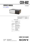
1
R
EN
TDM-7582E
TDM-7580E
CH
FM/AM Cassette Receiver
• OWNER'S MANUAL
Please read before using this equipment.
• 用戶說明書
使用本設備之前,一定請先閱讀。
ALPINE ELECTRONICS, INC.
Tokyo office: 1-1-8 Nishi Gotanda,
Shinagawa-ku,
Tokyo 141-8501, Japan
Tel.: (03) 3494-1101
ALPINE ELECTRONICS OF AMERICA, INC.
19145 Gramercy Place, Torrance,
California 90501, U.S.A.
Tel.: 1-800-ALPINE-1 (1-800-257-4631)
ALPINE ELECTRONICS OF CANADA, INC.
Suite 203, 7300 Warden Ave. Markham,
Ontario L3R 9Z6, Canada
Tel.: 1-800-ALPINE-1 (1-800-257-4631)
Melyi Printing Factory, Dalian, China
No. 28 Chang Qing Street, Xl Gang District, Dalian, China
ALPINE ELECTRONICS OF AUSTRALIA PTY. LTD.
6-8 Fiveways Boulevarde Keysborough,
Victoria 3173, Australia
Tel.: (03) 9769-0000
ALPINE ELECTRONICS GmbH
Kreuzerkamp 7-11 40878 Ratingen, Germany
Tel.: 02102-45 50
ALPINE ITALIA S.p.A.
Via C. Colombo 8, 20090 Trezzano Sul Naviglio
MI, Italy
Tel.: 02-48 47 81
ALPINE ELECTRONICS FRANCE S.A.R.L.
(RCS PONTOISE B 338 101 280)
98, Rue De La Belle Etoile, Z.I. Paris Nord Il
B.P. 50016 F-95945, Roissy, Charles De Gaulle
Cedex, France
Tel.: 01-48 63 89 89
ALPINE ELECTRONICS OF U.K., LTD.
13 Tanners Drive, Blakelands, Milton Keynes
MK14 5BU, U.K.
Tel.: 01908-61 15 56
ALPINE ELECTRONICS DE ESPAÑA, S.A.
Portal De Gamarra 36, Pabellón 32
01013 Vitoria (Alava)-Apdo. 133, Spain
Tel.: 34-45-283588
Designed by ALPINE Japan
Printed in China (Y)
68P01434K84-O
ALPINE TDM-7582CH 68P01434K84-O
CHA-S634
CHA-1214
CHM-S630
• CD changer for TDM-7582E.
• TDM-7582E 用 CD 換碟機。
Alpine CD Changers Give You More!
More musical selections, more versatility, more convenience.
The CHA-S634 is a high-performance 6-disc changer with a new M DAC, CD-R/RW PLAY BACK, MP3
PLAY BACK and CD TEXT. The CHA-1214 Ai-NET model holds 12 discs, and the CHM-S630 M-Bus
model is a super-compact 6-disc changer with a CD-R/RW PLAY BACK.
NOTE
The CHA-S634 model can be connected to the M-Bus model Head Unit using the optional M-Bus/Ai-NET compatible
cable. (KCA-130B)
Alpine CD 換碟器讓您更加滿意!
更多音樂選項,更多功能性,更佳方便性。
CHA-S634 是一個帶新型 M DAC,CD-R/RW PLAY BACK,MP3 PLAY BACK 和 CD TEXT 的高性能 6 碟式
換碟器。CHA-1214 Ai-NET 型號可裝載 12 張唱碟,CHM-S630 M-Bus 型號是一個帶 CD-R/RW PLAY
BACK 的超小型 6 碟式換碟器。
注意
使用選購的 M-Bus/Ai-NET 相容電纜可把 CHA-S634 型號連接至 M-Bus 型號主機。(KCA-130B)
ALPINE TDM-7582CH 68P01434K84-O
ENGLISH
Contents
Operating Instructions
WARNING
CD Changer Operation
Controlling CD Changer (Optional) ................ 10
Switching between Track No. and Elapsed
Time Displays ............................................... 10
WARNING .................................................. 2
CAUTION ................................................... 2
PRECAUTIONS ......................................... 2
Basic Operation
Detaching the Front Panel .................................. 4
Music Sensor (M.S.) Skip ................................ 10
Fast Forward and Backward ............................ 10
Repeat Play on Single Track or Entire Disc .... 10
M.I.X. (Random) Play ..................................... 11
Information
Attaching the Front Panel .................................. 4
In Case of Difficulty ........................................ 12
Initial System Start-Up ...................................... 4
Specifications ................................................... 13
Automatic Setup (A.S.U.) .................................. 4
Turning Power On and Off ................................ 5
Installation and Connections
Turning Loudness On/Off .................................. 5
Adjusting Volume/Bass/Treble/Balance
Warning ............................................................ 14
(Between Left and Right)/Fader
Caution ............................................................. 14
(Between Front and Rear) .............................. 5
Precautions ....................................................... 14
Displaying Time ................................................. 5
Installation ....................................................... 15
Setting Time ....................................................... 5
Connections ..................................................... 16
Radio Operation
Manual Tuning ................................................... 6
Automatic Seek Tuning ..................................... 6
Manual Storing of Station Presets ..................... 6
Automatic Memory of Station Presets ............... 7
Storing into Direct Access Preset (D.A.P.)
Band ................................................................ 7
Tuning to Preset Stations ................................... 7
Cassette Player Operation
Inserting/Ejecting Cassette ................................ 8
Normal Play ....................................................... 8
Repeat Play ........................................................ 8
Fast Forward and Rewind .................................. 9
Blank Skip (B.SKIP) .......................................... 9
Manual Reverse ................................................. 9
Programme Sensor (P.S.) ................................... 9
1-EN
WARNING
WARNING
The exclamation point within an equilateral
triangle and "WARNING" are intended to alert the
user to the presence of important operating
instructions.
Failure to heed the instructions will result in
severe injury or death.
CAUTION
The exclamation point within an equilateral
triangle and "CAUTION" are intended to alert the
user to the presence of important operating
instructions.
Failure to heed the instructions can result in injury
or material damage.
DO NOT DISASSEMBLE OR ALTER.
HALT USE IMMEDIATELY IF A PROBLEM APPEARS.
Doing so may result in an accident, fire or electric shock.
Failure to do so may cause personal injury or damage to
the product. Return it to your authorized Alpine dealer or
the nearest Alpine Service Centre for repairing.
KEEP SMALL OBJECTS SUCH AS BATTERIES OUT
OF THE REACH OF CHILDREN.
Swallowing them may result in serious injury. If
swallowed, consult a physician immediately.
USE THE CORRECT AMPERE RATING WHEN
REPLACING FUSES.
Failure to do so may result in fire or electric shock.
DO NOT OPERATE ANY FUNCTION THAT TAKES
YOUR ATTENTION AWAY FROM SAFELY DRIVING
YOUR VEHICLE.
Any function that requires your prolonged attention
should only be performed after coming to a complete stop.
Always stop the vehicle in a safe location before
performing these functions. Failure to do so may result in
an accident.
PRECAUTIONS
Temperature
Be sure the temperature inside the vehicle is between
+60°C (+140°F) and –10°C (+14°F) before turning your
unit on.
Tape Slack
Check and make sure any slack in the tape is taken up
before inserting the tape into the unit. A loose tape can get
caught in the mechanism and cause damage to the unit
and the tape itself. Tighten the tape by inserting a pencil
or a similar instrument into the spindle hole and turn until
all the slack has been taken up.
KEEP THE VOLUME AT A LEVEL WHERE YOU CAN
STILL HEAR OUTSIDE NOISE WHILE DRIVING.
Failure to do so may result in an accident.
USE THIS PRODUCT FOR MOBILE 12V
APPLICATIONS.
Excessively Thin Tape
Use for other than its designed application may result in
fire, electric shock or other injury.
C-120 type cassette tapes are not recommended for use in
automobile tape players.
DO NOT PLACE HANDS, FINGERS OR FOREIGN
OBJECTS IN INSERTION SLOTS OR GAPS.
Precision Tape Mechanism
Doing so may result in personal injury or damage to the
product.
DO NOT BLOCK VENTS OR RADIATOR PANELS.
Doing so may cause heat to build up inside and may result
in fire.
2-EN
Prevent any foreign objects from entering the cassette
opening as the precision mechanism and tape head may be
damaged.
Never play dirty or dusty tapes – they can damage the tape
head.
Tape Head Cleaning
Periodic cleaning (approximately every 20 hours of use)
of the tape head with a wet type head-cleaning cassette
tape (available at audio stores) is necessary for best
performance.
Fuse Replacement
When replacing the fuse(s), the replacement must be of
the same amperage as shown on the fuse holder. If the
fuse blows more than once, carefully check all electrical
connections for shorted circuitry. Also have your vehicle's
voltage regulator checked.
Maintenance
If you have problems, do not attempt to repair the unit
yourself. Return it to your Alpine dealer or the nearest
Alpine Service Station for servicing.
Installation Location
Make sure the TDM-7582E will not be installed in a
location subjected to:
•
•
•
•
Direct sun and heat
High humidity and water
Excessive dust
Excessive vibrations
Handling the Detachable Front Panel
• Do not expose to rain or water.
• Do not drop or apply shock.
3-EN
Basic Operation
POWER
2
MODE/LOUD
c
CLOCK
A.S.U.
ZERO
1
HOUR
MIN
Detaching the Front Panel
Initial System Start-Up
1
2
1
3
Press the POWER button to turn off the power.
Press the
(Release) button until the front
panel pops out.
Grasp the left side of the front panel and pull it
out.
NOTES
• The front panel may become hot (especially the connector
terminals). This is not a malfunction.
• To protect the front panel, place it in the supplied carrying
case.
Immediately after installing or applying power to
the unit, it should be initialized. To do this, first,
remove the detachable front panel. Behind the
front panel, to the right of the connector, there is
a small hole. Using a pencil or other pointed
object, press the red Reset switch mounted
behind this hole to complete the initialization
procedure.
Reset switch
Automatic Setup (A.S.U.)
This convenient feature sets up the unit
automatically after installation.
Attaching the Front Panel
1
2
First, insert the right side of the front panel into
the main unit. Align the 2 small holes on the front
panel with the 2 projections on the main unit.
Push the left side of the front panel until it locks
firmly into the main unit.
2
1
NOTE
Before attaching the front panel, make sure that there is no
dirt or dust on the connector terminals and no foreign object
between the front panel and the main unit.
4-EN
1
Press the POWER button to turn on the unit.
NOTE
When Power is turned on for the very first time, the
A.S.U. (Automatic Set-Up) function will be initiated
automatically. See A.S.U. description below.
2
Press and hold the A.S.U. (Automatic Setup)
button for at least 3 seconds to activate the
A.S.U. mode.
"ASU" blinks in the display.
The unit automatically performs the following
operations.
1. Activates the Auto Memory mode.
2. Gradually sets the Bass, Treble, Balance and
Fader controls to their center positions.
3. Gradually increases the volume to the
position 12 in the display.
4. Turns the Loudness on.
5. Ends the A.S.U. mode.
2
NOTE
The BASS and TREBLE settings for each source (FM,
AM, TAPE, and CD) are automatically memorized. These
settings remain until you manually change them.
Displaying Time
1
Press the POWER button to turn on the unit.
2
NOTE
The unit can be turned on by pressing any other button
except the eject c button.
Setting Time
The volume level gradually increases to the
previous level you were listening to before the
unit was turned off. Press the POWER button
again to turn off the unit.
Turning Loudness On/Off
Loudness introduces a low- and high-frequency
emphasis to compensate for the ear's decreased
sensitivity to bass and treble sound at low
listening levels.
1
Press the CLOCK button to display the time. The
unit displays the clock time.
NOTE
Selecting any of the tuner, tape and CD functions while
in the clock mode will interrupt the time display
momentarily. The function selected will be displayed for
about 5 seconds before the time returns to the display.
Turning Power On and Off
1
Press the Kor Lbutton until the desired sound
is obtained in each mode.
Press and hold the LOUD button for at least
2 seconds to activate or deactivate the loudness
mode. The display shows "LOUD" when the
loudness mode is activated.
1
2
3
4
Press the CLOCK button to turn off the time and
to show other functions.
Press and hold the CLOCK button for at least 2
seconds while the display is showing the time.
The time indication will begin to blink (for 5
seconds).
Press the ZERO button while the time indication
is blinking to set seconds to "0."
Press the HOUR button to adjust the hours while
the time indication is blinking.
Press the MIN button to adjust the minutes while
the time indication is blinking.
The time indication will stop blinking 5 seconds
after the last adjustment. The time will
automatically be set.
Adjusting Volume/Bass/Treble/
Balance (Between Left and Right)/
Fader (Between Front and Rear)
1
Press the MODE button repeatedly to choose
the desired mode.
Each press changes the modes as follows:
→ VOL
→ BAS
→TRE
FAD ←
BAL ←
NOTE
If the Kor Lbutton is not pressed within 5 seconds
after selecting BASS, TREBLE, BALANCE, or FADER
mode, the unit automatically returns to VOLUME mode.
5-EN
Radio Operation
BAND/D.A.P.
SOURCE
g DN
f UP
Preset buttons (1 through 6)
TUNE / A.ME
Manual Tuning
1
2
Press the SOURCE button until radio frequency
appears in the display.
Press the BAND button repeatedly until the
desired radio band is displayed.
Each press changes the radio bands as follows:
→ F1 → F2 → AM
3
Press the TUNE button repeatedly until "DX
SEEK" and "SEEK" disappears from the display.
NOTE
The initial mode is DX SEEK.
4
Automatic Seek Tuning
2
Press the SOURCE button until radio frequency
appears in the display.
Press the BAND button repeatedly until the
desired radio band is displayed.
Each press changes the radio bands as follows:
→ F1 → F2 → AM
3
Press the TUNE button to illuminate the DX and
SEEK indicators in the display.
With the DX mode activated, both strong and
weak stations will be tuned in the Auto-Seek
operation.
Press again to return to the local mode. The DX
indicator will turn off and the SEEK indicator will
remain illuminated. Now, only strong stations will
be tuned.
6-EN
Press the g DN or f UP button to
automatically seek for a station downward or
upward respectively.
The unit will stop on the next station it finds.
Press the same button again to seek the next
station.
Manual Storing of Station Presets
1
2
Press the g DN or f UP button to move
downward or upward one step respectively until
the desired station frequency is displayed.
NOTE
"ST" indicator appears when a stereo FM station is tuned
in.
1
4
3
Select the radio band and tune in a desired radio
station you wish to store in the preset memory.
Press and hold the Preset buttons (1 through
6) that you want to store the station on for at
least 2 seconds.
The selected station is stored.
The display shows the band, preset No. with a
triangle (9) and station frequency memorized.
Repeat the procedure to store up to 5 other
stations onto the same band.
To use this procedure for other bands, simply
select the band desired and repeat the
procedure.
A total of 24 stations can be stored in the preset
memory (6 stations for each band; FM1, FM2,
AM and D.A.P.).
NOTE
If you store a station in a preset memory which already
has a station, the current station will be cleared and
replaced with the new station.
Automatic Memory of Station
Presets
1
2
Press the SOURCE button until the radio
frequency appears in the display.
Tuning to Preset Stations
1
2
Press the BAND button repeatedly until the
desired radio band is displayed.
Each press changes the radio bands as follows:
Press and hold the A. ME button for at least 2
seconds.
The frequency on the display continues to
change while the automatic memory is in
progress.
The tuner will automatically seek and store 6
strong stations in the selected band in order of
signal strength.
When the automatic memory has been
completed, the tuner goes to the station stored in
the preset location No. 1.
Press the BAND button repeatedly until the
desired band is displayed.
Each press changes the radio bands as follows:
→ F1 → F2 → AM
→ F1 → F2 → AM
3
Press the SOURCE button until the radio
frequency appears in the display.
To select the D.A.P. band, press and hold the
D.A.P. button for at least 2 seconds until the
D.A.P. indicator appears in the display.
3
Press the station preset button that has your
desired radio station in memory.
The display shows the band, preset number with
a triangle and frequency of the station selected.
NOTE
If no stations are stored, the tuner will return to the
original station you were listening to before the auto
memory procedure began.
Storing into Direct Access Preset
(D.A.P.) Band
A combination of radio stations in any band (up to
6 stations) can be manually preset into the D.A.P.
band.
1
Press and hold the D.A.P. button for at least 2
seconds until the D.A.P. indicator appears.
Press the BAND button to select FM or AM.
The selected band will be displayed.
To memorize stations onto the D.A.P. band,
follow the steps for the automatic or Manual
Storing of Station Presets section above.
NOTE
When using the Automatic Memory function with D.A.P.,
the first 3 presets will be filled with FM stations and the
last 3 are filled with AM stations.
To cancel the D.A.P. mode, press and hold the
D.A.P. button for at least 2 seconds. The D.A.P.
indicator will turn off.
7-EN
Cassette Player Operation
PROG
c
REPEAT
SOURCE
g DN
f UP
:/J
B.SKIP
P.S.DN
Inserting/Ejecting Cassette
Normal Play
1
1
Insert a cassette tape into the slot with the open
side facing right.
P.S.UP
Insert a cassette tape into the slot with the open
side facing to the right.
The player automatically starts tape playback
and the display shows "TAPE" and the tape side
being played ( or ).
When the end of the tape is reached, the player
automatically reverses the tape direction and
plays the other side of the tape.
When the cassette is loaded, the player
automatically starts tape playback and indicates
"TAPE" in the display.
2
Press the Eject (c) button when you want to
eject the cassette tape.
If a tape is already loaded in the cassette player,
press the SOURCE button to select the TAPE
mode.
2
3
NOTES
• When power is turned off or the front panel is
removed, the full-logic mechanism will automatically
switch to the PAUSE mode. This protects the tape from
being deformed by the pinch-rollers if left for long
periods.
• Auto Metal
When a metal cassette tape is inserted, the player
automatically adjusts the equalization for metal or any
other high bias tape for optimum sound.
The display shows "MTL."
8-EN
Press the :/J button to pause the tape
playback.
Both tape direction indicators appear during the
pause mode.
Press again to resume the tape playback.
Press the Eject (c) button to stop the tape play
and eject the cassette.
The tape-direction indicator disappears.
Repeat Play
1
Press the REPEAT button and the "REPEAT"
indicator appears in the display.
The current programme will be played back
repeatedly.
Press the REPEAT button to stop the repeat
play.
The "REPEAT" indicator disappears.
Fast Forward and Rewind
Programme Sensor (P.S.)
1
1
2
Press the g DN or f UP button during
tape play to fast rewind or forward the tape
respectively.
or
blinks indicating
The tape side indicator
the direction of the tape. When the end of the
tape is reached in the fast rewind mode, the
player stops automatically and begins playing
from the beginning of the same side.
When the end of the tape is reached in the fast
forward mode, the player stops automatically and
begins playing from the beginning of the
opposite side.
Press the f UP button during forwarding to
stop fast forwarding and resume tape play.
Press the g DN button during rewinding to
stop rewinding and resume tape play.
The tape side indicator stops blinking.
Blank Skip (B.SKIP)
1
Press the B.SKIP button during tape play to skip
over blank portions of the tape lasting 15
seconds or longer, "B.SKIP" appears on the
display.
Press the B.SKIP button to cancel the blank skip
mode.
"B.SKIP" disappears from the display.
Press the P.S. DN button once during tape play
to return to the beginning of the current selection
being played.
If you wish to return to the beginning of a
selection further back, press repeatedly until the
number of selections you would like to skip is
shown in the display.
The display will show PS-1 with the first press
and will increase by one with each successive
press up to PS-9. The tape indicator will blink
showing the direction of your search.
Press the P.S. UP button once during tape play
to advance to the beginning of the next selection.
If you wish to advance to the beginning of a
selection further ahead, press repeatedly until
the number of selections you would like to skip is
shown in the display.
The display will show PS+1 with the first press
and will increase by one with each successive
press up to PS+9. The tape indicator will blink
showing the direction of your search during
searching operation.
NOTES
• The programme sensor feature is functional in the tape
play mode only.
• You can advance to the 9th (max.) programme or
return to the 8th (max.) programme.
Manual Reverse
1
Press the PROG button during tape play to
change the direction of play.
The tape side indicators ( and ) change to
show which side of the cassette is being played.
9-EN
CD Changer Operation
SOURCE
REPEAT/M.I.X.
CLOCK
g DN
f UP
:/J
Controlling CD Changer (Optional)
The CD controls on the TDM-7582E will function
only when a CD Changer (M-Bus) is connected.
1
Preset buttons
Music Sensor (M.S.) Skip
1
Press the SOURCE button to activate the CD
Changer.
The display shows the disc number and track
number.
Press the f UP button once to advance to the
beginning of the next track.
If you wish to advance to the beginning of a track
further ahead, press repeatedly until the desired
track is reached.
NOTE
To start play or pause playback, press the :/J button.
2
1
2
NOTE
The music sensor feature is functional in the play or
pause mode.
When a 6-disc CD Changer is connected:
Press the Preset buttons to select the desired
disc loaded in the CD Changer.
Switching between Track No. and
Elapsed Time Displays
Fast Forward and Backward
1
Each press of the CLOCK button during CD
playback causes change of the display between
the track number and clock time.
Press and hold the CLOCK button for at least 2
seconds while the track number is displayed.
The display changes to show the elapsed time
for the track being played.
Momentarily press the g DN button once to
return to the beginning of the current track.
If you wish to return to the beginning of a track
further back, repeatedly press until you reach the
desired track.
Press and hold the g DN or f UP button to
quickly move backward or forward respectively
until you reach the desired portion.
NOTE
This feature works only in the CD playback mode.
Repeat Play on Single Track or
Entire Disc
1
Press the REPEAT button to display "REPEAT"
or "REPEAT ALL" to play back repeatedly the
current track being played or the entire disc
selected.
NOTE
Single track cannot be repeated during M.I.X. play.
10-EN
M.I.X. (Random) Play
1
Press and hold the M.I.X. button in CD play for at
least 2 seconds to turn on the M.I.X. mode.
When this mode is turned on, the tracks on the
currently playing disc will be played back in a
random sequence.
To cancel the M.I.X. mode, press and hold the
M.I.X. button for at least 2 seconds.
The "M.I.X." indicator disappears from the
display.
NOTE
Single track cannot be repeated during M.I.X. play.
11-EN
Information
In Case of Difficulty
If you encounter a problem, please turn the power
off, then on again. If the unit is still not functioning
normally, please review the items in the following
checklist. This guide will help you isolate the
problem if the unit is at fault. Otherwise, make
sure the rest of your system is properly connected
or consult your authorized Alpine dealer.
Basic
No function or display.
• Vehicle's ignition is off.
- If connected following instructions, the unit will not
operate with the vehicle's ignition off.
• Improper power lead connections.
- Check power lead connections.
• Blown fuse.
- Check the fuse on the battery lead of the unit; replace
with the proper value if necessary.
Radio
Unable to receive stations.
• No antenna or open connection in cable.
- Make sure the antenna is properly connected; replace
the antenna or cable if necessary.
Unable to tune stations in the seek mode.
• You are in a weak signal area.
- Make sure the tuner is in the DX mode.
• If the area you are in is a primary signal area, the
antenna may not be grounded and connected properly.
- Check your antenna connections; make sure the
antenna is properly grounded at its mounting location.
• The antenna may not be the proper length.
- Make sure the antenna is fully extended; if broken,
replace the antenna with a new one.
Broadcast is noisy.
• The antenna is not the proper length.
- Extend the antenna fully; replace it if it is broken.
• The antenna is poorly grounded.
- Make sure the antenna is grounded properly at its
mounting location.
Cassette
Tape playback sounds dull.
• The tape head needs cleaning.
- Clean the tape head.
12-EN
CD
CD Changer not functioning.
• Out of operating temperature range +50˚C (+120˚F)
for CD.
- Allow the vehicle's interior (or trunk) temperature to
cool.
CD playback sound is wavering.
• Moisture condensation in the CD Module.
- Allow enough time for the condensation to evaporate
(about 1 hour).
Unable to fast forward or backward the CD.
• The CD has been damaged.
- Eject the CD and discard it; using a damaged CD in
your unit can cause damage to the mechanism.
CD playback sound skips due to vibration.
• Improper mounting of the CD Changer.
- Securely re-mount the CD Changer.
• Disc is very dirty.
- Clean the disc.
• Disc has scratches.
- Change the disc.
CD playback sound skips without vibration.
• Dirty or scratched disc.
- Clean the disc; damaged disc should be replaced.
Single (8 cm) disc does not play.
• Single CD adaptor is not used.
- Attach a single CD adaptor (recommended by Alpine)
to the single disc and insert into the CD magazine.
Indication for CD Changer
–––H
Specifications
FM TUNER SECTION
Tuning Range
Mono Usable Sensitivity
50 dB Quieting Sensitivity
Alternate Channel Selectivity
Signal-to-Noise Ratio
Stereo Separation
Capture Ratio
• Protective circuit is activated due to high temperature.
- The indicator will disappear when the temperature
returns to within operation range.
E - 01
• Malfunction in the CD Changer.
- Consult your Alpine dealer. Press the magazine eject
button and pull out the magazine.
Check the indication. Insert the magazine again.
If the magazine cannot be pulled out, consult your
Alpine dealer.
• Magazine ejection not possible.
- Press the magazine eject button. If the magazine does
not eject, consult your Alpine dealer.
87.5 – 108.0 MHz
9.3 dBf (0.8 µV/75 ohms)
13.5 dBf (1.3 µV/75 ohms)
80 dB
65 dB
35 dB
2.0 dB
AM TUNER SECTION
Tuning Range
Usable Sensitivity
531 – 1,602 kHz
22.0 µV
TAPE PLAYER SECTION
Tape Speed
Wow & Flutter
Tape Signal-to-Noise Ratio
Frequency Response
With Alpine Test Tape
1-7/8 ips (4.8 cm/sec) ±0.7%
0.06%
60 dB
30–20,000 Hz (±3 dB)
––––
GENERAL
• No magazine is loaded into the CD Changer.
- Insert a magazine.
Power Requirement
14.4 V DC
(11–16 V allowable)
Maximum Pre-Output Voltage 2 V/10k ohms
Maximum Power Output*
45 W × 4
Continuous Power Output**
19.5 W × 4
Output Voltage
500 mV/10 k ohms
Bass
±15 dB at 30 Hz
Treble
±10 dB at 10 kHz
Weight
1.4 kg (3 lbs. 1 oz)
T–––
• No indicated disc.
- Choose another disc.
EEEE
• Misconnection or disconnection of CD Changer.
- Check connection between CD Changer and control
unit.
CHASSIS SIZE
Width
Height
Depth
178 mm (7")
50 mm (2")
155 mm (6-1/8")
NOSEPIECE SIZE
Width
Height
Depth
170 mm (6–3/4")
46 mm (1-13/16")
19 mm (3/4")
Due to continuous product improvement, specifications and
design are subject to change without notice.
*
Under maximum operating voltage and input signal,
into 4 ohms.
** 0.8% THD, at 14.4 V battery voltage.
13-EN
Installation and Connections
Before installing or connecting the unit, please
read the following and pages 2 and 3 of this
manual thoroughly for proper use.
Warning
USE ONLY IN CARS WITH A 12 VOLT NEGATIVE
GROUND.
(Check with your dealer if you are not sure.) Failure to do
so may result in fire, etc.
BEFORE WIRING, DISCONNECT THE CABLE FROM
THE NEGATIVE BATTERY TERMINAL.
Failure to do so may result in electric shock or injury due
to electrical shorts.
DO NOT SPLICE INTO ELECTRICAL CABLES.
Never cut away cable insulation to supply power to other
equipment. Doing so will exceed the current carrying
capacity of the wire and result in fire or electric shock.
DO NOT INSTALL IN LOCATIONS WHICH MIGHT
HINDER VEHICLE OPERATION, SUCH AS THE
STEERING WHEEL OR SHIFT LEVER.
Doing so may obstruct forward vision or hamper
movement etc. and results in serious accident.
DO NOT DAMAGE PIPE OR WIRING WHEN
DRILLING HOLES.
When drilling holes in the chassis for installation, take
precautions so as not to contact, damage or obstruct pipes,
fuel lines, tanks or electrical wiring. Failure to take such
precautions may result in fire.
DO NOT USE BOLTS OR NUTS IN THE BRAKE OR
STEERING SYSTEMS TO MAKE GROUND
CONNECTIONS.
Bolts or nuts used for the brake or steering systems (or
any other safety-related system), or tanks should NEVER
be used for installations or ground connections. Using
such parts could disable control of the vehicle and cause
fire etc.
MAKE THE CORRECT CONNECTIONS.
Failure to make the proper connections may result in fire
or product damage.
Caution
ARRANGE THE WIRING SO IT IS NOT CRIMPED OR
PINCHED BY A SHARP METAL EDGE.
Route the cables and wiring away from moving parts (like
the seat rails) or sharp or pointed edges. This will prevent
crimping and damage to the wiring. If wiring passes
through a hole in metal, use a rubber grommet to prevent
the wire’s insulation from being cut by the metal edge of
the hole.
14-EN
HAVE THE WIRING AND INSTALLATION DONE BY
EXPERTS.
The wiring and installation of this unit requires special
technical skill and experience. To ensure safety, always
contact the dealer where you purchased this product to
have the work done.
USE SPECIFIED ACCESSORY PARTS AND INSTALL
THEM SECURELY.
Be sure to use only the specified accessory parts. Use of
other than designated parts may damage this unit
internally or may not securely install the unit in place.
This may cause parts to become loose resulting in hazards
or product failure.
DO NOT INSTALL IN LOCATIONS WITH HIGH
MOISTURE OR DUST.
Avoid installing the unit in locations with high incidence
of moisture or dust. Moisture or dust that penetrates into
this unit may result in product failure.
Precautions
• Be sure to disconnect the cable from the (–) battery post
before installing your TDM-7582E. This will reduce
any chance of damage to the unit in case of a shortcircuit.
• Be sure to connect the color coded leads according to
the diagram. Incorrect connections may cause the unit
to malfunction or damage to the vehicle’s electrical
system.
• When making connections to the vehicle’s electrical
system, be aware of the factory installed components
(e.g. on-board computer). Do not tap into these leads to
provide power for this unit. When connecting the
TDM-7582E to the fuse box, make sure the fuse for the
intended circuit of the TDM-7582E has the appropriate
amperage. Failure to do so may result in damage to the
unit and/or the vehicle. When in doubt, consult your
ALPINE dealer.
• The TDM-7582E uses female RCA-type jacks for
connection to other units (e.g. amplifier) having RCA
connectors. You may need an adaptor to connect other
units. If so, please contact your authorized ALPINE
dealer for assistance.
• Be sure to connect the speaker (–) leads to the speaker
(–) terminal. Never connect left and right channel
speaker cables to each other or to the vehicle body.
IMPORTANT
Please record the serial number of your unit in the
space provided below and keep it as a permanent
record. The serial number plate is located on the
bottom of the unit.
SERIAL NUMBER:
INSTALLATION DATE:
INSTALLATION TECHNICIAN:
PLACE OF PURCHASE:
3
Installation
1
Mounting sleeve
(Included)
Dashboard
Lock Pin
TDM-7582E
Remove the Detachable Front Panel (refer to page
4). Slide mounting sleeve from main unit. Slide the
mounting sleeve into the dashboard.
Slide the TDM-7582E into the dashboard. When
the unit is in place, make sure the locking pins are
fully seated in the down position. This can be done
by pressing firmly in on the unit while pushing the
locking pin down with a small screwdriver. This
ensures that the unit is properly locked and will not
accidentally come out from the dashboard. Install
the Detachable Front Panel.
Removal
2
Metal Mounting
Strap
Screw
Bolt Stud
Hex Nut (M5)
1. Remove the Detachable Front Panel.
2. Use a small screwdriver (or similar tool) to
push the locking pins to the "up" position
(see above drawing). As each pin is
unlocked, gently pull out on the unit to make
sure it does not re-lock before unlocking the
second pin.
3. Pull the unit out, keeping it unlocked as you
do so.
<JAPANESE CAR>
Ground Lead
Chassis
∗
TDM-7582E
Reinforce the head unit with the metal mounting
strap (not supplied). Secure the ground lead of the
unit to a clean metal spot using a screw (∗) already
attached to the vehicle's chassis.
Connect each input lead coming from an amplifier
or equalizer to the corresponding output lead
coming from the left rear of the TDM-7582E.
Connect all other leads of the TDM-7582E
according to details described in the
CONNECTlONS section.
Face Plate
Screw (M5 × 8)
(Included)
Ground Lead TDM-7582E
∗
Mounting Bracket
15-EN
Installation and Connections
Connections
Antenna
2
Blue
POWER ANT
Blue/White
REMOTE
TURN-ON
Red
IGNITION
4
Yellow
BATTERY
6
Black
GND
7
To power antenna
3
To amplifier or equaliser
Ignition Key
5
Battery
TDM-7582E
A
1
DIN Connector PIN Configuration.
~
Power Supply Ground
lgnition
)
Shield Ground
Data Ground
+
Battery
Lch
A
8
Data Bus
SIG GND
Rch
SPEAKER
RIGHT
FRONT
SPEAKER
RIGHT
REAR
Grey
9
Gray/
Black
!
Violet/
Black
"
Violet
#
Green
$
Front right
Rear right
Speakers
SPEAKER
LEFT
REAR
SPEAKER
LEFT
FRONT
Green/
Black
%
White/
Black
&
White
(
Rear left
Front left
CD Changer
(Sold Separately)
Rear left
,
Amplifier
Rear right
16-EN
1 Antenna Receptacle
2 Power Antenna Lead (Blue)
Connect this lead to the +B terminal of your power
antenna, if applicable.
NOTE
This lead should be used only for controlling the vehicle's
power antenna. Do not use this lead to turn on an
amplifier or a signal processor, etc.
3 Remote Turn-On Lead (Blue/White)
Connect this lead to the remote turn-on lead of your
amplifier or signal processor.
4 Switched Power Lead (Ignition) (Red)
Connect this lead to an open terminal on the vehicle's
fuse box or another unused power source which
provides (+) 12V only when the ignition is turned on
or in the accessory position.
5 Fuse Holder (15A)
6 Battery Lead (Yellow)
Connect this lead to the positive (+) post of the
vehicle's battery.
7 Ground Lead (Black)
Connect this lead to a good chassis ground on the
vehicle. Make sure the connection is made to bare
metal and is securely fastened using the sheet metal
screw provided.
8 Power Supply Connector
9 Right Front (+) Speaker Output Lead (Grey)
! Right Front (–) Speaker Output Lead (Grey/
Black)
" Right Rear (–) Speaker Output Lead (Violet/
Black)
# Right Rear (+) Speaker Output Lead (Violet)
$ Left Rear (+) Speaker Output Lead (Green)
% Left Rear (–) Speaker Output Lead (Green/Black)
& Left Front (–) Speaker Output Lead (White/Black)
( Left Front (+) Speaker Output Lead (White)
) DIN Connector
Connect this to the DIN connector on the CD
Changer.
~ Rear Output RCA Connectors
RED is right and WHITE is left.
+ DIN Extension Cable
NOTE
For some installations, an L-type DIN connector would
simplify installation. Use the Alpine 491002 Adapter (Sold
Separately) if your changer did not include an L-type
DIN.
, RCA Extension Cable (Sold Separately)
17-EN