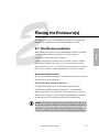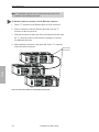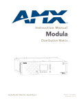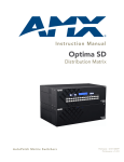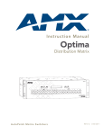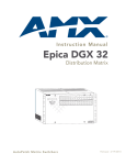
1
Modula
Installation
and Setup
Guide
909943
CAUTION
To avoid ESD (Electrostatic Discharge) damage to sensitive components,
make sure you are properly grounded before touching any internal
materials. When working with any equipment manufactured with
electronic devices, proper ESD grounding procedures must be followed
to ensure people, products, and tools are as free of static charges as
possible. Grounding straps, conductive smocks, and conductive work
mats are specifically designed for this purpose. Anyone performing field
maintenance on AutoPatch equipment should utilize an appropriate ESD
field service kit complete with at least a dissipative work mat with a
ground cord and a UL listed adjustable wrist strap with another ground
cord. These items should not be manufactured locally, since they are
generally composed of highly resistive conductive materials to safely
drain static charges, without increasing an electrocution risk in the event
of an accident. ESD protective equipment can be obtained from 3M™,
Desco®, Richmond Technology®, Plastic Systems®, and other such
vendors.
Installation and Setup Guide
Important Safety Information
and Instructions
When using and installing your AutoPatch product, adhere to the following basic safety
precautions. For more information about operating, installing, or servicing your
AutoPatch product see your product documentation.
ä Read and understand all instructions before using and installing AutoPatch products.
ä Use the correct voltage range for your AutoPatch product.
ä There are no user serviceable parts inside an AutoPatch product; service should only
be done by qualified personnel.
ä If you see smoke or smell a strange odor coming from your AutoPatch product, turn
it off immediately and call AutoAssist.
ä Turn off and unplug an enclosure before adding or removing boards, unless otherwise
specified in that product’s documentation.
ä To avoid shock or potential ESD (Electrostatic Discharge) damage to equipment,
make sure you are properly grounded before touching components inside an
AutoPatch product.
ä For products with multiple power supplies in each unit, make sure all power supplies
are turned on simultaneously.
ä Use surge protectors and/or AC line conditioners when powering AutoPatch
products.
ä Only use a fuse(s) with the correct fuse rating in your enclosure.
ä Make sure the power outlet is close to the product and easily accessible.
ä Make sure the product is on or attached to a stable surface.
ä Turn off equipment before linking pieces together, unless otherwise specified in that
product’s documentation.
ä For safety and signal integrity, use a grounded external power source and a grounded
power connector.
Installation and Setup Guide
Information et directives
de sécurité importantes
Veuillez vous conformer aux directives de sécurité ci-dessous lorsque vous installez et
utilisez votre appareil AutoPatch. Pour de plus amples renseignements au sujet de
l’installation, du fonctionnement ou de la réparation de votre appareil AutoPatch, veuillez
consulter la documentation accompagnant l’appareil.
ä Lisez attentivement toutes les directives avant d’installer et d’utiliser les appareils
AutoPatch.
ä Le voltage doit être approprié à l’appareil AutoPatch.
ä Les appareils AutoPatch ne contiennent aucune pièce réparable par l’usager; la
réparation ne doit être effectuée que par du personnel qualifié.
ä Si de la fumée ou une odeur étrange se dégagent d’un appareil AutoPatch, fermez-le
immédiatement et appelez le Service de soutien technique (AutoAssist).
ä Fermez et débranchez le boîtier avant d’ajouter ou d’enlever des plaquettes, à moins
d’indication contraire fournie dans la documentation du appareil.
ä Pour éviter les chocs ou les dommages éventuels causés à l’équipement par une
décharge électrostatique, veillez à ce le dispositif oit bien relié à la terre avant de
toucher les composantes se trouvant à l’intérieur d’un appareil AutoPatch.
ä Veillez à ce que tous les blocs d’alimentation des appareils dotés de blocs
d’alimentation multiples dans chaque unité soient allumés simultanément.
ä Servez-vous de protecteurs de surtension ou de conditionneurs de lignes à courant
alternatif lorsque vous mettez les appareils AutoPatch sous tension.
ä Placez uniquement des fusibles de calibre exact dans les boîtiers.
ä Veillez à ce que la prise de courant soit proche de l’appareil et facile d’accès.
ä Veillez à ce que votre appareil AutoPatch soit installé sur une surface stable ou qu’il
y soit fermement maintenu.
ä Fermez toutes les composantes de l’équipement avant de relier des pièces, à moins
d’indication contraire fournie dans la documentation de l’appareil.
ä Par mesure de sécurité et pour la qualité des signaux, servez-vous d’une source
d’alimentation externe mise à la terre et d’un connect d’alimentation mis à la terre.
Installation and Setup Guide
Notices
AutoPatch© 2001, all rights reserved. No part of this publication may be reproduced,
stored in a retrieval system, or transmitted, in any form or by any means, electronic,
mechanical, photocopying, recording, or otherwise, without the prior written permission
of AutoPatch. Copyright protection claimed extends to AutoPatch hardware and software
and includes all forms and matters copyrightable material and information now allowed
by statutory or judicial law or here in after granted, including without limitation, material
generated from the software programs which are displayed on the screen such as icons,
screen display looks, etc. Reproduction or disassembly of embodied computer programs
or algorithms is expressly prohibited.
No patent liability is assumed with respect to the use of information contained herein.
While every precaution has been taken in the preparation of this publication, AutoPatch
assumes no responsibility for error or omissions. No liability is assumed for damages
resulting from the use of the information contained herein.
Further, this publication and features described herein are subject to change without
notice. The United States Federal Communications Commission (in 47CFR 15.838) has
specified that the following notice be brought to the attention of the users of this product.
Federal Communication Commission Radio Frequency Interference Statement:
“This equipment generates and uses radio frequency energy and if not installed and used
properly, that is, in strict accordance with the manufacturers instructions, may cause
interference to radio and television reception. It has been type-tested and found to
comply with the limits for a Class B computing device in accordance with the
specifications in Subpart J of Part 15 of FCC Rules, which are designed to provide
reasonable protection against such interference in a residential installation. However
there is no guarantee that interference will not occur in a particular installation. If this
equipment causes interference to radio or television reception, which can be determined
by turning the equipment off and on, the user is encouraged to try to correct the
interference by one or more of the following measures:
ä Reorient the receiving antenna
ä Relocate the matrix with respect to the receiver
ä Move the matrix away from the receiver
ä Plug the matrix into a different outlet so that computer and receiver are on different
branch circuits
Installation and Setup Guide
If necessary, the user should consult the dealer or an experienced radio/television
technician for additional suggestions. The user may find the booklet, How to Identify
and Resolve Radio-TV Interference Problems, prepared by the Federal Communications
Commission to be helpful.”
This booklet is available from the U.S. Government Printing Office, Washington, D.C.
20402, Stock N. 004-000-00345-4.
Modula™, XNNet™, and XNConnect™ are trademarks of XNTechnologies, Inc.
Use shielded cables. To comply with FCC Class B requirement, all external data interface
cables and adapters must be shielded.
MS-DOS, Windows, and Windows95 are registered trademarks of Microsoft
Corporation.
3M, Desco, Richmond Technology, and Plastic Systems are all registered trademarks.
®
®
Neuron and LonTalk are registered trademarks of Echelon.
Installation and Setup Guide
Warranty
AutoPatch
Statement of Warranty
AutoPatch, a division of XN Technologies, Inc., Cheney, Washington,
warrantees that the products manufactured by AutoPatch will be free of defects
in materials and workmanship for the lifetime of the product, subject to the
following terms and conditions.
Terms and Conditions
1.
AutoPatch products are under warranty for a period of five (5) years
following the original sales invoice date. The warranty period may be
extended to the life of the product provided the warranty card is filled out
and returned to AutoPatch. TO VALIDATE THE LIFETIME
WARRANTY: THE AutoPatch WARRANTY CARD MUST BE FILLED
OUT BY THE DEALER AND RECEIVED BY AutoPatch WITHIN
THIRTY (30) DAYS OF THE INSTALLATION OF EQUIPMENT BUT
NO LATER THAN ONE (1) YEAR FROM THE ORIGINAL SALES
INVOICE DATE. A warranty certificate will be returned to the dealer to
verify the warranty period.
2.
This Limited Lifetime warranty covers AutoPatch products shipped on or
after October 1, 1997. The Limited Lifetime warranty applies to products
in the original installation only. If the product is moved to a different
installation, the Limited Lifetime warranty will no longer apply and the
product warranty will revert to the original warranty which covers a period
of five (5) years following the original sales invoice date.
3.
The product lifetime is defined as the period of time from the original sales
invoice date to ten (10) years after AutoPatch ceases manufacturing the
product model.
4.
Warranty repairs are accomplished by returning the subassembly to
AutoPatch for repair. If conditions do not permit this procedure, AutoPatch
will invoice new or reconditioned (at AutoPatch’s option) replacement parts
and ship them to the dealer or to the customer if so directed by written order
from the dealer. In that case the replacement will be billed to the customer
and the customer may return the failed subassembly within 30 days for
credit. See “AutoPatch Returns Policy” in this manual for replacement
policies and procedures.
Installation and Setup Guide
Warranty
5.
AutoPatch’s liability and Buyer’s remedies under this warranty shall
be limited solely to repair, replacement, or credit, at AutoPatch’s
option.
6.
The AutoPatch warranty does not apply to any AutoPatch product that has
been modified, repaired by an unauthorized agent, or improperly installed,
used, or maintained. AutoPatch shall not be liable under any circumstances
for consequential or incidental damages including, but not limited to, labor
costs or loss of profits arising in connection with the use of or inability to
use AutoPatch products.
7.
AutoPatch will not be responsible for items damaged during shipment to or
from AutoPatch. The shipping carrier is responsible for items damaged
during shipment.
8.
This warranty is exclusive and in lieu of any other warranty, expressed or
implied, including but not limited to any implied merchantability or fitness
for a particular purpose. The terms of this warranty are governed by the
laws of the state of Washington; certain other states restrict warranty
limitations. You may have rights that are not defined herein.
9.
This warranty may not be modified except in writing by an authorized
AutoPatch officer.
Installation and Setup Guide
Contents
Welcome
Installer’s Product Notes . . . . . . . . . . . . . . . . . . . . . . . . . . . . . . . . . . . . . . . . ii
Meet the Manual. . . . . . . . . . . . . . . . . . . . . . . . . . . . . . . . . . . . . . . . . . . . . . . iii
Terms to Know . . . . . . . . . . . . . . . . . . . . . . . . . . . . . . . . . . . . . . . . . . . . . . . . iv
Technical Support. . . . . . . . . . . . . . . . . . . . . . . . . . . . . . . . . . . . . . . . . . . . . . vi
Chapter 1 — Unpacking the Modula
Front of the Enclosure . . . . . . . . . . . . . . . . . . . . . . . . . . . . . . . . . . . . . . . . 1-2
CP-20MD Control Panel . . . . . . . . . . . . . . . . . . . . . . . . . . . . . . . . . . 1-3
CP-10MD Control Panel . . . . . . . . . . . . . . . . . . . . . . . . . . . . . . . . . . 1-4
Rear of the Enclosure . . . . . . . . . . . . . . . . . . . . . . . . . . . . . . . . . . . . . . . . 1-6
Software Version. . . . . . . . . . . . . . . . . . . . . . . . . . . . . . . . . . . . . . . . . . . . . 1-8
Chapter 2 — Placing the Enclosure(s)
Site Recommendations . . . . . . . . . . . . . . . . . . . . . . . . . . . . . . . . . . . . . . . 2-1
General Hazard Precautions . . . . . . . . . . . . . . . . . . . . . . . . . . . . . . 2-1
Installation Procedure . . . . . . . . . . . . . . . . . . . . . . . . . . . . . . . . . . . . . . . . 2-3
Chapter 3 — Linking Enclosures
Chapter 4 — Attaching Inputs and Outputs
Chapter 5 — Attaching an External Controller
Chapter 6 — Applying Power and the Startup Sequence
Applying Power . . . . . . . . . . . . . . . . . . . . . . . . . . . . . . . . . . . . . . . . . . . . . . 6-2
Startup from the CP-20MD Control Panel. . . . . . . . . . . . . . . . . . . . . . 6-2
Startup from the CP-10MD Control Panel . . . . . . . . . . . . . . . . . . . . . . 6-2
Startup from a Serial Control Device . . . . . . . . . . . . . . . . . . . . . . . . . . . 6-3
Installation and Setup Guide
Chapter 7 — Executing a Test Switch
Executing a Test Switch Using the CP-20MD Control Panel. . . . . . . 7-2
Executing a Test Switch Using the CP-10MD Control Panel. . . . . . . 7-5
Executing a Test Switch Using BCS Commands . . . . . . . . . . . . . . . . . 7-7
Chapter 8 — Adjusting and Checking Volume
Adjusting Volume Using the CP-20MD Control Panel . . . . . . . . . . . . 8-2
Adjusting Volume Using BCS Commands . . . . . . . . . . . . . . . . . . . . . . . 8-4
Adjusting Volume–Absolute Method . . . . . . . . . . . . . . . . . . . . . . . 8-4
Adjusting Volume–Relative Method . . . . . . . . . . . . . . . . . . . . . . . . 8-5
Adjusting Volume–Increment/Decrement Method . . . . . . . . . . 8-6
Checking Volume Status . . . . . . . . . . . . . . . . . . . . . . . . . . . . . . . . . . . . . . 8-7
Chapter 9 — Managing Configuration Files
Conceptual Overview . . . . . . . . . . . . . . . . . . . . . . . . . . . . . . . . . . . . . . . . . 9-1
Installing and Launching . . . . . . . . . . . . . . . . . . . . . . . . . . . . . . . . . . . . . . 9-2
Panes, Views, and Dialog Boxes. . . . . . . . . . . . . . . . . . . . . . . . . . . . . . . . 9-3
Opening and Downloading a Configuration File. . . . . . . . . . . . . . . . . . . 9-4
CP-20MD Control Panel . . . . . . . . . . . . . . . . . . . . . . . . . . . . . . . . . . 9-5
Modifying a Configuration File. . . . . . . . . . . . . . . . . . . . . . . . . . . . . . . . . . 9-7
Configuring Local Presets . . . . . . . . . . . . . . . . . . . . . . . . . . . . . . . . . 9-7
Modifying Groupings . . . . . . . . . . . . . . . . . . . . . . . . . . . . . . . . . . . . 9-10
Chapter 10 — Adding Hardware
Adding Boards . . . . . . . . . . . . . . . . . . . . . . . . . . . . . . . . . . . . . . . . . . . . . 10-2
Input and Output Boards . . . . . . . . . . . . . . . . . . . . . . . . . . . . . . . . 10-2
Vertical Interval Sync Board/Expansion Board . . . . . . . . . . . . . 10-5
Adding Enclosures . . . . . . . . . . . . . . . . . . . . . . . . . . . . . . . . . . . . . . . . . . 10-8
Appendix A — AutoPatch Service and Returns Policy
Service. . . . . . . . . . . . . . . . . . . . . . . . . . . . . . . . . . . . . . . . . . . . . . . . . . . . . . A-1
Return Authorizations . . . . . . . . . . . . . . . . . . . . . . . . . . . . . . . . . . . . A-1
Claims for Shipping Damages . . . . . . . . . . . . . . . . . . . . . . . . . . . . . A-1
Replacement Policies and Procedures . . . . . . . . . . . . . . . . . . . . . . . . . A-2
Special Notice . . . . . . . . . . . . . . . . . . . . . . . . . . . . . . . . . . . . . . . . . . . . . . . A-3
Installation and Setup Guide
Appendix B — Product Specifications
General . . . . . . . . . . . . . . . . . . . . . . . . . . . . . . . . . . . . . . . . . . . . . . . . . . . . . B-1
Analog Audio . . . . . . . . . . . . . . . . . . . . . . . . . . . . . . . . . . . . . . . . . . . . . . . . B-2
Standard Audio Boards . . . . . . . . . . . . . . . . . . . . . . . . . . . . . . . . . . . B-2
Volume Control Audio Output Boards . . . . . . . . . . . . . . . . . . . . . . B-3
Analog Video . . . . . . . . . . . . . . . . . . . . . . . . . . . . . . . . . . . . . . . . . . . . . . . . B-4
Standard Video Boards . . . . . . . . . . . . . . . . . . . . . . . . . . . . . . . . . . . B-4
Wideband Video Boards . . . . . . . . . . . . . . . . . . . . . . . . . . . . . . . . . . B-5
Appendix C — BCS (Basic Control Structure) Commands
Glossary
Index
Installation and Setup Guide
Welcome
Welcome
Welcome to the Modula Installation and Setup Guide. This guide is the
first part of a three document set:
Installation and Setup Guide – compiled for the technician installing
the system.
User’s Operation Manual – created for the end-user who operates the
system.
Quick Reference Guide – a companion to the User’s Operation Manual.
The Modula Installation and Setup Guide is designed to provide the
installation technician with quick, easy-to-follow instructions for
installing a Modula Distribution Matrix and preparing it for operation.
Installation and Setup Guide
i
Welcome
Welcome
Installer’s Product Notes
A Modula Distribution Matrix can stand alone or comprise a virtually
unlimited number of linked enclosures, including any other AutoPatch
products with an XNNet network compatible interface. Each Modula
enclosure can hold up to 16 boards with 4 connectors each. The
Modula’s design provides enclosure capacity for nine combinations of
input to output connectors: 32x32, 4x60, 8x56, 12x52, 16x48, 60x4,
56x8, 52x12, and 48x16, as well as subsets of these configurations (for
example, 12x4 or 8x36).
Modula Distribution Matrices fit in a broad range of audio/video
environments and are controllable from a variety of sources, including
local control panels, remote control panels, any control device that can
send ASCII characters through an RS232 or RS422 serial cable, a third
party serial controller*, a PC, or a Single Bus Controller*.
Tools for installation:
q A laptop computer with an RS232 or RS422 null modem cable
(communication with the Modula via a serial port for programming
and fault isolation)
q The AutoPatch Configuration Software set (which includes a copy of
the configuration file) shipped with the system
q The full set of user documentation shipped with the system
*These control devices are not covered in this document.
ii
Installation and Setup Guide
Meet the Manual
Meet the Manual
in this manual progresses from unpacking the Modula in Chapter 1 to
BCS (Basic Control Structure) Commands in Appendix C. Use the
following chapter descriptions to guide you through the manual.
Title
Chapter 1
Unpacking the Modula
Description
Items included in shipping and unpacking tips
Description of the enclosure’s physical features
ä Software version
ä
ä
Chapter 2
Placing the Enclosure(s)
ä
ä
Site recommendations and hazard precautions
Tools and steps for placing the enclosure(s)
Chapter 3
Linking Enclosures
ä
Information on linking enclosures
Chapter 4
Attaching Inputs and Outputs
ä
Directions for attaching inputs and outputs
Chapter 5
Attaching an External Controller
ä
Directions for attaching an external control
device to an enclosure
Chapter 6
Applying Power and
the Startup Sequence
ä
Directions for applying power
Startup sequence at the local control panels
ä Startup sequence at a serial control device
ä
Directions for executing a test switch from the
local control panels
ä Directions for executing a test switch using BCS
commands
ä
Chapter 7
Executing a Test Switch
Directions for adjusting volume using the
CP-20MD Control Panel
ä Directions for using BCS commands to adjust
volume
ä Directions for checking volume status
ä
Chapter 8
Adjusting and Checking
Volume
Conceptual overview and screen description of
XNConnect
N
ä Directions for installing and launching X Connect
ä Directions for opening and downloading
configuration files
ä Directions for modifying configuration files
ä
Chapter 9
Managing Configuration Files
Chapter 10
Adding Hardware
ä
Directions for adding boards and enclosures to
expand system switching capabilities
Appendix A
AutoPatch Service and Returns
Policy
ä
Details regarding AutoPatch Service and
Returns policies
Appendix B
Product Specifications
ä
Technical specifications and performance
information
Appendix C
BCS (Basic Control Structure)
Commands
ä
BCS characters, functions, and descriptions in
chart format
Glossary
ä
Definitions of terms as they are used in this
manual
Index
ä
Index of subjects by features and tasks
Installation and Setup Guide
iii
Welcome
This manual contains ten chapters and three appendices. The information
Welcome
Welcome
Terms to Know
Before jumping into the technical details of this manual, you should be
familiar with the following terms:
Basic Control Structure (BCS)
BCS is a set of alphanumeric characters that combine to form command
lines. Use BCS to control a system from any serial device that allows you
to enter characters, such as a PC (personal computer).
Configuration File
A configuration file is a text file containing system configuration
information referenced by each enclosure’s CPU during any type of
switch operation. If a system has multiple enclosures linked together,
configuration information uploaded to any Modula enclosure is
automatically shared with the rest of the linked enclosures in the system.
CP-20MD Control Panel
An optional panel on the front of the enclosure with a graphic LCD that
uses keys and a dial for entering commands. The menu options are
multilevel with the ability to display custom source and destination
descriptions defined by the configuration file.
CP-10MD Control Panel
An optional panel on the front of the enclosure with an LCD screen and
keys for entering commands. The CP-10MD Control Panel is designed
for system control of the Modula Distribution Matrix.
ESD
Electrostatic Discharge (ESD) refers to electrical charges (such as static
electricity) that can damage sensitive components inside an enclosure.
The graphic to the left of this definition precedes every procedure where
ESD damage could occur if you are not properly grounded and not
handling components correctly (see the Caution page inside the front
cover of this guide for more details about ESD).
iv
Installation and Setup Guide
Terms to Know
Input and Output Connectors
Welcome
Input and output connectors are on the rear of an enclosure. Input and
output signal cables attach to the input and output connectors. Modula
audio connectors are 3-position terminal block; video and sync
connectors are BNC.
Level
A level is a set of input and output signals that are grouped and,
therefore, switch together. In a configuration file, a level is referred to as
a “virtual matrix.”
Signal
A signal can be analog audio, analog video, serial digital, sync
information, or other types. A signal (also called an input or output
signal) comprises a set of connectors whose signals switch together, such
as an “RGB” signal. Signals are defined inside virtual matrix definitions
(levels) in the configuration file. Input and output signals must share a
common level and share the same signal type for switches to occur
between them.
Switch
A switch is an active connection between an input (source) signal and
one or more output (destination) devices.
XNConnect
XNConnect is graphical software program that can display your most
recent configuration and allows easy addition of local presets and
modification of other configuration information (see the XNConnect Help
file for assistance).
XNNet
XNNet is an internal communication protocol that requires software
driver support for Ethernet and Neuron® interfaces.
Installation and Setup Guide
v
Welcome
Welcome
Technical Support
AutoPatch provides technical support 24 hours a day, 7 days a week
(except for U.S. holidays). Before calling with a question, please consult
the Modula documentation. If these manuals cannot fully answer your
question, have your serial number (located on the expansion plate to the
right of the power supply on the rear of the enclosure) ready and call
your authorized AutoPatch dealer or call AutoPatch AutoAssist at: (toll
free for U.S. and Canada) 800-622-0246 or (international) 509-235-2636.
You can also reach us through our web site: www.autopatch.com, or
e-mail our AutoPatch Technical Support Specialists at:
[email protected]
vi
Installation and Setup Guide
Unpacking
Unpacking the Modula
The Modula is shipped with one enclosure in each shipping box. Each
box contains one of each of the following items (invoices are sent
separately):
q Power cord (one per enclosure)
q Enclosure
The shipping boxes are marked as “Box #_of_,” where the first blank is
the box number and the second blank is the total number of boxes in the
shipment. Box #1 contains several additional items:
q Packing list
q Installation and Setup Guide
q User’s Operation Manual
q Quick Reference Guide (inside binder)
q AutoPatch Modula Connector and Groupings Guide
q AutoPatch Configuration Software set
q Link cable (included with multi-enclosure systems)
q Other enclosure products
Installation and Setup Guide
1-1
Unpacking the Modula
Unpacking Tips
q Before fully unpacking the enclosure(s), examine the shipping
box(es) for any signs of damage. If a box is partially crushed or any
sides have been broken open, notify the shipping agency
immediately and contact your AutoPatch Salesperson or
Unpacking
Representative.
q Once unpacking is complete, closely check the physical condition of
the enclosure(s).
q Collect all documentation and envelopes.
Note: AutoPatch is not responsible for damage caused by insufficient
packing during return shipment to the factory. Upon request, AutoPatch
will supply new shipping boxes at cost.
1.1 Front of the Enclosure
Enclosures are the structural basis of a Modula Distribution Matrix.
Since AutoPatch matrix switchers are custom-built for each installation,
factors such as control method, signal type, and potential switches affect
the appearance and weight of each enclosure.
An enclosure can have either a blank front panel or various local control
panels (front panels produced by AutoPatch for controlling the system’s
inputs and outputs). Although a local control panel is optional, we
recommend one on at least one enclosure in the system for system
verification, redundant control, and troubleshooting. Local control panels
can be attached as needed and then removed.
1-2
Installation and Setup Guide
Front of the Enclosure
CP-20MD Control Panel
UnpacUnpacking
Front view of a Modula enclosure with a CP-20MD Control Panel
A CP-20MD Control Panel has a graphic LCD, dynamic menu area,
dynamic menu keys, and a Control Dial.
Graphic LCD
Setup
System
800-622-0246
509-235-2636
www.autopatch.com
A division of
XN Technologies, Inc.
Connect
Disconn
Status
Macro
Adjust
Audio
Setup
800-622-02 46
509-235-26 36
www.autopa tch.com
Control Dial
System
A division of
XN Technologi es, Inc.
Connect
Disconn
Status
Macro
Adjust
Audio
Dynamic Menu Keys
Dynamic Menu Area
Graphic LCD: Displays instructions and selection entry fields.
Dynamic menu area: Displays different command and setting options
across the bottom and on the right of the LCD, depending on which
screen is active. The menu options are multilevel with the ability to
display custom source and destination descriptions defined by the
configuration file.
Dynamic menu keys: Select commands and settings. The four keys
across the bottom allow selections from commands across the lower part
of the screen. The other four keys on the right side work in conjunction
with the Control Dial.
Installation and Setup Guide
1-3
Unpacking the Modula
Control Dial: Scrolls vertically through lists and moves sliders for
adjustments (depending on the need and the screen). Press to enter final
selections.
To interact with the Modula Distribution Matrix, use the dynamic
menu keys and the Control Dial to choose commands and values from
the dynamic menu area on the LCD. Each menu key lines up with a
Unpacking
different section of the dynamic menu area (see the graphic on page 1-3).
To choose a command, push the key that corresponds with the one you
want to choose.
To select values for fields (such as Level, Source, Destination, and
Macro values), use a combination of the dynamic menu keys and the
Control Dial. You can adjust the value by using the Control Dial to scroll
to your final value selection.
CP-10MD Control Panel
TA KE
CA N CE L
S TA TU S
I NP UT
L E V EL
CH A N G E
OU T PU T
S P EC IA L PR E S E T P R OG R A M
B AC K LI G H T
U N DO
S PA C E
3
1
2
4
5
6
7
8
9
0
Front view of a Modula enclosure with a CP-10MD Control Panel
A CP-10MD Control Panel has 29 keys – 10 number keys for entering
digits, 4 directional arrow keys, and 1 each of the following: Cancel,
Take, Status, Level, Change, Input, Output, Preset, Program, Backlight,
Space, Special, Undo, Comma, and Period (the last four are not
implemented).
1-4
Installation and Setup Guide
Front of the Enclosure
LCD Screen
S TATU S
I NP UT
OU T P U T
C HA NG E
O UTPU T
B A C K L I G HT
U ND O
S PA C E
3
1
2
4
5
6
8
9
7
0
PR O G R A M
BA CK L IG H T
U NDO
S PA CE
1
2
3
4
5
6
7
8
9
Unpacking
PR E S E T
L E VE L
PR E S E T PR O GR A M
CH A N G E
LEVEL
INPUT
S PE C IA L
S PE C I AL
TA KE
C A N CE L
S TAT U S
TAK E
C AN CE L
0
Arrow Keys
Close up view of a CP-10MD Control Panel
To use the CP-10MD Control Panel, use the keys to choose commands
and values from the Command Screen.
To choose a command, push the key that corresponds with the one you
want to choose.
To select values for fields (such as Level, Source, Destination, and
Macro values), use the number keys.
Installation and Setup Guide
1-5
Unpacking the Modula
1.2 Rear of the Enclosure
Unpacking
Power Supply
Expansion/Control Slots
CPU Board in Expansion/Control Slot
Serial Number
Rear view of a Modula enclosure
Input Connectors
The rear of the enclosure has the input and output connectors, three
expansion/control slots (with CPU board in one), power supply, and
serial number (see graphic above).
The following segments briefly introduce the hardware on the rear of the
enclosure.
Input and Output Connectors
Numbering starts with the top channel of the left-most board
Input and output connectors are the attachment points for devices that
connect to the system. The number and type of connectors depend on the
number and type of input and output boards. Input and output connectors
are numbered separately. The four connector numbers for each board are
above and to the right of its top connector. This pattern continues on each
board (see graphic above). Looking at the rear of the enclosure, the
inputs (sources) are on the left side, and the outputs (destinations) are on
their right. A single enclosure can handle a combination of signals, such
as analog audio, analog video, digital video, and sync.
1-6
Installation and Setup Guide
Output Connectors
Rear of the Enclosure
Expansion/Control Slots
Each enclosure provides three expansion/control slots. One contains the
CPU board and two are for future boards that will increase functionality
and add new features to your system. One is located to the right of the
power supply and the other two are to the far right.
CPU
Unpacking
Ethernet Status Indicator
System Status Indicator
Ethernet Port
Serial Ports
X Net Communication Link Port
Expansion/Control Slots (one with CPU Board)
CPU board
The CPU is in one of the expansion/control slots to the right of the output
connectors and has connectors for attaching external control devices. The
CPU also has a system status indicator, an ethernet use indicator, and
ports for linking to other enclosures.
Power Supply
Fuse
Power Switch
Power Connector
Power Supply
The power supply is in the farthest left slot on the rear of the enclosure. It
contains a fuse, power switch, and power connector. Press the “0” side of
the toggle switch to turn it off; press the “1” side to turn it on.
Caution: Double Pole/Neutral Fusing–fuses are used both in the “live”
phase and “neutral” phase of the device.
Installation and Setup Guide
1-7
Unpacking the Modula
1.3 Software Version
The following steps allow you to check the software version of the
CP-20MD Control Panel.
To check the software version of the CP-20MD:
Unpacking
1. At the Main Menu screen, choose the System command.
Setup
System
www.autopatch.com
Change
Status
Macro
Adjust
Audio
The System Diagnostics Options screen appears.
SYSTEM DIAGNOSTICS OPTIONS
Software
Version
Main
Menu
2. Choose the Software Version command.
Software information appears, including the version number.
SOFTWARE VERSION
CP-20 Graphic Controller
Software Version: 1.0.0
XNet ID:
00 00 00 03
NID:
00-05-46-60-51-00
Main
Menu
1-8
Installation and Setup Guide
Placing the Enclosure(s)
This chapter covers site recommendations and provides a step-by-step
procedure for installing a Modula Distribution Matrix in a rack.
2.1 Site Recommendations
accessibility, cooling and airflow, and power.
To make control panel operations easier, mount the enclosure with the
control panel attached in the rack at eye level–the optimum viewing
angle for the LCD screen is 15°. Install a multi-enclosure system with all
the enclosures linked so control information can travel between them.
General Hazard Precautions
The recommendations listed address potential hazards that are considered
common to most rack installations:
Elevated Operating Ambient Temperature
Consideration should be given to installing the equipment in an
environment compatible with the manufacturer’s maximum rated
ambient temperature. This precaution is advised because in a closed or
multi-unit rack assembly, the operating ambient temperature of the rack
environment may be greater than the ambient room temperature.
Caution: To protect the equipment from overheating, do not operate in
an area that exceeds the maximum recommended ambient temperature of
104°F (40°C). To prevent airflow restriction, allow at least 3 inches
(7.6 cm) of clearance around the enclosure openings for proper airflow.
Installation and Setup Guide
2-1
Placing
When placing the enclosure, site recommendations should be considered
to reduce potential hazards in regard to environment, chassis
Placing the Enclosure(s)
Reduced Air Flow
Installation of the equipment in a rack should be such that the amount of
air flow required for safe operation of the equipment is not compromised.
Caution: Avoid placing high heat-producing equipment directly above
or below the enclosure(s). Modula enclosures are designed to adequately
dissipate the small amount of heat they produce under normal operating
conditions; however, this design is defeated when high heat-producing
equipment is placed directly above or below the enclosure(s).
Mechanical Loading
Mounting of the equipment in the rack should be such that a hazardous
condition is not achieved due to uneven mechanical loading.
Placing
Circuit Overloading
Consideration should be given to the connection of the equipment to the
supply circuit and the effect that overloading of circuits might have on
over current protection and supply wiring.
Reliable Earthing (Grounding)
Reliable earthing of rack-mounted equipment should be maintained.
Particular attention should be given to supply connections other than
direct connections to the branch circuit (e.g., use of power strips).
Caution: To avoid system damage, turn on all power switches in a
system at the same time. WE RECOMMEND ATTACHING ALL
POWER CORDS TO A SINGLE SURGE PROTECTOR AND/OR AN
AC LINE CONDITIONER.
2-2
Installation and Setup Guide
Installation Procedure
2.2 Installation Procedure
The Modula Distribution Matrix enclosure can be mounted in a standard
EIA 19 in. (48.26 cm) rack. To hold the enclosure(s) in place, rack
installation ears are attached prior to shipping.
Tools for installation in a rack:
q Screwdriver
q Screws that fit your rack [for mounting the enclosure(s)]
q Link cables (included with multi-enclosure systems, otherwise not
needed)
q Enclosure(s)
q Standard EIA 19 in. (48.26 cm) rack [a Modula enclosure is 3 RU
tall and 17 in. (43.18 cm.) deep]
q Surge protector(s) – highly recommended
1. Place the enclosure in the rack and attach front-mounting screws to
hold it firmly in place (repeat for each enclosure). You may find it
easiest to install the top enclosure first and move down from there.
2. If you have a multi-enclosure system, link the enclosures. See
Chapter 3, “Linking Enclosures.”
3. Following the Modula Connector and Groupings Guide, attach only
the first two input and output signals to the correct input and output
connectors on the rear of the correct enclosure (see Chapter 4,
“Attaching Inputs and Outputs,” of this guide).
4. Attach power to each enclosure and turn on the entire system (refer
to Chapter 6, “Applying Power and the Startup Sequence”).
WE RECOMMEND USING SURGE PROTECTORS AND/OR AN
AC LINE CONDITIONER
5. Perform a test switch to ensure the system is working properly. See
Chapter 7, “Executing a Test Switch.”
6. When the test switch works correctly, attach all the input and output
cables to the correct input and output connectors on the rear of each
enclosure (refer to the “Modula Connector and Groupings Guide”
and Chapter 4, “Attaching Inputs and Outputs,” of this guide).
If the test does not work correctly, see Chapter 7, “Executing a Test
Switch.”
Installation and Setup Guide
2-3
Placing
To install an enclosure in a rack:
Linking Enclosures
A Modula enclosure can connect to other enclosures and any other
AutoPatch product with an XNNet compatible interface. You can link
enclosures to products using any of the ports on the rear of each
enclosure. We recommend linking enclosures via the ethernet ports.
Link enclosures in a multi-enclosure system so that control information
can pass between them.
Link Port
Ethernet (these cables
are included with
multi-enclosure systems)
XNNet
Cable Type
Space between Enclosures (max)
RG-58
492 ft. (150 m)
16 gauge twisted pair
492 ft. (150 m)
Linking
In a multi-enclosure system with an external controller, the enclosure
connected to the control device receives all control information and
passes on relevant information to other enclosures via the links. A
Modula can have a virtually unlimited number of linked enclosures.
When linking enclosures within a system, we recommend connecting
them with the Ethernet ports for consistent control speed.
Note: If any of the linked enclosures were not in your original system,
you need a new configuration file (call AutoAssist; see Technical
Support, page vi).
You can link Modula enclosures in any configuration (except a closed
circle) using link cables and the connectors on the CPU (see the linking
diagrams on the following four pages).
Installation and Setup Guide
3-1
Linking Enclosures
Note: Termination connectors are required on the open ends of all
“T” connectors when linking enclosures.
To link two Modula enclosures using Ethernet link connectors:
1. Fasten “T” connectors to the Ethernet ports on both enclosures.
2. Fasten the connectors on the ends of the Ethernet link cable onto the
“T” connectors. Add termination connectors as shown in the graphic
below.
Linking
Termination Connectors
Link enclosures via their Ethernet link ports
3-2
Installation and Setup Guide
To link two Modula enclosures using the XNNet Communication link
connectors:
1. Insert the wires on one end of the link cable into the XNNet terminal
block on the first enclosure as shown in the graphic below.
2. Insert the wires on the other end of the link cable into the XNNet
terminal block on the second enclosure in the same way as in step
one.
Link enclosures via their X Net Communication link ports
Linking
Installation and Setup Guide
3-3
Linking Enclosures
Note: Termination connectors are required on the open ends of all
“T” connectors when linking enclosures.
To link more than two enclosures via the Ethernet connector:
1. Fasten “T” connectors to the Ethernet ports on all the enclosures.
2. Fasten a connector on the first Ethernet link cable onto the “T”
connector on the first enclosure.
3. Fasten the connector on other end of the first Ethernet link cable onto
the “T” connector on the second enclosure, repeating as necessary
for additional enclosures.
4. Add termination connectors on the open ends of the “T” connectors
on the first and last enclosure.
Linking
Terminating
Connectors
Link more than two enclosures via the Ethernet link port
3-4
Installation and Setup Guide
To link more than two enclosures via XNNet Communication link
connectors:
1. Insert the wires from the first XNNet link cable into the terminal
block on the first enclosure in the system (as shown in the graphic on
the bottom of page 3-3).
2. Insert the wires from the other end of the first XNNet link cable along
with the wires from the second XNNet link cable into the same
terminal block in the next enclosure in the system, as shown in the
graphic below, repeating as necessary for additional enclosures.
Linking
Link more than two enclosures via the X Net Communication link port
Installation and Setup Guide
3-5
Attaching
Inputs and Outputs
Inputs and outputs attach to the input and output connectors on the rear
of each enclosure. Inputs attach to the connectors on the left side of the
enclosure, and outputs attach to the connectors on the right side. The
input and output connector boards are numbered individually. The four
connector numbers for each board are above and to the right of its top
connector. This pattern continues on each board (see graphic below).
Audio inputs
Inputs & Outputs
Video inputs
Audio outputs
Video outputs
Numbering starts with the top channel of the left-most
board
Installation and Setup Guide
4-1
Attaching Inputs and Outputs
Typical connectors on a Modula enclosure could include:
Signal Type
Connector Type
Analog audio
(balanced or unbalanced)
Pluggable 3 position terminal block
Digital audio
BNC
Analog video
BNC
Digital video
BNC
Sync
BNC
When attaching input and output signal cables, refer to the sheet labeled
“AutoPatch Modula Connector and Groupings Guide” that was included
in the shipping box(es). The sheet shows you where to attach each signal
cable on the rear of each enclosure. Follow the sheet exactly; the system
was programmed at the factory to operate only as indicated on the sheet.
Note: Before connecting all signal cables, attach only the first two
inputs and outputs from the “AutoPatch Modula Connector and
Groupings Guide,” and then perform a test switch to verify that the
system is working properly. See Chapter 7 for details on performing a
test switch.
To attach video inputs and outputs, fasten the video cable onto the
Inputs & Outputs
input or output connector (see graphic below).
Attach a video cable to a BNC
connector
Make sure video signals are attached to video connectors and sync
signals are attached to sync connectors. The connectors look identical,
but the “Cabling Guide” identifies them.
4-2
Installation and Setup Guide
To attach audio inputs and outputs, unscrew the clamps on the audio
connector, insert the proper wire, and re-tighten the clamps so they hold
the wire tightly and make proper connections. The graphic below shows
balanced and unbalanced audio input and output connections.
21
22
23
24
IN
Non-Inverting Signal
21
22
23
24
IN
Signal
Inverting Signal
+ GND –
+ GND –
Shield
Common
Jumper
+
+
Balanced (left) and unbalanced (right) audio connections
Note: For audio signals using twisted pair wire, connect the shield only
at one end to minimize low frequency noise.
Inputs & Outputs
Installation and Setup Guide
4-3
Attaching
an External Controller
The Modula can be controlled with external controllers using two types
of communication protocols:
ä Serial, BCS (Basic Control Structure) – serial ports
ä XNNet – all ports (including serial)
Control systems and panels (such as SBCs* and remote control panels*)
usually connect to the XNNet connector. Third party controllers and PCs
usually connect to the serial connector. We recommend using the
ethernet connector for linking enclosures.
*These controllers are not covered in this document.
External Control
Installation and Setup Guide
5-1
Attaching an External Controller
A serial controller is any device that can send and receive ASCII code
via RS232 or RS422. You can connect a serial controller to either of the
two serial connectors on an enclosure’s CPU board. Connect serial
controllers with either standard RS232or RS422 connections (refer to the
graphics below for RS232 and RS422 cable connector pin mappings).
PC: DB9
1
AutoPatch: DB9
1
PC: DB9
AutoPatch: DB9
GND #5 . . . . . . . . . . . . . . . . .GND #5
RXD #2 . . . . . . . . . . . . . . . . .TXD #3
TXD #3 . . . . . . . . . . . . . . . . . RXD #2
RTS #7 . . . . . . . . . . . . . . . . . CTS #8
CTS #8 . . . . . . . . . . . . . . . . . RTS #7
DSR #6 . . DTR #4
RS232 pin diagram
The pin diagram above allows for hardware flow control. If this type of
control is not needed, connect pin #7 to pin #8 on the PC’s connector.
PC: DB9
1
AutoPatch: DB9
1
Platform specific
External Control
RS422 pin diagram
When controlling the system with a PC, use serial communication
software and make sure the BAUD rate is set correctly for the system.
Available BAUD rates for Modula systems are 9600, 19200, 38400 and
57600; the default is 9600.
5-2
Installation and Setup Guide
AutoPatch: DB9
GND #5
RXD+ #6
RXD- #1
TXD+ #4
TXD- #9
Recommended settings (default settings) for serial communication with a
Modula Distribution Matrix are:
BAUD
9600
Data Bits
8
Stop Bit
1
Parity
NONE
Note: Make sure the settings on both the PC serial communication
software and the local control panel correspond to each other.
External Control
Installation and Setup Guide
5-3
Power & Startup
Applying Power and
the Startup Sequence
Your Modula Distribution Matrix ships with power cords that are
compatible with your country’s power sources. Always use an
earth-grounded power cord/system with this matrix switcher.
The system’s universal power supplies will accept all major,
international, standard power sources (see page B-1 for power supply
specifications).
WE RECOMMEND ATTACHING ALL POWER CORDS TO A
SINGLE SURGE PROTECTOR AND/OR AN AC LINE
CONDITIONER.
Installation and Setup Guide
6-1
Power & Startup
Applying Power and the Startup Sequence
6.1 Applying Power
To apply power:
1. Plug each enclosure into a power source.
WE RECOMMEND SURGE PROTECTORS AND/OR AN AC
LINE CONDITIONER.
2. Press the “1” side of the power switch to turn it on.
6.2 Startup from the
CP-20MD Control Panel
After applying power and turning on the enclosure(s), the CP-20MD
Control Panel displays the Main Menu screen. The system is ready for a
test switch (see Chapter 7, “Executing a Test Switch”).
Setup
System
www.autopatch.com
Change
Status
Macro
Adjust
Audio
6.3 Startup from the
CP-10MD Control Panel
After applying power and turning on the enclosure(s), the CP-10MD
Control Panel displays the Command screen. The system is ready for a
test switch (see Chapter 7, “Executing a Test Switch”).
6-2
Installation and Setup Guide
Startup from a Serial Control Device
After applying power and turning on the enclosure(s), the splash screen
displays startup diagnostic information, followed by “Ready.” If you
need details regarding items on the screen or if errors are reported, call
AutoAssist (see Technical Support, page vi). A sample splash screen for
a 48x16 Modula is shown below. The system is ready for a test switch
(see Chapter 7, “Executing a Test Switch”).
AutoPatch Modula signal router booting on Fri Jan 01 00:00:00 2001
Host software version 2.1.6
Appcode version 1.2.2 D
Hardware driver version 0.1.5 D
Built on May 07 2001 15:17:57
System PLD version A6
System startups: 20, cumulative service hours: 257.0, total switches: 1581.
XNet address: 0x04ab.
NVRAM settings: warm reboot.
User preferences reset to last valid state.
Assuming 48x16 I/O configuration.
48x16 Video UWB switch board detected at 0x80800000
IO slots:VI:VI:VI:VI:VI:VI:VI:VI:VI:VI:VI:VI:VO:VO:VO:VO
Interface 1: BCS mode RS232 port, 9600 (8/1/N)
Interface 2: BCS mode RS232 port, 9600 (8/1/N)
Interface 3: 10Base2 BNC Ethernet
Interface 4: Neuron bridge version 1.0.2
Virtual matrix status: valid.
Virtual matrix count: 1
--------------------------------------'default'(0), 48x16x1,
--------------------------------------Ready
Startup information in HyperTerminal
Installation and Setup Guide
6-3
Power & Startup
6.4 Startup from
a Serial Control Device
Execute a test switch to verify the system is working properly before
attaching all inputs and outputs. Aside from having signal cables
attached, the system is ready to perform switches when it ships from the
factory.
You can execute a test switch from the following:
ä Local control panel (CP-20MD or CP-10MD)
ä An external serial controller (computer, AMX, Crestron, etc.)
via BCS (Basic Control Structure) commands
Note: Before executing a test switch, attach only the first two inputs and
outputs described in the AutoPatch “Modula Connector and Groupings
Guide” that came with your system.
The local control panel test switch examples (CP-20MD on page 7-2 and
CP-10MD on page 7-5) route input 2 to output 1 on Level 0 (your system
may have been programmed with a different level). The BCS command
test switch (see page 7-7) routes input 1 to output 2 on Level 0. Before
executing these switches, make sure the first two inputs and outputs are
connected exactly as shown on the AutoPatch “Modula Connector and
Groupings Guide.”
Installation and Setup Guide
7-1
Test Switch
Executing a Test Switch
Executing a Test Switch
7.1 Executing a Test Switch Using the
CP-20MD Control Panel
The following test switch routes Source (input) 2: Satellite Dish
to Destination (output) 1: Main Projector Rm A on level 0 (the default
Test Switch
level).
You can return to the Main Menu screen at any time by choosing the
Main Menu command.
Note: In each switch command, you can enter multiple output signals,
but only one input signal and only one level.
To execute a test switch using the CP-20MD Control Panel:
1. At the Main Menu screen, choose the Change command.
Setup
System
www.autopatch.com
Change
Status
Macro
Adjust
Audio
The Select Source to Change screen appears, displaying the current
level and source options.
SELECT SOURCE TO CHANGE
Level=0: Building 1
30:
31:
32:
1 :
2 :
3 :
4 :
5 :
Source
Security Camera
Podium Auditorium
Audience Camera
Presenter Camera
Satellite Dish
VCR #5 Conf Rm A
DVD #1 Rm 7
Tape Deck Rm 6
Level
7-2
Source
Destination
Main
Menu
Installation and Setup Guide
Using the CP-20MD Control Panel
2. Select Source 2: Satellite Dish by scrolling through the list with
the Control Dial (left is down; right is up). Press the dial to enter.
SELECT SOURCE TO CHANGE
Level=0: Building 1
Source
Podium Auditorium
Audience Camera
Presenter Camera
Satellite Dish
VCR #5 Conf Rm A
DVD #1 Rm 7
Tape Deck Rm 6
Corporate Logo
Level
Source
Destination
TestTest Switch
31:
32:
1 :
2 :
3 :
4 :
5 :
6 :
Main
Menu
The Change to Destination(s) screen appears, displaying the current
level and source, along with the destination options.
CHANGE TO DESTINATION(S)
Level=0: Building 1
Source=02: Satellite Dish
Destination
29: Security Monitor
30: Left Monitor Tr Rm 3
31: Rt Monitor Tr Rm 3
32: BkUp Projector Rm A
1 : Main Projector Rm A
2 : Codec Mtg Rm 1
3 : VCR #4 Auditorium
4 : VCR #5 R&D Lab
Level
Source
Destination
Main
Menu
3. Select Destination 1: Main Projector Rm A by scrolling through
the list with the Control Dial (left is down; right is up). Press the dial
to enter.
CHANGE TO DESTINATION(S)
Level=0: Building 1
Source=02: Satellite Dish
Destination
30: Left Monitor Tr Rm 3
31: Rt Monitor Tr Rm 3
32: BkUp Projector Rm A
1 : Main Projector Rm A
2 : Codec Mtg Rm 1
3 : VCR #4 Auditorium
4 : VCR #5 R&D Lab
5 : Codec Mtg Rm 2
Level
Source
Destination
Main
Menu
Note: The Control Dial functions as a toggle switch, activating and
deactivating destinations in the list each time it is pressed.
Installation and Setup Guide
7-3
Executing a Test Switch
The switch to Destination 1: Main Projector Rm A occurs as soon
as the Control Dial is pressed (when the line is dark, the switch is
active).
4. Choose the Source command to return to the Select Source to
Test Switch
Change screen to make additional test switches or choose the
Main Menu command to return to the Main Menu screen.
If the switch did not execute properly:
q Check all power switches to make sure the source and destination
devices are turned on.
q Check all link and signal connections on the rear of the enclosure(s)
to make sure everything is physically set up correctly.
q Attempt the switch again.
If the switch still does not work, call AutoAssist (see Technical Support,
page vi).
7-4
Installation and Setup Guide
Using the CP-10MD Control Panel
7.2 Executing a Test Switch Using
the CP-10MD Control Panel
The following test switch routes Input 2 to Output 1 on Level 0. Before
executing these switches, make sure the first two inputs and outputs are
connected exactly as shown on the AutoPatch “Modula Connector and
Groupings Guide.”
Test Switch
To execute a test switch using the CP-10MD Control Panel:
1. At the Command screen, press the Change key.
The Change screen appears.
2. Press the Level key and enter “0” (your system may have been
programmed with a different level).
3. Press the Input key and enter “2.”
Installation and Setup Guide
7-5
Executing a Test Switch
Test Switch
4. Press the Output key and enter “1.”
5. Press Take key.
The signal is routed and the Command screen appears.
If the switch did not execute properly:
q Check all power switches to make sure the source and destination
devices are turned on.
q Check all link and signal connections on the rear of the enclosure(s)
to make sure everything is physically set up correctly.
q Attempt the switch again.
If the switch still does not work, call AutoAssist (see Technical Support,
page vi).
7-6
Installation and Setup Guide
Using BCS Commands
7.3 Executing a Test Switch
Using BCS Commands
The following test switch routes Input 1 to Output 2 on Level 0. Before
executing these switches, make sure the first two inputs and outputs are
connected exactly as shown in the AutoPatch “Modula Connector and
Groupings Guide.”
serial terminal program attached to the matrix:
CL0I1O2T
For a complete list of BCS commands, see Appendix C in the back of
this guide.
If the switch did not execute properly:
q Check all power switches to make sure the source and destination
devices are turned on.
q Check all link and signal connections on the rear of the enclosure(s)
to make sure everything is physically set up properly.
q Attempt the switch again.
If the switch still does not work, call AutoAssist (see Technical Support,
page vi).
Installation and Setup Guide
7-7
Test Switch
To execute a test switch, enter the following BCS command line into a
Adjusting
and Checking Volume
The Modula offers a new Volume Control feature for some of its audio
boards. Volume Control adjustments may be made any time during
Volume can be adjusted from the CP-20MD Control Panel (see page 8-2),
as well as adjusted (see page 8-4) and checked (see page 8-7) from an
external controller via BCS commands.
Installation and Setup Guide
8-1
Volume Control
normal operation.
Adjusting and Checking Volume
8.1 Adjusting Volume Using
the CP-20MD Control Panel
Volume adjustment screens can be accessed from the CP-20MD Control
Panel. The Adjust Volume screen displays the volume range available
for the specific audio output board that has been selected for adjustment.
This command will adjust all components in the specified level that
support volume adjust.
The example following adjusts the Volume for Destination (output)
18: Rm 9 Main Projector.
Volume Control
You can return to the Main Menu screen at any time by choosing the
Main Menu command.
To adjust the Volume from the CP-20MD Control Panel:
1. At the Main Menu screen, choose the Adjust Audio command.
Setup
System
www.autopatch.com
Change
Status
Macro
Adjust
Audio
The Audio Destination screen appears, displaying the current
destination options.
AUDIO DESTINATION
Level=0: Building 1
14:
15:
16:
17:
18:
19:
20:
21 :
Destination
Security Monitor
Left Monitor Rm B
Rt Monitor Rm B
Rm 8 Main Projector
Rm 9 Main Projector
Codec Mtg Rm D
VCR #4 Auditorium
VCR #5 Science Lab
Level
8-2
Main
Menu
Installation and Setup Guide
Using the CP-20MD Control Panel
2. Select Destination 18: Rm 9 Main Projector by scrolling through
the list with the Control Dial (left is down; right is up). Press the dial
to enter 18: Rm 9 Main Projector as the destination.
AUDIO DESTINATION
Level=0: Building 1
15:
16:
17:
18:
19:
20:
21 :
22:
Destination
Left Monitor Rm B
Rt Monitor Rm B
Rm 8 Main Projector
Rm 9 Main Projector
Codec Mtg Rm D
VCR #4 Auditorium
VCR #5 Science Lab
Codec Mtg Rm B
Main
Menu
Level
Volume Control
The Adjust Volume screen appears.
ADJUST VOLUME
Level=0: Building 1
18: Rm 9 Main Projector
Step by: 0.5dB
-70dB
+10dB
0.0dB
Level
x10.0dB
Destination
Main
Menu
3. Adjust the Volume by turning the Control Dial left
(counterclockwise) to decrease the volume or right (clockwise) to
increase the volume. Press the dial to enter the desired adjustment.
ADJUST VOLUME
Level=0: Building 1
18: Rm 9 Main Projector
Step by: 0.5dB
-70dB
+10dB
-32.5dB
Level
x10.0dB
Destination
Installation and Setup Guide
Main
Menu
8-3
Adjusting and Checking Volume
Note: To change the volume in steps of 10.0 dB as you turn the Control
Dial, choose the “x10.0dB” command from the options along the bottom
of the screen. Switch back to changing volume in steps of 0.5 dB by
choosing the “x0.5dB” command.
4. Choose the Destination command to return to the Audio Destination
screen to adjust the volume of additional destinations, or choose the
Main Menu command to return to the Main Menu screen.
8.2 Adjusting Volume
Using BCS Commands
Volume Control
You can use BCS commands with an external controller that connects to
the serial connector on the Modula CPU.
Adjusting the Volume can be done using any of following three methods:
ä Absolute – adjusts the Volume to a specific decibel level
ä Relative – increases the Volume a specific decibel amount
ä Increment/Decrement – increases or decreases the Volume a step
Note: Volume adjustments are made on an audio level and will remain
in effect if you then switch the output(s) on an audio follow video level.
Adjusting Volume – Absolute Method
You can use the Absolute method to adjust the Volume of a destination
signal to a specific decibel level that is defined in relationship to the
output level.
To adjust Volume using the Absolute method, enter the command
using the specified command line format below (where “#” represents
any valid audio level or destination number, and “^^^” represents the
specific decibel level you want). The decibel level is specified as a
decimal number to the tenth place without the decimal marker; for
example, enter 100 for a decibel level of +10.0 or enter –35 for a decibel
level of –3.5.
Note: The decimal number must fall within the adjustment range
available for the specific type of audio board that has been selected for
adjustment (see Appendix B, “Product Specifications”).
8-4
Installation and Setup Guide
Using BCS Commands
Volume Command:
CL#O#VA^^^T
To cancel an incomplete BCS command, enter the “X” command at any
time.
Volume Examples:
BCS Command
CL0O3VA100T
CL0O6 7VA-50T
CL0O7VA2X
Action
Adjusts Volume to 10.0 dB for Level 0, destination 3
Adjusts Volume to -5.0 dB for Level 0, destinations 6 and 7
Cancels the incomplete command
Note: You can enter multiple destinations in each Absolute Volume
command by including a space between each destination number, but
Volume Control
you can enter only one level per command line.
Adjusting Volume – Relative Method
You can use the Relative method to adjust theVolume of a destination
signal a specific decibel amount.
To adjust Volume using the Relative method, enter the command
using the specified command line format (where “#” represents any valid
audio level or destination number, and “^^^” represents the specific
increase or decrease in decibel level that you want). The amount is
specified as a decimal number to the tenth place without the decimal
marker; for example, enter the digits 25 for an increase in the decibel
level of +2.5 or enter –250 for a decrease in the decibel level of –25.0
Note: The decimal number must fall within the adjustment range
available for the specific type of audio board that has been selected for
adjustment (see Appendix B, “Product Specifications”).
Volume Command:
CL#O#VR^^^T
To cancel an incomplete BCS command, enter the “X” command at any
time.
Installation and Setup Guide
8-5
Adjusting and Checking Volume
Volume Examples:
BCS Command
CL0O3VR60T
CL0O1 2VR-120T
CL0O7VX
Action
Increases Volume by 6.0 dB for Level 0, destination 3
Decreases Volume by -12.0 dB for Level 0, destinations 1 and 2
Cancels the incomplete command
Note: You can enter multiple destinations in each Relative Volume
command by including a space between each destination number, but
you can enter only one level per command line.
Adjusting Volume – Increment/Decrement Method
Volume Control
You can use the Increment/Decrement method to increase or decrease the
Volume of a destination signal a step; you may need to repeat the
command to hear an audible difference.
To adjust Volume using the Increment/Decrement method, enter the
command using the specified command line format (where “#”
represents any valid audio level or destination number, and “S+” and
“S–” represent a step of increase or decrease, respectively, in Volume).
Volume Command:
CL#O#VS+T or CL#O#VS-T
To cancel an incomplete BCS command, enter the “X” command at
any time.
Volume Examples:
BCS Command
CL0O3VS+T
CL0O4 8VS-T
CL0O7VX
Action
Increases Volume a step for Level 0, destination 3
Decreases Volume a step for Level 0, destinations 4 and 8
Cancels the incomplete command
Note: You can enter multiple destinations in each Increment/Decrement
Volume command by including a space between each destination
number, but you can enter only one level per command line.
8-6
Installation and Setup Guide
Using BCS Commands
8.3 Checking Volume Status
You can only check Volume status from an external controller via BCS
commands.
To check the Volume status for a specific destination, enter the
command using the specified command line format below (where “#”
represents any valid audio level or destination number). The decibel
amount in the result of the status check is specified as a decimal number
to the tenth place without the decimal marker; for example if the result is
–480, the decibel level is –48.0 or if the result is 65, the decibel level is
6.5.
Volume Command:
SL#O#VT
Volume Control
To cancel an incomplete BCS command, enter the “X” command at
any time.
Volume Examples:
BCS Command
Action
Result
SL0O3VT
Checks Volume status for Level 0,
SL0O3VAT( 35 ) [3.5 dB]
destination 3
SL0O8VT
Checks Volume status for Level 0,
SL0O8VAT( 5 ) [.5 dB]
destination 8
SL0O2VT
Checks Volume status for Level 0,
SL0O2VAT( -125 ) [-12.5 dB]
destination 2
SL0O7VX
Cancels the incomplete command
Note: You cannot enter multiple levels or destinations in
Volume Status commands.
Installation and Setup Guide
8-7
Managing
Configuration Files
A configuration file is a text file that contains system configuration
information that has been previously downloaded to the CPU in your
matrix switcher before shipment. Each enclosure’s CPU references this
information during any type of switching operation. Unless you need to
modify your system, you will not need to use any of the software set that
is included in shipping. A copy of the configuration file is in the
\MyXCL folder on the AutoPatch Configuration Software Disk 1 inside
the cover of the User’s Operation Manual.
a graphical software program that can be used to modify and download
configuration information.
If you lose any of your AutoPatch software, contact AutoAssist (see
Technical Support, page vi) to replace it. Make sure that you have your
system’s serial number ready when you call.
To modify a configuration file using XNConnect, you need information
about the following topics, which are covered in this chapter:
ä Conceptual overview
ä Installing and launching
ä Panes, views, and dialog boxes
ä Opening and downloading a configuration file
ä Modifying a configuration file
Installation and Setup Guide
9-1
Configuration Files
Installing the AutoPatch Configuration Software set uploads XNConnect,
Managing Configuration Files
9.1 Conceptual Overview
The physical component(s) of a system can be a standalone matrix
switcher or multiple matrix switchers with or without additional
controllers. Opening a copy of the system’s configuration (.xcl) file
directly to XNConnect Configuration software allows you to use
XNConnect’s four basic functions.
ä XNConnect graphically displays the content of the AutoPatch
configuration file. This information is represented in two main
views, the “Hardware” view and the “Virtual Matrices” view.
ä The representations can be modified to reflect desired physical
changes to the system.
ä When replacement or new components are added to the system, their
configurable properties can be set to the desired values.
ä The new configuration information can then be downloaded to the
system’s CPU(s).
Configuration Files
In addition, the software provides the option of allowing you to add
information (also graphically represented) about a system’s source and
destination devices in a third, “Signal Devices,” view.
9.2 Installing and Launching
XNConnect is a graphical software program that can display your most
recent configuration and allows easy addition of local presets and
modification of other configuration information (see the XNConnect Help
file for assistance). XNConnect can also download the modified file to
the system.
Note: Use this software only if you need to change the configuration
information from the original specification.
To install XNConnect:
1. Close all other applications currently running on your PC.
2. Insert the AutoPatch Configuration Software Disk 1 into your floppy
drive.
3. From the Start menu in Windows, select Run.
4. Type in A:\setup.exe (or the letter for whichever floppy drive you are
using) and click OK.
9-2
Installation and Setup Guide
Panes, Views, and Dialog Boxes
5. Follow the directions in the subsequent dialogs in the install
program.
6. Review the Readme.txt file found on either Disk 1 or after
installation in the default install location C:\AutoPtch\Connect\.
To launch XNConnect:
1. From the Start menu, select Programs.
2. Select AutoPatch Applications (or any other file group you selected
during the install).
3. Select the Connect file group.
4. Select the Connect program.
The XNConnect program opens.
Configuration Files
9.3 Panes, Views, and Dialog Boxes
XNConnect displays two panes. The graphics are located in the left pane
and the properties of the currently selected graphic are in the right pane.
At the top of the left pane, you can access the different graphical
representation views from three tabs: Hardware, Virtual Matrices, and
Signal Devices. Hardware, such as enclosures and control panels, appear
in the Hardware view; existing virtual matrices appear in the Virtual
Matrices view; and signal devices, such as VCRs or projectors, can be
added to the Signal Devices view. As you switch from view to view, the
properties displayed in the right pane automatically change to correspond
to the new graphics.
Installation and Setup Guide
9-3
Managing Configuration Files
A variety of dialog boxes for modifying your system’s configuration file
are accessed through the main menu. The menu options include topics
such as Modifying Serial Port Settings, Set Password Combo, Managing
Boards, Managing Virtual Matrices, Managing Presets, and Managing
Signal Devices.
Note: If you have questions regarding a dialog box you have open,
XNConnect provides a context-sensitive Help file that can be accessed by
pressing the F1 key.
9.4 Opening and Downloading
a Configuration File
Start the process of modifying your configuration file by opening it in
XNConnect. After modifications to the file are completed, XNConnect
can then download the new configuration information to your system.
Configuration Files
If any of the configuration modifications include changes to source or
destination labels, you will need to clear the current labels and allow the
system to load the new ones (see page 9-5).
To open a configuration file in XNConnect:
1. From the Getting Started dialog box, click Open Configuration File.
2. Using the standard File Open dialog box, locate and open the XCL
(*.xcl) Input file for your system.
3. Using the Save As option, make a duplicate copy of your file with a
new name.
(Make a new duplicate copy every time you modify the file.)
4. Enter the desired modifications (see section 9.5) to the file copy.
To download the modified configuration file from XNConnect to
your system, from the Network menu, select Download Configuration.
Note: Depending on the modification, downloading the new
configuration information to your system may or may not be done while
the matrix switcher is operating.
9-4
Installation and Setup Guide
Opening and Downloading a Configuration File
CP-20MD Control Panel
If any of the configuration modifications include changes to source or
destination labels, you will need to clear the current labels and allow the
system to load the new ones.
The CP-20MD Control Panel stores label information of the source
(input) and destination (output) names. The first time you access the
labels, the system loads them from the CPU for optimal performance.
Clearing labels is done from the CP-20MD Control Panel according to
the following procedure.
To clear current labels and to allow the new labels to load:
1. At the Main Menu screen, choose the Setup command.
Setup
System
www.autopatch.com
Status
Macro
Configuration Files
Change
Adjust
Audio
The Setup Options screen appears.
2. Choose the Clear Labels command.
SETUP OPTIONS
Clear
Labels
Main
Menu
Installation and Setup Guide
9-5
Managing Configuration Files
A Warning appears.
3. Choose the OK command to clear the current labels and to allow the
new ones to load.
SETUP OPTIONS
Warning ...
Clearing the labels will
initially cause the new
labels to load more slowly
OK
CANCEL
Main
Menu
A message appears saying that the labels have been cleared.
SETUP OPTIONS
Configuration Files
Clear
Labels
Labels cleared
Main
Menu
4. Choose the Main Menu command to return to the Main Menu screen.
9-6
Installation and Setup Guide
Modifying a Configuration File
9.5 Modifying a Configuration File
Modifying a configuration file with XNConnect involves entering
information in one or a series (depending on the modification) of dialog
boxes. A brief look at the Help file Contents provides an overview of the
modifications possible with XNConnect.
Note: If you have questions regarding a dialog box you have open,
XNConnect provides a context-sensitive Help file that can be accessed by
pressing the F1 key.
When modifying a configuration file, it is helpful to keep in mind the
following definition of a virtual matrix. A virtual matrix is a set of virtual
source (input) channels and destination (output) channels in which the
channels’ component signals (such as R, G, B, H, and V) can be grouped
into a single channel to permit the simultaneous switching of them as an
aggregate signal (RGBHV). Each component signal must have all
sources and destinations within the same physical matrix. The resulting
single channel constitutes a source or destination number on the Local
Control Panel.
the XNConnect Help file for assistance with other configuration related
tasks).
Configuring Local Presets
The process for configuring local presets takes you through three dialog
boxes that cover managing, naming, and modifying presets.
The Manage Local Presets dialog box can be used to name a new preset,
modify presets, and delete presets.
Installation and Setup Guide
9-7
Configuration Files
The remainder of this section focuses on two of the most common uses
for XNConnect, configuring local presets and modifying groupings (see
Managing Configuration Files
The Name New Preset dialog box allows you to start the process of
creating a preset by giving it a name.
To name a new preset (in preparation for specifying preset
information):
1. In the Virtual Matrices view, select the targeted virtual matrix, and
from the Edit menu, select Manage Local Presets.
2. Click the Name New button.
The Name New Preset dialog box appears.
Configuration Files
3. Enter a name (limited to eight characters) for the new preset.
(This step is required in order to create a new preset.)
4. Enter a description. (This step is optional.)
5. Click OK to add the newly named preset to the Existing Presets list
in the Manage Local Presets dialog box.
6. Proceed to the next set of steps for modifying a preset in order to
specify information for the newly named preset.
The Modify Preset button opens the Modify Preset dialog box where you
can enter specific information for the new preset.
9-8
Installation and Setup Guide
Configuring Local Presets
To modify presets:
1. In the Manage Local Presets dialog box, click the Modify Preset
button.
The Modify Preset dialog box opens.
2. Select any of the following field or button options.
3. When done, click OK to return to the Manage Local Presets dialog
box.
ä Name (modify preset name) by typing a new name (eight character
limit) in the Name edit field that is not an existing preset name.
ä Assign Switch by selecting one available source channel and one or
more available destination channels (multiple select by holding
down the control key).
Click the Assign Switch button.
The assignment will appear in the Assignment column of the
Destination Channels list.
ä Clear Source by selecting a source channel that you want to clear.
Click the Clear Source button.
ä Clear Destination by selecting a destination channel(s) (multiple
select by holding down the control key) that you want to clear.
Click the Clear Destination button.
The Source Channel(s) assigned to the destination(s) will be cleared
from the Assignment column in the Destination Channels list.
ä Disconnect by selecting either a source channel or one or more
destination channels to be disconnected.
Click the Disconnect button.
Current source and destination disconnects are displayed in the
Disconnected Channels list on their respective sides of the Modify
Preset dialog box.
Caution: Disconnecting an input affects all outputs that the input is
connected to whether they are part of this preset or not.
Note: During a source disconnect, all previous assignments for that
source are cleared from the Assignment column of the Destination
Channels list.
Installation and Setup Guide
9-9
Configuration Files
All instances of the selected source will be cleared from the
Assignment column of the Destination Channels list.
Managing Configuration Files
ä Reconnect either a source or destination channel that has been
disconnected by selecting it.
Click the Reconnect button.
The channel is now available again for assignments.
Note: Reconnecting does not re-establish previous presets.
To delete an existing preset:
1. In the Virtual Matrices view, go to the Edit menu and select Manage
Local Presets.
2. Select the preset from the Existing Preset list that you want to delete.
3. Click the Delete Preset button. A message appears asking if you are
sure you want to delete the preset.
4. Click OK to delete the preset and return to the Manage Local Presets
dialog box.
Configuration Files
Note: Presets are not implemented until the modified configuration file
is downloaded (see Section 9.4) to the system.
Modifying Groupings
The process for modifying groupings takes you through two dialog boxes
that allow you to assign connectors individually to a single channel’s
signals or to a group of channels by pattern.
Manage Virtual Matrix Groupings
Use the Manage Virtual Matrix dialog box as a central point from which
to assign signals to connectors, thereby creating virtual source and
destination channels (sets of signals that will switch together because
they have been grouped together). Even though you must click the
Accept Groupings button to accept the new groupings, they are not
implemented until the modified configuration file is downloaded (see
Section 9.4) to the system.
9-10
Installation and Setup Guide
Modifying Groupings
To specify connector groupings from the Virtual Matrix view:
1. From the Edit menu, choose Manage Virtual Matrix Groupings.
The Manage Virtual Matrix Groupings dialog box appears.
Or
Click the Assign Individually button to assign signals to connectors
one at a time (see page 9-14).
After entering information in the newly opened window and clicking
OK, the Manage Virtual Matrix Groupings dialog box will reappear
with the results displayed in the read-only box at the bottom. The
tabs allow viewing of each channel of grouped signals for both
sources and destinations.
3. Repeat as needed, using either method to assign additional
groupings.
Note: At any time, click the Accept Groupings button (at the bottom of
the box) to save the groupings to the virtual matrix or click the Cancel
button to start over. Remember, however, that the new groupings are not
implemented until the modified configuration file is downloaded (see
Section 9.4) to the system.
Installation and Setup Guide
9-11
Configuration Files
2. Click the Group by Pattern button to assign sequential or spanning
groupings of signals for connectors (see page 9-12).
Managing Configuration Files
Group Connectors by Pattern
The Group Connectors by Pattern dialog box allows you to group signals
with connectors in either a spanning or sequential pattern, thereby
creating a large number of virtual source and destination channels
simultaneously. Choose the spanning pattern to create groupings with
blocks of similar signal types; for example, plug all the red in RGB into
adjacent connectors on the matrix. Choose the sequential pattern to
Configuration Files
define groupings where each aggregate signal is plugged in next to each
other in the matrix.
Note: This dialog box can only be accessed from the Manage Virtual
Matrix Groupings dialog box; select it from the Edit menu after selecting
the target virtual matrix.
To specify details about the pattern:
1. Choose the pattern type by clicking either the Spanning or Sequential
button.
2. Choose the channel type by clicking either the Sources Only or
Destinations Only button.
The destinations can mirror the sources by clicking the Mirror
Directions check box.
3. In the Starting Channel box, choose the starting channel number that
you want if it is different from the next available channel that is
already displayed.
9-12
Installation and Setup Guide
Modifying Groupings
4. Enter the number of channels you want to create in the Number of
Channels to Create box.
You are now ready to group signals to create virtual channels.
To create signal groupings:
5. From the Available Signals list box, choose a signal.
6. From the Enclosure list box in the middle of the dialog box, choose
the enclosure in which you want to create the groupings.
7. From the Matrix list box, select the physical matrix on which this
signal will be switched.
8. From the Available Connectors list box, choose the starting
connector. Click the Assign Signal button.
The added signal appears in the Signals with Connector Groupings
box.
To remove a signal, highlight it, and then click the Remove
Signal/Connector button.
9. Continue assigning connectors until all the signals show up in the
Signals with Connector Groupings box.
Note: You must click the Accept Assignments button at the bottom of
the Manage Virtual Matrix Groupings dialog box in order for your
signals to be grouped into virtual channels. Remember, however, that the
new groupings are not implemented until the modified configuration file
is downloaded (see Section 9.4) to the system.
Assign Connectors Individually
The Assign Connectors Individually dialog box is used to modify the
connector assignments in a virtual matrix. Each channel of a virtual
matrix has a specific number of signals, and each signal has a
corresponding connector assignment. For each signal in a specific
channel, you may add or remove a connector assignment.
Installation and Setup Guide
9-13
Configuration Files
10. Click OK to enter the signal groupings and return to the
Manage Virtual Matrix Groupings dialog box.
Managing Configuration Files
To access the Assign Connectors Individually dialog box:
1. In the Virtual Matrix View, right click the virtual matrix for which
you want to make connector assignments.
2. Select Manage Connector Groupings.
Configuration Files
The Manage Virtual Matrix Groupings dialog box appears.
3. From the Select a Method section of the dialog box, click the
Assign Individually button.
The Assign Connectors Individually dialog box appears.
To assign connectors individually:
4. From the Current Channel list, select the channel where you want to
make connector assignments. If no channels are available, click the
Create New Channel button.
5. From the Select Channel Type section of the dialog box, click either
Source (input channels) or Destination (output channels).
6. Highlight the signal you wish to add in the Available Signals list.
7. From the Enclosure list box in the middle of the dialog box, choose
the enclosure in which you want to create the groupings.
8. From the Matrix list box, select the physical matrix on which this
signal will be switched.
9-14
Installation and Setup Guide
Modifying Groupings
9. From the Connector list, select the connector you want to assign a
signal to and click the Assign Connector button.
The signal and its connector appear in the Signals with Connector
Assignments list.
10. Continue to make assignments until all signals in all channels have
been given connector assignments. This ensures that the virtual
matrix will be valid.
11. Click OK to enter the connector assignments and return to the
Manage Virtual Matrix Groupings dialog box (connectors are
entered but not accepted; see the following Note).
Note: You must click the Accept Assignments button at the bottom of
the Manage Virtual Matrix Groupings dialog box in order for your
connector assignments to be accepted. Remember, however, that the new
groupings are not implemented until the modified configuration file is
downloaded (see Section 9.4) to the system.
Any highlighted signal and connector can be removed by clicking the
type (sources or destinations). This is useful for removing all connectors
and starting fresh with no assignments.
Installation and Setup Guide
9-15
Configuration Files
Remove Connector button. The Clear All Sources button removes all
connector assignments for all channels of the currently selected channel
Adding Hardware
You can add input and output boards, vertical interval sync boards, and
enclosures to expand your system’s capabilities. Input and output boards
increase an enclosure’s possible signal routings. A vertical interval sync
board synchronizes video signal switches with the output device’s
refresh rate. Adding enclosures increases the entire system’s switching
capabilities.
When you add hardware to a Modula, you must update the system’s
configuration information by downloading a new configuration file. A
new configuration file, link cables, and other system products are
provided with the new hardware.
This chapter covers:
ä Adding Boards
ä Adding Enclosures
Hardware
Installation and Setup Guide
10-1
Adding Hardware
10.1 Adding Boards
Input and Output Boards
The number of input and output signals in an enclosure determines the
number of input and output boards. In an enclosure, signals are sent and
received through input or output connectors. Each input and output board
has four connectors.
Warning: To avoid ESD (Electrostatic Discharge) damage to sensitive
components, make sure you are properly grounded (see the Caution page
inside front cover) before handling any internal Modula materials.
To add an input or output board:
1. Turn off the enclosure.
2. Remove the plate that covers the empty board expansion slot.
Make sure you are working with the correct slot. If you put the board
in the wrong slot, signal routing is affected. The board’s location
Hardware
must match the system’s configuration information (downloaded
from the configuration file). A new configuration file is sent with
new boards.
Remove the plate that covers the empty board slot
10-2
Installation and Setup Guide
Adding Boards
3. Line up the board with the board guides that are on the top and
bottom of the board slot. Carefully push the board into the enclosure
until it snaps into place and the metal plate is flush with the back.
Line up the board with guides and push until flush with the back
4. Insert the screws into the holes on the connector assembly and
tighten the screws until they are snug.
Insert and tighten screws until they are snug
Hardware
Installation and Setup Guide
10-3
Adding Hardware
5. Attach the cables to the appropriate connectors.
Fasten the video cables to the BNC connectors
IN
Non-Inverting Signal
21
22
23
24
21
22
23
24
IN
Signal
Inverting Signal
+ GND –
+ GND –
Shield
Common
Jumper
+
+
Balanced (left) and unbalanced (right) audio connections
Hardware
6. Reapply power and turn on the enclosure.
10-4
Installation and Setup Guide
Adding Boards
Vertical Interval Sync Board/Expansion Board
A Vertical Interval Sync board (sync board) gives the Modula complete
vertical interval synchronization switching capability. The sync board
can use a master sync signal by separating sync from an input signal
(such as a composite video input or blackburst).
Each enclosure in a Modula can hold one sync board. You may want a
sync board in each enclosure that switches video signals. If the system
was originally ordered with sync boards, they are already installed in the
enclosures.
Warning: To avoid ESD (Electrostatic Discharge) damage to sensitive
components, make sure you are properly grounded (see the Caution page
inside front cover) before handling any internal Modula materials.
To add a sync board:
1. Make sure all enclosures receiving a sync board are turned off.
2. Remove the plate that covers one of the expansion slots.
Remove the plate from an expansion slot
Hardware
Installation and Setup Guide
10-5
Adding Hardware
3. Line up the board with the board guides that are on the top and
bottom of the board slot. The board has the correct end up when the
back of the connectors are to the right of the board. Carefully push
the board into the enclosure until it snaps into place.
Carefully push the board into the enclosure
4. Insert the screws into the holes on the connector assembly and
tighten the screws until they are snug.
Insert the screws and tighten until snug
Hardware
5. Fasten the house sync or blackburst cable to the sync board.
Fasten house sync or blackburst cable to sync board
10-6
Installation and Setup Guide
Adding Boards
6. Once you have added the sync board(s), verify the system’s response
by reapplying power to all enclosures containing video in the system
and checking the splash screen.
Output slots:AO:AO:AO:AO:AO:AO:AO:AO
Sync board detected: checking for sync signal...ok.
Sync switching enabled.
Interface 1: BCS mode RS232 port, 9600 (8/1/N)
Interface 2: BCS mode RS232 port, 9600 (8/1/N)
7. Update the configuration file using XNConnect to enable the sync
board.
To update the configuration file using XNConnect:
1. Open your configuration file in XNConnect (see page 9-4).
2. In the Virtual Matrix view, right click the virtual matrix, and choose
Assign Signals from the shortcut menu.
The Assign Virtual Matrix Signals dialog box appears.
3. Click the Vertical Interval Timing check box to enable the sync
board.
Vertical Interval Timing
Hardware
4. Click OK.
5. Connect the enclosure to your PC via the serial ports.*
6. From the Network menu, select Download Configuration.
All parts of the virtual matrix will now switch on a vertical interval.
*If your PC does not use Com 1, open the Edit menu and select
Modify PC Serial Port Settings to change the serial port information.
Installation and Setup Guide
10-7
Adding Hardware
10.2 Adding Enclosures
You can expand the switching capabilities of a Modula by adding
enclosures. Whenever you add hardware to a Modula you must update
the system’s configuration information by downloading a new
configuration file. A new configuration file, link cables, and other system
products are provided with the new enclosure(s).
When attaching signals, follow the AutoPatch “Modula Connector and
Groupings Guide” included with the new enclosure; all information
specific to the system is on or with that sheet.
Warning: To avoid ESD (Electrostatic Discharge) damage to sensitive
components, make sure you are properly grounded (see the Caution page
inside front cover) before handling any internal Modula materials.
To add an enclosure:
1. Although it is not necessary to turn all the enclosures in the system
off, we suggest doing so, unless current operations will be disturbed.
2. Link the new enclosure to the other enclosures. See Chapter 3,
“Linking Enclosures” for more information about linking enclosures
Hardware
and linking multiple enclosures.
Link enclosures via their Ethernet link ports
10-8
Installation and Setup Guide
Adding Enclosures
3. Following the new AutoPatch Modula Connector and Groupings
Guide, attach all inputs and outputs. See Chapter 4, “Attaching
Inputs and Outputs” for more information about attaching inputs and
outputs.
4. Turn on all the enclosures in the system.
The Modula goes through its startup sequence.
Hardware
Installation and Setup Guide
10-9
AutoPatch
Service and Returns Policy
A.1 Service
The AutoPatch Modula is to be serviced only by AutoPatch authorized
service agents.
Return Authorizations
Except for warranty claims, merchandise will not be accepted for return
or exchange after the first thirty (30) days following the invoice date.
Returned items must be shipped prepaid and insured in their original
packing containers (if possible). When returning merchandise, clearly
show the Return Materials Authorization (RMA) number on the outside
of each carton. Merchandise will not be accepted for any reason without
an RMA number.
Products and parts returned or exchanged for any reason other than
warranty purposes are subject to a restocking fee not greater than twenty
percent (20%) of the invoiced price, if returned in unused condition.
Claims for Shipping Damages
Unless otherwise specified, merchandise is normally shipped by Federal
Express Economy service; however, AutoPatch reserves the right to
select the final method and carrier for any shipment.
Installation and Setup Guide
A-1
Policies
Although we take special care to ensure the safe arrival of all orders,
shipping accidents and damage can occur. Shipments are transferred to
the appointed carrier in good condition, and AutoPatch’s liability for the
product ceases when the transfer to the carrier is complete. Therefore,
claims for damages and shortages must be filed with the transporting
company by the receiving company within fifteen (15) days of receipt.
AutoPatch Service and Returns Policy
Visible damage and shortages must be noted on the freight bill;
packaging and contents must be retained for inspection.
A.2 Replacement Policies and
Procedures
During the warranty period:
1. Describe the problem to an AutoPatch dealer, regional
representative, or the AutoPatch customer service department.
2. Upon verification of a problem that requires factory repairs, an
AutoPatch customer service representative will issue a Return
Materials Authorization (RMA) number, and we will, at no cost,
repair or replace the part(s) returned to the factory and return the
part(s) to the sending party. If conditions do not permit this
procedure, we will invoice new or reconditioned (at AutoPatch’s
option) replacement part(s) to the dealer and ship the part(s) to the
dealer or to the consumer if so directed by written order from the
dealer. Unless otherwise instructed in writing by an AutoPatch
customer service representative, part(s) replaced under this warranty
must be returned to the factory:
a) within thirty (30) days;
b) with shipping and insurance costs prepaid;
c) with the RMA number clearly indicated on the outside of each
container;
d) in the original shipping container(s), if possible;
e) with a written description of problem.
Policies
If the replaced part(s) are returned within thirty (30) days, we will
apply credit to the dealer’s account for the total value of part(s)
determined defective, plus return shipping costs. Any part(s)
received after thirty (30) days or otherwise not in compliance with
these requirements may be refused, and credit will not be issued.
3. Repaired or replaced part(s) will be warranted for the remainder of
the original system warranty period for the first thirty (30) days
following the invoice date, or we will extend the original warranty
period by the period of verifiable downtime, whichever provides the
greatest benefit.
A-2
Installation and Setup Guide
Special Notice
Following warranty expiration:
1. Call your AutoPatch dealer, area representative, or the AutoPatch
customer service department with a description of the problem.
2. Upon verification of a problem that requires factory repairs, an
AutoPatch customer service representative will issue a Return
Materials Authorization (RMA) number. We will, at nominal cost,
invoice the sending party, repair or replace the part(s) returned to the
factory and return those part(s) to the sending party. If conditions do
not permit this procedure, we will invoice and ship new or
reconditioned (at AutoPatch’s option) replacement part(s) to the
dealer or to the consumer if so directed by written order from the
dealer.
3. Post warranty repairs and replacements are warranted for the first
thirty (30) days following invoice date.
A.3 Special Notice
AutoPatch reserves the right to modify or discontinue designs,
specifications, warranties, and policies without notice. All data with
regard to model numbers series, specifications, and prices in our
literature have been thoroughly reviewed and edited. Although we cannot
assume responsibility for inadvertent omissions or errors, we sincerely
apologize if misunderstandings occur, and we appreciate your criticism,
corrections, and suggestions
Policies
Installation and Setup Guide
A-3
Product Specs
Product Specifications
The following pages contain performance specifications for your
AutoPatch Modula Distribution Matrix. The AutoPatch web site
(www.autopatch.com) also has a full list of specifications for all
AutoPatch products.
B.1 General
AC Power
100 - 240 VAC single phase
Frequency
47 - 63 Hz
Humidity
0 to 90% non-condensing
Dimensions
17 in. (43.18 cm) depth
18.77 in. (47.68 cm) width with mounting ears
17.4 in. (44.2 cm) width without mounting ears
5.2 in. (13.2 cm) height (3 RU)
Weight
Approximately 22 lb. (9.98 kg) per enclosure
Fuse
2 Amp time lag (5 mm x 20 mm)
Installation and Setup Guide
B-1
Product Specs
Product Specifications
B.2 Analog Audio
Standard Audio Boards
Throughput
Parameter
Frequency Response
Conditions
20 Hz to 200 kHz
Value
<0.1 dB
Total Harmonic Distortion +
20 Hz to 20 kHz, Vin = 0 to +20.0 dBu
Noise (THD+N)
<0.02%
Crosstalk
1 kHz, Vin = +20dBu
<-110 dB
Signal to Noise Ratio
(SNR)
20 Hz to 20 kHz, Vin = +20 dBu
-95 dB
Input
Parameter
Conditions
Common Mode
Differential
Level
Value
+24.7 dBu
+27 dBu
Impedance
18 K Ohms
Type
Balanced or
unbalanced
Gain Adjustment Range
Potentiometer adjustment
-3 dB to +3 dB
Pluggable
3 position terminal
block
Connector Type
Output
Parameter
Conditions
Value
Level
+27 dBu
Impedance
50 Ohms
Type
Balanced or
unbalanced
Gain Adjustment Range
Connector Type
B-2
Potentiometer adjustment
-9 dB to +9 dB
Pluggable
3 position terminal
block
Installation and Setup Guide
Analog Audio
Volume Control Audio Output Boards
Product Specs
Throughput
Parameter
Frequency Response
Conditions
20 Hz to 200 kHz
Value
<0.1 dB
Total Harmonic Distortion +
20 Hz to 20 kHz, Vin = 0 to +20.0 dBu
Noise (THD+N)
<0.05%
Crosstalk
1 kHz, Vin = +20dBu
<-110 dB
Signal to Noise Ratio
(SNR)
20 Hz to 20 kHz, Vin = +20 dBu
-95 dB
Output
Parameter
Conditions
Value
Level
+27 dBu
Impedance
50 Ohms
Type
Balanced or
unbalanced
Volume Control Adjustment
Range
-70 dB to +10 dB
Connector Type
Pluggable
3 position terminal
block
Installation and Setup Guide
B-3
Product Specs
Product Specifications
B.3 Analog Video
Standard Video Boards
Throughput
Parameter
Conditions
Value
ñ 1dB to 20 MHz
Frequency Response
1:All
Differential Gain*
f = 3.58 MHz, 10 to 90% APL
<0.2% or better
Differential Phase*
f = 3.58 MHz, 10 to 90% APL
<0.1° or better
f = 5 MHz
< -50 dB
Crosstalk (adjacent
channel)
ñ 3dB to 50 MHz
*Differential gain and phase measurements are performed with a standard 5-step
modulated staircase test signal.
Input
Parameter
Conditions
Value
Level
±5 V
Impedance
75 Ohms
Return Loss
5 MHz
-45 dB
Connector Type
BNC
Output
Parameter
Conditions
Value
Level
±5 V
Impedance
75 Ohms
Connector Type
BNC
B-4
Installation and Setup Guide
Analog Video
Wideband Video Boards
Parameter
Conditions
Value
ñ1 dB to 60 MHz
Frequency Response
1:All
+1.5 dB/-1 dB to 200 MHz
ñ3 dB to 250 MHz
Crosstalk (adjacent
f = 5 MHz
< -60 dB
channel)
f = 150 MHz
< -30 dB
Input
Parameter
Conditions
Value
Level
2 Vpp
Return Loss
-45 dB @ 5 MHz
Connector Type
BNC
Output
Parameter
Conditions
Value
Level
2 Vpp
Connector Type
BNC
Installation and Setup Guide
B-5
Product Specs
Throughput
BCS is a set of alphanumeric characters that allow a PC or other control
device to send commands to the system serially. When using a PC to
control the Modula, use serial software, such as Windows95
HyperTerminal, to establish communication. Command lines are not
case-sensitive.
Installation and Setup Guide
C-1
BCS Commands
BCS (Basic Control
Structure) Commands
BCS (Basic Control Structure) Commands
The following table shows BCS command characters (keys), their
functions, and short descriptions of their functions.
Function
C
Change
L
Level
“0” - “9”
Number
I
Input
O
Output
“ ”
Space
T
Take
Executes a command
X
Exit
Exits, or cancels, the command being entered
S
Status
D
Disconnect
R
Global Preset
Initiates an execute global preset or execute local preset
command
Note: Global presets are not implemented at this time
P
Local Preset
Flags the next 1 - 3 digit number as a local preset number
VA
Volume Absolute
Flags the next 1 - 3 digit number as the volume
adjustment to a specific decibel level
VR
Volume Relative
Flags the next 1 - 3 digit number as the volume
adjustment of a specific decibel amount
VS+ or
VS-
Volume
Increment/
Decrement
BCS Commands
Key
Description
Initiates an execute switch command
Flags the next 1 - 3 digit number as a level number
Identifies inputs, outputs, presets, and levels; combine
the digits to form larger numbers
Flags the next 1 - 3 digit number as an input specification
Flags the next 1 - 3 digit number as an output
specification
Note: O is the letter O, not the number zero (0)
C-2
Separates numbers in multiple number entries
Initiates verification of the status of input and output
connections
Initiates a disconnect switch command
Adjusts volume of a specified output up or down a step
Installation and Setup Guide
Glossary
A
ASCII (American Standard Code for Information Interchange)
A code for representing alphanumeric information.
B
BAUD
The speed at which communications travel through the serial connector.
The Modula accepts 9600 (default), 19200, 38400, and 57600 BAUD;
however, 9600 is recommended.
BCS (Basic Control Structure)
A set of alphanumeric characters that combine to form command lines.
BCS command lines can be used to control a system from any serial
device that allows you to enter characters, such as a PC (personal
computer).
C
Command Line
A set of BCS command characters that constitutes a command
recognized by the CPU.
Configuration File
A text file containing system configuration information referenced by
each enclosure’s CPU during any type of Switch operation. If a system
has multiple enclosures linked together, configuration information
downloaded to any Modula Distribution Matrix enclosure is
automatically shared with the rest of the linked enclosures in the system.
Installation and Setup Guide
Glossary
CP-20MD Control Panel
An optional panel on the front of the enclosure with a graphic LCD that
uses keys and a dial for entering commands. The menu options are
multilevel with the ability to display custom source and destination
descriptions defined by the configuration file.
CP-10MD Control Panel
An optional panel on the front of the enclosure with an LCD screen and
keys for entering commands. The CP-10MD Control Panel is designed
for system control of the Modula Distribution Matrix.
CPU (Central Processing Unit)
Receives, interprets, and executes commands from the user through the
user interface (the local control panel or other control device).
D
Distribution Matrix
(see matrix switcher)
E
Enclosure
The metal chassis that holds input and output boards, a CPU board, and a
power supply.
ESD (Electrostatic Discharge)
Electrical charges (such as static electricity) that can damage sensitive
components inside an enclosure. ESD damage can occur if you are not
properly grounded and not handling components correctly (see the
Caution page inside the front cover of this manual for more details about
ESD).
Expansion Slots
Two empty slots on the rear of an enclosure that allow for future boards
that will increase functionality and add new features to the system. One
is located to the right of the power supply and one to the left of the CPU
board.
External Controller
Any device that can control the matrix switcher via the serial connector.
Installation and Setup Guide
I
Input and Output Connectors
Attachment points on the rear of a Modula enclosure for devices that
connect to the system. Input and output signal cables attach to the input
and output connectors. Standard Modula audio and data connectors are
3 position terminal block; video and sync connectors are BNC.
Input Board
A circuit board that receives video, audio, or data signals from outside
sources.
L
LCD (Liquid Crystal Display)
The screen on the front of the Modula for user interaction.
Level
A set of input and output signals that are grouped and, therefore, switch
together. In a configuration file, a level is referred to as a “virtual
matrix.”
Local Preset
A pre-defined set of signal routings that can be executed at any time.
Presets are defined in the configuration file.
M
Matrix Switcher
The hardware and software necessary to switch signals. Matrix switchers
are also known as routing switchers or routing matrices.
O
Output Board
A circuit board that routes input signals to specified destinations.
Output Connectors
(see Input and Output Connectors)
R
Power Supply
Contains a power switch, a power connector, and a fuse. The power
supply is on rear of the enclosure to the far left.
Installation and Setup Guide
Glossary
S
SBC (Single Bus Controllers)
Devices for controlling the input to a specified output device. For more
information, see the SBC documentation.
Serial Connector
A 9-pin female connector on the rear of an enclosure used to connect
serial external control devices to the matrix switcher.
Serial Controller
An external controller that communicates with the matrix switcher via a
serial cable.
Signal
A set of connectors whose signals switch together. The signal may
contain audio, video, data, or sync information.
Single Bus Controller
(see SBC)
Switch
An active connection between an input signal and one or more output
devices.
V
Vertical Interval Sync Board
A device that synchronizes video signal switches with the output
devices’s refresh rate.
Virtual Matrix
A set of virtual inputs and outputs (or source and destination channels) in
which aggregate signals (such as RGBHV) can be grouped into a single
channel to permit simultaneous switching of the component signals
(R, G, B, H, and V). Virtual matrices are also referred to as levels.
X
XNConnect
A graphical software program that can display your most recent
configuration and allows easy addition of local presets and modification
of other configuration information (see the XNConnect Help file for
assistance).
Installation and Setup Guide
XNNet
An internal communication protocol that requires software driver support
for Ethernet and Neuron® interfaces.
Installation and Setup Guide
Index
A
BCS (Basic Control Structure) (continued)
AC line conditioner 6-1
command characters (keys) C-2
AC power B-1
definition iv
adding boards
see hardware, adding
adding enclosures
see hardware, adding
test switch 7-7
boards
see inputs and outputs
buttons (keys)
see CP-10MD Control Panel
adjusting Volume 8-2 to 8-8
absolute method 8-6
increment/decrement method 8-8
relative method 8-7
with CP-20MD Control Panel, illus.
8-2 to 8-4
with BCS (Basic Control Structure)
commands 8-5 to 8-8
applying power
see startup
see CP-20MD Control Panel
C
cable
attaching 4-2, 10-4
link 2-3, 3-2 to 3-5, 10-8
serial ii
signal 4-2
sync 10-6
Caution
Double Pole/Neutral Fusing 1-7
audio
attaching, illus. 4-3
balanced and unbalanced connections,
illus. 4-3
board specifications B-2 to B-3
standard B-2
volume control B-2
heat producing equipment 2-2
overheating 2-1
power switches, turning on 2-2
presets, disconnecting an input 9-9
Central Processing Unit
see CPU
AutoAssist vi
chapter descriptions iii
B
checking Volume status 8-9
Basic Control Structure
Clear Labels command, CP-20MD 9-5 to
9-6
see BCS
BAUD rate settings 5-2
BCS (Basic Control Structure)
adjusting volume 8-5 to 8-8
Installation and Setup Guide
Command screen 1-5, 6-2
see also CP-10MD Control Panel
see also LCD screen
Index
configuration file
CP-20MD Control Panel (continued)
definition iv
keys 1-3
location 9-1
startup 6-2
N
configuration file, X Connect
CPU (Central Processing Unit)
configure local presets 9-7
components 1-7
download 9-4
serial controllers, attaching 5-2
graphical representation 9-2
XNNet ports, illus. 1-7, 3-3, 3-5
Help file 9-4
modify file 9-7
modify groupings 9-10
D
dimensions, enclosure B-1
open 9-4
Double Pole/Neutral Fusing, Caution 1-7
virtual matrix 9-7
dynamic menu area 1-3
connectors
audio 4-3
ethernet 3-2, 3-4, 5-1
external control devices 1-7
input and output 1-6, 10-2
serial 5-2
termination connectors 3-2, 3-4
video 4-2
N
X Net 3-3, 3-5, 5-1
Control Dial
directions for using 1-4
function 1-4
control options ii
control panel
see CP-10MD Control Panel
see CP-20MD Control Panel
CP-10MD Control Panel
definition iv
directions for using 1-5
executing a test switch 7-5 to 7-6
illus. 1-5
keys 1-4
startup 6-2
CP-20MD Control Panel
dynamic menu keys 1-3
E
electrostatic discharge
see ESD
e-mail, technical support vi
enclosure
connector capacity ii
control panel, CP-20MD, illus. 1-3
dimensions B-1
general hazard precautions 2-1 to 2-2
linking 3-1 to 3-5
rack installation 2-3
rear, illus. 1-6
site requirements 2-1 to 2-2
weight B-1
ESD (electrostatic discharge)
definition iv
Warning, adding boards 10-2
Warning, adding enclosures 10-8
Warning, adding sync boards 10-5
Ethernet link connectors 3-2
Ethernet ports 3-2, 3-4, 5-1
executing test switch
adjusting volume 8-2 to 8-4
see test switch
check software version 1-8
expansion/control slots
Clear Labels command 9-5 to 9-6
definition iv
directions for using 1-4
executing a test switch 7-2 to 7-4
features 1-3
description 1-7
input/output boards, adding 10-2 to
10-4
vertical interval sync board, adding
10-5 to 10-7
Installation and Setup Guide
external controllers
attaching 5-1 to 5-3
K
keys
BAUD rate settings 5-3
see CP-10MD Control Panel
cable pinout, illus. 5-2
communication protocols 5-1
F
frequency B-1
front of enclosure 1-2 to 1-5
fuse
see CP-20MD Control Panel
L
labels, clearing
see Clear Labels command
LCD screen
illus. 1-5
Caution 1-7
location 1-7
specifications B-1
viewing angle 2-1
level
definition v
G
groupings
see XNConnect, modify groupings
H
hardware, adding
configuration files 10-1, 10-2, 10-8
see also virtual matrix
linking, enclosures
via XNNet, illus. 3-3, 3-5, 10-8
local presets
configuring with XNConnect 9-5
enclosures 10-8 to 10-9
M
input and output boards 10-2 to 10-4
manual overview iii
vertical interval sync board 10-5 to
multi-enclosure system 3-1
10-7
Warning, adding boards, ESD 10-2
Warning, adding sync boards, ESD
10-5
O
outputs
see inputs and outputs
heat-producing equipment Caution 2-2
P
humidity B-1
performance specifications B-1 to B-5
HyperTerminal 6-3
pinout, illus. 5-2
I
power connector 1-7
inputs and outputs
adding 10-1 to 10-4
attaching 4-1
audio, attaching, illus. 4-3
power supply 1-7
power switch 1-7
power, applying 6-1, 6-2
connector types 4-2
power cords 6-1
definition v
disconnecting an input, Caution 9-7
standard international power sources
6-1
illus. 1-6
see also startup
numbering, illus. 1-6, 4-1
video, attaching, illus. 4-2, 10-4
installation procedure 2-1
Installer’s Product Notes ii
Installation and Setup Guide
presets
see XNConnect, configure local
presets
Index
product specifications
specifications (continued)
humidity B-1
see specifications
video, standard B-3
R
video, wideband B-4
rear of enclosure, illus. 1-6 to 1-7
replacement policies and procedures A-2
weight B-1
startup
return authorizations A-1
applying power 6-1
returning equipment A-1
control device, illus. 6-3
RMA (Return Materials Authorization) A-1
CP-10MD Control Panel 6-2
S
serial cables ii
pinout, illus. 5-2
serial communication 5-2, C-1
serial connectors 1-7, 5-1
CP-20MD Control Panel 6-2
status, checking
Volume 8-7
surge protector 6-1
switch
definition v
serial controller
attaching 5-2
BCS (Basic Control Structure)
commands 7-7
see also test switch
sync boards, vertical interval 10-1
adding, illus. 10-5
definition 10-5
definition 5-2
serial number 1-6
serial ports
communication protocols 5-1
location, illus. 1-7
function 10-1
sync connectors 10-6
T
Technical Support vi
Service and Returns Policy A-1
terms to know iv to v
shipping boxes 1-1
test switch
BCS (Basic Control Structure)
shipping, damage claims A-1
commands, using 7-7
signal
CP-10MD Control Panel, illus. 7-5 to
7-6
cables, attaching 4-2
definition v
CP-20MD Control Panel, illus. 7-2 to
7-4
signal types v
site recommendations 2-1
software version, CP-20MD 1-8
executing 7-1 to 7-7
tools for installation
general ii
Special Notice A-3
specifications
AC power B-1
audio B-2
dimensions B-1
rack 2-3
twisted pair wire 4-3
U
unpacking
frequency B-1
shipping boxes, contents 1-1
fuse B-1
tips 1-2
Installation and Setup Guide
V
XNConnect (continued)
version, software, CP-20MD 1-8
functions 9-2
vertical interval sync
Help file 9-4
installation 9-2
attaching boards 10-5
launch 9-3
function 10-5
modify configuration file 9-7 to 9-15
video
modify groupings 9-10 to 9-15
open configuration file 9-4
attaching, illus. 4-2
panes and views 9-3
board specifications B-3
video board specifications B-3, B-4
virtual matrix
virtual matrix 9-7
N
X Connect, dialog boxes
Assign Connectors Individually 9-14
definition v, 9-7
Group Connectors by Pattern 9-12
modifying groupings 9-10 to 9-15
Manage Local Presets 9-7
see also level
Manage Virtual Matrix Groupings
Volume
9-11
Modify Preset 9-8
adjusting with BCS (Basic Control
Name New Preset 9-8
Structure) commands 8-4 to 8-6
adjusting with CP-20MD Control
Panel 8-2 to 8-4
adjusting, absolute method 8-4
adjusting, increment/decrement
method 8-6
adjusting, relative method 8-5
checking status 8-7
volume control audio boards B-3
W
Warning
adding boards, ESD 10-2
adding sync boards, ESD 10-5
adding enclosures, ESD 10-8
warranty repair and replacement
information A-1, A-2, A-3
Special Notice A-3
web site vi
weight, enclosure B-1
wire, twisted pair 4-3
X
XNConnect
Clear Labels, CP-20MD 9-5 to 9-6
conceptual overview 9-2
configure local presets 9-7
download configuration file 9-4
Installation and Setup Guide
N
X Net
connectors, location 1-6, 1-7
enclosures, linking, illus. 3-1, 3-3, 3-5
external controllers, attaching 5-1