1
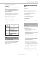
NOTICES NOTICES AMX© 2007, all rights reserved. No part of this publication may be reproduced, stored in a retrieval system, or transmitted, in any form or by any means, electronic, mechanical, photocopying, recording, or otherwise, without the prior written permission of AMX. Copyright protection claimed extends to the AMX AutoPatch Precis hardware and software and includes all forms and matters copyrightable material and information now allowed by statutory or judicial law or here in after granted, including without limitation, material generated from the software programs which are displayed on the screen such as icons, screen display looks, etc. Reproduction or disassembly of embodied computer programs or algorithms is expressly prohibited. No patent liability is assumed with respect to the use of information contained herein. While every precaution has been taken in the preparation of this publication, AMX assumes no responsibility for error or omissions. No liability is assumed for damages resulting from the use of the information contained herein. Further, this publication and features described herein are subject to change without notice. The United States Federal Communications Commission (in 47CFR 15.838) has specified that the following notice be brought to the attention of the users of this product. Federal Communication Commission Radio Frequency Interference Statement: “This equipment generates and uses radio frequency energy and if not installed and used properly, that is, in strict accordance with the manufacturers instructions, may cause interference to radio and television reception. It has been type-tested and found to comply with the limits for a Class B computing device in accordance with the specifications in Subpart J of Part 15 of FCC Rules, which are designed to provide reasonable protection against such interference in a residential installation. However there is no guarantee that interference will not occur in a particular installation. If this equipment causes interference to radio or television reception, which can be determined by turning the equipment off and on, the user is encouraged to try to correct the interference by one or more of the following measures: ä Re-orient the receiving antenna ä Relocate the matrix with respect to the receiver ä Move the matrix away from the receiver ä Plug the matrix into a different outlet so that computer and receiver are on different branch circuits If necessary, the user should consult the dealer or an experienced radio/television technician for additional suggestions. The user may find the booklet, How to Identify and Resolve Radio-TV Interference Problems, prepared by the Federal Communications Commission to be helpful.” This booklet is available from the U.S. Government Printing Office, Washington, D.C. 20402, Stock N. 004-000-00345-4. Use shielded cables. To comply with FCC Class B requirement, all external data interface cables and adapters must be shielded. XNNet is a communication protocol that provides software communications support for Ethernet and Neuron interfaces. Precis, AutoPatch, and XNConnect are trademarks of AMX. TosLink is a registered trademark of the Toshiba Corporation. MS-DOS, Windows, and Windows95 are registered trademarks of Microsoft Corporation. Neuron and LonTalk are registered trademarks of Echelon. Precis Instruction Manual 1 IMPORTANT SAFETY INFORMATION AND INSTRUCTIONS IMPORTANT SAFETY INFORMATION AND INSTRUCTIONS When using and installing your AMX AutoPatch product, adhere to the following basic safety precautions. For more information about operating, installing, or servicing your AMX AutoPatch product see your product documentation. ä Read and understand all instructions before using and installing AMX AutoPatch products. ä Use the correct voltage range for your AMX AutoPatch product. ä There are no user serviceable parts inside an AMX AutoPatch product; service should be done only by qualified personnel. ä If you see smoke or smell a strange odor coming from your AMX AutoPatch product, turn it off immediately and call technical support. ä Turn off and unplug an enclosure before adding or removing boards, unless otherwise specified in that product’s documentation. ä To avoid shock or potential ESD (Electrostatic Discharge) damage to equipment, make sure you are properly grounded before touching components inside an AMX AutoPatch product. ä For products with multiple power supplies in each unit, make sure all power supplies are turned on simultaneously. ä Use surge protectors and/or AC line conditioners when powering AMX AutoPatch products. 2 ä Only use a fuse(s) with the correct fuse rating in your enclosure. ä Make sure the power outlet is close to the product and easily accessible. ä Make sure the product is on or attached to a stable surface. ä Turn off equipment before linking pieces together, unless otherwise specified in that product’s documentation. ä For safety and signal integrity, use a grounded external power source and a grounded power connector. Precis Instruction Manual INFORMATIONS ET DIRECTIVES DE SÉCURITÉ IMPORTANTES INFORMATIONS ET DIRECTIVES DE SÉCURITÉ IMPORTANTES Veuillez respecter les directives de sécurité décrites ci-dessous, lorsque vous installez et utilisez votre appareil AMX AutoPatch. Veuillez consulter la documentation accompagnant l’appareil pour de plus amples informations à propos de l’installation, du fonctionnement ou de la réparation de votre appareil AMX AutoPatch. ä Lisez attentivement toutes les directives avant d’installer et d’utiliser les appareils AMX AutoPatch. ä La tension d’alimentation doit être appropriée pour l’appareil AMX AutoPatch. ä Les appareils AMX AutoPatch ne contiennent aucun composant réparable par l’utilisateur ; toute réparation ne peut être effectuée que par des techniciens qualifiés. ä Si de la fumée ou des odeurs étranges se dégageraient d’un appareil AMX AutoPatch, éteignez-le immédiatement et contactez le Service de support technique. ä Eteignez l’appareil et débranchez-le, avant d’ouvrir le boîtier pour y ajouter ou enlever des cartes électroniques, à moins qu’une instruction dans la documentation de l’appareil n’indique le contraire. ä Assurez-vous que l’appareil soit bien relié à la terre avant de toucher les composantes se trouvant à l’intérieur d’un appareil AMX AutoPatch, pour éviter des décharges électrostatiques pouvant provoquer des dommages à l’équipement. ä Assurez-vous que toutes les unités d’alimentation des appareils dotés d’unités d’alimentation multiples soient allumés simultanément dans chaque unité. ä Servez-vous de protecteurs de surtension ou de conditionneurs de lignes de courant alternatif lorsque vous mettez les appareils AMX AutoPatch sous tension. ä N’utilisez que des fusibles de calibre exact dans les boîtiers. ä Veillez à ce que la prise de courant soit proche de l’appareil et facile à accéder. ä Veillez à ce que votre appareil AMX AutoPatch soit installé sur une surface stable ou qu’il y soit fermement maintenu. ä Fermez tous les composants de l’équipement avant de les connecter, à moins qu’une instruction de cette documentation n’indique le contraire. ä Par mesure de sécurité et pour assurer la qualité des signaux, servez-vous d’une source d’alimentation externe mise à terre et d’un cordon d’alimentation avec mise à terre. Precis Instruction Manual 3 CONTENTS Supplement: Ethernet Connector LEDS CONTENTS Welcome . . . . . . . . . . . . . . . . . . . . . . . . . . . . . . . . . . . . . . . . . . . . . . . . . . . . . . . . . . . . . . . . . . . . . . . . . . . . . . . . 5 Terms to Know . . . . . . . . . . . . . . . . . . . . . . . . . . . . . . . . . . . . . . . . . . . . . . . . . . . . . . . . . . . . . . . . . . . . . . . . . . . . . . . . . . . . . . . . . . . . . . 5 Technical Support . . . . . . . . . . . . . . . . . . . . . . . . . . . . . . . . . . . . . . . . . . . . . . . . . . . . . . . . . . . . . . . . . . . . . . . . . . . . . . . . . . . . . . . . . . . . 5 Installing a Precis Enclosure . . . . . . . . . . . . . . . . . . . . . . . . . . . . . . . . . . . . . . . . . . . . . . . . . . . . . . . . . . . . . . 6 Linking Precis Enclosures . . . . . . . . . . . . . . . . . . . . . . . . . . . . . . . . . . . . . . . . . . . . . . . . . . . . . . . . . . . . . . . . . 8 Introduction to the Precis . . . . . . . . . . . . . . . . . . . . . . . . . . . . . . . . . . . . . . . . . . . . . . . . . . . . . . . . . . . . . . . . 9 Executing and Disconnecting Switches . . . . . . . . . . . . . . . . . . . . . . . . . . . . . . . . . . . . . . . . . . . . . . . . . . . 11 Executing and Disconnecting Switches from the Control Panel . . . . . . . . . . . . . . . . . . . . . . . . . . . . . . . . . . . . . . . . . . . . . . . . . . . 11 Executing and Disconnecting Switches Using BCS Commands . . . . . . . . . . . . . . . . . . . . . . . . . . . . . . . . . . . . . . . . . . . . . . . . . . . 12 Verifying Signal Routing Status (Switches) . . . . . . . . . . . . . . . . . . . . . . . . . . . . . . . . . . . . . . . . . . . . . . . 13 Verifying Signal Status from the Control Panel . . . . . . . . . . . . . . . . . . . . . . . . . . . . . . . . . . . . . . . . . . . . . . . . . . . . . . . . . . . . . . . . . 13 Verifying Signal Status Using BCS Commands. . . . . . . . . . . . . . . . . . . . . . . . . . . . . . . . . . . . . . . . . . . . . . . . . . . . . . . . . . . . . . . . . . 13 Executing Macros . . . . . . . . . . . . . . . . . . . . . . . . . . . . . . . . . . . . . . . . . . . . . . . . . . . . . . . . . . . . . . . . . . . . . . 14 Executing Macros from the Control Panel . . . . . . . . . . . . . . . . . . . . . . . . . . . . . . . . . . . . . . . . . . . . . . . . . . . . . . . . . . . . . . . . . . . . . 14 Executing Macros Using BCS Commands . . . . . . . . . . . . . . . . . . . . . . . . . . . . . . . . . . . . . . . . . . . . . . . . . . . . . . . . . . . . . . . . . . . . . 15 Managing Configuration Files . . . . . . . . . . . . . . . . . . . . . . . . . . . . . . . . . . . . . . . . . . . . . . . . . . . . . . . . . . . . 15 XNConnect. . . . . . . . . . . . . . . . . . . . . . . . . . . . . . . . . . . . . . . . . . . . . . . . . . . . . . . . . . . . . . . . . . . . . . . . . . . . . . . . . . . . . . . . . . . . . . . . . Setting the Password . . . . . . . . . . . . . . . . . . . . . . . . . . . . . . . . . . . . . . . . . . . . . . . . . . . . . . . . . . . . . . . . . . . . . . . . . . . . . . . . . . . . . . . Adding Macros for Local Presets . . . . . . . . . . . . . . . . . . . . . . . . . . . . . . . . . . . . . . . . . . . . . . . . . . . . . . . . . . . . . . . . . . . . . . . . . . . . . Redefining Levels . . . . . . . . . . . . . . . . . . . . . . . . . . . . . . . . . . . . . . . . . . . . . . . . . . . . . . . . . . . . . . . . . . . . . . . . . . . . . . . . . . . . . . . . . . . 15 16 16 17 Adjusting and Checking Volume (Optional Feature) . . . . . . . . . . . . . . . . . . . . . . . . . . . . . . . . . . . . . . . . 19 Adjusting Volume from the Control Panel . . . . . . . . . . . . . . . . . . . . . . . . . . . . . . . . . . . . . . . . . . . . . . . . . . . . . . . . . . . . . . . . . . . . . . 19 Adjusting Volume Using BCS Commands . . . . . . . . . . . . . . . . . . . . . . . . . . . . . . . . . . . . . . . . . . . . . . . . . . . . . . . . . . . . . . . . . . . . . . 20 Checking Volume Status . . . . . . . . . . . . . . . . . . . . . . . . . . . . . . . . . . . . . . . . . . . . . . . . . . . . . . . . . . . . . . . . . . . . . . . . . . . . . . . . . . . . . 22 Adjusting and Checking Input Gain (Optional Feature). . . . . . . . . . . . . . . . . . . . . . . . . . . . . . . . . . . . . . 23 Locking and Unlocking the Control Panel . . . . . . . . . . . . . . . . . . . . . . . . . . . . . . . . . . . . . . . . . . . . . . . . . . 23 BCS (Basic Control Structure) Commands . . . . . . . . . . . . . . . . . . . . . . . . . . . . . . . . . . . . . . . . . . . . . . . . 24 AMX Limited Warranty and Disclaimer . . . . . . . . . . . . . . . . . . . . . . . . . . . . . . . . . . . . . . . . . . . . . . . . . . 26 Software License and Warranty Agreement . . . . . . . . . . . . . . . . . . . . . . . . . . . . . . . . . . . . . . . . . . . . . . 27 Precis Specifications. . . . . . . . . . . . . . . . . . . . . . . . . . . . . . . . . . . . . . . . . . . . . . . . . . . . . . . . . . . . . . . . . . . . 29 4 Precis Instruction Manual WELCOME WELCOME Welcome to the Precis User’s Operation Manual. This manual contains quick, easy-to-follow instructions for operating a Precis™ Distribution Matrix from the Control Panel and from a serial control device that supports BCS (Basic Control Structure) commands. This document does not include any detailed information about SBCs (Single Bus Controllers) or remote control panels for the Precis. Call technical support for more information about these controller types (see “Technical Support” on this page). TERMS TO KNOW BCS (Basic Control Structure) BCS is a set of alphanumeric characters that combine to form command lines. Use BCS command lines to control a system from any serial device that connects to the serial connector on the enclosure and allows you to enter characters – such as a PC (personal computer). BCS commands are a subset of the XNNet communications protocol. Control Panel A Control Panel (optional) is attached to an enclosure and is designed for controlling a Precis Distribution Matrix. Level A level is a set of signals that usually switch together; for example, a stereo audio level could be comprised of left and right audio signals that usually switch together. Macro A macro is a predetermined set of switches that always occur together. Executing a macro is a shortcut for executing that set of switches. Signal A signal can be analog audio, analog video, serial digital, sync information, or other types. A source or destination signal (also called input and output signals) can be comprised of a set of connectors whose signals switch together, such as an “RGBHV” signal. To route a specific source signal to a specific destination, the source and destination must be the same signal type and must reside in the same level. Source and Destination Connectors Source and destination connectors are on the rear of an enclosure. Source and destination signal cables attach to the source and destination connectors. Standard Precis audio connectors are 5-position screw terminal block; video connectors are BNC. Switch A switch is an active connection between a source signal and one or more destinations. XNNet XNNet is a communication protocol which provides software communications support for AMX AutoPatch products as well as other products manufactured by AMX. It includes several subsets, one of which is the BCS command set used by the Precis series™. The XNNet protocol supports a wide variety of physical interfaces, such as standard serial RS232, Ethernet, LonTalk®, Neuron®, and others. TECHNICAL SUPPORT Before contacting technical support with a question, please consult this manual. If you still have questions, contact your AMX representative or technical support. Have your serial number (normally located on the rear of the enclosure) ready. We recommend recording the serial number in an easily accessible location. AMX Contact Information ä 3000 Research Drive, Richardson, TX 75082 ä 800.222.0193 ä 469.624.8000 ä Fax 469.624.7153 ä Technical Support 800.932.6993 ä www.amx.com Precis Instruction Manual 5 INSTALLING A PRECIS ENCLOSURE INSTALLING A PRECIS ENCLOSURE Balanced Audio Unbalanced Audio + – + – + – + – Left Right Left Right Precis enclosures are designed to fit in a standard EIA 19 in (48.26 cm) rack. Each enclosure comes with the following items in the box: q Enclosure q Precis User’s Operation Manual q Power Cord 5-position, screw terminal audio connectors the Precis enclosure in a rack and fasten with mounting screws. Ê Place Optical and coaxial connectors all source and destination cables Ë Attach (types of connectors vary according to model). Note: Digital optical (TosLink® compatible) and digital coaxial (S/PDIF compatible) inputs switch only to digital optical and digital coaxial outputs. a null modem serial cable (pinout on Ì Attach next page) and the power cord (plugging in the power cord turns on the enclosure). Make sure the power outlet is close to the enclosure and is easily accessible. X Net cable (for X Net accessories) N N Serial cable BNC connectors Ethernet cable (for linking enclosures) Power cord CPU connections vary according to model 6 Precis Instruction Manual INSTALLING A PRECIS ENCLOSURE External Control Serial Port Settings Baud Rate 9600 Data Bits 8 Stop Bits 1 Parity None RS-232 Pinout – All Precis Models Use a null modem cable that matches the pinout diagram below for RS-232 without hardware flow control. AMX AutoPatch equipment requires pins 2, 3, and 5 only. PC: DB-9 AMX AutoPatch: DB-9 PC: DB-9 AP: DB-9 #5 GND ----------- #5 GND #2 RXD ------------- #3 TXD #3 TXD ------------ #2 RXD No hardware flow control Optional RS-232 Pinout with Hardware Flow Control – Precis 500 MHz Only Use a null modem cable that matches the pinout diagram below for RS-232 with hardware flow control on the Precis 500 MHz. PC: DB-9 AMX AutoPatch: DB-9 PC: DB-9 AP: DB-9 #5 GND ----------- #5 GND #2 RXD ----------- #3 TXD #3 TXD ------------ #2 RXD #7 RTS --------- #8 CTS #8 CTS ------------ #7 RTS #6 DSR /#4 DTR Hardware flow control sure the enclosure is working properly Í Make by executing a switch (see “Executing and Disconnecting Switches” on page 11). If the enclosure is not working properly, contact technical support (see page 5). Precis Instruction Manual 7 LINKING PRECIS ENCLOSURES LINKING PRECIS ENCLOSURES two enclosures using crossover cable A Link l (or network cable with a crossover adapter). This section applies specifically to Precis models with 32-bit processors and Ethernet link connectors. In a multi-enclosure system with an external controller, the enclosure connected to the control device receives all control information and relays it via the links to the other enclosures. A Precis with an Ethernet connector can have a virtually unlimited number of linked enclosures. Note: If any linked enclosures were not in the original system, a new configuration file is needed (call technical support; see page 5). three or more enclosures using network l B Link cable and a HUB. 10/100 HUB 100 MBPS 10 MBPS 8 Precis Instruction Manual INTRODUCTION TO THE PRECIS INTRODUCTION TO THE PRECIS Use Switch mode to execute switches, Status mode to verify signal status, and Macro mode to execute a macro. If the optional Volume Adjust mode is available, use the Volume Adjust (Status) key, Up Arrow (Macro) key, and Down Arrow (Lock) key to adjust volume. The Precis is available in an 8x4 or 12x8 (some models also come in 8x8) configuration with a variety of control and connector options. A Precis Control Panel works in three standard modes: Switch (default), Status, and Macro. Level keys Activates levels for switches or status inquiries, also used for entering macros and the password Macro key Places the Control Panel in execute Macro mode Up Arrow key (optional) Increases volume Lock key Locks and unlocks Control Panel operations (password required) Volume Adjust FGP37-1208-547 Down Arrow key (optional) Decreases volume Status key Places the Control Panel in Status mode Cancel key Destination keys Cancels an incomplete command and returns the Control Panel to Switch mode Selects a destination on the selected level, also used for entering macros Source keys Volume Adjust key (optional) Places audio in Volume Adjust mode Source connectors Selects a source on the specified level, also used for entering macros Connection point for source signal cables N X Net Link connectors* N Connection point for X Net controllers and for linking other enclosures Serial connector Connection point for RS232 serial devices FGP37-1208-547 Fuse 5 mm x 20 mm 250 V 1 amp Destination connectors Power connector Attachment point for power cable Precis Instruction Manual Connection point for destination signal cables 9 INTRODUCTION TO THE PRECIS Source connectors Connection point for source signal cables Status Indicator** Status light for system N X Net Link connector* N Connection point for X Net compatible accessories Serial connector Connection point for RS232 serial devices FG1037-60 Ethernet Link connector** Power connector Connection point for linking additional enclosures Attachment point for power cable Destination connectors Connection point for destination signal cables Source connectors Connection point for source signal cables N X Net Link connector* N Connection point for X Net compatible accessories Serial connector Connection point for RS232 serial devices FG1037-66 Fuse Power connector 5 mm x 20 mm 250 V 1 amp Attachment point for power cable *The XNNet Link connector will be single or double depending on the Precis model. **This feature is not available on all Precis models. 10 Precis Instruction Manual Destination connectors Connection point for destination signal cables EXECUTING AND DISCONNECTING SWITCHES EXECUTING AND DISCONNECTING SWITCHES To execute/disconnect a switch: 1. Press a Level key to select a level. The Level key illuminates. If you do not select a level, the system executes or disconnects the switch on the level associated with the farthest left Level button (the default level for that key is video and audio). A switch is an active connection between a source signal and one or more destination devices. Before executing or disconnecting a switch on the Control Panel, make sure the panel is in Switch mode. You can execute and disconnect switches from the following: ä The Control Panel ä An external serial controller (computer, AMX, Crestron, etc.) via BCS (Basic Control Structure) commands ä A Single Bus Controller (only executes switches) 2. The Source key flashes, and after a moment any destinations to which that signal is already routed illuminate. The flashing key is the “hot” source; all other commands center around that source until you change mode, level, or select a different source. 3 Before executing or disconnecting a switch from the Control Panel, make sure the panel is in Switch mode. If you are unsure which mode the Control Panel is in, press the Cancel key - all the lights on the Control Panel turn off, and the Control Panel reverts to Switch mode. Follow the instructions (to the right) to execute and disconnect switches. Press a Destination key(s) to select a destination(s). Selecting (illuminating) a disconnected (unlit) Destination key executes a switch; deselecting a connected (lit) Destination key disconnects a switch. Single Bus Controllers are not covered in this document. EXECUTING AND DISCONNECTING SWITCHES FROM THE CONTROL PANEL Press a Source key to select a source. Note: Although our instructions direct you to select a source first, you may execute and disconnect switches by selecting the destination before selecting the source. When you select the destination, the key flashes and is the “hot” destination. All other commands center around that destination until you change mode, level or select another destination. Only one source signal can be routed to a single destination. Precis Instruction Manual 11 EXECUTING AND DISCONNECTING SWITCHES DISCONNECTING SWITCHES EXECUTING AND DISCONNECTING SWITCHES USING BCS COMMANDS You can use BCS with a device that connects to the serial connector on the Precis CPU. BCS commands are a subset of the XNNet communications protocol. EXECUTING SWITCHES To execute a switch, enter the command using the following command line format (where “#” represents any valid level, source, or destination number). CL#I#O#T or CL#O#I#T To disconnect a switch, enter the command using the following command line format (where “#” represents any valid level, source, or destination number). To disconnect a source from all destinations, use the second format. DL#O#T or DL#I#T To cancel an incomplete BCS command, enter the “X” command at any time. Examples: To cancel an incomplete BCS command, enter the “X” command at any time. BCS Command Examples: DL1O6T BCS Command Action CL0I6O2T Switches source 6 to destination 2 on Level 0 (default is audio and video) CL1I6O2 4T Switches source 6 to destinations 2 and 4 on Level 1 (default is video only) CL2O2I5T Switches source 5 to destination 2 on Level 2 (default is audio only) CL2I6X Cancels the incomplete command Note: You can enter multiple destinations in each execute switch command by including a space between each destination number, but you can enter only one source signal and only one level. 12 Action Disconnects destination 6 on Level 1 (default is video only) DL1I2 4T Disconnects sources 2 and 4 from all destinations that are receiving that signal on Level 1 (default is video only) DL2I6X Cancels the incomplete command Note: You can enter multiple sources and destinations in each disconnect switch command by including a space between each number, but you can enter only one level. See “BCS (Basic Control Structure) Commands” on page 25 for a complete list of the BCS command characters. Precis Instruction Manual VERIFYING SIGNAL ROUTING STATUS (SWITCHES) VERIFYING SIGNAL ROUTING STATUS (SWITCHES) 3. Verify the routing status of signals to confirm that switches are executing properly. Press a Source or Destination key to select a source or destination. If you pressed a Source key, that key illuminates and the Destination keys show the routing status of the signal. If no Destination keys illuminate, the signal is not routed or is not available on that level. If you pressed a Destination key, a Source key illuminates, showing which input source is currently routed to that destination. If no Source key illuminates, the signal is not routed or is not available on that level. You can verify signal status from the following: ä The Control Panel ä An external serial controller (computer, AMX, Crestron, etc.) via BCS (Basic Control Structure) commands VERIFYING SIGNAL STATUS FROM THE CONTROL PANEL You can put the Control Panel in Status mode by pressing the Status key. The Control Panel remains in Status mode (with the Status key illuminated) until you press the Cancel or Status key. While in Status mode, you can select different Levels, Sources, and Destinations at any time without affecting signal routing. To verify signal status using the Control Panel: 1. Press the Status key to put the Control Panel in Status mode. The Status key illuminates and all other lights on the Control Panel turn off. 2. Press a Level key to select a level. The Level key illuminates. If you do not select a level, the system uses the level associated with the farthest left Level key (default is audio and video). 4. Press the Status key or Cancel key to return to Switch mode. The Status, Source, and Destination keys turn off, and the Control Panel returns to Switch mode. VERIFYING SIGNAL STATUS USING BCS COMMANDS You can use BCS commands with a device that connects to the serial connector on the Precis CPU. To verify signal routing status, enter the command using the following command line format (where “#” represents any valid level, source, or destination number). SL#O#T or SL#I#T To cancel an incomplete BCS command, enter the “X” command at any time. Precis Instruction Manual 13 EXECUTING MACROS EXECUTING MACROS FROM THE CONTROL PANEL Examples: BCS Command Action SL0O4T Returns the status for destination 4 on Level 0 (default is audio and video) SL2I4T Returns the status for source 4 on Level 2 (default is audio only) SL1O7X Cancels the incomplete command The Control Panel must be in Macro mode to execute a macro. Once you have selected a macro, the Control Panel returns to Switch mode. Put the Control Panel in Macro mode again to execute another macro. To execute a macro using the Control Panel: 1. Press the Macro key to put the Control Panel in Macro mode. The Macro key flashes, and all other lights on the Control Panel turn off. When the Macro key starts flashing, you have 10 seconds to enter the macro before the Control Panel reverts to Switch mode. See “BCS (Basic Control Structure) Commands” on page 25 for a complete list of the BCS command characters. EXECUTING MACROS 2. A macro is a predetermined set of switches that always occur together (for example, you may have the most commonly executed switches set as macros). Executing a macro is a shortcut for executing that set of switches. A 12x8 Precis enclosure can store up to 160 macros, and an 8x4 enclosure can store up to 96 macros. To program new macros, see page 16. The Level key illuminates. 3. The Control Panel ä An external serial controller (computer, AMX, Crestron, etc.) via BCS (Basic Control Structure) commands 14 Press a Source or Destination key to select a macro. Each key is assigned a different macro. The Macro key stops flashing, the macro is executed, and the Control Panel returns to Switch mode. All Control Panel lights are off. You can execute a macro from the following: ä Press a Level key to select the level where the macro resides. 4. Precis Instruction Manual Repeat steps 1 through 3 for each macro you want to execute. MANAGING CONFIGURATION FILES EXECUTING MACROS USING BCS COMMANDS MANAGING CONFIGURATION FILES You can use BCS commands with a device that connects to the serial connector on the Precis CPU. BCS commands are a subset of the XNNet communications protocol. To execute a macro, enter the command using the following command line format (where “#” represents any valid macro number). RL#P#T or RL#P# #T To cancel an incomplete BCS command, enter the “X” command at any time. Examples: BCS Command Executes macro 2 on Level 1 (default is video only) RL2P1 2T Executes macros 1 and 2 on Level 2 (default is audio only) RL8PX XNConnect is a graphical software program (with a Help file) that can display your most recent configuration and allows you to: ä Set the password ä Add macros for local presets ä Redefine levels XNConnect can also download the modified file to the system. Note: Use this software only if you need to change the configuration from the original specification. Action RL1P2T XNCONNECT To install XNConnect: 1. Close all other applications currently running on your PC. 2. Insert the AMX AutoPatch CD into your CD drive to automatically start. If the CD does not autorun, explore the CD folders and double-click the menu.pdf. 3. Follow the directions in subsequent dialogs in the installation program. 4. Review the Readme.txt file found on CD:\APConfig\ or after installation in the main installation folder. The default location is C:\AutoPtch\Configuration Software <Version>. Cancels the incomplete command Note: In each execute macro command, you can enter multiple macros by including a space between each macro number. See “BCS (Basic Control Structure) Commands” on page 25 for a complete list of the BCS command characters. * If you cannot locate your system’s AMX AutoPatch CD, have your serial number ready and contact technical support. Precis Instruction Manual 15 MANAGING CONFIGURATION FILES To launch XNConnect, open the configuration file and connect the enclosure for downloading configuration information: 1. From the Start menu, select Programs. 2. Select AutoPatch Applications (or any other file group you selected during the install). 4. Enter a single digit between zero and seven in each field. 5. Check the box for Configure password immediately. Click OK. ADDING MACROS FOR LOCAL PRESETS 3. Select the XNConnect group. 4. Select the XNConnect program. If your Precis firmware (embedded software) version is earlier than Version 1.4.1, contact AMX for conditions that apply to programming macros for presets. 5. Open your configuration file found in the C:\AutoPtch\Configuration Software <Version>\MyXCL folder. To discern your firmware version: 1. Follow the steps for launching XNConnect (see page 16). 6. Make a duplicate copy of your .xcl file with a new unique name using Save As. [We strongly recommend this optional step.] 2. From the File menu, select Discover Hardware only. 7. Connect the enclosure to your PC via the communication ports.** 3. Select the enclosure on the tree in the left pane. 4. Click the Network tab in the right pane to display the CPU Firmware version number. **If your PC does not use Com 1, after step 4 open the Communication menu, select the appropriate communication link, select Change Comm Settings, and make necessary changes. SETTING THE PASSWORD For information on using the password to lock and unlock the control panel, see page 23. The following steps use as an example the construction of macro #1 (ConfRm1) that connects level 0, input 1 to output 4 and input 2 to outputs 2 and 3. To set a front panel password: 1. Follow the steps for launching XNConnect. To add macro (preset) information to the configuration file: 1. Follow the steps for launching XNConnect (see page 16). 2. 2. In the Virtual Matrices view, right click the level 0 (first) virtual matrix and select Manage Local Presets (see the next graphic). 3. Click the Name New button; enter the name ConfRm1. (Description is optional.) Click OK. 3. 16 In the Hardware View, right click the appropriate front panel icon. (Double-click the Precis first if the front panel icon is not displayed.) Select Set Password. Precis Instruction Manual MANAGING CONFIGURATION FILES The system is now ready to execute the macro (preset) using either the Control Panel or BCS commands. REDEFINING LEVELS Name New 4. Modify Preset Click the Modify Preset button. The Modify Preset dialog appears (see the next graphic). XNConnect can be used to redefine levels (virtual matrices). The following steps provide the example of configuring the RGB connectors on a 12x8 Precis to switch Y/c and composite signals by modifying existing (default) virtual matrices (levels). 5. Select Source Channel 1 and Destination Channel 4; click the Assign Switch button. To reconfigure RGB connectors to switch Y/c and composite: 1. Follow the steps for launching XNConnect (see page 16). 6. Select Source Channel 2 and Destination Channels 2 and 3 (hold the Ctrl key when multi-selecting); click Assign Switch. 2. In the Virtual Matrix view, right click the Red virtual matrix and select delete. Repeat with the Green virtual matrix. 3. From the Add menu, select Virtual Matrix. The Assign Virtual Matrix Signals dialog appears. Source Channels Assign Switch Destination Channels Standard Basic Tab Name Field Assign Signal(s) 7. Click OK. 4. Type Y/c in the Name field. 8. From the Configure menu, select Configure All VM Local Presets. 5. Click the Standard Basic tab. From its list, select R and click the Assign Signal(s) Precis Instruction Manual 17 MANAGING CONFIGURATION FILES button; repeat with G and click OK. The Assign Signals to Matrices dialog appears. 8. Click the Group by Pattern button. The Group Connectors by Pattern dialog Spanning Matrix Sources Only Destinations Only Assign Matrix 6. Select Matrix 1 under Matrix for R and click the Assign Matrix button. Select Matrix 2 for G and click Assign Matrix. Click OK. 7. In the left pane, right click the newly created Y/c virtual matrix and select Manage Connector Groupings. The Manage Virtual Matrix Groupings dialog appears. Assign Signal Number of Channels to Create appears. 9. Group by Pattern Click the Spanning and Sources Only radio buttons in the Pattern Definition group. 10. Select 6 in the Number of Channels to Create field and click the Assign Signal button twice, accepting the default connector numbers. This assigns 6 channels to R for the Y signal and 6 to G for the c channel. Click OK. Accept Assignments 11. Repeat steps 8 through 10, clicking Destinations Only instead of Sources Only and selecting 4 channels instead of 6. Click OK. 12. Click the Accept Assignments button. 18 Precis Instruction Manual ADJUSTING AND CHECKING VOLUME (OPTIONAL FEATURE) 13. Repeat steps 2 through 12 with the following modifications to create a “composite signal” virtual matrix. Step 2: Delete the Blue Only virtual matrix. Step 4: Type Composite in the Name field. Step 5: Select B. Step 6: Select Matrix 3. Step 10: Select 12 channels. Step 11: Select 8 channels. 14. From the Configure menu, select the Configure All command. The system is now ready to switch Y/c signals on level 3 and composite signals on level 4 using either the Control Panel (fourth and fifth level buttons respectively) or BCS commands. Follow the instructions to adjust the volume using the increment/decrement method (volume is increased or decreased by 1 dB below –30 dBu and 0.5 dB above). To adjust volume using the Increment/Decrement method: 1. Press and hold the Volume Adjust (Status) key for at least 2 seconds, until it illuminates and then flashes to indicate that the control panel is in Volume Adjust mode. 2. Press a Destination key(s) to select the output(s) that needs volume adjustment. The Destination key(s) illuminates, along with the Up Arrow (Macro) and Down Arrow (Lock) keys. Note: For more information on redefining levels, see the XNConnect Help file. 3. ADJUSTING AND CHECKING VOLUME (OPTIONAL FEATURE) Press and release the Up Arrow (Macro) key to increase the volume or the Down Arrow (Lock) key to decrease the volume. The pressed key flashes and then stays illuminated. If your system has the Volume Control option, you can adjust volume from the following: ä Control Panel 4. ä An external controller (computer, AMX, Crestron, etc.) via BCS (Basic Control Structure) commands Repeat step three until the desired volume level is reached. 5. Press the Cancel key to return to the Switch (default) mode. You can check volume status only from an external controller via BCS commands. ADJUSTING VOLUME FROM THE CONTROL PANEL Note: Pressing the Cancel key does not cancel any of the volume adjustments that were just entered. Before adjusting the volume, check to be sure the panel is in Switch mode. If you are unsure which mode the Control Panel is in, press the Cancel key – all the lights on the Control Panel turn off, and the Control Panel reverts to Switch mode. Precis Instruction Manual 19 ADJUSTING AND CHECKING VOLUME (OPTIONAL FEATURE) ADJUSTING VOLUME USING BCS COMMANDS To cancel an incomplete BCS command, enter the “X” command at any time. You can use BCS with an external controller that connects to the serial connector on the Precis CPU. BCS commands are a subset of the XNNet communications protocol. Adjusting volume can be done using any of the following four methods. ä ä ä ä Absolute – adjusts the volume to a specific decibel level Relative – increases the volume a specific decibel amount Increment/Decrement – increases or decreases the volume a step Examples: BCS Command CL0O3VA100T Adjusts volume to 10.0 dB for Level 0, destination 3 CL0O6 7VA50T Adjusts volume to 5.0 dB for Level 0, destinations 6 and 7 CL0O2VA-250T Adjusts volume to –25.0 dB for Level 0, destination 2 CL0O7VA2X Mute/Un-mute (Optional Feature) – applies or removes mute to volume Note: Volume adjustments are made on an audio level and will remain in effect if you then switch the output(s) on an audio follow video level. ADJUSTING VOLUME – ABSOLUTE METHOD You can use the Absolute method to adjust the volume of a destination signal to a specific decibel level that is defined in relationship to the input level. To adjust volume using the Absolute method, enter the command using the following command line format (where “#” represents any valid audio level or destination number and “^^^” represents the specific decibel level you want). The decibel level is specified as a decimal number to the tenth place without the decimal marker; for example, enter 100 for a decibel level of +10.0 or enter –35 for a decibel level of –3.5. The decimal number must be between –70.0 and 10.0. Cancels the incomplete command Note: You can enter multiple destinations in each Absolute Volume command by including a space between each destination number, but you can enter only one level per command line. ADJUSTING VOLUME – RELATIVE METHOD You can use the Relative method to adjust the volume of a destination signal by a specific amount. To adjust volume using the Relative method, enter the command using the following command line format (where “#” represents any valid audio level or destination number and “^^^” represents the specific increase or decrease in decibel level that you want). The amount is specified as a decimal number to the tenth place without the decimal marker; for example, enter the digits 25 for an increase in the decibel level of +2.5 or enter –250 for a decrease in the decibel level of –25.0 The decimal number must be between –70.0 and 10.0. CL#O#VR^^^T CL#O#VA^^^T 20 Action Precis Instruction Manual ADJUSTING AND CHECKING VOLUME (OPTIONAL FEATURE) To cancel an incomplete BCS command, enter the “X” command at any time. To cancel an incomplete BCS command, enter the “X” command at any time. Examples: Examples: BCS Command Action BCS Command CL0O3VR60T Increases volume by 6.0 dB for Level 0, destination 3 CL0O3VS+T Increases volume a step for Level 0, destination 3 CL0O1 2VR-60T Decreases volume by –6.0 dB for Level 0, destinations 1 and 2 CL0O5 6VS+T Increases volume a step for Level 0, destinations 5 and 6 CL0O2VS-T Decreases volume a step for Level 0, destination 2 CL0O4 8VS-T Decreases volume a step for destinations 4 and 8 CL0O5VR-120T CL0O7VX Decreases volume by –12.0 dB for Level 0, destination 5 Cancels the incomplete command CL0O7VSX Note: You can enter multiple destinations in each Relative Volume command by including a space between each destination number, but you can enter only one level per command line. ADJUSTING VOLUME – INCREMENT/DECREMENT METHOD You can use the Increment/Decrement method to increase or decrease the volume of a destination signal a step (volume is increased or decreased by 1 dB below –30 dBu and 0.5 dB above). You may need to repeat the command to hear an audible difference. To adjust volume using the Increment/Decrement method, enter the command using the following command line format (where “#” represents any valid audio level or destination number and “S+” and “S-” represent a step of increase or decrease, respectively, in volume). Action Cancels the incomplete command Note: You can enter multiple destinations in each Increment/Decrement Volume command by including a space between each destination number, but you can enter only one level per command line. APPLYING/REMOVING MUTE (OPTIONAL FEATURE) If your system has the Mute option, you can apply and remove the mute to the volume using BCS commands. Removing the mute returns a destination to its previous un-muted volume level. To mute the volume, enter the command using the following command line format (where “#” represents any valid audio level or destination number). CL#O#VMT CL#O#VS+T or CL#O#VS-T Precis Instruction Manual 21 ADJUSTING AND CHECKING VOLUME (OPTIONAL FEATURE) CHECKING VOLUME STATUS Examples: BCS Command You can check volume status only from an external controller via BCS commands. Action CL0O2VMT Mutes volume for Level 0, destination 2 CL0O1 4VMT Mutes volume for Level 0, Destinations 1 and 4 To remove the mute, enter the command using the following command line format (where “#” represents any valid audio level or destination number). CL#O#VUT To check the volume status for a specific destination, enter the command using the following command line format (where “#” represents any valid audio level or destination number). The decibel level in the result of the status check is specified as a decimal number to the tenth place without the decimal marker; for example if the result is –480, the decibel level is –48.0 or if the result is 48, the decibel level is +4.8. SL#O#VAT Tip: This command is easy to remember if you think of the “VU” as “volume un-mute.” To cancel an incomplete BCS command, enter the “X” command at any time. Examples: Examples: BCS Command Action CL0O3VUT Removes mute for Level 0, destination 3 BCS Command CL0O6 7VUT Removes mute for Level 0, destinations 6 and 7 SL0O3VAT Checks volume status SL0O3VAT( 35 ) for Level 0, destination 3 [+3.5 dB] SL0O8VAT Checks volume status SL0O8VAT( 5 ) for Level 0, destination 8 [+0.5 dB] SL0O2VAT Checks volume status SL0O2VAT( –125 ) for Level 0, destination 2 [-12.5 dB] Note: When a Mute command is followed by any other volume command, other than un-mute, the volume returns to its previous un-muted state before the new command is applied. For example, if destination 1 was set at 5 dB and a mute command was entered (CL0O1VMT), and then later an Increment command (CL0O1VS+T) was entered, the result would be a volume level of 5.5 dB. 22 Action Result Note: You cannot enter multiple levels or destinations in Volume Status commands. Precis Instruction Manual ADJUSTING AND CHECKING INPUT GAIN (OPTIONAL FEATURE) ADJUSTING AND CHECKING INPUT GAIN (OPTIONAL FEATURE) ä Control Panel – select a Source (input) key instead of a Destination (output) key. ä BCS Commands – substitute an “I” (input) for the “O” (output) in the command line. If your system has the Volume Control option, it also supports the Input Gain Control option. Caution: We recommend that input gain adjustments be made only by a qualified dealer. The purpose of Precis “Input Gain Control” is to allow source (input) signals of various amplitudes to be equalized before they are routed and the volume is adjusted. Equalizing source levels provides a consistent reference for volume adjustments and eliminates level jumps when routing a new source to a destination. Typical uses for input gain (the nominal level of the signal from the source device) include switching consumer and professional grade audio equipment (whose levels can vary noticeably) in the same matrix switcher and for equalizing amplitudes between balanced and unbalanced source inputs. To use the “Input Gain Control” feature to equalize input levels: 1. Route a source (input) to the first destination (output). 2. Adjust the input gain for the source to a specific dB level. 3. Repeat for all sources that will be routed to the same destination. You can adjust input gain and check its status by modifying the instructions in the previous section, “Adjusting and Checking Volume,” as follows: The range of input gain adjustment is from +10 to –10 decibels. LOCKING AND UNLOCKING THE CONTROL PANEL Disable Control Panel operations to prevent accidental switches and macros by locking the Control Panel. When the Control Panel is locked, the Lock key is illuminated, and you are unable to use the Control Panel for any operations other than unlocking the panel. While the Control Panel is locked, BCS commands still work. Use the password that came with your system (the default password from the factory is the first five Level keys, going left to right) to lock and unlock the Control Panel; you cannot lock or unlock the panel using BCS commands. To change your password, see page 16. After you press the Lock key, you have 10 seconds to enter the password before the Control Panel reverts to its previous mode (locked or Switch mode). If you enter the wrong password, press the Lock key again and enter the correct password. To lock/unlock the Control Panel: 1. Press the Lock key to put the Control Panel in Lock mode. The Lock key flashes (for only 10 seconds), and all other lights on the Control Panel turn off. You must enter the password while the Lock key is flashing. Precis Instruction Manual 23 BCS (BASIC CONTROL STRUCTURE) COMMANDS 2. While the Lock key is flashing, enter the enclosure’s password (the default password from the factory is the first five Level keys, going left to right). If you locked the Control Panel, the Lock key light stops flashing and shines constant; all other lights on the Control Panel turn off. If you unlocked the Control Panel, the Lock key light turns off and the panel is in Switch mode. BCS (BASIC CONTROL STRUCTURE) COMMANDS BCS is a set of alphanumeric characters that allow a PC or other control device to send commands to your Precis through the serial connector (on the CPU). To establish communication between your PC (personal computer) and your Precis, attach the PC to the serial connector and use terminal emulation software (such as Windows95 HyperTerminal). BCS commands are a subset of the XNNet communications protocol. Command Line Formats To generate commands, enter them using the following formats in which “#” represents any valid level, local preset, input, or output number and “^^^” represents a decimal number to the tenth place without the decimal marker (for example, 100 = 10.0 and 35 = 3.5). O is the letter O, not the number zero (0). q To execute a switch: CL#I#O#T or CL#O#I#T q To verify switch status: SL#O#T or SL#I#T q To execute a local preset: RL#P#T q To disconnect a switch: DL#O#T or DL#I#T q To adjust absolute volume*: CL#O#VA^^^T q To adjust relative volume*: CL#O#VR^^^T q To adjust increment/decrement volume*: CL#O#VS+T or CL#O#VS-T q To apply volume mute*: CL#O#VMT q To apply volume un-mute*: CL#O#VUT *To use these commands your system must contain audio boards with Volume Adjustment capability. In addition, the mute and un-mute commands require a Precis with a 32-bit CPU. If the command specifies a decimal number, the number must fall within the adjustment range for the specific type of audio board. For multiple outputs or multiple local presets, enter a space between each number. 24 Precis Instruction Manual BCS (BASIC CONTROL STRUCTURE) COMMANDS The table below shows BCS command characters (keys), their functions, and short descriptions of their functions. Key Function Description C Change Initiates an execute switch command; this must precede the source and destination specifications D Disconnect Initiates a disconnect switch command; this must precede the source and destination specifications Flags the next 1- to 2- digit number as a level number Default settings are: Level 0 - Audio and Video Level 1 - Video only Level 2 - Audio only L Level “0” - “9” Number I Input O Output Flags the next 1- to 2- digit number as an output specification Note: O is the letter O, not the number zero (0) “ ” Space Separates numbers in multiple number entries T Take Executes a command X Exit Exits, or cancels, the command being entered S Status Initiates verification of the status of input and output connections R Macro Initiates an execute global macro or execute local macro command Note: Global macros are not implemented at this time P Macro Number VA Volume Absolute Flags the next 1 - 3 digit number as the volume adjustment to a specific decibel level VR Volume Relative Flags the next 1 - 3 digit number as the volume adjustment of a specific decibel amount VS+ or VS- Volume Step Increment/Decrement Adjusts volume of a specified output up or down a step VM or VU Volume Mute/Un-mute Applies or removes mute to the volume Identifies inputs, outputs, macros, and levels; combine the digits to form larger numbers Flags the next single digit number as an input specification Flags the next 1- to 2- digit number as a local macro number Precis Instruction Manual 25 AMX LIMITED WARRANTY AND DISCLAIMER AMX LIMITED WARRANTY AND DISCLAIMER All products returned to AMX require a Return Material Authorization (RMA) number. The RMA number is obtained from the AMX RMA Department. The RMA number must be clearly marked on the outside of each box. The RMA is valid for a 30-day period. After the 30-day period the RMA will be cancelled. Any shipments received not consistent with the RMA, or after the RMA is cancelled, will be refused. AMX is not responsible for products returned without a valid RMA number. ä The AMX Authorized Partner must contact AMX Technical Support to validate the failure before pursuing this service. ä Non-warranty repair is a billable service. ä Products repaired under this policy will carry a ninety (90) day warranty on material and labor. ä AMX will notify the AMX Authorized Partner with the cost of repair, if cost is greater than the Standard Repair Fee, within five (5) days of receipt. ä The AMX Authorized Partner must provide a Purchase Order or credit card number within five (5) days of notification, or the product will be returned to the AMX Authorized Partner. ä The AMX Authorized Partner will be responsible for in-bound and out-bound freight expenses. ä Products repaired will carry a ninety (90) day warranty or the balance of the remaining warranty, whichever is greater. Products will be repaired within ten (10) business days after AMX Authorized Partner approval is obtained. ä Products that are returned and exhibit signs of damage or unauthorized use will be processed under the Non-Warranty Repair Policy. Non-repairable products will be returned to the AMX Authorized Partner with an explanation. ä See AMX Non-Warranty Repair Price List for minimum and Standard Repair Fees and policies. AMX will repair any defect due to material or workmanship issues during the applicable warranty period at no cost to the AMX Authorized Partner, provided that the AMX Authorized Partner is responsible for in-bound freight and AMX is responsible for out-bound ground freight expenses. The AMX Authorized Partner must contact AMX Technical Support to validate the failure before pursuing this service. ä AMX will complete the repair and ship the product within five (5) business days after receipt of the product by AMX. The AMX Authorized Partner will be notified if repair cannot be completed within five (5) business days. ä 26 Non-Warranty Repair Policy Products that do not qualify to be repaired under the Warranty Repair Policy due to age of the product or Condition of the product may be repaired utilizing this service. ä ä AMX will continue to provide Warranty Repair Services for products discontinued or replaced by a Product Discontinuance Notice. ä Warranty Repair Policy ä ä Precis Instruction Manual SOFTWARE LICENSE AND WARRANTY AGREEMENT SOFTWARE LICENSE AND WARRANTY AGREEMENT ä LICENSE GRANT. AMX grants to Licensee the non-exclusive right to use the AMX Software in the manner described in this License. The AMX Software is licensed, not sold. This license does not grant Licensee the right to create derivative works of the AMX Software. The AMX Software consists of generally available programming and development software, product documentation, sample applications, tools and utilities, and miscellaneous technical information. Please refer to the README.TXT file on the compact disc or download for further information regarding the components of the AMX Software. The AMX Software is subject to restrictions on distribution described in this License Agreement. AMX Dealer, Distributor, VIP or other AMX authorized entity shall not, and shall not permit any other person to, disclose, display, loan, publish, transfer (whether by sale, assignment, exchange, gift, operation of law or otherwise), license, sublicense, copy, or otherwise disseminate the AMX Software. Licensee may not reverse engineer, decompile, or disassemble the AMX Software. ä ACKNOWLEDGEMENT. You hereby acknowledge that you are an authorized AMX dealer, distributor, VIP or other AMX authorized entity in good standing and have the right to enter into and be bound by the terms of this Agreement. ä INTELLECTUAL PROPERTY. The AMX Software is owned by AMX and is protected by United States copyright laws, patent laws, international treaty provisions, and/or state of Texas trade secret laws. Licensee may make copies of the AMX Software solely for backup or archival purposes. Licensee may not copy the written materials accompanying the AMX Software. ä TERMINATION. AMX RESERVES THE RIGHT, IN ITS SOLE DISCRETION, TO TERMINATE THIS LICENSE FOR ANY REASON UPON WRITTEN NOTICE TO LICENSEE. In the event that AMX terminates this License, the Licensee shall return or destroy all originals and copies of the AMX Software to AMX and certify in writing that all originals and copies have been returned or destroyed. ä PRE-RELEASE CODE. Portions of the AMX Software may, from time to time, as identified in the AMX Software, include PRE-RELEASE CODE and such code may not be at the level of performance, compatibility and functionality of the GA code. The PRE-RELEASE CODE may not operate correctly and may be substantially modified prior to final release or certain features may not be generally released. AMX is not obligated to make or support any PRE-RELEASE CODE. ALL PRE-RELEASE CODE IS PROVIDED "AS IS" WITH NO WARRANTIES. ä LIMITED WARRANTY. AMX warrants that the AMX Software (other than pre-release code) will perform substantially in accordance with the accompanying written materials for a period of ninety (90) days from the date of receipt. AMX DISCLAIMS ALL OTHER WARRANTIES, EITHER EXPRESS OR IMPLIED, INCLUDING, BUT NOT LIMITED TO IMPLIED WARRANTIES OF MERCHANTABILITY AND FITNESS FOR A PARTICULAR PURPOSE, WITH REGARD TO THE AMX SOFTWARE. THIS LIMITED WARRANTY GIVES Precis Instruction Manual 27 SOFTWARE LICENSE AND WARRANTY AGREEMENT LICENSEE SPECIFIC LEGAL RIGHTS. Any supplements or updates to the AMX SOFTWARE, including without limitation, any (if any) service packs or hot fixes provided to Licensee after the expiration of the ninety (90) day Limited Warranty period are not covered by any warranty or condition, express, implied or statutory. ä 28 LICENSEE REMEDIES. AMX's entire liability and Licensee's exclusive remedy shall be repair or replacement of the AMX Software that does not meet AMX's Limited Warranty and which is returned to AMX in accordance with AMX's current return policy. This Limited Warranty is void if failure of the AMX Software has resulted from accident, abuse, or misapplication. Any replacement AMX Software will be warranted for the remainder of the original warranty period or thirty (30) days, whichever is longer. Outside the United States, these remedies may not available. NO LIABILITY FOR CONSEQUENTIAL DAMAGES. IN NO EVENT SHALL AMX BE LIABLE FOR ANY DAMAGES WHATSOEVER (INCLUDING, WITHOUT LIMITATION, DAMAGES FOR LOSS OF BUSINESS PROFITS, BUSINESS INTERRUPTION, LOSS OF BUSINESS INFORMATION, OR ANY OTHER PECUNIARY LOSS) ARISING OUT OF THE USE OF OR INABILITY TO USE THIS AMX SOFTWARE, EVEN IF AMX HAS BEEN ADVISED OF THE POSSIBILITY OF SUCH DAMAGES. BECAUSE SOME STATES/COUNTRIES DO NOT ALLOW THE EXCLUSION OR LIMITATION OF LIABILITY FOR CONSEQUENTIAL OR INCIDENTAL DAMAGES, THE ABOVE LIMITATION MAY NOT APPLY TO LICENSEE. ä U.S. GOVERNMENT RESTRICTED RIGHTS. The AMX Software is provided with RESTRICTED RIGHTS. Use, duplication, or disclosure by the Government is subject to restrictions as set forth in subparagraph ©(1)(ii) of The Rights in Technical Data and Computer Software clause at DFARS 252.227-7013 or subparagraphs ©(1) and (2) of the Commercial Computer Software Restricted Rights at 48 CFR 52.227-19, as applicable. ä SOFTWARE AND OTHER MATERIALS FROM AMX.COM MAY BE SUBJECT TO EXPORT CONTROL. The United States Export Control laws prohibit the export of certain technical data and software to certain territories. No software from this Site may be downloaded or exported (i) into (or to a national or resident of) Cuba, Iraq, Libya, North Korea, Iran, Syria, or any other country to which the United States has embargoed goods; or (ii) anyone on the United States Treasury Department's list of Specially Designated Nationals or the U.S. Commerce Department's Table of Deny Orders. AMX does not authorize the downloading or exporting of any software or technical data from this site to any jurisdiction prohibited by the United States Export Laws. This Agreement replaces and supersedes all previous AMX Software License Agreements and is governed by the laws of the State of Texas, and all disputes will be resolved in the courts in Collin County, Texas, USA. For any questions concerning this Agreement, or to contact AMX for any reason, please write: AMX License and Warranty Department, 3000 Research Drive, Richardson, TX 75082. Precis Instruction Manual Precis Specifications Precis Specifications General Specifications General Specifications Parameter Value Approvals CE, ETL, cETL AC Power 100 to 240 VAC single phase, 50 to 60 Hz Power Consumption (max.) 75 Watts per enclosure Power Consumption (typical) 40 Watts per enclosure Operational Temperature 32° to 110° F (0° to 43° C) Humidity 0 to 90% non-condensing Dimensions 10.4 in. (26.4 cm) depth 18.8 in. (47.7 cm) width with rack ears 17.4 in. (44.2 cm) width without rack ears 5.2 in. (13.2 cm) height 3 RU Weight Approximately 12 lb. (5.4 kg) per enclosure Precis Wideband (300 MHz) Specifications Applies to Precis Series pre-configured systems tuned for wideband signals. Precis Wideband (300 MHz) Specifications Parameter Conditions Value Frequency Response 1 to All ±3 dB to 300 MHz or better Crosstalk (adjacent channel) f = 5 MHz <-60 dB Signal to Noise Ratio (SNR) Vin = 0.7 V, 100 IRE >65 dB Return Loss f = 5 MHz <-45 dB Input Level (max.) ±1.5 V Input Impedance 75 ohms Output Level (max.) ±1.5 V Output Impedance 75 ohms Connector Type BNC Chapter updated 02/18/08 Precis Instruction Manual 29 Precis Specifications Precis Ultra-Wideband (500 MHz) Specifications Applies to Precis Series pre-configured systems that switch ultra-wideband signals, including all Slam Dunk models. Precis Ultra-Wideband (500 MHz) Specifications Parameter Conditions Value Frequency Response 1 to All ±3 dB to 500 MHz or better Crosstalk (adjacent channel) f = 5 MHz <-60 dB Signal to Noise Ratio (SNR) Vin = 0.7 V, 100 IRE >65 dB Return Loss f = 5 MHz <-45 dB Input Level (max.) ±1.25 V Input Impedance 75 ohms Output Level (max.) ±1.25 V Output Impedance 75 ohms Connector Type BNC Precis Sync Specifications Applies to Precis pre-configured systems that switch sync signals with either ultra-wideband or wideband signals. Precis Sync Specifications Parameter Conditions Value Input Level (max.) ±5 V Input Impedance (Hi-Z) 22 kohms Output Level (max.) ±5 V Output Impedance 75 ohms Connector Type BNC Precis HT Component Specifications Applies to Precis HT systems: FGP37-0804-A4B, FGP37-0804-34B, FGP37-1208-A4B, and FGP37-1208-34B. Precis Component Specifications Parameter Value 1 to All ±3 dB to 300 MHz or better Crosstalk (adjacent channel) f = 5 MHz <-60 dB Signal to Noise Ratio (SNR) Vin = 0.7 V, 100 IRE >65 dB Return Loss f = 5 MHz <-45 dB Input Level (max.) 30 Conditions Frequency Response ±1.5 V Input Impedance 75 ohms Output Level (max.) ±1.5 V Output Impedance 75 ohms Connector Type RCA or BNC Precis Instruction Manual Precis Specifications Precis HT S/PDIF Specifications Applies to Precis HT systems: FGP37-0804-A4B, FGP37-0804-34B, FGP37-1208-A4B, and FGP37-1208-34B. Precis S/PDIF Specifications Parameter Conditions Standard Value IEC60958 Resolution 16 bit to 24 bit Sample Rate 36 to 96 kHz Input Signal Amplitude 0.2 Vpp to 2.5 Vpp terminated Output Signal Amplitude 0.4 Vpp to 1.0 Vpp terminated into 75 ohms Rise & Fall Time <20 nS Jitter <5 nS Connector Type S/PDIF (coaxial) Precis HT TosLink Specifications Applies to Precis HT systems: FGP37-0804-A4B, FGP37-0804-34B, FGP37-1208-A4B, and FGP37-1208-34B. Precis TosLink Specifications Parameter Conditions Value Resolution 16 bit to 24 bit Sample Rate 36 to 96 kHz Rise & Fall Time <20 nS Jitter <5 nS Connector Type TosLink (optical) Precis Instruction Manual 31 Precis Specifications Precis Audio Specifications Applies to all Precis pre-configured systems. Standard Audio Specifications Parameter Conditions Frequency Response 20 Hz to 20 kHz THD + Noise f = 20 Hz to 20 kHz <0.02% Vin = -6 dBu to +26 dBu, no volume control f = 20 Hz to 20 kHz <0.1% Vin = -10 dBu to +20 dBu, with volume control Crosstalk f = 1 kHz, Vin = +14 dBu, no volume control f = 1 kHz, Vin = +14 dBu, with volume control <-110 dB f = 20 Hz to 20 kHz Vin = +20 dBu, no volume control f = 20 Hz to 20 kHz Vin = +10 dBu, with volume control >100 dB Signal to Noise Ratio (SNR) Input Level (max.) Input Gain Adjustment Range >80 dB +10 dB to -10 dB +27 dBu, balanced Output Impedance Connector Type <-90 dB 18 kohms Control panel or serial control adjustment Output Level (max.) Output Volume Control Adjustment Range <±0.1 dB +27 dBu, balanced Input Impedance 32 Value 50 ohms Control panel or serial control adjustment +10 dB to -70 dB 5-position terminal block Precis Instruction Manual ETHERNET CONNECTOR LEDS ETHERNET CONNECTOR LEDS This section applies specifically to Precis models with 32-bit processors and Ethernet link connectors. The Ethernet 10/100 Base-T connector has two LEDs, one green and one amber. The LEDs indicate the following: ä Green LED on – speed status is 100 MBPS ä Green LED off – speed status is 10 MBPS ä Amber LED on – link status is active Green LED Speed Status Amber LED Link Status Ethernet LEDs (shown on Model FG1037-60) Note: The Comm light on the front panel indicates there is Ethernet traffic on the system. June 2003 Precis User’s Operation Manual Supplement 1