1
ScanManager for Scanner Configuration
1000 / 1090+ / 1100 / 1105 / 1166 / 1200
& 1266
Barcode Scanner
Version 3.00
Copyright © 2006~2010 CIPHERLAB CO., LTD.
All rights reserved
The software contains proprietary information of CIPHERLAB CO., LTD.; it is provided
under a license agreement containing restrictions on use and disclosure and is also
protected by copyright law. Reverse engineering of the software is prohibited.
Due to continued product development this information may change without notice. The
information and intellectual property contained herein is confidential between CIPHERLAB
and the client and remains the exclusive property of CIPHERLAB CO., LTD. If you find
any problems in the documentation, please report them to us in writing. CIPHERLAB
does not warrant that this document is error-free.
No part of this publication may be reproduced, stored in a retrieval system, or
transmitted in any form or by any means, electronic, mechanical, photocopying,
recording or otherwise without the prior written permission of CIPHERLAB CO., LTD.
For product consultancy and technical support, please contact your local sales
representative. Also, you may visit our web site for more information.
The CipherLab logo is a registered trademark of CIPHERLAB CO., LTD.
All brand, product and service, and trademark names are the property of their registered
owners.
The editorial use of these names is for identification as well as to the benefit of the
owners, with no intention of infringement.
CIPHERLAB CO., LTD.
Website: http://www.cipherlab.com
RELEASE NOTES
Version
Date
Notes
3.00
Aug. 13, 2010
New layout
2.01
Jan. 25, 2007
Modified: 1.5 Auto Sense (1100 Only)
ScanManager.exe, all-in-one version, except for Scan1300.exe
CONTENTS
RELEASE NOTES .............................................................................................................................. - 3 INTRODUCTION .................................................................................................................................... 1
Using ScanManager .......................................................................................................................... 2
How to Configure the Scanner?................................................................................................... 3
Setup Barcodes ............................................................................................................................ 4
Scanner Information ....................................................................................................................6
Menu Bar............................................................................................................................................7
File Menu ...................................................................................................................................... 7
Configure Menu ............................................................................................................................ 8
Download Menu............................................................................................................................ 9
Help Menu...................................................................................................................................10
Toolbar .............................................................................................................................................11
CHANGING SCANNER SETTINGS .......................................................................................................13
1.1 Scanning Mode .........................................................................................................................15
1.1.1 Scanning Timeout.............................................................................................................17
1.1.2 Re-read Delay ...................................................................................................................17
1.1.3 Read Redundancy ............................................................................................................17
1.2 Power Management (1166/1266)..........................................................................................18
1.3 Status Indicator.........................................................................................................................19
1.3.1 Buzzer................................................................................................................................19
1.3.2 Good Read LED.................................................................................................................19
1.4 Read Negative Barcode............................................................................................................20
1.5 Auto Sense (1100 Only) ...........................................................................................................20
1.6 Memory Mode (1160, 1166, 1260, 1266).............................................................................20
1.7 Transmit Buffer (1166, 1266) .................................................................................................20
SELECTING OUTPUT INTERFACE .......................................................................................................21
2.1 Keyboard Wedge.......................................................................................................................23
2.1.1 Keyboard Type ..................................................................................................................23
2.1.2 Alternate Composing ........................................................................................................24
2.1.3 Alphabets Transmission...................................................................................................24
2.1.4 Digits Transmission ..........................................................................................................25
2.1.5 Capital Lock Type..............................................................................................................25
2.1.6 Capital Lock State ............................................................................................................25
2.1.7 Alphabets Layout ..............................................................................................................26
2.1.8 Digits Layout .....................................................................................................................27
2.1.9 Laptop Support .................................................................................................................27
2.1.10 Inter-Character Delay .....................................................................................................28
2.2 RS-232.......................................................................................................................................29
2.2.1 Transmission Mode ..........................................................................................................29
2.2.2 Baud Rate .........................................................................................................................29
2.2.3 Data Bits ...........................................................................................................................29
2.2.4 Parity .................................................................................................................................30
ScanManager User Guide
2.2.5 Flow Control ......................................................................................................................30
2.2.6 Inter-Character Delay .......................................................................................................30
2.3 Wand Emulation........................................................................................................................31
2.3.1 Margin Time ......................................................................................................................31
2.3.2 Module Time .....................................................................................................................31
2.3.3 Normal State.....................................................................................................................32
2.3.4 Bar State ...........................................................................................................................32
2.4 BT Serial Port.............................................................................................................................33
2.4.1 Authentication ..................................................................................................................33
2.4.2 Device Name Broadcasting .............................................................................................34
CHANGING SYMBOLOGY SETTINGS ..................................................................................................35
3.1 Codabar .....................................................................................................................................37
3.2 Code 25 — Industrial 25 ...........................................................................................................38
3.3 Code 25 — Interleaved 25........................................................................................................39
3.4 Code 25 — Matrix 25 ................................................................................................................40
3.5 Code 39 .....................................................................................................................................41
3.6 Code 93 .....................................................................................................................................42
3.7 Code 128...................................................................................................................................42
3.8 EAN-8 .........................................................................................................................................43
3.9 EAN-13.......................................................................................................................................44
3.10 GS1-128 (EAN-128)................................................................................................................45
3.11 MSI ..........................................................................................................................................46
3.12 French Pharmacode ...............................................................................................................47
3.13 Italian Pharmacode ................................................................................................................47
3.14 Plessey ....................................................................................................................................48
3.15 GS1 DataBar (RSS Family).....................................................................................................49
3.16 Telepen....................................................................................................................................51
3.17 UPC-A .......................................................................................................................................52
3.18 UPC-E.......................................................................................................................................53
DEFINING OUTPUT FORMAT ..............................................................................................................55
4.1 Character Substitution..............................................................................................................56
4.2 Prefix/Suffix Code .....................................................................................................................57
4.3 Code ID ......................................................................................................................................59
4.3.1 Code ID Set 1~5 ...............................................................................................................60
4.3.2 Change Code ID ................................................................................................................61
4.3.3 Clear ..................................................................................................................................61
4.4 Length Code ..............................................................................................................................62
APPLYING EDITING FORMATS ...........................................................................................................63
5.1 Format Selection.......................................................................................................................64
5.1.1 Enable Editing Formats ....................................................................................................64
5.1.2 Exclusive Data Editing ......................................................................................................64
5.2 Configure Editing Format..........................................................................................................65
5.2.1 Applicable Conditions.......................................................................................................65
ScanManager User Guide
5.2.2 Field Settings ....................................................................................................................66
5.2.3 Transmission Sequence...................................................................................................68
5.2.4 Examples...........................................................................................................................69
GRID CONTROL ..................................................................................................................................71
Original Grid Control ........................................................................................................................71
Special Grid Control for Keyboard Interface ..................................................................................72
Grid Control — Normal Key.........................................................................................................72
Grid Control — Scan Code ..........................................................................................................73
DEFAULT SETTINGS ...........................................................................................................................75
1000/1090+ Defaults ....................................................................................................................75
1100/1105/1200 Defaults ...........................................................................................................77
1160/1166/1260/1266 Defaults ................................................................................................79
14XX Defaults ..................................................................................................................................81
1045 Defaults..................................................................................................................................83
INTRODUCTION
ScanManager software is a convenient utility that helps you configure the following
CipherLab Barcode Scanners. It provides two ways to change or update your scanner
configuration – (1) download the new settings directly to scanners, and (2) print out the
setup barcodes that can be read by scanners anytime anywhere, in order to load new
settings or restore defaults.
1000
1090+
1100
1105
1166
1200
1266
This user guide contains information on using ScanManager. We recommend that you
read it thoroughly before use and keep it at hand for quick reference.
Thank you for choosing CipherLab products!
1
ScanManager User Guide
USING SCANMANAGER
The ScanManager package includes two programs, ScanManager.exe and
PrintBarcode.exe, which can be used to configure scanners. First, run
ScanManager.exe on your computer. Select the scanner you want to configure, and its
settings can then be configured by (A) starting a new configuration, (B) opening an
existing configuration file, or (C) reading configuration from a scanner. Then, download
the current configuration to other scanners directly, or generate a file named Barcode.prn
to keep a copy of the setup barcodes for the current configuration.
Refer to Chapter 3
Changing Symbology
Settings
Refer to Chapter 4
Defining Output Format
Refer to Chapter 2
Selecting Output Interface
Refer to Chapter 1
Changing Scanner Settings
Refer to Chapter 5
Applying Editing Formats
Note: If you wish to keep the Barcode.prn file, you must rename it; otherwise, it will be
automatically overwritten as long as you choose to generate setup barcodes. Once
you have a *.prn file, you can print the setup barcodes at any time by running
PrintBarcode.exe.
2
Introduction
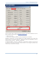
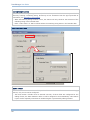
HOW TO CONFIGURE THE SCANNER?
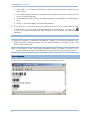
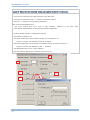
1) Run ScanManager.exe on your computer.
2) Click the drop-down menu of [Select Scanner] on the toolbar, and select the scanner
you want to configure. If you are using ScanManager for the first time, click to expand
the Scanner Information by category so that the default settings of the scanner can be
viewed.
3) To create a new configuration file, click
To open an existing configuration file, click
or
on the toolbar.
on the toolbar.
To clone configuration from another scanner, click Configure | Read Scanner
Settings. This scanner has to be connected to the host computer via RS-232 or
Virtual COM (BT SPP or USB VCOM).
Note: If you are using USB Virtual COM for the first time, you must install its driver from
the CD-ROM. Driver version 5.3 or later is required. Please remove older versions!
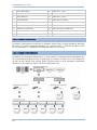
4) Proceed to configure the scanner. The data process is illustrated below.
1. The scanner will work with the settings specified on the Scanner tab.
2. It will read barcodes only if their symbologies are enabled, and output data in the
desired letter case as selected on the Symbology tab.
3. It will perform character substitution as defined on the Format Editing tab.
4. It will add 2-digit length code to desired symbologies as selected on the Length
Code tab.
3
ScanManager User Guide
5. It will add 1- or 2-character identifier to desired symbologies as selected on the
Code ID tab.
6. It will apply editing formats on desired symbologies that meet the criteria set out
on the Format Editing tab.
7. It will add prefix/suffix code to enabled symbologies as selected on the Symbology
tab.
8. Finally, it will output data via the desired interface.
5) If the scanner is connected to the host computer via RS-232 or Virtual COM (BT SPP
or USB VCOM), you can directly download the settings. Otherwise, you can click
to print out setup barcodes and load settings to the scanner by reading setup
barcodes.
Note: The program PrintBarcode.exe must be in the same folder of ScanManager.
6) When the scanner is configured successfully, connect it to the host computer via a
proper interface: Keyboard wedge, RS-232, Wand Emulation, BT HID, BT SPP, USB
HID, or USB Virtual COM.
Note: If the scanner is set to the Wand Emulation mode, you need to connect it to a
portable data terminal or a decoder that is expecting input from a wand scanner.
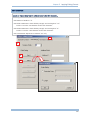
SETUP BARCODES
If you want to restore default settings, scan these barcodes one by one.
4
Introduction
Setup Barcodes
Indication
Enter Setup
Scan this barcode to enter the configuration mode –
Restore
Settings
the LED indicator will become flashing red
Default Scan this barcode to restore the default settings. When the scanner has
successfully read the barcode –
Update
it will respond with six beeps (high-low tone repeats three times), and
it will respond with two beeps (high-low tone)
Scan this barcode to confirm the updating –
it will respond with six beeps (high-low tone repeats three times), and
the LED indicator will go off.
When the scanner has successfully updated the settings, it will restart itself
and respond with one long beep.
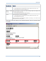
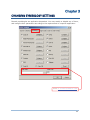
If you want to load new settings, scan associated barcodes. Take the screenshot below
for example.
5
ScanManager User Guide
You can always restore the default settings.
The setup barcodes are categorized into groups of related settings, such as Scanner
Settings, Prefix/Suffix Settings, Interface Settings, Code ID Settings, etc.
After having made any changes to settings, you need to scan the "Update" barcodes
to confirm such action. However, if a decimal or hexadecimal value is involved in the
setting, you need to scan the "Validate" barcode before the "Update" barcode.
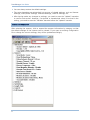
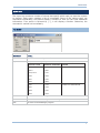
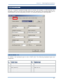
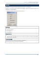
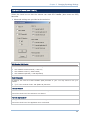
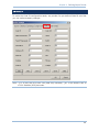
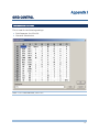
SCANNER INFORMATION
After selecting the scanner, click to expand the scanner information by category so that
the default settings of the scanner can be viewed. If you open an existing configuration
file or change the current settings, they will be updated accordingly.
6
Introduction
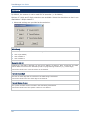
MENU BAR
The menu bar contains a number of menus that specify which task you want the system
to perform. Each menu contains a list of commands. Some of the options carry out
commands immediately, and others display a window so that you can enter additional
information. If an option is followed by [...], it will display a window. Otherwise, the
command is carried out immediately.
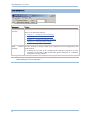
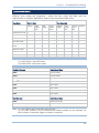
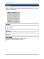
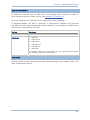
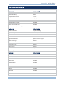
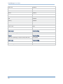
FILE MENU
Command
To Do…
New
To create a new configuration file.
Open
To open an existing configuration file. File path needs to be specified.
Scanner series
Filename extension Remark
1000
*.100
1090+
*.090
1100/1105
*.110
1166
*.166
1200
*.120
1266
*.266
1160
*.116
1260
*.126
14XX
*.140
1045
*.045
Product line discontinued
Save
To save the current settings.
Save As
To save the current settings to a new configuration file.
Exit
To close the ScanManager program.
7
ScanManager User Guide
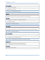
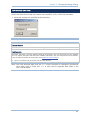
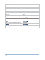
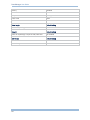
CONFIGURE MENU
Command
To Do…
Configure
Scanner
Configure the current settings for the target scanner.
Refer to the following sections –
Chapter 1 – Changing Scanner Settings
Chapter 2 – Selecting Output Interface
Chapter 3 – Changing Symbology Settings
Chapter 4 – Defining Output Format
Chapter 5 – Applying Editing Formats
Read
Scanner To clone settings or simply modify them, upload the current settings from the
Settings
target scanner.
A dialog box will pop up for configuring the COM port properties on your
computer. For BT SPP or USB Virtual COM, specify COM port for connection
and ignore the rest settings.
Note: To clone settings, first read settings from a specific scanner, and then download
these settings to other scanners.
8
Introduction
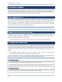
DOWNLOAD MENU
Command
To Do…
Download
Settings
Download the settings to the target scanner if it is connected to the host
computer via RS-232 or Virtual COM (BT SPP or USB VCOM).
A dialog box will pop up for configuring the COM port properties on your
computer. For BT SPP or USB Virtual COM, specify COM port for connection
and ignore the rest settings.
Print
Scanner Run PrintBarcode.exe to print out the Setup Barcodes, which will be
automatically saved in the Barcode.prn file.
Settings
If the scanner is not connected to the host computer via RS-232 or Virtual COM
(BT SPP or USB VCOM), scanner configuration can be changed by scanning the
setup barcodes.
The setup barcodes are categorized into groups of related settings.
9
ScanManager User Guide
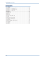
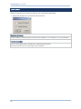
HELP MENU
Command
To Do...
About
ScanManager
Provide version information of the software.
10
Introduction
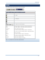
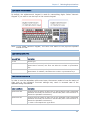
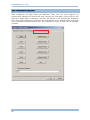
TOOLBAR
The toolbar allows quick access to most commands.
From left to right, the icons stand for the following commands:
New
Open
Save
Configure
Print
Download Settings
Select one of the scanners
1000
CCD scan engine, contact type, width of field 65 mm
1090+
CCD scan engine, contact type, width of field 90 mm
1100/1105
Linear imaging scan engine
Note
1160
BT scanner with linear imaging engine, fixed battery
1166
BT scanner with linear imaging engine, replaceable battery
1200
1260
Laser scan engine
Note
1266
14xx
BT scanner with laser engine, fixed battery
BT scanner with laser engine, replaceable battery
Note
1045 Note
Fixed linear imaging module
Fixed linear imaging scan engine
Note: The product lines have been discontinued.
11
ScanManager User Guide
12
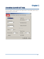
Chapter 1
CHANGING SCANNER SETTINGS
You may configure scanner settings of the target scanner. The available options may be
slightly different for each model.
13
ScanManager User Guide
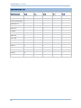
Basically, the default settings for each model are the same except for the following:
Scanner Model
Scan Mode
Auto Sense
RF Auto-Shutdown
Memory Scanner
Transmit Buffer
1000
Auto Off
N/A
N/A
N/A
N/A
1090+
Auto Off
N/A
N/A
N/A
N/A
1100 /1105
Laser
Disabled
N/A
N/A
N/A
Laser
Disabled
10 min.
Disabled
N/A
1166
Laser
Disabled
10 min.
Disabled
Disabled
1200
Laser
N/A
N/A
N/A
N/A
1260 Note
Laser
N/A
10 min.
Disabled
N/A
1266
Laser
N/A
10 min.
Disabled
Disabled
14XX Note
Continuous
Disabled
N/A
N/A
N/A
Note
Continuous
Disabled
N/A
N/A
N/A
1160
1045
Note
Note: The product lines have been discontinued.
IN THIS CHAPTER
1.1
1.2
1.3
1.4
1.5
1.6
1.7
14
Scanning Mode .......................................................... 15
Power Management (1166/1266) ................................. 18
Status Indicator ......................................................... 19
Read Negative Barcode ............................................... 20
Auto Sense (1100 Only).............................................. 20
Memory Mode (1160, 1166, 1260, 1266)....................... 20
Transmit Buffer.......................................................... 20
Chapter 1
Changing Scanner Settings
1.1 SCANNING MODE
Different scan modes are supported – select the scan mode that best suits the
requirements of a specific application. Refer to the comparison table below.
Start to Scan
Scan Mode
Always
Continuous mode
9
Test mode
9
Press
trigger
once
Hold
trigger
9
Laser mode
Press
trigger
twice
Release
trigger
Press
trigger
once
9
9
Auto Off mode
Auto Power
mode
Stop Scanning
9
Alternate mode
Momentary mode
9
9
9
9
9
Off
Repeat mode
Barcode Timeout
being
read
9
9
9
9
9
Note: By default, the scan mode is set to Laser mode for all scanners but
(1) 1000/1090+: Auto Off mode
(2) 14XX/1045: Continuous mode
Handheld Scanner
Default Scan Mode
1000
Auto Off mode
1090+
Auto Off mode
1100 / 1105
Laser mode
1160 Note
Laser mode
1166
Laser mode
1200
1260
Laser mode
Note
Laser mode
1266
Laser mode
Fixed Scanner
Default Scan Mode
14XX Note
Continuous mode
Note
Continuous mode
1045
Note: (1) The product lines have been discontinued.
(2) For fixed scanners, only Continuous and Testing modes can be selected. For
other modes, an external trigger or button is required.
15
ScanManager User Guide
Continuous Mode
The scanner is always scanning.
To decode the same barcode repeatedly, move away the scan beam and target it at the
barcode for each scanning.
Note: Refer to “Delay between Re-read”.
Test Mode
The scanner is always scanning.
Capable of decoding the same barcode repeatedly, for testing purpose.
Laser Mode
The scanner will start scanning once the trigger is held down.
The scanning won't stop until (1) a barcode is decoded, (2) the pre-set timeout expires, or (3)
you release the trigger.
Note: Refer to “Scanning Timeout”.
Auto Off Mode
The scanner will start scanning once the trigger is pressed.
The scanning won't stop until (1) a barcode is decoded, and (2) the pre-set timeout expires.
Note: Refer to “Scanning Timeout”.
Auto Power Off Mode
The scanner will start scanning once the trigger is pressed.
The scanning won't stop until the pre-set timeout expires, and, the pre-set timeout period
re-counts after each successful decoding.
Note: Refer to “Delay between Re-read” and “Scanning Timeout”.
Alternate Mode
The scanner will start scanning once the trigger is pressed.
The scanning won't stop until you press the trigger again.
Repeat Mode
The scanner is always scanning.
16
Chapter 1
Changing Scanner Settings
To decode the same barcode repeatedly, press the trigger again within one second after a
successful reading, the same data will be re-transmitted without actually reading the barcode.
Such re-transmission can be activated as many times as needed, as long as the time interval
between each triggering does not exceed one second.
Note: It will decode once for the same barcode and allow for re-transmission when you
press the trigger again within one second.
Momentary Mode
The scanner will start scanning once the trigger is held down.
The scanning won't stop until you release the trigger.
Note: Refer to “Delay between Re-read”.
1.1.1 SCANNING TIMEOUT
Specify the scanning time interval (1~255 sec.; 0= disable) when the scan mode is set to
any of the following scan mode –
Laser mode
Auto Off mode
Auto Power Off mode
1.1.2 RE-READ DELAY
This is also referred to as the “Blocking Time”, which is used to prevent the scanner from
accidentally reading the same barcode twice when the scan mode is set to any of the
following scan mode —
Continuous mode
Auto Power Off mode
Alternate mode
Momentary mode
1.1.3 READ REDUNDANCY
Select the level of reading security. For example,
If "No Redundancy" is selected, one successful decoding will make the reading valid
and induce the "READER Event".
If "Three Times" is selected, it will take a total of four consecutive successful
decodings of the same barcode to make the reading valid. The higher the reading
security is (that is, the more redundancy the user selects), the slower the reading
speed gets.
It is obvious that the more redundancy you select, the higher the reading security is, and
thus, the slower the reading speed becomes. You will have to compromise between
reading security and decoding speed.
17
ScanManager User Guide
1.2 POWER MANAGEMENT (1166/1266)
The scanner will stay active at power-on for 1 minute, which will be followed by different
power-saving mechanism.
Power-Saving: When the scanner fails to connect within 1 minute, it will enter
power-saving mode automatically.
RF Auto-Shutdown (1~255 min.; 0= Disable): By default, when the scanner is idle for
10 minutes, it will automatically stop RF connectivity. If this feature is not desired, set
it to 0.
Before establishing a WPAN connection successfully…
1.
The scanner will stay active for a preset period of time (1 minute) for the following scenarios.
Its LED is flashing blue (On/Off ratio 1:1).
(a) waiting for a connection request from the host (BT SPP Slave Mode)
(b) trying to connect to the host (BT HID)
(c) trying to connect to 3666
2.
If it fails to connect within 1 minute, the scanner will become inactive to save power, and its
LED will turn off.
Press the trigger to wake up the scanner when it becomes inactive, and the scanner will stay
active again.
Note: For scenarios (a) and (b) in step 1, on your computer you may need to search for
the scanner again.
After establishing a WPAN connection successfully…
1.
Once a WPAN connection is established successfully, the scanner will stay active for data
transmission. Its LED is flashing blue (On/Off ratio 1:6).
2.
With the use of 3666, the scanner will automatically stop RF connectivity when it is idle for the
specified time interval for RF Auto-Shutdown. You will hear three short beeps, tone
descending from high to low, and its LED will turn off.
Press the trigger to wake up the scanner when it becomes inactive, and the scanner will stay
active again.
18
For BT HID or SPP, there is no implementation of RF Auto-Shutdown.
Chapter 1
Changing Scanner Settings
1.3 STATUS INDICATOR
1.3.1 BUZZER
The buzzer of the scanner beeps differently to indicate various operating conditions.
Select the check box if audible signals are not desired.
Conditions
Description
Power On Beep
The scanner will generate a long beep to indicate it is turned on
successfully.
Good Read Beep
The scanner will generate a beep to indicate it successfully reads
a barcode. You may select other frequency than the default 4
KHz.
Error Beep
The scanner will generate a long beep in the lower tone to
indicate errors.
Enter Configuration Beep
The scanner will generate
configuration mode.
6
beeps
upon
entering
the
Update / Exit Configuration The scanner will generate 6 beeps followed by one long beep
Beep
upon exiting the configuration mode.
Setup Beep
In configuration mode, the scanner will normally beeps twice
when a setup barcode is read.
When a particular parameter needs to make use of more than
one setup barcode, the scanner will only generate a short beep to
indicate there are more setup barcodes that need to be read in
order to complete the current parameter setting.
Full Memory Beep
For 1166 and 1266:
When "Memory Scanner" is enabled and the memory becomes
full, the scanner will sound a warning, 3 beeps in the lower tone.
1.3.2 GOOD READ LED
There is a dual-color LED indicator on top of the scanner. Normally, it is off except for the
following conditions:
Conditions
Description
Good Read
LED turns solid red
Configuration Mode
All models except for 1166 / 1266:
LED turns solid green
For 1166 / 1266 only:
LED turns solid blue
19
ScanManager User Guide
1.4 READ NEGATIVE BARCODE
Normally, barcodes are printed with the color of the bars darker than that of the spaces.
But for negative barcodes, they are printed in the opposite sense just like negative films.
The spaces of negative barcodes are printed with a color darker than that of the bars. You
can configure the scanner to be able to read negative barcodes.
1.5 AUTO SENSE (1100 ONLY)
This mode is only available when you want to seat the scanner in the Auto-Sense Stand.
When you enable this mode, it will force the scanner to apply Laser mode as the scan
mode. However, it works slightly different from the original Laser mode. Now the scanner
will be scanning as long as it is seated in the stand. Whenever a barcode is brought
within range, the scanner will be able to decode it.
Note: Auto-sense can only be enabled for CCD scanner and will force it to Laser mode.
1.6 MEMORY MODE (1160, 1166, 1260, 1266)
By default, memory mode is disabled. When the scanner is set to memory mode, it
means a WPAN connection is disabled. You may set a delay between each data record
while transmitting data back to the server.
The cordless scanner keeps 128 KB flash memory for memory mode operation.
1.7 TRANSMIT BUFFER (1166, 1266)
By default, transmit buffer is disabled. You may enable it for use when the scanner is out
of range. Upon reading a barcode successfully within range, the scanner responds with
one short beep (high tone) and its LED indicator becomes solid red and goes off quickly.
However, the host computer may not receive the data immediately if getting out of
range.
The cordless scanner keeps 4 KB transmit buffer. It can ignore the transmission
status and keep on reading barcodes until the buffer is full.
Note: For 1160 or 1260, it will not be able to scan when out of range.
Transmit Buffer Enabled
When transmit buffer is enabled and the scanner is out of range, the scanner will respond with
two short beeps, high-low tone, upon reading a barcode successfully.
When transmit buffer is full, the scanner will respond with one long beep (low tone) and its
LED indicator will become solid red and go off quickly. You are advised to get back to range.
Transmit Buffer Disabled
20
When transmit buffer is disabled and the scanner is out of range, the scanner will respond
with one long beep (low tone). You are advised to get back to range.
Chapter 2
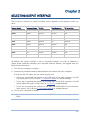
SELECTING OUTPUT INTERFACE
There are four options for output interface, which depend on the scanner model you
have:
Scanner Model
Keyboard Wedge
RS-232
Wand Emulation
BT Serial Port
1000
Default
optional
optional
N/A
1090+
Default
optional
optional
N/A
1100 /1105
Default
optional
optional
N/A
1160
Default
optional
N/A
optional
1166
Default
optional
N/A
optional
1200
Default
optional
optional
N/A
1260
Default
optional
N/A
optional
1266
Default
optional
N/A
optional
14XX
N/A
Default
optional
N/A
1045
optional
Default
optional
N/A
By default, the output interface is set to “Keyboard Wedge”. In order to establish a
proper wired connection between your computer and the scanner, we suggest that you
follow these instructions –
1) Turn off your computer or laptop.
2) Connect the provided interface cable between the scanner and your computer.
If using the RS-232 cable, join the power supply cord.
If you are connecting the scanner to the USB port of the host computer via USB
HID cable (part # 307), refer to 2.1 Keyboard Wedge for related settings.
If you are connecting the scanner to the USB port of the host computer via USB
Virtual COM cable (part # 308), refer to 2.2 RS-232 related settings.
If you are connecting the scanner to the IBM POS 4683/4694 via the converter
cable (part # 346), refer to 2.1 Keyboard Wedge for related settings.
3) Turn on your computer or laptop.
Note: For 1166/1266, it allows you to connect the RS-232 or Keyboard Wedge cable via
3666.
21
ScanManager User Guide
IN THIS CHAPTER
2.1
2.2
2.3
2.4
22
Keyboard Wedge........................................................ 23
RS-232..................................................................... 29
Wand Emulation ........................................................ 31
BT Serial Port ............................................................ 33
Chapter 2
Selecting Output Interface
2.1 KEYBOARD WEDGE
Use the "Y-shaped" keyboard wedge cable to connect the scanner or 3666 between the
keyboard input port of the host computer and the keyboard. The scanned data will be
transmitted to the host keyboard port as if it is manually entered via the keyboard.
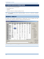
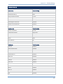
2.1.1 KEYBOARD TYPE
By default, the keyboard type is set to PCAT (US). The following keyboard types are
supported –
No.
Keyboard Type
No.
Keyboard Type
1
PCAT (US)
15
PS55 001-81
2
PCAT (French)
16
PS55 001-2
3
PCAT (German)
17
PS55 001-82
4
PCAT (Italian)
18
PS55 001-3
5
PCAT (Swedish)
19
PS55 001-8A
23
ScanManager User Guide
6
PCAT (Norwegian)
20
PS55 002-1, 003-1
7
PCAT (UK)
21
PS55 002-81, 003-81
8
PCAT (Belgium)
22
PS55 002-2, 003-2
9
PCAT (Spanish)
23
PS55 002-82, 003-82
10
PCAT (Portuguese)
24
PS55 002-3, 003-3
11
PS55 A01-1
25
PS55 002-8A, 003-8A
12
PS55 A01-2 (Japanese)
26
IBM 3477 Type 4 (Japanese)
13
PS55 A01-3
27
PS2-30
14
PS55 001-1
28
IBM 34XX/319X, Memorex Telex 122 Keys
2.1.2 ALTERNATE COMPOSING
By default, Alternate key composing is disabled. Select [Yes] to allow emulating Alternate
key code of a specific keyboard character. For example, [Alt] + [065] will be sent to host
for the character “A” regardless the keyboard type you are using.
2.1.3 ALPHABETS TRANSMISSION
By default, the alphabets transmission is case-sensitive, meaning that the alphabets will
be transmitted according to their original case, the status of Caps Lock on the keyboard,
as well as the Capital Lock setting. Select [Ignore Case] to have alphabets transmitted
according to the status of Caps Lock on the keyboard only.
24
Chapter 2
Selecting Output Interface
2.1.4 DIGITS TRANSMISSION
By default, the alphanumeric keypad is used for transmitting digits. Select “Numeric
Keypad” if you wish to use the keys on the numeric keypad.
Note: If you select “Numeric Keypad”, the Num Lock status of the physical keyboard
should be "ON".
2.1.5 CAPITAL LOCK TYPE
Cap Lock Type
Description
Normal
Normal type
Capital Lock
When enabled, the keys of alphabetic characters will be interpreted as
capital letters. However, this does not affect the number or punctuation
keys.
Shift Lock
When enabled, the keys of alphabetic characters will be interpreted as
capital letters. In addition, this affects the number or punctuation keys.
2.1.6 CAPITAL LOCK STATE
In order to send the alphabets with correct case, the scanner needs to know the status of
Caps Lock on the keyboard. Incorrect settings may result in reversed case of the
alphabets being transmitted.
Capital Lock State
Description
Capital Lock OFF
Assuming that the status of Caps Lock on the keyboard is OFF, transmitted
characters are exactly the same as in the barcode (when "case-sensitive" is
selected for Alphabets Transmission).
Capital Lock ON
Assuming that the status of Caps Lock on the keyboard is ON, transmitted
characters are exactly the same as in the barcode (when "case-sensitive" is
selected for Alphabets Transmission).
Refer to the Capital Lock Type above.
25
ScanManager User Guide
Auto Detection
The scanner will automatically detect the status of Caps Lock on the
keyboard before data is transmitted; transmitted characters are exactly the
same as in the barcode (when "case-sensitive" is selected for Alphabets
Transmission).
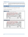
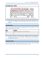
2.1.7 ALPHABETS LAYOUT
By default, the alphabets layout is set to normal mode, also known as the standard
English layout. Select French or German keyboard layout if necessary.
The scanner will make adjustments when sending the "A", "Q", "W", "Z", "Y", and "M"
characters according to this setting.
US Keyboard Style – Normal
QWERTY layout, which is normally used in western countries.
Select “Lower Row” for the “Digits Layout” setting for the upper row is for special characters.
French Keyboard Style – AZERTY
French layout; see below for French Keyboard Style.
26
Select “Upper Row” for the “Digits Layout” setting for the lower row is for special characters.
Chapter 2
Selecting Output Interface
German Keyboard Layout – QWERTZ
German layout; see below for German Keyboard Style.
Select “Lower Row” for the “Digits Layout” setting for the upper row is for special characters.
Note: This setting only works when the keyboard type selected is US keyboard, such as
PCAT (US). The Alphabets Layout and Digits Layout setting must match your
keyboard.
2.1.8 DIGITS LAYOUT
Select a proper layout that matches the alphabets layout. The scanner will make
adjustments according to this setting.
Options
Description
Normal
Depends on the [Shift] key or [Shift Lock] setting
Lower Row
For QWERTY and QWERTZ keyboards
Upper Row
For AZERTY keyboards
Note: This setting is meant to be used with the Alphabets Layout, and perhaps the
Character Substitution setting when support to certain keyboard types (languages)
is unavailable but required.
2.1.9 LAPTOP SUPPORT
By default, laptop support is disabled. Select the check box if you connect the wedge
cable to a laptop without an external keyboard being inter-connected.
27
ScanManager User Guide
2.1.10 INTER-CHARACTER DELAY
By default, the inter-character delay is set to zero. Enter a value, ranging from 0 to 255
in units of millisecond, to match the computer response time of the keyboard interface.
Such delay time is inserted between every character being transmitted. The longer the
delay time is, the slower the transmission speed will be.
28
Chapter 2
Selecting Output Interface
2.2 RS-232
Connect the scanner or 3666 to the serial port of the host computer using the RS-232
cable and join the power adaptor to the RS-232 connector. The associated RS-232
parameters must match those configured on the computer. The scanned data will be
transmitted to the serial port.
2.2.1 TRANSMISSION MODE
Always select “Single Port” because dual port options are not supported by scanner
hardware.
2.2.2 BAUD RATE
By default, it is set 9600 bps. Select other value that matches your computer settings.
2.2.3 DATA BITS
By default, it is set 8 bits of data. Select 7 bits of data if necessary.
29
ScanManager User Guide
2.2.4 PARITY
By default, it is set no parity bit. Select other parity setting, even or odd parity bit.
2.2.5 FLOW CONTROL
By default, there is no flow control in use. Select the flow control (handshake) method.
Options
Description
No
No flow control
Scanner Ready
The scanner will activate the RTS signal upon powering on. After each good
read, the scanner will then wait for the CTS signal to become active. Data
will not be sent until the CTS signal becomes active.
Data Ready
The RTS signal will be activated after each good read. The scanner will then
wait for the CTS signal to become active. Data will not be sent until the CTS
signal becomes active.
Inverted Data Ready
It works the same as the Data Ready flow control, except that the RTS
signal level is inverted.
2.2.6 INTER-CHARACTER DELAY
By default, the inter-character delay is set to zero. Enter a value, ranging from 0 to 255
in units of millisecond, to match the computer response time of the RS-232 interface.
Such delay time is inserted between every character being transmitted. The longer the
delay time is, the slower the transmission speed will be.
30
Chapter 2
Selecting Output Interface
2.3 WAND EMULATION
All batch scanners support wand emulation. Connect the scanner to a portable data
terminal or decoder that is expecting input from a wand scanner.
Note: Wands are handheld optical character readers used to read typewritten fonts,
printed fonts, OCR fonts, and barcodes.
2.3.1 MARGIN TIME
By default, it is set 20 milliseconds as the time span for the change in state for bar and
space modules. Select other value for the margin time.
2.3.2 MODULE TIME
By default, it is set 1 millisecond as the time span for bar and space modules. Select
other value for the module time, in units of micro-second or millisecond.
31
ScanManager User Guide
2.3.3 NORMAL STATE
By default, the signal level is set "Low" for the normal state when not transmitting any
barcode.
2.3.4 BAR STATE
By default, the signal level is set "High" for a bar when transmitting a barcode. Select
"Low" for a bar if "High" for a space is desired.
32
Chapter 2
Selecting Output Interface
2.4 BT SERIAL PORT
Only SPP Slave Mode is supported.
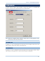
2.4.1 AUTHENTICATION
When any changes are made to authentication and PIN code on the scanner side, you will
have to remove the scanner from the paired device list (called unpairing) and go through
the whole process to re-establish the connection.
Enable Authentication with Preset PIN
Select the check box of “Authentication”, and enter exactly the same string in the “PIN Code” field
as the preset PIN for your computer or PDA to connect to the scanner. If the PIN or passkey is
incorrect, any connection attempt will be turned down by the scanner.
It allows up to 6 characters for a PIN code:
33
ScanManager User Guide
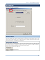
No Authentication
By default, it is set to “No PIN”, which depends on the setting of the target device. (No PIN = No
authentication.)
2.4.2 DEVICE NAME BROADCASTING
The scanner can be configured to hide itself from other devices equipped with Bluetooth®
wireless technology. Simply disable the device name broadcasting setting so that it won’t
be discovered by any other computer or PDA. However, broadcasting must be enabled for
establishing an initial connection with the scanner.
For example, you can disable device name broadcasting after successfully connecting the
scanner to WorkStation1. Such connection will be maintained automatically unless the
scanner is removed from the paired device list (called unpairing) by WorkStation1 or any
changes made to authentication and the PIN code. If you want WorkStation2 to connect
to the scanner, you will have to enable device name broadcasting first.
Note: By default, device name broadcasting is enabled (which is required for initial
connection).
34
Chapter 3
CHANGING SYMBOLOGY SETTINGS
Barcode symbologies are application-dependent. You may enable or disable any of them,
and configure their parameters according to the requirements of a specific application.
Refer 4.2 Prefix/Suffix Code
35
ScanManager User Guide
IN THIS CHAPTER
3.1 Codabar.................................................................... 37
3.2 Code 25 — Industrial 25 ............................................. 38
3.3 Code 25 — Interleaved 25 ........................................... 39
3.4 Code 25 — Matrix 25 .................................................. 40
3.5 Code 39.................................................................... 41
3.6 Code 93.................................................................... 42
3.7 Code 128 .................................................................. 42
3.8 EAN-8 ...................................................................... 43
3.9 EAN-13..................................................................... 44
3.10 GS1-128 (EAN-128) ................................................ 45
3.11 MSI ........................................................................ 46
3.12 French Pharmacode .................................................. 47
3.13 Italian Pharmacode................................................... 47
3.14 Plessey ................................................................... 48
3.15 GS1 DataBar (RSS Family) ........................................ 49
3.16 Telepen .................................................................. 51
3.17 UPC-A..................................................................... 52
3.18 UPC-E..................................................................... 53
36
Chapter 3
Changing Symbology Settings
3.1 CODABAR
By default, the scanner is set to read Codabar barcodes.
Advanced settings are provided as shown below.
Start/Stop Character
Select one of the four different start/stop character pairs.
Transmit Start/Stop Character
Decide whether to include the selected start/stop characters in the data being transmitted.
CLSI Conversion
Decide whether to strip the start/stop characters and insert a space after the first, fifth, and tenth
characters of a 14-character barcode.
This applies to 14-character barcodes only; barcode length does not include the start and stop
characters.
37
ScanManager User Guide
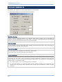
3.2 CODE 25 — INDUSTRIAL 25
By default, the scanner is set to read Industrial 25 barcodes.
Advanced settings are provided as shown below.
Start/Stop Selection
Select a desired start/stop pattern. For example, flight tickets actually use an Industrial 25
barcode but with Interleaved 25 start/stop pattern. In order to read this barcode, the start/stop
pattern selection of Industrial 25 should set to Interleaved 25.
Verify Check Digit
Decide whether to verify check digit when decoding Industrial 25 barcodes. If the check digit is
incorrect, the barcode will not be accepted.
Transmit Check Digit
The check digit will be included in the data being transmitted.
Cancel the check box if the check digit is not desired.
Length Qualification
Because of the weak structure of the 2 of 5 barcodes, it is possible to make a "short scan" error.
To prevent the "short scan" error, configure the "Length Qualification" settings to ensure that the
correct barcode is read by qualifying the allowable code length. The barcode can be qualified by
"Fixed Length" or "Max/Min Length".
38
For "Fixed Length", up to 2 fixed lengths can be specified.
For "Max/Min Length", the maximum length and the minimum length must be specified. The
scanner will only accept those barcodes with lengths that fall between max/min lengths
specified.
Chapter 3
Changing Symbology Settings
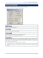
3.3 CODE 25 — INTERLEAVED 25
By default, the scanner is set to read Interleaved 25 barcodes.
Advanced settings are provided as shown below.
Start/Stop Selection
Select a desired start/stop pattern.
Verify Check Digit
Decide whether to verify check digit when decoding Industrial 25 barcodes. If the check digit is
incorrect, the barcode will not be accepted.
Transmit Check Digit
The check digit will be included in the data being transmitted.
Cancel the check box if the check digit is not desired.
Length Qualification
Because of the weak structure of the 2 of 5 barcodes, it is possible to make a "short scan" error.
To prevent the "short scan" error, configure the "Length Qualification" settings to ensure that the
correct barcode is read by qualifying the allowable code length. The barcode can be qualified by
"Fixed Length" or "Max/Min Length".
For "Fixed Length", up to 2 fixed lengths can be specified.
For "Max/Min Length", the maximum length and the minimum length must be specified. The
scanner will only accept those barcodes with lengths that fall between max/min lengths
specified.
39
ScanManager User Guide
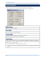
3.4 CODE 25 — MATRIX 25
Select the check box so that the scanner can read Matrix 25 barcodes.
Advanced settings are provided as shown below. Refer to Industrial 25.
Start/Stop Selection
Select a desired start/stop pattern.
Verify Check Digit
Decide whether to verify check digit when decoding Matrix 25 barcodes. If the check digit is
incorrect, the barcode will not be accepted.
Transmit Check Digit
The check digit will be included in the data being transmitted.
Cancel the check box if the check digit is not desired.
Length Qualification
Because of the weak structure of the 2 of 5 barcodes, it is possible to make a "short scan" error.
To prevent the "short scan" error, configure the "Length Qualification" settings to ensure that the
correct barcode is read by qualifying the allowable code length. The barcode can be qualified by
"Fixed Length" or "Max/Min Length".
40
For "Fixed Length", up to 2 fixed lengths can be specified.
For "Max/Min Length", the maximum length and the minimum length must be specified. The
scanner will only accept those barcodes with lengths that fall between max/min lengths
specified.
Chapter 3
Changing Symbology Settings
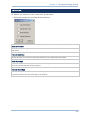
3.5 CODE 39
By default, the scanner is set to read Code 39 barcodes.
Advanced settings are provided as shown below.
Code 39 Full ASCII
Decide whether to support Code 39 Full ASCII that includes all the alphanumeric and special
characters.
Transmit Start/Stop
Decide whether to include the start/stop characters in the data being transmitted.
Verify Check Digit
Decide whether to verify check digit when decoding Code 39 barcodes. If the check digit is
incorrect, the barcode will not be accepted.
Transmit Check Digit
The check digit will be included in the data being transmitted.
Cancel the check box if the check digit is not desired.
41
ScanManager User Guide
3.6 CODE 93
By default, the scanner is set to read Code 93 barcodes.
No advanced settings are available.
3.7 CODE 128
By default, the scanner is set to read Code 128 barcodes.
No advanced settings are available.
42
Chapter 3
Changing Symbology Settings
3.8 EAN-8
By default, the scanner is set to read EAN-8 barcodes. (= No Addon)
Options of 2-digit and 5-digit extensions are available. Select the check box so that it can
read Addon 2 and/or Addon 5.
Advanced settings are provided as shown below.
EAN-8 Family
Select the check box to enable at least one type of the EAN-8 barcodes.
EAN-8 (No Addon)
EAN-8 Addon 2
EAN-8 Addon 5
Convert to EAN-13
Decide whether to expand the read EAN-8 barcode, as well as its addons, into EAN-13.
After conversion, the data follows EAN-13 format and is affected by EAN-13 programming
selections (e.g. Check Digit).
Transmit Check Digit
The check digit will be included in the data being transmitted.
Cancel the check box if the check digit is not desired.
43
ScanManager User Guide
3.9 EAN-13
By default, the scanner is set to read EAN-13 barcodes. (= No Addon)
Options of 2-digit and 5-digit extensions are available. Select the check box so that it can
read Addon 2 and/or Addon 5.
Advanced settings are provided as shown below.
EAN-13 Family
Select the check box to enable at least one type of the EAN-13 barcodes.
EAN-13 (No Addon)
EAN-13 Addon 2
EAN-13 Addon 5
ISBN Conversion
Decide whether to convert the read EAN-13 barcode, which starts with 978 and 979, to ISBN.
ISSN Conversion
Decide whether to convert the read EAN-13 barcode, which starts with 977, to ISSN.
Transmit Check Digit
The check digit will be included in the data being transmitted.
Cancel the check box if the check digit is not desired.
44
Chapter 3
Changing Symbology Settings
3.10 GS1-128 (EAN-128)
Select the check box so that the scanner can read GS1-128 (= EAN-128) barcodes.
Advanced settings are provided as shown below.
Warning:
Code 128 must be enabled first!
Transmit Code ID
Decide whether to include the default Code ID ("]C1") in the data being transmitted.
Field Separator
The FNC1 character is used to separate fields in the barcode. It is not represented in the readable
text. To replace the FNC1 character with readable characters, click the field and choose characters
from the pop-up window of Grid Control (see Appendix I Grid Control).
Up to 2 characters can be chose from the Grid Control.
Note: GS1-128 barcodes start with the FNC1 control character to distinguish themselves
from other uses of Code 128. FNC1 is also used to separate data fields in the
GS1-128 barcodes.
45
ScanManager User Guide
3.11 MSI
Select the check box so that the scanner can read MSI barcodes.
Advanced settings are provided as shown below.
Check Digit Verification
Select the calculation used to verify MSI barcodes. If the check digit is incorrect, the barcode will
not be accepted.
Check Digit Transmission
Select the way the check digits will be included in the data being transmitted.
Length Qualification
Because of the weak structure of MSI barcodes, it is possible to make a "short scan" error. To
prevent the "short scan" error, configure the "Length Qualification" settings to ensure that the
correct barcode is read by qualifying the allowable code length. The barcode can be qualified by
"Fixed Length" or "Max/Min Length".
46
For "Fixed Length", up to 2 fixed lengths can be specified.
For "Max/Min Length", the maximum length and the minimum length must be specified. The
scanner will only accept MSI barcodes with lengths that fall between max/min lengths
specified.
Chapter 3
Changing Symbology Settings
3.12 FRENCH PHARMACODE
Select the check box so that the scanner can read French Pharmacode barcodes.
Advanced settings are provided as shown below.
Check digit verification will be performed when decoding French Pharmacode because
a check digit is always included. However, it is optional to transmit the check digit.
Transmit Check Digit
The check digit will be included in the data being transmitted.
Cancel the check box if the check digit is not desired.
Note: These barcodes share the Transmit Start/Stop setting with Code 39.
3.13 ITALIAN PHARMACODE
Select the check box so that the scanner can read Italian Pharmacode barcodes.
Advanced settings are provided as shown below.
Check digit verification will be performed when decoding Italian Pharmacode because
a check digit is always included. However, it is optional to transmit the check digit.
Transmit Check Digit
The check digit will be included in the data being transmitted.
Cancel the check box if the check digit is not desired.
Note: These barcodes share the Transmit Start/Stop setting with Code 39.
47
ScanManager User Guide
3.14 PLESSEY
Select the check box so that the scanner can read Plessey barcodes.
Advanced settings are provided as shown below.
Convert to UK Plessey
Decide whether to change each occurrence of the character "A" to character "X" in the barcodes.
Transmit Check Digit
The two check digits will be included in the data being transmitted.
Cancel the check box if the check digits are not desired.
48
Chapter 3
Changing Symbology Settings
3.15 GS1 DATABAR (RSS FAMILY)
Select the check box so that the scanner can read GS1 DataBar (also known as RSS)
barcodes.
Advanced settings are provided as shown below.
GS1 DataBar (RSS Family)
Select the check box to enable at least one type of the GS1 DataBar barcodes.
GS1 DataBar Omnidirectional (= RSS-14)
GS1 DataBar Limited (= RSS Limited)
GS1 DataBar Expanded (= RSS Expanded)
Code ID Selection
By default, the Code ID of GS1 DataBar (RSS) barcodes is “]e0”. You may select to use “]C1”
instead.
“]C1” is the Code ID of GS1-128 (EAN-128) barcodes.
Transmit Code ID
The selected Code ID will be included in the data being transmitted.
Cancel the check box if the Code ID is not desired.
Transmit Application ID
The Application ID will be included in the data being transmitted.
Cancel the check box if the Application ID is not desired.
49
ScanManager User Guide
Transmit Check Digit
The check digit will be included in the data being transmitted.
Cancel the check box if the check digit is not desired.
50
Chapter 3
Changing Symbology Settings
3.16 TELEPEN
Select the check box so that the scanner can read Telepen barcodes.
Advanced settings are provided as shown below.
Telepen Full ASCII or Numeric
Select whether AIM Telepen (Full ASCII) or Original Telepen (Numeric) is supported.
Apply Editing Format
Select the check box to apply editing format to Telepen, if there is any. Refer to 5.2.1 Applicable
Conditions.
Note: Telepen is not supported on the 14XX module.
51
ScanManager User Guide
3.17 UPC-A
By default, the scanner is set to read UPC-A barcodes. (= No Addon)
Options of 2-digit and 5-digit extensions are available. Select the check box so that it can
read Addon 2 and/or Addon 5.
Advanced settings are provided as shown below.
UPC-A Family
Select the check box to enable at least one type of the UPC-A barcodes.
UPC-A (No Addon)
UPC-A Addon 2
UPC-A Addon 5
Convert to EAN-13
Expand the read UPC-A barcode, as well as its addons, to EAN-13. After conversion, the data
follows EAN-13 format and is affected by EAN-13 programming selections (e.g. Check Digit).
Cancel the check box if such conversion is not desired.
Transmit Check Digit
The UPC-A check digit will be included in the data being transmitted.
Cancel the check box if the check digit is not desired.
Transmit System Number
The system number will be included in the data being transmitted.
Cancel the check box if the system number is not desired.
52
Chapter 3
Changing Symbology Settings
3.18 UPC-E
By default, the scanner is set to read UPC-E barcodes. (= No Addon)
Options of 2-digit and 5-digit extensions are available. Select the check box so that it can
read Addon 2 and/or Addon 5.
Advanced settings are provided as shown below.
UPC-E Family
Select the check box to enable at least one type of the UPC-E barcodes.
UPC-E (No Addon)
UPC-E Addon 2
UPC-E Addon 5
System Number
By default, the scanner is set to read the ordinary UPC-E barcodes (= UPC-E0 only). You may
change it to read both UPC-E0 and UPC-E1 barcodes.
Convert to UPC-A
Decide whether to expand the read UPC-E barcode, as well as its addons, to UPC-A.
After conversion, the data follows UPC-A format and is affected by UPC-A programming
selections (e.g. System Number, Check Digit).
Transmit System Number
Decide whether to include the system number in the data being transmitted.
Transmit Check Digit
The check digit will be included in the data being transmitted.
Cancel the check box if the check digit is not desired.
53
ScanManager User Guide
54
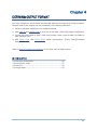
Chapter 4
DEFINING OUTPUT FORMAT
You may configure in which format the collected data will be output to the host computer.
Barcode read by the scanner will be processed in the following sequence –
1) Perform character substitution on the data scanned.
2) Add Code ID and Length Code to the front of the data: [Code ID][Length Code][Data]
3) Process the whole data in step 2 with user formats. Data is now divided into fields by
user specified rules.
4) Add Prefix Code and Suffix Code before transmission: [Prefix Code][Processed
Data][Suffix Code]
Refer to How to Configure the Scanner for the flow chart of data process.
IN THIS CHAPTER
4.1
4.2
4.3
4.4
Character Substitution ................................................ 56
Prefix/Suffix Code ...................................................... 57
Code ID .................................................................... 59
Length Code.............................................................. 62
55
ScanManager User Guide
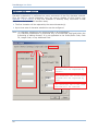
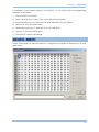
4.1 CHARACTER SUBSTITUTION
Character substitution is performed on every occurrence of the first character entered.
Click the field to choose characters from the pop-up window of Grid Control (see
Appendix I Grid Control). If only one character is entered, every occurrence of that
character in the barcode will be taken away.
The first character will be replaced by the second character(s).
Up to three sets of character substitution can be configured.
Note: (1) Character substitution will be performed on all symbologies.
(2) Character substitution is performed only on the barcode itself and before the
processing of editing formats. It is not applicable to the Prefix/Suffix Code, Code
ID, Length Code, or any Additional Field.
The character “0” in the read
barcode will be replaced by
“Space”.
The character “9” in the read
barcode will be replaced by
“$9”.
The character “W” in the read
barcode will be removed.
56
Chapter 4
Defining Output Format
4.2 PREFIX/SUFFIX CODE
Click the Prefix Code or Suffix Code field so that you can choose characters from the
pop-up window of Grid Control (see Appendix I Grid Control).
Prefix Code: None
Suffix Code: By default, [ENTER] or [CR] (Carriage Return) is entered.
Originally, “Normal Key” is in use by default, Up to eight characters can be chose from
the Grid Control. For example, “Barcode_”, and you will have the string appear in front of
the barcode read, like this — “Barcode_1234567890”.
If "Keyboard Wedge", “BT HID” or “USB HID” is configured for interface, Key Type and
Key Status will then become applicable. Decide whether or not to apply Key Status when
“Normal Key” is selected for Key Type.
57
ScanManager User Guide
Key Type
Key Status
Scan Code
N/A
Normal Key
Add Shift
Add Left Ctrl
Add Left Alt
Add Right Ctrl
Add Right Alt
Add Break
For example, select one of the above keys, say, [Add Shift], and choose
the character [A] from the Grid Control.
58
Chapter 4
Defining Output Format
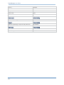
4.3 CODE ID
To make the Code ID configuration easier, we provide five pre-defined Code ID sets that
you can make necessary changes.
Note: “]C1” is the Code ID of GS1-128 (EAN-128) barcodes; “]e0” is the default Code ID
of GS1 DataBar (RSS) barcodes.
59
ScanManager User Guide
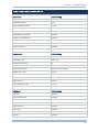
4.3.1 CODE ID SET 1~5
Code ID options
Set 1
Set 2
Set 3
Set 4
Set 5
Code 39
A
C
Y
M
A
Italian Pharmacode
A
C
Y
M
A
French Pharmacode
A
C
Y
M
A
Industrial 25
C
H
H
H
S
Interleaved 25
D
I
Z
I
S
Matrix 25
E
G
G
G
S
Codabar
F
N
X
N
F
Code 93
I
L
L
L
G
ISBT 128
H
K
K
K
C
Code 128
H
K
K
K
C
UPC-E
S
E
C
E
E
EAN-8
P
B
B
FF
E
EAN-13
M
A
A
F
E
UPC-A
J
A
A
A
E
MSI
V
V
D
P
M
Plessey
W
W
E
Q
P
Telepen
Z
---
---
---
---
60
Chapter 4
Defining Output Format
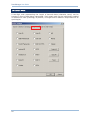
4.3.2 CHANGE CODE ID
To modify the Code ID, click the field next to a symbology. Then, choose your Code ID
from the pop-up window of Grid Control (see Appendix I Grid Control).
Up to two characters for Code ID can be configured for each symbology.
If "Keyboard Wedge", “BT HID” or “USB HID” is configured for interface, Key Type and
Key Status will then become applicable. Decide whether or not to apply Key Status when
“Normal Key” is selected for Key Type.
Key Type
Key Status
Scan Code
N/A
Normal Key
Add Shift
Add Left Ctrl
Add Left Alt
Add Right Ctrl
Add Right Alt
Add Break
For example, select one of the above keys, say, [Add Shift], and choose
the character [A] from the Grid Control.
4.3.3 CLEAR
Click this button to clear the current settings. Default settings will be loaded. That is, the
Code ID settings are empty.
61
ScanManager User Guide
4.4 LENGTH CODE
A two-digit code representing the length of barcode data (character count) can be
inserted in front of data being transmitted. Such length code can be individually enabled
or disabled for each symbology. By default, no length code is added to output data for all
symbologies.
62
Chapter 5
APPLYING EDITING FORMATS
The scanner allows advanced data editing by applying user-configured editing formats.
Data is divided into fields by user-specified rules. These fields together with the
user-configurable additional fields consist of the data actually sent to the host computer.
Up to three different formats can be specified.
IN THIS CHAPTER
5.1 Format Selection ....................................................... 64
5.2 Configure Editing Format ............................................ 65
63
ScanManager User Guide
5.1 FORMAT SELECTION
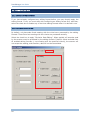
5.1.1 ENABLE EDITING FORMATS
If you have already configured any editing format before, you may directly apply the
editing format. If not, you must start with configuring an editing format first, and then,
select the check box to enable any of the three editing formats when it is desired in use.
5.1.2 EXCLUSIVE DATA EDITING
By default, only barcodes found meeting with the criteria are processed by the editing
formats. Those found not meeting with the criteria are processed normally.
Select the check box to apply “Exclusive Data Editing”. When applied, all barcodes read
by the scanner must be processed by the editing formats. If data is found excluded from
all enabled editing formats (= not meeting with the specified criteria), the scanner will
not accept the reading, and therefore, data will not be transmitted.
64
Chapter 5
Applying Editing Formats
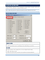
5.2 CONFIGURE EDITING FORMAT
Three applicable conditions can be configured to check whether the data read by the
scanner can be processed by a particular editing format.
Note: Data editing cannot be performed unless the three conditions are all met.
5.2.1 APPLICABLE CONDITIONS
Applicable Code Type
By default, barcodes of all the supported symbologies are eligible for data editing.
Cancel the check box next to a symbology for which data editing is not desired.
Data Length
The length must include prefix, suffix (0x0d by default), length code, etc. By default, barcodes
with length (character count) ranging from 0 to 127 are eligible for data editing.
Enter a value from 0 to 255.
When zero is given to both, the scanner will not perform the length qualification.
65
ScanManager User Guide
Matching String & Location
By default, no matching string is entered, and therefore, it is disabled. You may enable this
feature by entering a matching string. Choose up to four characters from the pop-up window of
Grid Control (see Appendix I Grid Control).
When the Matching String Location is zero, the scanner will only check for the existence of the
matching string in the barcode data.
Enter a value from 1 to 255 to indicate where the matching string starts in the barcode data.
5.2.2 FIELD SETTINGS
Number of Fields
Data can be divided into at most 6 fields; each of them is numbered from F1 to F6 accordingly.
However, only F1~F5 can be configured.
66
The total number of fields must be entered correctly. If three fields are configured for the
editing format, the data characters after F3 will be assigned to F4 automatically. This feature
is quite useful especially when data of variable lengths is processed by editing formats.
Chapter 5
Applying Editing Formats
Field Setting
Data eligible for editing formats is divided into fields by user-specified rules – either using the field
terminating string or specified field length.
Enter the field terminating string. Choose up to two characters from the pop-up window of Grid
Control (see Appendix I Grid Control). The scanner will search for the occurrence of this particular
string in the data. Alternatively, you may simply enter the field length. The scanner will assign the
next specified number of characters into the field.
By default, this terminating string, if exists, will be included in the field. If you wish to discard
it, cancel the check box.
Additional Fields
Up to five additional fields can be created for each editing format; each of them is numbered from
AF1 to AF5 accordingly. To configure the Additional Fields setting, click the associated field and
choose up to four characters from the pop-up window of Grid Control (see Appendix I Grid
Control).
Note: The number of configurable fields is always one less than the total number of
fields specified. The extra data characters beyond the last field configured will be
automatically assigned to the next field.
67
ScanManager User Guide
5.2.3 TRANSMISSION SEQUENCE
After configuring the data fields and additional fields, user can now program the
transmission sequence of these fields that comprise the final data. Simply click on the
buttons of these fields in sequence, and they will appear in the Transmission Sequence
field. This field transmission sequence can be assigned in any desired order and fields
can be assigned multiple times as well. The maximum number of fields can be assigned
is twelve.
68
Chapter 5
Applying Editing Formats
5.2.4 EXAMPLES
Example 1 — Extract data from the 10th character to the 19th character...
The editing format should be configured as follows:
1. Set Number of Fields to "3".
2. Set Field1 Parameters: divide field by Length, and set length to "10".
Field1 = from the 1st character to the 10th character
3. Set Field2 Parameters: divide field by Length, and set length to "9".
Field2 = from the 11th character to the 19th character
4. Set Transmission Sequence to transmit "F2" only.
4
1
2
3
69
ScanManager User Guide
Example 2 — Extract the date code, item number, and quantity information from barcodes.
Data is encoded in the barcode like this:
— From the 1st character to the 6th character is the date code.
— From the 7th character to the "-" character is the item number.
— After the "-" character is the quantity information.
Data will be transmitted like this:
—
The item number goes first, then a TAB character, followed
then another TAB character, and finally the quantity information.
by
the
The editing format should be configured as follows:
1. Set Number of Fields to "3".
2. Set Field1 Parameters: divide field by Length, and set length to "6".
Field1 = from the 1st character to the 6th character
3. Set Field2 Parameters: divide field by Terminating String, and set the string to "-".
Field2 = from the 7th character to the "-" character
4. Set Additional Field 1 to one "TAB" character.
5. Set Transmission Sequence to transmit "F2 A1 F1 A1 F3".
5
1
2
3
70
4
date
code,
Appendix I
GRID CONTROL
ORIGINAL GRID CONTROL
This is used for the following settings:
Field Separator for GS1-128
Character Substitution
Note: For a TAB character, click “HT”.
71
ScanManager User Guide
SPECIAL GRID CONTROL FOR KEYBOARD INTERFACE
This is used for the following settings:
Prefix/Suffix Code
Code ID
Additional Fields for configuring editing format
Note: This is available only when "Keyboard Wedge", “BT HID” or “USB HID” is selected
for interface.
GRID CONTROL — NORMAL KEY
By default, each character programmed is a "Normal Key". Such a character can have
associate status settings by adding the Shift/Control/Alternate keys.
Note: For a TAB character, click “HT”.
72
Appendix I Grid Control
For example, if you want to program "Ctrl-Shift-B", "C" for Prefix Code, the programming
sequence is as follows:
1) Click the Prefix Code field.
2) Select "Normal Key" for Key Type in the Grid Control window.
3) Select the check box of "Add Left Ctrl" and "Add Shift" for Key Status.
4) Choose "B" from the ASCII table.
5) Cancel the check box of "Add Left Ctrl" and "Add Shift".
6) Choose "C" from the ASCII table.
7) Click [OK] to confirm the setting.
GRID CONTROL — SCAN CODE
Select "Scan Code" so that the scanner is configured to program a character by its scan
code value.
73
ScanManager User Guide
74
Appendix II
DEFAULT SETTINGS
1000/1090+ DEFAULTS
Scanner tab
Default Setting
Scan Mode:
Auto Off
Read Redundancy:
None
Delay between Reread:
0.4 sec
Timeout:
10 (sec)
Disable Buzzer:
Enabled, 4 KHz
Read Negative Barcode:
Disabled
Disable Good Read LED:
Enabled
Interface tab
Default Setting
Scanner Interface:
Keyboard Wedge
Keyboard Type:
PCAT (US)
Alternate Composing:
No
Alphabets Transmission:
Case-sensitive
Digits Transmission:
Alpha-numeric Keypad
Capital Lock Type:
Normal
Capital Lock State:
OFF
Alphabets Layout:
Normal
Digits Layout:
Normal
Inter-Character Delay:
0 (ms)
Laptop Support:
Disabled
Symbology
Default Setting
Code 39
Enabled
Italian Pharmacode
Disabled
French Pharmacode
Disabled
Industrial 25
Enabled
Interleaved 25
Enabled
Matrix 25
Disabled
Codabar
Enabled
75
ScanManager User Guide
Code 93
Enabled
Code 128
Enabled
EAN-128
Disabled
UPC-E
Enabled
EAN-8
Enabled
EAN-13
Enabled
UPC-A
Enabled
MSI
Disabled
Plessey
Disabled
RSS
Disabled
Telepen
Disabled
Prefix Code
None
Suffix Code
Enter
Code Length
Default Setting
Same as Symbology
All disabled
Code ID
Default Setting
Same as Symbology except for RSS, EAN-128
All disabled
Edit Format
Default Setting
Character Substitution
None
Data Editing
Disabled
76
Appendix II
Default Settings
1100/1105/1200 DEFAULTS
Scanner tab
Default Setting
Scan Mode:
Laser
Read Redundancy:
None
Delay between Reread:
0.4 sec
Timeout:
10 (sec)
Disable Buzzer:
Enabled, 4 KHz
Read Negative Barcode:
Disabled
Disable Good Read LED:
Enabled
Auto Sense (1100/1105 only):
Disabled
Interface tab
Default Setting
Scanner Interface:
Keyboard Wedge
Keyboard Type:
PCAT (US)
Alternate Composing:
No
Alphabets Transmission:
Case-sensitive
Digits Transmission:
Alpha-numeric Keypad
Capital Lock Type:
Normal
Capital Lock State:
OFF
Alphabets Layout:
Normal
Digits Layout:
Normal
Inter-Character Delay:
0 (ms)
Laptop Support:
Disabled
Symbology
Default Setting
Code 39
Enabled
Italian Pharmacode
Disabled
French Pharmacode
Disabled
Industrial 25
Enabled
Interleaved 25
Enabled
Matrix 25
Disabled
Codabar
Enabled
Code 93
Enabled
Code 128
Enabled
EAN-128
Disabled
UPC-E
Enabled
77
ScanManager User Guide
EAN-8
Enabled
EAN-13
Enabled
UPC-A
Enabled
MSI
Disabled
Plessey
Disabled
RSS
Disabled
Telepen
Disabled
Prefix Code
None
Suffix Code
Enter
Code Length
Default Setting
Same as Symbology
All disabled
Code ID
Default Setting
Same as Symbology except for RSS, EAN-128
All disabled
Edit Format
Default Setting
Character Substitution
None
Data Editing
Disabled
78
Appendix II
Default Settings
1160/1166/1260/1266 DEFAULTS
Scanner tab
Default Setting
Scan Mode:
Laser
Read Redundancy:
None
Delay between Reread:
0.4 sec
Timeout:
10 (sec)
Disable Buzzer:
Enabled, 4 KHz
Read Negative Barcode:
Disabled
Disable Good Read LED:
Enabled
Auto Sense (1166/1266 only):
Disabled
RF Auto-Shutdown
10 (min.)
Memory Scanner:
Disabled
Transmit Buffer (1166/1266 only):
Disabled
Interface tab
Default Setting
Scanner Interface:
Keyboard Wedge
Keyboard Type:
PCAT (US)
Alternate Composing:
No
Alphabets Transmission:
Case-sensitive
Digits Transmission:
Alpha-numeric Keypad
Capital Lock Type:
Normal
Capital Lock State:
OFF
Alphabets Layout:
Normal
Digits Layout:
Normal
Inter-Character Delay:
0 (ms)
Laptop Support:
Disabled
Symbology
Default Setting
Code 39
Enabled
Italian Pharmacode
Disabled
French Pharmacode
Disabled
Industrial 25
Enabled
Interleaved 25
Enabled
Matrix 25
Disabled
Codabar
Enabled
Code 93
Enabled
79
ScanManager User Guide
Code 128
Enabled
EAN-128
Disabled
UPC-E
Enabled
EAN-8
Enabled
EAN-13
Enabled
UPC-A
Enabled
MSI
Disabled
Plessey
Disabled
RSS
Disabled
Telepen
Disabled
Prefix Code
None
Suffix Code
Enter
Code Length
Default Setting
Same as Symbology
All disabled
Code ID
Default Setting
Same as Symbology except for RSS, EAN-128
All disabled
Edit Format
Default Setting
Character Substitution
None
Data Editing
Disabled
80
Appendix II
Default Settings
14XX DEFAULTS
Scanner tab
Default Setting
Scan Mode:
Continuous
Read Redundancy:
None
Delay between Reread:
0.4 sec
Timeout:
10 (sec)
Disable Buzzer:
Enabled, 4 KHz
Read Negative Barcode:
Disabled
Disable Good Read LED:
Enabled
Auto Sense:
Disabled
Interface tab
Default Setting
Scanner Interface:
RS-232
Transmission Mode:
Single Port
Baud Rate:
9600 bps
Data Bit:
8 Bits
Parity:
None
Flow Control:
No
Inter-Character Delay:
0
Symbology
Default Setting
Code 39
Enabled
Italian Pharmacode
Disabled
French Pharmacode
Disabled
Industrial 25
Enabled
Interleaved 25
Enabled
Matrix 25
Disabled
Codabar
Enabled
Code 93
Enabled
Code 128
Enabled
EAN-128
Disabled
UPC-E
Enabled
EAN-8
Enabled
EAN-13
Enabled
UPC-A
Enabled
MSI
Disabled
81
ScanManager User Guide
Plessey
Disabled
RSS
Disabled
Telepen
Not supported on the 14XX module
Prefix Code
None
Suffix Code
CR
Code Length
Default Setting
Same as Symbology
All disabled
Code ID
Default Setting
Same as Symbology except for RSS, EAN-128
All disabled
Edit Format
Default Setting
Character Substitution
None
Data Editing
Disabled
82
Appendix II
Default Settings
1045 DEFAULTS
Scanner tab
Default Setting
Scan Mode:
Laser
Read Redundancy:
None
Delay between Reread:
0.4 sec
Timeout:
10 (sec)
Disable Buzzer:
Enabled, 4 KHz
Read Negative Barcode:
Disabled
Disable Good Read LED:
Enabled
Auto Sense:
Disabled
Interface tab
Default Setting
Scanner Interface:
RS-232
Transmission Mode:
Single Port
Baud Rate:
9600 bps
Data Bit:
8 Bits
Parity:
None
Flow Control:
No
Inter-Character Delay:
0
Symbology
Default Setting
Code 39
Enabled
Italian Pharmacode
Disabled
French Pharmacode
Disabled
Industrial 25
Enabled
Interleaved 25
Enabled
Matrix 25
Disabled
Codabar
Enabled
Code 93
Enabled
Code 128
Enabled
EAN-128
Disabled
UPC-E
Enabled
EAN-8
Enabled
EAN-13
Enabled
UPC-A
Enabled
MSI
Disabled
83
ScanManager User Guide
Plessey
Disabled
RSS
Disabled
Telepen
Disabled
Prefix Code
None
Suffix Code
CR
Code Length
Default Setting
Same as Symbology
All disabled
Code ID
Default Setting
Same as Symbology except for RSS, EAN-128
All disabled
Edit Format
Default Setting
Character Substitution
None
Data Editing
Disabled
84