1
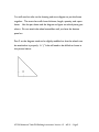
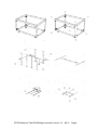
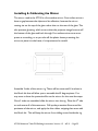
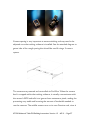
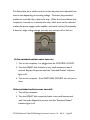
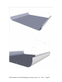
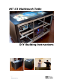
MT-50 Multitouch Table DIY Building Instructions TABLE OF CONTENTS MT-50 Multitouch Table DIY Building Instructions – Version 1.2. For comments or questions you can contact us at: [email protected]. GETTING STARTED About the MT-50 Multitouch Table and DIY Building Instructions Page 03 THE TABLE FRAME Assembling the Aluminum Frame Installing the Bottom Panel Page 04 - 06 Page 07 - 10 THE COMPUTER Assembling the Computer Computer Specifications Page 10 Page 11 - 12 POWER, ILLUMINATION, AND PROJECTION Bottom Panel I/O and Power Faceplates Applying Infrared Light Strips Connecting Low Voltage Electrical Applying Projection Film to Glass and Masking Installing the Glass Surface Installing the Projector Installing & Calibrating the Mirror Installing the Cameras The Smart Strip The Side Panels Page 13 - 14 Page 15 - 16 Page 16 Page 16 - 17 Page 18 Page 21 - 22 Page 23 - 25 Page 25 - 27 Page 28 - 30 Page 30 - 32 SOFTWARE Tracking Software Page 33 PARTS AND SOURCES MT50 Parts Bosch Aluminum pieces Page 34 - 39 Page 39- 40 MT-50 Multitouch Table DIY Building Instructions–Version 1.2 - 4/5/11 - Page 2 ABOUT THE MT-50 & DIY BUILDING INSTRUCTIONS The MT50 is a projection based 50” multitouch table. It is 31” high with casters and meets ADA (American’s with Disabilities Act) standards. The MT50 supports a resolution of 1280x720. Its frame is made of aluminum, the shell is steel, and surface is thick tempered glass. The table is virtually indestructible and is designed for use in busy public spaces. We’ve literally dropped bowling balls on it to test its toughness. Ideum (www.ideum.com), a New Mexico-based company, built and sold MT50 multitouch tables between 2009 and 2010. There are dozens of these tables installed in museums, research labs, and a few are even installed at Fortune 500 companies across North America. The MT50 has been discontinued, as of March 2011 and has been replaced by a LCD based table, the MT55 (you can learn more about the MT55 on the Ideum website: http://www.ideum.com/products/multitouch/). It is worth mentioning that of the techniques used in the MT50 are still used for large-scale installations such as walls, multiple projector tables. While the MT50 documentation is no longer available on the Ideum site. A description, videos, and reviews can be found on the GestureWorks website: http://gestureworks.com/features/supported-hardware/ideum-mt-50-multitouch-table/ The instructions for the MT-50 are being released as part of the Open Exhibits, museum software and hardware initiative. Open Exhibits multitouch and multiuser software is free to students, museums, nonprofits, and US Government agencies. Please visit: openexhibits.org for more details. If you have any suggestions for how we might improve these instructions, please let us know. The Ideum and Open Exhibits Team Corrales, New Mexico MT-50 Multitouch Table DIY Building Instructions–Version 1.2 - 4/5/11 - Page 3 Assembling the Aluminum Frame The main frame for the MT-50 is made of Bosch aluminum. The entire kit for the MT-50 can be purchased from our Bosch Supplier in the United States, Pacific Integrated Handling. If you would like to order the kit, please contact Marianne Scarafiotti (or someone in her office) and let them know you’d like the Ideum MT-50(200-05320) kit. Pacific Integrated Handling Inc Marianne Scarafiotti 480-379-0100 (phone) Ideum MT-50(200-05320) kit The kit will come with all the needed aluminum strut, screws, T-nuts, and gussets that are needed to assemble the aluminum frame. If you have ever played with an Erector set, you will be able to put together the Bosch aluminum frame very easily. To assemble, you will need the following tools: 1 Metric 2.5 Hex Key 1 Metric 4 Hex Key 1 12mm Socket w/ wrench The different thicknesses of aluminum strut will be referred to in millimeters. For the most part, the sizes in this kit are 45x45mm, 30x30mm, 20x20mm, and 20x40mm. This size convention also works for the Gussets (the triangular pieces that are used to connect strut). There will be 45mm gussets, 30mm, and 20mm. MT-50 Multitouch Table DIY Building Instructions–Version 1.2 - 4/5/11 - Page 4 You will need to refer to the drawing and strut diagram to put the frame together. The strut chart will show thickness, length, quantity, and a part letter. Use the part letter and the diagram to figure out which piece goes where. Do not attach the wheel assemblies until you have the bottom panel on. Part F on the diagram needs to be slightly modified so that the wheels can be attached to it properly. A ½” hole will need to be drilled as shown in the picture below: MT-50 Multitouch Table DIY Building Instructions–Version 1.2 - 4/5/11 - Page 5 MT-50 Multitouch Table DIY Building Instructions–Version 1.2 - 4/5/11 - Page 6 Installing the Bottom Panel Once the frame is complete, you will want to install the bottom panel. The bottom panel will have 6 120mm fan cutouts, and have cut-outs for 2 boxes; a power box for the incoming 120v power 2x4 handy box), and a cut-out for the Input/Output/Power Switch box (2 gang metal box). To attach the bottom panel to the frame, you will have to orient the panel correctly on the frame. There is one side of the frame that uses Part C (45x45mm strut with a notch cut out). That is the side that the projector will be on. If you were standing on that side of the frame, the bottom panel cut out for the smaller electrical box should be on the right side, the larger electrical box cut out on the left side, both on the opposite of the side you are standing on. Place 14 M5 screws (not included with Bosch kit) and T-nuts into the outside holes around the perimeter of the panel. Once all of the screws and T-nuts are in, flip the entire Bosch frame upside down, and place the panel on with the orientation described above. Line the T-nuts up so that they all fall into the middle channel on the strut. Tighten up all of the screws around the perimeter so that the bottom panel is snug and lined up with the frame. You can now attach the wheels that came with the kit, and should flip the entire assembly on its side to install the fans. MT-50 Multitouch Table DIY Building Instructions–Version 1.2 - 4/5/11 - Page 7 MT-50 Multitouch Table DIY Building Instructions–Version 1.2 - 4/5/11 - Page 8 To install the fans, you will need the following: 24 M3 12mm screws with locking washers and nuts 6 Silicon Vibration Absorbers 6 120mm plastic fan filter 6 120mm fan To create a good flow of air through the table, 3 fans should be blowing air in, and 3 should be pushing air out. If you were standing on the same side of the frame as Part C (notched cut out on strut) then the fans on your left side should be positioned to blow air up and into the table. The other 3 should be positioned the opposite way, blowing the air down and out. Place the silicon vibration absorber on the bottom of the fan, place the fan on top of the bottom panel along the screw holes, place the plastic fan filter on the bottom of the bottom panel, and secure the entire assembly with the M3 screws (not included with Bosch kit). Do this for all of the fans. To install the electrical boxes and I/O box, you will need to do the following: The electrical box and I/O box are going to be facing down. You will need to drill holes in the side of the boxes to allow them to attach to the strut that is on the side of their cutouts. Place the electrical box face down on the bottom panel just below the cutout. Mark the side of the electrical box where the middle channel in the strut is. Use that mark to drill holes on the long side of the boxes. MT-50 Multitouch Table DIY Building Instructions–Version 1.2 - 4/5/11 - Page 9 Before attaching the boxes to the strut, some minor electrical work needs to happen with the two 2x4 handy boxes. One of the boxes will be facing downward in the cut out. The second 2x4 handy box will be facing upward. Remove one of the ½” knockouts on each box, and attach a 1/2” Romex connector. Cut about 2 feet of SO cord, and run between the two boxes. The amount of cable between the boxes can be very short, just make sure you have plenty of cable coming out of each box to wire up the receptacles later on. Make sure one box is facing up and the other facing down and tighten Romex connectors. Use small 8mm T-nuts and accompanying screw to attach the boxes to the strut. Assembling the Computer Below are the specs for the computers that we include in our tables. Parts for this computer are definitely variable, EXCEPT for the IEEE1394 card. This card (since there are limited PCI and PCIE lanes on the small system board) needs to be Dual Channel/Dual Port, 1394A, and we’d recommend that it was a card that had a Texas Instruments chipset. The chipset could cause problems if you are using a camera such as the PT Grey FireflyMV. The emphasis on this kind of card is due to the cameras. If multiple PT Grey FireflyMV cameras are on a single channel, you will overflow the 1394 MT-50 Multitouch Table DIY Building Instructions–Version 1.2 - 4/5/11 - Page 10 bus, and cause something (usually the tracker) to go crazy, or the system to give you a lovely blue screen error. If you intend on using USB cameras such as the PS3Eye, then additional 1394 cards are not necessary. The form factor of the computer is very small. We would recommend you use the case we have listed (or something very similar) to place the system in. The small form factor is needed to fit a high end system in the table without taking up room that would affect the IR lighting and projected image. Computer Specifications The MT50 standard computers have the following hardware: Intel i7 930 2.8GHz processor NVidia GeForce 470 Graphics Card 4GB DDR3-1600 RAM 2 300GB 10,000 RPM SATA hard disk drives in a RAID 1 configuration(using the system boards soft RAID system) Windows 7 Professional 2 dual channel IEEE1394A cards 920 Watt Power Supply Custom power switch set up Many of these parts can be changed out. You will need the 920-Watt power supply (this also powers the fans and IR lights) and the 1394 cards. Using a lower amount of RAM and a slower processor may result in a slightly sluggish computer. MT-50 Multitouch Table DIY Building Instructions–Version 1.2 - 4/5/11 - Page 11 An i7 is not necessary, but at least a quad core of some sort is recommended. 2GB of RAM will work, but a minimum of 4GB is recommended. Hard drive space is at the builder’s discretion. If you plan on having a lot of media, go for large drives. If you are worried about redundancy, double the drives up and set up a RAID. Most tracking software still runs on Windows XP, so that could also be an option for the OS. The power switch on the computer case has been disconnected and hooked directly into the blue LED power switch on the bottom of the table. On most computer system boards, there should be 2 pins for On/Off power button function, and 2 pins for LED power for the On/Off buttons. Refer to the system board manual to locate those pins. The power switch on the MT-50 is located on the bottom 2-gang panel that also has the USB, Audio, HDMI, and RJ-45 connections on it. MT-50 Multitouch Table DIY Building Instructions–Version 1.2 - 4/5/11 - Page 12 Bottom Panel I/O and Power Faceplates There will be two different sized square cutouts with the electrical boxes you installed earlier. The plates and panel mount cables can be ordered from www.datapro.net. The double gang box will be for the I/O connections and the power button. It has the following cut outs: 2x USBA 1x CAT5 2x HDMI 2x 3.5 mm stereo 1x custom circular hole (7/8" diameter) Attach the panel mount cables and the power switch to the plate. You will now have to get the other ends of the cables through the knockouts on the MT-50 Multitouch Table DIY Building Instructions–Version 1.2 - 4/5/11 - Page 13 2 gang electrical box. Once you have all of the cables through the box, attach the face plate to the electrical box with the provided screws. The single gang box will be for the main power inlet for the entire system. We use a C14 inlet (same type of plug you’ll find on the back of any computer). This face place can also be ordered through www.datapro.net. This plate has one C14 cut out on it. MT-50 Multitouch Table DIY Building Instructions–Version 1.2 - 4/5/11 - Page 14 Applying Infrared Light Strips There are three rows of high-intensity infrared LEDs in the table on the lighting rig. Each row is wired independently of the others, so if one connection or strip fails, the others will still work. With less infrared illumination, the table will be impaired but will still function. The LED strips that we use come from Environmental Lights. With the lighting setup we show in the diagrams about 2 ½ rolls ended up being used, so you will need to purchase 3 rolls. There are many different types of IR LED strips, but we have found that the High Brightness with 5050 LEDS work the best for this application. You can find these strips here: http://www.environmentallights.com/products/13104/irrf850-5050-60-reel. These LEDs come in rolls and are backed with an adhesive. To install the LEDs, you’ll first want to measure the LEDs on the aluminum lighting rig. The strips need to be slightly staggered to ensure enough room for the connections. The lengths of the strips do not have to be exact. If you look at the drawing, you can see how we applied them to the aluminum. When you make a cut on the strips, make sure you do it on the designated cut line or you could damage the circuit. Once you’ve cut a strip, check to make sure that it is aligned correctly before adhering it to the rig. The edges of the strips on the outsides of the struts should align with the edge of the strut, and middle strips should be centered on the strut. When applying the strips after you’ve cut them, make sure that the polarity matches up with the other strips to make MT-50 Multitouch Table DIY Building Instructions–Version 1.2 - 4/5/11 - Page 15 wiring easy. We usually just kept the positive side to the outside edge. Check the polarity on the strips by looking for the little + and -. Now that the strips are attached to the rig, you can solder the strip connections. The LED strips have small round pads that can be soldered to. Cut the wire to the correct lengths and silver the ends of the wire. Place a piece of shrink-wrap on the strip before soldering and put a tiny amount of flux on each connection. Get a small bead of solder on your soldering iron and quickly solder each wire to the connections, then heat the shrink wrap to shrink it, making sure the wires are separated. Once all of the cables are connected to the lighting strips, route the cables so that they end up near the computer power supply. You will then need to place 4 pin Molex connectors on each set of wires so that they can be connected to the power system. MT-50 Multitouch Table DIY Building Instructions–Version 1.2 - 4/5/11 - Page 16 Connecting Low Voltage Electrical At this point, you should have the electrical leads from the fans and from the lights routed so that they reach near the computer. Use a 4 square electrical box as a junction point for all of the connections. Route two of the connectors from the computer power supply that have 4 pin Molex connectors on them into the box. Use the Molex connectors to plug in the fans and lighting wires. The fans should have come with 3 pin-to-4 pin adapters. Applying Projection Film to Glass and Masking On our tables, we use custom pieces of glass with projection film on one side. The glass is 10mm thick with a fine micro-etch on the top surface. The glass is etched in a way that doesn't adversely affect the way that light passes through the glass while providing haptic feedback. The micro-etch also provides a reduction in reflected light and an increase in viewing angle to almost 180 degrees. The diffusion material on the underside of the glass is a custom projection film selected to provide the best performance with short-throw projectors. The material actively scatters the light, giving the screen a low incidence angle (meaning the image is viewable from a wide range of angles) with evenly distributed brightness. Applying the projection film to the glass can be tricky with this setup. MT-50 Multitouch Table DIY Building Instructions–Version 1.2 - 4/5/11 - Page 17 What we have listed is what we use, and have found to work best for this application. Of course there are always other methods, some much cheaper. We used Spyeglass (www.spyeglass.com) SpyeSmoke film on the MT-50, cut to 34.5” x 53.5”. This film worked best with the short throw projector we used, and had little to no hot spotting. You can apply this film yourself by following the instructions included, but we used a professional tinting company to apply ours, and to apply the black mask that borders the edge. Once the film is applied, we masked off the outside area of the glass to be painted black. The mask was 4 15/16” off of each edge. You can use painter’s tape and some plastic to protect the inside area of film from being painted. We came to these mask dimensions for a few reasons; it gives us a 50” diagonal image, and it covers up the projector that is installed on the side of the table. Peau Productions offers a good page that shows other diffusion material options. You can find that here http://peauproductions.com/diffusers.html Installing Glass Surface Before installing the glass into the table, you’ll need to put a rubber seal on the steel mantle to help seal the table against liquids and cushion the glass. We used 3M 2228 Moisture Sealing Electrical Tape. Cut and apply the strips along the 4 pieces of the top mantle. MT-50 Multitouch Table DIY Building Instructions–Version 1.2 - 4/5/11 - Page 18 With the mantle placed in the aluminum frame without the glass, mark precisely where the holes on the inside of the mantle are on the aluminum strut. After you have marked those holes, remove the mantle and place 8mm T-nuts with an M4 hole exactly where you made the marks. To hold the T-Nuts in place, you can wedge some masking tape around the nut. Once the tape is applied and the T-nuts are placed into the aluminum frame, you are ready to place the glass in. This will take 2 or 3 people. Place the two shorter pieces of the mantle into the frame. Place the glass into one end, and rest that end in the aluminum frame. Lift the other side of the glass up and place the other short piece on the glass. Lift the entire piece of glass out, and place the two longer pieces of the mantle on the glass, and lower the entire construction into the aluminum frame. Once it is in, secure the top mantle with M4 screws into the T-nuts that were placed into the frame previously. MT-50 Multitouch Table DIY Building Instructions–Version 1.2 - 4/5/11 - Page 19 MT-50 Multitouch Table DIY Building Instructions–Version 1.2 - 4/5/11 - Page 20 Installing the Projector The table uses an InFocus IN-1503 short-throw projector. With a projection throw ratio of 0.7:1 (projection distance: image width) it's one of the shortest-throw projectors on the market, and, after testing several different models we've found that this projector has the most predictable optical behavior. You can use a different projector, but you’ll want to make sure it’s a shortthrow projector; otherwise, the image being projected may be quite a bit smaller. To hold the projector in place, we use a custom steel plate that is screwed into the table’s aluminum frame. The projector must be carefully screwed onto the plate. MT-50 Multitouch Table DIY Building Instructions–Version 1.2 - 4/5/11 - Page 21 There are 3 holes in the middle of the plate, and 3 holes on the bottom of the projector. Between the plate and the projector, you will want to use ¼” nylon spacers with a non-threaded hole in the middle. Place the spacers over the holes on the projector, and place the plate on top, lining up the holes. Attach with 12mm M4 counter sunk pan head screws. Once you have the plate and projector put together, you will need to attach it to the aluminum struts marked H on the frame diagram. To attach to this strut, the 4 outside holes on the plate will need an M4 screw with a 6mm T-Nut. You will want to move the projector assembly as high up on the strut as possible, but before you do that you will need to attach the 90 degree HDMI connector and the 90 degree power cord. The power cord should slide into the cut out in the strut (Part C). Once the projector is installed, hook it up to the computer, and power it on. You will want to change some basic settings on the projector so that it doesn’t reset keystone, power off, etc. Change the following settings: AC Power On ON Auto Source OFF Power-Up Source HDMI Auto Keystone OFF Replacement bulbs for the projector can be ordered here. MT-50 Multitouch Table DIY Building Instructions–Version 1.2 - 4/5/11 - Page 22 Installing & Calibrating the Mirror The mirror used in the MT-50 is a first surface mirror. First surface mirrors have no gap between the object and its reflection, because the mirror coating sits on the top of the glass rather than on the rear of the glass. This also prevents ghosting, which occurs when the projector image bounces off the bottom of the glass and back through. First surface mirrors are more prone to scratching, so as you take off the plastic sheets protecting the mirror to place it in the frame, it’s important to be careful. Assemble 3 sides of the mirror rig. There will be some small L brackets in the Bosch kit that will allow you to assemble the 45 degree pieces. You may want to leave the protective film on the mirror for the next few steps. Once 3 sides are assembled, slide the mirror into the rig. Place the 4th side on and secure all of the setscrews. Pull up the protective film around the perimeter of the mirror, and apply the thin rubber stripping that came with the Bosch kit. This will keep the mirror from sliding around inside the rig. MT-50 Multitouch Table DIY Building Instructions–Version 1.2 - 4/5/11 - Page 23 Once the mirror is placed in the frame, two rows of infrared LED strips need to be applied to the frame. These LEDs are wired in one circuit. See the wiring diagram to see how the mirror LED strips are placed and wired. The mirror is connected to the frame by the 4 mirror turrets (Part N). Four 20x20mm gussets will be used to attach the mirror to the turrets, and to be able to make adjustments to the angle of the mirror. The four gussets need to be slightly modified. There are 2 tabs on each side of the gusset that usually sit in the middle channel of the strut. Remove these tabs on one side so that the mirror will be able to sit flat on that side of the gusset. Attach the gussets to the inside of the turrets and place the mirror on the gussets. Loosely screw the gussets to the mirror rig. Power on the computer and start up the projector. You should have configured the computer to output to the projector with a resolution of 1280x720. The IN1503 projector has a physical zoom knob that should be zoomed in as far as possible. You will now have to adjust the gussets attached to the turrets and mirror to get the projected image to fit within the masked off area on the glass. Since you will be moving the mirror at different angles, you will have to adjust the keystone setting on the projector. You can access the keystone settings on the projector by using the remote control. MT-50 Multitouch Table DIY Building Instructions–Version 1.2 - 4/5/11 - Page 24 Press the menu button, press select on the Basic Picture option, and scroll down to Keystone. Try starting at a keystone of about 54, and then adjust the mirror from there. Installing the Cameras Three PT Grey Firefly MV (Firewire version) cameras are used in the MT50 to track the finger movements on the table surface. The cameras come in a small plastic case with a mount assembly. Before mounting the cameras, they need to be taken apart to install the band pass filter. Remove the case of the cameras to reveal a small circuit board. MT-50 Multitouch Table DIY Building Instructions–Version 1.2 - 4/5/11 - Page 25 There will be a lens mount attached to the board by two screws. Remove the lens mount to reveal a rubber grommet and a small clear lens. You will also see the small CMOS sensor in the middle of the board. This is essentially the ‘lens’ of the camera, so be sure not to allow anything to come into contact with it. Remove the rubber grommet, and take out the clear lens. Replace the clear lens with the band pass filter. Reassemble the camera. Once the plastic case is back together, you can then put on the camera lens, and attach the mounting hardware. Use a 20 x 20 gusset to attach each camera to the camera rig. You will need to drill out one side of the gusset with a ¼” drill bit to enable it to fit the camera screw hole. Using a rubber washer to prevent the gusset from damaging the side of the camera, screw the gusset onto the camera with an M6 screw. Put a screw with 20 mm T-nut into the other side of the gusset and screw the camera to the rig. MT-50 Multitouch Table DIY Building Instructions–Version 1.2 - 4/5/11 - Page 26 Camera spacing is very important to ensure stitching and may need to be adjusted once the tracking software is installed. See the attached diagram to get an idea of the rough spacing that should be used if using a 3-camera system. The cameras are powered and controlled via FireWire. When the camera feed is cropped within the tracking software, it actually communicates with the camera's BIOS and tells it to ignore those extraneous pixels, making the processing very stable and lowering the amount of bandwidth needed to run the cameras. The middle camera runs on its own Firewire card, since it MT-50 Multitouch Table DIY Building Instructions–Version 1.2 - 4/5/11 - Page 27 has a larger area to monitor, and the outer two share one, ensuring that the camera feed won't exceed the available bandwidth, which can cause the OS to throw a stop code (Blue screen of death) and force the computer to be restarted. The Smart Strip Once all of the systems are put together and hooked up properly, you will want to set up the Smart Strip. On the Smart Strip, there is 1 Control outlet, 2 Always Hot outlets, and 4 Switched outlets. What you will want to do is plug the computer directly into the Control outlet. Plug the projector into one of the switched outlets. We do this so that once the computer turns on via the power switch, the projector will automatically power on and off when the computer is on/off (as long as you have set the projector settings as mentioned before). MT-50 Multitouch Table DIY Building Instructions–Version 1.2 - 4/5/11 - Page 28 The Smart Strip has a small control on it that may need to be adjusted from time to time depending on incoming voltage. The Smart Strip switched outlets are controlled by a relay in the strip. When the control device (the computer) is turned on, it activates the relay, which turns on the switched outlets (fan power supply, audio amplifier, and touch overlay.) Occasionally, if there is a slight voltage change, the relay may not turn off or back on. If the switched outlets never turn on: 1. Turn on the computer. It is plugged into the CONTROL OUTLET. 2. Turn the ADJUST dial clockwise a very small amount and wait 2 seconds. Repeat this process until the “Switched Outlets” indicator light is off. 3. Turn on the computer. If the SWITCHED OUTLETS turn off, you’re done. If the switched outlets never turn off: 1. Turn off the computer. 2. Turn the ADJUST dial counterclockwise a very small amount and wait 2 seconds. Repeat this process until the “Switched Outlets” indicator light is off. MT-50 Multitouch Table DIY Building Instructions–Version 1.2 - 4/5/11 - Page 29 3. Turn on the device that is on the CONTROL OUTLET. If the SWITCHED OUTLETS turn on, you’re done. Do not force the adjustment dial to turn more than 1 complete turn. The Side Panels The MT-50 shipped with powder coated cold-rolled steel panels. This worked out excellent in busy public areas, as the panels are extremely hard to damage, and easy to clean with the powder coat. Below are the specifications for the side and end panels. We had these custom made locally with a metal fabricator. These specifications can also be used with any other material that you choose to use. The steel panels are attached to the main Bosch frame with M5 button head screws and 8mm T-nuts. MT-50 Multitouch Table DIY Building Instructions–Version 1.2 - 4/5/11 - Page 30 MT-50 Multitouch Table DIY Building Instructions–Version 1.2 - 4/5/11 - Page 31 MT-50 Multitouch Table DIY Building Instructions–Version 1.2 - 4/5/11 - Page 32 Tracking Software Once all the systems are up and working, you will need to install some camera based tracking software. On the MT-50, we used NuiTeq’s Snowflake Suite. This software supported three PT Grey cameras and offered an easy way to get the cameras stitched and calibrated. You can download a demo of Snowflake Suite at http://nuiteq.com/ Alternatively, there is an excellent open source project called CCV that NUI Group Community has developed. You can check out CCV at http://ccv.nuigroup.com/. This software package is free of charge. Unfortunately, with the camera set up the MT-50 uses, you will not currently be able to use 3 PTGrey cameras with CCV. There are other solutions though, and are quite a bit cheaper. You can have 4 PS3Eye cameras running in the table and will work well with CCV. Modified PS3Eye cameras can be purchased online though Peau Productions http://peauproductions.com. Within the NUI Group Forums http://nuigroup.com/forums/ you can find lots of information regarding CCV. MT-50 Multitouch Table DIY Building Instructions–Version 1.2 - 4/5/11 - Page 33 MT55 PARTS Part Description Part # Qt Link Case Lian Li MicroATX PCV351B 1 Mothe rboard EVGA X58 MicroATX 121-BLE756-TR 1 Video Card EVGA GeForce GTX 470 012-P31470-AR 1 Memo ry Corsair Dominator 6GB(3x2GB) CMP6GX 3M3A160 0C8 1 Proce ssor Intel i7 930 BX80601 930 1 Proce ssor Heatsi nk Zalman 120mm CNPS990 0ALED 1 http://www.newegg.com/Product /Product.aspx?Item=N82E16835 118046 Hard Drive Western Digital VelociRaptor 300GB 10,000RPM WD3000 HLFS 2 http://www.newegg.com/Product /Product.aspx?Item=N82E16822 136322 Set up with a software RAID1 1394a Card StarTech 4 port PCI1394 MP 1 http://www.newegg.com/Product /Product.aspx?Item=N82E16815 158038 Needed for PTGrey Cameras. MUST BE PCI Optica l Drive Lite-On DVDRW iHAS324-98B 1 http://www.newegg.com/Product /Product.aspx?Item=N82E16827 106334 Power Supply Enermax Revolution85 + 920W ERV920E WT 1 http://www.newegg.com/Product /Product.aspx?Item=N82E16817 194079 Operat ing Syste m Windows 7 Professional FQC00730 1 http://www.newegg.com/Product /Product.aspx?Item=N82E16832 116756 WiFi Rosewill 802.11 b/g/n RNXEasyN1 1 Blueto oth Azio USB2.0 adapter BTDV201 1 http://www.newegg.com/Product /Product.aspx?Item=N82E16811 112222 Small form factor case that will fit nicely with other components. http://www.newegg.com/Product /Product.aspx?Item=N82E16813 188051 http://www.newegg.com/Product /Product.aspx?Item=N82E16814 130550 http://www.newegg.com/Product /Product.aspx?Item=N82E16820 145295&cm_re=corsair_6gb-_20-145-295-_-Product http://www.newegg.com/Product /Product.aspx?Item=N82E16819 115225 Multiple molex connectors used to power IR lights, fans, as well as the computer. http://www.newegg.com/Product /Product.aspx?Item=N82E16833 166041 http://www.newegg.com/Product /Product.aspx?Item=N82E16833 MT-50 Multitouch Table DIY Building Instructions–Version 1.2 - 4/5/11 - Page 34 340012 Intern al Fans Enermax Magma 120mm Projec tor 120m m Fans 120m m Silicon e Damp ener Infocus IN1503 IN1503 SilenX 120mm IXP-7618 Nexus Dampener SA-120 120m m Fan Filter 120m m Fan Grill 80mm Fans 80mm Fan Grill Camer as IR Filters UCMA12 2 1 6 http://www.newegg.com/Product /Product.aspx?Item=N82E16835 214001 http://www.newegg.com/Prod uct/Product.aspx?Item=N82E 16824140094 http://www.newegg.com/Prod uct/Product.aspx?Item=N82E 16835226013 Bottom Panel Fans http://www.newegg.com/Prod uct/Product.aspx?Item=N82E 16811995048&cm_re=120m m_fan_filter-_-11-995-048-_Product n/a 6 Stainless Steel Fan Grill http://www.newegg.com/Prod uct/Product.aspx?Item=N82E 16811995045 n/a 6 Enermax Magma 80mm Rosewill Fan Guard UC-MA8 2 RFG-080 2 PTGrey Firefly MV Bottom Panel Fans http://www.newegg.com/Prod uct/Product.aspx?Item=N82E 16811996014 6 bGears Fan Filter Used inside computer case. http://www.newegg.com/Prod uct/Product.aspx?Item=N82E 16835214006 http://www.newegg.com/Prod uct/Product.aspx?Item=N82E 16811988018&cm_re=80mm _fan_grill-_-11-988-018-_Product http://www.ptgrey.com/produc ts/fireflymv/fireflymv_usb_fire wire_cmos_camera.asp FireFlyM V Bottom Panel Fans Need 6 , this product is a 2 pack, so 3 would be the qty. Bottom Panel Fans Need 6 grills, this product is a 2 pack, so 3 would be the qty. Projector Fans Projector Fans Firewire Cameras for tracking. 3 Thor Labs MT-50 Multitouch Table DIY Building Instructions–Version 1.2 - 4/5/11 - Page 35 Camer a Lens Tamron 13FM22I R Firewir e Cable 1' Firewir e Cable 3' 3 Pin Y Fan Conne ctor 3 http://www.bhphotovideo.com /c/product/414234REG/Tamron_13FM22IR_13 FM22IR_1_3_2_2mm_F_1_2 .html Wide angle lens 1 http://www.pacificcable.com/F irewire.htm Cable for Camera 2 http://www.pacificcable.com/F irewire.htm Cable for Camera 6 http://www.newegg.com/Prod uct/Product.aspx?Item=N82E 16812189063&nm_mc=OTCFroogle&cm_mmc=OTCFroogle-_-Cables-_Link+Depot+Corp.-_12189063 3 Pin Fan Cable 48" 4 http://www.svc.com/fc3348.html 3 Pin Fan Cable 36" 1 http://www.svc.com/fc3336.html 3 Pin Fan Cable 24" 2 http://www.svc.com/fc3324.html 3 Pin Fan Cable 12" 4 http://www.svc.com/123to3ex. html Smart Strip Infrare d Lights Bits Limited SCG3 1 Environment al Lights irrf8505050-60reel 3 http://www.amazon.com/gp/pr oduct/B000P1QJXQ/ref=pd_l po_k2_dp_sr_1?pf_rd_p=486 539851&pf_rd_s=lpo-topstripe1&pf_rd_t=201&pf_rd_i=B000 6PUDQK&pf_rd_m=ATVPDKI KX0DER&pf_rd_r=0JK9XX8S 1BSMR15QBXYY https://www.environmentalligh ts.com/products/13104/irrf850 -5050-60-reel Fan Cable Splitter For bottom panel fans For bottom panel fans For bottom panel fans For bottom panel fans 7 outlet Switchable power strip 3 Packages MT-50 Multitouch Table DIY Building Instructions–Version 1.2 - 4/5/11 - Page 36 http://www.firstsurfacemirrors. com/ 1/8” Thick 8”x10” First Surface Glass Mirro 1 http://www.lowes.com/pd_709 65-4278232_4294821892_4294937 087_?productId=3129407&Ns =p_product_prd_lis_ord_nbr| 0||p_product_quantity_sold|1 &pl=1¤tURL=/pl_Electr ical%2BBox_4294821892_42 94937087_%3FNs%3Dp_pro duct_prd_lis_ord_nbr|0||p_pro duct_quantity_sold|1 For splicing low voltage wiring. 1 http://www.lowes.com/Produc tDisplay?partNumber=55761427-8752&langId=1&storeId=10151&productId= 3129183&catalogId=10051&c mRelshp=rel&rel=nofollow&cI d=PDIO1 Cover for Deep Box 1 http://www.lowes.com/pd_724 66-53911-2G4D123410L_4294821892_42949370 87_?productId=3318584&Ns =p_product_prd_lis_ord_nbr| 0||p_product_quantity_sold|1 &pl=1¤tURL=/pl_Electr ical%2BBox_4294821892_42 94937087_%3FNs%3Dp_pro duct_prd_lis_ord_nbr|0||p_pro duct_quantity_sold|1%26pag e%3D13 For Faceplate with Input/output connectors & power switch. First Surface Mirros Mirror 2 Gang Squar e Metal Box – Deep 2 Gang Squar e Metal Cover 4” Squar e Electri cal Box 2 Gang MT-50 Multitouch Table DIY Building Instructions–Version 1.2 - 4/5/11 - Page 37 2 Single Gang Handy Box 12 inches SO Cable Rome x Conne ctor 15Am p Recep tacle Single Gang Recep tacle Cover ½ inch http://www.lowes.com/pd_709 67-4278660_4294821892_4294937 087_?productId=1098497&Ns =p_product_prd_lis_ord_nbr| 0||p_product_quantity_sold|1 &pl=1¤tURL=/pl_Electr ical%2BBox_4294821892_42 94937087_%3FNs%3Dp_pro duct_prd_lis_ord_nbr|0||p_pro duct_quantity_sold|1 For 120V Receptacle & C14 power inlet. Old power cords, old vacuum cords. Or Lowes/Home Depot. This is used to go between C14 inlet and the receptacle, each in a different handy box. For Single Gang Handy Boxes 2 1 http://www.lowes.com/pd_725 98-334-CR15GY-SPL_0__?productId=1099243& Ntt=15amp+receptacle&pl=1 ¤tURL=/pl__0__s%3F Ntt%3D15amp%2Breceptacle For one Handy box 1 http://www.lowes.com/pd_709 55-427864X_4294821893+4294965 809_4294937087_?productId =3129399&Ns=p_product_pr d_lis_ord_nbr|0||p_product_q uantity_sold|1&pl=1¤tU RL=/pl__4294821893%2B42 94965809_4294937087_%3F Ns%3Dp_product_prd_lis_or d_nbr|0||p_product_quantity_ sold|1&facetInfo=Metal Receptacle Cover MT-50 Multitouch Table DIY Building Instructions–Version 1.2 - 4/5/11 - Page 38 C14 Power Inlet Furutech FI-10 Gold 15A IEC Chassis Inlet Power Facepl ate Single Gang Stainless w/C14 cutout Double Gang Stainless Input/ Output Facepl ate M4 Screw s M4 Nuts M4 Lock Wash ers M5 Screw s M4 Screw s http://www.revolutionpower.c om/p/Furutech+FI10+Gold+15A+IEC+Chassis+ Inlet/161/ Main Power Inlet see drawings http://www.datapro.net C14 Cutout on Single Gang Stainless plate see drawings http://www.datapro.net Custom Cutout w/ multiple cuts Black Buttonhead 16mm 1 Screws for Fans 24 Hardware Store for Fans 24 Hardware Store for Fans 24 Hardware Store for Panels 60 Hardware Store Black Buttonhead 12mm for Projector 3 Hardware Store Countersunk 16mm Nylon Space rs for Projector 3 Hardware Store ¼” thick, inside diamter large enough for M4 screw Rubbe r Mastic Glass Mantle 4 rol ls Hardware Store Black rubber mastic that glass sits on. 3M 2228 BOSCH ALUMINUM PIECES Part Number 3842992897 8981992026 8981992026 8981992026 Description 45x45R -/- Len: 673.1mm (26.5) 45x45 -/- Len: 1257.3mm (49.5) 45x45 -/- Len: 1257.3mm (49.5) 45x45 -/- Len: 774.7mm (30.5) Qty Part Letter Special Desc. 4 A Main Frame 3 B Main Frame 1 C Main Frame 4 D Main Frame MT-50 Multitouch Table DIY Building Instructions–Version 1.2 - 4/5/11 - Page 39 3842523561 3842523570 3842992888 3842990720 3842992888 3842992891 3842992891 3842992891 3842992888 3842992888 3842992888 3842992888 3842517243 3842535626 3842992888 3842992888 3842530283 3842523511 3842523528 M4X12SHCSZ 3842530281 3842541230 45x45 gusset with fasteners 45x90 gusset with fasteners 20x20 -/- Len: 584.2mm (23) 30x30 -/- Len: 584.2mm (23) 20x20 -/- Len: 203.2mm (8) 20x40 -/- Len: 801.69mm (31.56) 20x40 -/- Len: 1016mm (40) 20x40 -/- Len: 1282.7mm (50.5) 20x20 -/- Len: 774.7mm (30.5) 20x20 -/- Len: 152.4mm (6) 20x20 -/- Len: 438.2mm (17.25) 20x20 -/- Len: 285.6mm (11.24) 20x20 end cap black MITERED CORNER CONN 6MM 20x20 -/- Len: 774.7mm (30.5) 20x20 -/- Len: 403.2mm (15.87) T-NUT 10MM M5 20x20 gusset with fasteners 30x30 gusset with fasteners 8-8 M4X12 Socket Head Cap Screw Zinc T-NUT 10MM M4 80mm caster, ESD, lockable 16 E 4 F 4 G 2 4 H I Main Frame, holds lighting rig Main Frame, holds projector plate Lighting Rig Support 2 J Lighting Rig 1 K Lighting Rig 1 L Camera Rig 2 4 M N 2 O 2 4 P Camera Rig Mirror Turret Mirror Rig/45degree cuts on each end Mirror Rig/45degree cuts on each end Caps for Mirror Turrets 4 4 Q Connectors for Mirror Rig Bottom mid rig(computer, mirror) 3 100 R Center for Mid Rig 100 S 10 T 40 40 4 U MT-50 Multitouch Table DIY Building Instructions–Version 1.2 - 4/5/11 - Page 40