1
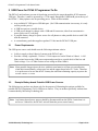
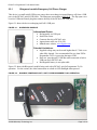
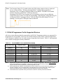
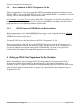
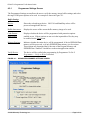
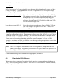
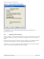
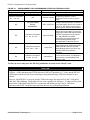
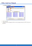
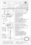
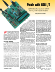
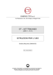
PICKIT™ 2 PROGRAMMER-TO-GO USER GUIDE 1 Introduction The PICkit 2 Programmer-To-Go functionality allows a PIC MCU memory image to be downloaded into the PICkit 2 unit for later programming into a specific PIC MCU. No software or PC is required to program devices once the PICkit 2 unit is set up for Programming-To-Go. A USB power source for the PICkit 2 is all that is needed. Information in this guide covers: USB Power for PICkit 2 Programmer-To-Go Supported PIC MCU Devices Memory Image Size Limitations PICkit 2 Programmer-To-Go Wizard Walkthrough LED Status Codes © 2008 Microchip Technology Inc. Page 1 of 14 PICkit™ 2 Programmer-To-Go Users Guide 2 USB Power for PICkit 2 Programmer-To-Go The PICkit 2 unit hardware prevents it from being powered by the target through the ICSP connector VDD pin. Therefore, it must be powered by a 5 Volt supply through the USB mini-B port at the top of the PICkit 2. Many options exist for providing power. Some of these include: 2.1 Any available PC USB port or USB hub port. (No USB communication is necessary; it is only used to provide power) A USB host port on a portable device. A USB power adapter or charger with a USB mini-B connector, either from an automotive power jack or an AC wall plug. A portable battery charger or power source for cell phones or other portable devices with USB mini-B connector. A custom battery pack that supplies regulated 5 Volts into the PICkit 2 USB port. Power Requirements The USB power source used should meet the following minimum criteria: Is able to supply at least 100mA of current to the PICkit 2 unit. Provides a steady, regulated 4.5 Volt to 5.5 Volt output at a load of 30mA to 100mA. A 160 Ohm resistor between the USB power output and ground gives a quick check of the low end 30mA voltage. Use a 47 Ohm resistor to test voltage at about 100mA. Note: Most portable chargers/power devices with their own batteries will not give an indication when their internal battery voltage gets low and the output drops below 4.5 Volts. Therefore it is up the user to be sure the device’s battery has sufficient remaining capacity to power the PICkit 2 above 4.5 Volts. 2.2 Example Battery-based Portable USB Power Sources The following two products are shown only for the purpose of illustrating the options available for portable PICkit 2 Programmer-To-Go USB power sources. They are neither specifically endorsed nor recommended by Microchip Technology Inc. Note: Any battery-based power sources should be disconnected from the PICkit 2 unit when it is not in use. Otherwise, the PICkit 2 unit will drain the power source battery. © 2008 Microchip Technology Inc. Page 2 of 14 PICkit™ 2 Programmer-To-Go Users Guide 2.2.1 Bluegears b-mobile Emergency Cell Phone Charger This device is a small mini-B USB power source that can recharge its internal battery cell from a USB port via the PICkit 2 mini-B USB cable. The Bluegears part number is BG01145. The flip-open cover reveals a USB mini-B male plug that connects directly to the PICkit 2 unit USB port. Figure 2-1 shows the device recharging itself off a USB port. FIGURE 2-1: BLUEGEARS B-MOBILE Informational Points: Rechargeable via USB port. Small form factor. Connects directly to PICkit 2 unit. Approximate retail cost: $10 (US) Manufacturer website: www.bgears.com Potential Limitations: Supplied voltage may not be much higher than 4.5 Volts even when fully charged. Not recommended for use when PICkit Programmer-To-Go is powering the target VDD. Does not “pass-through” USB data when connected to both a USB port and a PICkit 2 unit. Rechargeable battery is not replaceable. Figure 2-2 shows the Bluegears b-mobile being used with a PICkit 2 unit for Programmer-To-Go operation. For the curious, the white button turns on a built-in LED flashlight when pressed. FIGURE 2-2: B-MOBILE POWERING PICKIT 2 UNIT FOR PROGRAMMER-TO-GO OPERATION © 2008 Microchip Technology Inc. Page 3 of 14 PICkit™ 2 Programmer-To-Go Users Guide 2.2.2 Energizer Energi To Go Mini USB Cell Phone Charger This portable cell charger device runs off two standard AA batteries, and connects via a short cable to the PICkit 2 unit. Several versions of this product are available. The one that is compatible with PICkit 2 is part number CEL2MUSB for “mini USB” cell phones. FIGURE 2-3: ENERGIZER ENERGI TO GO Informational Points: Uses field-replaceable AA batteries. Provides between 5.0 and 5.5 Volt output; suitable for powering a target from PICkit 2. Approximate retail cost: $20 (US) Manufacturer website: www.energitogo.com Potential Limitations: Looks for a battery by pulsing USB voltage output, which may cause PICkit 2 reset problems. See NOTE following. Separate cable may be lost. FIGURE 2-4: ENERGI TO GO POWERING PICKIT 2 PROGRAMMER-TO-GO © 2008 Microchip Technology Inc. Page 4 of 14 PICkit™ 2 Programmer-To-Go Users Guide Note: The Energizer Energi To Go product pulses the USB voltage output to detect a connected device, as shown below. This may cause the PICkit 2’s internal microcontroller to improperly reset, as its Brown Out Reset (BOR) is not enabled. The BOR is not enabled because it interferes with PICkit 2 VDD error detection. Symptoms of the PICkit 2 not coming out of reset properly are that it does not blink the Target LED twice to show it is ready for programming. If this happens, unplug the Energi To Go from the PICkit 2 and plug it back in. Once the blue LEDs on the Energi To Go are blinking, it will not pulse VDD again when reconnected. 3 PICkit 2 Programmer-To-Go Supported Devices All devices in the following families supported by the PICkit 2 Programmer software are supported for Programmer-To-Go operation. However, due to limited memory in the PICkit 2 unit the ProgrammerTo-Go function is limited in the size of the memory image that can be loaded. Table 3-1 lists supported device families and program memory limitations. TABLE 3-1: PROGRAMMER-TO-GO SUPPORTED DEVICES 2 Program Memory Size Limitations Supported Families Supported Parts By Bytes By Maximum Used Address 1 no limit 3 no limit 3 1 no limit 3 no limit 3 Baseline All Midrange PIC18F PIC18 J-Series PIC18 K-Series PIC24 All 1 All 1 All 1 All 1 All dsPIC33 dsPIC30 dsPIC30 SMPS All 1 All 1 All Note 1: 2: 3: 1 107264 bytes 111872 bytes 107264 bytes 106560 bytes 0x1A2FF 0x1B4FF 0x1A2FF 0x1157F 106560 bytes 103872 bytes 3 no limit 0x1157F 0x10E7F 3 no limit Supports all family parts that are supported by the PICkit 2 Programmer application. See menu Help > ReadMe for a list of part supported by the application. Large memory parts are supported; what is limited is the size of the program code that can be programmed by PICkit 2 Programmer-To-Go. Device EEPROM data, UserIDs, and Configuration memory are taken into account in these size limitations. For the sake of simplicity, only the Program Memory size determines if the memory image will fit. Different device families have different memory overhead requirements affecting the maximum size limitation. These families have no practical memory size limit as no devices in the family exceed the actual limit. © 2008 Microchip Technology Inc. Page 5 of 14 PICkit™ 2 Programmer-To-Go Users Guide 3.1 Increasing the Memory for PICkit 2 Programmer-To-Go The memory in the PICkit 2 unit available for Programmer-To-Go code storage may be doubled, thus doubling the Program Memory size limitations shown in Table 3-1. To expand the memory it is necessary to replace the two 24LC512 64KB EEPROMs on the PICkit 2 PCB at U3 and U4 with two 24LC1025-I/SM 128KB EEPROMs. This increases the total EEPROM memory from 128KB to 256KB. It is important to note that the 24LC1025 EEPROMs require the A2 pin tied to VCC for proper operation per the datasheet. The PICkit 2 circuit board has the A2 pads connected to ground. Therefore, when replacing the 24LC512s with 24LC1025s, the A2 pin must be lifted so it does not contact the pad, and wired to the VCC pin of the part. It is also necessary to modify the PICkit 2 Programmer INI file so the software is aware of the expanded EEPROM space. Follow the steps below to complete and use a memory upgrade for your PICkit 2 unit: 1 2 3 4 5 Open the PICkit 2 case by prying it apart with a small flat screwdriver at the three indentations along the seam at a long edge of the case. Remove the 24LC512 serial EEPROMs at reference designators U3 and U4 from the PCB. Lift the A2 pins of two 24LC1025-I/SM serial EEPROMs so they do not contact the circuit board pad when placed on the PCB. Solder the two 24LC1025 EEPROMs in place at U3 and U4 on the PICkit 2 PCB. Solder a wire from the lifted A2 pin to the VCC pin on both 24LC1025 EEPROMs. 6 7 Ensure the PICkit 2 Programmer application is closed Open the INI file (C:\Program Files\Microchip\PICkit 2 v2\PICkit2.ini) in Notepad or another text editor. 8 Find the following line in the INI file: 9 PTGM: 0 Edit the value to 1 as shown below and save and close the INI file PTGM: 1 The PICkit 2 Programmer application will now recognize and use the doubled memory for PICkit 2 Programmer-To-Go in the PICkit 2 unit. It will indicate the INI file edit was successful by displaying the following text at the bottom of the Programmer-To-Go Wizard dialog “Welcome” screen: “256K PICkit 2 upgrade support enabled.” IMPORTANT When replacing the PICkit 2 serial EEPROMs with 24LC1025 devices, the A2 pin of the 24LC1025 devices MUST be lifted and connected to the VCC pin or the 24LC1025 serial EEPROMS will not work. An upgraded 256KB PICkit 2 unit may be used successfully with PICkit 2 Programmer software that is still configured for the default 128K, though any downloads will be limited as per a 128KB unit. However, the reverse is not true. A PICkit 2 unit with the default 128KB may not be used successfully with PICkit 2 Programmer software that is configured to use the 256KB upgrade, even if the code size is within the 128KB limits. © 2008 Microchip Technology Inc. Page 6 of 14 PICkit™ 2 Programmer-To-Go Users Guide 3.2 Other Limitations of PICkit 2 Programmer-To-Go PICkit 2 Programmer-To-Go only supports the WRITE programming operation. It cannot be set up to READ, VERIFY (only), or BLANK CHECK a device. Note that an ERASE can essentially be set up by leaving all the PICkit 2 Programmer software buffers blank. If Programmer > Verify on Write is checked, then PICkit 2 Programmer-To-Go will verify the device it programs. The PICkit 2 Programmer-To-Go verify is accomplished by calculating a checksum of the programmed device and comparing it with an expected value. 3.2.1 PIC18F: Preserve EEPROM Data on Write Limitation When programming a device with the EEPROM Data memory region “Enabled” checkbox unchecked, PICkit 2 will write Program Memory, User IDs, and Configuration words but preserve the existing EEPROM Data memory in the device. For most PIC18F devices, this may be done with PICkit 2 Programmer-To-Go. However, on some of the PIC18F devices the EEPROM Data memory must be read from the device first, then reprogrammed with the other memory regions. For these devices PICkit 2 Programmer-ToGo does not support preserving the existing device EEPROM Data. An error will be given in the software if the user attempts to set up such an operation for an affected device. 4 Setting up PICkit 2 for Programmer-To-Go Operation Before downloading a memory image to PICkit 2 for Programmer-To-Go operation, the PICkit 2 Programmer software options and buffers should be set up as desired during Programmer-To-Go operation. In fact, it is highly recommended to test programming a target device from the software first, with all desired options, to ensure the device programs as expected before downloading an image to Programmer-To-Go. © 2008 Microchip Technology Inc. Page 7 of 14 PICkit™ 2 Programmer-To-Go Users Guide 4.1 Set Up Programming Data and Options A checklist of steps includes: 1 Ensure the PIC MCU part number you wish to program is the active device. Use the Device Family menu to select the proper family first. It must show up at the top of the Device Configuration area of the PICkit 2 window. If a target part is not available to connect to, select Programmer > Manual Device Select. This allows the part number to be selected from a combo-box. 2 Load the memory image to be programmed into the PICkit 2 buffers. This may be done via File > Import Hex or by a READ operation on an existing device. 3 Set the PICkit 2 Programmer software options as desired. The following options affect Programmer-To-Go operation. For detailed information on an option, please consult the PICkit 2 User’s Guide via Help > PICkit 2 User’s Guide Programmer > Verify on Write Programmer > Hold Device in Reset Tools > Enable Code Protect Tools > Enable Data Protect Tools > Use VPP First Program Entry Tools > Fast Programming The “VDD PICkit 2” device VDD box determines the provided VDD voltage, if PICkit 2 will power the device. 4 4.2 Test programming on a target device from the PICkit 2 Programmer software. The Programmer-To-Go Setup Wizard Once the memory image and programming options for intended target device are set up and tested, start the Programmer-To-Go Setup Wizard via Programmer > PICkit 2 Programmer-To-Go… The wizard dialog will open to the “Welcome” screen. Click Next > to go to the “Programmer Settings” screen. © 2008 Microchip Technology Inc. Page 8 of 14 PICkit™ 2 Programmer-To-Go Users Guide 4.2.1 Programmer Settings Screen The Programmer Settings screen allows the user to verify the memory image buffer settings, and select the target VDD power options to be used. An example is shown in Figure 4-1. Buffer Settings Device: Shows the selected target device. OSCCAL and BandGap values will be preserved on applicable devices. Buffer data source: Displays the source of the current buffer memory image to be used. Code Protect: Data Protect: Displays whether the device will be programmed with protection options enabled or not. If these options are not set in the imported hex file, they may be enabled via the Tools menu. Memory Regions: Indicates whether the entire device will be programmed, if device EEPROM Data memory will be preserved, or if only EEPROM Data memory is to be written. These options are determined the by the state of the Program Memory and EEPROM Data “Enabled” checkboxes on the main application window. Verify Device: The device will be verified after programming by Programmer-To-Go if Programmer > Verify on Write is checked. FIGURE 4-1: WIZARD PROGRAMMER SETTINGS SCREEN © 2008 Microchip Technology Inc. Page 9 of 14 PICkit™ 2 Programmer-To-Go Users Guide Power Settings PICkit 2 Programmer-To-Go may optionally power the target device, though usually a target will have its own power supply. It is recommended to use PICkit 2 Programmer-To-Go with a powered target instead of powering it off PICkit 2. Target has its own power supply: Select this option if the target will not be powered from PICkit 2. The minimum supported voltage for programming the device will be displayed. If the device has a high Bulk Erase voltage but supports a low voltage row erase method, a checkbox will be present as shown in Figure 4-1. Check the box if the target VDD will be below the voltage shown. Power the target from PICkit 2: Select this option to power the target from the PICkit 2 VDD pin. The VDD voltage is set by the “VDD PICkit 2” Voltage box in the main application window. CAUTION When powering a target from PICkit 2, ensure the USB power source provides sufficient Voltage and current for programming the device. Depending on the power source used, PICkit 2 may not be able to provide the desired VDD Voltage to the target. The maximum VDD the PICkit 2 can output is about 200 to 300mV below the USB power source voltage. Target current and capacitance limitations are the same using Programmer-To-Go as for USB operation. A maximum of 25mA is available to power the target, and target capacitance must not slow the VDD rise time to longer than 500us. Note: If the Low Voltage Row Erase method is used with a target device, code protected devices cannot be programmed. Programming a protected device requires a Bulk Erase operation at or above the given VDD threshold. If all Programmer Settings shown in the dialog are appropriate, click Next >. 4.2.2 Download to PICkit 2 Screen This screen provides a summary of the settings from the previous screen, and indicates whether or not Tools > Fast Programming and Programmer > Hold Device in Reset are enabled. For most situations, both these options should be enabled. © 2008 Microchip Technology Inc. Page 10 of 14 PICkit™ 2 Programmer-To-Go Users Guide FIGURE 4-2: WIZARD DOWNLOAD SETTINGS SCREEN Click Download to store the memory image and settings in the PICkit 2 unit and place it in Programmer-To-Go mode. 4.2.3 Download to PICkit 2 Complete The screen in Figure 4-3 will appear when the download is complete. The PICkit 2 unit’s “Target” LED should now be blinking twice in succession to indicate it is in Programmer-To-Go mode and ready to program. Disconnect the PICkit 2 from the PC USB port. When any USB power source is applied, the PICkit 2 unit will power up in Programmer-To-Go mode, indicated by the blinking “Target” LED. Click Next > to view a wizard screen giving examples of Programmer-To-Go error codes (covered in Section 5 of this document) or click Exit to close the Wizard dialog. © 2008 Microchip Technology Inc. Page 11 of 14 PICkit™ 2 Programmer-To-Go Users Guide FIGURE 4-3: WIZARD DOWNLOAD COMPLETE SCREEN 5 Using PICkit 2 Programmer-To-Go To use PICkit 2 Programmer-To-Go to program a target device once it has been set up, follow the steps below. 1 Connect a USB power source as discussed in Section 2 of this document to the PICkit 2 unit. 2 Ensure the PICkit 2 “Power” LED is lit, and the “Target” LED is blinking twice in succession to indicate the unit is in Programmer-To-Go mode and ready to program. 3 Connect the PICkit 2 unit ICSP connector to the target. Ensure the target is powered properly if not powering from PICkit 2. 4 Press the PICkit 2 pushbutton to begin programming. During the programming operation the PICkit 2 “Busy” LED will remain lit continuously. The “Target” LED will light if powering from PICkit 2, but will remain off if the target has its own power supply. When the programming operation is complete, the PICkit 2 unit will provide feedback on the operation via the unit LEDs. See table 5-1 for a list of display codes. © 2008 Microchip Technology Inc. Page 12 of 14 PICkit™ 2 Programmer-To-Go Users Guide FIGURE 5-1: PROGRAMMER-TO-GO PROGRAMMING OPERATION FEEDBACK CODES LED States Interpretation Target LED (Yellow) Busy LED (Red) Code Description 2 blinks in succession: Off Success / Ready Continuous Rapid Blinking: VDD / VPP Error Off Off Off Off 2 blinks in succession: 3 blinks in succession: 4 blinks in succession: Device ID Error Verify Error Internal Error No errors were encountered during the programming operation. PICkit 2 Programmer-To-Go is ready to program again. PICkit 2 was unable to set the VDD or VPP voltage to the expected value. If PICkit 2 is not providing VDD, then the error must be a VPP error. See Chapter 3 of the PICkit 2 Users Guide for VDD and VPP information. PICkit 2 received an unexpected Device ID from the target. Ensure the target part matches that selected when PICkit 2 Programmer-To-Go was set up. May indicate a bad ICSP connection preventing PICkit 2 from communicating with the target. Not applicable to Baseline devices. The target did not Verify successfully after programming. Ensure the target VDD meets the minimum required. With Baseline devices, this error may indicate ICSP communication problems. An unexpected internal ProgrammerTo-Go error occurred. If it happens a second time, try downloading to the PICkit 2 again. To clear an error code, press the PICkit 2 pushbutton to return to the “Ready” state. CAUTION When the “Target” LED blinks, approximately 2 Volts will appear on the PICkit 2 ICSP connector VDD pin. As the minimum target VDD allowed for PICkit 2 operation is 2.5 Volts, and the PICkit 2 VDD output contains a diode to prevent backpowering from the target VDD, this situation is not a concern. However, when PICkit 2 is set up to provide VDD to the target, the target will see the 2 Volt pulses while the LED is blinking. Ensure this will not cause a problem for the target. If a short or heavy load exists on the VDD signal when PICkit 2 is connected and blinking it may cause a VDD Error. Disconnect the PICkit 2 from the target and clear the error by pressing the pushbutton. © 2008 Microchip Technology Inc. Page 13 of 14 PICkit™ 2 Programmer-To-Go Users Guide 5.1 Exiting Programmer-To-Go Mode To exit a PICkit 2 unit from Programmer-To-Go mode, plug into a PC USB port and connect to (use) the unit with either the PICkit 2 Programmer software, PK2CMD, or MPLAB IDE. In the PICkit 2 Programmer software, use Tools > Check Communications to connect to a PICkit 2 unit. Note: Programmer-To-Go mode cannot be exited while the Busy LED is blinking to indicate an error. Press the pushbutton to clear the error before attempting to connect. © 2008 Microchip Technology Inc. Page 14 of 14