1
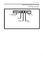
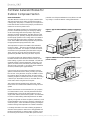
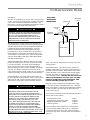
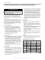
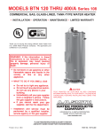
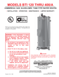
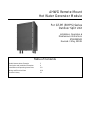
AHWG Remote Mount
Hot Water Generator Module
For GT-PE (50YPS) Series
Outdoor Split Unit
Installation, Operation &
Maintenance Instructions
97B0080N02
Revised: 3 May, 2010B
Table of Contents
Model Nomenclature Example
3
Description and Installation Examples
4
Installation and Operating Instructions
5-8
Wiring and Electrical Data
9-10
Revision History
12
This page has been intentionally left blank.
Remote HWG
R e v i s e d : 3 M a y, 2 0 1 0
Model Nomenclature: for Remote
Hot Water Generator
1
2
3
5
4
6
7
8
9
AHWG 1 A A C S
Accessory
Future
AHWG = Accessory Remote
Hot Water Generator
CS = Standard
Size
1 = Standard
Revision
A = Current Revision
Voltage
A = 115/60/1
G = 208-230/60/1
3
Remote HWG
R e v i s e d : 3 M a y, 2 0 1 0
Hot Water Generator Module For
Outdoor Compressor Section
General Information
The HWG Module consists of an all-copper, vented doublewall heat exchanger and a water-cooled bronze water circulating pump. The pump is controlled by a microprocessor
in the HWG module. Power for the pump is provided from a
remote 115 or 230 vac power source.
potential cost of frequent maintenance may offset or exceed
any savings. Consult unit IOM for scaling potential tests.
The HWG (Hot Water Generator) or desuperheater option
provides considerable operating cost savings by utilizing
excess heat energy from the heat pump to help satisfy
domestic hot water requirements. The HWG may be active
throughout the year, providing virtually free hot water when
the heat pump operates in the cooling mode or hot water at
the COP of the heat pump during operation in the heating
mode. Actual HWG water heating capacities are provided in
the appropriate heat pump performance data.
Figure 1: Typical HWG Installation (Outdoor Compressor
Section)
Shut-off
Valve #1
Shut-off
Valve #4
8SSHU
HOHPHQWWR
120 - 130°F
[49 - 54°C]
Shut-off
Valve #3
The temperature set point of the HWG is field selectable
to 125°F or 150°F . The 150°F set point allows more heat
storage from the HWG. For example, consider the amount
of heat that can be generated by the HWG when using the
125°F set point, versus the amount of heat that can be
generated by the HWG when using the 150°F set point.
In a typical 50 gallon two-element electric water heater
the lower element should be turned down to 100°F, or the
lowest setting, to get the most from the HWG. The tank will
eventually stratify so that the lower 80% of the tank, or 40
gallons, becomes 100°F (controlled by the lower element).
The upper 20% of the tank, or 10 gallons, will be maintained
at 125°F (controlled by the upper element).
Cold Inlet from
Domestic supply
+RW2XWOHW
WRKRPH
3RZHUHG
:DWHU
+HDWHU
Shut Off
Valve #2
,QVXODWHGZDWHUOLQHV
µ2'IWPD[LPXPRQHZD\PHWHUV
>PP2'PHWHUVPD[LPXP@
Figure 2: HWG Double Tank Installation (Outdoor Compressor Section)
Hot Outlet to
house
Cold Inlet
Hot Outlet
Cold Inlet from
Domestic supply
Shut-off
Valve #1
Using a 125°F set point, the HWG can heat the lower 40
gallons of water from 100°F to 125°F, providing up to 8,330
btu’s of heat. Using the 150°F set point, the HWG can heat
the same 40 gallons of water from 100°F to 150°F and the
remaining 10 gallons of water from 125°F to 150°F, providing
a total of up to 18,743 btu’s of heat, or more than twice as
much heat as when using the 125°F set point.
Upper element to 130°F [54°C]
(or owner preference)
Shut-off
Valve #4
Shut-off
Valve #3
Powered
Water Heater
Lower element to 120°F [49°C]
Unpowered
Water Heater
Shut Off
Valve #2
Field Supplied 3/4” brass nipple and “T”
Insulated water lines - 5/8” OD, 50 ft maximum (one way)
[16mm OD, 15 meters maximum]
This example ignored standby losses of the tank. When
those losses are considered the additional savings are even
greater.
Electric water heaters are recommended. If a gas, propane,
or oil water heater is used, a second preheat tank must be
installed (Figure 2). If the electric water heater has only a
single center element, the dual tank system is recommended
to insure a usable entering water temperature for the HWG.
Typically a single tank of at least 52 gallons (235 liters) is used
to limit installation costs and space. However, a dual tank, as
shown in Figure 2, is the most efficient system, providing the
maximum storage and temperate source water to the HWG.
It is always advisable to use water softening equipment on
domestic water systems to reduce the scaling potential and
lengthen equipment life. In extreme water conditions, it may
be necessary to avoid the use of the HWG option since the
4
/RZHU
HOHPHQWWR
100 - 110°F
[38 - 43°C]
W a t e r- S o u r c e H e a t i n g a n d C o o l i n g S y s t e m s
Remote HWG
R e v i s e d : 3 M a y, 2 0 1 0
Hot Water Generator Module Refrigeration Installation
For Outdoor Compressor Section Only
Location/Mounting
The HWG module should be mounted indoors and as close
to the heat pump outdoor section as possible, in order to
minimize the length of refrigerant run. It is recommended that
the HWG module be mounted above the system compressor
in order to promote proper oil movement and drain-down.
This means that the HWG module can be wall mounted
in any orientation except for stubs up. Mounting should be
accomplished by fastening the HWG module cabinet to the
wall or other selected vertical surface. Mounting holes are
provided at the rear of the unit. Any fastener suitable for supporting a 12 pound [5.4] vertical load is acceptable.
SPECIAL NOTE: The selected mounting location and
orientation must allow the circulator pump to be positioned
with the motor shaft horizontal. DO NOT install the Heat
Recovery Unit flat on its back.
Refrigerant Line Installation
Before starting the installation into the refrigerant circuit,
inspect and note the condition and performance of the heat
pump. Disconnect power to the heat pump outdoor unit. Any
system deficiencies must be corrected prior to installing the
HWG module. Addition of the HWG will not correct system
problems. Record the suction and discharge pressures
and compressor amperage draw. These may be used for
comparison with system operation after the refrigerant line
installation is complete.
NOTICE! Make sure the compressor discharge line is
connected to the “Hot Gas In” stub on the Hot Water
Generator.
WARNING!
WARNING! The HWG module is an appliance that
operates in conjunction with the heat pump system, the
hot water system and the electrical system. Installation
should only be performed by skilled technicians with
appropriate training and experience. The installation must
be in compliance with local codes and ordinances. Local
plumbing and electrical building codes take precedence
over instructions contained herein. The Manufacturer
accepts no liability for equipment damaged and/or personal
injury arising from improper installation of the HWG module.
CAUTION!
CAUTION! The HWG module must be installed in an area
that is not subject to freezing temperatures.
CAUTION!
CAUTION! Locate Refrigerant lines to avoid accidental
damage by lawnmowers or children.
Install the Add-On HWG Kit
Locate the HWG as close to the water heater as possible.
Install the lineset to the desuperheater valves in the outdoor compressor section and the refrigerant line connections on the HWG. Maximum length should be 30 feet one
way. Evacuate the lineset to 500 microns through the hot
gas valves in the outdoor unit. Open the HWG valves in the
compressor section up fully (and close the desuperheater
bypass valve). See Figures 3a through 3d. Check the lineset
for leaks. Verify that lineset tubing is completely insulated
with a minimum 1/2” thick closed cell and painted to prevent
deterioration of the insulation due to ultra violet light and
weather. Make the connections with high temperature solder
or brazing rod. The recommended line size is dependent on
the one way distance between the Hot Water Generator and
the compressor; and the size of the system. Use Figure 4 as
a guideline.
5
Remote HWG
R e v i s e d : 3 M a y, 2 0 1 0
Hot Water Generator Module Installation
Outdoor Compressor Section Only
Figure 3a: Outdoor Compressor Section HWG Installation
Figure 3c: HWG Service Valves
Refr
to HWG
HWG
Bypass
Valve
Refr from
HWG
Refr to
HWG
HWG
Line Valves
Refr from
HWG
Fully Insulated
Lines to the HWG
Figure 3b: Remote HWG Module
Figure 4: HWG Refrigerant Line Sizing
Control
Board
HWG
Refr Out
HWG
Water Out
HWG
Refr In
16.2”
Circulator
High Voltage
Line Set Size
1/2” OD
5/8” OD
3/4” OD
2 Ton
Up to 16 ft.
[4.9m]
Up to 30 ft.
[9.1m]
N/A
3 Ton
Up to 9 ft.
[2.7m]
Up to 25 ft.
[7.6m]
Up to 30 ft.
[9.1m]
4 Ton
Up to 5 ft.
[1.5m]
Up to 13 ft.
[4.0m]
Up to 30 ft.
[9.1m]
5 Ton
N/A
Up to 9 ft.
[2.7m]
Up to 25 ft.
[7.6m]
7.1”
Low
HWG
Voltage
Water
In
11.1”
Capacity
HWG
Water In
Figure 3d: HWG Bypass Valve
As a guideline add 1.0 oz. of refrigerant for the heat exchanger plus 1.0 oz. for each 10 ft of 1/2” OD refrigerant
line, if the weighed charge method is used (28g for the heat
exchanger plus 9g per meter of 1/2” OD refrigerant line).
Valve Open
(HWG Bypassed)
6
Valve Closed
(HWG Activated)
W a t e r- S o u r c e H e a t i n g a n d C o o l i n g S y s t e m s
Remote HWG
R e v i s e d : 3 M a y, 2 0 1 0
Hot Water Generator Module
Installation
The HWG is controlled by two sensors and a microprocessor
control. One sensor is located on the compressor discharge
line to sense the discharge refrigerant temperature. The
other sensor is located on the HWG heat exchanger’s “Water
In” line to sense the potable water temperature.
ANTI-SCALD
VALVE PIPING
CONNECTIONS
ANTI-SCALD
VALVE
WARNING!
The microprocessor control monitors the refrigerant and
water temperatures to determine when to operate the HWG.
The HWG will operate any time the refrigerant temperature
is sufficiently above the water temperature. Once the
HWG has satisfied the water heating demand during a
heat pump run cycle, the controller will cycle the pump at
regular Intervals to determine if an additional HWG cycle
can be utilized. The microprocessor control Includes 3 DIP
switches, SW10 (HWG PUMP TEST), SW11 (HWG TEMP),
and SW12 (HWG STATUS).
SW10 HWG PUMP TEST. When this switch is in the “ON”
position, the HWG pump is forced to operate even if there
is no call for the HWG. This mode may be beneficial to
assist in purging the system of air during Initial start up.
When SW10 is in the “OFF” position, the HWG will operate
normally. This switch is shipped from the factory in the
“OFF” (normal) position. NOTE; If left in the “On” position for
5 minutes, the pump control will revert to normal operation.
SW11 HWG TEMP. The control setpoint of the HWG can
be set to either of two temperatures, 125°F or 150°F. When
SW11 is in the “ON” position the HWG setpoint is 150°F.
When SW11 is in the “OFF” position the HWG setpoint is
WARNING!
WARNING! USING A 150°F SETPOINT ON THE
HWG WILL RESULT IN WATER TEMPERATURES
SUFFICIENT TO CAUSE SEVERE PHYSICAL INJURY
IN THE FORM OF SCALDING OR BURNS, EVEN
WHEN THE HOT WATER TANK TEMPERATURE
SETTING IS VISIBLY SET BELOW 150°F. THE
150°F HWG SETPOINT MUST ONLY BE USED ON
SYSTEMS THAT EMPLOY AN APPROVED ANTISCALD VALVE (MANUFACTURER PART NUMBER
AVAS4) AT THE HOT WATER STORAGE TANK
WITH SUCH VALVE PROPERLY SET TO CONTROL
WATER TEMPERATURES DISTRIBUTED TO ALL HOT
WATER OUTLETS AT A TEMPERATURE LEVEL THAT
PREVENTS SCALDING OR BURNS!
HOT WATER
TO HOUSE
C
M
H
8” MAX
WARNING! UNDER NO CIRCUMSTANCES SHOULD
THE SENSORS BE DISCONNECTED OR REMOVED
AS FULL LOAD CONDITIONS CAN DRIVE HOT
WATER TANK TEMPERATURES FAR ABOVE SAFE
TEMPERATURE LEVELS IF SENSORS HAVE BEEN
DISCONNECTED OR REMOVED.
CHECK VALVE
COLD WATER
SUPPLY
WATER HEATER
125°F. This switch Is shipped from the factory in the “OFF”
(125°F) position.
SW12 HWG STATUS. This switch controls operation of
the HWG. When SW12 is in the “ON” position the HWG is
disabled and will not operate. When SW12 is in the “OFF”
position the HWG is in the enabled mode and will operate
normally. This switch is shipped from the factory in the
“ON” (disabled) position. CAUTION: DO NOT PLACE THIS
SWITCH IN THE ENABLED POSITION UNITL THE HWG
PIPING IS CONNECTED, FILLED WITH WATER, AND
PURGED OR PUMP DAMAGE WILL OCCUR.
When the control is powered and the HWG pump output
is not active, the status LED (AN1) will be “On”. When the
HWG pump output is active for water temperature sampling
or HWG operation, the status LED will slowly flash (On 1
second, Off 1 second).
If the control has detected a fault, the status LED will flash a
numeric fault code as follows:
Hot Water Sensor Fault
Compressor Discharge sensor fault
High Water Temperature (>160ºF)
Control Logic Error
1 flash
2 flashes
3 flashes
4 flashes
Fault code flashes have a duration of 0.4 seconds with
a 3 second pause between fault codes. For example, a
“Compressor Discharge sensor fault” will be four flashes
0.4 seconds long, then a 3 second pause, then four flashes
again, etc.
7
Remote HWG
R e v i s e d : 3 M a y, 2 0 1 0
Hot Water Generator Module - Domestic Water Installation
WARNING!
Warning! Use extreme caution when working around
the microprocessor control as it contains line voltage
connections that presents a shock hazard that can
cause severe injury or death!
The heat pump, water piping, HWG, and hot water tank
should be located where the ambient temperature does
not fall below 50°F [10°C]. Keep water piping lengths at a
minimum. DO NOT use a one way length greater than 50 ft.
(one way) [15 m].
All installations must be in accordance with local codes. The
installer is responsible for knowing the local requirements,
and for performing the installation accordingly. DO NOT
connect the pump wiring until “Initial Start-Up” section,
below. Powering the pump before all installation steps are
completed may damage the pump.
Water Tank Preparation
1. Turn off power or fuel supply to the hot water tank.
2. Connect a hose to the drain valve on the water tank.
3. Shut off the cold water supply to the water tank.
4. Open the drain valve and open the pressure relief valve
or a hot water faucet to drain tank.
5. When using an existing tank, it should be flushed with
cold water after it is drained until the water leaving the
drain hose is clear and free of sediment.
6. Close all valves and remove the drain hose.
7. Install HWG water piping.
HWG Water Piping
1. Using at least 5/8” [16mm] O.D. copper, route and install
the water piping, valves and air vent as shown in Figures
1 or 2. Install an approved anti-scald valve if the 150°F
HWG setpoint is or will be selected. An appropriate
method must be employed to purge air from the HWG
piping. This may be accomplished by flushing water
through the HWG (as In Figures 1 and 2) or by Installing
an air vent at the high point of the HWG piping system.
2. Insulate all HWG water piping with no less than 3/8”
[10mm] wall closed cell insulation.
3. Open both shut off valves and make sure the tank drain
valve is closed.
Water Tank Refill
1. Close valve #4. Ensure that the HWG valves (valves #2
and #3) are open. Open the cold water supply (valve #1)
to fill the tank through the HWG piping. This will purge air
from the HWG piping.
2. Open a hot water faucet to vent air from the system until
water flows from faucet; turn off faucet. Open valve #4.
3. Depress the hot water tank pressure relief valve handle to
ensure that there is no air remaining in the tank.
4. Inspect all work for leaks.
8
5. Before restoring power or fuel supply to the water heater,
adjust the temperature setting on the tank thermostat(s)
to insure maximum utilization of the heat available from
the refrigeration system and conserve the most energy.
On tanks with both upper and lower elements and
thermostats, the lower element should be turned down
to 100°F [38°C] or the lowest setting; the upper element
should be adjusted to 120-130°F [49-54°C]. Depending
upon the specific needs of the customer, you may want
to adjust the upper element differently. On tanks with a
single thermostat, a preheat tank should be used (Fig 2).
6. Replace access cover(s) and restore power or
fuel supply.
Initial Start-Up
1. Make sure all valves in the HWG water circuit are fully
open.
2. Make electrical connections (power and low voltage)
as shown on the HWG wiring diagram. Example wiring
diagrams and an electrical data table are included in this
document (See Figures 5-8).
3. Turn the heat pump power and remote HWG power “off”
and switch dip switch SW12 on the HWG controller to the
“off” (enabled) position to activate the HWG.
4. Allow the unit to operate for 20 to 30 minutes insure that
it is functioning properly.
5. The HWG pump should not run if the compressor is not
running.
6. The temperature difference between the water entering
and leaving the HWG should be approximately 5-10 °F
[3-6 °C].
Servicing
1. Always turn dip switch SW12 on the HWG controller to
the “on” (disabled) position to deactivate the HWG when
servicing the outdoor compressor section.
HWG Water Piping Size and Length
Unit
Nominal
Tonnage
Nominal
HWG Flow
(gpm)
1/2" Copper
(max length*)
3/4" Copper
(max length*)
1.5
0.6
50
-
2.0
0.8
50
-
2.5
1.0
50
-
3.0
1.2
50
-
3.5
1.4
50
-
4.0
1.6
45
50
5.0
2.0
25
50
6.0
2.4
10
50
*Maximum length is equivalent length one way of type L copper.
W a t e r- S o u r c e H e a t i n g a n d C o o l i n g S y s t e m s
Remote HWG
R e v i s e d : 3 M a y, 2 0 1 0
Electrical - Wiring
Figure 5: HWG Module Wiring 230 Volt
CONDENSER
CONDENSER
CONDENSER
HWG Module
Figure 6: HWG Module Wiring 115 volt
HWG Module Wiring - For
“Outdoor” Compressor Section
The HWG module should be wired to
a power supply as shown in Figure
5 or 6. A safety disconnect should
be installed at the HWG module as
required by code to allow servicing
of the module. DO NOT energize
the pump until all HWG piping is
completed and air is purged from
the water piping to avoid running the
pump “dry”.
E
E
E
Figure 7: HWG Module Electrical Data
HWG
Module
Voltage
Pump
FLA
Total FLA
Min
Circuit
Amps
Min Wire
Size
AHWG1AACS
115/60/1
0.52
0.52
1.20
14 ga.
AHWG1AGCS
208/230/60/1
0.40
0.40
0.90
14 ga.
WARNING!
WARNING! To avoid possible injury or death due to
electrical shock, open the power supply disconnect switch
and secure it in an open position during installation.
CAUTION!
CAUTION! Use only copper conductors for field installed
electrical wiring. Unit terminals are not designed to accept
other types of conductors.
9
Remote HWG
R e v i s e d : 3 M a y, 2 0 1 0
Electrical - Wiring
Figure 8: Low Voltage Field Wiring
WARNING!
WARNING! To avoid possible injury or death due to
electrical shock, open the power supply disconnect switch
and secure it in an open position during installation.
10
CAUTION!
CAUTION! Use only copper conductors for field installed
electrical wiring. Unit terminals are not designed to accept
other types of conductors.
W a t e r- S o u r c e H e a t i n g a n d C o o l i n g S y s t e m s
Remote HWG
R e v i s e d : 3 M a y, 2 0 1 0
Notes:
11
Remote HWG
R e v i s e d : 3 M a y, 2 0 1 0
Revision History
Date
Page #
Description
1 July, 10
Various
Warranty, Nomenclature, Unit Photos Updated
3 May, 10
4
HWG Piping Drawings Revised
3 Nov., 09
All
First Published
ISO 9001:2000
Certified
Quality: First & Always
7300 S.W. 44th Street
*97B0080N02*
Oklahoma City, OK 73179
Phone: 405-745-6000
Fax: 405-745-6058
97B0080N02
The Manufacturer works continually to improve its products. As a result, the design and specifications of each product at the time for order may
be changed without notice and may not be as described herein. Please contact the Manufacturer’s Customer Service Department at 1-405-7456000 for specific information on the current design and specifications. Statements and other information contained herein are not express warranties and do not form the basis of any bargain between the parties, but are merely the Manufacturer’s opinion or commendation of its products.
The management system governing the manufacture of the Manufacturer’s products is ISO 9001:2000 certified.
© LSB, Inc. 2009
12
W a t e r- S o u r c e H e a t i n g a n d C o o l i n g S y s t e m s
Revised: 1 May, 2010B