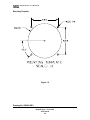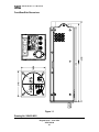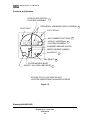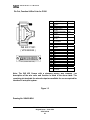
1
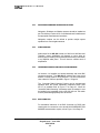
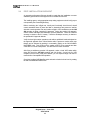
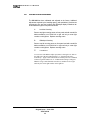
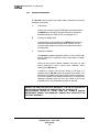
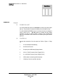
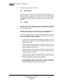
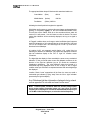
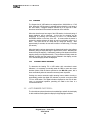
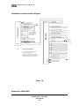
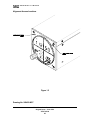
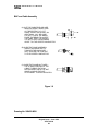
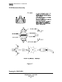
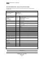
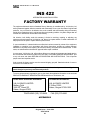
1
Original Issue
AVIONICS LIMITED
INS 422
Integrated
Navigation System
Installation/Owners Manual
VPN 701034
June 2001
AVIONICS
LIMITED
INS 422 INTEGRATED NAVIGATION SYSTEM
Installation/Owners Manual
June 2001
© 2001 by VAL Avionics, Ltd. All Rights Reserved
Printed in the U. S. A.
VAL Avionics, Ltd. will continually improve product quality and performance. Information contained
in this document is subject to change at any time without notice. This document may not be
reproduced or transmitted by any means without consent of VAL Avionics, Ltd.
Is a registered trademark of VAL Avionics Ltd.
AVIONICS, LTD
P.O. Box 13025
Salem, Oregon 97309
(503) 370-9429
INS 422 Installation/Owners Manual
Original Issue – June 2001
VPN 701034
1
AVIONICS
LIMITED
TABLE OF CONTENTS
SECTION I
General Information
Paragraph
1.1
INTRODUCTION
1.2
DESCRIPTION OF EQUIPMENT
1.3
TECHNICAL CHARACTERISTICS
1.4
UNITS AND ACCESSORIES REQUIRED (SUPPLIED)
1.5
ACCESSORIES REQUIRED (NOT SUPPLIED)
1.6
LICENSE REQUIREMENTS
1.7
STATEMENT OF COMPLIANCE
INS 422 Installation/Owners Manual
Original Issue – June 2001
VPN 701034
2
AVIONICS
LIMITED
SECTION II
Installation
Paragraph
2.1
GENERAL INFORMATION
2.2
UNPACKING AND INSPECTING
2.3
EQUIPMENT INSTALLATION
2.3.1
Avionics Cooling Requirements for Panel Mounted Equipment
2.3.2
Pre-Installation Information
2.3.3
Antenna Installation
2.3.4
Audio Interface
2.3.5
Harness Assembly and Installation Hardware
2.4
Post Installation Check
2.4.1
Post Installation Adjustments
2.4.2
Periodic Maintenance
INS 422 Installation/Owners Manual
Original Issue – June 2001
VPN 701034
3
AVIONICS
LIMITED
SECTION III
Operation
Paragraph
3.1
POWER ON UNIT
3.2
CONTROLS AND ACCESSORIES OF THE FRONT PANEL
3.3
OPERATION
3.4
AUTO-DIMMER PHOTOCELL
ILLUSTRATIONS
Figure
1 . 0
M O U N T I N G
T E M P L A T E
1 . 1
F R O N T - R E A R - S I D E
1 . 2
F U N C T I O N S
1 . 3
W I R E
1 . 4
I N S T A L L A T I O N
1 . 5
A L I G N M E N T
1 . 6
B N C
1 . 7
P 1 2 0 1
A N D
C O L O R
A N D
A N D
D I M E N S I O N S
O P E R A T I O N
F U N C T I O N
I N T E R C O N N E C T
A C C E S S
C A B L E
D I A G R A M
L O C A T I O N S
A S S E M B L Y
M E C H A N I C A L
A S S E M B L Y
Revision History
APPENDIX A
E N V I R O N M E N T A L
Q U A L I F I C A T I O N
F O R M
APPENDIX B
M A N U F A C T U R E R S
W A R R A N T Y
S T A T E M E N T
INS 422 Installation/Owners Manual
Original Issue – June 2001
VPN 701034
4
AVIONICS
LIMITED
I
Section
General
Information
1.1
Paragraph
INTRODUCTION
This manual provides information relative to the physical, mechanical and
electrical characteristics of the INS 422 Integrated Navigation System.
Follow the procedures outlined in this manual for successful installation and
designed performance.
1.2
DESCRIPTION OF EQUIPMENT
The INS 422 Integrated Navigation System is a quality manufactured panel
mounted digital synthesized instrument approach receiver covering the
aviation frequencies for Localizer Receiver 108.1 – 111.975 MHz, Glideslope
Receiver 329.15 – 335.0 MHz, Marker Receiver 75 MHz and VOR navigation
receiver frequencies 108.0 – 117.95 MHz.
INS 422 Installation/Owners Manual
Original Issue – June 2001
VPN 701034
5
AVIONICS
1.3
LIMITED
TECHNICAL SPECIFICATIONS
SPECIFICATIONS
CHARACTERISTICS
Environmental: (RTCA/DO160D)
VOR
Localizer
Glideslope
Marker Beacon
RTCA/DO-196
RTCA/DO-195
RTCA/DO-192
RTCA/DO-143 Class B
Physical Dimensions:
Height
Width
Depth
3.32 inches (8.44cm)
3.45 inches (8.76cm)
10.84 inches (27.53cm)
Weight:
3.2 pounds (1.5 kg)
Mounting:
Panel mounted, no shock mounting required
Temperature Range:
-20 to +55 Celsius with short time operations at
+70 Celsius
Power Requirements:
Voltage
Current
Receiver:
VHF Frequency (VOR/LOC)
Sensitivity
Channel Spacing (VOR/LOC)
UHF Frequency (Glideslope)
Sensitivity
Channel Spacing (Glideslope)
Marker Receiver
AGC Characteristics
External Outputs:
Audio Output
13.75 VDC (27.5 VDC with Voltage Reducer
VPN 807000)
1.8 Amp Receive
108.00 to 117.95 MHz
2 µV to provide 50% Standard Deflection
50 Khz
329.15 to 335.0 MHz
20 µV to provide 50% Standard Deflection
150 Khz
75 MHz
From 10 µV to 200 µV the audio level will not
vary more than 3db.
10mv into a 600 ohm load
CDI Left/Right
CDI Up/Down
CDI Glideslope Flag
CDI VOR/LOC Flag
FCC Identifier
Manufacturer’s Model Number
Part Number
150mv into 1K Load
150mv into 1K Load
EZNINS422
INS 422
VPN 801004
INS 422 Installation/Owners Manual
Original Issue – June 2001
VPN 701034
6
AVIONICS
LIMITED
INS 422 Installation/Owners Manual
Original Issue – June 2001
VPN 701034
7
AVIONICS
1.4
UNITS AND ACCESSORIES SUPPLIED
1.4.1
INS 422 INSTALLATION KIT (VPN 651001)
VPN
501067
550022
550062
701034
750014
501057
501117
1.5
QUANTITY
6
3
10
1
1
2
1
VHF Navigation Antenna
UHF Glide Slope Antenna or VOR Coupler/GS Diplexer
VHF 75 MHz Marker Beacon Antenna
Voltage Reducer (VPN 807000) (Required for 28VDC operation)
LICENSE REQUIREMENTS
1.6.1
1.7
DESCRIPTION
Screw 3/8” 6-32
BNC Connector
Contact Terminal
Installation Manual
Connector and Harness
Assembly
Fibernut, 6-32
Pushbutton, Momentary
ACCESSORIES REQUIRED (NOT SUPPLIED)
1.5.1
1.5.2
1.5.3
1.5.4
1.6
LIMITED
No license is required to operate the INS 422.
STATEMENT OF COMPLIANCE
This equipment has been tested in accordance with the requirements contained
in the appropriate Commission Regulations. To the best of my knowledge, these
tests were performed using measurement procedures consistent with industry or
Commission standards and demonstrate that the equipment complies with the
appropriate standards. Each unit manufactured, imported or marketed, as
defined in the Commission’s regulations, will conform to the sample(s) tested
within the variations that can be expected due to quantity production and testing
on a statistical basis. I further certify that the necessary measurements were
made by the engineering department of Val Avionics, Ltd. located at 3280 25th
Street SE in Salem, Oregon.
James L Harr, Chief Engineer
INS 422 Installation/Owners Manual
Original Issue – June 2001
VPN 701034
8
AVIONICS
LIMITED
II
Section
Paragraph
INSTALLATION
2.1
GENERAL INFORMATION
This section provides interconnect diagrams and installation criteria for the
INS 422 navigation receiver.
By following these instructions, the INS 422 will perform as specified and
provide excellent performance to meets its design.
2.2
UNPACKING AND INSPECTING EQUIPMENT
Exercise care when unpacking the equipment. Visually inspect the unit for
any evidence of damage incurred during shipping. It is advisable to retain the
shipping carton and packing material should it be necessary to return the unit.
If a damage claim needs to be filed, retain the shipping carton to substantiate
the claim with the shipping company.
INS 422 Installation/Owners Manual
Original Issue – June 2001
VPN 701034
9
AVIONICS
2.3
LIMITED
EQUIPMENT INSTALLATION
The INS 422 installation will conform to standards designated by the
customer, installing agency and existing conditions as to the unit location and
type of installation. However, the following suggestions should be considered
before installing the INS 422.
2.3.1
AVIONICS COOLING REQUIREMENTS FOR PANEL MOUNTED
EQUIPMENT
The most important contribution to improved reliability of today’s
avionics equipment is to limit the maximum operating temperature of
each unit. While modern designs use less total energy, the heat
dissipated per unit volume (Watts/Cubic inch) remains much the
same due to the contemporary high-density packaging techniques.
Although the INS 422 does not require forced air-cooling, the
combined heat generated by several units operating in the typical
panel within close proximity, may significantly degrade the reliability
to the equipment if provisions for adequate cooling are not
incorporated in the initial installation.
2.3.2
PRE-INSTALLATION INFORMATION
Always follow good avionics installation practices per FAA Advisory
Circulars AC43.13-1B, 43.13-2A, or later FAA approved revisions of
these documents.
NOTE:
It is recommended that aircraft be equipped with at a
minimum of two NAV and two COM receivers for use IFR. With
the loss of either a NAV or COM, the second system will be
available for use and provide a comfortable margin of safety.
INS 422 Installation/Owners Manual
Original Issue – June 2001
VPN 701034
10
AVIONICS
LIMITED
2.3.2.1
PANEL LOCATION
The INS 422 is rigidly mounted in a standard 3.125” round cutout on
the aircraft panel. Once a location has been selected, a visual
inspection should be made of the area directly behind the panel
which, will be occupied by the INS 422 and harness assembly for
obvious obstructions such as heater ducts, control cables, fuel and
oil lines or any other obstruction.
Pay particular attention to the control yoke assembly. It should be
moved to the full limit of travel and verified that sufficient clearance
exists prior to beginning installation.
2.3.2.2
MOUNTING
Most aircraft instrument panels will already have existing instrument
mounting cutouts. If the location you have selected requires that a
mounting hold be cut, refer to Figure 1.0 on Page 19 for the
mounting template. Mark and cut the mounting holes as required.
Position the unit in its upright position, and from the rear of the panel,
place the unit into the selected 3.125” panel cutout. With the unit
held in place, insert four of the supplied 6-32 X 3/8” screws from the
front and tighten as appropriate. The installing agency must
fabricate and attach rear support brackets to the aircraft structure
behind instrument panel as appropriate to support the rear of the INS
422. Then, attach these brackets to the provided attachment points
on the rear of the unit with the supplied 6-32 3/8" Screws and 6-32
Fibernuts.
To remove unit, reverse the above procedure.
INS 422 Installation/Owners Manual
Original Issue – June 2001
VPN 701034
11
AVIONICS
LIMITED
2.3.3
NAV/GLIDESLOPE/MARKER ANTENNA INSTALLATION
Navigation, Glideslope and Marker antennae should be installed as
per FAA Advisory Circular AC43.13-2A Methods and Guidelines and
the appropriate manufacturers instructions.
Navigation couplers can be utilized to provide multiple system
operation from one navigation antenna.
2.3.4
AUDIO INTERFACE
Audio output for the INS 422 is rated at 10 MV into a 600 Ohm load.
Therefore, proper amplification will depend on using either an
auxiliary input of existing communications transceivers or connection
to an amplified audio panel. This will insure a sufficient level of
amplification.
2.3.5
THE HARNESS ASSEMBLY AND INSTALLATION HARDWARE
Val Avionics, Ltd supplies the harness assembly and three BNC
connectors required. The INS 422 will require that a 5-amp circuit
breaker or fuse be used for circuit protection. The wire functions and
color-codes for P1205 are specified in Figure 1.3 Page 22.
The "Automatic Radial Centering" feature can be accessed and
operated when the remote momentary pushbutton switch (VPN
501117) is installed. Refer to Figure 1.4 on Page 23. When the
"Automatic Radial Centering" momentary switch is installed, it must
be installed in the immediate vicinity of the INS 422 unit. This switch
must be placarded appropriately as to its function.
2.3.5.1
BNC CONNECTOR
For termination instruction of the BNC Connector on RG58 type
coaxial cable for connection to the aircraft NAV/GLIDESLOPE and
MARKER antenna and/or coupler, refer to Figure 1.6 on Page 25.
INS 422 Installation/Owners Manual
Original Issue – June 2001
VPN 701034
12
AVIONICS
2.4
LIMITED
POST- INSTALLATION CHECKOUT
An operation performance flight test should be made after the installation to ensure
satisfactory performance of the equipment in its intended environment.
The installing agency using appropriate ramp testing equipment should verify proper
unit operation prior to actual flight testing.
Before conducting the in-flight test, visually and functionally check that all aircraft
control assemblies have full travel and that no obstructions are present to interfere
with their normal operation. Plan and conduct a flight in VFR conditions to test the INS
422 operation by flying a practice ILS approach. During the practice ILS approach,
check Localizer Left-Right and Glideslope Up-Down deflection. Check the Localizer
accuracy in relation to the ILS runway. Check the Glideslope accuracy in relation to
the published ILS approach altitude.
Verify the three light marker operations and audio at published locations depicted on
the approved approach flown. When Marker audio is present a marker audio mute
feature can be activated by pushing in momentarily (lightly) on the ON-VOL/MKRMUTE/BRG knob. This will shut off the marker audio for a few seconds and then
come back on if audio is still present. Use this feature as often as desired.
After flying a satisfactory practice ILS approach, select a local VOR station within
range and check the INS 422 reception and unit function. A good rule for VOR
reception is that for every 1000 feet of altitude, you can expect a range of at least 10
nautical miles of acceptable VOR operation.
Check the Localizer/VOR identifier audio and set the desired volume level by rotating
the ON-VOL/MKR-MUTE/BRG knob.
INS 422 Installation/Owners Manual
Original Issue – June 2001
VPN 701034
13
AVIONICS
2.4.1
LIMITED
POST-INSTALLATION ADJUSTMENTS
The INS 422 has been calibrated and adjusted at the factory. Additional
adjustments required by the installing agency (with specialized, precision test
equipment) to fine tune the Localizer and Glideslope display indications can
be accessed through the front panel as follows:
A.
Localizer Centering
Remove top right mounting screw on front panel and with a small flat
blade screwdriver, turn R1283 left or right until only a center light
remains on the light bar. Replace mounting screw.
B.
Glideslope Centering
Remove top left mounting screw on front panel and with a small flat
blade screwdriver, turn R12004 left or right until only a center light
remains on the light bar. Replace mounting screw.
C.
VOR Balance
Access to the VOR Balance adjust pot (R412) is through a 1/8” hole on
the right side of the unit approximately 5-¾” from the front and 1”
from the top. Apply to the VOR/Localizer antenna port J610 a standard
VOR test signal at an RF level of –55 dBm and a bearing of 0 degrees
FROM. Using a small flat blade screwdriver, turn R412 left or right
until only the center light remains on the light bar.
INS 422 Installation/Owners Manual
Original Issue – June 2001
VPN 701034
14
AVIONICS
2.4.2
LIMITED
PERIODIC MAINTENANCE
The INS 422 does not require any regular general maintenance except as
described in this section.
A.
VOR Checks
VOR accuracy checks required for IFR flight must be performed on
the INS 422 every 30 days to verify the unit does not exceed the
allowable bearing error. Refer to CFR 14 paragraph 91.171
B.
Cleaning The Display Filter
The display filter on the front bezel of the INS 422 can be cleaned
with a soft cloth dampened with clean water. DO NOT use any
chemical-cleaning agents. Be careful not to scratch the surface of
the display filter.
C.
Equipment Calibration
The INS 422 Integrated Navigation System as with all solid state
avionics equipment, is expected to have a high degree of reliable
performance.
Varied use and extreme climatic conditions over time can alter
normal performance such to require minor calibration and/or
cleaning of the INS 422 unit.
In addition to monthly VOR accuracy checks for IFR flight, it is
important that the INS 422 system be serviced by the factory or its
authorized representatives any time the VOR accuracy checks show
the unit to be outside of the allowable bearing error, or Localizer and
Glideslope indications show the unit to be outside of the normal
allowable limits, or any questionable operation is observed.
DURING THE ONE-YEAR FACTORY WARRANTY, THE INS 422 INTEGRATED
NAVIGATION SYSTEM MUST BE SERVICED BY VAL AVIONICS LTD.
UN-AUTHORIZED REPAIR BY OTHER THAN VAL AVIONICS SERVICE
DEPARTMENT DURING THIS WARRANTY PERIOD WILL INVALIDATE THE
FACTORY WARRANTY.
INS 422 Installation/Owners Manual
Original Issue – June 2001
VPN 701034
15
AVIONICS
LIMITED
Section
III
OPERATION
Paragraph
3.1
POWER ON UNIT
It is recommended that power to the INS 422 be turned on only after engine
start-up. This procedure increases the reliability of the solid-state circuitry.
The ON-VOL/MKR-MUTE/BRG control on the lower left side of the display is
used to power up the
INS 422 system by rotating the knob slightly
clockwise out of the off “detent” position. Continue to turn clockwise and
adjust for a comfortable receive audio level for monitoring during the selected
approach.
3.2
CONTROLS
Controls and accessories of the front panel are: (Refer to Figure 1.2, Page
21).
1.
On-Volume/Marker Mute/Bearing
2.
Auto Dimmer Photocell
3.
Frequency and VOR Bearing Display Window
4.
108 to 117 MHz Frequency Select Toggle (S1101)
5.
0.1 to 0.95 MHz Frequency Select Toggle (S1102)
6.
VOR/Localizer Horizontal Light Bar Assembly
7.
Glideslope Vertical Light Bar Assembly
INS 422 Installation/Owners Manual
Original Issue – June 2001
VPN 701034
16
AVIONICS
3.3
LIMITED
OPERATING INSTRUCTIONS
3.3.1
INITIAL TURN ON
On initial activation, the frequency 112.50 MHz is tuned and displayed. The
three Marker lights, Localizer course and Glidepath deviation light bars will be
momentarily fully illuminated (when off frequency or out of reception range).
This self-test feature provides a visual display to confirm that all lamps are
operable.
3.3.2
ILS MODE
When the test and visual inspection has been completed, select the desired
frequency with the “Freq. Select” toggle switches S1101 (MHz), S1102 (kHz)
for the frequency intended.
Glideslope UHF frequencies are not shown but are paired automatically to
the VHF Localizer frequency selected and displayed on the INS 422.
When within reception range of Localizer, Glideslope and Marker signals, the
course and glidepath indications displayed when in-bound on the “Front
Course” of the approach would be as follows:
•
A “single center lamp” displayed without any barring up-down or left-right
would indicate a centered on course and glidepath indication for both
Glidepath and Localizer.
•
A light bar deflection (string of lamps) to the right would indicate a left of
course condition and would require a turn “right” in the direction of the
light bar to adjust and correct course.
•
A light bar deflection (string of lamps) to the left would indicate a right of
course condition and would require a turn “left” in the direction of the light
bar to adjust and correct course.
•
A light bar deflection (string of lamps) toward the top “up” would indicate
a below glidepath condition and would require a climb “up” in the
direction of the light bar to adjust and correct glidepath.
•
A light bar deflection (string of lamps) toward the “bottom” would indicate
an above glidepath condition and would require a descent “down” in the
direction of the light bar to adjust and correct glidepath.
INS 422 Installation/Owners Manual
Original Issue – June 2001
VPN 701034
17
AVIONICS
LIMITED
The appropriate Marker lamp will illuminate with associated audio tone:
Outer Marker
(Blue)
400 Hz
Middle Marker
(Amber)
1300 Hz
Fan Marker
(White) 3000 Hz
Indicating the aircraft position throughout the approach.
With Marker audio present, a marker audio mute feature can be activated by
pushing in momentarily (lightly) on the ON-VOL/MKR-MUTE/BRG knob.
This will shut off the marker audio for a few seconds and then audio will
resume if it is still present. Use this feature as often as desired. The visual
marker light indication will be continually displayed, as long as a signal is
present.
A “Flagged” condition when out of range or when insufficient signal is present
would be indicated by a full horizontal light bar in both directions “right” and
“left” for the Localizer and a full vertical light bar in both “up” and “down”
directions for the Glideslope.
A Localizer (LOC) only approach would display a full vertical light bar
indicating the absence of Glideslope (GS) signal with appropriate Localizer
light bar indications display to the “left” or “right” for Localizer course
corrections.
The digital light bar display is flown essentially the same as any mechanical
indication, in that you would make course and glidepath corrections in the
direction of the light bar deflection just as you would the mechanical
(Needle/arm) deflections. The minor difference being that instead of a
mechanical flag being displayed when an out of range or lack of signal
condition exists you would have a complete horizontal and vertical digital light
bar displayed.
Localizer “Back Course” approaches will be flown the same as would a
mechanical type indicator by flying “away” from the “left or “right” indication
presented by the light bar display.
Any Glideslope light bar information displayed during a back
course approach is not valid and must not be used.
Note:
Transient power conditions within the aircraft (voltage spikes
during engine starting, fluctuating power, etc.) may cause an invalid
frequency to be displayed or revert to the standard default frequency of
112.50 MHz. If this should happen, re-select the desired frequency.
INS 422 Installation/Owners Manual
Original Issue – June 2001
VPN 701034
18
AVIONICS
LIMITED
3.3.3
VOR MODE
The frequencies for VOR stations are assigned from 108.00 MHz to 117.95
MHz. When the VOR frequency is selected and the aircraft is out of range of
the VOR station, a flagged condition indicated by a full light bar in both
directions vertical and horizontal will be observed on the indicator.
When the aircraft comes into range of the VOR station, a horizontal (string of
lamps) deflection will be observed. At this time, the bearing can be
determined by pressing and continuing to hold in he ON-VOL/MKRMUTE/BRG button on the face of the unit. A moment after the button is
pushed, the bearing selector will begin to step in one direction, either up or
down. This count will be at a slow rate (2-3 steps per second). After
approximately 5 seconds, the rate will increase to a faster step (7-10 steps
per second).
When the bearing selector approaches the determined bearing, the indicator
deflection (string of lamps) will begin to approach the center. Releasing the
button will stop the stepping. Subsequent pressing of the button will start the
stepping slowly in the opposite direction. This procedure will finally center the
indicator, at which time the bearing will be indicated in the display, and the
TO or FROM ambiguity will also be displayed.
3.3.4
AUTOMATIC RADIAL CENTERING
To determine the bearing TO a VOR station with conventional course
indicators, it is necessary to manually rotate the OBS to center the course
deviation pointer. With the feature provided on the INS 422 system, this is
done automatically when the external momentary button is pushed.
Pushing the remote automatic radial centering button enables circuitry to
automatically position the digital CDI indication to provide a one-time radial
"TO" the VOR station. The digital indications displayed on the CDI will then
return to conventional operation, permitting the radial to be flown in a
conventional manner.
3.5
AUTO DIMMER PHOTOCELL
The Auto-dimmer photocell monitors the ambient light and will dim the display
in dark conditions and brighten the display for bright daylight conditions.
INS 422 Installation/Owners Manual
Original Issue – June 2001
VPN 701034
19
AVIONICS
LIMITED
Mounting Template
Figure 1.0
Drawing No. 900422-INS1
INS 422 Installation/Owners Manual
Original Issue – June 2001
VPN 701034
20
AVIONICS
LIMITED
Front/Rear/Side Dimensions
Figure 1.1
Drawing No. 900422-INS2
INS 422 Installation/Owners Manual
Original Issue – June 2001
VPN 701034
21
AVIONICS
LIMITED
Functions and Operation
GLIDE SLOPE VERTICAL
LIGHT BAR ASSEMBLY 7
GS CTR ADJ *
FREQUENCY & BEARING DISPLAY WINDOW 3
LOC CTR ADJ *
AUTO DIMMER PHOTOCELL 2
VOR/LOC HORIZONAL 6
LIGHT BAR ASSEMBLY
FAN/INNER MARKER (WHITE)
MIDDLE MARKER (AMBER)
Khz SELECT 5
Mhz SELECT 4
OUTER MARKER (BLUE)
ON/OFF / VOL / BRG / MKR MUTE 1
* ACCESS TO LOC & GS CENT ADJUST
LOCATED UNDER FRONT MOUNTING SCREWS
Figure 1.2
Drawing No900422-INS3
INS 422 Installation/Owners Manual
Original Issue – June 2001
VPN 701034
22
AVIONICS
LIMITED
Pin Out, Function & Wire Color for P1201
PIN
FUNCTION
1
GLIDESLOPE (+
DOWN)
NC
VOR/LOC (+ FLAG)
GLIDESLOPE (+
FLAG)
VOR/LOC RECEIVER
AUDIO
+ 13.75 VDC INPUT
(20 AWG)
GLIDESLOPE (FLAG)
AUTO-RADIAL
CENTERING
VOR/LOC (+ LEFT)
NC
MARKER RECEIVE
AUDIO
NC
FOR FUTURE USE
NC
GLIDESLOPE (+ UP)
NC
NC
NC
ILS ENERGIZE
NC
VOR/LOC (+ RIGHT)
NC
VOR/LOC (- FLAG)
NC
AIRFRAME GROUND
(20 AWG)
2
3
4
5
6
7
8
9
10
11
INS 422 P1201
( VPN 550045 )
12
13
14
15
16
17
18
19
20
21
22
23
24
25
P-1201 ( WIRING SIDE VIEW )
COLOR
WHITE
BLUE
RED
ORANGE
YELLOW
GREEN
VIOLET
GRAY
BROWN
BLACK
Note: The INS 422 Comes with a standard factory wire harness. The
description of the wire color and function is listed in the above table. The
remaining pin terminals for external output are available for use as required for
interface to auto-pilot system.
Figure 1.3
Drawing No. 900422-INS4
INS 422 Installation/Owners Manual
Original Issue – June 2001
VPN 701034
23
AVIONICS
LIMITED
Installation and Interconnection Diagram
P301
NOTES:
MARKER AUDIO
5
VOR/LOC AUDIO
MIC AUDIO (RING)
21
VOR/LOC +RIGHT (AUTO PILOT)
MIC KEY (TIP)
9
VOR/LOC +LEFT (AUTO PILOT)
15
GLIDE SLOPE +UP (AUTO PILOT)
1
GLIDE SLOPE +DOWN (AUTO PILOT)
3
VOR/LOC +FLAG (AUTO PILOT)
23
VOR/LOC -FLAG (AUTO PILOT)
7
GLIDE SLOPE -FLAG (AUTO PILOT)
4
GLIDE SLOPE +FLAG (AUTO PILOT)
TO COM ANTENNA
AIRCRAFT GROUND
18
HEADSET GROUND (SLEEVE)
9
6
4
MEMORY KEEP ALIVE
12
HEADPHONE AUDIO (TIP)
P1201
7
11
JUMPER
8
15
JUMPER
16
THESE JUMPERS MUST
BE INSTALLED WHEN
VAL INTERCOM OPTION
IS NOT UTILIZED
17
JUMPER
3
13.75 VDC INPUT
2
NC
5
NC
10
CABIN SPEAKER
13
AUX AUDIO INPUT
14
AUX AUDIO INPUT
INS 422
COM 760 TSO
P101
11
1
8
AUTO OMNI
19
ILS ENERGIZE
2
10
NC
NC
12
NC
13
NC
14
16
NC
NC
1) USE 5 AMP CIRCUIT BREAKER OR
FUSE FOR CIRCUIT PROTECTION.
17
NC
18
NC
2) ALL WIRE 22 AWG AIRCRAFT QUALITY WIRE
UNLESS OTHERWISE SPECIFIED.
20
22
NC
NC
24
NC
6
+13.75 VDC INPUT 20 AWG
3) VPN 501117 MOMENTARY SWITCH IS TO BE
MOUNTED IN VICINITY ADJACENT TO INS 422 UNIT
AND PLACARDED "AUTO-RADIAL CENTERING"
25 AIRCRAFT GROUND 20 AWG
P910
TO GLIDE SLOPE ANTENNA
P610
TO NAVIGATION ANTENNA
P1210
TO MARKER ANTENNA
Figure 1.4
Drawing No. 900422-INS5
INS 422 Installation/Owners Manual
Original Issue – June 2001
VPN 701034
24
SEE NOTE 3
AVIONICS
LIMITED
Alignment Access Locations
Figure 1.5
Drawing No. 900422-INS7
INS 422 Installation/Owners Manual
Original Issue – June 2001
VPN 701034
25
AVIONICS
LIMITED
BNC and Cable Assembly
(A) CUT THE CABLE END SQUARE.
REMOVE JACKET, BRAID, AND
CUT DIELECTRIC 1/4". CUT
CABLE JACKET BACK ONLY AN
ADDITIONAL 1/32". BE CAREFUL NOT TO NICK THE BRAID.
FLARE THE BRAID TO ACCEPT
THE CONE. SPLIT THE JACKET
1/4" IN 2 PLACES 180 DEGREES
APART. TIN THE CENTER CONDUCTOR.
(B) SLIDE THE CONE ASSEMBLY
UNDER THE BRAID UNTIL IT
TOUCHES THE SHOULDER.
SOFT SOLDER THE CONTACT
TO THE CENTER CONDUCTOR.
(C) SLIDE THE CLAMP NUT OVER
THE FLARED PORTION OF THE
CABLE. THREAD THE CONNECTOR BODY ONTO THE NUT
WHILE HOLDING THE NUT
STATIONARY. TIGHTEN SECURELY.
Figure 1.6
Drawing No. 900422-INS8
INS 422 Installation/Owners Manual
Original Issue – June 2001
VPN 701034
26
AVIONICS
LIMITED
P1205 Mechanical Assembly
Figure 1.7
Drawing No. 900422-INS6
INS 422 Installation/Owners Manual
Original Issue – June 2001
VPN 701034
27
AVIONICS
LIMITED
REVISION HISTORY AND INSTRUCTIONS
Manual Title
: INS 422 INSTALLATION MANUAL
Revision
: Original Issue 06/01
Part Number
: VPN 801004
Add, delete or replace pages as indicated
PAGE
ACTION
REMARKS
INS 422 Installation/Owners Manual
Original Issue – June 2001
VPN 701034
28
AVIONICS
LIMITED
ENVIRONMENTAL QUALIFICATION FORM
The INS 422 has been tested to the following environmental categories per procedures defined in
RTCA/DO-160D.
Environmental Qualification Form
Nomenclature: INS 422
Part No.: 801004
Conditions
Temperature and Altitude
In-flight Loss of Cooling
Altitude
Decompression
Overpressure
Temperature Variations
Humidity
Manufacturer:
Val Avionics, Ltd
th
3280 25 St S.E.
Salem, Oregon 97302
Section
4.0
4.5.4
4.6.1
4.6.2
4.6.3
5.0
6.0
Description of Conducted Tests
Operation Shocks and Crash
Safety
7.0
Vibration
8.0
Explosion Proofness
Waterproofness
Fluids Susceptibility
Sand and Dust
Fungus Resistance
Salt Spray
Magnetic Effect
Power Input
Voltage Spike
Audio Frequency Conducted
Susceptibility – Power Inputs
Induced Signal Susceptibility
Radio Frequency
Susceptibility (Radiated and
Conducted)
Emission of Radio Frequency
Energy
Lightning Induced Transient
Susceptibilty
Lightning Direct Effects
Icing
Electrostatic Discharge
Remarks:
9.0
10.0
11.0
12.0
13.0
14.0
15.0
16.0
17.0
18.0
Equipment tested to Category B1
No cooling required
Equipment tested to 25,000 feet
No test required
No test required
Equipment tested to Category B, 2° C/min
Equipment tested to Category A, standard humidity
environment
Equipment tested for both operational and crash safety
shocks. (Equipment operates normally after both the crash
safety shocks).
Equipment tested without shock mounts to Categories
S(B,M)
Equipment identified as Category X, no test required
Equipment identified as Category X, no test required
Equipment identified as Category X, no test required
Equipment identified as Category X, no test required
Equipment identified as Category X, no test required
Equipment identified as Category X, no test required
Equipment is Class Z
Equipment tested to Category B
Equipment tested to Category A
Equipment tested to Category B
19.0
20.0
Equipment tested to Category A
Equipment tested to Category A
21.0
Equipment tested to Category B
22.0
No test required
23.0
24.0
25.0
Equipment identified as Category X, no test required
Equipment identified as Category X, no test required
No test required
APPENDIX A
INS 422 Installation/Owners Manual
Original Issue – June 2001
VPN 701034
29
AVIONICS
LIMITED
INS 422
INTEGRATED NAVIGATION SYSTEM
FACTORY WARRANTY
The equipment delivered with this Standard Factory Warranty is manufactured by Val Avionics, Ltd.
and is guaranteed against defective materials and workmanship for one year from date of original retail
purchase. Any unit found to be defective due to the material and workmanship during the warranty
period will be repaired and put in original manufactured operating condition. Any labor charges that are
incurred as of said defects are included in this warranty.
Val Avionics, Ltd's liability under this warranty is limited to servicing, repairing or adjusting any
equipment returned prepaid to Val Avionics, Ltd. factory by express written or verbal authorization for
that purpose and to repair or replace defective parts thereof.
If, upon examination, it is determined that a malfunction has been caused by misuse of the equipment,
installation or operation not in accordance with factory instructions, accident or negligent damage,
alterations or any manner and repair by other than the factory, the repairs will be billed at costs. In such
cases, an estimate will be submitted for approval before repair is initiated.
In most cases, Val Avionics, Ltd. will provide a 48-hour turn around on its warranty and repair service.
We recommend that contact be made to the FACTORY CUSTOMER SERVICE DEPARTMENT prior
to any unit return and obtain RETURN AUTHORIZATION AND INSTRUCTIONS. This will provide
proper control and expedite service.
Units returned for factory service must be returned shipping pre-paid. Standard method of return to
customer is via US Mail or UPS
Val Avionics, Ltd. reserves the right of continuous product development without obligation to
install changes in previously manufactured products.
To ensure proper warranty registration, type or print clearly the application information on the enclosed
PRODUCTS WARRANTY REGISTRATION FORM and return to Val Avionics, Ltd.
UPS/FEDEX SHIPPING ADDRESS:
US MAILING ADDRESS:
VAL AVIONICS LIMITED
McNary Field
3280 25th Street SE
Salem, Oregon 97302
VAL AVIONICS LIMITED
P O Box 13025
Salem, Oregon 97309-1025
TELEPHONE (503) 370-9429
FAX (503) 370-9885
APPENDIX B
INS 422 Installation/Owners Manual
Original Issue – June 2001
VPN 701034
30