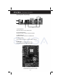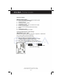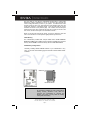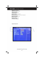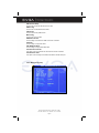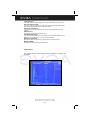
1
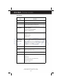
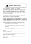
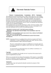
USER’S MANUAL
FOR
EVGA NFORCE 590 SLI
MOTHERBOARD
MODELS:
122-M2-NF59-AX
Notice:
Specifications and information contained in this documentation are
furnished for informational use only, and are subject to change at any
time without notice, and should not be construed as a commitment by the
manufacturer.
This manual covers the following motherboards from EVGA CORP.
122-M2-NF59-AX
CPU SUPPORT
The 122-M2-NF59-AX motherboard will support the following AMD AM2 CPUs:
•
•
•
•
Athlon 64 FX
Athlon 64 X2 (Dual Core)
Athlon 64
Sempron
122-M2-NF59 MANUAL - REV 1.0 - REV DATE 23 AUG 2006
EVGA Corporation 2900 Saturn St. Suite B, Brea, CA 92821
Phone: 888 / 881-EVGA - 714 / 528-4500 - Fax: 714 / 528-4501
Page 1
TABLE OF CONTENTS
Introduction to nForce 590 Motherboards
4
Motherboard Features
4
Special Features of the Motherboard
5
Specifications
6
Layout Diagram and Jumper Settings
7
Jumpers, Connectors, Headers, and Sockets
Hardware Installation
8
09
Hardware Installation Steps
09
Checking The Motherboard Jumper Settings
09
Clearing the CMOS RAM
09
Keyboard Power On Function
10
USB Power On Function
10
Installing The CPU
10
Glossary of Terms
10
About AMD Athlon64 AM2 CPUs
11
Installing Memory
12
Memory Installation Diagrams
13
Expansion Cards
14
Procedure For Expansion Card Installation
15
Assigning IRQs For Expansion Cards
15
Interrupt Request Table
15
PCI-Express Slots
15
Diagram of PCI-Express Slot Locations and Functions
16
Table of Standard IRQ Assignments
16
SLI Bridge Installation For NVIDIA SLI Cards (SLI Version Only)
17
Connectors and Headers
19
Connector Locations
19
Starting Up Your Computer
28
Beep Code Table
28
BIOS
29
Introducing BIOS
29
Entering BIOS Setup
29
Standard CMOS Features
30
Advanced BIOS Features
32
Advanced Chipset Features
33
System Clocks
34
System Voltages
35
System Monitor
41
Values and Descriptions
42
Nvidia Networking Guide
43
Configuring FirstPacket
44
Enabling FirstPacket
44
EVGA Corporation 2900 Saturn St. Suite B, Brea, CA 92821
Phone: 888 / 881-EVGA - 714 / 528-4500 - Fax: 714 / 528-4501
Page 2
TABLE OF CONTENTS (Continued)
Nvidia Networking Guide (continued)
Configuring TCP/IP Acceleration
45
Configuring Teaming
46
MediaShield RAID Manager
46
Create RAID Arrays
47
Nvidia nTune 5.0
53
Starting nTune
53
Adjust Motherboard Settings
54
Adjust GPU Settings
55
Dynamic BIOS Access
56
Tune System
56
View System Information
57
Nvidia Monitor
29
Driver Installation
59
RAID Installation
APPENDIX 1 - POST CODES
61
Quick Debug POST Codes
61
Boot Block POST Codes
62
APPENDIX 2 - TRADEMARKS AND NOTICES
64
Copyrights, Trademarks, and Notices
64
FCC Compliance Statement
64
APPENDIX 3 - CONTACTING SUPPORT AND OTHER USEFUL INFORMATION
EVGA Corporation 2900 Saturn St. Suite B, Brea, CA 92821
Phone: 888 / 881-EVGA - 714 / 528-4500 - Fax: 714 / 528-4501
Page 3
65
Introduction of nForce 590 Motherboards
Motherboard Features
Motherboards based on NVIDIA nForce 590 SLI x16 technology support the
innovative 64-bit AMD Athlon64 FX and dual core multi-tasking Athlon64 X2
processors with HyperTransport Technology. The SLI x16 version of the
motherboard series delivers leading-edge performance with both of the benefits
from 64-bit multi-tasking dual core AMD processors and NVIDIA Scalable Link
Interface (SLI) Technology with the latest Dual PCI-Express for NVIDIA Dual
Graphic Processing Unit ready platform. Utilizing the 64-bit multi-tasking socket
AM2 solution and dual channel DDR2 800, memory size expandable to 8.0GB,
this motherboard series meets the demands of computing in the future.
The NVIDIA nForce 590 SLI chipset offers ULTRA ATA 133 and Serial ATA
RAID 0, 1, 0+1 functions to accelerate hard disk drives and guarantee data
security without failure in advanced computing applications.
The motherboard provides dual Gigabit LAN by using two NVIDIA Giga-LAN
controllers both supporting 10M/100M/1Gbps data transfer rate and full duplex
or half duplex transportation. The embedded 8-channel AC’97 CODEC is fully
compatible with Sound Blaster ProTM standards and offers you home cinema
quality and complete software compatibility.
Two 16X PCI-Express graphics slots deliver up to 4Gbyte/sec data transfer rate
at each relative direction which is fully compatible with the latest NVIDIA SLI
Technology. And, two PCI-Express x1 slots offers expandability for future PCIE devices at 512Mbyte/sec concurrently, over 3.5 times more bandwidth than
PCI at 133Mbyte/sec, tackling the most demanding multimedia tasks.
The embedded USB controller has the capability to support up to 10 USB 2.0
ports, delivering 480Mb/s bandwidth each and the embedded Firewire
controller allows connection and use of IEE1394 compliant devices.
EVGA Corporation 2900 Saturn St. Suite B, Brea, CA 92821
Phone: 888 / 881-EVGA - 714 / 528-4500 - Fax: 714 / 528-4501
Page 4
Special Features of the Motherboard
CPU Thermal Throttling Technology
To prevent increasing heat from damaging the CPU or causing accidental
shutdown while under high workloads, the CPU Thermal Throttling Technology
will force the CPU to enter an idle mode from 87.5% to 12.5% according to
preset CPU operating temperatures in the BIOS (from 40○ to 90○). When the
system senses the CPU operating temperature reaching the preset value, the
CPU operating bandwidth will be decreased to the preset idle percentage
allowing the processor to cool down. When in throttling mode, a beeper sound
can be optionally selected to indicate it has reduced the CPU performance. (for
detailed settings, please read the BIOS PDF located on the CD)
Debug Port
The embedded Hardware Debug Port offers you a real-time visual system for
monitoring of your hardware. The embedded Debug Port will turn you into a
well trained hardware professional, allowing you to diagnose many hardware
issues. (For details please refer to Appendix A)
CPU Smart Fan
It’s never been a good idea to improve system performance by sacrificing
acoustics. The CPU Smart Fan Noise Management System is the answer to
control those noise levels. The system will automatically increase the fan speed
when the CPU operating load is high, and after the CPU returns to normal
operating condition, the system will slow the fan speed down to allow for a
silent operating environment.
EVGA Corporation 2900 Saturn St. Suite B, Brea, CA 92821
Phone: 888 / 881-EVGA - 714 / 528-4500 - Fax: 714 / 528-4501
Page 5
Specifications
Spec
Description
Design
ATX form factor 6 layers PCB size: 30.5 x 24.4cm
Chipset
NVIDIA nForce 590 SLI X16 Technology
CPU Socket AM2
Supports 64bit AMD Athlon64 Socket AM2 processors
Athlon 64 FX/ Athlon 64 X2/ Athlon 64/ and AM2 Sempron
Memory Sockets
Four 240-pin DIMM slots
Support Dual-Channel DDR2 533/667/800
Supports up to 8GB DDR2 memory
Expansion Slots
PCI-Express x16 slot x 2
PCI-Express x1 slot x 1
PCI-Express x4 slot x 1
32 bit PCI slots x 2
Integrated IDE and
One PCI IDE controller support PCI Bus Mastering, ATA PIO/DMA and the
Serial ATA RAID
ULTRA DMA 33/66/100/133 functions that deliver the data transfer rate up to
133 MB/s; Six Serial ATA ports provide 300 MB/sec data transfer rate for six
Serial ATA Devices and offer RAID 0, 1, 0+1 functions
LAN
Integrated dual 10Mb/100Mb/ 1Gb /s NVIDIA LAN’s
8CH-Audio
8-channel AC’97 Digital HD Audio controller integrated
SPDIF-In/ SPDIF-Out Optical support
BIOS
Multi I/O
Award 4MB Flash ROM
PS/2 keyboard and PS/2 mouse connectors
Serial port x1
USB2.0 port x 6
Audio connector (Line-in, Line-out, MIC/ 8CH Audio)
IEEE 1394a/b Firewire Support
S/PDIF Out 1x Optical
EVGA Corporation 2900 Saturn St. Suite B, Brea, CA 92821
Phone: 888 / 881-EVGA - 714 / 528-4500 - Fax: 714 / 528-4501
Page 6
Layout Diagram & Jumper Settings
5
1
2
4
3
1. PS/2 Mouse Port
This port is used to connect a PS/2 mouse
2. PS/2 Keyboard Port
This port is used to connect a PS/2 keyboard
3. IEEE1394b Port
This port is used to connect a 1394b device
4. USB 2.0 Ports
The six ports are used to connect USB 2.0 devices
5. LAN Ports
The left LED is no function (always off).
The right LED function sees below table
EVGA Corporation 2900 Saturn St. Suite B, Brea, CA 92821
Phone: 888 / 881-EVGA - 714 / 528-4500 - Fax: 714 / 528-4501
Page 7
JUMPERS, CONNECTORS, HEADERS, AND SOCKETS
EVGA Corporation 2900 Saturn St. Suite B, Brea, CA 92821
Phone: 888 / 881-EVGA - 714 / 528-4500 - Fax: 714 / 528-4501
Page 8
Hardware Installation
Hardware Installation Steps
Before using your computer, please complete the following steps:
1. Check motherboard jumper settings
2. Install CPU and Fan
3. Install System Memory (DIMM)
4. Install Expansion cards
5. Connect IDE and Floppy cables, Front /Back Panel cables
6. Connect ATX Power cable
7. Power-On and Load Standard Default BIOS Settings
8. Reboot
9. Install Operating System
10. Install Motherboard Drivers and Utilities
Checking the Motherboard’s Jumper Settings
CMOS RAM Clear (3-pin) : JBAT
A battery must be used to retain the motherboard configuration in CMOS RAM
short 1-2 pins of JBAT to store the CMOS data.
To clear the CMOS, follow the procedure below:
1. Turn off the system and unplug the AC power
2. Remove the ATX power cable from the ATX power connector
3. Locate JBAT and short pins 2-3 for a few seconds
4. Return JBAT to its normal setting by shorting pins 1-2
5. Connect the ATX power cable back to the ATX power connector
1
3
1
JBAT
3
JBAT
1-2 closed
Normal
2-3 closed
CMOS RAM Clear Setting
EVGA Corporation 2900 Saturn St. Suite B, Brea, CA 92821
Phone: 888 / 881-EVGA - 714 / 528-4500 - Fax: 714 / 528-4501
Page 9
Clear CMOS
Install CPU
Glossary
Chipset (or core logic) - one or more integrated circuits which control the
interfaces between the system processor, RAM, I/O devises, and adapter
cards.
Processor slot/socket - the slot or socket used to mount the system processor
on the motherboard.
Slot (PCI-E, PCI, RAM) - the slots used to mount adapter cards and system
RAM.
PCI - Peripheral Component Interconnect - a high speed interface for video
cards, sound cards, network interface cards, and modems; runs at 33MHz.
PCI-Express- Peripheral Component Interconnect Express- a high speed
interface for video cards, sound cards, network interface cards, and modems.
Serial Port - a low speed interface typically used for mouse and external
modems.
Parallel Port - a low speed interface typically used for printers.
PS/2 - a low speed interface used for mouse and keyboards.
USB - Universal Serial Bus - a medium speed interface typically used for
mouse, keyboards, scanners, and some digital cameras.
Sound (interface) - the interface between the sound card or integrated sound
connectors and speakers, MIC, game controllers, and MIDI sound devices.
LAN (interface) - Local Area Network - the interface to your local area network.
BIOS (Basic Input/Output System) - the program logic used to boot up a
computer and establish the relationship between the various components.
Driver - software, which defines the characteristics of a device for use
by another device or other software.
Processor - the "central processing unit" (CPU); the principal integrated circuit
used for doing the "computing" in "personal computer"
Front Side Bus Frequency - the working frequency of the motherboard, which
is generated by the clock generator for CPU, DRAM and PCI BUS.
CPU L2 Cache - the flash memory inside the CPU, normal it depend on CPU
type.
About AMD Athlon64 AM2 CPUs
This motherboard provides an AM2 socket surface mount, Zero Insertion Force
(ZIF) socket, referred to as the mPGA940 socket supporting AMD Athlon64
processors in the AM2 package utilizing Flip-Chip Pin Grid Array technology.
EVGA Corporation 2900 Saturn St. Suite B, Brea, CA 92821
Phone: 888 / 881-EVGA - 714 / 528-4500 - Fax: 714 / 528-4501
Page 10
The CPU that you use with the motherboard should have a cooling FAN
attached to prevent overheating. If this is not the case, then purchase the
correct cooling FAN before you turn on your system. To install a CPU, locate
the ZIF socket and open it by first pulling the lever sideways away from the
socket then upward to a 90-degree angle. Insert the CPU with the correct
orientation as shown on the previous page. The notched corner should point
toward the end of the lever. Because the CPU has a corner pin for two of the
four corners, the CPU will only fit in the orientation as shown.
When you put the CPU into the ZIF socket. No force is required to insert the
CPU. Press the lever to Locate position slightly without any extra force.
Install Memory
This motherboard provides four 240-pin DDR2 DUAL INLINE MEMORY
MODULES (DIMM) slots for DDR2 memory expansion available from minimum
memory size of 256MB to maximum memory size of 8.0GB DDR SDRAM.
Valid Memory Configurations
Generally, installing DDR2 SDRAM modules to your motherboard is very
easy, you can refer to the following page to see what a 240-Pin DDR2 module
looks like.
S ock et A M 2
Golden Arrow
CPU ZIF mPGAB Socket
WARNING!
Be sure that there is sufficient air circulation across
the processor’s heatsink and CPU cooling FAN is
working correctly, otherwise it may cause the
processor and motherboard to overheat and
damage your system, you may install an auxiliary
cooling FAN, if necessary.
EVGA Corporation 2900 Saturn St. Suite B, Brea, CA 92821
Phone: 888 / 881-EVGA - 714 / 528-4500 - Fax: 714 / 528-4501
Page 11
Bank
184-Pin DIMM
PCS
Total Memory
Bank 0, 1 (DIMM1)
DDR2 533/667/800
DDR2 SDRAM Module
X1
256MB~2.0GB
Bank 2, 3 (DIMM2)
DDR2 533/667/800
DDR2 SDRAM Module
X1
256MB~2.0GB
Bank 4, 5 (DIMM3)
DDR2 533/667/800
DDR2 SDRAM Module
X1
256MB~2.0GB
Bank 6,7 (DIMM4)
DDR2 533/667/800
DDR2 SDRAM Module
X1
256MB~2.0GB
System Memory (Max. 8.0GB)
4
256MB~2.0GB
Total
For Dual Channel Memory
Dual channel only operates when 2 DIMM Modules are plugged into either
DIMM1 & DIMM3 or DIMM2 & DIMM4, or four DIMM Modules are
plugged into DIMM1~DIMM4.
DIMM1 & DIMM3, or DIMM2 & DIMM4 must be the same type, same size, and
same frequency for dual channel to function.
Note: Place Memory DIMM’s into matching color slots for Dual Channel.
Computer will not boot if RAM is in 3 and 4 only.
EVGA Corporation 2900 Saturn St. Suite B, Brea, CA 92821
Phone: 888 / 881-EVGA - 714 / 528-4500 - Fax: 714 / 528-4501
Page 12
Expansion Cards
WARNING!
Turn off your system power when adding or removing
expansion cards or other system components. Failure
to do so may cause severe damage to both your
motherboard and expansion cards.
Procedure For Expansion Card Installation
Read the documentation for your expansion card and make any necessary
hardware or software setting for your expansion card such as jumpers.
Remove your computer’s cover and the bracket plate on the slot you intend to
use.
•
•
•
•
•
Align the card’s connectors and press firmly.
Secure the card on the slot with the screen you remove above.
Replace the computer system’s cover.
Set up the BIOS if necessary.
Install the necessary software driver for your expansion card.
Assigning IRQs For Expansion Card
Some expansion cards need an IRQ to operate. Generally, an IRQ must be
exclusively assigned. In a standard design, there are 16 IRQs available but
most of them are already in use. The following table will show you the default
assignment of IRQs.
If should be noted that in most modern Plug and Play Operating Systems, that
IRQ assignment is handled by the computer itself automatically. This automatic
assignment is generally very effective and you should only have to resort to
manual assignment in the most extreme cases.
EVGA Corporation 2900 Saturn St. Suite B, Brea, CA 92821
Phone: 888 / 881-EVGA - 714 / 528-4500 - Fax: 714 / 528-4501
Page 13
Interrupt Request Table For This Motherboard
Interrupt requests are shared as shown in the table below:
INT A
Slot 1
INT B
INT C
AC97/MC97
IMPORTANT!
INT F
INT G
INT H
X
Slot 3
Onboard USB 2
INT E
X
Slot 2
Onboard USB 1
INT D
X
X
X
X
If using PCI cards on shared slots, make sure that
the drivers support “Shared IRQ” or that the cards
don’t need IRQ assignments. Conflicts will arise
between the two PCI groups that will make the
system unstable or cards inoperable.
PCI-Express Slots
This motherboard provides two PCI-Express slots intended for Graphics (Two
symmetrical PCI-Express x16 graphics slots deliver up to 4Gbyte/sec data
transfer rate at each relative direction which is fully compatible with the latest
NVIDIA SLI Technology [SLI version only]. There is also a x1 PCI-Express slot
and a x4 PCI-Express slot. Fully compliant to the PCI-Express Base Specification revision 1.0a , supporting PCI-Express VGA cards, and other PCI-Express
devices.
FROM TOP TO BOTTOM
16x PCI-E
1x PCI-E
4x PCI-E
16x PCI-E
EVGA Corporation 2900 Saturn St. Suite B, Brea, CA 92821
Phone: 888 / 881-EVGA - 714 / 528-4500 - Fax: 714 / 528-4501
Page 14
Standard Interrupt Assignments
IRQ
Priority
0
N/A
Standard function
System Timer
1
N/A
Keyboard Controller
2
N/A
Programmable Interrupt
3*
8
Communications Port (COM2)
4*
9
Communications Port (COM1)
5*
6
Sound Card (sometimes LPT2)
6*
11
Floppy Disk Controller
7*
7
8
N/A
Printer Port (LPT1)
System CMOS/Real Time Clock
9*
10
ACPI Mode when enabled
10 *
3
IRQ Holder for PCI Steering
11 *
2
IRQ Holder for PCI Steering
12 *
4
PS/2 Compatible Mouse Port
13
N/A
14 *
5
Numeric Data Processor
Primary IDE Channel
15 *
1
Secondary IDE Channel
* These IRQs are usually available for PCI devices.
EVGA Corporation 2900 Saturn St. Suite B, Brea, CA 92821
Phone: 888 / 881-EVGA - 714 / 528-4500 - Fax: 714 / 528-4501
Page 15
SLI Bridge for NVIDIA SLI Supported VGA Cards
In order to activate the NVIDIA SLI technology (SLI version only), you have to
install the included SLI Bridge for your NVIDIA SLI Supported VGA Cards
before you can activate the advanced multi-GPU functions.
STEP 1 - Install your NVIDIA SLI Supported VGA Cards in the PCI-E x8 slots
located on the left and right, leaving the center PCI-E slot vacant.
STEP 2 - Prepare to install the SLI Bridge with your NVIDIA SLI Supported
VGA Cards
EVGA Corporation 2900 Saturn St. Suite B, Brea, CA 92821
Phone: 888 / 881-EVGA - 714 / 528-4500 - Fax: 714 / 528-4501
Page 16
STEP 3 - Be careful with the pins as to not damage the adapter or graphics
cards during installation.
STEP 4 - Plug the SLI Bridge adapter onto both of the NVIDIA SLI Supported
VGA Cards
EVGA Corporation 2900 Saturn St. Suite B, Brea, CA 92821
Phone: 888 / 881-EVGA - 714 / 528-4500 - Fax: 714 / 528-4501
Page 17
Connectors and Headers
Connectors
Power Connector (24-pin block) : ATXPWR
ATX Power Supply connector. This is a newly defined 24-pin connector that
usually comes with an ATX case. The ATX Power Supply allows you to use soft
power on momentary switch that connects from the front panel switch to 2-pins
Power On jumper pole on the motherboard. When the power switch on the
back of the ATX power supply is turned on, the full power will not come into the
system board until the front panel switch is momentarily pressed. Press this
switch again to turn off the power to the system board.
We recommend that you use an ATX 12V Specification 2.0-compliant power
supply unit (PSU) with a minimum of 350W power rating. This type has both 24pin and the 4-pin power plugs needed.
If you intend to use a PSU with 20-pin and 4-pin power plugs, make sure that
the 20-pin power plug can provide at least 15A on +12V and the power supply
unit has a minimum power rating of 350W. The system may become unstable
or may not boot up if the power is inadequate.
PIN
1
2
3
4
5
6
7
8
9
10
11
12
ROW1
3.3V
3.3V
GND
5V
GND
5V
GND
Power OK
+5V (for Soft Logic)
+12V
+12V
+3V
EVGA Corporation 2900 Saturn St. Suite B, Brea, CA 92821
Phone: 888 / 881-EVGA - 714 / 528-4500 - Fax: 714 / 528-4501
Page 18
ROW2
3.3V
-12V
GND
Soft Power On
GND
GND
GND
-5V
+5V
+5V
+5V
GND
ATX 12V Power Connector (8-pin block) : ATX12V
This is a newly defined 8-pin connector that usually comes with the ATX Power
Supply. The ATX Power Supply which fully supports the extra 12V voltage to
maintain system power consumption. Without this connector the system will
become unstable because the power supply can not provide sufficient current
for all the system components
PS/2 Mouse & PS/2 Keyboard Connector: KB
The connectors for PS/2 keyboard and PS/2 Mouse.
LAN Port connector: UL1
This connector is standard RJ45 connector for Ethernet connections.
EVGA Corporation 2900 Saturn St. Suite B, Brea, CA 92821
Phone: 888 / 881-EVGA - 714 / 528-4500 - Fax: 714 / 528-4501
Page 19
LAN Port connector: UL2
This connector is standard RJ45 connector for Ethernet connections.
Audio Line-In, Lin-Out, MIC, Surrback, Surround, CEN/LEF Connector : J1
This Connector has 6 audio jacks for LINE-OUT, LINE-IN, MIC, Surrback, Surround, CEN/LEF
Line-in (BLUE)
Line-out (GREEN)
MIC (PINK)
Surrback (ORANGE)
CEN/LEF (BLACKNESS)
Surround (GRAY)
Audio input to sound chip
Audio output to speaker
Microphone Connector
Rear speaker out
Center/Subwoofer speaker out
Side speaker out
EVGA Corporation 2900 Saturn St. Suite B, Brea, CA 92821
Phone: 888 / 881-EVGA - 714 / 528-4500 - Fax: 714 / 528-4501
Page 20
Floppy drive Connector (34-pin block): FDD
This connector supports the provided floppy drive ribbon cable. After connecting
the single plug end to motherboard, connect the two plugs at other end to the
floppy drives.
FDD
Pin 1
Floppy Drive Connector
Primary IDE Connector (40-pin block): IDE1
This connector supports the provided IDE hard disk ribbon cable. After connecting the single plug end to motherboard, connect the two plugs at the other end
to your hard disk(s). If you install two hard disks, you must configure the second
drive to Slave mode by setting its jumpers accordingly. Please refer to the
documentation of your hard disk for the jumper settings.
IDE1
Pin 1
Primary IDE Connector
EVGA Corporation 2900 Saturn St. Suite B, Brea, CA 92821
Phone: 888 / 881-EVGA - 714 / 528-4500 - Fax: 714 / 528-4501
Page 21
Two hard disks can be connected to each connector. The first HDD is referred
to as the “Master” and the second HDD is referred to as the “Slave”.
For best performance, we strongly suggest you don’t install a CD-ROM or DVDROM drive on the same IDE channel as a hard disk. Otherwise, the system
performance on this channel will not be able to achieve its maximum ATA133
speed.
Serial-ATA Port: SATA1 / SATA2 / SATA3/ SATA4/ SATA5 /SATA 6
This connector support the provided Serial ATA IDE hard disk cable to
connecting the motherboard and serial ATA hard disk. The motherboard will
support both SATA 150 and 300 standards.
1
2
3
4
Serial-ATA Port Connectors
6
5
Serial-ATA Port Connectors
EVGA Corporation 2900 Saturn St. Suite B, Brea, CA 92821
Phone: 888 / 881-EVGA - 714 / 528-4500 - Fax: 714 / 528-4501
Page 22
Headers
Line-Out/MIC Header for Front Panel (9-pin): AUDIO
AUDIO
AUD_RET_L
AUD_GND
AUD_VCC
AUD_RET_R
This header connects to Front Panel Line-out, MIC connector with cable.
Without installing this cable, this header default setting is 5-6 short, 9-10 short.
When you install the cable you have take off these jumpers.
2
10
Pin 1
AUD_MIC
AUD_MIC_BIAS
AUD_FPOUT_R
HP_ON
AUD_FPOUT_L
9
Line-Out, MIC Headers
USB Port Headers (9-pin) : USB1/USB2/USB3
VCC
-DATA
+DATA
GND
OC
VCC
-DATA
+DATA
GND
-DATA
+DATA
GND
OC
-DATA
+DATA
GND
VCC
VCC
USB3
Pin 1
Pin 1
-DATA
+DATA
GND
Pin 1
USB2
VCC
VCC
USB1
-DATA
+DATA
GND
OC
These headers are used for connecting the additional USB port plug. By
attaching an optional USB cable, your can be provided with two additional USB
plugs affixed to the back panel.
USB Port Headers
EVGA Corporation 2900 Saturn St. Suite B, Brea, CA 92821
Phone: 888 / 881-EVGA - 714 / 528-4500 - Fax: 714 / 528-4501
Page 23
Speaker connector: SPEAK
This 4-pin connector connects to the case-mounted speaker. See the figure
below.
Power LED: PWR LED
The Power LED is light on while the system power is on. Connect the Power
LED from the system case to this pin.
IDE Activity LED: HD LED
This connector connects to the hard disk activity indicator light on the case.
Reset switch lead: RESET
This 2-pin connector connects to the case-mounted reset switch for rebooting
your computer without having to turn off your power switch. This is a preferred
method of rebooting in order to prolong the lift of the system’s power supply.
See the figure below.
Power switch: PWR BTN
JW FP
PWRBTN
GND
PWRBTN
PWRLED
Pin 1
PWRLED
VCC5
PWR LED
This 2-pin connector connects to the case-mounted power switch to power ON/
OFF the system.
SPEAK
VCC5
HDDLE
GND
RSTSW
NC
HDLED
RESET
GND
VCC5
Pin 1
SPKR
NC
Pin 1
System Case Connections
EVGA Corporation 2900 Saturn St. Suite B, Brea, CA 92821
Phone: 888 / 881-EVGA - 714 / 528-4500 - Fax: 714 / 528-4501
Page 24
FAN Headers (3-pin) : CPUFAN, SYSFAN1
These connectors support cooling fans of 350mA (4.2 Watts) or less,
depending on the fan manufacturer, the wire and plug may be different. The
red wire should be positive, while the black should be ground. Connect the
fan’s plug to the board taking into consideration the polarity of connector.
CD Audio-In Headers (4-pin) : CDIN
CDIN are the connectors for CD-Audio Input signal. Please connect it to CDROM CD-Audio output connector.
EVGA Corporation 2900 Saturn St. Suite B, Brea, CA 92821
Phone: 888 / 881-EVGA - 714 / 528-4500 - Fax: 714 / 528-4501
Page 25
Firewire Connectors : 1394A~B
These connectors support the connection of firewire (IEEE1394) devices.
Supplemental SLI Power: J2
This 4-pin Molex type power connector is only required when running the
system in an SLI configuration( SLI EZ-Plug). This allows additional power to
be channeled to the video cards in order to better maintain stability.
EVGA Corporation 2900 Saturn St. Suite B, Brea, CA 92821
Phone: 888 / 881-EVGA - 714 / 528-4500 - Fax: 714 / 528-4501
Page 26
Starting Up Your Computer
After all connections are made, close your computer case cover.
Be sure all the switches are off, and check that the power supply input voltage
is set to proper position, usually input voltage is 110V~120V or 220V~240V
depending on your country’s voltage used. In the United States, this is
110V~120V - typically the switch on a computer power supply will be marked
with 115V to indicate this setting.
Connect the power supply cord into the power supply located on the back of
your system case according to your system user’s manual.
Turn on your peripherals in the following order:
•
Your monitor.
•
Other external peripheral (Printer, Scanner, External Modem etc…)
•
Your system power. For ATX power supplies, you need to turn on the
power supply and press the ATX power switch on the front side of the
case.
The power LED on the front panel of the system case will light up. The LED on
the monitor may light up or switch between orange and green after the system
is on. If it complies with green standards or if it is has a power standby feature.
The system will then run power-on test.
If you do not see any thing within 30 seconds from the time you turn on the
power. The system may have failed on power-on test. Recheck your jumper
settings and connections or call your retailer for assistance.
If there are any errors during start up, your computer will issue a series of beep
codes in addition to displaying the last BIOS operation on the POST code
diagnostic LED. A list of common beep codes follows:
Beep
Meaning
One short beep when displaying logo
No error during POST
Long beeps in an endless loop
No DRAM install or detected
One long beep followed by three short beeps
Video card not found or video card memory bad
High frequency beeps when system is working
CPU overheated
System running at a lower frequency
During power-on, press <Delete> key to enter BIOS setup. Follow the
instructions in the BIOS PDF located in the Manuals Section of the Installation
CD.
EVGA Corporation 2900 Saturn St. Suite B, Brea, CA 92821
Phone: 888 / 881-EVGA - 714 / 528-4500 - Fax: 714 / 528-4501
Page 27
BIOS Description
Enter BIOS Setup
The BIOS is the communication bridge between the hardware and software,
correctly setting up the BIOS parameters is critical to maintain optimal system
performance. Power on the computer, when the following message briefly
appears at the bottom of the screen during the POST (Power On Self Test),
press <Del> key to enter the Award BIOS CMOS Setup Utility.
Press F1 to continue, DEL to enter Setup.
Note: It is recommended that the default settings in the BIOS are not changed.
The user accepts all responsibility for any damage that results from changing
the default settings.
Main Menu
The main menu allows you to select from the list of setup functions and two exit
choices. User the arrow keys to select among the items and press <ENTER> to
accept or go to the sub-menu.
The items in the main menu are:
Standard CMOS Features
The basic system configuration can be setup through this menu.
Advanced BIOS Features
The advanced system features and boot sequence can be setup through this menu.
Advanced Chipset Features
Optimize system performance through this menu. Configure clocks, voltages, memory
timings, and more.
Integrated Peripherals
Onboard peripherals such as RAID, USB, and MAC control can be setup through this
menu.
Power Management Setup
Configure power management, power-on, and sleep features through this menu.
PnP/PCI Configurations
The system’s Plug-and-Play and PCI configurations can be modified through this menu.
System Monitor
Monitor the real-time system status of your PC, including temperature, voltage, and fan
speed.
EVGA Corporation 2900 Saturn St. Suite B, Brea, CA 92821
Phone: 888 / 881-EVGA - 714 / 528-4500 - Fax: 714 / 528-4501
Page 28
Load Defaults
Load the NVIDIA LinkBoost™ Technology settings for LinkBoost™ enabled systems. Load
default system settings for standard systems.
Set Password
Set the password to access the BIOS menu.
Set User Name
Set the BIOS Welcome screen name.
Save & Exit Setup
Save settings and exit setup.
Exit Without Saving
Abandon all setting changes and exit setup.
Standard CMOS Features
This sub-menu is used to setup the standard CMOS features, such as the date,
time, and HDD model. Use the arrow keys to select the item to setup, and then
use the <PgUp> or <PgDn> keys to choose the setting values.
Date
This option allows you to set the desired date with the <month><date><year> format.
Time
This option allows you to setup the desired time with <hour><minute><second> format.
EVGA Corporation 2900 Saturn St. Suite B, Brea, CA 92821
Phone: 888 / 881-EVGA - 714 / 528-4500 - Fax: 714 / 528-4501
Page 29
•“None” means no HDD is installed or set.
•“Auto” means the system can auto-detect the hard disk when booting up
•“Manual” mean the information can be entered manually. Note: “Access Mode”
must also be set to “CHS” to enable manual entry.
Cylinder Number of cylinders
Head
Number of heads
Precomp Write pre-compensation
Landing Zone
Landing zone
Sector
Number of sectors
Award (Phoenix) BIOS can support 3 HDD modules: CHS, LBA, and Large or
Auto mode.
CHS
For HDD < 528 MB
LBA
For HDD > 528 MB & supporting LBA (Logical Block Addressing)
Large
For HDD > 528 MB but not supporting LBA
Auto
Recommended mode
Floppy Drive A
This option allows you to select the kind of FDD to be installed, including
“None”.
Halt On
This category determines whether or not the computer will stop if an error is
detected during powering up.
All Errors Whenever the BIOS detects a nonfatal error, the system will stop and
you will be prompted.
No Errors The system boot will not stop for any errors that may be detected.
All, But Keyboard The system boot will not stop for a keyboard error; but it
will stop for all other errors.
All, But Diskette
The system boot will not stop for a diskette error; but it will
stop for all other errors.
All, But Disk/Key
The system boot will not stop for a keyboard or disk error,
but it will stop for all other errors.
Memory
This is a Display-Only category determined by POST (Power On Self Test) of
the BIOS.
Base Memory
The BIOS POST will determine the amount of base (or conventional) memory
installed in the system.
Extended Memory
The BIOS determines how much extended memory is present during the
POST.
Total Memory
Total memory of the system.
EVGA Corporation 2900 Saturn St. Suite B, Brea, CA 92821
Phone: 888 / 881-EVGA - 714 / 528-4500 - Fax: 714 / 528-4501
Page 30
Advanced BIOS Features
Removable Device Priority
This option is used to select the priority for Removable device startup. After pressing
<Enter>, you can select the removable device using the <PageUp>/<PageDn> are arrow
keys, and change the removable device priority using <+> or <->.
Hard Disk Boot Priority
This option is used to select the priority for HDD startup. After pressing <Enter>, you can
select the HDD using the <PageUp>/<PageDn> are arrow keys, and change the HDD
priority using <+> or <->.
Network Boot Priority
This option is used to select the priority for Network startup. After pressing <Enter>, you
can select the Network using the <PageUp>/<PageDn> are arrow keys, and change the
Network priority using <+> or <->.
CPU Internal Cache
This option enables or disables the CPU internal caches.
Quick Power On Self Test
Enable to reduce the time for power on self test
First/Second/Third Boot Device
This option allows you to set the boot device’s sequence.
Boot Other Device
With this function set to enable, the system will boot from some other devices if the first/
second/thrist boot devices failed.
Boot Up NumLock Status
This item defines if the keyboard Num Lock key is active when your system is started.
Security Option
When it is set to “Setup”, a password is required to enter the CMOS Setup screen; When it
is set to “System”, a password is required not only to enter CMOS setup, but also to
start up your PC.
APIC Mode
This option is used to enabled or disable APIC function.
MPS Version Control for OS
This option is used to setup the version of MPS Table used in NT4.0 OS.
Full Screen Logo Show
This option allows you to enabled or disable to full-screen logo.
EVGA Corporation 2900 Saturn St. Suite B, Brea, CA 92821
Phone: 888 / 881-EVGA - 714 / 528-4500 - Fax: 714 / 528-4501
Page 31
Advanced Chipset Features
Use this section to control chipset features, specifically clocks, voltages, and
memory timings.
System Clocks
Use this menu to control system clocks (see System Clocks section below)
System Voltages
Use this menu to control system voltages (see System Voltages section below)
Memory Configuration
Use this menu to control memory settings (see Memory Configuration section below)
PCI Clocks
Use this menu to turn off the PCI clock on the unused PCI slot
LPC P2P P2P
Decoding mode for LPC and P2P
SSE/SSE2 Instructions
Enable/Disable Stream SIMD Extensions
System BIOS Cacheable
Enable the memory cache function for BIOS
Load timing/voltage settings
Load timing and voltage settings from a profile
Save timing/voltage settings
Save timing and voltage settings to a profile
EVGA Corporation 2900 Saturn St. Suite B, Brea, CA 92821
Phone: 888 / 881-EVGA - 714 / 528-4500 - Fax: 714 / 528-4501
Page 32
System Clocks
Use this section to control chipset features, specifically clocks, voltages, and
memory timings.
Frequency Settings
Ref Clock (HTT)
Reference clock frequency
CPU Multiplier
The value of the CPU multiplier
PCIe Bus, Slot 1
The frequency of the PCI-Express Bus, Slot 1
PCIe Bus, Slot 2
The frequency of the PCI-Express Bus, Slot 2
SPP <> MCP Ref Clock
The frequency of the reference clock between SPP and MCP chips
HT Multiplier
CPU <> nForce SPP
The HT multiplier between the CPU and the SPP
nForce SPP > nForce MCP
The HT multiplier from the SPP to the MCP
HT Width
CPU < > nForce SPP
The HT width between the CPU and the SPP
nForce SPP <> nForce MCP
The HT width between the SPP and the MCP
EVGA Corporation 2900 Saturn St. Suite B, Brea, CA 92821
Phone: 888 / 881-EVGA - 714 / 528-4500 - Fax: 714 / 528-4501
Page 33
System Voltages
CPU
Voltage to the CPU
Memory
Voltage to the DRAM
HT CPU <> nForce SPP
Voltage of the HT link between the CPU and the SPP
HT nForce SPP <> MCP
Voltage of the HT link between the SPP and the MCP
nForce SPP
Voltage of the nForce SPP
nForce MCP
Voltage of the nForce MCP
Auxiliary
Voltage of the SPP auxiliary
Memory Configuration
EVGA Corporation 2900 Saturn St. Suite B, Brea, CA 92821
Phone: 888 / 881-EVGA - 714 / 528-4500 - Fax: 714 / 528-4501
Page 34
Memory Configuration
Optimized for nForce Mem
Enable memory settings that are Optimized for nForce (only functional with DRAM that is
Optimzed for nForce).
Memory Timings
Use this menu to control memory timings (see Memory Timings section below)
Drive Strength setting
Use this menu to control drive strength settings (see Drive Strength settings section below)
Dram on-die termination
Resistance of the on-die termination resistors
Read/Write queue bypass
Number of times to bypass the read/write queue
Bypass Maximum
Max number of times that the oldest memory access request can be bypassed
32 Byte Granularity
32/64 byte DRAM access granularity
NVMEM memory test
Run NVIDIA memory testing module during POST
DQS Training Control
Perform/Skip DQS training
CKE base power down mode
Enable/Disable CKE base power down mode
CKE power down control
CKE power down mode selection. It should be set to “per channel” for non mobile systems.
Memclock tri-stating
Memclock tri-stating during C3 and Alt VID
Memory Hole remapping
Enable/Disable memory hole remapping
Auto Optimize Bottom IO
Auto optimize maximum DRAM size when kernel assigns PCI resources done.
Memory Timings
EVGA Corporation 2900 Saturn St. Suite B, Brea, CA 92821
Phone: 888 / 881-EVGA - 714 / 528-4500 - Fax: 714 / 528-4501
Page 35
Memory Timings
Standard Memory Settings
Timing mode
Select automatic or manual set memory timing
tCL (CAS Latency)
CAS Latency (CAS# to read data valid)
tRCD
RAS# to CAS# delay for a RD/WR command to the same bank
tRP
Row Precharge time Precharge-to-Active or Auto-Refresh of the same bank
tRAS
Minimum RAS# active time
Command Per Clock (CMD)
Command timing setting (per clock unit)
Advance Memory Settings
tRRD
RAS# to RAS# delay of different banks
AsyncLat
Max round trip latency from the CPU to the DRAM
tRC
RAS# to RAS# or auto refresh time of the same bank
tWR
Write recovery time
tRWT
Minimum read to write turnaround time
tWTR
Minimum write to read delay with same chip select
tREF
DRAM refresh rate
Read DQS Skew
Read DQS delayed with respect to the data. 1/96 MEMCLK per unit.
Read delay from Rx FIFO
Delay from DQS receiver enable to first data read from Rx FIFO.
Drive Strength Setting
EVGA Corporation 2900 Saturn St. Suite B, Brea, CA 92821
Phone: 888 / 881-EVGA - 714 / 528-4500 - Fax: 714 / 528-4501
Page 36
DRAM driver weak mode
DRAM data drive strength on DRAM
CKE drive strength
Drive strength of the CKE pins
CS drive strength
Drive strength of the CS and ODT pins
MA drive strength
Drive strength of the Address, RAS, CAS, WE, and parity pins
MCLK drive strength
Drive strength of the MEMCLK pins
MD drive strength
Drive strength of the Data pins
DQS drive strength
Drive strength of the DQS pins
Integrated Peripherals
EVGA Corporation 2900 Saturn St. Suite B, Brea, CA 92821
Phone: 888 / 881-EVGA - 714 / 528-4500 - Fax: 714 / 528-4501
Page 37
IDE Function Setup
Use this menu to setup the data flow control for IDE
RAID Config
Use this menu to enable/disable SATA RAID
USB Config
Use this menu to setup USB interface
MAC Config
Use this menu to turn off MAC
IEEE1394 controller
Use this setting to set whether the IEEE 1394 function is enabled.
HD Audio
Use this setting to configure HD Audio
IDE HDD Block Mode
Use this setting to configure HDD Block Mode
Onboard FDC Controller
This option is used to set whether the Onboard FDC Controller is enabled.
Onboard Serial Port 1
This option is used to assign the I/O address and IRQ for onboard serial port 1.
Power Management Setup
EVGA Corporation 2900 Saturn St. Suite B, Brea, CA 92821
Phone: 888 / 881-EVGA - 714 / 528-4500 - Fax: 714 / 528-4501
Page 38
ACPI Suspend Type
This option is used to set the energy saving mode of the ACPI function. When you select
“S1 (POS)” mode, the power will not shut off and the supply status will remain as it is. In S1
mode the computer can be resumed at any time. When you select “S3(STR)” mode, the
power will be cut off after a delay period. The status of the computer before it enters STR
will be saved in memory, and the computer can quickly return to the previous state when
the STR function wakes. When you select “S1 & S3” mode, the system will automatically
select the delay time.
C States Support
CPU power state selection
Soft-Off by PBTN
This option is used to set the power down method. This function is only valid for system
using an ATX power supply.
When “Instant-Off” is selected, press the power switch to immediately turn off power.
When “Delay 4 Sec” is selected, press and hold the power button for four seconds to turn
off power.
WOL(PME#) From Soft-Off
This item is used to set the system to wake-up on LAN.
WOR(RI#) From Soft-Off
This item is used to set the system to wake-up on ring.
AMD Cool’n’Quiet
Use this option to enable or disable AMD Cool’n’Quiet™ Technology.
Power-on by Alarm
This item is used to set the timing of the power-on function.
POWER ON Function
This option is used to set the power on method for your PC.
PnP/PCI Configurations
EVGA Corporation 2900 Saturn St. Suite B, Brea, CA 92821
Phone: 888 / 881-EVGA - 714 / 528-4500 - Fax: 714 / 528-4501
Page 39
Init Display First
This option is used to set which display device will be used first when your PC starts up.
Reset Configuration Data
This option is used to set whether the system is permitted to automatically distribute IRQ,
DMA, and I/O addresses each time the machine is turned on.
Resources Controlled by
Use this option to determine if IRQ resources are automatically assigned or manually
assigned
IRQ Resources
Press <Enter> to manually assign IRQ resources.
PCI/VGA Pallette Snoop
If you use a non-standard VGA card, use this option to solve graphic acceleration card or
MPEG audio card problems (e.g. colors not accurately displayed).
Maximum Payload Size
This option is ued to set maximum TLP payload size for PCI Express devices.
Maximum ASPM
Enable/Disable Advance State Power Management
System Monitor
The “System Monitor” screen displays real-time temperatures, voltages, and
fan speeds.
EVGA Corporation 2900 Saturn St. Suite B, Brea, CA 92821
Phone: 888 / 881-EVGA - 714 / 528-4500 - Fax: 714 / 528-4501
Page 40
Temperature Values
This option is used to set which display device will be used first when your PC starts up.
System
The temperature of the system
CPU
The temperature of the CPU
Board
The temperature of the motherboard
Voltage values
CPU
The voltage of the CPU
Memory
The voltage of the Memory
+3.3V
The voltage of the +3.3V
+3.3V Dual
The voltage of the +3.3V Dual
+5V
The voltage of the +5V
nForce MCP
The voltage of the nForce MCP chip
nForce SPP
The voltage of the nForce SPP chip
HT CPU <-> nForce SPP
The voltage of the HT between the CPU and the nForce SPP chip
+Vbat
The voltage of +Vbat
Fan Speed values
CPU Fan Speed
The CPU fan speed
MCP Fan Speed
The MCP fan speed
Sys Fan Speed
The system fan speed
Load Defaults
The BIOS defaults sets the basic system functions that ensure system stability. If the
system is NVIDIA LinkBoost™ enabled, the default settings are the LinkBoost settings.
If your computer cannot POST properly, you should load the Defaults to restore the original
settings.
Set Password
The password can be used to start the system or modify the CMOS settings. When you
select the Set Password option, the following message will appear in the center of the
screen:
Enter Password:
Enter your password, not exceeding 8 characters, then press <Enter>. The password you
enter will replace any previous password. When prompted, key in the new password and
press <Enter>. If you do not want to set a password, just press <Enter> when prompted to
enter a password, and in the screen the following message will appear. If no password is
keyed in, any user can enter the system and view/modify the CMOS settings.
Password Disabled!!!
Press any key to continue…
EVGA Corporation 2900 Saturn St. Suite B, Brea, CA 92821
Phone: 888 / 881-EVGA - 714 / 528-4500 - Fax: 714 / 528-4501
Page 41
Save & Exit Setup
When you select this option and press <Enter>, the following message will
appear in the center of the screen:
SAVE to CMOS and EXIT (Y/N)?
Press <Y> to save your changes in CMOS and exit the program; press <N> or
<ESC> to return to the main menu.
Exit Without Saving
If you select this option and press <Enter>, the following message will appear in
the center of the screen:
Quit Without Saving (Y/N)?
Press <Y> to exit CMOS without saving your modifications; press <N> or
<ESC> to return to the main menu
NVIDIA Networking Guide
Launching NVIDIA Networking
Click on Start > All Programs > NVIDIA Corporation > NVIDIA Control Panel.
The following GUI appears:
Figure 1 Networking Control Panel Intro Page
Click on Networking; the following GUI appears:
EVGA Corporation 2900 Saturn St. Suite B, Brea, CA 92821
Phone: 888 / 881-EVGA - 714 / 528-4500 - Fax: 714 / 528-4501
Page 42
Configuring FirstPacket:
Click on “Enable FirstPacket (recommended)” to enable FirstPacket.
The following screen appears
Figure 4 Enabling FirstPacket
Select the appropriate speed for your network.
To define a custom speed do the following:
Click on “Custom speed”.
Enter the exact speed of your network.
Click on “Apply”.
In order to select which application is to be accelerated, do the following:
Click on “Program Prioritized by FirstPacket”; the following screen appears
EVGA Corporation 2900 Saturn St. Suite B, Brea, CA 92821
Phone: 888 / 881-EVGA - 714 / 528-4500 - Fax: 714 / 528-4501
Page 43
Figure 5 FirstPacket Application Selection Page
Click on “Add” to select the executable of the game of application that you
want to accelerate. For example, if you want to accelerate a game such as
Serious Sam 2, look for the Sam2.exe and add it.
Click on “Apply”.
Only applications that are added to the “Programs Prioritized by FirstPacket”
section are prioritized. All other traffic is treated as second class traffic.
Configuring TCP/IP Acceleration:
To configure TCP/IP acceleration, do the following:
Click on “Set TCP/IP Acceleration configuration”; the following screen appears
Figure 6 TCP/IP Acceleration Configuration Page
By default, TCP/IP acceleration is turned off.
Click on “Use hardware acceleration (recommended)” in order to enable it.
Click on “Apply”.
EVGA Corporation 2900 Saturn St. Suite B, Brea, CA 92821
Phone: 888 / 881-EVGA - 714 / 528-4500 - Fax: 714 / 528-4501
Page 44
Configuring Teaming:
To configure teaming, do the following:
Click on “Adjust Teaming configuration”; the following screen appears:
Figure 7 Teaming Configuration Page
By default, teaming is disabled.
Click on “Combine my network adapters (recommended)” to enable it.,
Click on “Apply”.
MediaShield RAID Manager:
Launching MediaShield
To launch MediaShield, click Storage in the NVIDIA Control Panel.
Figure 1. Launching MediaShield
EVGA Corporation 2900 Saturn St. Suite B, Brea, CA 92821
Phone: 888 / 881-EVGA - 714 / 528-4500 - Fax: 714 / 528-4501
Page 45
Create RAID Arrays:
Use the MediaShield Creation Wizard to configure your available storage.
After launching MediaShield, start the wizard. Under Management, click Create array
(Figure 2).
Figure 2. Storage Control Panel
2. On the wizard’s Welcome screen, note the number of disks available for
configuration (Figure 3).
Figure 3. MediaShield Welcome Screen
3. Click Next to go to the Select Configuration screen (Figure 4).
EVGA Corporation 2900 Saturn St. Suite B, Brea, CA 92821
Phone: 888 / 881-EVGA - 714 / 528-4500 - Fax: 714 / 528-4501
Page 46
Figure 4. Select Configuration Screen
You will only see the screen in Figure 4 if your system has one to three free disks. If four or
more free disks are available, you’ll automatically proceed to Custom setup.
Configuration Options
4.Select a configuration that fits your storage needs.
Select the Protection option to automatically configure the best RAID option
based on the number of drives, with the criteria that if a drive fails you will not
lose your data.
Select the Capacity option to automatically configure the best RAID option
based on the number of drives and the desire for maximum capacity. This array
is not fault-tolerant, so choose this option only if your data is noncritical or is
backed up.
Select the Custom option to create one of these custom RAID arrays:
-Mirrored
-Striped
-Stripe mirrored
-Spanning
-RAID 5
Setting Up a Custom Array
5. If you have four or more arrays, set up a Custom array.
To set up a custom mirrored array, select Mirroring as the RAID mode and
leave Stripe Size with its default value, as shown in Figure 5. (Next Page)
EVGA Corporation 2900 Saturn St. Suite B, Brea, CA 92821
Phone: 888 / 881-EVGA - 714 / 528-4500 - Fax: 714 / 528-4501
Page 47
Figure 5. Creating a Mirrored Array
To select a Striped array, select Striping as the RAID mode and leave Stripe Size as the
default.
To select a Striped Mirrored array, select Stripe Mirroring as the RAID mode and leave
Stripe Size as the default.
To select a Spanning array, select Spanning as the RAID mode and leave Stripe Size as
the default.
To select a RAID 5 array, select RAID 5 as the RAID mode and leave Stripe Size as the
default.
6. After selecting the RAID mode, click Next and the Free Disk Selection screen appears
(Figure 6).
Figure 6. Selecting Disks
EVGA Corporation 2900 Saturn St. Suite B, Brea, CA 92821
Phone: 888 / 881-EVGA - 714 / 528-4500 - Fax: 714 / 528-4501
Page 48
Figure 6. Selecting Disks
7. Select the disks you want to include in the Striped set.
8. Follow directions in the next few wizard screens to finish creating the array.
View RAID Arrays
To view your RAID configuration from Windows, perform this step:
1.
Under Health, select View storage configuration, as shown in Figure 7.
Figure 7. Viewing RAID Arrays
The RAID configuration information appears, as shown in Figure 8.
Figure 8. RAID Configuration Information
EVGA Corporation 2900 Saturn St. Suite B, Brea, CA 92821
Phone: 888 / 881-EVGA - 714 / 528-4500 - Fax: 714 / 528-4501
Page 49
Delete RAID Arrays
To delete an array, perform these steps:
1.Select Delete array from the Storage Control Panel. This brings up the Delete Array
Wizard, as shown in Figure 9.
Figure 9. Delete Array Wizard
2. Follow directions in the next few wizard screens to finish deleting the array.
As shown in Figure 10, the array has been deleted and you see only free disks.
Figure 10. Deleted RAID Array
EVGA Corporation 2900 Saturn St. Suite B, Brea, CA 92821
Phone: 888 / 881-EVGA - 714 / 528-4500 - Fax: 714 / 528-4501
Page 50
Setting Up a Spare RAID Disk
You can designate a hard drive to be used as a spare drive for a RAID 1, RAID 0+1, or
RAID 5 array2. The spare drive can take over for a failed disk.
MediaShield RAID supports two types of spare drives: free disk and dedicated disk.
Free Disk
A free disk is not part of any RAID array, but can be used by any available
RAID 1, RAID 0+1, or RAID 5 array that requires a particular disk when one of
its disks crashes or becomes unusable. The process is automatic and doesn’t
require any user interaction.
Dedicated Disk
A dedicated free disk is assigned to a RAID 1, RAID 0+1, or RAID 5 array and
is used by that array only when needed—for example during a system crash
when a RAID mirrored drive is broken. The dedicated disk can be used only by
the array that it is assigned to, and not by any other array.
Assigning a Free Disk
To mark a disk as free, or not a part of any array, perform these steps:
1. Enter the system BIOS setup and make sure that the drive that you want to
mark as free is RAID-enabled.
2. Enter the RAID BIOS and make sure that the drive is not part of any array (if
one exists).
3. Boot into Windows and view the array configuration.
The drive appears under Free Disk (Figure 11).
Figure 11. Free Disks
EVGA Corporation 2900 Saturn St. Suite B, Brea, CA 92821
Phone: 888 / 881-EVGA - 714 / 528-4500 - Fax: 714 / 528-4501
Page 51
Nvidia nTunre 5.0
NVIDIA nTuneTM 5.0 is a full-featured application for accessing, monitoring, and
adjusting your system components, including bus speeds and voltages, with
clear, user-friendly control panels. Overclock your system for highest
performance or underclock it for near silent operation. All changes are
performed within the Microsoft® Windows® interface, enabling full functionality
without the need to make changes in the BIOS and reboot your system.
Starting nTune
You can start NVIDIA nTune in several ways:
From the Windows desktop, click Start, then click All Programs>NVIDIA Corporation->NVIDIA Control Panel - and then click
nTune, or
Right-click the Windows desktop, click NVIDIA Control Panel from the
pop-up menu, then from the Select a Category page, click
Performance, or
From the Windows Control Panel, double-click the NVIDIA Control Panel
icon, then from the Select a Category page, click Performance.
Once nTune is launched, two category choices are available; Performance and
System Stability.
EVGA Corporation 2900 Saturn St. Suite B, Brea, CA 92821
Phone: 888 / 881-EVGA - 714 / 528-4500 - Fax: 714 / 528-4501
Page 52
Performance Category
The subcategories available under the Performance category include Manual
Tuning, Automatic Tuning, and Management. Underneath each of these is the
following:
•
Adjust Motherboard Settings
•
Adjust GPU Settings
•
Dynamic BIOS Access
•
Tune System
•
View System Information
•
Adjust Custom Rules
Adjust Motherboard Settings
EVGA Corporation 2900 Saturn St. Suite B, Brea, CA 92821
Phone: 888 / 881-EVGA - 714 / 528-4500 - Fax: 714 / 528-4501
Page 53
The controls located in the Adjust Motherboard Timings screen allow the bus
speeds to be adjusted manually to increase performance for gaming, or lower
performance to conserve power and create a quieter user environment. The
number to the right of the slider is the new bus speed that will be applied.
Adjustments can be made by using the mouse to drag the slider. All changes
will take effect immediately after selecting Apply; however, these setting will
only remain active for the current Windows session. This will allow a user to
safely return to Windows in the event of a crash, without any possibility of boot
issues since the changes are not made directly to the BIOS settings.
Note: all the changes on this page will be dynamic when applied, and will only
remain active for the current Windows session. You may save these settings as
a profile for use later by using the Profile menu item. If a setting does not allow
a change, it likely requires a reboot and should be changed in the BIOS or from
the Dynamic BIOS Access page (if available).
Caution:
Increasing the voltage or the clock speed of a component may void its warranty
due to exceeding recommended specifications. NVIDIA and the board
manufacturer are not responsible for damage that may occur when component
tolerances are exceeded.
Adjust GPU Settings
The graphics processing unit (GPU) located on your video card(s) can be adjusted using
this interface. You can override the shipped clock frequencies of your GPU and GPU
memory and set the GPU fan speed. Increasing the clock speeds will increase your GPU
performance but may necessitate improved cooling to maintain the same level of reliability.
EVGA Corporation 2900 Saturn St. Suite B, Brea, CA 92821
Phone: 888 / 881-EVGA - 714 / 528-4500 - Fax: 714 / 528-4501
Page 54
Dynamic BIOS Access
This page allows you to change your system BIOS settings. The changes do not go into
effect until after you reboot your system. Since these changes are made to actual BIOS
settings in the CMOS, the settings remain active until you change them again or restore
the CMOS to the default settings.
In the Dynamic BIOS Access page, click the Available BIOS Pages list arrow and click the
BIOS page that you want to edit. The BIOS page chosen determines which items on the
page are available for changing. To edit an item, click the corresponding list arrow and
then click one of the values from the list. When finished making your changes, click the OK
or Apply.
NOTE: This feature is available only with BIOS support from the motherboard
manufacturer.
Tune System
EVGA Corporation 2900 Saturn St. Suite B, Brea, CA 92821
Phone: 888 / 881-EVGA - 714 / 528-4500 - Fax: 714 / 528-4501
Page 55
View System Information
Hardware and driver version information can be viewed and saved using this
interface. The status of the system including current system clock speeds,
system temperatures, memory timings, and system voltages is presented with
View System Information. Detailed CPU and memory information is provided by
double-clicking a Processor or DIMM form the lists below.
Adjust Custom Rules
NVIDIA nTune allows you to create rules for how the system uses nTune
profiles (.nsu files or .npe files). After you create the rule, the system will select
an enabled profile automatically according to the criteria set up within the rule
(s). With custom rules, you can make your system run faster when playing
games or make it run quieter when surfing the Internet.
EVGA Corporation 2900 Saturn St. Suite B, Brea, CA 92821
Phone: 888 / 881-EVGA - 714 / 528-4500 - Fax: 714 / 528-4501
Page 56
Perform Stability Test
Perform Stability Test is located in the System Stability Category. Use this to
quickly diagnose potential system performance issues and to gather
troubleshooting data. Stability Test performs a series of quick checks to identify
probably causes of performance issues and then creates a list of the results,
providing recommendations for improvements.
NVIDIA Monitor
NVIDIA Monitor displays performance for individual components including CPU,
Network, Disk, and Memory. Bus speeds for CPU, Memory, HyperTransport
(HT), and PCI Express (PCX) can be monitored along with temperature and
voltages.
EVGA Corporation 2900 Saturn St. Suite B, Brea, CA 92821
Phone: 888 / 881-EVGA - 714 / 528-4500 - Fax: 714 / 528-4501
Page 57
DRIVER INSTALLATION
After your computer’s Operating System is installed, you will need to install
drivers for your motherboard in order to gain full operation. Insert the Driver
Installation CD into your computer’s CD or DVD ROM drive and allow the
autorun function to bring up the installation menu.
If the autorun function is disabled on your computer, simply navigate to the CD
or DVD ROM drive that the Driver Installation CD is located in and double-click
the autorun.exe file.
From the installation menu choose the following options that will install the
following drivers:
•
•
NVIDIA Motherboard Drivers
Audio Driver
After your computer finishes this installation, it will need to reboot in order for
the new drivers to take effect.
NOTE: If you are installing drivers under the Windows XP x64 operating
system, please explore the Driver CD and navigate to \Drivers\NFORCE
64Bit\Chipset and run setup.exe.
RAID INSTALLATION
The drivers for the NVIDIA RAID controller are located on the included RAID
DRIVER floppy disk. They can be installed either at the time of Operating
System installation or after the operating system has already been installed on
a conventional IDE drive.
It is important to note that before you install and configure a RAID system,
either after OS installation or during, you will need to enable RAID in your
motherboard BIOS. To do this, reboot the computer and press the <Delete>
key as it starts, this will take you to the BIOS configuration screens. From there
you will need to make changes as indicated in the BIOS PDF that you can find
in the Manuals Section of the Installation CD.
If you wish to install the SATA/RAID drivers at the same time you are installing
the Operating System, simply wait for the Windows Installer to display “Press
F6 if you need to install a third party SCSI or RAID driver….” - and press
F6 at that time. Then insert the floppy disk and follow all of the on-screen
instructions.
NOTE: The included floppy disk with RAID drivers supports Windows XP
(32 bit version) and Windows 2000 only. If you are installing RAID under
Windows XP x64, you will need to make a RAID driver disk. We have
made this very easy to do, simply follow the instructions listed below:
EVGA Corporation 2900 Saturn St. Suite B, Brea, CA 92821
Phone: 888 / 881-EVGA - 714 / 528-4500 - Fax: 714 / 528-4501
Page 58
Requirements: Windows (95/98/ME/NT/2K/XP) based computer with both a
CD ROM drive and a 3.5 inch 1.44MB floppy, and one blank 3.5 inch 1.44MB
floppy disk.
•
•
•
•
•
Insert the Driver CD into the computer. If the autorun menu appears,
close it.
Browse to the Driver CD and open the folder named “RAID”
Browse to the folder for the operating system that you wish to make the
driver disk for: XP2K for Windows XP or Windows 2000, or XPx64 for
Windows XP x64
Execute by double-clicking the executable file in that directory:
XP2KRAID.EXE for Windows XP and Windows 2000, or XPX64RAID.EXE
for Windows XP x64
This program will prompt you to insert your floppy disk and click on the
Create Floppy button. Follow these instructions and it will automatically
create the SATA RAID driver disk for you to use during installation.
EVGA Corporation 2900 Saturn St. Suite B, Brea, CA 92821
Phone: 888 / 881-EVGA - 714 / 528-4500 - Fax: 714 / 528-4501
Page 59
APPENDIX 1
Quick Debug Port Post Codes
Please refer to the following Quick Debug table to assist in troubleshooting
problems that are revealed through the motherboard’s Debug Port. If you need
more detailed information, you can refer to the Detailed Debug tables in the
following pages.
EVGA Corporation 2900 Saturn St. Suite B, Brea, CA 92821
Phone: 888 / 881-EVGA - 714 / 528-4500 - Fax: 714 / 528-4501
Page 60
EVGA Corporation 2900 Saturn St. Suite B, Brea, CA 92821
Phone: 888 / 881-EVGA - 714 / 528-4500 - Fax: 714 / 528-4501
Page 61
EVGA Corporation 2900 Saturn St. Suite B, Brea, CA 92821
Phone: 888 / 881-EVGA - 714 / 528-4500 - Fax: 714 / 528-4501
Page 62
EVGA Corporation 2900 Saturn St. Suite B, Brea, CA 92821
Phone: 888 / 881-EVGA - 714 / 528-4500 - Fax: 714 / 528-4501
Page 63
APPENDIX 2
COPYRIGHTS, TRADEMARKS, NOTICES
FCC Compliance Information
This device complies with FCC Rules Part 15, Operation is subject to the following two conditions: This
device may not cause harmful interference, and this device must accept any interference received,
including interference that may cause undesired operation. This equipment has been tested and found to
comply with the limits for a Class B digital device, pursuant to Part 15 of the FCC Rules. These limits are
designed to provide reasonable protection against harmful interference in a residential installation. This
equipment generates, uses and can radiate radio frequency energy and, if not installed and used in
accordance with the manufacturer’s instructions, may cause harmful interference to radio
communications. However, there is no guarantee that interference will not occur in a particular
installation. If this equipment does cause harmful interference to radio or television reception, which can
be determined by turning the equipment off and on, the user is encouraged to try to correct the
interference by one or more of the following measures: 1) Increase the separation between the equipment
and signal source, 2) Connect the equipment to an outlet on a circuit different from that to which the signal
source is connected, 3) Consult the dealer or an experienced computer technician for help. The use of
shielded cables for connection of the monitor to the graphics card is required to ensure compliance with
FCC regulations. Changes or modifications to this unit not expressly approved by the party responsible
for compliance could void the user’s authority to operate this equipment.
CE Compliance Information
EMC Directive 89/336/EEC And Amendment 92/31/EEC, Class B Digital Device EN 50081-14, Generic
Emissions Standard for Residential, Commercial and Light Industrial Products (EN 55022/CISPR 22,
Limits and Methods of measurement of Radio). (EN 55022/CISPR 22, Limits and Method of
Measurement of Radio Interference Characteristics Information Technology Equipment) Warning: This is a
Class B product. In a domestic environment this product may cause radio interference in which case the
user may be required to take adequate measure. EN 50082-1, Generic Immunity Standard for
Residential, Commercial and Light Industrial Products (IEC 801-2, IEC 801-3, IEC 801-4)
Software License Agreement
This EVGA software (the “software”) is copyrighted by EVGA.com CORP and is protected by US law. All
rights reserved. The purchaser is granted a license to use the software only, subject to the following
restrictions and limitations:
1.
2.
3.
4.
The license is for the original purchaser only, it is transferable so long as all items bundled with the
software are transferred to the same individual as a sale (e.g. all software, manuals, hardware, etc.)
The original purchaser may use the software on a single computer owned or leased by the original
purchaser. You may not use the software on more than a single machine, even if you own or lease
more than one machine, without the written consent of EVGA
The original purchaser may make backup copies of the software for his or her own use only,
subject to the use limitations of this license.
The original purchaser may not engage in, nor permit third parties to engage in, any of the
following:
•
•
•
•
•
•
•
Providing or disclosing the software to third parties
Providing use of the software in a computer service business, network, time-sharing
network
Making alterations or copies of any kind in the software (except as permitted above)
Attempting to un-assemble, de-compile or reverse engineer the software in any way
Granting sublicenses, leases, or rights in the software to others
Making copies, or verbal or media translations, of the user’s guide
Making telecommunication data transmissions of the software
Trademark Information
2001-2005 EVGA.com CORP. EVGA, the EVGA logo and combinations thereof are trademarks of
EVGA.com CORP. NVIDIA, NVIDIA logo, nForce are registered trademarks and/or trademarks of NVIDIA
Corporation in the United States and other countries and are used under license to EVGA.com CORP
from NVIDIA Corporation. AMD is a registered trademark of Advanced Micro Devices. All brands and
companies are trademarks or registered trademarks of their respective companies. EVGA reserves the
right to terminate this license if there is a violation of its terms or default by the Original Purchaser. Upon
termination, for any reason, all copies of Software and materials, must be immediately returned to EVGA
and the Original Purchaser shall be liable to EVGA.com CORP for any and all damages suffered as a
result of the violation or default.
EVGA Corporation 2900 Saturn St. Suite B, Brea, CA 92821
Phone: 888 / 881-EVGA - 714 / 528-4500 - Fax: 714 / 528-4501
Page 64
APPENDIX 3
USEFUL INFORMATION
Contacting Customer Service
EVGA is dedicated to supporting our products. Contacting EVGA Customer
Service is easy! We can be reached by phone, fax, and on the web. Before
contacting Customer Service, please review this manual. If you need to contact
Customer Service, please have your system configuration as well as your
motherboard’s model number and serial number ready. You will need to
register your product before a support technician can assist you. You may
register your product online at http://www.evga.com/register, or when you call
for support, a staff member will register it for you.
•
•
•
•
Hours of Operation: 9 AM to 5:30 PM Monday to Friday, PST
Phone Support: 888-881-EVGA (3842)
Fax Support: 714-528-4501
Tech Support Web Site: http://www.evga.com/support
Information to Keep Handy Before Calling
Motherboard Model Number
___________________________
Motherboard Chipset
___________________________
Processor Type and Speed
___________________________
Operating System
___________________________
Installed Service Packs
___________________________
Other Installed Hardware
___________________________
EVGA Corporation 2900 Saturn St. Suite B, Brea, CA 92821
Phone: 888 / 881-EVGA - 714 / 528-4500 - Fax: 714 / 528-4501
Page 65