1
Electronic Emission Notices
Federal
Communications
Commission (FCC) Statement
This equipment has been tested and found to comply with the limits for a Class B digital
device, pursuant to Part 15 of FCC Rules. These limits are designed to provide reasonable
protection against harmful interference in a residential installation. This equipment
generates, uses and can radiate radio frequency energy and, if not installed and used in
accordance with instructions contained in this manual, may cause harmful interference
to radio and television communications. However, there is no guarantee that interference
will not occur in a particular installation.
If this equipment does cause harmful interference to radio or television reception, which
can be determined by turning the equipment off and on, the user is encouraged to try to
correct the interference by one or more of the following measures:
- REORIENT OR RELOCATE THE RECEIVING ANTENNA
- INCREASE THE SEPARATION BETWEEN THE EQUIPMENT AND THE
RECEIVER
- CONNECT THE EQUIPMENT INTO AN OUTLET ON A CIRCUIT DIFFERENT
FROM THAT OF THE RECEIVER
- CONSULT THE DEALER OR AN EXPERIENCED AUDIO/TELEVISION
TECHNICIAN
NOTE: Connecting this device to peripheral devices that do not comply with Class B
requirements, or using an unshielded peripheral data cable, could also result in
harmful interference to radio or television reception.
The user is cautioned that any changes or modifications not expressly approved
by the party responsible for compliance could void the user’s authority to operate
this equipment.
To ensure that the use of this product does not contribute to interference, it is
necessary to use shielded I/O cables.
Copyright
This manual is copyrighted with all rights reserved. No portion of this manual may be
copied or reproduced by any means.
While every precaution has been taken in the preparation of this manual, no responsibility
for errors or omissions is assumed. Neither is any liability assumed for damages resulting
from the use of the information contained herein.
Trademarks
All brand names, logos and registered trademarks mentioned are property of their
respective owners.
1
TABLE OF CONTENT
INTRODUCTION
1
2
3
FEATURES OF MOTHERBOARD .................................................................................... 3
SPECIAL FEATURES OF MOTHERBOARD .................................................................. 4
SPECIFICATION................................................................................................................... 5
LAYOUT DIAGRAM & JUMPER SETTING ................................................................... 6
HARDWARE INSTALLATION
1
2
3
INSTALL CPU ..................................................................................................................... 9
INSTALL MEMORY............................................................................................................ 10
EXPANSION CARDS ........................................................................................................... 11
CONNCTORS, HEADERS & JUMPERS SETTING
1
2
3
CONNECTORS ..................................................................................................................... 13
HEADERS .............................................................................................................................. 15
STARTING UP YOUR COMPUTER ................................................................................. 19
USEFUL SETUP
1
2
BIOS SETUP ........................................................................................................................ 20
DRIVER & FREE PROGRAM INSTALATION ............................................................... 39
USEFUL HELP
1
2
HOW TO UPDATE BIOS ................................................................................................... 50
TROUBLE SHOOTING ....................................................................................................... 50
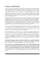
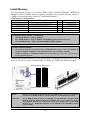
Box Included Checklist
5
5
5
5
5
5
5
Sapphire PC-AM2RX780 Motherboard
Cable for ATA 133 IDE
Sapphire Driver CD for Motherboard and Utilities
Cable for Serial ATA II
Sappphire PC-AM2RX780 Motherboard User’s Manual
Rear External I/O Shield
PCI-E X16 slot Switch Card
Environmental Protection Announcement
Do not dispose this electronic device into the trash while discarding. To minimize pollution
and ensure environment protection of mother earth, please recycle.
2
Features of motherboard
The AMD 770 Series motherboards are based on the latest AMD 770 Chipset and the SB600
chipset which supports the new generation innovative 64-bit AMD Socket AM2+ dual core
multi-tasking Socket AM2+ Athlon64 X2 processors. With an integrated low-latency
high-bandwidth DDRII memory controller and a highly-scalable Hyper Transport
technology-based system bus up to HTT 3.0 . AMD 770 Platform Processor Chipset
motherboard series deliver the outstanding system performance and professional desktop
platform solution with the advantages of new generation 64-bit AMD Socket AM2+ Phenum /
Athlon64 / Sempron processors .
The AMD 770 Series motherboards support new generation Socket AM2+ processors with an
integrated DDRII memory controller which provides with 266MHz / 333MHz/ 400MHz /
533MHz memory clock frequency for Dual channel DDRII533 / DDRII667 / DDRII800 /
DDRII1066 Module up to 8.0GB. The motherboard is embedded with SB600 chipset of
providing ULTRA ATA 133 connectors and Serial ATA2 with RAID 0 ,1, 10,0+1 functions
which support up to two IDE and four Serial ATA2 devices to accelerate hard disk drives and
guarantee the data security without failure in advanced computing performance.
The 770 series motherboards provide gigabit LAN function with Marvell M88E8056 PCI-E
LAN which supports10/100/1000Mbps data transfer rate. And the embedded Azalia 8-channel
Audio CODEC is fully compatible with Sound Blaster Pro® standards that offers you with
the home cinema quality and satisfying software compatibility.
The motherboards offer two PCI-Express 2.0 x16 graphics slot providing 8Gbyte/sec data
transfer rate at each relative direction which gets 2 times of bandwidth more than PCI-Express
and it’s up to a peak concurrent bandwidth of 16Gbyte/sec at full speed to guarantee the
ultimate GPU computing performance. Two 32-bit PCI slots guarantee the rich connectivity
for the I/O of peripherals. Two PCI Express 2.0 x1 I/O slots offer 1Gbyte/sec concurrently
bandwidth; the motherboards are designed of tackling the profuse multimedia requirements
nowadays.
Embedded USB controller as well as capability of expanding to 10 of USB2.0 functional
ports delivering 480Mb/s bandwidth and rich connectivity, these motherboards meet the
future USB demands which are also equipped with hardware monitor function on system to
monitor and protect your system and maintain your non-stop business computing.
Some special features---CPU Thermal Throttling/ CPU Vcore 7-shift/ CPU Smart Fan/in
this motherboard are designed for power user to use the over-clocking function in more
flexible ways. But please be caution that the over-clocking maybe cause the fails in system
reliabilities. This motherboard provides the guaranteed performance and meets the demands
of the next generation computing. But if you insist to gain more system performance with
variety possibilities of the components you choose, please be careful and make sure to read
the detailed descriptions of these value added product features, please get them in the coming
section.
3
Special Features of Motherboard
CPU Thermal Throttling Technology---(The CPU Overheat Protection Technology)
To prevent the increasing heat from damage of CPU or accidental shutdown while at high
workload, the CPU Thermal Throttling Technology will force CPU to enter partially idle
mode from 87.5% to 12.5% according to preset CPU operating temperature in BIOS (from 40
℃ to 90℃). When the system senses the CPU operating temperature reaching the preset
value, the CPU operating bandwidth will be decreased to the preset idle percentage to cool
down the processor. When at throttling mode the beeper sound can be optionally selected to
indicate it is in working. (For detail operating please read Section 3-11 Bi-turbo
Configuration)
CPU Smart Fan---( The Noise Management System )
It’s never been a good idea to gain the performance of your system by sacrificing its acoustics.
CPU Smart Fan Noise Management System is the answer to control the noise level needed for
now-a-day’s high performance computing system. The system will automatically increase the
fan speed when CPU operating loading is high, after the CPU is in normal operating condition,
the system will low down the fan speed for the silent operating environment. The system can
provide the much longer life cycle for both CPU and the system fans for game use and
business requirements.
CPU Vcore 7-Shift--- (Shift to Higher Performance)
The CPU voltage can be adjusted up by 31 steps for the precisely over-clocking of extra
demanding computing performance.
OC-CON ---(High-polymer Solid Electrolysis Aluminum Capacitors)
The working temperature is from 55 degrees Centigrade below zero to 125 degrees
Centigrade, OC-CON capacitors possess superior physical characteristics that can be while
reducing the working temperature between 20 degrees Centigrade each time, intact extension
10 times of effective product operation lives, at not rising degrees Centigrade of working
temperatures each time a relative one, life of product decline 10% only too.
4
Specification
Spec
Design
Chipset
CPU Socket AM2+
Memory Socket
Description
∗
*
*
∗
∗
∗
∗
∗
Expansion Slot
∗
∗
∗
Integrate IDE and
Serial ATA2 RAID
∗
LAN
∗
∗
8 CH-Audio
∗
∗
∗
BIOS
Multi I/O
∗
∗
∗
∗
∗
∗
∗
∗
∗
∗
ATX form factor 4 layers PCB size: 30.5cm*22.0cm
AMD 770 North Bridge Chipset
AMD SB600 South Bridge Chipset
Support 64bit AMD Athlon64 940-Pin package utilizes
Flip-Chip Pin Grid Array package processor
Support for future AMD Athlon64 940-pin Dual –Core
Athlon 64x2 processor, Athlon 64 & Sempron Processors and
the latest AMD Phenom™ FX, AMD Phenom™ processors
with HTT 3.0
240-pin DDRII Module socket x 4
Support 4pcs DDRII400 / DDRII533 / DDRII667 / DDRII800
/ DDRII 1066 Modules Expandable to 8.0GB
PCI-Express x16 slot 2pcs delivers up to 16GB/s of concurrent
bandwidth
PCI-Express x1 slot 2pcs delivers up to 1GB/s of concurrent
bandwidth
32-bit PCI slot x 2pcs at 133MHz
One IDE controllers support PCI Bus Mastering, ATA
PIO/DMA and the ULTRA DMA 33/66/100/133 functions that
deliver the data transfer rate up to 133 MB/s.
Four Serial ATA2 ports provide 300 MB/sec data transfer rate
with RAID 0, 1, 0+1,10 functions.
Integrated Marvell M88E8056 PCI-E gigabit LAN
Support Fast Ethernet LAN function providing 10/100/1000
Mbps data transfer rate
Realtek ALC883 Azalia 8-channel Audio Codec integrated
Support 8-channel 3D surround & Positioning Audio
Audio driver and utility included
Award 8MB Flash SPI ROM
PS/2 keyboard and PS/2 mouse connectors
Floppy disk drive connector x1
Parallel port header x1
Serial port header x1
1 * SPDIF 4-pin Block
SPDIF In/Out Connector
IR connecter with 5-pin block x1
USB2.0 port x 4 and headers x 3
Audio connector (Line-in, Line-out, MIC/ 8CH Audio)
5
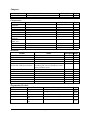
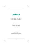
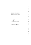
Layout Diagram & Jumper Setting
RJ45 LAN
USB1
Line-IN
Surrback
Coaxial In/Out
Line-OUT
CEN/LFE
PS/2 Mouse
PS/2 Keyboard
Surround
MIC-IN
COM Connector
UL2
KB/MS Power On Jumper(JP1)
ATX 12V Power Connector
CPU FAN
PS2 KB/Mouse Port
Coaxial In/Out
CPU Socket AM2+
DDR2 Socket x 4
COM Connector
USB Port
ATX Power Conn.
RJ45 Over
USB Connector
Audio Connector
SYSFAN1
4-pin PWR Connector
ATA 133 IDE
Conn.(IDE1)
AMD 770Chipset
PCI Express x16
AMD SB600
Marvell M88E8056
PCI Express x1
Serial-ATAII Connector
(SATA II 1, 2,3,4)
CD Audio In
PCI Express x16
HDMI-SPDIF
8MBit Flash SPI
ROM BIOS
Clear CMOS (JBAT)
Realtek ALC883
Audio Decode
Floppy Connector
PCI Slots
Speaker Connector
Power LED Connector
Front Panel Audio
Parallel Header IR Connector
USB headers
6
SYS FAN2
Front Panel Connector
Jumpers
Jumper
JBAT
JP1
Name
CMOS RAM Clear
Keyboard/USB Power On Enabled/Disabled
Description
3-pin Block
3-pin Block
Page
P.7
P.8
Connectors
Connector
ATXPWR
ATX12V
PS2 KB/MS
UL1for USB
UL1 for LAN
CN1 for USB
CN2,CN3for Audio
Connector
SPDIF-In
SPDIF-Out
FDD
IDE1
SATA1~4
Name
ATX Power Connector
Description
24-pin Block
Page
P.13
ATX 12V Power Connector
PS/2 Mouse & PS/2 Keyboard Connector
USB2.0 Port Connector
LAN Port Connector
USB2.0 Port Connector
8-CH HD Audio Connector
8-pin Block
6-pin Female
4-pin Connector
RJ-45 Connector
4-pin Connector
6-pin
P.13
P.14
P.14
P.14
P.14
P.14
Coaxial In/Out Connector
1 pin
P.18
Floppy Driver Connector
Primary IDE Connector
Serial ATAII IDE Connector
34-pin Block
40-pin Block
7-pin Connector
P.15
P.15
P.15
Headers
Header
AUDIO
USB1, USB2,USB3
SPEAK
PWR LED
JW_FP
(Reset/IDE LED/Power Button)
SYSFAN1, SYSFAN2,
CPUFAN
CDIN
IR
PARALLEL
COM1
SPDIF
Name
SPEAKER, MIC header
USB Port Headers
PC Speaker connector
Power LED
Front Panel Header
(including IDE activity LED/Reset switch /
Power On Button lead)
FAN Headers
FAN Header
CD Audio-In Header
IR infrared module Headers
Parallel Port Header
Serial Port COM1 Header
SPDIF In/Out header
Description
9-pin Block
9-pin Block
4-pin Block
3-pin Block
9-pin Block
Page
P.16
P.16
P.16
P.16
P.16
3-pin Block
4-pin Block
4-pin Block
5-pin Block
25-pin Block
9-pin Block
9-pin Block
P.17
P.17
P.17
P.18
P.18
P.18
P.18
Expansion Sockets
Socket/Slot
ZIF Socket AM2+
DIMM1~4
PCI1∼ PCI4
PE1,PE4
PE2,PE2
Name
CPU Socket
DDRII Module Socket
PCI Slots
PCI-Express2.0
x16
Slot
PCI-Express2.0
x1
Slot
Description
940-pin mPGAB Athlon64 CPU Socket
240-pin DDRII Module Socket
32-bit PCI Local Bus Expansion slots
PCI-Express2.0 x16 Expansion Slot
Page
P.9
P.10
P.12
P.12
PCI-Express2.0 x1
P.12
7
Expansion Slot
Hardware Installation
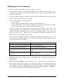
Hardware installation Steps
Before using your computer, you had better complete the following steps:
1. Check motherboard jumper setting
2. Install CPU and Fan
3. Install System Memory (DIMM)
4. Install Expansion cards
5. Connect IDE and Front Panel /Back Panel cable
6. Connect ATX Power cable
7. Power-On and Load Standard Default
8. Reboot
9. Install Operating System
10. Install Driver and Utility
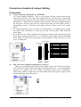
Checking Motherboard’s Jumper Setting
(1)
CMOS RAM Clear (3-pin) : JBAT
A battery must be used to retain the motherboard configuration in CMOS RAM short 1-2
pins of JBAT to store the CMOS data.
To clear the CMOS, follow the procedure below:
1. Turn off the system and unplug the AC power
2. Remove ATX power cable from ATX power connector
3. Locate JBAT and short pins 2-3 for a few seconds
4. Return JBAT to its normal setting by shorting pins 1-2
5. Connect ATX power cable back to ATX power connector
Note: When should clear CMOS
1. Troubleshooting
2. Forget password
3. After over clocking system boot fail
JBAT
JBAT
1-2 Closed
Normal
2-3 Closed
CMOS RAM Clear Setting
8
Clear CMOS
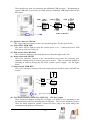
(2)
Keyboard function Enabled/Disabled: JP1
Install CPU
About AMD Athlon64 Socket AM2 CPU
This motherboard provides a 940-pin surface mount, Zero Insertion Force (ZIF) socket,
referred to as the mPGA940 socket supports AMD Athlon64 processor in the 940 Pin package
utilizes Flip-Chip Pin Grid Array package technology.
The CPU that comes with the motherboard should have a cooling FAN attached to prevent
overheating. If this is not the case, then purchase a correct cooling FAN before you turn on
your system.
WARNING!
Be sure that there is sufficient air circulation across the processor’s
heatsink and CPU cooling FAN is working correctly, otherwise it may
cause the processor and motherboard overheat and damage, you may install
an auxiliary cooling FAN, if necessary.
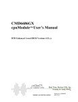
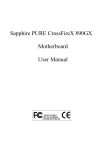
To install a CPU, first turn off your system and remove its cover. Locate the ZIF socket and
open it by first pulling the level sideways away from the socket then upward to a 90-degree
angle. Insert the CPU with the correct orientation as shown below. The notched corner
should point toward the end of the level. Because the CPU has a corner pin for two of the
four corners, the CPU will only fit in the orientation as shown.
Socket AM2
Colden Arrow
CPU ZIF mPGAB Socket
When you put the CPU into the ZIF socket, No force require to insert of the CPU, then press
the level to Locate position slightly without any extra force.
9
Install Memory
This motherboard provides four 240-pin DDR2 DUAL INLINE MEMORY MODULES
(DIMM) sockets for DDR2 memory expansion available from minimum memory volume of
128MB to maximum memory volume of 4.0GB DDR SDRAM.
Valid Memory Configurations
Bank
240-Pin DIMM
PCS
Total Memory
Bank 0, 1 (DIMM1)
Bank 2, 3 (DIMM2)
Bank 4, 5 (DIMM3)
Bank 6,7 (DIMM4)
Total
DDR2 533/DDR2 667/DDR2 800
DDR2 533/DDR2 667/DDR2 800
DDR2 533/DDR2 667/DDR2 800
DDR2 533/DDR2 667/DDR2 800
System Memory (Max 8.0GB)
X1
X1
X1
X1
4
128MB∼2.0GB
128MB∼2.0GB
128MB∼2.0GB
128MB∼2.0GB
128MB∼8.0GB
Recommend DIMM Module Combination
1.
2.
3.
One DIMM Module ----Plug in DIMM1
Two DIMM Modules---Plug in DIMM1 and DIMM2 for Dual channel function
Four DIMM Modules---Plug in DIMM1/DIMM2/DIMM3/DIMM4.
For Dual channel Limited!
4.
5.
Dual channel function only supports when 2 DIMM Modules plug in either both DIMM1 &
DIMM2or DIMM3 &DIMM4, or four DIMM Modules plug in DIMM1~DIMM4.
DIMM1 & DIMM2, or DIMM3& DIMM4 must be the same type, same size, same frequency
for dual channel function.
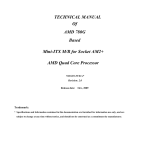
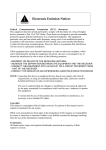
Install DDR SDRAM modules to your motherboard is not difficult, you can refer to figure
below to see how to install a 240-Pin DDR2 533/DDR2 667/DDR2 800/ SDRAM module.
DIMM1 (BANK6+BANK7)
DIMM2 (BANK4+BANK5)
DIMM3 (BANK2+BANK3)
DIMM4 (BANK0+BANK1)
DIMM3 & DIMM4: Dual Channel 2
DIMM1 & DIMM2: Dual Channel 1
NOTE!
When you install DIMM module fully into the DIMM socket the eject tab should be
locked into the DIMM module very firmly and fit into its indention on both sides.
WARNING!
For the DDR SDRAM CLOCK is set at 400MHz, use only DDR2 800- compliant DDR2
Modules. When this motherboard operate at 400Mhz, most system will not even boot if
non-compliant modules are used because of the strict timing issues, if your DDR
Modules are not DDR2 800-compliant, set the SDRAM clock to 200MHz to ensure
system stability.
10
Expansion Cards
WARNING!
Turn off your power when adding or removing expansion cards or other
system components. Failure to do so may cause severe damage to both
your motherboard and expansion cards.
Procedure For Expansion Card Installation
1. Read the documentation for your expansion card and make any necessary hardware or
software setting for your expansion card such as jumpers.
2. Remove your computer’s cover and the bracket plate on the slot you intend to use.
3. Align the card’s connectors and press firmly.
4. Secure the card on the slot with the screen you remove above.
5. Replace the computer system’s cover.
6. Set up the BIOS if necessary.
7. Install the necessary software driver for your expansion card.
Assigning IRQs For Expansion Card
Some expansion cards need an IRQ to operate. Generally, an IRQ must exclusively assign
to one use. In a standard design, there are 16 IRQs available but most of them are already in
use.
Standard Interrupt Assignments
IRQ
0
1
2
3*
4*
5*
6*
7*
8
9*
10 *
11 *
12 *
13
14 *
15 *
Priority
N/A
N/A
N/A
8
9
6
11
7
N/A
10
3
2
4
N/A
5
1
Standard function
System Timer
Keyboard Controller
Programmable Interrupt
Communications Port (COM2)
Communications Port (COM1)
Sound Card (sometimes LPT2)
Floppy Disk Controller
Printer Port (LPT1)
System CMOS/Real Time Clock
ACPI Mode when enabled
IRQ Holder for PCI Steering
IRQ Holder for PCI Steering
PS/2 Compatible Mouse Port
Numeric Data Processor
Primary IDE Channel
Secondary IDE Channel
* These IRQs are usually available for ISA or PCI devices.
Interrupt Request Table For This Motherboard
Interrupt request are shared as shown the table below:
INT A
Slot 1
Slot 2
Onboard USB 2
Onboard USB 3
HD Audio/MC97
INT B
√
√
INT C
√
√
√
11
INT D
INT E
INT F
INT G
INT H
IMPORTANT!
If using PCI cards on shared slots, make sure that the drivers support “Shared IRQ” or
that the cards don’t need IRQ assignments. Conflicts will arise between the two PCI
groups that will make the system unstable or cards inoperable.
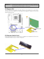
PCI Express Slot
Two PCI-Express2.0 x16 graphics slot offers 8Gbyte/sec data transfer rate at each relative
direction. and two PCI-Express 2.0 x1 PCI Express Slot. Support PCI Express VGA card, and
other PCI Express device.
PCI-E x1 Slot
PCI-E x16 by 8Slot
32-bit PCI Slot
PCI Express Switch Card
Install PCI-E Switch Card to PCI-Express2.0 x16 graphics slot can double PCI-E X16 VGA
card installed transfer rate up to 16 lane; 16Gbyte/sec
12
Connectors, Headers & Jumper Setting
Connectors
(1)
Power Connector (24-pin block) : ATXPWR
ATX Power Supply connector. This is a new defined 24-pins connector that usually
comes with ATX case. The ATX Power Supply allows to use soft power on momentary
switch that connect from the front panel switch to 2-pins Power On jumper pole on the
motherboard. When the power switch on the back of the ATX power supply turned on,
the full power will not come into the system board until the front panel switch is
momentarily pressed. Press this switch again will turn off the power to the system
board.
** We recommend that you use an ATX 12V Specification 2.0-compliant power supply
unit (PSU) with a minimum of 350W power rating. This type has 24-pin and 4-pin
power plugs.
** If you intend to use a PSU with 20-pin and 4-pin power plugs, make sure that the 20-pin
power plug can provide at least 15A on +12V and the power supply unit has a minimum
power rating of 350W. The system may become unstable or may not boot up if the
power is inadequate.
ROW1 ROW2
PIN
ROW1 ROW2
Pin 1
Pin 1
20-Pin
24-Pin
ROW1
ROW2
1
3.3V
3.3V
2
3.3V
-12V
3
GND
GND
4
5V
Soft Power On
5
GND
GND
6
5V
GND
7
GND
GND
8
Power OK
-5V
9
+5V (for Soft Logic)
+5V
10
+12V
+5V
11
+12V
+5V
12
+3V
GND
(2) ATX 12V Power Connector (8-pin block) : ATX12V
This is a new defined 8-pins connector that usually comes with ATX Power Supply.
The ATX Power Supply which fully support Pentium 4 processor must including this
connector for support extra 12V voltage to maintain system power consumption.
Without this connector might cause system unstable because the power supply can not
provide sufficient current for system.
Pin 1
13
(3) PS/2 Mouse & PS/2 Keyboard Connector: KB
The connectors are for PS/2 keyboard and PS/2 Mouse.
(4) USB Port connector: USB4
The connectors are 4-pin connectors that connect USB devices to the system board.
(5) LAN Port connector: UL1
This connector is standard RJ45 connector for Network
The USBLAN1 support 10M/100Mb/1000Mb s data transfer rate
(6) Audio Line-In, Lin-Out, MIC Connector : CN2,CN3
This Connector are 3 phone Jack for LINE-OUT, LINE-IN, MIC
Audio input to sound chip
Line-in : (BLUE)
Audio output to speaker
Line-out : (GREEN)
Microphone Connector
MIC : (PINK)
Line-In
PS/2 Mouse
Coaxial In/Out
COM Connector
Surrback
Line-Out
CEN/LFE
Surround
PS/2 Keyboard
USB1
UL1
MIC-IN
(7) Floppy drive Connector (34-pin block): FDD
This connector supports the provided floppy drive ribbon cable. After connecting the
single plug end to motherboard, connect the two plugs at other end to the floppy drives.
FDD
Pin 1
Floppy Drive Connector
(8) Primary IDE Connector (40-pin block): IDE1
This connector supports the provided IDE hard disk ribbon cable. After connecting the
single plug end to motherboard, connect the two plugs at other end to your hard disk(s).
If you install two hard disks, you must configure the second drive to Slave mode by
setting its jumpers accordingly. Please refer to the documentation of your hard disk for
the jumper settings.
14
IDE1
Pin 1
Primary IDE Connector
• Two hard disks can be connected to each connector. The first HDD is referred to as the
“Master” and the second HDD is referred to as the “Slave”.
• For performance issues, we strongly suggest you don’t install a CD-ROM or DVD-ROM
drive on the same IDE channel as a hard disk. Otherwise, the system performance on this
channel may drop.
(9) Serial-ATAII Port connector: SATAII1 / SATAII2/ SATAII3/ SATAII4
This connector supports the provided Serial ATA2 IDE hard disk cable to connecting the
motherboard and serial ATAII hard disk.
SATA1
SATA2
SATA3
SATA4
Serial-ATA2 Port Connector
Headers
AUDIO
AUD_GND
AUD_GND
AUD_JD 9
AUD_GND
(1) Line-Out/MIC Header for Front Panel (9-pin): AUDIO
This header connect to Front Panel Line-out, MIC connector with cable.
2
10
Pin 1
MIC2-L
MIC2-R
LINEOUUT2-R
SENSE-FB
LINEOUT2-L
9
Line-Out, MIC Headers
(2) USB Port Headers (9-pin) : USB1/USB2/USB3
15
+DATA
GND
OC
VCC
-DATA
+DATA
GND
+DATA
GND
VCC
-DATA
+DATA
GND
-DATA
VCC
VCC
Pin 1
Pin 1
Pin 1
USB3
-DATA
+DATA
GND
OC
VCC
USB2
-DATA
+DATA
GND
OC
-DATA
USB1
VCC
These headers are used for connecting the additional USB port plug. By attaching an
option USB cable, your can be provided with two additional USB plugs affixed to the
back panel.
USB Port Headers
GND
PWRBTN
PWRBTN
GND
JW FP
RSTSW
NC
PWRLED
Pin 1
PWRLED
VCC5
PWR LED
(3) Speaker connector: SPEAK
This 4-pin connector connects to the case-mounted speaker. See the figure below.
(4) Power LED: PWR LED
The Power LED is light on while the system power is on. Connect the Power LED
from the system case to this pin.
(5) IDE Activity LED: HD LED
This connector connects to the hard disk activity indicator light on the case.
(6) Reset switch lead: RESET
This 2-pin connector connects to the case-mounted reset switch for rebooting your
computer without having to turn off your power switch. This is a preferred method of
rebooting in order to prolong the lift of the system’s power supply. See the figure
below.
(7) Power switch: PWR BTN
This 2-pin connector connects to the case-mounted power switch to power ON/OFF the
system.
SPEAK
RESET
VCC5
HDDLE
HDLED
VCC5
GND
Pin 1
SPKR
NC
Pin 1
System Case Connections
(8) FAN Power Headers: SYSFAN1, SYSFAN2, CPUFAN (4-pin)
These connectors support cooling fans of 350mA (4.2 Watts) or less, depending on the
fan manufacturer, the wire and plug may be different. The red wire should be positive,
while the black should be ground. Connect the fan’s plug to the board taking into
consideration the polarity of connector.
16
CPUFAN IN
CPUFAN OUT
GND
+12V
CPUFAN
4
1
SYSFAN1
3
1
SYSFAN2
3
1
FAN Power Headers
(9) CD Audio-In Headers (4-pin) : CDIN
CDIN are the connectors for CD-Audio Input signal. Please connect it to CD-ROM
CD-Audio output connector.
CDIN
4
1
CD Audio-In Headers
IR infrared module Headers (5-pin) : IR
This connector supports the optional wireless transmitting and receiving infrared
module. You must configure the setting through the BIOS setup to use the IR function.
IR
GND
IRRX
(10)
2
6
5
NC
VCC5
IRTX
Pin 1
IR infrared module Headers
(11)
Parallel Port Connector (25-pin female): PARALLEL
The On-board Parallel Port can be disabled through the BIOS SETUP. Please refer to
Chapter 3 “INTEGRATED PERIPHERALS SETUP” section for more detail
information.
17
Pin 1
PARALLEL Header
(13)
HDMI-SPDIF
The SPDIF output is capable of providing digital audio to external speakers or
compressed AC3 data to an external Dolby digital decoder. Use this feature only when
your stereo system has digital input function. Use SPDIF IN feature only when your
device has digital output function.
18
Starting Up Your Computer
1. After all connection are made, close your computer case cover.
2. Be sure all the switch are off, and check that the power supply input voltage is set to
proper position, usually in-put voltage is 220V∼240V or 110V∼120V depending on your
country’s voltage used.
3. Connect the power supply cord into the power supply located on the back of your system
case according to your system user’s manual.
4. Turn on your peripheral as following order:
a. Your monitor.
b. Other external peripheral (Printer, Scanner, External Modem etc…)
c. Your system power. For ATX power supplies, you need to turn on the power supply
and press the ATX power switch on the front side of the case.
5. The power LED on the front panel of the system case will light. The LED on the
monitor may light up or switch between orange and green after the system is on. If it
complies with green standards or if it is has a power standby feature. The system will
then run power-on test. While the test are running, the BIOS will alarm beeps or
additional message will appear on the screen.
If you do not see any thing within 30 seconds from the time you turn on the power. The
system may have failed on power-on test. Recheck your jumper settings and connections
or call your retailer for assistance.
Beep
Meaning
One short beep when displaying logo
No error during POST
Long beeps in an endless loop
No DRAM install or detected
One long beep followed by three short
beeps
Video card not found or video card memory
bad
High frequency beeps when system is
working
CPU overheated
System running at a lower frequency
6. During power-on, press <Delete> key to enter BIOS setup. Follow the instructions in
BIOS SETUP.
7. Power off your computer: You must first exit or shut down your operating system
before switch off the power switch. For ATX power supply, you can press ATX power
switching after exiting or shutting down your operating system. If you use Windows 9X,
click “Start” button, click “Shut down” and then click “Shut down the computer?”
The power supply should turn off after windows shut down.
19
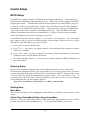
Useful Setup
BIOS Setup
The BIOS is a program located on a Flash Memory on the motherboard. This program is a
bridge between motherboard and operating system. When you start the computer, the BIOS
program gain control. The BIOS first operates an auto-diagnostic test called POST (power on
self test) for all the necessary hardware, it detects the entire hardware device and configures
the parameters of the hardware synchronization. Only when these tasks are completed done
it gives up control of the computer to operating system (OS). Since the BIOS is the only
channel for hardware and software to communicate, it is the key factor for system stability,
and in ensuring that your system performance as its best.
In the BIOS Setup main menu of Figure 3-1, you can see several options. We will explain
these options step by step in the following pages of this chapter, but let us first see a short
description of the function keys you may use here:
•
Press <Esc> to quit the BIOS Setup.
•
Press ↑ ↓ ← → (up, down, left, right) to choose, in the main menu, the option you want to
confirm or to modify.
•
Press <F10> when you have completed the setup of BIOS parameters to save these
parameters and to exit the BIOS Setup menu.
•
Press Page Up/Page Down or +/– keys when you want to modify the BIOS parameters for
the active option.
Entering Setup
Power on the computer and by pressing <Del> immediately allows you to enter Setup.
If the message disappears before your respond and you still wish to enter Setup, restart the
system to try again by turning it OFF then ON or pressing the “RESET” button on the system
case. You may also restart by simultaneously pressing <Ctrl>, <Alt> and <Delete> keys. If
you do not press the keys at the correct time and the system does not boot, an error message
will be displayed and you will again be asked to
Press <F1> to continue, <Ctrl-Alt-Esc> or <Del> to enter Setup
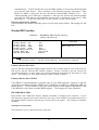
Getting Help
Main Menu
The on-line description of the highlighted setup function is displayed at the bottom of the
screen.
Status Page Setup Menu/Option Page Setup Menu
Press F1 to pop up a small help window that describes the appropriate keys to use and the
possible selections for the highlighted item. To exit the Help Window, press <Esc>.
20
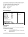
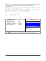
The Main Menu
Once you enter Award® BIOS CMOS Setup Utility, the Main Menu (Figure 3-1) will appear
on the screen. The Main Menu allows you to select from fourteen setup functions and two
exit choices. Use arrow keys to select among the items and press <Enter> to accept or enter
the sub-menu.
Phoenix – AwardBIOS CMOS Setup Utility
Standard CMOS Features
Power User Overclock settings
Advanced BIOS Features
CPU Thermal Throttling Setup
Advanced Chipset Features
Password Settings
Integrated Peripherals
Load Fail-Safe Defaults
Power Management Setup
Load Optimized Defaults
Miscellaneous control
Save & Exit Setup
PC Health Status
Exit Without Saving
Esc : Quit
F9 : Menu in BIOS
F10 : Save & Exit Setup
↑↓→← : Select Item
Standard CMOS Features
Use this Menu for basic system configurations.
Advanced BIOS Features
Use this menu to set the Advanced Features available on your system.
Advanced Chipset Features
Use this menu to change the values in the chipset registers and optimize your system’s
performance.
Integrated Peripherals
Use this menu to specify your settings for integrated peripherals.
Power Management Setup
Use this menu to specify your settings for power management.
PC Health Status
This entry shows your PC health status.
CPU Thermal Throttling Setting
The selection is set for activating the active CPU Thermal Protection by flexible CPU loading
adjustment in the arrange of temperature you define.
Load Fail-Safe Defaults
This menu uses a minimal performance setting, but the system would run in a stable way.
Load Optimized Defaults
Use this menu to load the BIOS default values these are setting for optimal performances system
operations for performance use.
21
Password Setting
This entry for setting Supervisor password and User password
Save & Exit Setup
Save CMOS value changes to CMOS and exit setup.
Exit Without Saving
Abandon all CMOS value changes and exit setup.
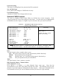
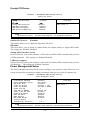
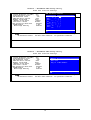
Standard CMOS Features
The items in Standard CMOS Setup Menu are divided into several categories. Each
category includes no, one or more than one setup items. Use the arrow keys to highlight the
item and then use the <PgUp> or <PgDn> keys to select the value you want in each item.
Phoenix – AwardBIOS CMOS Setup Utility
Standard CMOS Features
Date (mm.dd.yy)
00* 00 * 00
Time (hh:mm:ss)
16 : 48 : 35
> IDE Channel 0 Master
> IDE Channel 0 Slave
SATA
SATA
SATA
SATA
Channel
Channel
Channel
Channel
1
2
3
4
Drive A
Halt On
Base Memory
Extended Memory
Total Memory
Item Help
None
None
Menu Level >
Change the day, month,
year and century
None
None
None
None
1.44M, 3.5 in.
All Errors
640K
1047552K
1048476K
↑↓→← Move Enter:Select +/-/PU/PD:Value F10:Save ESC:Exit F1:General Help
F5:Previous Values
F6:Fail-safe Defaults
F7:Optimized Defaults
Date
The date format is <day><month><date><year>.
Day Day of the week, from Sun to Sat, determined by BIOS. Read-only.
The month from Jan. through Dec.
Month
The date from 1 to 31 can be keyed by numeric function keys.
Date
The year depends on the year of the BIOS.
Year
Time
The time format is <hour><minute><second>.
IDE Channel 0 Master / Channel 0 Slave
SATA Channel 1, 2, 3, 4
Press PgUp/<+> or PgDn/<–> to select Manual, None, Auto type. Note that the
specifications of your drive must match with the drive table. The hard disk will not work
properly if you enter improper information for this category. If the type of hard disk drives
is not matched or listed, you can use Manual to define your own drive type manually.
22
If you select Manual, related information is asked to be entered to the following items. Enter
the information directly from the keyboard. This information should be provided in the
documentation from your hard disk vendor or the system manufacturer.
If the controller of HDD interface is SCSI, the selection shall be “None”.
If the controller of HDD interface is CD-ROM, the selection shall be “None”
Access Mode The settings are Auto Normal, Large, and LBA.
number of cylinders
Cylinder
number of heads
Head
write precomp
Precomp
Landing Zone landing zone
number of sectors
Sector
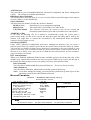
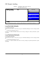
Advanced BIOS Features
Phoenix – AwardBIOS CMOS Setup Utility
Advanced BIOS Features
CPU Feature
Press Enter
Hard Disk Boot Priority
Press Enter
Virus Warning
Disabled
CPU Internal Cache
Enabled
External Cache
Enabled
Quick Power On Self Test
Enabled
First Boot Device
Hard Disk
Second Boot Device
CD-ROM
Third Boot Device
Floppy
Boot other Device
Enabled
Boot Up Floppy Seek
Disable
Boot Up NumLock Status
On
Gate A20 option
[fast]
Typematic Rate Setting
Disabled
* Typematic Rate (Chars/Sec)
6
*Typematic Delay (Msec)
250
Security Option
Setup
APIC Mode
Enabled
MPS Version Control For OS
1.4
OS Select For DRAM > 64MB
Non-OS2
HDD S.M.A.R.T. Capability
Disabled
Small Logo (EPA ) Show
Enabled
Item Help
Menu Level >
↑↓→← Move Enter:Select +/-/PU/PD:Value F10:Save ESC:Exit F1:General Help
F5:Previous Values
F6:Fail-safe Defaults
F7:Optimized Defaults
Hard Disk Boot Priority
The selection is for you to choose the hard disk drives priorities to boot from.
Virus Warning
Allows you to choose the VIRUS Warning feature for IDE Hard Disk boot sector protection.
If this function is enabled and someone attempt to write data into this area, BIOS will show a
warning message on screen and alarm beep.
Disabled (default) No warning message to appear when anything attempts to access the
boot sector or hard disk partition table.
Activates automatically when the system boots up causing a warning
Enabled
message to appear when anything attempts to access the boot sector
of hard disk partition table.
CPU Internal Cache
23
The default value is Enabled.
Enable cache
Enabled (default)
Disable cache
Disabled
Note:
The internal cache is built in the processor.
External Cache
Choose Enabled or Disabled. This option enables the Level 2 cache memory.
Quick Power On Self-Test
This category speeds up Power On Self Test (POST) after you power on the computer. If
this is set to Enabled. BIOS will shorten or skip some check items during POST.
Enable quick POST
Enabled (default)
Normal POST
Disabled
First/Second/Third/Fourth Boot Device
The BIOS attempts to load the operating system from the devices in the sequence selected in
these items. The settings are Floppy, LS/ZIP, HDD-0/HDD-1/HDD-3, SCSI, CDROM,
LAD and Disabled.
Boot Up Floppy Seek
During POST, BIOS will determine if the floppy disk drive installed is 40 or 80 tracks.
360K type is 40 tracks while 760K, 1.2M and 1.44M are all 80 tracks.
Boot Up NumLock Status
The default value is On.
On (default) Keypad is numeric keys.
Keypad is arrow keys.
Off
Gate A20 Option
The A20 signal is controlled by keyboard controller or chipset hardware.
Normal
The A20 signal is controlled by port 92 or chipset specific method.
Fast (default)
Typematic Rate Setting
Keystrokes repeat at a rate determined by the keyboard controller. When enabled, the
typematic rate and typematic delay can be selected. The settings are: Enabled/Disabled.
Typematic Rate (Chars/Sec)
Sets the number of times a second to repeat a keystroke when you hold the key down. The
settings are: 6, 8, 10, 12, 15, 20, 24, and 30.
Typematic Delay (Msec)
Sets the delay time after the key is held down before is begins to repeat the keystroke. The
settings are 250, 500, 750, and 1000.
Security Option
This category allows you to limit access to the system and Setup, or just to Setup.
The system will not boot and access to Setup will be denied if the
System
correct password is not entered at the prompt.
Setup (default) The system will boot, but access to Setup will be denied if the correct
password is not entered prompt.
ACPI Mode
This option allow you to enable the ACPI Mode (Advanced Configuration and Power
Interface ). You can choose from Enabled and Disabled.
HDD S.M.A.R.T Capability
This option allow you to enable the HDD S.M.A.R.T Capability (Self-Monitoring, Analysis
and Reporting Technology) . You can choose from Enabled and Disabled.
24
MPS Version Control For OS
1.4
This option is only valid for multiprocessor motherboards as it specifies the version of the
Multiprocessor Specification (MPS) that the motherboard will use.
OS Select For DRAM > 64MB
Allows OS2® to be used with >64MB or DRAM. Settings are Non-OS/2 (default) and OS2.
Set to OS/2 if using more than 64MB and running OS/2®.
Small Logo (EPA) Show
The selection is for you to choose the EPA small logo to show or not.
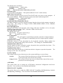
Advanced Chipset Features
The Advanced Chipset Features Setup option is used to change the values of the chipset
registers. These registers control most of the system options in the computer.
Phoenix – AwardBIOS CMOS Setup Utility
Advanced Chipset Features
DRAM Configuration
HT Link Control
PCIE Configuration
Memory Hole
System BIOS Cacheable
[press enter]
[press enter]
[press enter]
Disabled
Disabled
Item Help
Menu Level >
↑↓→← Move Enter:Select +/-/PU/PD:Value F10:Save ESC:Exit F1:General Help
F5:Previous Values
F6:Fail-safe Defaults
F7:Optimized Defaults
DRAM Configuration
Please refer to section 3-6-1
System BIOS Cacheable
Selecting Enabled allows caching of the system BIOS ROM at F0000h-FFFFFh, resulting in
better system performance. However, if any program writes to this memory area, a system
error may result. The settings are: Enabled and Disabled.
25
DRAM Configuration
Phoenix – AwardBIOS CMOS Setup Utility
DRAM Configuration
DRAM Latency (tcl)
RAS to RAS R/W Delay (tRTC)
Row precharge Time (tRP)
Minium RAS Active Time (Tras)
DRAM Command Rate
CKE base Power down Mode
CKE based powerdom
Memclock tri-stating
Memory Hole Remapping
Auto Optimize Bottom IO
*Bottom of {31:24}IO
DDRII Timing Item
Row cycle Time Item
RAS to ras Delay (Trrd)
Precharge Time (trtp)
Whrite Recovery Time (twr)
* Tw Tr Command delay
* Trfc 0 for DIMM 0
* Trfc 1 for DIMM 1
* Trfc 2 for DIMM 2
* Trfc 3 for DIMM 3
Auto
Auto
Auto
Auto
2T
Disabled
per channel
Disabled
Eabled
Enabled
DO
Disabled
26 bus clocks
5clocks
3T or 5T
6 bus clocks
3 bus clock
75ns
75ns
75ns
75ns
Item Help
Menu Level >>
↑↓→← Move Enter:Select +/-/PU/PD:Value F10:Save ESC:Exit F1:General Help
F5:Previous Values
F6:Fail-safe Defaults
F7:Optimized Defaults
CAS # Latency
When synchronous DRAM is installed, the number of clock cycles of CAS latency depends
on the DRAM timing. The settings are: Auto,3, 4 and 5.
RAS-to-CAS Delay
This field let’s you insert a timing delay between the CAS and RAS strobe signals, used when
DRAM is written to, read from, or refreshed. Fast gives faster performance; and Slow gives
more stable performance. This field applies only when synchronous DRAM is installed in
the system.
Row Precharge Time
If an insufficient number of cycles is allowed for the RAS to accumulate its charge before
DRAM refresh, the refresh may be incomplete and the DRAM may fail to retain date. Fast
gives faster performance; and Slow gives more stable performance. This field applies only
when synchronous DRAM is installed in the system.
26
HT Link Control
Phoenix – AwardBIOS CMOS Setup Utility
HT link Control
HT link
HT link
IH Flow
HT link
2x LCLK
Unit ID
Width
Frequency
Control Mode
Trislate
Mode
Clumping
Auto
Auto
Disabled
Disabled
Disabled
Disabled
Item Help
Menu Level >
↑↓→← Move Enter:Select +/-/PU/PD:Value F10:Save ESC:Exit F1:General Help
F5:Previous Values
F6:Fail-safe Defaults
F7:Optimized Defaults
PCIE Configuration
Phoenix – AwardBIOS CMOS Setup Utility
PCIE Configuration
P2P b/w Primary/Seconary
GPP Power Limit,w
>GFX Port 1
>GFX Port 2
>GPP-PE2
>GPP-P3
>GPP-PCIELAN
>NB-SB Port Features
Disabled
25
press Enter
press Enter
Press Enter
Press Enter
Press Enter
Press Enter
Item Help
Menu Level >
↑↓→← Move Enter:Select +/-/PU/PD:Value F10:Save ESC:Exit F1:General Help
F5:Previous Values
F6:Fail-safe Defaults
F7:Optimized Defaults
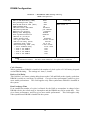
Integrated Peripherals
Phoenix – AwardBIOS CMOS Setup Utility
Integrated Peripherals
> Super Function Setup
> Onchip IDE Device
> Onchip PCI Device
Press Enter
Press Enter
Press Enter
Item Help
Menu Level >
↑↓→← Move Enter:Select +/-/PU/PD:Value F10:Save ESC:Exit F1:General Help
F5:Previous Values
F6:Fail-safe Defaults
Super IO Device
Please refer to section 3-7-1
OnChip IDE Device
Please refer to section 3-7-2
OnChip PCI Device
Please refer to section 3-7-3
27
F7:Optimized Defaults
Super IO Function Setup
Phoenix – AwardBIOS CMOS Setup Utility
Super IO Function Setup
Power on By Mouse
Power on by keyboard
Onboard FDC Controller
Onboard Serial Port1
UART Mode Select
Onboard Parallel Port
Parallel Port Mode
*ECP Mode Use DMA
PWROM After PWR-Fail
Disabled
Disabled
Enabled
3F8/IRQ4
Disabled
378/IRQ7
SPP
3
[OFF]
Menu Level >>
↑↓→← Move Enter:Select +/-/PU/PD:Value F10:Save ESC:Exit F1:General Help
F5:Previous Values
F6:Fail-safe Defaults
F7:Optimized Defaults
Onboard FDC Controller
Select Enabled if your system has a floppy disk controller (FDD) installed on the system board
and you wish to use it. If you install add-on FDC or the system has no floppy drive, select
Disabled in this field. The settings are: Enabled and Disabled.
Onboard Serial Port
Select an address and corresponding interrupt for the serial port. The settings are: 3F8/IRQ4,
2E8/IRQ3, 3E8/IRQ4, 2F8/IRQ3, Disabled, Auto.
UART Mode Select
This item allows you to determine which InfraRed(IR) function of the onboard I/O chip, this
functions uses.
IrDA Duplex Mode
This field is available when UART Mode is set to either ASKIR or IrDA. This item enables you
to determine the infrared function of the onboard infrared chip. The options are Full and Half
(default). Full-duplex means that you can transmit and send information simultaneously.
Half-duplex is the transmission of data in both directions , but only one direction at a time.
Onboard Parallel Port
There is a built-in parallel port on the on-board Super I/O chipset that Provides Standard, ECP,
and EPP features. It has the following option:
Disabled
Line Printer port 0
(3BCH/IRQ7)/
Line Printer port 2
(278H/IRQ5)/
Line Printer port 1
(378H/IRQ7)
Parallel Port Mode
SPP
: Standard Parallel Port
EPP
: Enhanced Parallel Port
ECP : Extended Capability Port
SPP/EPP/ECP/ECP+EPP
To operate the onboard parallel port as Standard Parallel Port only, choose “SPP.” To
operate the onboard parallel port in the EPP modes simultaneously, choose “EPP.” By
choosing “ECP”, the onboard parallel port will operate in ECP mode only. Choosing
“ECP+EPP” will allow the onboard parallel port to support both the ECP and EPP modes
28
simultaneously. The ECP mode has to use the DMA channel, so choose the onboard parallel
port with the ECP feature. After selecting it, the following message will appear: “ECP
Mode Use DMA” at this time, the user can choose between DMA channels 3 to 1. The
onboard parallel port is EPP Spec. compliant, so after the user chooses the onboard parallel
port with the EPP function, the following message will be displayed on the screen: “EPP
Mode Select.” At this time either EPP 1.7 spec. or EPP 1.9 spec. can be chosen.
Poweron After Power Failure
This determines the manner when the power recovery after power failure. The setting are: Off,
On.
Onchip IDE Function
Phoenix – AwardBIOS CMOS Setup Utility
OnChip IDE Function
IDE DMA transfer access
Primary Master PIO
Primary Slave
PIO
Primary Master UDMA
Primary Slave
UDMA
Onchip SATA Controller
Onchip SATA Type
IDE HDD Block Mode
Enabled
Auto
Auto
Auto
Auto
Enabled
Native IDE
Enabled
Item Help
Menu Level >>
↑↓→← Move Enter:Select +/-/PU/PD:Value F10:Save ESC:Exit F1:General Help
F5:Previous Values
F6:Fail-safe Defaults
F7:Optimized Defaults
Primary Master/Slave PIO
The two IDE PIO (Programmed Input/Output) fields let you set a PIO mode (0-2) for each of the two
IDE devices that the onboard IDE interface supports. Modes 0 through 2 provide successively
increased performance. In Auto mode, the system automatically determines the best mode for each
device. The settings are: Auto, Mode 0, Mode 1, Mode 2, Mode 3, Mode 4.
Primary Master/Slave UDMA
Ultra DMA/33 implementation is possible only if your IDE hard drive supports it and the
operating environment includes a DMA driver (Windows 95 OSR2 or a third-party IDE bus
master driver). If your hard drive and your system software both support Ultra DMA/33 and
Ultra DMA/66, select Auto to enable BIOS support. The settings are: Auto, Disabled.
IDE HDD Block Mode
Block mode is also called block transfer, multiple commands, or multiple sector read/write. If your
IDE hard drive supports block mode (most new drives do), select Enabled for automatic detection of
the optimal number of block read/writes per sector the drive can support. The settings are: Enabled,
Disabled.
Onchip SATA Controller
This item allows you to control Serial ATA controller.
29
Onchip PCI Device
Phoenix – AwardBIOS CMOS Setup Utility
OnChip PCI Device
Onboard LAN Device
Onboard Lan Boot Rom
HD Audio
Onchip USB Controller
USB EHCI Controller
USB Keyboard Support
USB Printer Compability
Enabled
Disabled
Auto
Enabled
Enabled
Enabled
Enabled
Item Help
Menu Level >>
↑↓→← Move Enter:Select +/-/PU/PD:Value F10:Save ESC:Exit F1:General Help
F5:Previous Values
F6:Fail-safe Defaults
F7:Optimized Defaults
Onboard LAN device (Enabled)
This option allows you to control the onboard LAN device.
HD Audio
This item allows you to decide to enable/disable the chipset family to support HD Audio.
The settings are: Enabled, Disabled.
Onchip USB Controller System
Select Enabled if your system contains a Universal Serial Bus (USB) controller and you have
a USB peripherals. The settings are: Enabled, Disabled.
USB Device Support
Select Enabled if your system contains a Universal Serial Bus (USB) controller and you have
a USB device. The settings are: Enabled, Disabled.
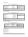
Power Management Setup
The Power Management Setup allows you to configure your system to most effectively save
energy saving while operating in a manner consistent with your own style of computer use.
Phoenix – AwardBIOS CMOS Setup Utility
Power Management Setup
ACPI function
C2 Disabled /Enabled
Power Management Option
HDD Power Down
Video Off Option
Video off Method
Modem Use IRQ
Soft-OFF by PWRBTN
Power On by PCI Card
Modem Ring Resume
APCI SDT Table
HPET Support
RTL Alarm Resume
*Date(of Month)
*Resume Time (hh:mm:ss)
Enabled
Disabled
User Define
Disabled
[suspend -> off]
V/H SyNC + BlANK
3
Instant off
Disabled
Disabled
Enabled
Enabled
Disabled
0
0:0:0
Item Help
Menu Level >
↑↓→← Move Enter:Select +/-/PU/PD:Value F10:Save ESC:Exit F1:General Help
F5:Previous Values
F6:Fail-safe Defaults
30
F7:Optimized Defaults
ACPI Function
This item allows you to Enabled/Disabled the Advanced Configuration and Power Management
(ACPI). The settings are Enabled and Disabled.
HDD Power Down (Disabled)
The IDE hard drive will spin down if it is not accessed within a specified length of time.Options
are from 1 Min to 15 Min and Disable.
Video Off Method
This determines the manner in which the monitor is blanked.
Initial display power management signaling.
DPMS (default)
This option only writes blanks to the video buffer.
Blank Screen
This selection will cause the system to turn off the vertical and
V/H SYNC+Blank
horizontal synchronization ports and write blanks to the video buffer.
.MODEM Use IRQ
If you want an incoming call on a modem to automatically resume the system from a
power-saving mode, use this item to specify the interrupt request line (IRQ) that is used by the
modem. You might have to connect the fax/modem to the motherboard Wake On Modem
connector for this feature to work.
Soft-Off by PWRBTN
Under ACPI (Advanced Configuration and Power management Interface) you can create a
software power down. In a software power down, the system can be resumed by Wake up Alarms.
This item lets you install a software power down that is controlled by the power Button on your
system. If the item is set to Instant-Off, then the power button causes a software power down. If
the item is set to Delay 4 Sec, then you have to hold the power button down for four seconds to
cause a software power down.
RTC Alarm Resume
When set to Enabled, additional fields become available and you can set the date (day of the
month), hour, minute and second to turn on your system. When set to 0 (zero) for the day of
the month, the alarm will power on your system every day at the specified time .
Date (of month)
You can choose which month the system will boot up. Set to 0, to boot every day.
Time (hh:mm:ss)
You can choose what hour, minute and second the system will boot up.
Note: If you have change the setting, you must let the system boot up until it goes to the
operating system, before this function will work.
Miscellaneous
Phoenix – AwardBIOS CMOS Setup Utility
Miscellaneous Control
Init Display First
Reset Configuration Data
Resource Controlled by
* IRQ Resource
PCI/VGA Palette Snoop
Assign IRQ for VGA
Assign IRQ for USB
PCI Latency Timer (CLK)
* PCI Express Relative Items
Maximum Payload Size
PCI Ex
Disabled
Auto [ESCD]
Press Enter
Disabled
Enabled
Enabled
[64]
Item Help
Menu Level >
4096
↑↓→← Move Enter:Select +/-/PU/PD:Value F10:Save ESC:Exit F1:General Help
F5:Previous Values
F6:Fail-safe Defaults
31
F7:Optimized Defaults
Reset Configuration Data
If you enable this item and restart the system, any Plug and Play configuration data stored in
the BIOS Setup is cleared from memory.
Init Display First
Use this item to specify whether your graphics adapter is installed in one of the PCI E slots or
is integrated on the motherboard. If a PCI E graphics card is installed, the onboard VGA will
be disabled.
PCI/VGA Palette Snoop
This item is designed to overcome problems that can be caused by some non-standard VGA
cards. This board includes a built-in VGA system that does not require palette snooping so
you must leave this item disabled.
Assign IRQ For USB
Names the interrupt request (IRQ) line assigned to the USB on your system. Activity ofthe
selected IRQ always awakens the system.
IRQ Resources
When resources are controlled manually, assign each system interrupt a type, depending on
the type of device using the interrupt.
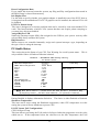
PC Health Status
This section shows the Status of you CPU, Fan, Warning for overall system status. This is
only available if there is Hardware Monitor onboard.
Phoenix – AwardBIOS CMOS Setup Utility
PC Health Status
Show H/W Health in Post
Shutdown Temperature
SMART FAN Configuration
Vcc3.3
Vcore
NBVCC
+5V
+12V
5VSB
VDIMM
CPU Temperature
System Temperature
CPUFAN
SYSFAN1
SYSFAN2
Enabled
Disabled
Press Enter
3.37v
1.27V
1.08V
5.24V
12.55V
5316V
1.96V
41°C
34°C
3625RPM
0 RPM
0 RPM
Item Help
Menu Level >
↑↓→← Move Enter:Select +/-/PU/PD:Value F10:Save ESC:Exit F1:General Help
F5:Previous Values
F6:Fail-safe Defaults
F7:Optimized Defaults
Show PC Health in Post
During Enabled, it displays information list below. The choice is either Enabled or Disabled
Shutdown Temperature
This item can let users setting the Shutdown temperature, when CPU temperature over this
setting the system will auto shutdown to protect CPU.
PS CPU Smart FAN Configurations
CPU Full-Speed Temp
This item allows you setting the FAN works in full speed when the temperature over the value
which out set. If the temperature below the value but over the Idle Temperature, the FAN
32
will works over 60% of full speed, and the higher temperature will gain higher FAN speed,
after over the temperature which this item setting, the FAN works in full speed.
CPU Idle Temp
This item allows you setting the FAN works in 60% of full speed, when the temperature
lower than the temperature which you setting.
CPU Temperature/ System Temperature / NBTemperature /SYSFAN1, FAN2
Speed/Vcore/ Vdd/3.3V/+5V/+12V/-12V/VBAT(V)/5VSB(V)
This will show the CPU/FAN/System voltage chart and FAN Speed.
Frequency /Voltge Control
oenix – AwardBIOS CMOS Setup Utility
Power User Overclock Settings
CPU/HT Reference Clk(MHz)
PCIE Reference clock
SB Reference clock
AMD CPU Ratio Control
Memory Clock Mode
*Memory Clock Value
CPU Vcore 7-shift
CPU Voltage at Next Boot
VDIMM Select
NB Voltage Setting
200
100
100
Auto
Auto
ddr667
Normal
Default
1.95v
Default
Item Help
CPU/HT Reference Clk
Min=190
Max=600
Key in a DEC number :[ ]
↑↓:Move ENTER:Accept ESC:Abort
Menu Level >
↑↓→← Move Enter:Select +/-/PU/PD:Value F10:Save ESC:Exit F1:General Help
F5:Previous Values
F6:Fail-safe Defaults
33
F7:Optimized Defaults
Phoenix – AwardBIOS CMOS Setup Utility
Power User Overclock Settings
CPU/HT Reference Clk(MHz)
PCIE Reference clock
SB Reference clock
AMD CPU Ratio Control
Memory Clock Mode
*Memory Clock Value
CPU Vcore 7-shift
CPU Voltage at Next Boot
VDIMM Select
NB Voltage Setting
200
100
100
Auto
Auto
ddr667
Normal
Default
1.95v
Default
CPU Vcore 7-Shift
Item Help
Normal... [ ]
+5% .... .[ ]
Menu Level >
+10% .... [ ]
+15%.... [ ]
+20%..... [ ]
+25%.... [ ]
+30%.... [ ]
+35%.... [ ]
↑↓:Move ENTER:Accept ESC:Abort
↑↓→← Move Enter:Select +/-/PU/PD:Value F10:Save ESC:Exit F1:General Help
F5:Previous Values
F6:Fail-safe Defaults
F7:Optimized Defaults
CPU Vcore
This item allows you select the CPU Vcore Voltage xx% more than the standard value, by
this function for the precise over-clocking for extra demanding of performance.
Phoenix – AwardBIOS CMOS Setup Utility
Power User Overclock Settings
CPU/HT Reference Clk(MHz)
PCIE Reference clock
SB Reference clock
AMD CPU Ratio Control
Memory Clock Mode
*Memory Clock Value
CPU Vcore 7-shift
CPU Voltage at Next Boot
VDIMM Select
NB Voltage Setting
200
100
100
Auto
Auto
ddr667
Normal
Default
1.95v
Default
NB Voltage Setting
Item Help
Default .....[ ]
1.15 v..... [ ]
Menu Level >
1.20 v ..... [ ]
↑↓:Move ENTER:Accept ESC:Abort
↑↓→← Move Enter:Select +/-/PU/PD:Value F10:Save ESC:Exit F1:General Help
F5:Previous Values
F6:Fail-safe Defaults
34
F7:Optimized Defaults
NB Voltage
This item allows you to select value of Voltage for North Bridge Chipset.
Phoenix – AwardBIOS CMOS Setup Utility
Power User Overclock Settings
CPU/HT Reference Clk(MHz)
PCIE Reference clock
SB Reference clock
AMD CPU Ratio Control
Memory Clock Mode
*Memory Clock Value
CPU Vcore 7-shift
CPU Voltage at Next Boot
VDIMM Select
NB Voltage Setting
200
100
100
Auto
Auto
ddr667
Normal
Default
1.95v
Default
VDIMM Select
Item Help
………
1.70v
Menu Level > [ ]
1.75v
[ ]
1.80v
[ ]
1.85v
[ ]
………………………………………………………………………..
2.55v
[
]
↑↓→← Move Enter:Select +/-/PU/PD:Value F10:Save ESC:Exit F1:General Help
F5:Previous Values
F6:Fail-safe Defaults
F7:Optimized Defaults
Phoenix – AwardBIOS CMOS Setup Utility
Power User Overclock Settings
CPU/HT Reference Clk(MHz)
PCIE Reference Clock
SB Reference Clock
AMD CPU Ratio Control
Memory Clock Mode
*Memory Clock Value
CPU Vcore 7-shift
CPU Voltage at Next Boot
VDIMM Select
NB Voltage Setting
[200]
100
100
Auto
Auto
ddr667
Normal
Default
1.95v
Default
Item Help
PCIE Reference Clock
Min = 90
Menu Level >
Max =250
Key in a DEC Number :
↑↓:Move ENTER:Accept ESC:Abort
↑↓→← Move Enter:Select +/-/PU/PD:Value F10:Save ESC:Exit F1:General Help
F5:Previous Values
F6:Fail-safe Defaults
F7:Optimized Defaults
Phoenix – AwardBIOS CMOS Setup Utility
Power User Overclock Settings
CPU/HT Reference Clk(MHz) 200
PCIE Reference clock
100
SB Reference clock
100
AMD CPU Ratio Control
Auto
Memory Clock Mode
Auto
*Memory Clock Value
ddr667
CPU Vcore 7-shift
Normal
CPU Voltage at Next Boot
Default
VDIMM Select
1.95v
NB Voltage Setting
Default
Item Help
CPU Voltage at Next Boot
Default .....[ ]
1.550v.....
]
Menu[ Level
>
1.525v ..... [ ]
1.500v ..... [ ]
. . . . . .
↑↓:Move ENTER:Accept ESC:Abort
↑↓→← Move Enter:Select +/-/PU/PD:Value F10:Save ESC:Exit F1:General Help
F5:Previous Values
F6:Fail-safe Defaults
35
F7:Optimized Defaults
Phoenix – AwardBIOS CMOS Setup Utility
Power User Overclock Settings
CPU/HT Reference Clk(MHz)
PCIE Reference clock
SB Reference clock
AMD CPU Ratio Control
Memory Clock Mode
*Memory Clock Value
CPU Vcore 7-shift
CPU Voltage at Next Boot
VDIMM Select
NB Voltage Setting
200
100
100
Auto
Auto
ddr667
Normal
Default
1.95v
Default
AMD CPU Ratio Control Item Help
Auto ...
[ ]
X4..
... [ ]
Menu Level >
X4.5..... [ ]
X5..... [ ]
X5.5..... [ ]
X6....
[ ]
X6.5... . [ ]
…..
↑↓:Move ENTER:Accept ESC:Abort
↑↓→← Move Enter:Select +/-/PU/PD:Value F10:Save ESC:Exit F1:General Help
F5:Previous Values
F6:Fail-safe Defaults
F7:Optimized Defaults
Phoenix – AwardBIOS CMOS Setup Utility
Power User Overclock Settings
CPU/HT Reference Clk(MHz)
PCIE Reference clock
SB Reference clock
AMD CPU Ratio Control
Memory Clock Mode
*Memory Clock Value
CPU Vcore 7-shift
CPU Voltage at Next Boot
VDIMM Select
NB Voltage Setting
SB Reference Clock
200
100
100
Auto
Auto
ddr667
Normal
Default
1.95v
Default
Item Help
Min = 90
Max =150
Key in aMenu
DEC Level
Number> :
↑↓:Move ENTER:Accept ESC:Abort
↑↓→← Move Enter:Select +/-/PU/PD:Value F10:Save ESC:Exit F1:General Help
F5:Previous Values
F6:Fail-safe Defaults
36
F7:Optimized Defaults
CPU Thermal –throttling
Phoenix – AwardBIOS CMOS Setup Utility
CPU Themal-Throttling
CPU Thermal –Throttling
*CPU TThermal-Throttling
Disabled
70
Item Help
Menu
Thermal Throttling Temp
Min=40
Max=90
Key in a DEC number
↑↓:Move ENTER:Accept
ESC:Abort
Level >>
↑↓→← Move Enter:Select +/-/PU/PD:Value F10:Save ESC:Exit F1:General Help
F5:Previous Values
F6:Fail-safe Defaults
F7:Optimized Defaults
Load Fail-Safe Defaults
Load Fail-Safe Defaults
When you press <Enter> on this item, you get a confirmation dialog box with a message similar
to:
Load Fail-Safe Defaults (Y/N)? N
Pressing <Y> loads the default values that are factory settings for stable performance system
operations.
Load Optimized Defaults
Load Optimized Defaults
When you press <Enter> on this item, you get a confirmation dialog box with a message similar
to:
Load Optimized Defaults (Y/N)? N
Pressing <Y> loads the default values that are factory settings for optimal performance system
operations.
37
Password Settings
You can set either supervisor or user password, or both of them. The differences are:
Supervisor password:
Can enter and change the options of the setup menus.
User password:
Can only enter but do not have the right to change the options of the
setup menus. When you select this function, the following message
will appear at the center of the screen to assist you in creating a
password.
ENTER PASSWORD:
Type the password, up to eight characters in length, and press <Enter>. The password typed
now will clear any previously entered password from CMOS memory. You will be asked to
confirm the password. Type the password again and press <Enter>. You may also press <Esc>
to abort the selection and not enter a password.
To disable a password, just press <Enter> when you are prompted to enter the password. A
message will confirm that the password will be disabled. Once the password is disabled, the
system will boot and you can enter Setup freely.
PASSWORD DISABLED.
When a password has been enabled, you will be prompted to enter it every time you try to enter
Setup. This prevents an unauthorized person from changing any part of your system
configuration.
Additionally, when a password is enabled, you can also require the BIOS to request a password
every time your system is rebooted. This would prevent unauthorized use of your computer.
You determine when the password is required within the BIOS Features Setup Menu and its
Security option. If the Security option is set to “System”, the password will be required both at
boot and at entry to Setup. If set to “Setup”, prompting only occurs when trying to enter Setup.
38
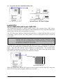
DRIVER & FREE PROGRAM INSTALLATION
Check your package and there is A MAGIC INSTALL CD included. This CD consists of all
DRIVERS you need and some free application programs and utility programs. In addition, this CD
also include an auto detect software which can tell you which hardware is installed, and which
DRIVERS needed so that your system can function properly. We call this auto detect software
MAGIC INSTALL.
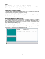
Driver Installation supports WINDOWS 9X/NT/2K/XP
Insert CD into your CD-ROM drive and the MAGIC INSTALL Menu should appear as below.
If the menu does not appear, double-click MY COMPUTER / double-click CD-ROM drive or
click START / click RUN / type X:\SETUP.EXE (assuming X is your CD-ROM drive).
From Driver Installation MENU you may take 8 selections:
1. ATI
install ATI integrated driver pack
2. SOUND
install ALC883 HD Audio driver
3. LAN
install Realtek LAN Controller driver
4. USB2.0
install USB 2.0 driver
5. RAID
install RAID SATA driver and utility
6. PC-CILLIN
install PC-CILLIN 2007 anti-virus program
7. PC-HEALTH
install MyGuard Hardware Monitor Utility
39
8. BROWSE CD
9. EXIT
to browse the contents of the CD
to exit from MAGIC INSTALL menu
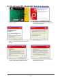
Install ATI Intergrated Driver Pack
1. Click ATI in the MAGIC INSTALL MENU
appears.
2. Click Next when ATI software driver pack
appears.
3. Click “Yes” to accept the license agreement
and start installation..
*
4. Click Finish to restart your computer
The path of the file is X:\ATI \DRIVER\SETUP.EXE
Install ALC883 HD Audio Driver
1. Click SOUND when MAGIC INSTALL
MENU appears
2. Click Next when Realtek High Definition
Audio driver windows appear
40
3.
Click FINISH and restart your computer
4.
Manual Sound Effect Setting
5.
Drivers and mixer.
6.
Audio input and output settings .
8.
3D Audio
7. Microphone effect.
NOTE: Please upgrade your Windows XP to Service Pack 1 / Windows 2000 to Service Pack 4
or later before you the HD Audio CODEC driver.
41
Install Realtek LAN Controller Driver
1. Click LAN when Magic Install Menu appear
2. Click Install to install REALTEK LAN and Fast
Ethernet NIC Driver
3. To click “yes” to accept the license agreement 4.Click install
5. Installing proseces
6.After driver installation completed, click finish
42
Install ATI USB2.0 DRIVER
Windows 2000 OS
Please install Windows 2000 service pack 4 or later .
Windows XP OS
Please install Windows XP service pack 1 or later .
Install RAID SATA Driver and Utility
1 Click RAIDDisk when MAGIC INSTALL
MENU appears
2.
43
Install RAID Disk.
PC-CILLIN Install PC-CILLIN 2007 Anti-virus program
1.
Click PC-CILLIN when MAGIC INSTALL
MENU appears
2.
3.
This is license agreement, select "I accept the 4.
terms in the licence agreement" and Click
NEXT
The scanning process
5.
Click Next after you select the features you
want to install and the folder to install it
6.Click Install after you select to install the
optional online services.
44
Please select “Install program” when the
"Trend Micro internet security" install shield
wizard windows appears
7. copying new files
8. click “automatically restart your computer
now ”and Finish to activate this function.
Install MyGuard Hardware monitor Utility
1. Click PC-health when MAGIC INSTALL
MENU appears
2. Click Next on My Guard Install Shield Wizard
Window
3. Click Install to begin the installation.
4. Click Finish to complete the installation.
45
AMD Platform RAID Function Installation
Step 1.
Please get into the location: BIOS setup \ Integrated Peripherals \ Onchip IDE function \
Onchip SATA Type ,choose RAID to enable the RAID function and choose the RAID hard
drive channel.
Phoenix – AwardBIOS CMOS Setup Utility
RAID Configuration
RAID Enable
Enabled
IDE Primary Master RAID
Disabled
IDE Primary Slave
RAID
Disabled
IDE Secondary Master RAID
Disabled
IDE Secondary Slave RAID
Disabled
SATA Channel 1
Enabled
RAID
SATA Channel 2
Enabled
RAID
SATA Channel 3
Enabled
RAID
SATA Channel 4
Enabled
RAID
Item Help
Menu Level >>
↑↓→← Move Enter:Select +/-/PU/PD:Value F10:Save ESC:Exit F1:General Help
F5:Previous Values F6:Optimized Defaults
F7:Standard Defaults
Step 2.
After the System boot up in the second page , you can find the NVIDIA RAID IDE ROM
BIOS windows appear. It will ask you to “Press F10 to enter RAID setup utility …“ ?
Please press “F10” key to RAID utility now , then you can select the RAID functions on your
own with the optional RAID functions as below,
1. Mirroring 2. Striping 3. Striping Mirroring 4. Spanning
Array 1 : NVIDIA MIRROR 74.50G
- Array Detail RAID Mode : Mirroring
Striping Width : 1
Striping Block: 64K
Adapt Channel M/S
1
0
WD800JB-75JMA0
Capacity
Master
0
WDC
Master
0
WDC
75.50GB
1
WD800JB-75JMA0
Index Disk Model Name
0
75.50GB
[R] Rebuild
[D] Delete
[C] Clear Disk
46
[ENTER]
Return
Step 3.
Making RAID driver diskette before Install WindowsXP/2000
Before you install the Windows XP or Windows 2000, you will need to make a RAID driver
diskette before you start to install the Operating System.
How to make a RAID driver diskette?
1: Insert the diskette which is being formatted in floppy drive on a system which can start OS.
2: After booting OS insert the bundle CD in your CD-ROM
3: Copy all the files from \NF-orce4\RAIDDisk to floppy diskette
Once you have the SATA driver diskette ready, you may start to install Windows XP or
Windows 2000 on your System.
Installation of Windows XP/ Windows 2000
For installation of Windows XP or Windows 2000, please insert Windows XP or Windows
2000 CD into the CD-ROM drive. Then remove the floppy diskette, and boot the system. At
the very beginning, you will see the message at the bottom of screen, “Press F6 if you need to
install a third party SCSI or RAID driver….”
At this moment, please press <F6> key and follow the instructions of Windows XP or
Windows 2000 for the proper installation.
Execute Start Æ programs Æ ATI corporation Æ RAID manager , you can view RAID
function status or rebuild RAID function from Windows OS
47
Pro Magic Plus Function Introduction
What’s Pro Magic Plus?
Tired with reinstall OS each time when it doesn’t work? Does your computer often crash
down or unable to work after installed new software? Have you had great loses and troubles
because of computer problems? Still using time-consuming backup software that occupies
lots of HD space?
Pro Magic Plus- an instant system recovery software tailored to solve these problems for you.
It combines various application tools (e.g. anti-virus, backup software, uninstall software,
multi-boot software) to satisfy your needs of all sorts of system protections.
What functions does Pro Magic Plus have?
1.
Instant System Restoration – Regardless of mis-operation or system crash, install Pro
Magic Plus beforehand would allow you to instantly restore your system back by simply
reboot your computer.
2.
Easy-to-use – Auto installation from CD ROM; Supports Mouse
3.
System Uninstall – Pro Magic provides a protection mode, which allows user to freely
test any software. If user does not want to keep the software, just reboot the computer
to restore back to the previous state, and Pro Magic will remove it completely from you
computer.
4.
Password Security – Pro Magic provides double password protection, including user
password for entering each OS and manager password for managing ‘Pro Magic’, which
can effectively prevent others from using your computer without permission or data from
being stolen. (disable item for OEM version)
5.
Complete Protection – Pro Magic not only protects the system disk, but also can
protect your data disk, and does not require to reboot when backup or restore data disk.
6.
Multipoint Save/Restore – You can backup your system whenever you need and
restore them back to anytime you wish, 1 hour, 1 day or 1 month ago. Restore points
are unlimited. (disable item for OEM version)
7.
Data Disk Protection – Pro Magic Plus now comes with data disk protection, provides
complete protection for your computer! (disable item for OEM version)
8.
You can choose to change the default path of ‘My Document’, ‘My Favorite’ and
‘Outlook Express’, so that when you are restoring the system, data in these folders will
not be restored as well. (This is optional, you can leave it as it is).
48
NOTE: Functions of each version will differ from each other, and will be based on the function
descriptions of each version.
System Requirements
◇
◇
◇
◇
◇
◇
First OS must be Windows 98 SE/ME/2000/XP
Support Only Windows OS (No Linux)
Windows server OS and Windows NT not supported
Minimum of Intel 486 or above, 16MB of memory or above
Minimum of 500MB free/usable space or above
Support for SCSI & SATA Hard disk
Pro Magic Plus only supports SCSI hard disk with Windows 2000 or OS above
Notice Before Installation
1. Before install Pro Magic Plus, turn off all anti-virus software. (Include BIOS anti-virus
function)
2. Pro Magic Plus does not support multiple PRI partitions.
partitions, please repartition your HD before installation.
If you have multiple PRI
3. If your HDD is not fully partitioned (with un-partitioned/unused space at end of HDD),
please repartition the HDD before install Pro Magic Plus.
49
USEFUL HELP
HOW TO UPDATE BIOS
Before updating the BIOS, users have to “Disable” the “Flash Part Write Protect” selection
in “Miscellaneous Control” of BIOS SETUP. Otherwise the system the will not allow you
to upgrade BIOS by Award Flash Utility.
STEP 1. Prepare a boot disc. (you may make one by click START click RUN type SYS A:
click OK)
STEP 2. Copy utility program to your boot disc. You may copy from DRIVER CD
X:\FLASH\AWDFLASH.EXE or download from our web site.
STEP 3. Download and make a copy of the latest BIOS for 770 SERIES motherboard series
from the web site to your boot disc.
STEP 4. Insert your boot disc into A:,
start the computer, type “Awdflash A:\xxxxxx.BIN /SN/PY/CC/R”
xxxxxx.BIN is the file name of latest BIOS
SN
means
don’t save existing BIOS data
PY
means
renew existing BIOS data
CC
means
clear existing CMOS data
R
means
restart computer
STEP 5. Push ENTER to update and flash the BIOS, then the system will restart
automatically.
Trouble Shooting
Problem
Solution
No power to the system to the all power light
don’t illuminate, fan inside power supply doesn’t
turn on.
System inoperative. Keyboard lights are on ,
power indicator lights are lit, and hard drive is
spinning.
System doesn’t boot from hard disk drive, can be
booted from optical drive.
1. Make sure power cable is security plugged in.
2. Replace cable. 3. Contact technical support.
System only boots from optical drive .Hard disk
can be read and applications can be used but
booting from hard disk is impossible.
Screen message says “Invalid Configuration” or
“CMOS Failure”
Can not boot system after installing second hard
drive.
1. Back up date and applications files. 2.
Reformat the hard drive. Reinstall applications
and date using backup disks.
Review system ‘s equipment .Make sure correct
information on is in setup.
1. Set master /slave jumpers correctly. 2. Run
SETUP program and select correct drive types.
Call the drive manufacture for compatibility with
other drives.
Using ever pressure on both ends of the DIMM ,
press down firmly until the module snaps into
places.
1. Check cable running from disk to disk
controller board. .Make sure both ends are
securely plugged in, check the drive type in the
standard CMOS setup. 2. Backing up the hard
drive is extremely important .All hard disks are
capable of breaking down at any time.
50
Glossary
Chipset (or core logic) - two or more integrated circuits which control the interfaces between
the system processor, RAM, I/O devises, and adapter cards.
Processor slot/socket - the slot or socket used to mount the system processor on the
motherboard.
Slot (PCI-E, PCI, RAM) - the slots used to mount adapter cards and system RAM.
PCI - Peripheral Component Interconnect - a high speed interface for video cards, sound
cards, network interface cards, and modems; runs at 33MHz.
PCI Express- Peripheral Component Interconnect Express- a high speed interface for video
cards, sound cards, network interface cards, and modems.
Serial Port - a low speed interface typically used for mouse and external modems.
Parallel Port - a low speed interface typically used for printers.
PS/2 - a low speed interface used for mouse and keyboards.
USB - Universal Serial Bus - a medium speed interface typically used for mouse, keyboards,
scanners, and some digital cameras.
Sound (interface) - the interface between the sound card or integrated sound connectors and
speakers, MIC, game controllers, and MIDI sound devices.
LAN (interface) - Local Area Network - the interface to your local area network.
BIOS (Basic Input/Output System) - the program logic used to boot up a computer and
establish the relationship between the various components.
Driver - software, which defines the characteristics of a device for use by another device or
other software.
Processor - the "central processing unit" (CPU); the principal integrated circuit used for
doing the "computing" in "personal computer"
Front Side Bus Frequency - the working frequency of the motherboard, which is generated
by the clock generator for CPU, DRAM and PCI BUS.
CPU L2 Cache - the flash memory inside the CPU, normal it depend on CPU type.
51