1
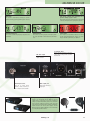
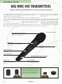
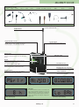
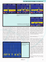
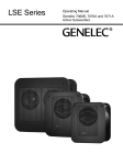
AKG WMS SR 400 UHF
AKG WMS 400 RECEIVER
THE FIRST STEP TO PROFESSIONAL MULTICHANNEL TECHNOLOGY
The SR 400 diversity receiver is an optimal System, you can set up even complex wireless
solution if you need a reasonably-priced, high- systems using antenna splitters, power supply
units and a whole range of high-performance
performance multichannel system.
external antennas.
Based on the technology and experience of the
revolutionary WMS 4000 wireless system, the It has never been easier to set up a professional
SR 400 offers countless features that make wireless system in this price bracket than with
the WMS 400 system. In Auto Setup mode, the
setup and operation easier than ever before.
receiver automatically scans the RF environWith simultaneous operation of up to 12 chan- ment in the available frequency bands, finds an
nels on each frequency band, you can be cer- interference-free channel, and is able to transtain of smooth operation even in tricky situa- mit this preset to the associated transmitter by
tions in critical RF environments. Thanks to its infrared. This makes it possible to set up a mulcompatibility with the professional WMS 4000 tichannel system in just a couple of minutes.
Increased operational reliability and user convenience are ensured especially by the rehearsal
function (complete RF testing of all components), clear display of all parameters on a programmable display, an easily visible warning
signal with two-color display backlighting, and a
low-battery warning on the receiver.
Housed in a rugged half-rack metal case with a
host of innovative features, the SR 400 receiver offers all the benefits to make this a top-quality wireless system for both the upcoming star
and the price-conscious professional.
Backlit LC display
Gives you a function check at a glance, with two-color
backlighting (red/green).
Status LEDs
Provide detailed information about the most
important system parameters, such as audio
level, diversity status, RF level, etc.
SR 400 Receiver
On/Off switch
Recessed level control
Allows you to adjust the output
level, recessed to prevent accidental readjustment.
Infrared interface for transmitter programming
Fast and reliable transmission of frequency settings to
prevent misprogramming.
Display Details
➊
Menu buttons
Facilitate easy programming.
➑
➊ 7-level audio bargraph display
Display Details
➎ Special functions: receiver name, status display,
squelch threshold, system info, etc.
➋ Frequency setup menu with three operating
modes: Auto Group, Auto Channel, Preset
➏ Lock mode
➌ Infrared transmission mode
➐ Squelch threshold adjustment mode
➍ Rehearsal function: Rapid check of RF & audio
signal quality
➑ 7-level RF bargraph display and diversity LEDs
➋
➌
➍
➎
* The maximum number of channels may vary according to local frequency plans.
28
Metal case
Half-rack width for convenient rack installation.
www.akg.com
➏
➐
AKG WMS SR 400 UHF
Auto setup
The receiver is automatically searching for clean frequencies, making system programming quick and easy.
Infrared transmission
The receiver is downloading frequency setup data to the
transmitter.
Each Preset contains legal frequencies for a
specific country, region, or state
Integrated frequency management database with country
coded sets of frequencies for easy frequency selection.
Rehearsal mode
The receiver is recording dropouts and related parameters as the transmitter is moved about the performance
area.
XLR audio output
Professional balanced XLR
output connector.
Antenna input socket
Allow you to connect plug-in
antennas, remote antennas, or
even a complex antenna network.
System status
If, for instance, the transmitter batteries are running
low, the display backlighting will change to red, reminding you that the system needs your attention.
Lockable DC input
Ensures reliable connection to the power
supply, with a lock to prevent accidental
disconnection.
Audio output jack
Professional unbalanced
output jack.
Range of accessories for complex applications
Thanks to its compatibility with the WMS 4000 wireless
system, there is a wide range of accessories available for
setting up complex multichannel systems. These include the
PS 4000 antenna splitter, the PSU 4000 power supply unit,
active and passive antennas with a variety of polar patterns,
antenna boosters and remote power supplies, and the
HPA 40 headphone amplifier. WMS 4000 Series transmitters
also work perfectly with an SR 400.
www.akg.com
29
AKG WMS HT 400 UHF
AKG WMS 400 TRANSMITTERS
HANDHELD AND BODYPACK TRANSMITTERS FOR EVERY CONCEIVABLE APPLICATION
remaining battery life, low battery warning, microphone element. A noiseless On/Mute/
Off switch and status LED provide additional
and current transmission mode.
user convenience.
Once you have set a frequency on the receiver, an infrared transmission link will feed The PT 400 bodypack transmitter has a rugthe related data to the assigned transmitter ged metal case with a mini XLR socket that
within seconds, making the setting up of allows you to connect a wide variety of microphones and instruments. It also has a jack for
large multichannel systems child's play.
connecting an external mute switch – a parAn LC display provides information at a
glance about important parameters such as The HT 400 handheld transmitter is avail- ticularly useful feature when the transmitter
frequency/Preset name (country code), able with either a dynamic or a condenser is inaccessible.
The HT 400 handheld and the PT 400 bodypack are high-performance, compact wireless
transmitters that can be used for every conceivable application. Many innovative features not only ensure greater reliability of
operation, but also provide extremely convenient operation.
HT 400 Handheld transmitter
Extremely rugged spring steel mesh grill
Protects the microphone capsule underneath in
tough stage acts and live performances.
Infrared sensor
Makes child’s play of transmitter programming by
downloading frequency and gain settings from the
receiver via infrared.
Display
Shows the selected frequency/ preset and remaining
battery life.
On-Mute/Program-Off switch
A recessed mode switch prevents accidental mode switching.
Soft-touch enamel finish
Adds to handling noise rejection.
Charging contacts
Convenient plug-in charging on the CU 400
charger is environmentally friendly and
saves money.
PPC 1000 Polar Pattern Converter
30
Interchangeable, color code strips you can write on
For convenient transmitter identification on multichannel
systems.
Battery compartment
The transmitter can be powered by a single
AA size dry or rechargeable battery.
PPC 1000 and PB 1000 for the C 900
You can quickly change the polar pattern of the C 900 from cardioid to hypercardioid by attaching the supplied PPC 1000 Polar
Pattern Converter (left) to the capsule. Also supplied with the C
900, the PB 1000 Presence Boost Adapter (right) provides a 3
to 5 dB presence rise between 5 kHz and 9 kHz for better intelligibility and a more sparkling instrument sound.
www.akg.com
PB 1000 Presence Boost Adapter
AKG WMS PT 400 UHF
Microphones for PT 400
C 411 L
C 416 L
C 417 L
C 419 L
C 420 L
C 444 L
CK 77 WR L CK 77 WR L/P CK 97-C/L
MKG L
CK 55 L
C 477 WR L
For hints on how to use MicroMic Series products refer to pages 70 and 71.
PT 400 Portable transmitter
Flexible Antenna
Maximum transmission reliability.
Rugged mini XLR connector
Professional 3-pin mini XLR input for connecting
MicroMic Series or other head-worn microphones,
lavalier microphones, or instrument cables from AKG.
Soft-touch finish
Soft-touch enamel reduces handling noise.
Infrared Sensor
Setting up the transmitter is incredibly easy as frequency and
gain data is downloaded from the receiver via infrared transmission.
Input gain control
Sets the gain of the audio input stage.
Display
Indicates the selected frequency or preset as well as the
remaining battery capacity in hours.
Detachable belt clip
0,1 ” jack for external mute switch
An external mute switch allows the user to mute the signal even if the transmitter is hidden beneath clothes.
Interchangeable color code labels
For identifying multichannel system transmitters.
Charging contacts
Convenient plug-in charging on the CU 400 charger is
cost efficient and friendly to the environment.
Frequency is being downloaded from the receiver
Battery compartment
The transmitter can be powered by a single AA
size dry or rechargeable battery.
Frequency preset
Frequency in MHz
LCD display
The LCD on the HT/PT 400 provides a clear readout of the
most important transmitter parameters. As soon as the
battery capacity drops to a critical level, a warning will
appear in the display. Simultaneously, the receiver will display the same warning and change the display backlighting to red.
Battery status display
Low battery capacity warning
www.akg.com
31
AKG WMS CU 400
THE AKG WMS 400 SERIES CHARGER
THE USER FRIENDLY QUICK CHARGER
time, it is still a good idea to use fresh dry or The CU 400 puts an end to this kind of hassle.
It can charge two batteries simultaneously to
fully charged rechargeable batteries.
full capacity within less than two hours, and
However, the setup phase and the soundcheck there is no risk of overcharging the batteries.
already use up some of each transmitter battery's capacity, so the batteries need to be top- And what's more, you can leave the batteries
ped up before the show. Obviously, there is not inside the transmitters. The transmitters and
Although the battery status indicators and war- enough time to use a conventional charger, let charger use integrated charging contacts so all
ning lights on the WMS 400 transmitters and alone take the transmitters apart to get at the you have to do is plug the transmitters into the
CU 400 and remove them after charging.
receiver alert you to a dying battery ahead of batteries inside their compartments.
Any wireless microphone system depends on
sufficiently charged batteries in all the transmitters. There is nothing more embarrassing
than a transmitter running out of juice in the
middle of the show, or a voice fading as the
transmitter battery dies.
2 universal charging slots
Accommodate HT 400 and PT 400 transmitters.
CU 400 Charging unit
Locking DC jack
Input jack for a local or central power supply
(e.g., PSU 4000).
Charging status LEDs
Integrated charging contacts for direct charging
Both the HT 400 and the PT 400 provide integrated bottom
panel charging contacts. To get the batteries fully charged in
less than two hours, just plug the transmitters into the CU 400.
A single CU 400 can charge two transmitters simultaneously,
making it easy to restore even a large number of transmitters
to maximum performance within a short time.
32
www.akg.com
AKG WMS 400 ACCESSORIES
SRA 1 – Passive wideband dirctional antenna
• For indoor and outdoor use, specifically for setting up
long-range radio links
• For use with short antenna cables
SRA 2B – Active wideband dirctional antenna
• For indoor and outdoor use, in particular for setting up
long radio links
• Integrated high-performance antenna booster for use of
long antenna cables
• Remote powering option, status LED
• Rugged water-resistant case with BNC output
RA 4000 B
– Omnidirectional wideband booster antenna
• For indoor and outdoor use, in particular for near-field
antenna setups with no preferred direction
• Integrated high-performance antenna booster for use of
long antenna cables
• Remote powering option, status LED
• Rugged water-resistant case with BNC output
AB 4000 – Antenna booster
• Ultralinear antenna booster with water-resistant case
• BNC or N inputs and outputs, DC input, status LED
• DIP switch for gain adjust
HT 4000
• Wideband UHF handheld transmitter with interchangeable microphone elements and metal die-cast body
• Preprogrammed factory presets
• Up to 24 intermodulation-free frequency groups in each
30 MHz wide UHF band
• Up to 15 hours continuous operation on 2 AA size alkaline
batteries or a minimum of 12 hours on optional BP 4000
battery pack
PT 4000
• UHF bodypack transmitter with magnesium body
• 1200 selectable frequencies in 30 MHz band
• Backlit display and jog switch operation
• Up to 50 mW (ERP) output for reliable transmission
• Optional remote mute switch
• Operates for up to 15 hours on AA batteries, 12 hours on
optional BP 4000 battery pack, and displays remaining
battery life
PS 4000
• Expandable modular antenna splitter with metal case
• 220 MHz bandwidth for use with all WMS 4000 channels
• Adjustable cable length compensation
• For multi-room installation of antenna systems
PSU 4000 Central power supply unit
• Powers up to 12 SR 4000 receivers plus antennas via
3 PS 4000 antenna splitters, or three CU 4000 charging
units
• Also powers the HPA 4000 headphone amplifier or
HUB 4000 network concentrator
HPA 4000 Headphone amplifier
• For connecting up to 8 SR 4000 receivers
www.akg.com
33
AKG WMS MULTICHANNEL TECHNOLOGY
SETTING UP MULTICHANNEL SYSTEMS
HOW TO DEAL WITH INTERMODULATION AND KEEP YOUR FREQUENCIES STRAIGHT
Whenever two or more signals are transmitted by a non-ideal system, undesired intermodulation products will be created, causing distortions (see also WMS 400, p. 31).
An ideal system would deliver an output
signal that is identical to the input signal
over the whole frequency range even at larger amplitudes, and no problems would
arise.
In practice, however, ideal systems do not
exist, as transistors in particular have only
a relatively narrow linear gain range. This is
why the transmission of several signals via
nonlinear systems, such as transmitters
and receivers, will result in unwanted arti-
facts generated by intermodulation. These Whenever the frequency of the desired sigintermodulation products have to be dealt nal coincides with that of an intermodulation product the signal will be distorted.
with somehow in practice.
Moreover, the intermodulation product may
The order of intermodulation products activate the receiver's squelch function if
depends on the nonlinearity of the system the amplitude of the intermodulation freresponse curve; the amplitudes of intermo- quencies exceeds the squelch threshold.
dulation products will always grow in proportion to the product of the mathematical Obviously, the effective impact of intermopowers of the fundamental signals genera- dulation distortion also depends on the
ting a given intermodulation product. In distance between transmitter and receiving
reality, third-order intermodulation pro- antenna. In the case of wireless microphoducts tend to be particularly troublesome nes transmitting on an intermodulation frebecause they rise much more rapidly than quency, the desired signal is often ruined by
the fundamental signal, thus turning into intermodulation distortion if you move the
transmitter too far away from the receiver.
real, i.e., audible noise.
Ideal and real gain curves
of ideal and real amplifiers
High audio input levels may overload the amplifier, so the
peaks of the amplified signal are clipped as a result of
saturation. The compression characteristic may be described by a polynomial (i.e., the sum of multiples of powers
of a variable X). This polynomial includes all powers, with
the odd powers (3, 5, 7, ...) responsible for intermodulation
in multichannel systems. Because of its high coefficient,
the third power term is especially important which is why
third-order intermodulation products are dominant. The
reciprocal value of the third-order coefficient defines the
IP 3 Intercept (see below), which is the most important
parameter for the intermodulation resistance of an RF
amplifier. A smaller third-order coefficient of the transmission polynomial means a higher IP 3, which implies
greater linearity of the RF amplifier and thus better resistance to intermodulation distortion.
IP 3 Intercept
The Intercept marks the intersection of the theoretical
linear transfer curve for the wanted signal’s amplifier response curve and the theoretical linear transfer curve for
the third-order intermodulation product. It is never actually reached because the amplifier will compress the wanted
signal before it reaches the IP 3 Intercept level.
The higher the Intercept of a radio transmission system,
the lower the IM risk, and the more channels may be used
within a given frequency band.
34
www.akg.com
AKG WMS MULTICHANNEL TECHNOLOGY
Microphone A carrier frequency
Spectrum analyzer trace
Intermodulation of carrier frequencies A and B
The trace clearly shows that third-order intermodulation
products are only 38 dB lower in level than the carrier
frequencies.
Microphone B carrier frequency
Spectrum analyzer trace
Intermodulation trace on a spectrum analyzer display
Third-order intermodulation products from three carrier
frequencies.
The received signal level declines in proportion to the square of the distance between transmitter and receiver, and the
intermodulation level produced in the
receiver declines in proportion to the third
power of the received signal level. This
implies that intermodulation declines exponentially, in proportion to the sixth power of
the distance between transmitter and receiver. If the distance is longer than 66 feet
(20 m), receiver intermodulation is drowned out by noise. What remains is another
important type of intermodulation distortion that has not yet been mentioned: transmitter intermodulation. In this case, the
intermodulation products are not generated
in the receiver, but in the transmitters, and
are radiated by them along with the desired
carrier frequencies. This will only happen,
however, if there is enough crosstalk of carrier frequencies between two neighboring
transmitters that intermodulate with each
other. In this case, the antenna of one
transmitter receives the carrier signal of a
neighboring transmitter. If this signal
makes it into the non-linear output stage of
the transmitter, the first harmonic of the
desired signal will transform it into a signal
whose frequency is indistinguishable from
the receiver intermodulation. The same
happens in the other transmitter that will
generate a mirror-image intermodulation
product. Curiously, a love duet close to the
receiving antennas may lead to intermodulation distortion caused by the nonlinear
receiver. If the two singers move away, the
Intermodulation trace on a
spectrum analyzer display
Intermodulation products from 2
carrier frequencies, 3rd-order IMD
and 5th-order IMD.
intermodulation remains unchanged, but is
now produced in the transmitters. In large
multichannel systems, reducing the RF
output of the transmitters is a way to bring
down transmitter intermodulation by minimizing the nonlinear response of the transmitter's output stage. The RF output of
WMS 4000 transmitters, for example, can
be reduced from 50 mW to 10 mW (ERP –
Equivalent Radiated Power).
Here are some hints on how to minimize
receiver intermodulation:
Always lay out the antenna system so as to
ensure reliable transmission from every
point on the stage. Moreover, be sure to use
only the types of cables recommended in
the user’s manual. The distance between
transmitters and active antennas should be
at least 15 feet (5 m) (see also Antenna
Position Check Applet on p. 45).
Increasing the input attenuation of the
antenna system helps, as does reducing the
transmitter RF output to 10 mW. The latter
has proved particularly useful for hand-held
transmitters in situations where range is
not an important consideration; generally,
the RF output level used should always be
just high enough to ensure adequate transmission. Systems with a higher transmitter
RF output (ERP) are more prone to intermodulation problems, but this is compensated for by their better resistance to electrosmog.
When multichannel systems are used on
Broadway, for instance, only the strongest
will survive.
www.akg.com
35
AKG WMS MULTICHANNEL TECHNOLOGY
SETTING UP MULTICHANNEL SYSTEMS
HOW TO DEAL WITH INTERMODULATION AND KEEP YOUR FREQUENCIES STRAIGHT
Frequency Management: a good idea for any multichannel system
One way to run a multichannel system would be to hire an RF engineer with a university degree for doing nothing but the number
crunching required for finding clean frequencies and keeping an eye on all the batteries in the system. Unfortunately, it is not
easy to find someone with this kind of knowledge, and then these experts are extremely busy and expensive.
Don't worry, there is an easier way. WMS Series wireless systems from AKG provide both an integrated Frequency Management
System and clear battery status readouts to remove the hassle from setting up and operating a multichannel system and save
time and money.
Calculation of intermodulation products
fIM = | m1f1 + m2f2 + m3f3 + m4f4 + … |
mv = 0, ±1, ±2, ±3, ±4, …
The order of IM products depends on the non-linearity of the transfer characteristic.
fIM = | 2 f1 ± f2 | ,
fIM = | f1 ± f2 ± f3 |
3rd order
Derivation of 3rd order intermodulation products
(cosω1t + cosω2t + cosω3t)3 =
(
+ 3
+ 3
+ 3
e jω t + e -jω t
1
1
2
(
(
(
e jω t + e -jω t
1
1
2
e jω t + e -jω t
2
2
2
e jω t + e -jω t
3
3
2
2
)
2
)
2
)
2
2
2
e jω t + e -jω t
2
2
+3
2
e jω t + e -jω t
1
1
+3
2
e jω t + e -jω t
1
1
+3
2
(
(
(
2
1
2
e jω t + e -jω t
2
2
2
e jω t + e -jω t
3
3
2
2
2
2
www.akg.com
3
3
1
e jω t + e -jω t
2
2
e jω t + e -jω t
e jω t + e -jω t
e jω t + e -jω t
1
Dual-tone products are obtained from lines 1 through 4,
e.g., | fIM = 2f1 - f2 |
Three-tone products are obtained from line 5,
e.g., | fIM = f1 + f2 - f3|
36
3
)+(
e jω t + e -jω t
1
+ 6
e jω t + e -jω t
3
)+(
3
3
2
)
2
)
2
)
3
)
e jω t + e -jω t
3
3
2
e jω t + e -jω t
3
3
2
e jω t + e -jω t
2
2
2
AKG WMS MULTICHANNEL TECHNOLOGY
The far-near difference
Unlike a hardwire microphone, even the best wireless
system is susceptible to dropouts because the relative
positions of persons and objects within the coverage area
will change constantly during an event. At any moment,
shadow loss and signal cancellation may coincide with
intermodulation and sideband noise in such a way as to
cause a dropout. The specified dropout probability under
such conditions for the WMS 4000 is less than 0.1%.
However, this low dropout probability can only be achieved
inside a Faraday cage in which no other RF or digital
equipment is used along with the WMS 4000.
This is equivalent to a downtime of one third of a second
per hour. Noticing such short interruptions is difficult even
for an experienced tonmeister.
As mentioned above, the dropout probability or immunity to
interference depends primarily on the antenna positions.
Finding the best antenna locations is always a balancing
act. If the antenna is too far away from the stage the received signal will be too weak and drowned out by receiver
self-noise and other unwanted disturbances during a deep
fade. If you install the antenna too close to or even on the
stage, however, the dreaded intermodulation whistles
To ensure intermodulation-free multichannel operation, AKG programs sets of frequency presets into each WMS 4000
system. Each preset contains groups of frequencies that do not disturb one another by
intermodulation.
Depending on local frequency plans, up to
18 channels can be used simultaneously
within each 30 MHz subband. "Enhancedsecurity presets" with 14 channels or less
within the respective 30 MHz subbands are
available for some countries.
generated by the receivers and transmitters may become
audible.
Here is where the far-near difference comes in. It is the difference between the receiving antenna’s distance from the
rearmost point on the stage where a transmitter will be
used and the receiving antenna's distance from the front
edge of the stage.
The Applet http://www.akgfrequency.at/antennaposition/
allows you to compute optimum antenna positions from
known far-near differences.
Although all the frequencies of any preset
are approved for use in the respective country, you are still required by law to obtain a
permit from the local authorities before you
can use the system.
Adding channels by duplicating an existing frequency
structure
Here is a proven way to add clean frequencies:
1. Refer to the Theater Frequencies table below and start
with a frequency group you are using on stage A, for
instance, Band I with 18 subchannels.
2. Add to each frequency half the minimum channel spacing. (In this example, the minimum channel spacing for
a group of 18 frequencies is 300 kHz, one half of that
being 150 kHz.) The resulting group for use on stage B
(Band I + 0.15 in the table below) has the same properties as the original group.
Provided the two rooms are separated by a brick wall at
least 8 inches (20 cm) thick, you can use the new frequency group you derived by adding 150 kHz without risking
intermodulation distortion. By repeating this procedure for
the other two frequency groups used on stage A, you will
obtain the table shown below with 108 subchannels in
Bands I, II, and V.
Theater Frequencies
1
2
3
4
5
6
7
8
9
10
11
12
13
14
15
16
17
18
Band I
650.850
651.350
654.850
656.350
667.950
673.250
650.150
665.050
666.050
675.450
672.450
676.050
650.450
652.450
658.150
661.950
663.350
671.150
Stage A
AT 1 preset frequencies
Band III
720.700
721.200
724.700
726.200
737.800
743.100
720.000
734.900
735.900
745.300
742.300
745.900
720.300
722.300
728.000
731.800
733.200
741.000
Band V
790.900
791.400
794.900
796.400
808.000
813.300
790.200
805.100
806.100
815.500
812.500
816.100
790.500
792.500
798.200
802.000
803.400
811.200
www.akg.com
Stage B
AT 1 preset frequencies increased by 150 kHz (0.15 MHz)
Band I + 0,15
Band III + 0,15
Band V + 0,15
651
720.85
791.05
651.5
721.35
791.55
655
724.85
795.05
656.5
726.35
796.55
668.1
737.95
808.15
673.4
743.25
813.45
650.3
720.15
790.35
665.2
735.05
805.25
666.2
736.05
806.25
675.6
745.45
815.65
672.6
742.45
812.65
676.2
746.05
816.25
650.6
720.45
790.65
652.6
722.45
792.65
658.3
728.15
798.35
662.1
731.95
802.15
663.5
733.35
803.55
671.3
741.15
811.35
37
AKG WMS MULTICHANNEL TECHNOLOGY
SETTING UP MULTICHANNEL SYSTEMS
MODULAR SOLUTIONS FOR PROFESSIONAL REQUIREMENTS
Calculating intermodulation-free radio frequencies requires an enormous amount of
computing power. AKG used up to 150
computers operating day and night to calculate new sets of carrier frequencies
unless the computers were needed for
other purposes. The results are available to
all users of AKG wireless systems on the
Internet at www.akg.com/frequencies. The
Frequency Management Program available
on the AKG homepage lets you check all
the radio frequencies you are planning to
use for compatibility, making it easy to set
up an AKG multichannel system that works
perfectly from the start.
www.akgfrequency.at
The AKG Frequency Management Program checks all the radio links you are planning to
use for compatibility and potential intermodulation problems.
To make sure your wireless system will operate smoothly, we recommend checking both
the frequencies your system is going to use and the frequencies of local radio and TV stations, etc. with this program before setting up the system.
Frequency bands
Each of the six bands contains legal frequencies and presets for reliable, intermodulation-free operation. Special
frequency versions within each band are available on
request. An optional programmer allows AKG staff to program these frequencies either on location (one user preset) or at your local AKG Service Center (all presets).
RF output (ERP)
The HT 4000 and PT 4000 transmitters are available in
three different RF output versions. Each transmitter is
delivered with the maximum RF output (ERP) approved for
the country or region where it will be used. The RF output
of a transmitter can be changed, but this can only be
done by AKG Vienna.
BAND 1
650-680
MHz
BAND 2
680-710
MHz
BAND 3
720-750
MHz
10 mW
ERP *
BAND 4
760-790
MHz
20 mW
ERP *
BAND 5
790-820
MHz
BAND 6
835-863
MHz
50 mW
ERP *
* ERP = Equivalent Radiated Power
Multichannel example 1
Each frequency band is 30 MHz wide and comprises up to
18 intermodulation-free frequencies (depending on local
frequency plans). If you need more than 18 frequencies,
you can use several bands. Make sure to select bands
with the widest possible frequency spacing between
them.
Multichannel example 2
Where local frequency plans limit the available frequency
range to two bands, you can still set up a large multichannel system. Bands 1 and 2 together provide about 25
usable frequencies in this example. Again, use bands
with the widest possible spacing between them!
38
BAND 1
BAND 3
BAND 5
+
+
= 54 channels**
18 channels
18 channels
18 channels
BAND 1
+
www.akg.com
BAND 2
= approx. 25 channels**
AKG WMS MULTICHANNEL TECHNOLOGY
HOW TO USE ANTENNAS
SELECTING, PLACING AND USING ANTENNAS
Any radio system uses antennas to get a signal from one place to another. To ensure the
best possible signal quality, it is imperative
to select the optimum antennas for the
system and place the antennas correctly.
Reflections, shadow loss, or deep fades may
weaken or even cancel the radio signal (dropout). If you obey a few simple rules for placing your antennas, transmitters, and receivers, your system will operate smoothly.
Absorption by or reflections off metal grid
structures, the audience, and the musicians
on stage (see illustration below) will
attenuate any radio signal.
For best results, place the receiver near the
stage but at least 5 feet (1.5 m) away from
any metal beams, spotlights, lighting control consoles, computers, or other digital
equipment. Make sure the transmitter will
always be at least 21 feet (7 m) away from
the receiver (see Antenna Position Check
Applet on page 45). Since UHF signals propagate in a similar way to light, always keep
a direct line of sight between the transmitter and receiver.
Antennas, like microphones, have different
polar patterns. Depending on the venue and
type of system, you may need directional
antennas, such as Yagi (cardioid to hypercardioid) or log periodic (shotgun) types, or
omnidirectional antennas with no preferred
direction. Directional antennas are usually
the best bet where the transmitters will only
be used within a relatively small area, e.g.,
on a stage. Directional antennas can be
used to overcome long distances or reject
unwanted signals from off-axis directions.
This is why they are very popular for openair events. The greatest benefit of directional antennas – provided their gain is high
enough – is that you can place them far
enough from the stage that all transmitters
appear to be at the same distance from the
antenna. This prevents transmitters nearer
to an antenna from generating intermodulation products that may interfere with the
weaker signals from more distant transmitters. Use active omnidirectional antennas in
rooms that are too small for directional
antennas. We recommend mounting the two
antennas vertically polarized and as high as
possible above the performers.
Select your antenna cables very carefully,
too. The antenna cable must feed the output signal of a remote antenna to the receiver. Note that any antenna cable will
attenuate the signal it carries (cable
attenuation). Different types of cable have
different amounts of attenuation so which
type works best depends on the length of
the cable run. So if you need very long
antenna cables, go for a low-attenuation
type even though it will be thicker and more
expensive than high-attenuation cable.
To compensate for the attenuation of long
antenna cables, use either active antennas
or in-line boosters. In many situations,
though, you may be able to save on active
antenna components by using the nexthigher (slightly more costly) grade of cable.
Using the optimum type of antenna cable
may be the key to a smoothly working wireless system and helps reduce the levels of
cost, stress, and aggravation.
Large open-air festivals are one example
where antenna placement is of paramount
importance because the transmitters are
usually far away from the antennas, and
more often than not there will be other radio
links (radio or TV station O/B vans, etc.) to
deal with as well. We recommend using
directional antennas, and don't be a miser
when it comes to buying antenna cable!
The only way to maintain good signal quality over long cable runs is to use expensive,
high quality antenna cable, e.g., a type with
a foam dielectric. A booster such as the
AKG AB 4000 can compensate for 17 dB of
cable attenuation, allowing you to add another 200 feet (60 m) or so of RG 213 cable
to your antenna line. For extremely long
lines, you can even use two boosters in
series. If you have to route the antenna
cables through a cable duct that may be
prone to RF interference, use double-shielded cable.
Signal loss caused by the audience
The human body reflects and weakens radio signals. One
problem that has plagued cellular telephone systems is
the absorption of microwaves by human body tissues.
Similar to the reverberation time, the RF level in a room
decreases as the room becomes more crowded and
absorption increases.
Even if there is a line of sight between the transmitter and
receiver, the audience in between will weaken the RF signal because part of the RF energy hits the people and is
absorbed by their body tissues. We therefore recommend
placing the antennas so that the line of sight will be at
least 3 1/2 feet (1 m) above the audience's heads to reduce this absorption effect.
Penetration depth in human body tissues for 4.3 dB
attenuation:
Skin
Fat
Muscle
Cartilage
www.akg.com
4.3 mm
10.4 mm
2.8 mm
21.0 mm
39
AKG WMS 4000 OVERVIEW
THE WMS 4000 MODULAR SYSTEM
MODULAR SOLUTIONS FOR PROFESSIONAL REQUIREMENTS
The WMS 4000 is probably the most innovative professional wireless system available
today. It is based on intensive R&D and has
been thoroughly tested under real-life conditions before being released for production. The objective of AKG’s design
engineers was extremely ambitious.
capacity in hours, gain setting, or intermodulation-free frequencies. The WMS 4000
transmitters provide a “Silent Mode” in
which you can set all system parameters
such as carrier frequency, gain, etc. without
transmitting an RF signal. A “hidden” pilot
tone in the 30 kHz range transmits battery
status data to the receiver and allows autoTherefore, all competitive systems were matic muting of the receiver audio outputs
tested for ease of use and real-life reliabili- in case of signal loss.
ty. Users were then asked to make a wish
list of additional functions. These sugges- The SR 4000 Stationary Receiver is a true
tions were examined for feasibility. The result diversity receiver that ensures exceptional
is the new WMS 4000 wireless microphone reliability. A 30 MHz wide UHF subband
system that had stirred up speculations and allows many wireless microphones to be
discussions within the audio community used simultaneously for smooth multichaneven before it was launched. The most stri- nel operation. An automatic frequency
king detail of the new WMS 4000 Series is scanner and setup function quickly finds
the advanced backlit display on both the the best intermodulation-free frequencies
handheld and bodypack transmitters and from a bank of presets. The SR 4000 is
the receiver. The display makes it easy to highly frequency agile to accommodate any
check the selected preset and other impor- changes in frequency plans that may vary
tant parameters including remaining battery from date to date and location to location.
Unlike conventional wireless systems, the
WMS 4000 components allow frequencies
to be reprogrammed quickly and easily at
any time.
The CU/BP 4000 charging system is a true
innovation. The SBMS Smart Battery Management System includes a number of
intelligent monitoring functions. Inflection
Point and Peak Voltage Detect stops the
charging in time, while an integrated temperature sensor in the battery pack protects
the battery from overheating. A self-discharge counter ensures correct charging
after the battery pack has been stored for a
long time.
AKG uses advanced, future-oriented technologies for antennas as well. Several directional and omnidirectional antennas are
available for every conceivable application,
for small worship centers, theater productions, or large arenas.
Speech
Vocals
Guitar/Bass
Instruments
Installed sound
Live sound
TV studio
Theater
Worship center
40
www.akg.com
AKG WMS 4000 OVERVIEW
HT 4000
• Wideband UHF handheld transmitter with interchangeable microphone elements and metal die-cast body
• Preprogrammed factory presets
• Up to 24 intermodulation-free frequency groups in each
30 MHz wide UHF band
• Up to 15 hours continuous operation on 2 AA size alkaline
batteries or a minimum of 12 hours on optional BP 4000
battery pack
PT 4000
• UHF bodypack transmitter with magnesium body
• 1200 selectable frequencies in 30 MHz band
• Backlit display and jog switch operation
• Up to 50 mW (ERP) output for reliable transmission
• Optional remote mute switch
• Operates for up to 15 hours on AA batteries, 12 hours on
optional BP 4000 battery pack, and displays remaining battery life
SR 4000
• True diversity UHF wideband receiver with 1200 selectable
channels and all-metal case
• Preprogrammed factory presets
• Backlit LCD color display for checking operating
parameters at a glance
• Setup control for quick and secure parameter setup
• SAuto Setup, Environment Scan, and Rehearsal functions
for quick and easy frequency setting
CU 4000/BP 4000
• Intelligent battery supply system comprising a CU 4000
charging unit and BP 4000 battery pack
• Microprocessor controlled charge/discharge monitoring
function
• One-hour quick charging and Battery Recovery
Management
• Charging compartment allows battery pack to be charged
inside the transmitter
PS 4000
• Expandable modular antenna splitter with metal case
• 220 MHz bandwidth for use with all WMS 4000 channels
• Adjustable cable length compensation
• For multi-room installation of antenna systems
HUB 4000 Network concentrator
• For connecting up to 8 SR 4000 receivers to an Ethernet
network
SRA 1 – Passive wideband dirctional antenna
• For indoor and outdoor use, specifically for setting up
long-range radio links
• For use with short antenna cables
AB 4000 – Antenna booster
• Ultralinear antenna booster with water-resistant case
• BNC or N inputs and outputs, DC input, status LED
• DIP switch for gain adjust
SRA 2B – Active wideband dirctional antenna
• For indoor and outdoor use, in particular for setting up
long radio links
• Integrated high-performance antenna booster for use of
long antenna cables
• Remote powering option, status LED
• Rugged water-resistant case with BNC output
RA 4000 B
– Omnidirectional wideband booster antenna
• For indoor and outdoor use, in particular for near-field
antenna setups with no preferred direction
• Integrated high-performance antenna booster for use of
long antenna cables
• Remote powering option, status LED
• Rugged water-resistant case with BNC output
ASU 4000 – Remote power supply for antennas
• BNC or N inputs/outputs
• Locking DC input
• Status LED
• Water-resistant case
• For max. 3 active elements
HPA 4000 Headphone amplifier
• For connecting up to 8 SR 4000 receivers
PSU 4000 Central power supply unit
• Powers up to 12 SR 4000 receivers plus antennas via
3 PS 4000 antenna splitters, or three CU 4000 charging units
• Also powers the HPA 4000 headphone amplifier or
HUB 4000 network concentrator
www.akg.com
41
AKG WMS HT 4000
AKG WMS 4000 TRANSMITTERS
HANDHELD AND BODYPACK TRANSMITTERS FOR LIMITLESS OPTIONS
The WMS 4000 handheld and bodypack
transmitters are two truly universal products
that will meet the toughest requirements.
Both the HT 4000 and PT 4000 have a
30 MHz wide UHF band and up to 1200 selectable frequencies, with an RF output of up
to 50 mW that ensures maximum transmission security even in difficult environments. All
functions are controlled via an easy-to-use
jog switch. The backlit display provides information on all important data, such as remaining battery life, carrier frequency, input
gain, programmable channel name etc. The
smart electronic circuitry, combined with the
BP 4000 battery pack, ensures an accurate
readout of the battery status, while all status
data are continuously updated via pilot tone
between transmitter and receiver.
The HT 4000 handheld transmitter is equipped with interchangeable microphone elements, thus offering a wide choice of sounds
and polar patterns to suit different applications. An electronically lockable on/off key
and an easily accessible mute switch ensure
additional convenience.
Thanks to its extremely rugged yet lightweight magnesium body, the PT 4000 bodypack transmitter is suited for any kind of
usage on stage. The Mini XLR connector
accepts a wide range of microphones and
instruments. An additional jack for connecting a remote mute switch allows easy muting
even if the transmitter is concealed in the
clothes.
HT 4000 Handheld transmitter
Interchangeable microphone elements
100% AKG Acoustics: Tec Award winning C 900M,
Emotion D 880M, TRIPOWER D 3700M, D 3800M,
C 5900M, C 535.
LED status display
Indicates the most important operating parameters at
a glance.
Backlit display
Ensures easy setup and accurate status
monitoring even on a dark stage.
Soft-touch finish
Helps reduce handling noise.
Jog switch
Easy menu control; no need to use any tools.
Battery compartment
Charging and programming contacts
For an easy recharging of the BP 4000 battery pack
inside the transmitter.
Electronically lockable on/off key
and protruding mute switch
Easily distinguishable and protected against
unintentional actuation.
On/off key,
Mute switch, Jog switch
and charging contacts
Battery status readout
Displays the remaining battery life in
hours.
Frequency presets
Sets of intermodulation-free frequencies make setting up a multichannel
system easy.
Automatic gain setting
Manual and automatic gain setting.
42
➐
➏
➊
➋
➌
➍
www.akg.com
➎
Display details
➊ Lock indicator
➋ Battery status
➌ Frequency setup menu
➍ Input gain menu
➎ Input level bargraph with peak hold indicator
➏ Mute indicator
➐ Frequency/preset display
AKG WMS PT 4000
Microphones for HT 4000
D 880 WL 1
D 3700 WL 1
Microphones for PT 4000
C 411 L
C 416 L
C 417 L
D 3800 WL 1
C 5900 WL 1
C 419 L
C 420 L
C 900 WL 1
C 444 L
C 535 WL 1
C 477 WR L
GN 15 HT
CK 55 L
CK 77 WR L
Detailed instructions on using MicroMic products see pp. 70/71.
PT 4000 Portable transmitter
Electronically lockable on/off key and protruding mute switch
Rugged professional 3-pin mini XLR connector
Connects all AKG microphones, such as the MicroMic series,
CK 77 WR, Discreet Acoustics Modular lavalier module, etc.
LED status display
0.1” jack for remote MUTE switch
Easy muting even if bodypack transmitter is concealed.
Backlit display
Inscribable color code element
Magnesium body
Lightweight and extremely rugged.
Lade- und Programmierkontakte
“Silent Mode” setting
WMS 4000 transmitters feature a “silent mode” that
allows you to set all system parameters, e.g., frequency, gain etc., without “going on air”.
This allows you to set up a replacement transmitter
behind the scenes without disrupting the performance.
The “hidden” pilot tone
HT 4000 and PT 4000 transmit a pilot tone (approx.
32,768 kHz) “hidden” inside the radio signal to the
receiver. This allows the pilot tone detection circuit to
determine whether there is a transmitter in the coverage area, and noiselessly activate or mute the audio
output of the receiver (TCSQ Tone Code Squelch). In
addition, important transmitter status information
such as remaining battery life and the MUTE switch
position can be shown on the receiver display.
www.akg.com
43